

Page 1

SENTINEL V SELF-CONTAINED
SENTINEL V REAL-TIME
OPERATION MANUAL
Information included herein is controlled by the Export Administration Regulations (EAR) and may
require an export license, license exception or other approval from the appropriate U.S. Government
agency before being exported from the United States or provided to any foreign person. Diversion
contrary to U.S. law is prohibited.
P/N 95D-6002-00 (September 2017)
© 2017 Teledyne RD Instruments, Inc. All rights reserved.
Page 2

Page ii
EAR-Controlled Technology Subject to Restrictions Contained on the Cover Page.
Page 3

TABLE OF CONTENTS
CHAPTER 1 – SELF-CONTAINED SENTINEL V OVERVIEW ...............................................................................................1
Sentinel V Features ...................................................................................................................................... 2
Available Options ......................................................................................................................................... 5
System Inventory ......................................................................................................................................... 6
Software Overview ....................................................................................................................................... 6
Computer Considerations ............................................................................................................................ 7
Power Considerations .................................................................................................................................. 8
Touch Sensor Response / System Beeps ...................................................................................................... 9
Connecting to the Sentinel V ADCP .............................................................................................................. 9
Using the Wireless Connection ............................................................................................................ 10
Touch Sensor ................................................................................................................................. 11
Connect .......................................................................................................................................... 11
Start ReadyV .................................................................................................................................. 12
Connecting to another ADCP................................................................................................................ 14
Restoring a ReadyV Lost Connection .................................................................................................... 15
Wireless Connection Common Issues .................................................................................................. 16
CHAPTER 1A – REAL-TIME SENTINEL V OVERVIEW .....................................................................................................21
Sentinel V Real-Time Features ..................................................................................................................... 22
Available Real-Time Options ................................................................................................................ 23
Health & Environment Monitoring Sensors ......................................................................................... 24
Comparing Self-Contained & Real-Time ............................................................................................... 25
Real-Time System Inventory ........................................................................................................................ 26
Real-Time Software Overview ...................................................................................................................... 27
Real-Time Computer Considerations ........................................................................................................... 28
Real-Time Power Considerations ................................................................................................................. 29
Real-Time Touch Sensor Response / System Beeps ..................................................................................... 30
Real-Time ADCP Commands ........................................................................................................................ 30
Connecting to the Sentinel V Real-Time ....................................................................................................... 31
Using Sentinel V RT Utilities ................................................................................................................. 32
Using Ethernet Communications .......................................................................................................... 33
Using Directed UDP Output ........................................................................................................... 33
Using UDP broadcast Output ......................................................................................................... 34
Using the Sentinel-V Real-Time Utilities Page ...................................................................................... 34
Installing Sentinel-V Real-Time Firmware Upgrades ...................................................................... 34
Downloading Sentinel V Real-Time Log Files ................................................................................. 36
Installing Feature Upgrades ......................................................................................................................... 37
Using the Trigger .......................................................................................................................................... 38
CHAPTER 1C – SWITCHING RT AND SC MODES .........................................................................................................39
Switching RT and SC Modes ......................................................................................................................... 39
Switching to the Sentinel V Real-Time Mode ....................................................................................... 40
Switching to the Sentinel V Self-Contained Mode ............................................................................... 41
CHAPTER 2 – USING READYV ...............................................................................................................................43
ReadyV Interface Features ........................................................................................................................... 44
Using the Home Panel .................................................................................................................................. 46
Using the ReadyV Panels ...................................................................................................................... 47
Creating and Saving Scenarios.............................................................................................................. 48
Collecting Waves Data .......................................................................................................................... 50
Example Waves Setups .................................................................................................................. 51
Opening a Saved Scenario .................................................................................................................... 51
Deleting a Saved Scenario .................................................................................................................... 52
Using the Set Sampling Strategy Panels ....................................................................................................... 53
Page iii
EAR-Controlled Technology Subject to Restrictions Contained on the Cover Page.
Page 4

Error Messages ..................................................................................................................................... 54
Step 1: Scenario .................................................................................................................................... 54
Step 2: Settings..................................................................................................................................... 55
Using Real-Time Serial Data Output ............................................................................................................. 55
Serial Port Application Notes ............................................................................................................... 57
Step 3: Profiling .................................................................................................................................... 59
Using the Review System Panel ................................................................................................................... 61
Sensor Data .......................................................................................................................................... 62
Activating and Deactivating Features ................................................................................................... 64
Using the Download Data Panel ................................................................................................................... 65
Using Download Managers .................................................................................................................. 67
Using the System Check Panel ..................................................................................................................... 68
Installing Firmware Upgrades .............................................................................................................. 69
ReadyV Log Files ................................................................................................................................... 70
Using the Review Resources Panel ............................................................................................................... 70
Using the Deployment Checklist Panel ........................................................................................................ 72
Starting or Stopping Deployments ....................................................................................................... 73
Running ReadyV Offline ............................................................................................................................... 74
CHAPTER 3 - INSTALLATION ..................................................................................................................................75
Attaching the Handle ................................................................................................................................... 76
Transducer Cover ......................................................................................................................................... 76
Mounting the Instrument ............................................................................................................................ 77
WorkHorse to Sentinel V Mount Adapter .................................................................................................... 79
Connecting Cables and Dummy Plugs .......................................................................................................... 80
Using the AC Power Adapter ........................................................................................................................ 81
Cable Wiring Diagrams ................................................................................................................................. 82
Connecting the External Battery Case .......................................................................................................... 83
Using Bottom Mounts .................................................................................................................................. 84
Using Buoy Mounts and Load Cages ............................................................................................................ 86
Using an Over-the-Side Mount..................................................................................................................... 87
Over-the-Side Mounting Special Considerations ................................................................................. 87
Routing Cables ............................................................................................................................................. 88
Using a Sea Chest ......................................................................................................................................... 90
CHAPTER 4 - MAINTENANCE .................................................................................................................................93
Maintenance Schedule ................................................................................................................................. 94
Calibration Items .................................................................................................................................. 94
Maintenance Items and Inspection ...................................................................................................... 95
Parts Location Drawings ............................................................................................................................... 96
Tools and Spares Parts ................................................................................................................................. 97
Disassembly and Assembly Procedures ....................................................................................................... 102
Disassembling the Sentinel V ............................................................................................................... 102
Removing the End-Cap ................................................................................................................... 102
Removing the Transducer Head Assembly ..................................................................................... 103
Reassembling the Sentinel V ................................................................................................................ 104
Replacing the End-Cap ................................................................................................................... 104
Replacing the Transducer Head Assembly ..................................................................................... 106
Replacing the Sentinel V Battery .................................................................................................................. 107
Testing the Lithium Battery Pack.......................................................................................................... 107
Replacing the Battery Pack ................................................................................................................... 108
Replacing Individual D Cell Batteries .................................................................................................... 109
Replacing the External Battery Case Packs ........................................................................................... 111
Calibrating the Compass .............................................................................................................................. 112
Compass Calibration............................................................................................................................. 114
Using the Compass Calibration Stand .................................................................................................. 116
Calibration Score .................................................................................................................................. 118
Troubleshooting a Low Calibration Score............................................................................................. 119
Page iv
EAR-Controlled Technology Subject to Restrictions Contained on the Cover Page.
Page 5

Restore to Factory Defaults .................................................................................................................. 119
Periodic Maintenance .................................................................................................................................. 120
Running the Built-in Tests .................................................................................................................... 121
Testing the Sentinel V Self-Contained ............................................................................................ 121
Testing the Sentinel V Real-Time ................................................................................................... 121
Setting the Date and Time .................................................................................................................... 122
Setting the Date and Time on Self-Contained Systems .................................................................. 122
Setting the Date and Time on Real-Time Systems ......................................................................... 123
Replacing the O-Ring ............................................................................................................................ 124
Filling the Pressure Sensor Cavity with Oil ........................................................................................... 125
Zero the Pressure Sensor ..................................................................................................................... 127
Cleaning the Thermistor Cover............................................................................................................. 127
Replacing the Desiccant ....................................................................................................................... 128
Replacing the Captive Nuts .................................................................................................................. 129
Replacing the Battery Springs .............................................................................................................. 130
Replacing the Battery Separators ......................................................................................................... 130
Preventing Biofouling ........................................................................................................................... 131
Removing Biofouling ............................................................................................................................ 132
CHAPTER 5 - TROUBLESHOOTING ...........................................................................................................................133
Troubleshooting Steps ................................................................................................................................. 134
Troubleshooting Communication Issues ...................................................................................................... 134
Determining if the System is RT or SC .......................................................................................................... 135
Troubleshooting Wireless Issues .................................................................................................................. 135
Troubleshooting Serial Issues ....................................................................................................................... 136
Troubleshooting Ethernet Issues ................................................................................................................. 137
Troubleshooting UDP Issues ................................................................................................................. 137
Troubleshooting ReadyV Issues ................................................................................................................... 138
ReadyV Does Not Start ......................................................................................................................... 138
Solving Partially Cut Off Screen Issues ................................................................................................. 138
Solving Download Data Issues .............................................................................................................. 138
Troubleshooting a Built-In Test Failure ........................................................................................................ 140
Troubleshooting Data Problems .................................................................................................................. 140
Using Board-Level Ethernet Connection ...................................................................................................... 141
Open the Transducer............................................................................................................................ 141
Connecting to the ADCP via Ethernet................................................................................................... 141
Replacing the Transducer Head Assembly ........................................................................................... 143
Troubleshooting a System Reset Issue ......................................................................................................... 143
CHAPTER 6 - RETURNING SYSTEMS TO TRDI FOR SERVICE ............................................................................................145
Shipping the ADCP ....................................................................................................................................... 146
Returning Systems to the TRDI..................................................................................................................... 147
Returning Systems to TRDI Europe .............................................................................................................. 148
CHAPTER 7 - SPECIFIC ATIONS ................................................................................................................................151
Outline Installation Drawings ....................................................................................................................... 157
CHAPTER 8 – REAL-TIME COMMANDS ....................................................................................................................183
Data Communication and Command Format .............................................................................................. 184
Command Input Processing ................................................................................................................. 184
Data Output Processing........................................................................................................................ 185
Command Summary ..................................................................................................................................... 186
Command Descriptions ................................................................................................................................ 189
? – Help Menus .............................................................................................................................. 189
Break .............................................................................................................................................. 190
OL – Display Feature List ................................................................................................................ 190
Y – Display Banner ......................................................................................................................... 191
Sensor Commands ....................................................................................................................................... 192
Available Sensor Commands ................................................................................................................ 192
Page v
EAR-Controlled Technology Subject to Restrictions Contained on the Cover Page.
Page 6

Standard Sensor Commands ................................................................................................................ 192
AZ – Zero Pressure Sensor ............................................................................................................. 192
Bottom Track Commands ............................................................................................................................. 193
Available Bottom Track Commands ..................................................................................................... 193
BA - Evaluation Amplitude Minimum ............................................................................................. 194
BC - Correlation Magnitude Minimum ........................................................................................... 194
BE - Error Velocity Maximum ......................................................................................................... 194
BF - Manual Fixed Altitude ............................................................................................................. 195
BP – Bottom-Track Pings per Ensemble ......................................................................................... 195
BX – Maximum Search Altitude ..................................................................................................... 196
Expert Bottom Track Commands ......................................................................................................... 197
#BB – Bottom Blank ....................................................................................................................... 197
#BH – Gain Switch Threshold ......................................................................................................... 197
#BI – Gain Switch Altitude .............................................................................................................. 197
#BY – Transmit Length ................................................................................................................... 198
Control System Commands .......................................................................................................................... 199
Available Control System Commands .................................................................................................. 199
Control System Command Descriptions ............................................................................................... 199
CB – Serial Port Control .................................................................................................................. 199
CF – Set Control Flags..................................................................................................................... 200
CK – Save Command Parameters to Flash ..................................................................................... 201
CN - Network Configuration Menu ................................................................................................ 201
CR – Restore Command Defaults ................................................................................................... 203
CS – Start Pinging (Go) ................................................................................................................... 204
CState – Pinging State Query ......................................................................................................... 204
CStop – Stop Pinging ...................................................................................................................... 204
CT – Turnkey Mode ........................................................................................................................ 205
CU - Set Update Mode ................................................................................................................... 206
CW – Output the Last Stored Ensemble ......................................................................................... 207
Expert Control System Commands ....................................................................................................... 208
#CC – Update Global Variables ...................................................................................................... 208
#CG – Set Beam Matrix Output Frequency .................................................................................... 208
#CR – Reboot System ..................................................................................................................... 208
#CM – Set System Communication Mode ..................................................................................... 209
Environmental Commands ........................................................................................................................... 210
Available Environmental Commands ................................................................................................... 210
Environmental Command Descriptions ................................................................................................ 210
EA – Heading Alignment ................................................................................................................ 210
EB – Heading Bias ........................................................................................................................... 211
EC – Speed of Sound ...................................................................................................................... 211
ED – Depth of Transducer .............................................................................................................. 212
EH – Heading .................................................................................................................................. 212
EM – Disable Beam ........................................................................................................................ 213
EP – Pitch (Tilt 1) ............................................................................................................................ 213
ER – Roll (Tilt 2) .............................................................................................................................. 213
ES – Salinity .................................................................................................................................... 214
ET – Temperature .......................................................................................................................... 214
EU – System Orientation ................................................................................................................ 214
EX – Coordinate Transformation .................................................................................................... 215
EZ – Sensor Source ......................................................................................................................... 218
Expert Environmental Command Descriptions .................................................................................... 219
#EI - Roll Misalignment Angle ........................................................................................................ 219
#EJ - Pitch Misalignment Angle ...................................................................................................... 220
Fault Log Commands .................................................................................................................................... 221
Available Fault Log Commands ............................................................................................................ 221
Fault Log Command Descriptions ......................................................................................................... 221
FC – Clear Fault Log ........................................................................................................................ 221
Page vi
EAR-Controlled Technology Subject to Restrictions Contained on the Cover Page.
Page 7

FD – Display Fault Log .................................................................................................................... 221
Performance and Testing Commands .......................................................................................................... 222
Available Performance and Testing Commands ................................................................................... 222
Performance and Testing Command Descriptions ............................................................................... 222
PA – Run Go/No-Go Tests .............................................................................................................. 222
PC – User Interactive Built-In Tests ................................................................................................ 223
PD – Set Output Format ................................................................................................................. 225
PF – Results from most recent PA tests ......................................................................................... 225
PS – Display System Parameters .................................................................................................... 225
PT – Built-In Tests........................................................................................................................... 227
Sync/Trigger Commands .............................................................................................................................. 228
Available Sync/Trigger Commands ....................................................................................................... 228
SA – Trigger Events ........................................................................................................................ 228
SM – Trigger Mode ........................................................................................................................ 228
ST – Trigger Timeout ...................................................................................................................... 229
Timing Commands ....................................................................................................................................... 230
Available Timing Commands ................................................................................................................ 230
Standard Timing Commands ................................................................................................................ 230
TE – Time Per Ensemble ................................................................................................................. 230
TP – Time Between Pings ............................................................................................................... 231
TS – Set Real-Time Clock ................................................................................................................ 231
Expert Timing Commands .................................................................................................................... 232
#TM – Set Minimum Time Between Pings ..................................................................................... 232
Water Profiling Commands .......................................................................................................................... 233
Available Water Profiling Commands ................................................................................................... 233
Standard Water Profiling Commands ................................................................................................... 234
WB – Bandwidth ............................................................................................................................ 234
WC – Correlation Threshold ........................................................................................................... 234
WD – Data Out ............................................................................................................................... 235
WF – Blank after Transmit ............................................................................................................. 235
WM – Water Profiling Mode .......................................................................................................... 236
WN – Number of Bins .................................................................................................................... 236
WP – Number of Pings ................................................................................................................... 236
WS – Bin Size .................................................................................................................................. 237
WV – Ambiguity Velocity ............................................................................................................... 237
Expert Water Profiling Commands ....................................................................................................... 238
#WA – False Target Threshold ....................................................................................................... 238
#WE - Error Velocity Threshold ...................................................................................................... 238
#WJ – BroadBand Receiver Gain .................................................................................................... 239
#WT – Transmit Length .................................................................................................................. 239
Vertical Beam Profile Commands ................................................................................................................. 240
Available Vertical Beam Profile Commands ......................................................................................... 240
Standard Vertical Beam Profile Commands ......................................................................................... 240
ZP – Vertical Beam Number of Pings.............................................................................................. 240
Expert Vertical Beam Profile Commands ............................................................................................. 241
#ZB – Vertical Beam Bandwidth ..................................................................................................... 241
#ZC – Vertical Beam Correlation Threshold ................................................................................... 241
#ZD – Vertical Beam Data Out ....................................................................................................... 241
#ZF – Vertical Beam Blanking Distance .......................................................................................... 242
#ZJ – Vertical Beam Gain ................................................................................................................ 242
#ZM – Vertical Beam Profile Mode ................................................................................................ 243
#ZN – Vertical Beam Number of Bins ............................................................................................. 243
#ZS – Vertical Beam Bin Size .......................................................................................................... 244
#ZV – Vertical Beam Ambiguity Velocity ........................................................................................ 244
CHAPTER 9 – OUTPUT DATA FORMAT .....................................................................................................................245
Comparing Sentinel V PD0 to WorkHorse PD0 ............................................................................................. 246
PD0 Output Data Format ............................................................................................................................. 248
Page vii
EAR-Controlled Technology Subject to Restrictions Contained on the Cover Page.
Page 8

Header Data Format ............................................................................................................................. 249
Fixed Leader Data Format .................................................................................................................... 251
Variable Leader Data Format ............................................................................................................... 256
Velocity Data Format............................................................................................................................ 261
Correlation Magnitude, Echo Intensity, and Percent-Good Data Format ............................................ 263
Transformation Matrix Format ............................................................................................................ 266
Sentinel V Specific Structures ............................................................................................................... 268
Sentinel V System Configuration .................................................................................................... 268
Sentinel V Ping Setup ..................................................................................................................... 270
Sentinel V ADC Data ....................................................................................................................... 272
Sentinel V Features Data ................................................................................................................ 273
Vertical Beam Data ............................................................................................................................... 276
Vertical Beam Leader ..................................................................................................................... 276
Vertical Beam Velocity Data Format .............................................................................................. 278
Vertical Beam Correlation Magnitude, Percent Good Data Format, and Amplitude ..................... 279
Bottom-Track Data Format .................................................................................................................. 281
Reserved BIT Data Format .................................................................................................................... 285
Checksum Data Format ........................................................................................................................ 285
Diagnostic Structures ........................................................................................................................... 286
Sentinel V Event Log ...................................................................................................................... 286
Wave Parameter Structures ................................................................................................................. 287
Wave Parameters .......................................................................................................................... 287
Wave Parameters2 – Sea and Swell ............................................................................................... 289
APPENDIX A - COASTAL SURVEY WITH SV RT AND WINRIVER II ....................................................................................291
APPENDIX B - NOTICE OF COMPLIANCE ...................................................................................................................293
Date of Manufacture .................................................................................................................................... 294
Environmental Friendly Use Period (EFUP) .................................................................................................. 294
WEEE ............................................................................................................................................................ 294
CE ................................................................................................................................................................. 295
Material Disclosure Table ............................................................................................................................. 296
APPENDIX C - GPL COMPLIANCE NOTICE .................................................................................................................297
GPL Compliance ........................................................................................................................................... 298
GNU General Public License ................................................................................................................. 298
GNU Lesser General Public License ...................................................................................................... 303
APPENDIX D – END USER LICENSE AGREEMENT .........................................................................................................311
APPENDIX E – QUICK START CARDS........................................................................................................................315
LIST OF FIGURES
Figure 1. Sentinel V100 5 Beam Overview with Battery Pack and Optional End-Cap Connector .............. 2
Figure 2. Sentinel V20 with D Cell Batteries and Optional End-Cap call out beam numbers .................... 3
Figure 3. External Battery Case Overview ................................................................................................. 4
Figure 4. Using the ReadyV Wireless Connection ................................................................................... 13
Figure 5. Real-Time (RT) Housing Overview ............................................................................................ 22
Figure 6. Sentinel V Real-Time Serial Connection ................................................................................... 31
Figure 7. Sentinel V Real-Time Ethernet Connection .............................................................................. 31
Figure 8. Sentinel V RT Utilities Page....................................................................................................... 36
Figure 9. Home Panel .............................................................................................................................. 46
Figure 10. Creating a Scenario Flow Chart ................................................................................................ 47
Figure 11. Set Sampling Strategy Panels ................................................................................................... 53
Figure 12. Recommended Computer Power Options Setting for Real-Time Serial Data Output .............. 58
Figure 13. Review System Panel ................................................................................................................ 61
Page viii
EAR-Controlled Technology Subject to Restrictions Contained on the Cover Page.
Page 9

Figure 14. Pitch, Roll and Heading ............................................................................................................ 62
Figure 15. Raw Pitch .................................................................................................................................. 63
Figure 16. Raw Roll .................................................................................................................................... 63
Figure 17. Activating and Deactivating Features ....................................................................................... 64
Figure 18. Download Data Panel ............................................................................................................... 65
Figure 19. System Check Panel .................................................................................................................. 68
Figure 20. Updating the Firmware ............................................................................................................ 69
Figure 21. Review Resources Panel ........................................................................................................... 70
Figure 22. Deployment Panel .................................................................................................................... 72
Figure 23. Handle ...................................................................................................................................... 76
Figure 24. Transducer Cover ..................................................................................................................... 76
Figure 25. Mounting the Instrument ......................................................................................................... 77
Figure 26. Example Sentinel V End-Cap Mount ......................................................................................... 77
Figure 27. Gimbal Bottom Mount ............................................................................................................. 78
Figure 28. 81D-5000 Mounting Clamp Adapter Kit ................................................................................... 79
Figure 29. 81D-5001 End-Cap Mounting Plate Adapter Kit ....................................................................... 79
Figure 30. Removing the End-Cap Connector 8-Pin Dummy Plug ............................................................. 80
Figure 31. Using the Real-Time Serial Output and AC Power Adapter ...................................................... 81
Figure 32. 73D-3112 – Underwater Y-Mold Cable Serial Cable with 8-pin Connector .............................. 82
Figure 33. 73D-3113 – Underwater Y-Mold Cable Ethernet Cable ............................................................ 82
Figure 34. 73D-3101 – External Battery Case Cable with 8-pin Connector ............................................... 82
Figure 35. Connecting the External Battery Case ...................................................................................... 83
Figure 36. Example of a Teledyne RD Instruments PVC Bottom Mount ................................................... 84
Figure 37. Example of a Bottom Mounted ADCP ...................................................................................... 84
Figure 38. Trawl Resistant Bottom Mount ................................................................................................ 85
Figure 39. Deep-Water Mount .................................................................................................................. 86
Figure 40. Buoy Mount with External Battery .......................................................................................... 86
Figure 41. Subsurface Buoy ....................................................................................................................... 86
Figure 42. Buoy Mount .............................................................................................................................. 86
Figure 43. Load Cage ................................................................................................................................. 87
Figure 44. Do not use Zip-Ties Directly on Cables ..................................................................................... 88
Figure 45. Cables Protected with Abrasion Resistant Sleeving ................................................................. 89
Figure 46. Transducer View ....................................................................................................................... 95
Figure 47. End-Cap View ........................................................................................................................... 95
Figure 48. Sentinel V Assembly Overview ................................................................................................. 96
Figure 49. Sentinel V Exploded View (Battery Pack) ................................................................................. 98
Figure 50. Sentinel V Exploded View (Individual D cell) ............................................................................ 99
Figure 51. Sentinel V Exploded View (RT Housing) .................................................................................. 100
Figure 52. Sentinel V External Battery Case Exploded View .................................................................... 101
Figure 53. Replacing the End-Cap ........................................................................................................... 104
Figure 54. End-Cap Mounting Hardware ................................................................................................. 105
Figure 55. Battery Pack ........................................................................................................................... 108
Figure 56. D cell Battery Replacement .................................................................................................... 110
Figure 57. External Battery Case Internal Cable Connections ................................................................. 111
Figure 58. Calibrating the Compass ......................................................................................................... 112
Figure 59. Upward or Downward Facing Deployment Hand-Held Compass Calibration ........................ 115
Figure 60. Compass Calibration Stand ..................................................................................................... 117
Figure 61. Set the Date and Time ............................................................................................................ 122
Figure 62. Using the O-Ring Removal Tool .............................................................................................. 124
Figure 63. Filling the Pressure Sensor Cavity with Oil ............................................................................. 125
Figure 64. Pressure Sensor Cavity with Sand .......................................................................................... 126
Figure 65. Zero the Pressure Sensor ....................................................................................................... 127
Figure 66. Thermistor and Pressure Sensor ............................................................................................ 128
Figure 67. Replacing the Captive Nuts .................................................................................................... 129
Figure 68. Individual D cell Battery Compartment .................................................................................. 130
Figure 69. Biofouling on a Sentinel V ADCP ............................................................................................. 132
Figure 70. Ethernet Connection .............................................................................................................. 141
Page ix
EAR-Controlled Technology Subject to Restrictions Contained on the Cover Page.
Page 10

Figure 71. Power I/O Cable Connection .................................................................................................. 141
Figure 72. 96D-6000 Sheet 1 ................................................................................................................... 158
Figure 73. 96D-6000 Sheet 2 ................................................................................................................... 159
Figure 74. 96D-6000 Sheet 3 ................................................................................................................... 160
Figure 75. 96D-6000 Sheet 4 ................................................................................................................... 161
Figure 76. 96D-6000 Sheet 5 ................................................................................................................... 162
Figure 77. 96D-6001 Sheet 1 ................................................................................................................... 163
Figure 78. 96D-6001 Sheet 2 ................................................................................................................... 164
Figure 79. 96D-6001 Sheet 3 ................................................................................................................... 165
Figure 80. 96D-6001 Sheet 4 ................................................................................................................... 166
Figure 81. 96D-6001 Sheet 5 ................................................................................................................... 167
Figure 82. 96D-6002 Sheet 1 ................................................................................................................... 168
Figure 83. 96D-6002 Sheet 2 ................................................................................................................... 169
Figure 84. 96D-6002 Sheet 3 ................................................................................................................... 170
Figure 85. 96D-6002 Sheet 4 ................................................................................................................... 171
Figure 86. 96D-6003 Sheet 1 ................................................................................................................... 172
Figure 87. 96D-6003 Sheet 2 ................................................................................................................... 173
Figure 88. 96D-6003 Sheet 3 ................................................................................................................... 174
Figure 89. 96D-6003 Sheet 4 ................................................................................................................... 175
Figure 90. 96D-6003 Sheet 5 ................................................................................................................... 176
Figure 91. 96D-6004 Sheet 1 ................................................................................................................... 177
Figure 92. 96D-6004 Sheet 2 ................................................................................................................... 178
Figure 93. 96D-6004 Sheet 3 ................................................................................................................... 179
Figure 94. 96D-6004 Sheet 4 ................................................................................................................... 180
Figure 95. 96D-6005 Sheet 1 ................................................................................................................... 181
Figure 96. Sentinel-V Utilities Page ......................................................................................................... 206
Figure 97. X, Y, and Z Velocities ............................................................................................................... 216
Figure 98. Sentinel V Real-Time Coordinate Transformation .................................................................. 217
Figure 99. Sentinel V Real-Time Pitch and Roll ........................................................................................ 217
Figure 100. WorkHorse ADCP PD0 Standard Output Data Buffer Format ................................................. 246
Figure 101. Sentinel V Real-Time ADCP PD0 Output Data Buffer Format ................................................. 247
Figure 102. Header Data Format ............................................................................................................... 249
Figure 103. Fixed Leader Data Format ...................................................................................................... 252
Figure 104. Variable Leader Data Format ................................................................................................. 258
Figure 105. Velocity Data Format .............................................................................................................. 261
Figure 106. Correlation Magnitude, Echo Intensity, and Percent-Good Data Format .............................. 263
Figure 107. Transformation Matrix Format ............................................................................................... 267
Figure 108. Sentinel V System Configuration ............................................................................................ 268
Figure 109. Sentinel V Ping Setup ............................................................................................................. 271
Figure 110. Sentinel V ADC Data ............................................................................................................... 273
Figure 111. Sentinel V Features Data Configuration ................................................................................. 274
Figure 112. Vertical Beam Leader ............................................................................................................. 277
Figure 113. Vertical Beam Velocity Data Format ...................................................................................... 278
Figure 114. Vertical Beam Correlation Magnitude, Amplitude, Percent-Good ......................................... 279
Figure 115. Bottom-Track Data Format..................................................................................................... 282
Figure 116. Reserved BIT Data Format ...................................................................................................... 285
Figure 117. Checksum Data Format .......................................................................................................... 285
Figure 118. Sentinel V Event Log Configuration ........................................................................................ 286
Figure 119. Wave Parameters ................................................................................................................... 287
Figure 120. Wave Parameters2 – Sea and Swell ....................................................................................... 289
LIST OF TABLES
Table 1. Supported Operating Systems and Browsers ............................................................................. 7
Table 2. Supported Operating Systems and Browsers for Sentinel V Real-Time Utilities Page .............. 28
Page x
EAR-Controlled Technology Subject to Restrictions Contained on the Cover Page.
Page 11

Table 3. Blank Distance, Range, and Cell Size ........................................................................................ 60
Table 4. Underneath Vessel Mounting of a Sentinel V20/V50 ADCP ..................................................... 90
Table 5. Underneath Vessel Mounting of a Sentinel V100 ADCP ........................................................... 91
Table 6. Tools and Spares Parts ............................................................................................................. 97
Table 7. Compass Calibration Score ..................................................................................................... 118
Table 8: Sentinel V ADCP Spare Parts .................................................................................................. 120
Table 9: Sentinel V ADCP Repair Kits ................................................................................................... 120
Table 10: High Bandwidth Water Profiling ............................................................................................. 152
Table 11: Low Bandwidth Water Profiling ............................................................................................. 152
Table 12. Bottom Track Range and Accuracy ......................................................................................... 153
Table 13: Profile Parameters .................................................................................................................. 153
Table 14: Echo Intensity Profile ............................................................................................................. 153
Table 15. Real-Time Trigger ................................................................................................................... 153
Table 16: Transducer and Hardware ...................................................................................................... 154
Table 17: Standard Sensors .................................................................................................................... 155
Table 18: Sentinel V Battery Power Specifications ................................................................................ 156
Table 19: Environmental Specifications ................................................................................................. 156
Table 20: Outline Installation Drawings ................................................................................................. 157
Table 21: Sentinel V Real-Time Input Command Summary ................................................................... 186
Table 22. Maximum Fixed Altitude ........................................................................................................ 195
Table 23. Maximum Search Altitude ...................................................................................................... 196
Table 24: Serial Port Control .................................................................................................................. 200
Table 25: Set Control Flags ..................................................................................................................... 200
Table 26: Restore Command Defaults ................................................................................................... 204
Table 27. Turnkey Mode Actions ........................................................................................................... 205
Table 28: Coordinate Transformation Processing Flags ......................................................................... 215
Table 29: Sensor Source Switch Settings................................................................................................ 218
Table 30: Synchronization Parameters .................................................................................................. 228
Table 31: Bandwidth Control ................................................................................................................. 234
Table 32. Blank Distance ........................................................................................................................ 236
Table 33. Cell Size .................................................................................................................................. 237
Table 34. Vertical Beam Blank Distance ................................................................................................. 242
Table 35. Vertical Beam Cell Size ........................................................................................................... 244
Table 36: Header Data Format ............................................................................................................... 250
Table 37: Fixed Leader Data Format ...................................................................................................... 253
Table 38: Variable Leader Data Format ................................................................................................. 258
Table 39: Velocity Data Format .............................................................................................................. 262
Table 40: Correlation Magnitude Data Format ...................................................................................... 263
Table 41: Echo Intensity Data Format .................................................................................................... 264
Table 42: Percent-Good Data Format .................................................................................................... 265
Table 43. Transformation Matrix Format ............................................................................................... 267
Table 44. Sentinel V System Configuration ............................................................................................ 269
Table 45. Sentinel V Ping Setup ............................................................................................................. 271
Table 46. Sentinel V ADC Data ............................................................................................................... 273
Table 47. Sentinel V Features Data ........................................................................................................ 275
Table 48. Vertical Beam Leader ............................................................................................................. 277
Table 49: Vertical Beam Correlation Magnitude Data Format ............................................................... 279
Table 50: Vertical Beam Amplitude Data Format................................................................................... 280
Table 51: Vertical Beam Percent-Good Data Format ............................................................................. 280
Table 52: Bottom-Track Data Format..................................................................................................... 283
Table 53: Reserved for TRDI Format ...................................................................................................... 285
Table 54: Checksum Data Format .......................................................................................................... 285
Table 55. Sentinel V Event Log Format .................................................................................................. 286
Table 56. Wave Parameters ................................................................................................................... 288
Table 57. Wave Parameters2 – Sea and Swell ....................................................................................... 289
Table 58. Toxic or Hazardous Substances and Elements Contained in Product ..................................... 296
Page xi
EAR-Controlled Technology Subject to Restrictions Contained on the Cover Page.
Page 12

MANUAL REVISION HISTORY
September 2017
• Added Using Sentinel V RT Utilities software
• Added Ethernet communications
• Added using *.feature files for upgrades
• Added Using the Trigger
• Added troubleshooting Ethernet communications
• Updated specifications
• Added Sea Chest to Installation chapter
• Combined Commands and Output Data Format guide into the Sentinel V Operation Manual.
• Updated BF, BX, and #CM commands.
• Added appendix on using Sentinel V Real-Time system with WinRiver II software.
February 2017
• Updated the inventory list.
• Added RS-422 to RS-232 information to RT system.
• Updated troubleshooting section with troubleshooting serial issues.
January 2017
• Added the Sentinel V Real-Time system.
• Added a Maintenance Schedule, Calibration Items, and Maintenance Items and Inspection ta-
bles to the beginning of Chapter 4, Maintenance
• Updated the pressure sensor oil fill procedure.
• Updated the outline installation drawings.
• Updated the Troubleshooting section.
• Updated the specifications.
September 2015
• Added changing the format type to Page Source to save and import files correctly in Safari.
• Updated Figure 49, page 98 and Figure 52, page 101 with battery spacer note.
• Added removing the battery spacer to the battery replacement section when usin g lit hiu m bat -
tery packs.
• Added End User License Agreement (EULA).
May 2015
• Updated System Inventory.
• Added an external battery pack overview drawing.
• Added the lithium battery option and how to use the lithium battery.
Page xii
EAR-Controlled Technology Subject to Restrictions Contained on the Cover Page.
Page 13

• Updated Supported Operating Systems and Browsers.
• Updated Chapter 2 to show new ReadyV screens.
• Removed ReadyVLite chapter.
• Updated compass calibration procedures to show new ReadyV screens.
• Updated the specifications.
March 2015
• Added note to not have 50 or more data files on the recorder when deploying.
• Added caution about firmware version 47.16.xx.xx is not backward compatible.
• Added information about using a Gimbal Bottom Mount.
January 2015
• Updated Available Options
.
• Updated Supported Operating Systems and Browsers Table 1, page 7 for Internet Explorer 11.
• Added Collecting Waves Data to Chapter 2, Using ReadyV.
• Added real-time serial data output setup to Chapter 4, Installation.
• Added adjusting the screen and font size to the Using the Home Panel section.
• Updated the standard compass calibration procedure in Chapter 5. Added the High-Dip compass
calibration procedure and Using the Compass Stand section.
• Updated ReadyV screen captures to 47.14 version firmware.
• Added warning that external battery case batteries are shipped inside the case but not connected.
• Added training video links.
April 2014
• Updated overview graphics Figure 1 and 2 to show pressure sensor oil fill caution.
• Updated Supported Operating Systems and Browsers Table 1, page 7.
• Updated system inventory to show kit part numbers.
• Corrected IP address when connecting via Ethernet port in Chapter 6 (ICN 156).
November 2013
• Updated the System panel to show feature activation in chapter 2.
• Updated the Timing Panel to show Vertical Beam enable in chapter 2.
• Added using the AC Adapter information to chapter 4.
• Updated the compass calibration procedure in chapter 5.
• Updated specifications – V100 maximum cell size changed from 8m to 6m.
August 2013
• Added a flow chart on creating scenarios to Using ReadyV chapter 2.
• Updated Deleting a Scenario section in chapter 2.
• Updated the oil fill procedure in chapter 5.
Page xiii
EAR-Controlled Technology Subject to Restrictions Contained on the Cover Page.
Page 14

• Updated the compass calibration procedure in chapter 5.
July 2013
• Added a Compass Calibration Guide and updated the compass calibration procedure.
• Changed input power from +9 to 24VDC to +12 to 20VDC.
• Updated graphics to show longer housing.
• Added table showing supported operating systems and browsers.
• Added IP address 192.168.0.2 to W irel ess Conn ec tion section.
• Corrected sign convention for the Pitch and Roll table on page 29.
• Updated ReadyV screen captures for data recorder and built-in tests.
• Updated the ReadyVLite chapter.
• Updated specifications and outline installation drawings.
• Updated Troubleshooting section.
December 2012
• Changed time the network is available after power up from three minutes to two.
• Updated ReadyV system panel screen capture.
• Added ReadyVLite chapter.
• Added battery Velcro
®
strap and updated exploded system views.
• Added creating, opening, and deleting scenario files.
• Added Sentinel V Bandwidth specification.
• Updated description for range.
• Updated applying antifouling paint section.
• Added minimum screen resolution to Computer Considerations section.
March 2012
• Updated Maintenance panel screen capture and log file descriptions.
• Added Recommended Minimum Blank Distance table.
February 2012
• Updated Wireless Connection Common Issues section.
• Updated compass calibration procedure.
• Updated Starting and Stopping Deployments section.
• Updated figure 10 raw roll signs/headings.
• Updated System Setup panel (Orientation removed).
• Changed name of VWeb to ReadyV.
• Added Appendix B - GPL Compliance Notice.
December 2011
• Initial release of the manual.
Page xiv
EAR-Controlled Technology Subject to Restrictions Contained on the Cover Page.
Page 15
EXCLUSIONS AND OMISSIONS
• ReadyV does not have any native support for Windows 8® Internet Explorer 10 Metro Browser.
Any ReadyV requests made through the Metro browser is forwarded to the Windows 8 Internet
Explorer 10 Desktop browser.
• Users may need to turn off their browser pop-up blockers (either built-in or third party) in order
to access ReadyV.
• When using Firefox, a javascript: void(0) message or “Javascript:...” string shows up in the left
lower corner in when you mouse over some buttons. These messages can be ignored.
FIRMWARE HISTORY
• See the README.TXT file on the V Series Documentation CD.
CONVENTIONS USED IN THIS MANUAL
Conventions used in the Sentinel V Series Acoustic Doppler Current Profiler (ADCP) Operation Manual
have been established to help learn how to use the system quickly and easily.
Menu items are printed in bold: click Collect Data. Items that need to be typed by the user or keys to
press will be shown as <F1>. If a key combination were joined with a plus sign (<ALT+F>), press and
hold the first key while pressing the second key. Words printed in italics include program names (Veloc-
ity) and file names (default.txt).
Code or sample files are printed using a fixed font. Here is an example:
Maintenance Log:
Compass calibrated: - 05/12/15
↓
Firmware version: 47.xx
Factory maintenance serviced: - 01/05/14
There are four other visual aids: Notes, Cautions, Training, References, and Videos.
This paragraph format indicates additional information that may help avoid problems or that
should be considered in using the described features.
This paragraph format warns the reader of hazardous procedures (for example, activities that
may cause loss of data or damage to the Sentinel V Series ADCP).
This paragraph format tells the reader where they may find additional information.
Training videos are available on http://www.teledynemarine.com/RDI/support#.
Page xv
EAR-Controlled Technology Subject to Restrictions Contained on the Cover Page.
Page 16

CONTACTING TRDI
If you have technical issues or questions involving a specific application or deployment with the instrument, contact our Field Service group:
Teledyne RD Instruments Teledyne RD Instruments Europe
14020 Stowe Drive
Poway, California 92064
2A Les Nertieres
5 Avenue Hector Pintus
06610 La Gaude, France
Phone +1 (858) 842-2600 Phone +33(0) 492-110-930
FAX +1 (858) 842-2822 FAX +33(0) 492-110-931
Sales – rdisales@teledyne.com
Sales – rdie@teledyne.com
Field Service – rdifs@teledyne.com Field Service – rdiefs@teledyne.com
Client Services Administration – rdicsadmin@teledyne.com
Web: http://www.teledynemarine.com/rdi
Customer Service and Technical Support
For all your customer service needs including our emergency 24/7 technical support, call +1 (858) 842-2700
Self-Service Customer Portal
Use our online customer portal at http://www.teledynemarine.com/rdi and click on the Support link to down-
load manuals, firmware updates, software, or other Teledyne RDI documentation. Log into your account and
then click the Software/Firmware link or Documentation link.
Page xvi
EAR-Controlled Technology Subject to Restrictions Contained on the Cover Page.
Page 17

Sentinel V SC and RT Operation Manual September 2017
Chapter 1
SELF-CONTAINED SENTINEL V
OVERVIEW
In this chapter, you will learn:
• Sentinel V ADCP features
• What options are available?
• What type of computer do I need?
• What are the ADCP power requirements?
• How do I connect to the ADCP?
• Wireless connection common issues
EAR-Controlled Technology Subject to Restrictions Contained on the Cover Page.
Page 1
Page 18
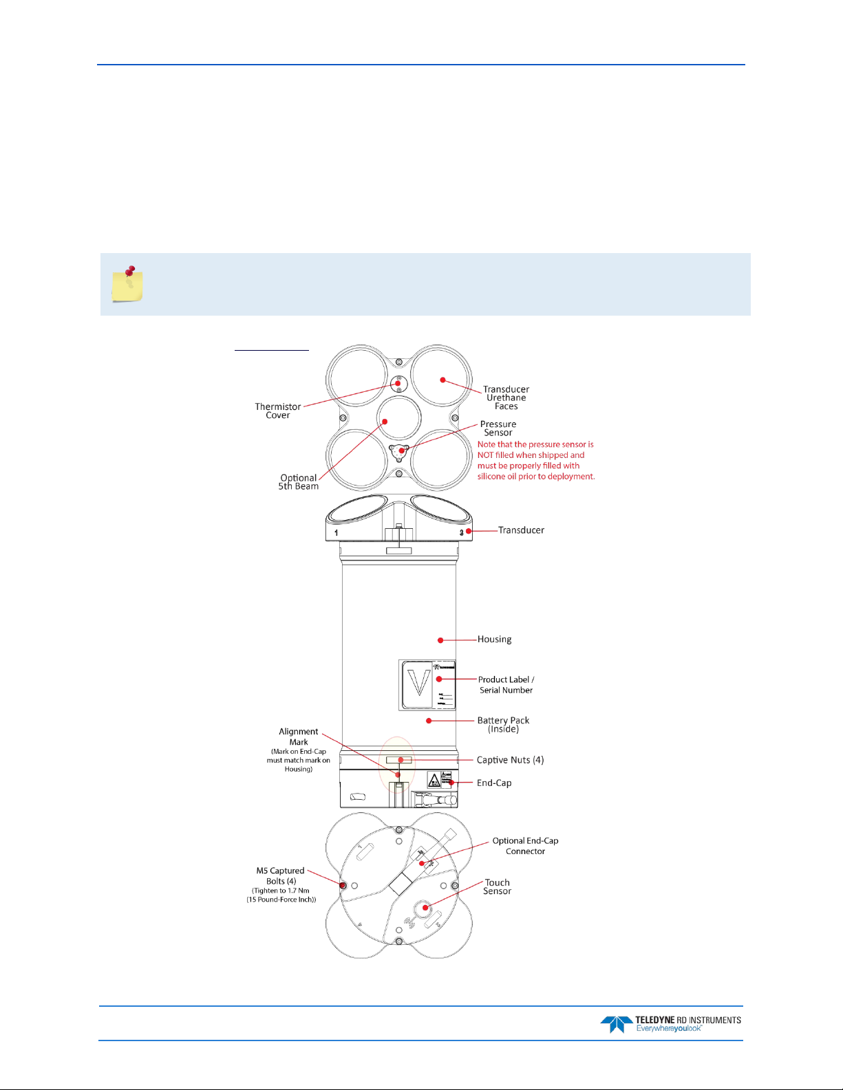
September 2017 Sentinel V SC and RT Operation Manual
Sentinel V Features
The Sentinel V is designed for several-month autonomous current profile deployment from temporary or
permanent mounting in the ocean, near-shore, harbors, and lakes.
The Sentinel V Series ADCP consists of an ADCP, battery pack or individual D cell batteries, microSDHC
memory card, and software. Both battery capacity and memory can be increased with upgrades for longer
deployments. The Sentinel V Series ADCP requires the addition of a Windows® compatible computer to
configure the ADCP and replay collected data.
Figure 1 and Figure 2 only show two of the options and models available with the Sentinel V
Series ADCP (see
After a deployment, systems need to be cleaned thoroughly before the touch sensor will work.
Available Options
).
Figure 1. Sentinel V100 5 Beam Overview with Battery Pack and Optional End-Cap Connector
Page 2
EAR-Controlled Technology Subject to Restrictions Contained on the Cover Page.
Page 19
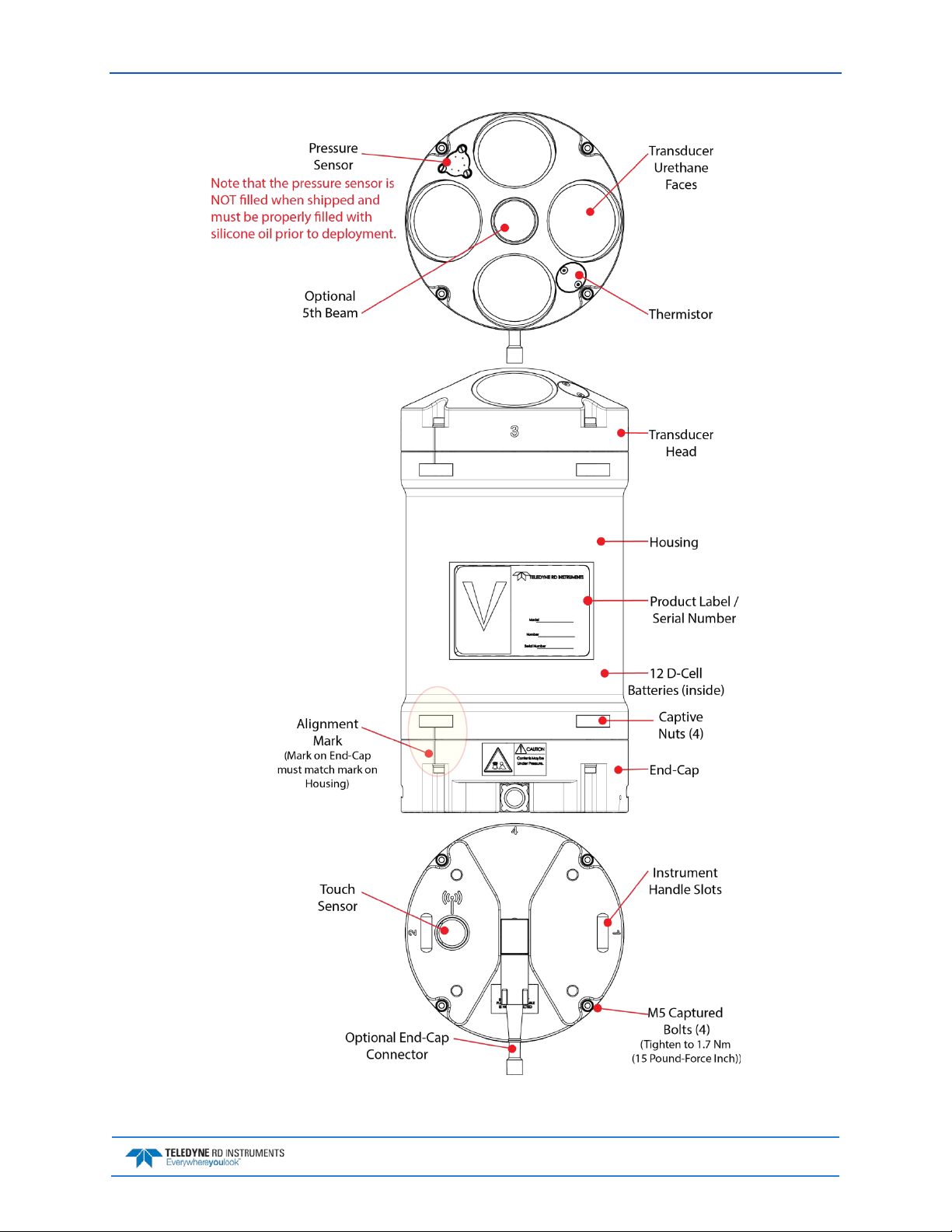
Sentinel V SC and RT Operation Manual September 2017
Figure 2. Sentinel V20 with D Cell Batteries and Optional End-Cap call out beam numbers
EAR-Controlled Technology Subject to Restrictions Contained on the Cover Page.
Page 3
Page 20
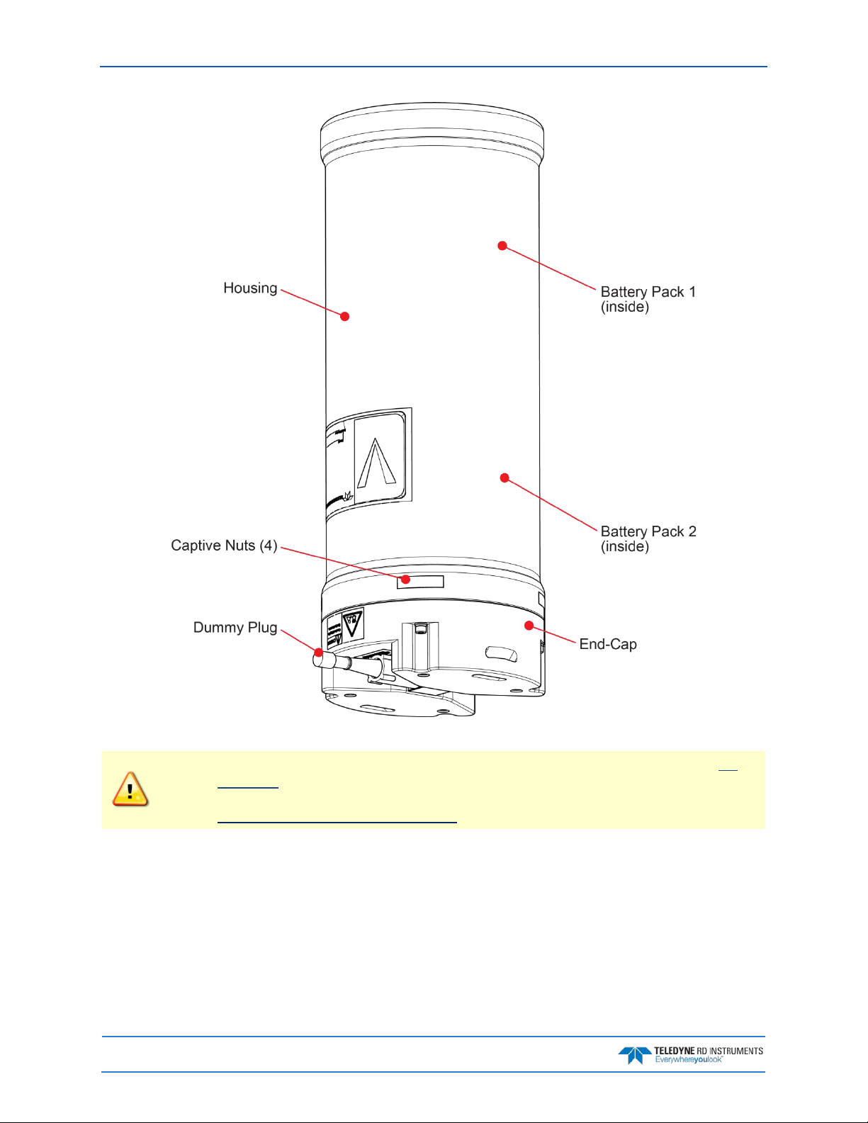
September 2017 Sentinel V SC and RT Operation Manual
Page 4
Figure 3. External Battery Case Overview
The External Battery Case holds two battery packs that are shipped inside the case but not
connected. Connect BOTH batteries and seal the external battery case before deployment. It
is necessary to remove the top battery in order to connect the bottom battery cable. See
Replacing the External Battery Case Packs for details.
EAR-Controlled Technology Subject to Restrictions Contained on the Cover Page.
Page 21
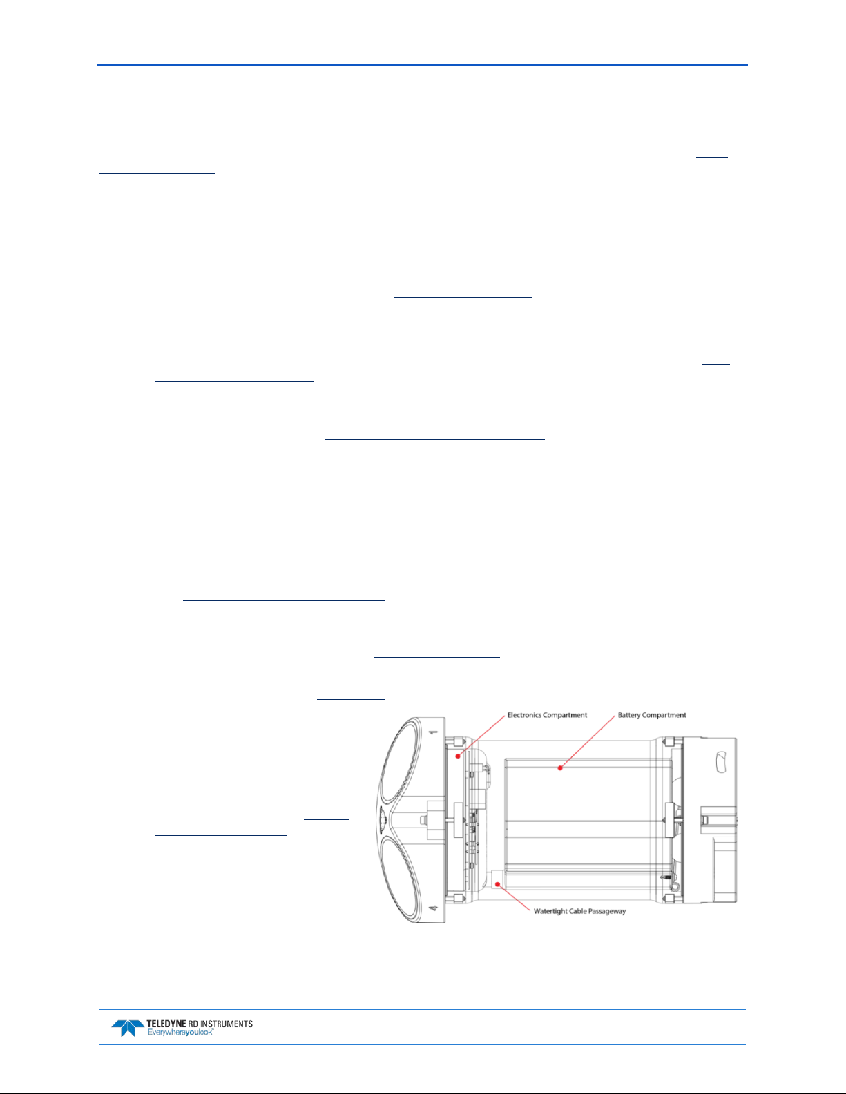
Sentinel V SC and RT Operation Manual September 2017
Available Options
The following section explains the different options available for Sentinel V Series ADCPs. See the Parts
Location Drawings for more information.
• Transducer – The standard nominal ranges are 20m (1000 kHz), 50m (500 kHz) and 100m (300
kHz). See the Outline Installation Drawings
• Vertical Beam – an optional vertical beam is available.
• Waves Feature – Optional feature that provides full water column echo and velocity profiling to
make accurate measurements of wave kinematics as well as the confidence to verify that the processed wave statistics are accurate. See Collecting Waves Data
• End-Cap – The End-Cap consists of an IEEE 802.11b/g/n WLAN wireless communications Touch
Sensor and an optional underwater electrical 8-pin connector.
for dimensions and weights.
for details.
• End-Cap Connector – The optional 8-pin connector can be straight or right-angled. See the
line Installation Drawings for end-cap configurations.
• Real-Time Serial Data Output – If the end-cap has the optional serial port 8-pin connector
installed, you can stream PD0 (PD zero, not the letter o) single ping beam coordinate data
through the serial port. See Using Rea l-Time Serial Data Output
• Internal Batteries – The Sentinel V can use either pre-assembled battery packs or 12 D cell batter-
ies. The battery pack housing uses a pack of 36 D cell al kaline batteries, physically configured as
three stacks of 12 cells for a nominal voltage level of 18 VDC for a fresh battery pack. The D-cell
battery configuration housing uses 12 D cell alkaline batteries for a nominal voltage level of
18 VDC for fresh D cell batteries.
• Lithium Battery Pack – This battery pack is assembled using lithium battery cells that provide 15.6
VDC with a capacity of approximately 1900 Wh. The battery includes a safety circuit that protects the battery and users against short circuits and provides users the ability to test the pack
(see Testing the Lithium Battery Pack
fore the battery fully discharges. This happens when about 97% of the battery’s capacity is depleted.
• External Battery Case – The optional external battery case holds two pre-assembled battery packs
for a nominal voltage level of 18 VDC.
• AC Adapter – The optional AC adapter provides 18 VDC.
• Housing – The standard Sentinel
V Series ADCP dual-chamber
housing allows deployment
depths to 200 meters. The dualchamber design keeps the electronics dry even if the battery
chamber floods. See the
Installation Drawings for dimen-
sions and weights. The housing
type and length will depend on if
it uses battery packs or individual
D cell batteries, or no batteries.
Outline
). The circuit also turns the battery off at its end of life, be-
for details.
Out-
• Memory – The Sentinel V includes
a microSDHC memory card.
• Pressure Sensor – The pressure sensor (standard 30 Bar) measures water pressure (depth).
EAR-Controlled Technology Subject to Restrictions Contained on the Cover Page.
Page 5
Page 22

September 2017 Sentinel V SC and RT Operation Manual
Configuration
S20
Sentinel V SC or RT
Sentinel V Self-Contained (SC) or Real-Time (RT) ADCP. Depending on housing type:
• Sentinel V with no battery housing uses external power.
operate the system.
Accessories Kit
97D-7000-00
97D-7002-00
Shipping Case
Shipping case with foam inserts.
81D-6002-00
Handle
The handle makes it easier to carry the Sentinel V ADCP. Attach it to the slots on the
75DK6001-00
Tools and Spare
See Tools and Spare Parts for a list of parts included in this kit.
95D-6037-00
Sentinel V SC and
Use this sheet to determine where to start on setting up the Sentinel V SC and RT
Documentation Kit
Sentinel V
and Software CD
This CD has PDF versions of all of the Sentinel V documentation and software including
Deployment Guides!
95D-6016-00
Compass
Printed sheet with instructions on how to calibrate the compass. A PDF version is
95Z-8005-00
Velocity Activation
Activation code that unlocks the Velocity software. Waves processing requires a waves
95D-6015-00
Deployment Guide
A printed copy of the SC and RT deployment guides.
System Inventory
Included with the Sentinel V system:
Kit Part Number Name Description
S50
S100
See the packing slip for more
information on system configuration
or
95D-8001-00
ADCP with
transducer cover
Parts kit
RT Roadmap
Documentation
Calibration Guide
Code
• Sentinel V battery packs are shipped inside the system but not connected.
• Sentinel V with D cells are shipped without batteries inside the system.
SC systems use wireless communications for setup and deployment. This means the system only requires battery power to operate the system.
RT systems use serial or Ethernet communications for setup and deployment. This
means an end-cap with connector, an underwater cable, and DC power are required to
ADCP’s end-cap.
system.
the Sentinel V SC and RT Operation Manual. Please read the manual and the SC and RT
included on the documentation CD.
enabled activation code.
95D-6033-00
Software Overview
Sentinel V Self-Contained Software:
Waves
Currents ReadyV ReadyV ReadyV ReadyV ReadyV Velocity Velocity Velocity
Testing Planning Compass Cal
ReadyV WavesMon ReadyV WavesMon WavesMon WavesMon WavesMon WavesMon
ReadyV WavesView ReadyV Velocity
User Supplied
Command
& Control
Read the Self-Contained Deployment Guide for instructions on installing the software.
Data
Acquisition
Display Data Convert Post Process
Page 6
EAR-Controlled Technology Subject to Restrictions Contained on the Cover Page.
Page 23

Sentinel V SC and RT Operation Manual September 2017
Computer Considerations
TRDI designed the Sentinel V Series Self-Contained ADCP to use a Windows® compatible computer. The
built-in ReadyV user interface configures the ADCP and data is displayed through TRDI’s Velocity program.
Minimum Computer Hardware Requirements:
• Desktop, Laptop, or Netbook computer (see Table 1 for operating system)
• Screen resolution above 1024x768 (see note)
• Internet Brower (see Table 1 for supported browsers)
• Mouse or other pointing device
• Wireless 802.11 b/g/n WLAN Interface
Many laptops and netbooks today have built-in WLAN. If not, then a WLAN adapter is required.
Most wireless enabled laptops will be automatically enabled. Consult the instruction manual for
your specific device if you are not sure how to do so.
Laptops running on Windows XP® may have display issues when using a screen resolution of
1024x768. A workaround is to change the zoom level in the browser so that the entire ReadyV
screen is visible.
ReadyV does not support Windows 8 Internet Explorer® 10 Metro browser.
Users may need to turn off their browser pop-up blockers (either built-in or third party) in order
to access ReadyV.
When using Firefox, a javascript: void(0) message or a long "Javascript:..." string shows up in the
left lower corner in when you mouse over some buttons. These messages can be ignored.
Table 1. Supported Operating Systems and Browsers
Operating System
Windows® 7, 8.1, 10 (32/64 bit)
Macintosh OS 10.5.7+ (Intel based)
Linux (any 32/64 bit distribution)
Internet Explorer
10+
Firefox (Latest) Safari (Latest) Chrome (Latest) Opera (Latest)
Not Supported
EAR-Controlled Technology Subject to Restrictions Contained on the Cover Page.
Page 7
Page 24

September 2017 Sentinel V SC and RT Operation Manual
Power Considerations
Use the following section to determine the power requirements for the Sentinel V Self-Contained ADCPs.
• The Sentinel V system uses +18 VDC to operate.
• Depending on the type of housing the system is configured with, the ADCP may use a battery
pack, lithium battery pack (optional), individual D cell batteries, or external power.
• If the Sentinel V is configured with the optional end-cap connector, then external power can be
used. The voltage must be +12 to 20 VDC. The optional AC power adapter
Transmitted Power
Sentinel V battery pack is shipped inside the system but not connected. Connect the
battery and seal the Sentinel V before deployment.
Sentinel V with D cells are shipped without batteries inside the system. Install the batteries
and seal the Sentinel V before deployment.
The External Battery Case holds two battery packs that are shipped inside the case but not
connected. Connect BOTH batteries and seal the external battery case before deployment. It
is necessary to remove the top battery in order to connect the bottom battery cable. See
Replacing the External Battery Case Packs for details.
provides +18 VDC.
For the Sentinel V, a fresh battery provides +1 8 VDC . Batteries spend most of their life at a nominal voltage of +14 VDC. Using 18 VDC will increase the range by 5 to 10% depending on conditions.
The optional lithium battery provides 15.6 VDC with a capacity of approximately 1900 Wh. The battery
includes a safety circuit that protects the battery and users against short circuits and provides users the
ability to test the pack. The circuit also turns the battery off at its end of life, before the battery fully discharges. This happens when about 97% of the battery’s capacity is depleted.
Power on Cycle
The power supply or battery pack must be able to handle the inrush current as well. Inrush current is the
current required to fully charge up the capacitors when power is applied to the Sentinel V Series ADCP.
The capacitors provide a store of energy for use during transmit. The inrush current is as high as 0.8
Amps RMS at 9.2 VDC. The ADCP will draw this amperage until its capacitors are fully charged. If the
power supply or battery pack limits the current or the power drop on the cable is significant, then the
power on cycle will take longer. It can take up to three minutes. The power must not shut down during the
inrush current draw, as this may not allow the Sentinel V Series ADCP electronics to start.
Before using the optional Lithium battery pack, always run the battery self-test. See Testing
the Lithium Battery Pack for instructions.
Instruments with high inrush currents occasionally trigger the optional Lithium battery pack
short circuit detection, which turns the battery off. If this happens, do the following:
• Disconnect the battery and touch the ADCP’s touch sensor for about 45 seconds to
one minute. Connect the battery and then the ADCP should power on normally.
• If the ADCP still does not power on, connect the AC adapter and wait for a minute
and then connect the battery pack. Once the ADCP is connected and ReadyV started,
unplug the AC adapter. The ADCP will work normally after that.
Page 8
EAR-Controlled Technology Subject to Restrictions Contained on the Cover Page.
Page 25
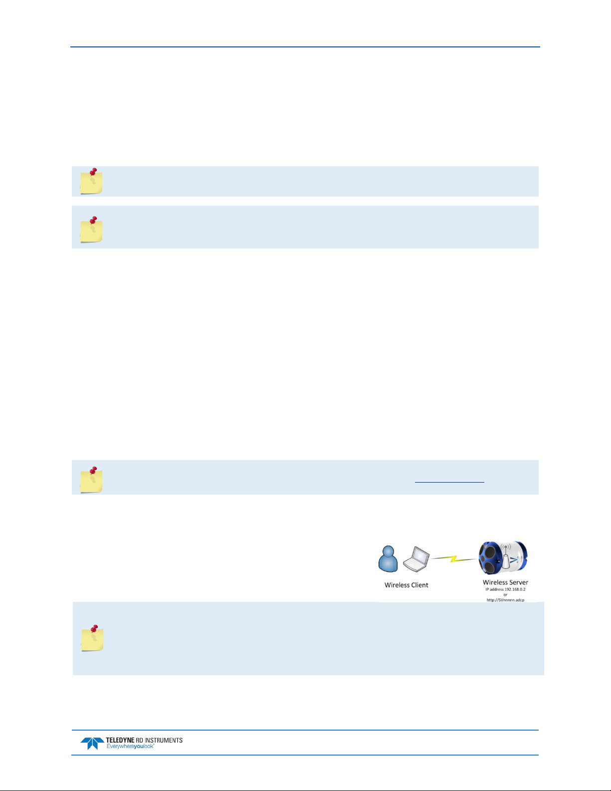
Sentinel V SC and RT Operation Manual September 2017
Touch Sensor Response / System Beeps
When the system is configured for SC mode, after power is applied (long beep), there is a 10 to 15 second
delay before the network is available (short beep). During this time span, the touch sensor does not respond or beep if touched. Wait until the second beep before touching the sensor. The WLAN is
available after the second beep for two minutes. Each touch of the sensor enables the WLAN for two
minutes.
During the first power-up of the Sentinel V ADCP, there may be additional beeps. This is due
to the touch sensor auto-calibration routine, which should not last longer than five minutes.
When the system is configured for Sentinel V Real-Time and power is applied, there is a long
beep. The touch sensor is disabled in Real-Time mode; the touch sensor does not respond or
beep if touched.
The touch sensor may stay “triggered” for up to 60 seconds when touched. During this time, the sensor
will not respond with a beep when touched again. This is normal and does not affect connecting to the
WLAN.
The touch sensor can be saturated to a point where it won’t register to touch. This occurs, for example,
when the ADCP is submerged in water or covered with biofouling. In extreme cases, the WLAN will not
connect. If this occurs:
• Take the system out of the water.
• Rinse the sensor and end-cap with fresh water and then dry the instrument.
• Remove biofouling from the touch sensor and end-cap, and then the housing if problems persist.
• Remove the ADCP from any mounting fixture, especially if it is conductive or metallic.
Connecting to the Sentinel V ADCP
This applies to systems configured for Self-Contained mode. See Switching Modes.
The Sentinel V Self-Contained ADCP includes an 802.11b/g/n WLAN interface and a built-in user interface called ReadyV. The Sentinel V Series ADCP acts as the server, along with the connected computer
(laptop, tablet, or desktop computer) known as the client.
Using the ADCP’s DHCP server IP address 192.168.0.2 is recommended. Optionally, on a Windows® based browser use the WLAN
address http://SVnnnnn.adcp (where nnnnn is the five or six-character Sentinel V serial number shown on the product label).
If the computer does not include a built-in 802.11b/g/n WLAN interface, use a USB adapter.
Only one ADCP at a time may be connected. To switch to another ADCP, first disconnect, and
then reconnect to the next ADCP.
Using http://SVnnnnn.adcp (where nnnnn is the five or six-character Sentinel V serial number
shown on the product label) will not work on the Macintosh OS.
EAR-Controlled Technology Subject to Restrictions Contained on the Cover Page.
Page 9
Page 26
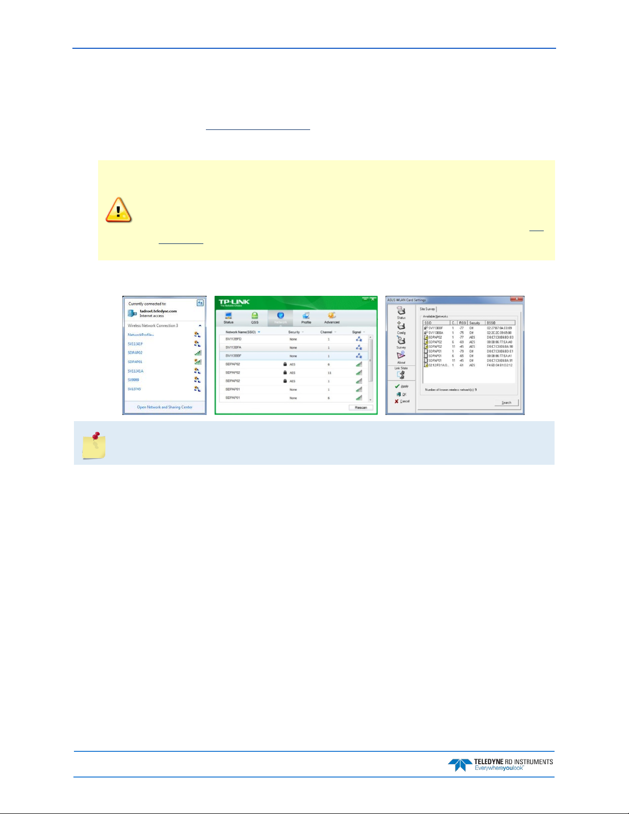
September 2017 Sentinel V SC and RT Operation Manual
Using the Wireless Connection
To connect to the ADCP:
1. Prepare the ADCP by connecting the battery.
After power is applied (long beep), there is a 10 to 15
second delay before the net wo rk is available (short beep). The WLAN is available after power up
for two minutes.
Sentinel V battery pack is shipped inside the system but not connected. Connect the
battery and seal the Sentinel V before deployment.
Sentinel V with D cells are shipped without batteries inside the system. Install the batteries
and seal the Sentinel V before deployment.
The External Battery Case holds two battery packs that are shipped inside the case but not
connected. Connect BOTH batteries and seal the external battery case before deployment.
It is necessary to remove the top battery in order to connect the bottom battery cable.
2. Start the wireless network device on the laptop if it is not automatically enabled. This may be a
built-in wireless connection on a laptop or a USB wireless adapter.
The screen shots in this manual were made with Windows® 7. Depending on the operating
system and wireless adapter type, your wireless screen may look different. These differences
do not affect the performance of ReadyV.
Page 10
EAR-Controlled Technology Subject to Restrictions Contained on the Cover Page.
Page 27
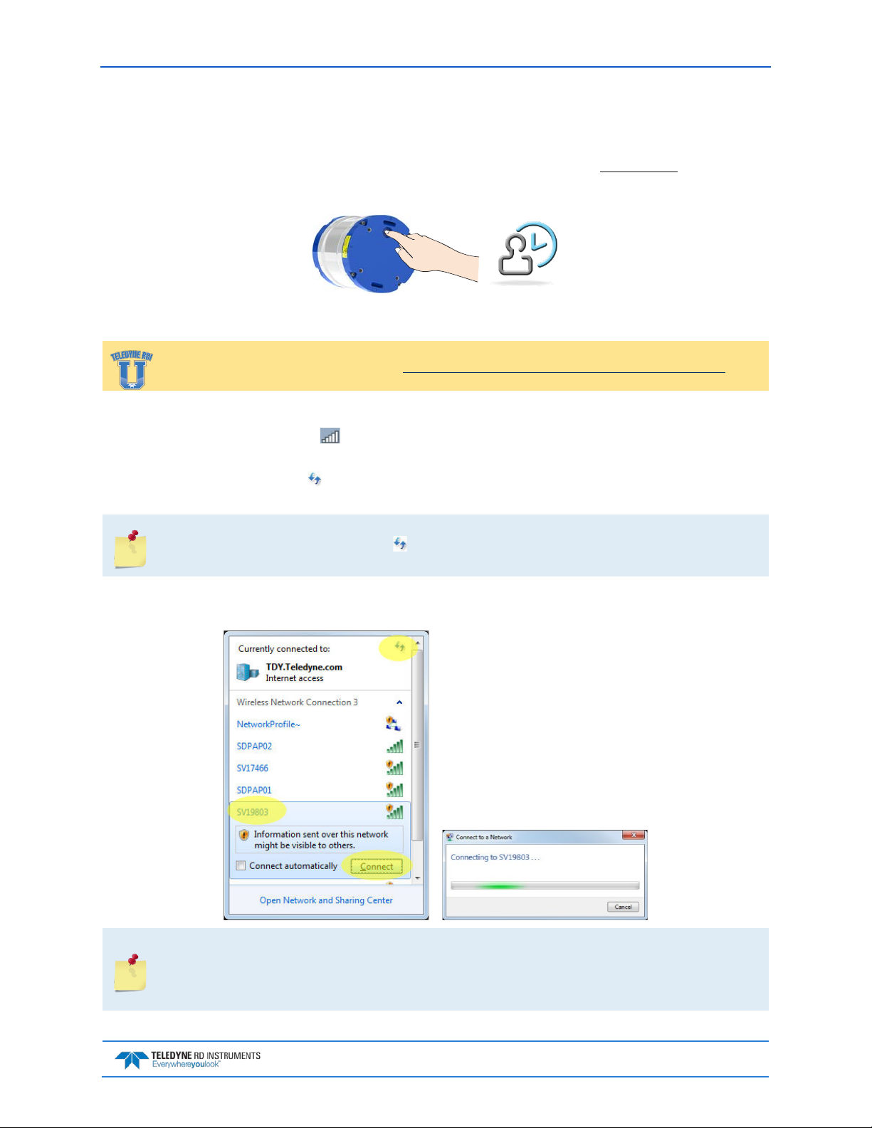
Sentinel V SC and RT Operation Manual September 2017
Touch Sensor
To use the touch sensor:
Place a finger over the Touch Sensor. This starts the ADCP’s WLAN for five minutes. After power
1.
is applied (long beep), there is a 10 to 15 second delay before the network is available (short beep).
Wait for the short beep.
Connect
Training videos are available on http://www.rdinstruments.com/rdiu/mm_training.aspx.
To connect to the ADCP’s WLAN:
1. Click on the wireless icon ( ) in the Windows® system tray or if using a wireless USB adapter,
start the adapter’s interface.
2. Click the Refresh icon ( ) to search for connections. Sentinel V ADCPs will display as SVnnnnn
(where nnnnn is the five or six-character serial number shown on the product label).
As needed, touch the Touch Sensor, listen for the second beep (see Touch Sensor Response /
System Beeps), and then click until the ADCP appears on the list. It may take several
attempts of clicking Refresh before the ADCP appears on the list.
3. Select the ADCP on the list by clicking it and then click the Connect button. The Connecting to a
Network message appears.
Sentinel V ADCPs will display as SVnnnnn (where nnnnn is the five or six-character serial
number shown on the product label).
Users who connect to their local network using a wireless connection may lose that
connection when connected to the ADCP.
EAR-Controlled Technology Subject to Restrictions Contained on the Cover Page.
Page 11
Page 28

September 2017 Sentinel V SC and RT Operation Manual
Start ReadyV
To start ReadyV:
®
1. Open a browser on the laptop (Internet Explorer
2. Enter the ADCP’s IP address 192.168.0.2 into the address bar. Optionally, on a Windows®
based browser use the WLAN address http://SVnnnnn.adcp (where nnnnn is the five or six-character Sentinel V serial number shown on the product label).
The DHCP server IP address 192.168.0.2 works for all ADCP serial numbers and all browsers
and operating systems.
The address is not case sensitive - enter SVnnnnn or svnnnnn.
The http:// does not need to be typed on most browsers.
Using http://SVnnnnn.adcp will not work on the Macintosh OS.
Add the Sentinel V to the browser’s Internet Favorites or Favorites bar for future
connections.
3. White panels will appear after the ADCP’s address is e ntered : It can take up to 30 seconds before
the ReadyV Home
panel fully opens.
, FireFox®, Google Chrome®, or other browser).
As needed, touch the Touch Sensor, listen for the beep, and then refresh the browser page
until ReadyV starts.
Complete step 3 within five minutes of completing step 2.
Page 12
EAR-Controlled Technology Subject to Restrictions Contained on the Cover Page.
Page 29
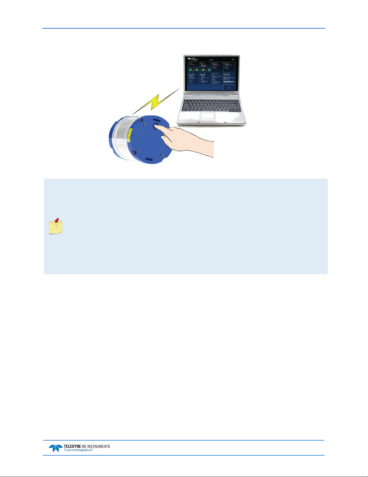
Sentinel V SC and RT Operation Manual September 2017
Figure 4. Using the ReadyV Wireless Connection
The Touch Sensor is NOT a button! Just place a finger into the cavity to activate the sensor.
After power is applied (long beep), there is a 10 to 15 second delay before the network is
available (short beep). Wait for the short beep before trying to connect.
The ADCP’s WLAN is available after power up for five minutes. Placing a finger over the Touch
Sensor starts the WLAN for another five minutes.
Each time the Touch Sensor is touched, a short beep should be heard.
Only one ADCP at a time may be connected. To switch to another ADCP, first disconnect, and
then connect to the next ADCP.
Once ReadyV starts, if no keys are pressed for five minutes, the ADCP will disconnect. After
waiting five more minutes, the ADCP will power down. Use the Touch Sensor to restart.
After a deployment, systems need to be cleaned thoroughly before the touch sensor will work.
EAR-Controlled Technology Subject to Restrictions Contained on the Cover Page.
Page 13
Page 30

September 2017 Sentinel V SC and RT Operation Manual
Connecting to another ADCP
To connect to another ADCP:
1. Click on the wireless access-point icon ( ) in the Windows® system tray and select the ADCP on
the list that is connected.
2. Click the Disconnect button.
3. Now connect
to the next ADCP.
Only one ADCP at a time may be connected. To switch to another ADCP, first disconnect, and
then connect to the next ADCP.
Page 14
EAR-Controlled Technology Subject to Restrictions Contained on the Cover Page.
Page 31

Sentinel V SC and RT Operation Manual September 2017
Restoring a ReadyV Lost Connection
Once ReadyV starts, if no keys are pressed for five minutes, the ADCP will disconnect. After waiting five
more minutes, the ADCP will power down. Once the ADCP powers down, the wireless connection is lost.
To reconnect:
1. Close the internet browser page or the browser tab which was running ReadyV.
2. Use the Touch sensor to reconnect (see Connecting to the ADCP
If the ADCP appears on the list but the laptop fails to connect to it, Windows® 7 may have
kept the name on the list because it connected to that network in the past. In other words,
this does not mean that the network is actually available. When in doubt, select the ADCP on
the list and use the Disconnect button and then restart the connection.
).
EAR-Controlled Technology Subject to Restrictions Contained on the Cover Page.
Page 15
Page 32
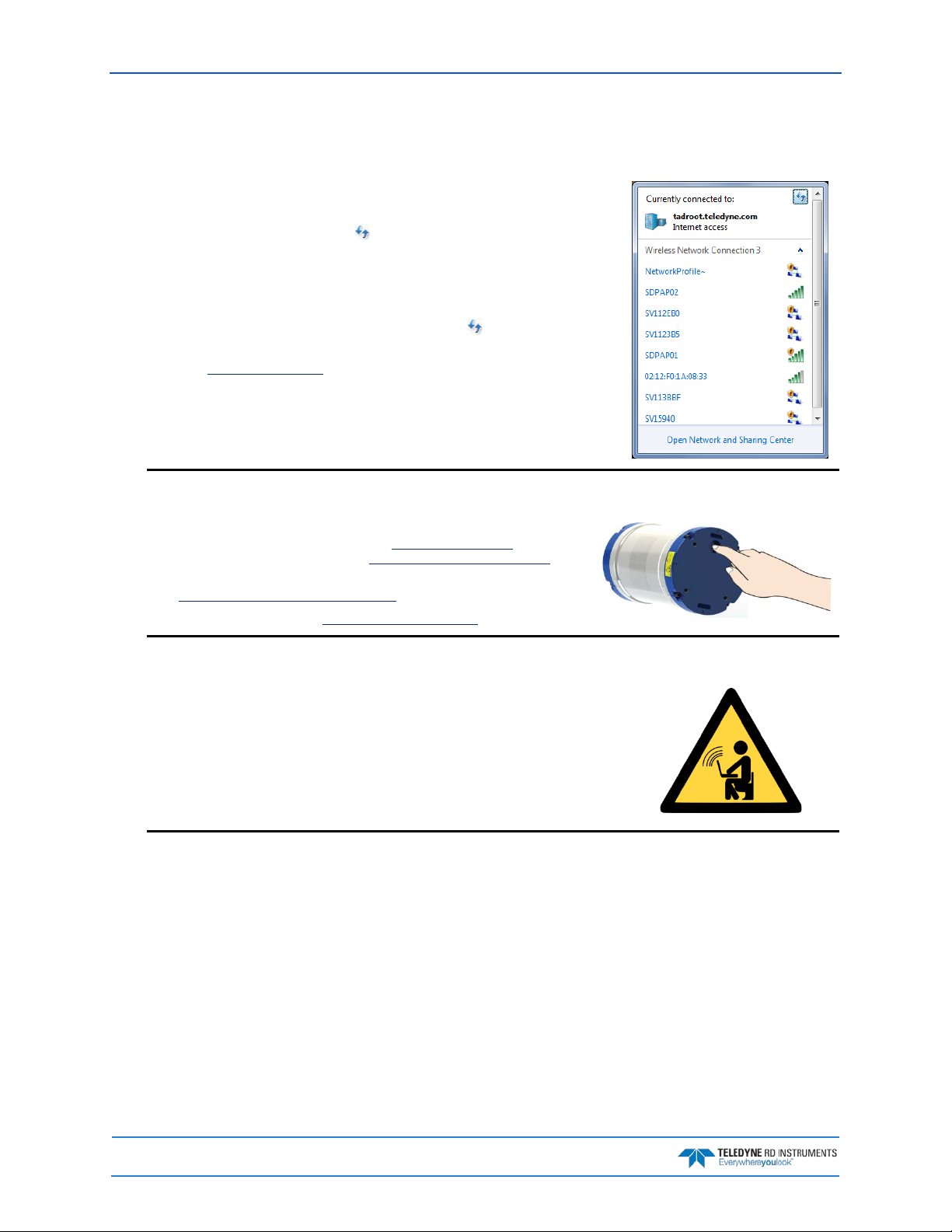
September 2017 Sentinel V SC and RT Operation Manual
The ADCP may have timed out. Place a finger over the Touch Sensor again. There
Check that the battery is installed.
Start the wireless network device on the laptop if it is not automatically enabled.
Wireless Connection Common Issues
The ADCP does not appear on the list of devices:
is a short beep indicating that the WLAN is enabled on the ADCP. The ADCP’s
WLAN will remain on for five minutes after the short beep. It may take several at-
tempts of clicking the Refresh icon ( ) before the ADCP appears on the list.
Another computer may already be connected to the ADCP. Only one computer may
be connected to an ADCP at a time.
The ADCP does not have power – connect the battery. After power is applied (long
beep), there is a 10 to 15 second delay before the network is available (short beep).
Wait for the short beep before clicking the Refresh icon ( ).
If the touch sensor is blocked with biofouling, thoroughly clean the sensor cavity
first (see Removing Biofouling
There are no beeps when the touch sensor is touched:
).
If you are using a lithium battery pack, see Power Considerations. Test the
lithium battery pack safety circuit. See Testing the Lithium Battery Pack for
instructions.
See Touch Sensor Response / System Beeps.
If there are still problems, see Chapter 6 - Troubleshooting.
There are no ADCPs on the list of devices:
This may be a built-in wireless connection on a laptop or a USB wireless adapter.
Look for a hardware switch or special function key on the laptop that can turn the
wireless radio on or off. Consult the instruction manual for your specific laptop if
you are not sure how to do so.
If the computer uses an external wireless adapter, make sure the adapter is working
correctly and is attached and installed properly.
Try using a different USB wireless adapter.
Page 16
EAR-Controlled Technology Subject to Restrictions Contained on the Cover Page.
Page 33

Sentinel V SC and RT Operation Manual September 2017
Windows 7 may indicate it is connected and the signal strength is excellent even if the
If the ADCP appears on the list but the laptop fails to connect to it, Windows® 7
Once the instrument is deployed and no keys are pressed for five minutes, a warning
The ADCP is connected, but ReadyV does not start:
wireless connection is lost due to the ADCP going to sleep.
Click on the wireless access-point icon ( ) in the Windows® system tray and click
on the ADCP connected to. Click the Disconnect button and then click the Connect
button to reconnect to the network.
Close and then restart the browser.
The ADCP is on the list, but WLAN connection fails:
may have kept the name on the list because it connected to that network in the
past. In other words, this does not mean that the network is actually available.
Touch the Wireless Touch Sensor to start the network. Listen for the two beeps:
the first one confirms the sensor detected your finger and the second beep confirms the wireless network is ON. Placing a finger over the Touch Sensor starts the
network for five minutes. Try to connect again.
If the touch sensor is blocked with biofouling, thoroughly clean the sensor cavity
first (see Removing Biofouling
If there are no beeps, make sure that the ADCP is properly powered.
).
ReadyV Timed-out; the ADCP wireless is ON but refreshing the web page does not work:
message is displayed, and after another five minutes of no keys being pressed the
wireless connection is turned off on the ADCP. Clicking Cancel at the first ReadyV
info message will leave ReadyV running.
To run ReadyV again and connect to the ADCP, first close the internet browser page
or the browser tab which was running ReadyV and then restart the connection.
EAR-Controlled Technology Subject to Restrictions Contained on the Cover Page.
Page 17
Page 34

September 2017 Sentinel V SC and RT Operation Manual
Make sure the IP address 192.168.0.2 is typed in correctly.
Windows 7® may display a Set Network Location page (Home network, Work
This is normal. It can take up to 30 seconds for the Home panel to display. Wait
When the browser is opened, there is a page not found error:
If you are using a Windows ® browser, try using the ADCP’s WLAN address
http://SVnnnnn.adcp into the address bar (where nnnnn is the five or six-character
Sentinel V serial number). The address is not case sensitive.
Some browsers may open a search page if the http:// portion in the address bar is not
entered.
Check the network connection.
If the computer has both a network cable and wireless, try unplugging the network ca-
ble.
What type of network should be selected?
network, or Public network page) after connecting to the ADCP.
This page is not needed. Click Cancel to close the page.
There are white panels when the ADCP’s address is entered:
for the page to open.
Click on the Refresh Page button on the browser.
Close the browser and reopen.
Try using a different browser. See Computer Considerations
The ADCP is deployed. See Starting or Stopping Deployments.
.
Page 18
EAR-Controlled Technology Subject to Restrictions Contained on the Cover Page.
Page 35

Sentinel V SC and RT Operation Manual September 2017
Once ReadyV starts, if no keys are pressed for five minutes, the ADCP will discon-
Use the Touch sensor and refresh the browser page. If that does not help, the wire-
Make sure there are no other devices interfering with the ADCP, such as micro-
The connection was lost:
nect. After waiting five more minutes, the ADCP will power down. First close the
internet browser page or the browser tab which was running ReadyV and then use
the Touch sensor to restart.
less connection was lost. Click on the wireless access-point icon ( ) in the Windows® system tray and check the connection.
If the firmware was just updated, the browser must be closed and the wireless network must be restarted.
wave ovens, cordless phones, or other wireless devices.
Make sure the ADCP is within the wireless range of the computer (typically within
100 feet). Try moving the ADCP closer to the computer. If there is a wall between
the ADCP and the computer, try placing the ADCP and computer in the same
room. Click the wireless access-point icon ( ) on the status bar and check the signal strength by right-clicking on the connection and selecting
Status.
EAR-Controlled Technology Subject to Restrictions Contained on the Cover Page.
Page 19
Page 36

September 2017 Sentinel V SC and RT Operation Manual
NOTES
Page 20
EAR-Controlled Technology Subject to Restrictions Contained on the Cover Page.
Page 37

Sentinel V SC and RT Operation Manual September 2017
Chapter 1a
REAL-TIME SENTINEL V OVERVIEW
In this chapter, you will learn:
• Sentinel V Real-Time ADCP features
• Health & Environment Monitoring Sensors
• Comparing Self-Contained & Real-Time
• What type of computer do I need?
• What are the ADCP power requirements?
• Connecting to the Sentinel V Real-Time
• Switching RT and SC Modes
• Using the Sentinel-V Real-Time Utilities Page
• Using the Trigger
EAR-Controlled Technology Subject to Restrictions Contained on the Cover Page.
Page 21
Page 38

September 2017 Sentinel V SC and RT Operation Manual
Sentinel V Real-Time Features
Sentinel V Real-Time ADCP is designed for real-time applications such as vessel-mount, waves, and turbulence. It is a direct-read capable ADCP based on the Sentinel V hardware. It can be sold as a new unit,
or as a field-upgradeable “kit”. Firmware upgrades from Real-Time (and back to) Self-Contained allows
dual-application use.
The Sentinel V Real-Time ADCP consists of an ADCP, housing with serial or Ethernet connector, microSDHC memory card, and software. The Sentinel V Real-Time Series ADCP requires the addition of a
Windows® compatible computer to configure the ADCP and replay collected data.
The figure below shows the no battery Real-Time (RT) housing (see Available Real-Time
Options), but any V Series housing with a serial connector can be used. The “no connector”
option is not compatible with a Sentinel V Real-Time.
Page 22
Figure 5. Real-Time (RT) Housing Overview
EAR-Controlled Technology Subject to Restrictions Contained on the Cover Page.
Page 39

Sentinel V SC and RT Operation Manual September 2017
Available Real-Time Options
The following section explains the different options available for RT ADCPs. See the Parts Location Draw-
ings for more information.
• Transducer – The standard nominal ranges are 20m (1000 kHz), 50m (500 kHz) and 100m (300
kHz). See the Outline Installation Drawings
• Vertical Beam – an optional vertical beam is available.
• Waves Feature – Optional feature that provides full water column echo and velocity profiling to
make accurate measurements of wave kinematics as well as the confidence to verify that the processed wave statistics are accurate. Use Plan to set up the Sentinel V Real Time ADCP to collect
Waves data. See Installing Feature Upgrades
• End-Cap – The End-Cap consists of an IEEE 802.11b/g/n WLAN wireless communications Touch
Sensor and underwater electrical 8-pin serial RS-232 or RS-422 connector. Please note that the
touch sensor is disabled while in Real-Time mode.
for dimensions and weights.
for more information.
• End-Cap Connector – The 8-pin connector can be straight or right-angled. See the
Outline Instal-
lation Drawings for end-cap configurations.
• Deck Box – The Deck Box converts AC power input into 16 VDC output for the Sentinel V RT in-
put power. It can convert the computer serial interface from RS232 to RS422.
• Internal Batteries – Depending on the type of housing the system is configured with, the Sentinel
V Real Time system may use a battery pack, lithium battery pack (optional), individual D cell
batteries, external power only, or both external power and batteries.
• Lithium Battery Pack – This battery pack is assembled using lithium battery cells that provide 15.6
VDC with a capacity of approximately 1900 Wh. The battery includes a safety circuit that protects the battery and users against short circuits and provides users the ability to test the pack
(see Testing the Lithium Battery Pack
). The circuit also turns the battery off at its end of life, before the battery fully discharges. This happens when about 97% of the battery’s capacity is depleted.
• External Battery Case – The optional external battery case holds two pre-assembled battery packs
for a nominal voltage level of 18 VDC.
• AC Adapter – The AC adapter provides 18 VDC.
• Underwater Cable – The system includes a 5-meter underwater serial or Ethernet cable. The max-
imum cable length is 100 meters.
• Housing – The Sentinel V Series
ADCP dual-chamber housing allows deployment depths to 200
meters. The dual-cham be r d esign
keeps the electronics dry even if
the battery chamber floods. See
the Outline Installation Drawings
for dimensions and weights. The
housing type and length will depend on if it uses battery packs or
individual D cell batteries. The RT
(no battery) housing uses a single
chamber.
• Memory – The Sentinel V includes a microSDHC memory card.
• Pressure Sensor – The pressure sensor (standard 30 Bar) measures water pressure (depth).
EAR-Controlled Technology Subject to Restrictions Contained on the Cover Page.
Page 23
Page 40

September 2017 Sentinel V SC and RT Operation Manual
Health & Environment Monitoring Sensors
The Health and Environment Monitoring (HEM) Sensors monitor the health of the Sentinel V Real-Time
system.
• Operating Time – The Sentinel V Real-Time system records the total time of operation in
minutes where “operation” is defined as the time that the system ping loop is active (CS command has been sent). The record of the total awake time has a maximum value of 33,554,432
minutes, which corresponds to over 500,000 hours of operation. The value of the counter can
be read as part of the PS5 command. Although the time is stored in minutes, the operating
time is reported in hours with one decimal place.
• Pressure Cycles – Sentinel V Real-Time systems with pressure sensors installed record the
number of pressure cycles (dives, casts, etc.) to which a unit is exposed during operation. A
pressure cycle is defined as “pressure is greater than 40% of maximum, followed by a pressure that is less than 20% of maximum”. The pressure cycle counter has a maximum value of
16,384. Use the PS5 command to read the number of pressure cycles.
• Maximum Pressure – Sentinel V Real-Time systems with pressure sensors installed monitor
the pressure during operation and records the maximum pressure seen during the lifetime of
the instrument. This maximum pressure is stored in non-volatile memory. The PS5 output
will read N/A if no pressure was measured or recorded. Use the PS5 command to read the
maximum pressure seen.
• Over Pressure – Sentinel V Real-Time systems with pressure sensors installed monitor water
pressure during operation and record the number of events beyond the system’s maximum
rated pressure value. The system pressure rating is defined as the maximum pressure rating
of the installed pressure sensor. The system maintains a flag in non-volatile memory to indicate whenever the pressure exceeds 100% of the maximum rated value, this flag is set to a ‘1’
value, and whenever pressure is less than 80% of the maximum rated value, this flag is
cleared to a ‘0’ and the over pressure cycle counter is incremented. Use the PS5 command to
read the number of over pressure events seen.
The Sentinel V Real-Time system pressure rating is defined as the maximum pressure rating
of the installed pressure sensor.
If an Over Pressure event occurs or the Maximum Pressure seen has exceeded the Sentinel V
Real-Time’s pressure sensor depth rating, TRDI advises returning the system to us for an
inspection before re-deploying.
Example PS5 output:
PS5
Operating time: 4327.5 hours
Maximum pressure seen: 652.378 dBar
Over-pressure events: 1
Pressure cycles: 25
Page 24
EAR-Controlled Technology Subject to Restrictions Contained on the Cover Page.
Page 41

Sentinel V SC and RT Operation Manual September 2017
Comparing Self-Contained & Real-Time
The V Series ADCP can be converted to a Sentinel V Real-Time and vice versa by changing the firmware
(see Switching RT and SC Modes
).
Sentinel V Self-Contained Sentinel V Real-Time
Real-Time currents, Continuous Waves,
Intended Applications Self-Contained currents, Waves (Burst)
Turbulence, Vessel Mount/Moving
Platform
Ping Rate Up to 4Hz Up to 16Hz (Frequency dependent)
Water Modes Water profile (WM2) Water Profile (WM2),
Bottom-Track No Yes
Trigger No Yes
Sleep Yes No
Data recording Data Recording No
Plan Software ReadyV Sentinel V RT Utilities
Profiles Dual Single
Config error checking Profile and schedule in-depth validation Limited
Saved configurations Multiple, named 1 user, 1 default
Maintenance log Yes, user accessible No
Feature control Yes, using Ready V Yes, using Sentinel V RT Utilities
Burst scheduling Yes No
Vertical beam Profile (Software only; Velocity/WavesMon)
HEM features None Selected
Comms WLAN control, Serial output RS232 Serial, RS232 or RS422, Ethernet
Firmware upgrade Wireless, enabled via touch sensor Wireless, enabled via serial or Ethernet
SC-RT conversion Firmware change
EAR-Controlled Technology Subject to Restrictions Contained on the Cover Page.
Page 25
Page 42

September 2017 Sentinel V SC and RT Operation Manual
Configuration
S20
Sentinel V SC or RT
Sentinel V Self-Contained (SC) or Real-Time (RT) ADCP. Depending on housing type:
• Sentinel V with no battery housing uses external power.
operate the system.
Accessories Kit
97D-7000-00
97D-7002-00
Shipping Case
Shipping case with foam inserts.
81D-6002-00
Handle
The handle makes it easier to carry the Sentinel V ADCP. Attach it to the slots on the
75DK6001-00
Tools and Spare
See Tools and Spare Parts for a list of parts included in this kit.
95D-6037-00
Sentinel V SC and
Use this sheet to determine where to start on setting up the Sentinel V SC and RT
Documentation Kit
Sentinel V
and Software CD
This CD has PDF versions of all of the Sentinel V documentation and software including
Deployment Guides!
95D-6016-00
Compass
Printed sheet with instructions on how to calibrate the compass. A PDF version is
95Z-8005-00
Velocity Activation
Activation code that unlocks the Velocity software. Waves processing requires a waves
95D-6015-00
Deployment Guide
A printed copy of the SC and RT deployment guides.
Real-Time System Inventory
Included with the Sentinel V system:
Kit Part Number Name Description
S50
S100
See the packing slip for more
information on system configuration
or
95D-8001-00
ADCP with
transducer cover
Parts kit
RT Roadmap
Documentation
Calibration Guide
Code
• Sentinel V battery packs are shipped inside the system but not connected.
• Sentinel V with D cells are shipped without batteries inside the system.
SC systems use wireless communications for setup and deployment. This means the system only requires battery power to operate the system.
RT systems use serial or Ethernet communications for setup and deployment. This
means an end-cap with connector, an underwater cable, and DC power are required to
ADCP’s end-cap.
system.
the Sentinel V SC and RT Operation Manual. Please read the manual and the SC and RT
included on the documentation CD.
enabled activation code.
95D-6033-00
Page 26
EAR-Controlled Technology Subject to Restrictions Contained on the Cover Page.
Page 43

Sentinel V SC and RT Operation Manual September 2017
Real-Time Software Overview
Sentinel V Real-Time Software:
Vessel
Mount
Waves
Currents
Turbulence
Testing Planning Compass Cal
Sentinel V
Utilities
Sentinel V
Utilities
Sentinel V
Utilities
Sentinel V
Utilities
VmDas
Sentinel V
RT Utilities
WavesMon
Sentinel V
RT Utilities
Sentinel V
RT Utilities
Sentinel V
RT Utilities
Sentinel V
Utilities
Sentinel V
Utilities
Sentinel V
Utilities
Sentinel V
Utilities
Command &
Control
VmDas VmDas VmDas Velocity VmDas
WavesMon WavesMon WavesMon WavesMon WavesMon
Sentinel V
Utilities
Sentinel V
Utilities
Data
Acquisition
VmDas Velocity Velocity Velocity
Sentinel V
Utilities
User Supplied User Supplie d
User Supplied Velocity Velocity User Supplied
Sentinel V
Utilities
Display
Velocity
WinADCP
WavesView Velocity Velocity
VmDas
WinADCP
See the Real-Time Deployment Guide for instructions on installing the software.
Data Convert
Post Process
Velocity
User Supplied
User Supplied
User Supplied
EAR-Controlled Technology Subject to Restrictions Contained on the Cover Page.
Page 27
Page 44

September 2017 Sentinel V SC and RT Operation Manual
Real-Time Computer Considerations
TRDI designed the Sentinel V Real-Time Series ADCP to use a Windows® compatible computer. Use Sentinel V RT Utilities to configure the ADCP; data is displayed through TRDI’s Velocity program.
Minimum Computer Hardware Requirements:
• Desktop, Laptop, or Netbook computer (see Table 2 for operating system)
• Screen resolution above 1024x768 (see note)
• Internet Brower (see Table 2 for supported browsers)
• Mouse or other pointing device
• Wireless 802.11 b/g/n WLAN Interface (see Using the Sentinel-V Real-Time Utilities Page
• Ethernet port for RT systems configured with Ethernet communications
Many laptops and netbooks today have built-in WLAN. If not, then a WLAN adapter is required.
Most wireless enabled laptops will be automatically enabled. Consult the instruction manual for
your specific device if you are not sure how to do so.
Table 2. Supported Operating Systems and Browsers for Sentinel V Real-Time Utilities Page
Operating System
Windows® 7, 8.1, or 10 (32/64 bit)
Macintosh OS 10.5.7+ (Intel based)
Linux (any 32/64 bit distribution)
Internet Explorer
10+
Firefox (Latest) Safari (Latest) Chrome (Latest) Opera (Latest)
)
Not Supported
Page 28
EAR-Controlled Technology Subject to Restrictions Contained on the Cover Page.
Page 45

Sentinel V SC and RT Operation Manual September 2017
Real-Time Power Considerations
Use the following section to determine the power requirements for the Sentinel V Real-Time ADCPs.
• The Sentinel V Real-Time uses external power through the end-cap connector. The voltage must
be +12 to 20 VDC.
• Depending on the type of housing the system is configured with, the ADCP may use a battery
pack, lithium battery pack (optional), individual D cell batteries, external power only, or both
external power and batteries.
Sentinel V battery pack is shipped inside the system but not connected. Connect the
battery and seal the Sentinel V before deployment.
• The AC Adapter runs on any standard AC power and supplies +18 VDC, 24 watts to the ADCP.
The Sentinel V batteries can be connected or disconnected. If the adapter’s input voltage is
greater than the battery voltage, then the ADCP will draw all power from the AC adapter even if
the battery is installed and connected. Use the AC Adapter when testing the ADCP to conserve
the battery power.
Sentinel V with D cells are shipped without batteries inside the system. Install the batteries
and seal the Sentinel V before deployment.
The External Battery Case holds two battery packs that are shipped inside the case but not
connected. Connect BOTH batteries and seal the external battery case before deployment. It
is necessary to remove the top battery in order to connect the bottom battery cable. See
Replacing the External Battery Case Packs for details.
The voltage specification of the Sentinel V battery pack is 18V; however, fresh batteries
provide a slightly higher voltage. The AC power adapter used for powering the Sentinel V
operates at 18V and therefore if a system is connected to the AC power adapter and
simultaneously the batteries are connected, the batteries will be depleted until they reach
the same voltage as the AC power adapter. While this does not affect the operation of the
system, you should be aware of the loss of power that can occur. Once the batteries are
discharged to the supplied voltage of the AC power adapter supply, the batteries will no
longer be depleted.
If the batteries are above 18V and you wish to preserve the battery charge your options
would be:
• Disconnect the battery pack when using the AC power adapter.
• Use the banana plug cable 73D-6021-00 to power the unit with a different power
supply (voltage not to exceed 20V). Note: You will also need cable (73D-3112-XXX or
73D-3113-xxx; where XXX denotes the cable length in meters). Both cables indicate a
max voltage of 18V. In this case you can use the cables at 20V.
Transmitted Power
For the Sentinel V, a fresh battery provides +18 VDC. Batteries spend most of their life at a nominal voltage of +14 VDC. Using 18 VDC will increase the range by 5 to 10% depending on conditions.
The optional lithium battery provides 15.6 VDC with a capacity of approximately 1900 Wh. The battery
includes a safety circuit that protects the battery and users against short circuits and provides users the
ability to test the pack. The circuit also turns the battery off at its end of life, before the battery fully discharges. This happens when about 97% of the battery’s capacity is depleted.
EAR-Controlled Technology Subject to Restrictions Contained on the Cover Page.
Page 29
Page 46

September 2017 Sentinel V SC and RT Operation Manual
Power on Cycle
The power supply or battery pack must be able to handle the inrush current as well. Inrush current is the
current required to fully charge up the capacitors when power is applied to the Sentinel V Series ADCP.
The capacitors provide a store of energy for use during transmit. The inrush current is as high as 0.8
Amps RMS at 9.2 VDC. The ADCP will draw this amperage until its capacitors are fully charged. If the
power supply or battery pack limits the current or the power drop on the cable is significant, then the
power on cycle will take longer. It can take up to three minutes. The power must not shut down during the
inrush current draw, as this may not allow the Sentinel V Real-Time Series ADCP electronics to start.
Before using the optional Lithium battery pack, always run the battery self-test. See Testing
the Lithium Battery Pack for instructions.
Instruments with high inrush currents occasionally trigger the optional Lithium battery pack
Power for Bottom Track
short circuit detection, which turns the battery off. If this happens, do the following:
• Disconnect the battery and touch the ADCP’s touch sensor for about 45 seconds to
one minute. Connect the battery and then the ADCP should power on normally.
• If the ADCP still does not power on, connect the AC adapter and wait for a minute
and then connect the battery pack. Once the ADCP is connected and Sentinel V RT
Utilities started, unplug the AC adapter. The ADCP will work normally after that.
The Sentinel V Real-Time is capable of Bottom Track if enabled, but the power requirements are different
from standard operation. The recommended input voltage is 16V and current up to 8A. There are also
specific cable requirements depending on length of cable required, up to 100m (see Specifications,
18). Use of the Teledyne RDI supplied Deck Box and cable are highly recommended. Bottom track is not
recommended when using battery power.
Table
Real-Time Touch Sensor Response / System Beeps
When the system is configured for Sentinel V Real-Time serial communications and power is applied,
there is one long beep. When the system is configured for Sentinel V Real-Time Ethernet communications
and power is applied, there is one long beep, a ~15 second delay and then two short beeps. Wait for the
short beeps before sending a Break to the system.
The touch sensor is disabled in Real-Time mode; the touch sensor does not respond or beep if touched except
during firmware updates or switching modes. See Installing Sentinel-V Real-Time Firmware Upgrades
and Switching RT and SC Modes for more information.
Real-Time ADCP Commands
For more information about Sentinel V Real-Time ADCP commands, see Chapter 8 – Real-Time
Commands.
Page 30
EAR-Controlled Technology Subject to Restrictions Contained on the Cover Page.
Page 47

Sentinel V SC and RT Operation Manual September 2017
Connecting to the Sentinel V Real-Time
This applies to systems configured for Real-Time mode. See Switching RT and SC Modes.
The Sentinel V Real -Time ADCP includes an external serial RS-232 or RS-422 cable connector on the endcap. The system also includes the 802.11b/g/n WLAN interface and a built-in user interface for firmware
upgrades (see Using the Sentinel-V Real-Time Utilities Page
To set up the Sentinel V Real-Time ADCP:
1. Connect the I/O cable to the Sentinel V Real-Time ADCP.
2. Attach the I/O cable to the computer’s communication port.
3. Connect the AC Power Adapter to the power connector or use the banana plugs from cable 73D6021-00 to power the unit with a different power supply (voltage not to exceed 20V). Note that
both cables indicate a max voltage of 18V. In this case, you can use the cables at 20V.
).
Figure 6. Sentinel V Real-Time Serial Connection
Your computer and the Sentinel V Real-Time ADCP must both be set to the same
communication setting. Use the RS-232-to-RS-422 converter if the ADCP is configured for RS422 communications and your computer only has a RS-232 COM port.
Figure 7. Sentinel V Real-Time Ethernet Connection
You should hear one long beep, a ~15 second delay and then two short beeps when power is
applied. Wait for the short beeps before sending a break.
EAR-Controlled Technology Subject to Restrictions Contained on the Cover Page.
Page 31
Page 48

September 2017 Sentinel V SC and RT Operation Manual
Using Sentinel V RT Utilities
To connect to the Sentinel V Real-Time ADCP using the Sentinel V RT Utilities software:
1. Select New Serial Connection or New Ethernet Connection.
2. Enter the ADCP’s communication settings.
Serial Communications:
Select the COM Port and Baud Rate from the drop down lists.
If you are unsure of the Baud rate, use the default 9600 baud
and try to connect. If you have trouble connecting, click the
Find button.
Ethernet Communications:
Enter the IP or host name. For example, Sentinel V ADCPs
host name is SVnnnnn.adcp (where nnnnn is the five or six character serial number shown on the product label).
Use SVnnnnn if the network you are connecting to assigns the IP
address.
Enter the Port Number 9000.
Select TCP.
3. Click the Connect button. Once connected, the button will change to
Disconnect and the tab will show a green box.
4. The Sentinel V RT Utilities main screen will open. The screen changes depending on if the connection is Serial or Ethernet. For Serial connections, you will see the Wireless Status and Ethernet
connections will have UDP Data Output.
Page 32
For more information on Sentinel V RT Utilities, click the Help icon ( ) to open the Sentinel V
RT Utilities Software help file.
Use the Sentinel V RT quick reference cards to help remember how to connect the Sentinel V
system. A PDF copy is included when you install the software/documentation CD.
EAR-Controlled Technology Subject to Restrictions Contained on the Cover Page.
Page 49

Sentinel V SC and RT Operation Manual September 2017
Using Ethernet Communications
Sentinel V Real-Time systems, starting in May 2017 supports Ethernet output. These systems must be factory configured or field upgraded. Ethernet systems can be identified by the model number, such as
S20-53PEWR-16G-200, where E stands for Ether net.
Ethernet can be used for following scenarios:
• Send commands to the ADCP and receive responses on the CMD channel. The CMD channel is
used to connect to a Sentinel V RT system and control it using a two-letter command system and
must use port 9000. Use Sentinel V RT Utilities software to connect to this port using TCP protocols to control the Sentinel V RT system.
• Send data from the ADCP to user equipment such as a PC or a data logging device. The data
channel is established over a UDP socket.
UDP Data Output – It is possible to output ensemble data in two ways over a UDP connection:
• Send ensemble data to a specific destination IP and port number, known as directed UDP output
• Send ensemble data to a network directed broadcast IP and port number, network directed UDP
broadcast output
For more information on Sentinel V RT Utilities, click the Help icon ( ) to open the Sentinel V
RT Utilities Software help file.
If you have problems sending data over UDP, check the Windows® Firewall is not blocking
Sentinel V RT Utilities. See Troubleshooting UDP Issues for more information.
Using Directed UDP Output
For directed UDP output, the following parameters are required:
• Destination IP address of the remote machine
• Destination Port Number of the remote machine
UDP is a connection-less protocol. Therefore, UDP packets can be lost in an unreliable or
highly congested network.
To view Directed UDP data over the Ethernet:
1. Use the Data Output box to set the Destination IP address for Data Output. Click on the
Change button.
2. Select Peer to Peer or Broadcast (Manual). Enter the Destination IP address. Change the
destination Port as needed. Click Set.
3. Wait 10 to 15 seconds before deploying the ADCP using the Deploy button.
EAR-Controlled Technology Subject to Restrictions Contained on the Cover Page.
Page 33
Page 50

September 2017 Sentinel V SC and RT Operation Manual
Using UDP broadcast Output
For network directed UDP broadcast output, the following parameters are required:
• Network directed UDP broadcast port
With Broadcast (Auto) output, multiple remote machines that are listening on the same
transmit UDP port will receive the same data.
To broadcast data over the Ethernet:
1. Use the Data Output box to set the Destination IP port. Click on the Change button.
2. Select Broadcast (Auto). Change the destination Port as needed. Click Set.
3. Wait 10 to 15 seconds before deploying the ADCP using the Deploy button.
Using the Sentinel-V Real-Time Utilities Page
Installing Sentinel-V Real-Time Firmware Upgrades
Download the firmware from our online customer portal at http://www.teledynemarine.com/rdi. Click on
the Support link and log into your account. Click on the Software/Firmware link and download the
RT firmware. Save the file to the computer and unzip the file. The file will be sv_66.xx.xx.xx.bin format
where xxxx = firmware version.
To install a firmware upgrade using a Sentinel V RT Utilities Ethernet connection:
1. Click the link next to Firmware update. This link will open the default web browser on the laptop and open the Sentinel-V Utilities page (see Figure 8, page 36).
2. Select Firmware Update and then click on Choose File to select the Sentinel V firmware binary (sv_66.xx.xx.xx.xx.bin). Click the Update button.
Page 34
EAR-Controlled Technology Subject to Restrictions Contained on the Cover Page.
Page 51

Sentinel V SC and RT Operation Manual September 2017
To install a firmware upgrade using a Sentinel V RT Utilities serial connection:
1. Connect to the Sentinel V Real-Time ADCP using Sentinel V RT Utilities and a serial port.
2. On the Wireless Status box, click the Turn On button. Wait for the second short beep before
continuing.
3. Connect to the ADCP’s WLAN. Click on the wireless icon ( or ) in the Windows® system
tray or if using a wireless USB adapter, start the adapter’s interface.
4. Click the Refresh icon ( ) to search for connections. Sentinel V ADCPs will display as SVnnnnn
(where nnnnn is the five or six-character serial number shown on the product label).
5. Select the ADCP on the list by clicking it and then click the Connect button.
Sentinel V ADCPs will display as SVnnnnn (where nnnnn is the five or six-character serial
number shown on the product label).
6. The Connecting to a Network message appears.
7. Click the link next to Firmware update. This link will open the default web browser on the laptop and open the Sentinel-V Utilities page.
EAR-Controlled Technology Subject to Restrictions Contained on the Cover Page.
Page 35
Page 52

September 2017 Sentinel V SC and RT Operation Manual
8. Select Firmware Update and then click on Choose File to select the Sentinel V firmware binary (sv_66.xx.xx.xx.xx.bin). Click the Update button.
Figure 8. Sentinel V RT Utilities Page
It takes several minutes to load the new firmware and the Sentinel-V Utilities screen may be
blank during the update process. Not all browsers will provide feedback during the firmware
update. Do not close the browser while the firmware is updating.
9. Once the firmware is loaded into the system, and then the Sentinel V Real-Time system restarts.
The wireless connection between the PC/laptop and the Sentinel V Real-Time is disconnected.
Setting up environment for update. Please wait...
Executing firmware update. This will take 2 to 3 minutes...OK
Updating Sentinel V Firmware
Stopping existing firmware processes: done
Checking firmware update integrity...OK
Executing post-install...OK
Cleaning up after install...OK
System will reboot now.
Your wireless network will be disconnected
10. Turn off the wireless status when finished by clicking the Turn Of f button.
Downloading Sentinel V Real-Time Log Files
To download the Sentinel V Real-Time log file:
1. Connect
to the Sentinel V Real-Time ADCP.
2. Connect to the ADCP’s WLAN as shown in Installing Sentinel-V Real-Time Firmware Upgrades.
3. Click the link next to Firmware update. This link will open the default web browser on the laptop and open the Sentinel-V Utilities page.
4. Click the Download Logs button. The file will be named diagnostic.tar and can be sent to TRDI
customer service to help with troubleshooting.
Page 36
EAR-Controlled Technology Subject to Restrictions Contained on the Cover Page.
Page 53

Sentinel V SC and RT Operation Manual September 2017
Installing Feature Upgrades
The feature upgrade installation program is used to install Waves and Bottom Track capabilities in a Sentinel V Real-Time system. Feature upgrades can be sent via a Sentinel V RT Utilities *.feature file.
Features can only be activated or deactivated when connected to the ADCP and require a
Feature file (*.feature) that is tied to the ADCP’s serial number.
Contact your local sales representative if you are interested in upgrading your system.
To install a Feature file upgrade:
Features ordered with the system will be installed by TRDI.
Save the *.feature file in a folder that has full read/write permissions. For example, if you
save the file to the AppData folder, you may get a file load error.
Many feature upgrades require the latest firmware version to be installed in your Sentinel V
Real-Time ADCP. If you need to update the firmware, do this before installing the feature
upgrade (see Installing Sentinel-V Real-Time Firmware Upgrades).
Feature upgrades must be installed in each mode to be available for dual-application use. See
Activating and Deactivating Features for SC mode. If you purchased the feature for one
mode, contact TRDI field service (rdifs@teledyne.com) to receive the feature for the other
mode.
Bottom-Track is only available in Real-Time mode.
1. Set up the Sentinel V Real-Time as shown in Connecting to the Sentinel V Real-Time
2. Start Sentinel V RT Utilities and click Activate. Locate the feature file and click Open.
3. Click OK. Verify the new features installed show a check mark.
.
EAR-Controlled Technology Subject to Restrictions Contained on the Cover Page.
Page 37
Page 54

September 2017 Sentinel V SC and RT Operation Manual
Command
Description
SA00
Send (wait for) pulse before a ping.
SA01
Send (wait for) pulse before ensemble.
Using the Trigger
The Sentinel V Real-time has the ability to be triggered or to send triggers in order to synchronize pings or
ensembles to external signals. Only the RS-232 configuration has wiring to allow both Trigger-in and
Trigger-out. The Sentinel V Real-Time RS-422 and Ethernet configurations do not have trigger capability.
The trigger signal uses 3.3V TTL Logic levels for trigger-in/out across the external trigger pins (see Figure
32 page 82 for wiring). The valid logic levels are <0.7V for LOW and 2.0V to 3.3V for HIGH. Pulse signals
should be between 10ms and 40ms long, but ideally 20-30ms.
The Sync/Trigger Commands SA, SM, and ST commands control triggering.
• SM2 command must be sent first to turn on triggering. SM2 enables the SA and ST commands.
• ST sets the amount of time the ADCP will wait to hear a synch pulse before proceeding on its
own (default 60 seconds). If the ADCP times out, it will automatically ping according to the CF,
TP, TE, WP, and BP command settings. This is a fail-safe mechanism designed to allow the
ADCP to proceed on its own should communications with the synch pulse fail. Setting ST to zero
tells the ADCP to wait indefinitely.
• SA command controls when the ADCP pings.
To send the trigger commands:
1. Use Sentinel V RT Utilities to connect to the ADCP. Click Start.
2. Use the Wizard or open a *.plan file. Use the Command tab to enter the S commands into the
Custom Commands box.
3. Click Deploy.
Page 38
EAR-Controlled Technology Subject to Restrictions Contained on the Cover Page.
Page 55

Sentinel V SC and RT Operation Manual September 2017
Chapter 1c
SWITCHING RT & SC MODES
In this chapter, you will learn:
• Switch to the Sentinel V Real-Time mode
• Switch to the Sentinel V Self-Contained mode
Switching RT and SC Modes
The V Series Self-Contained (SC) ADCPs can be converted to a Sentinel V Real-Time (RT) and vice versa
by changing the firmware; changing the firmware allows for dual-application use.
Feature upgrades must be installed in each mode to be available for dual-application use. See
Activating and Deactivating Features for SC mode and Installing Feature Upgrades for RT
mode. If you purchased the feature for one mode, contact TRDI field service
(rdifs@teledyne.com) to receive the feature for the other mode.
EAR-Controlled Technology Subject to Restrictions Contained on the Cover Page.
Page 39
Page 56

September 2017 Sentinel V SC and RT Operation Manual
Switching to the Sentinel V Real-Time Mode
(Sentinel V is currently configured for SC mode):
The Sentinel V Self-Contained system MUST have firmware version 47.19.xx or higher before
you can load the Real-Time firmware version 66.xx. If you see the message “version has to be
greater than 44.17” even though the firmware version is 47.19.xx, press CTRL+F5 to continue.
The Sentinel V Self-Contained system MUST have a serial connector on the end-cap and the
user MUST have the 73D-3112-xxx underwater cable and AC power adapter to be able to
switch to the Real-Time mode. If the system does not have the serial connector, underwater
cable and AC power adapter, once the 66.xx firmware is loaded, there is no easy way to
communicate with the system (see Using an Ethernet Connection). Once 66.xx firmware is
installed, the touch sensor is disabled.
Establish a wireless connection and start
ReadyV.
Click on the Step 4: System Check panel in
ReadyV.
Select Firmware Upgrade and then select
the Sentinel V Real-Time firmware binary
(66.xx.bin) file. Version 66.xx firmware is
loaded into the system and then the
Sentinel V Real-Time system restarts.
• Previously installed Real-Time
features are automatically
restored.
• The wireless connection between
the PC/laptop and Sentinel V RealTime is disconnected.
Now connect the Sentinel V Real-Time to a
PC/laptop using the serial RS232 cable and
Sentinel V RT Utilities.
Page 40
EAR-Controlled Technology Subject to Restrictions Contained on the Cover Page.
Page 57

Sentinel V SC and RT Operation Manual September 2017
Switching to the Sentinel V Self-Contained Mode
(Sentinel V is currently configured for RT mode):
Start Sentinel V RT Utilities and establish a
serial connection.
Click the Wireless Status Turn On button to
activate the wireless connection.
Wait for the second short beep.
Connect to the ADCP’s WLAN:
Click on the wireless icon ( or ) in the
Windows® system tray or if using a wireless
USB adapter, start the adapter’s interface.
Click the Refresh icon ( ) to search for
connections. Sentinel V ADCPs will display
as SVnnnnn (where nnnnn is the five or sixcharacter serial number shown on the
product label).
Select the ADCP on the list by clicking it and
then click the Connect button.
Sentinel V ADCPs will display as SVnnnnn (where nnnnn is the five or six-character serial
number shown on the product label).
The Connecting to a Network message
appears.
EAR-Controlled Technology Subject to Restrictions Contained on the Cover Page.
Page 41
Page 58

September 2017 Sentinel V SC and RT Operation Manual
Click on the http://192.168.0.2 link. This will
open the default browser on the laptop
(Internet Explorer®, FireFox®, Google
Chrome®, or other browser).
Select Firmware Update and then select the
Sentinel V firmware binary (47.xx.bin).
For more information, see Using the
Sentinel-V Utilities Page.
Version 47.xx firmware is loaded into the
system and then the system restarts:
• Previously installed Self-Contained
features are automatically restored
• Previous profiling/sampling
configurations are restored
• Wireless connection is now
disconnected.
The screen may be blank for up to 5
minutes. Be patient and wait for the
firmware update complete message.
Now connect to the Sentinel V using the
touch sensor and ReadyV.
Page 42
EAR-Controlled Technology Subject to Restrictions Contained on the Cover Page.
Page 59

Sentinel V SC and RT Operation Manual September 2017
• How to use the Recorder panel
Chapter 2
USING READYV
In this chapter, you will learn:
• ReadyV Interface features
• How to use the Home panel
• How to use the Measurement Setup panel
• How to use the System panel
• How to use the Maintenance panel
This chapter applies to Sentinel V Self-Contained ADCP’s using 47.xx firmware.
If your ADCP is configured for Sentinel V Real-Time mode using 66.xx firmware, see Chapter
1A for instructions on how to plan your deployment.
EAR-Controlled Technology Subject to Restrictions Contained on the Cover Page.
Page 43
Page 60
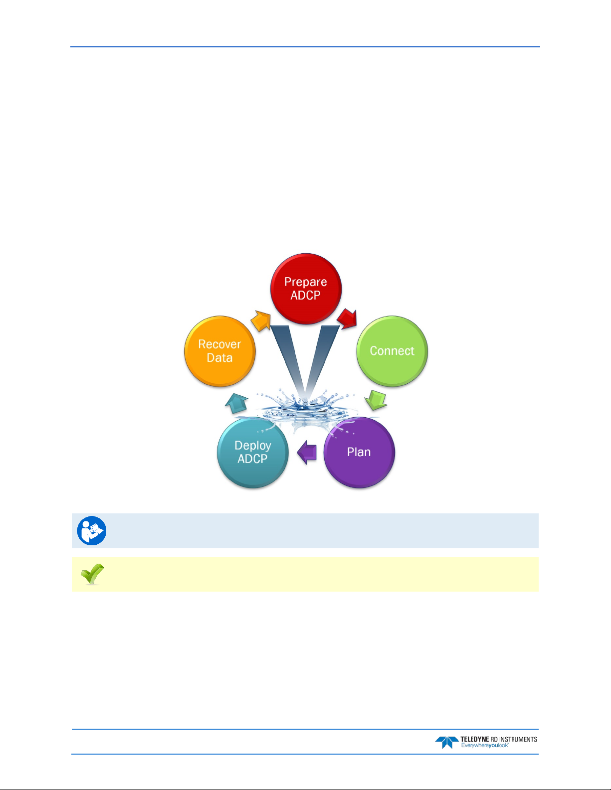
September 2017 Sentinel V SC and RT Operation Manual
ReadyV Interface Features
Onboard Software. The ReadyV software used to configure, deploy, and recover data is resident on the
ADCP. All that’s needed to communicate with the ADCP is a computer of opportunity and a web browser.
High-speed wireless data download. Wireless functionality allows quick data downloads and instrument re-
configuration. This feature also allows for wireless setup and software/firmware updates.
Intuitive Interface. ReadyV has a user-friendly interface for pre-deployment planning to configure the Sen-
tinel V for deployment, running all pre-deployment tests, and starting the deployment properly configured for the task at hand.
Onboard Maintenance Log. When was the last time the compass was calibrated? The batteries changed? O-
rings replaced? Now this information and more can be stored on the Sentinel V itself, for ready access
whenever connected to the instrument.
Read the Self-Contained Sentinel V Deployment Guide for step-by-step instructions for
deploying a SC system.
See the ReadyV Quick Start Card PDF file installed with the Documentation and Software CD.
Page 44
EAR-Controlled Technology Subject to Restrictions Contained on the Cover Page.
Page 61
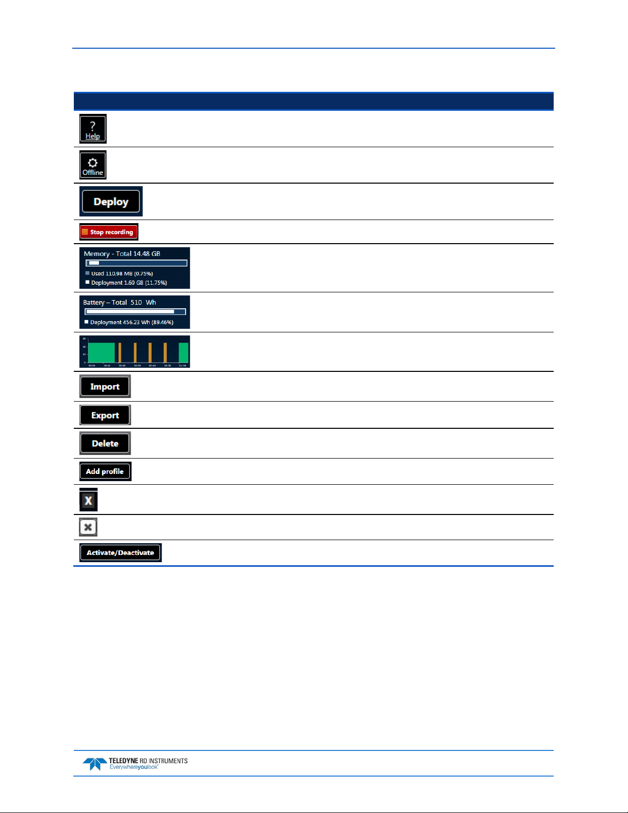
Sentinel V SC and RT Operation Manual September 2017
ReadyV uses the following icons and buttons:
Icon Description
Click on the Help button to display a help screen.
Click to download ReadyV. Once downloaded on the computer, unzip the file and double-click on
index.html to run ReadyV in the offline mode.
Once the deployment planning is complete, use the Deploy button to deploy the Sentinel V ADCP.
If the ADCP is deployed, click the Stop button to stop the deployment.
Displays the amount of recorder space.
Displays the amount of battery power needed for the deployment.
Displays an overview of the ensemble timing.
Click the Import button to load a scenario (*.txt) into ReadyV.
Click the Export button to save the scenario (*.txt) to the computer.
Click the Delete button to delete a scenario (*.txt).
Click to add a profile.
Click to delete a profile.
Click to close a panel.
Click the Activate/Deactivate button to add or remove features.
EAR-Controlled Technology Subject to Restrictions Contained on the Cover Page.
Page 45
Page 62

September 2017 Sentinel V SC and RT Operation Manual
Using the Home Panel
Once the computer is connected to the ADCP, the Home panel opens and shows an overview of the Sentinel V ADCP configuration.
Each section on the Home panel acts as a link the respected panel (Set sampling strategy, Review system,
Download data, System check, Review resources , and Deployment checklist). As the mouse is hovered
over a section, it will change to a lighter blue and the mouse pointer will change to the hand icon ( ).
Click to go to the panel.
You can adjust the screen and font size within the Internet Explorer® and Google Chrome® browsers.
Use Ctrl+ to increase zoom, Ctrl- to decrease the zoom level. If the mouse has a scroll wheel, use
Ctrl+mouse wheel to adjust the zoom level. Use Ctrl+0 (zero) to return to 100% zoom.
If the Zoom level on the browser is set higher than 100%, the right side of the ReadyV screen
may be partially cut off (see Solving Partially Cut Off Screen Issues).
Figure 9. Home Panel
While ReadyV is open and no keys are pressed for five minutes, an inactivity warning is displayed, and after
another five minutes of no keys being pressed the wireless connection is turned off on the ADCP.
To run ReadyV again and connect to the ADCP, then the internet browser page or the browser tab which was
running ReadyV must first be closed. Then restart the connection.
Page 46
EAR-Controlled Technology Subject to Restrictions Contained on the Cover Page.
Page 63

Sentinel V SC and RT Operation Manual September 2017
Using the ReadyV Panels
The panels on ReadyV may be accessed in any order. The recommended path to create a new scenario is
shown in Figure 10.
Figure 10. Creating a Scenario Flow Chart
Deployment scenario files are system specific – V20, V50, and V100 files can only be used on
the same frequency system.
EAR-Controlled Technology Subject to Restrictions Contained on the Cover Page.
Page 47
Page 64

September 2017 Sentinel V SC and RT Operation Manual
Creating and Saving Scenarios
To create a scenario:
1. Click anywhere on the Step 1 Set sampling strategy section on the Home panel.
2. Select a template using the drop-down list. The green checkmark icon indicates the currently selected scenario. Enter a name for the deployment and enter a description.
Selecting one of the templates will overwrite the settings. For example, selecting the Coastal
Mooring Template and clicking Save will save the scenario as Coastal Mooring with the
default settings from the template.
Changes are saved to the scenario whenever the Save button is selected.
Always use the Step1 Scenario panel to change the name of the scenario and add a
description for future use.
3. Use the Step 1 Set sampling strategy panels to adjust the scenario settings:
• Enter a name and description on the Step 1: Scenario panel.
• Click on the Step2 Settings panel to change how the system will be set up during the deployment.
• Click on the Step 3 Profiling panel to change how the water profile and timing will be set up dur-
ing the deployment.
• Use the resources overview to verify power and data recorder requirements for the deployment.
4. Click the Export button on the Step 1 Set sampling strategy panel to save the selected scenario
(*.txt) to the computer. On the Save As dialog, name the deployment scenario file (*.txt). Click
the Save button.
When saving a file in Safari®, the default file format is Web Archive. If you save the file with
this format type and try to import it, it will fail. Change the format type to Page Source to
save and import files correctly in Safari.
Page 48
EAR-Controlled Technology Subject to Restrictions Contained on the Cover Page.
Page 65

Sentinel V SC and RT Operation Manual September 2017
Although not recommended, *.txt files can be viewed with any ASCII/plain text editor such as
NotePad®.
Editing the *.txt file using a text editor will allow items that if set incorrectly can cause the
data to be bad and uncorrectable even in post processing.
Do not edit *.txt files in Microsoft Word®.
5. Click the Save button to save the scenario to the ADCP and return to the Home panel. If a measurement file with the same name already exists, it will be overwritten.
EAR-Controlled Technology Subject to Restrictions Contained on the Cover Page.
Page 49
Page 66

September 2017 Sentinel V SC and RT Operation Manual
Collecting Waves Data
Ensure that the Waves firmware feature is enabled. ReadyV will allow setting a waves
scenario, but if the feature is not enabled the data can not be processed.
To create a Waves scenario:
1. Click anywhere on the Step 1 Set sampling strategy section on the Home panel (see Figure 9) to
use a measurement template. Select the Waves + Cu r ren ts or Continuous Waves template
using the drop-down list.
2. Click the Save button to save the measurement scenario or Cancel to return to the previous settings. If a measurement file with the same name already exists, it will be overwritten.
3. Use the Step 1 Set sampling strategy panels to adjust the scenario settings:
• Click on the Step2 Settings panel to change how the system will be set up during the deployment.
• Click on the Step 3 Profiling panel to change how the water profile and timing will be set up dur-
ing the deployment. TRDI recommends using the Waves Profile setup.
• Use the resources overview to verify power and data recorder requirements for the deployment.
4. Verify the Ping interval is 0.5 seconds. Velocity can only process waves data collected at 2 Hz. The
Ping interval must be set to 0.5 s for Water Profile 1.
Velocity can only process waves data collected at 2 Hz.
5. Click the Export button on the Home panel to save the selected scenario (*.txt) to the computer.
On the Save As dialog, name the deployment scenario file (*.txt). Click the Save button.
6. Click the Save button to save the scenario to the ADCP and return to the Home panel.
Page 50
EAR-Controlled Technology Subject to Restrictions Contained on the Cover Page.
Page 67

Sentinel V SC and RT Operation Manual September 2017
Example Waves Setups
The Waves + Currents template samples Profile 1 at 2 Hz so that the noise floor can be
characterized with Profile 2 at 1hz.
The Continuous Waves template samples at 2 Hz.
If the deployment duration requires >30 days with a V100 system:
• Add an external battery case or Lithium battery
Or
• Reduce the number of wave pings/burst from 2100 to 1024 while keeping
the ping rate at 2 Hz (0.5 seconds/ping).
Reducing the burst duration should not be performed on any western ocean boundaries
where you have low frequency ground swell (i.e. Alaska to Chile on the pacific, or UK to Africa
To profile to a range less than 49.6 meters:
in the Atlantic). If you are on the eastern boundary of the ocean, a 1024 ping burst is
acceptable.
• Change the bin size to <1.2 meters.
To profile to a range of >99 meters, you must:
• Clear the ping collision error by setting the ping rate of the waves burst (Profile 2 only!) to 1.25
seconds
• With 1.25 seconds, the power consumption is much larger, suggestions are to:
o Add an external battery case or Lithium battery
o Further reduce the number of pings per wave burst to <1024 to allow 30 days
Version 1.5 of Velocity will “zero fill” the burst to deal with non-powers of 2 FFT lengths.
If you make changes to any of the Profile settings, the name of the profile will change to
Custom.
Opening a Saved Scenario
To open a saved Scenario:
1. Click anywhere on the Step 1 Set sampling strategy section on the Home panel.
2. To open a scenario, click the Import button. On the Open dialog, select the deployment scenario file (*.txt). Click the Open button.
3. Use the Step 1 Set sampling strategy panels to adjust the scenario settings if needed.
4. If changes are made, click the Export button to save the selected scenario (*.txt) to
the computer. On the Save As dialog, name the deployment scenario file (*.txt).
Click the Save button.
EAR-Controlled Technology Subject to Restrictions Contained on the Cover Page.
Page 51
Page 68

September 2017 Sentinel V SC and RT Operation Manual
Deleting a Saved Scenario
To delete a saved scenario from the list:
1. Click anywhere on the Step 1 Set sampling strategy section on the Home panel.
2. Click the Delete button to open the Delete Scenarios panel. Note that the active
scenario will not appear on the list of scenarios to delete.
3. Select the scenario to be deleted and click Delete.
4. Click the Delete button on the message box to delete the saved scenario from the list.
The active scenario and factory included scenario templates cannot be deleted.
To delete the active scenario, first select another template/scenario, click the Save button,
and then repeat the process to delete the scenario.
Once the Delete button is clicked, the scenario file is deleted and cannot be recovered.
5. Click the Close button to exit the Delete scenario panel.
Page 52
EAR-Controlled Technology Subject to Restrictions Contained on the Cover Page.
Page 69

Sentinel V SC and RT Operation Manual September 2017
Using the Set Sampling Strategy Panels
Click anywhere on the Step 1 Set sampling strategy section on the Home panel to open the Sampling
strategy panel.
Figure 11. Set Sampling Strategy Panels
EAR-Controlled Technology Subject to Restrictions Contained on the Cover Page.
Page 53
Page 70

September 2017 Sentinel V SC and RT Operation Manual
Error Messages
While entering parameters, if a value is entered outside the normal range, an error message appears. For
example, entering 0.4 meters for the cell size displays an error because the cell size is too small. The error
must be corrected before the setting can be saved.
Scenarios with two water pings may have a ping collision error. To clear a ping collision, change the time
between pings to the recommended value and then change the time between profile groups so that there is
enough time for profile type 1 to finish before profile group 2 starts.
Step 1: Scenario
Use the Scenario setting panel to name the scenario and enter a description. Click Save on the Step 1 Set
sampling strategy panel to save the settings or Cancel to return to the previous settings.
When a scenario is first created, it will use a default name. For example, selecting the Coastal
Research (Template) and clicking Save will save the scenario as Coastal Research (see
Name – Enter the name of the deployment scenario.
Description – Enter a description of the deployment scenario.
Creating and Saving Scenarios). Make sure to change the name of the scenario and add a
description for future use.
Page 54
EAR-Controlled Technology Subject to Restrictions Contained on the Cover Page.
Page 71

Sentinel V SC and RT Operation Manual September 2017
Step 2: Settings
Use the Step 2: Settings panel to change how the system will be set up during the deployment. Click Save
on the Step 1 Set sampling strategy panel to save the settings or Cancel to return to the previous settings.
ADCP depth – Enter the depth of the ADCP. The ADCP uses depth in its speed of sound calculations. If the
pressure sensor is not available, then the ADCP will use this manual depth setting.
Salinity – Enter the salinity of the water. Fresh water is 0 and salt water is typically 35. Salinity is used to
calculate the speed of sound. The speed of sound is used by the ADCP to scale the velocity data properly. If
0 is entered when deployed in 35 salinity water, the data will have a 3% velocity estimate error.
Magnetic variation – Enter the angle between true north and magnetic north. By convention, declination is
positive when magnetic north is east of true north and negative when it is to the west. This angle varies
depending on position on the Earth’s surface, and changes over time. The compass default is to output
magnetic heading.
For the greatest accuracy, TRDI recommends checking the National Geophysical Data Center
website (below) to find the declination angle based on the latitude and longitude:
http://www.ngdc.noaa.gov/geomagmodels/Declination.jsp
Heading adjustment – Corrects for a physical misalignment between the ADCP’s Beam 3 and the heading
reference. Enter the heading alignment angle (referenced to Beam 3) used as a new zero reference for
heading output.
Serial Port – If the ADCP includes the real-time serial output data feature, select the Serial port Baud
rate from the drop-down list. See Using Real-Time Serial Data Output for details on cable connections.
Using a low baud rate will impact the Ping interval. The time between pings needs to be
sufficient to allow time for the data to be output through the serial port before the next ping.
If you see an error message, increase either the Baud rate or the Ping interval.
Using Real-Time Serial Data Output
There is no command and control on the serial port on firmware version: 47.xx. The only
command and control is through the deployment Web software application ReadyV. For
The V Series Self-Contained ADCP can include an optional real-time serial data output. This feature must
be configured when the system is ordered. The output format is PDO and will be single ping ensembles of
beam coordinate profiles with no screening. Use Sentinel V RT Utilities or your own software to capture
the data to a file as it is output by the Sentinel V. Use the Velocity software to properly screen, transform,
and average the data just like data collected on the recorder.
To use the real-time serial data output:
1. Review the Serial Port Application Notes
mended High Perfo r ma nce settings.
command and control through the serial port, see Switching RT and SC Modes and
Connecting to the Sentinel V Real-Time.
and set the computer’s power options to the recom-
EAR-Controlled Technology Subject to Restrictions Contained on the Cover Page.
Page 55
Page 72

September 2017 Sentinel V SC and RT Operation Manual
2. Remove the dummy plug and connect the Y-mold cable to the Sentinel V.
3. Connect the I/O cable Serial connector to your computer. See Figure 32 page 82 for wiring.
4. Connect the AC Power Adapter output cable to the Y-mold cable.
5. Connect the AC Power Adapter line cord to a 110 to 240VAC, 50 to 60Hz power input.
6. When power is applied, you should hear a long beep, a 10 to 15 second delay, and then a short
beep. If you do not hear the beeps, check the cable connection and power before continuing.
7. Connect wireless to ReadyV (see Using the Wireless Connection
).
8. On the ReadyV Sampling strategy panel, adjust the baud rate and timing as needed (see Serial
Port Baud Rate).
Using a low baud rate will impact the Ping interval. The time between pings needs to be
sufficient to allow time for the data to be output through the serial port before the next ping.
If you see an error message, increase either the Baud rate or the Ping interval.
9. Install Sentinel V RT Utilities if needed. A copy of RDI Tools is included on the Sentinel V Software and Documentation CD.
10. Start Sentinel V RT Utilities. On the Connect To screen, select WorkHorse. Select the COM
Port that the Sentinel V ADCP serial cable is connected to. Click Next.
Page 56
EAR-Controlled Technology Subject to Restrictions Contained on the Cover Page.
Page 73

Sentinel V SC and RT Operation Manual September 2017
11. Enter the Baud Rate to match what is set in the ReadyV Timing panel, Parity to None, Stop
Bits to 1, and Flow Control to None. Click Next.
12. Uncheck all boxes. Click Finish.
13. Press F3 and create a log file. Name the file and use *.pd0 (pd zero, not the letter 0) for the file
extension.
14. Use ReadyV and deploy the ADCP.
15. Process the data file with the Velocity software.
Serial Port Application Notes
Serial Port Command and Control – There is no command and control on the serial port on Firmware Version: 47.xx. The only command and control is through the deployment Web software application
ReadyV. For command and control through the serial port, see Connecting to the Sentinel V Real-Time
Serial Port Data Output Format – The data being output is PD0. The data in this file will be single
ping ensembles of beam coordinate profiles with no screening (i.e. no screening for fish rejection, correlation, error velocity). To create screened earth coordinate average ensembles, TRDI recommends that you
play back the data through the TRDI Velocity software program.
Computer Power Options – Set the computer’s power options to High Performance to reduce lost
pings and lost communication issues when the computer sleeps. Use the Control Panel, Hardware
and sound, Power Options screen. Click the drop-down list to view the hidden additional plans and
select the High Performa nce setting (see Figure 12).
.
EAR-Controlled Technology Subject to Restrictions Contained on the Cover Page.
Page 57
Page 74

September 2017 Sentinel V SC and RT Operation Manual
Figure 12. Recommended Computer Power Options Setting for Real-Time Serial Data Output
Serial Output Baud Rate – Using higher baud rates will allow for faster pinging. However, higher baud
rates are more susceptible to noise and results in poor communica tio ns. Therefore, it is highly rec o mmended when using cables 25m and longer that you use RS422 communications (instead of RS232 communications) or use a baud rate of 9600 or lower.
It may not be possible to use RS232 communications with long cables (>50m) and therefore
you should test your communications setup with the actual cable you intend to use before
you deploy.
The serial port type, RS232 or RS422, is determined at the time of purchase. If you are not
sure which type of serial port you have or if you wish to change from RS232 to RS422 then
please contact our Field Service department at rdifs@teledyne.com.
Serial Output Timing – Enabling the serial output will add time to the completion of an ensemble. Depending on the time between pings (ensembles) it may not be possible for the ADCP to output the serial
data string before it is supposed to start the next ping. If this condition occurs, then the ADCP will skip
the ping that was to occur and will start the next ping at the interval timing that you have requested.
If you setup the ADCP to have a ping rate of 2hz and greater with a number of depth cells
(bins) greater than 50 then it is possible that the ADCP will not be able to respond to the
touch sensor. This occurs because the ADCP is not able to sense that the touch sensor
interrupt has been enabled. In order to recover from this condition it will be required for you
to remove the power from the instrument completely for a period of 60 seconds. Once you
connect the power you will need to “press” the touch sensor within 15-30 seconds so that
the touch sensor will be latched and the ADCP will allow you to establish communications
through the ReadyV deployment software and stop the deployment.
Power Consumption – Enabling the serial output will increase the ADCP’s power consumption. This
additional power is included in the planning software ReadyV. It is not possible to exactly determine the
effect of certain setups and therefore TRDI recommends that you include a 10% safety for deployments
that have ping rates of less than 1 second.
Data Recorder and Serial Communications – The Sentinel V will always have the recorder card enabled whether you have serial communications enabled or disabled. If the recorder card fills up during
your serial port operations, the Sentinel V will continue to operate and send out serial data. If you stop the
deployment (through ReadyV) and the recorder card is full, you will not be able start data collection without first deleting the data file (you can elect to download the data first or not).
Page 58
EAR-Controlled Technology Subject to Restrictions Contained on the Cover Page.
Page 75

Sentinel V SC and RT Operation Manual September 2017
Step 3: Profiling
Use the Step 3: Profiling panel to change how the water profile will be set up during the deployment. The
Sentinel V ADCP can have two different water profiles. Each water profile can be set independently. If
there is one water profile, the Add profile button appears. If there are two water profiles, click the white X (
) to delete the second water profile. Click Save on the Step 1 Set sampling strategy panel to save the set-
tings or Cancel to return to the previous settings.
Select profile – Use the drop-down list to select a water profile from the list. Each water profile can use a
default setup or select a predefined profile. If you make changes to any of the settings, the name of the
profile will change to Custom.
If the data file is collected with two water profiles, Profile 1 and Profile 2 are considered compatible for
merging when post-processing the data file with the Velocity software if the following are all true:
• Number of cells matches
• Cell size matches
• Blank matches
• Both either have vertical beam OR both do not have vertical beam selected
• Bandwidth must be the same for both profiles
The Standard deviation shows the expected standard deviation of the velocity data stored in
each ensemble being collected by the Sentinel V ADCP. Most users will want to minimize this
value so that they obtain the best data possible (i.e. data containing the least amount of
noise). Standard deviation is dependent on cell size, the Number of pings, Ambiguity velocity,
and the Bandwidth
Time between ensembles – Select a time between ensembles from the drop down list. Time is based on the
start of one ensemble to the start of the next ensemble. When two water profiles are used, set the Offset
between Profile groups time to avoid ping collisions.
Time between ensembles applies to both water profiles.
Range – Select the range to measure. The default value shown in Table 3 is based on typical range possible
based on the system frequency. The actual maximum range is dependent on the absorption in the water
EAR-Controlled Technology Subject to Restrictions Contained on the Cover Page.
Page 59
Page 76

September 2017 Sentinel V SC and RT Operation Manual
based on the Sentinel V ADCP frequency, the water salinity, water temperature and the actual deployment
depth of the ADCP.
Cell size – Sets the cell size. Adjust the cell size as necessary as recommended in Table 3. A larger cell size
decreases the standard deviation, but shallow water situations may need to use smaller cells to gather
more data points.
It is not recommended to set the cell size below the minimum or above the maximum range
shown in Table 3.
Blank – Moves the location of the first cell away from the Sentinel V ADCP transducer head to allow the
transmit circuits time to recover before the receive cycle begins. The default value is based on system frequency and it is highly recommended to use this value. Setting a value below the default blank distance
may show ringing/recovery problems in the first depth cells.
It is not recommended to set the blank below the default value shown in Table 3.
Table 3. Blank Distance, Range, and Cell Size
System Blank Distance (Default) Range (Default) Cell Size (Default (Min – Max))
Sentinel V 100m (307.2kHz) 1.6m 100m 4m (1m - 6m)
Sentinel V 50m (491.52kHz) 1.0m 50m 2m (0.6m - 4.8m)
Sentinel V 20m (983.04kHz) 0.4m 20m 1m (0.3m - 2.4)
Number of cells – Sets the number of depth cells. The value will be calculated based on the Range and Cell
size.
First Cell – The range from the transducer face to the middle of the first cell. The Cell size and the Blank pri-
marily affect where it is located.
Number of pings – Adjust the number of pings to gather the desired Standard Deviation. To increase the
expected accuracy of the velocity measurement (reduce the Standard Deviation), increase either the number of pings, cell size, or both.
Ping interval – Sets the time per ping.
Ambiguity velocity – Ambiguity velocity represents the maximum relative velocity (Sentinel V ADCP mo-
tion plus the maximum actual water velocity) the ADCP can measure along a beam. Select one of the settings from the drop-down list. This must be set correctly to avoid ambiguity errors. Ambiguity velocity is
used to improve the standard deviation: The lower the value of the ambiguity velocity, the lower the single-ping standard deviation.
Bandwidth – Sets the profiling bandwidth and sampling rate. Smaller bandwidths allow the ADCP to pro-
file farther, but the standard deviation is increased by as much as 2.5 times.
Bandwidth Sample rate Standard deviation Profiling range
High (25%) High Low Low
Low (6.25%) Low High High
Standard deviation – This shows the expected standard deviation of the velocity data stored in each
ensemble being collected by the Sentinel V ADCP. Most users will want to minimize this value so that they
obtain the best data possible (i.e. data containing the least amount of noise). Standard deviation is dependent on cell size, the Number of pings, Ambiguity velocity, and the Bandwidth.
Enable vertical profile – Check this box to enable the vertical beam profile.
Page 60
EAR-Controlled Technology Subject to Restrictions Contained on the Cover Page.
Page 77

Sentinel V SC and RT Operation Manual September 2017
The Vertical Beam Feature is optional. Contact your local sales representative if you are
interested in upgrading your system.
See Activating Features for instructions on how to activate/deactivate features.
Using the Review System Panel
The System panel shows an overview of the Sentinel V ADCP configuration. Click on the Step 2: Review
system panel to open the Review system panel as shown below.
• Use the Sensor data panel to display the sensor values
.
• Use the Feature control panel Activate/Deactivate button to activate or deactivate features.
Figure 13. Review System Panel
Activated features will have a green under Feature control. Deactivated features will have
a red X.
See Activating Features for instructions on how to activate/deactivate features.
EAR-Controlled Technology Subject to Restrictions Contained on the Cover Page.
Page 61
Page 78

September 2017 Sentinel V SC and RT Operation Manual
Sensor Data
This section shows the raw pitch, roll and heading as received by the internal sensor. Temperature, depth
and speed of sound are also displayed.
Figure 14. Pitch, Roll and Heading
Heading - When Beam 3 is pointed toward magnetic north, heading = 0°. If a he a din g bias
of the local
declination is applied, then the heading will be true north.
Pitch (Tilt 1) - When the unit is pointed up or down, pitch = 0°. When the unit is on its side, pitch =
±90° (see Figure 15).
Roll (Tilt 2) - When the unit is pointed up or down, roll = 0°. When the unit is on its side, roll = ±90°
(see Figure 16).
Page 62
EAR-Controlled Technology Subject to Restrictions Contained on the Cover Page.
Page 79

Sentinel V SC and RT Operation Manual September 2017
Raw (unprocessed) Pitch (Tilt1) and Roll (Tilt2) will behave as follow:
Figure 15. Raw Pitch
Figure 16. Raw Roll
The following table describes the sign convention for the Pitch and Roll:
Sign of Angle for a Unit Facing Up Down
Pitch (Tilt 1) - Beam 3 higher than Beam 4 + +
Roll (Tilt 2) - Beam 2 higher than Beam 1 + -
EAR-Controlled Technology Subject to Restrictions Contained on the Cover Page.
Page 63
Page 80

September 2017 Sentinel V SC and RT Operation Manual
Activating and Deactivating Features
Use the Activate/Deactivate button to add or remove features on the Sentinel V.
Features can only be activated or deactivated when connected to the ADCP and require a
license file (*.lic) that is tied to the ADCP’s serial number.
Contact your local sales representative if you are interested in upgrading your system.
To activate or deactivate a feature:
1. Save the SVnnnnn.lic file (when nnnnn is the ADCP serial number) on your computer.
2. Start ReadyV.
3. Click on the Step 2: Review system panel to open the Review system panel. Click on Feature
control and then click the Activate/Deactivate button.
Features ordered with the system will be activated by TRDI.
Save the *.lic file in a folder that has full read/write permissions. For example, if you save the
file to the AppData folder, you may get a file load error.
Feature upgrades must be installed in each mode to be available for dual-application use. See
Installing Feature Upgrades for RT mode. If you purchased the feature for one mode, contact
TRDI field service to receive the feature for the other mode.
4. Select the feature(s) to be activated or deactivated.
5. Click the Save button.
6. On the Open dialog, locate the *.lic file.
7. Click the Open button. The feature is now activated. Repeating this process will deactivate the
feature.
Figure 17. Activating and Deactivating Features
Page 64
EAR-Controlled Technology Subject to Restrictions Contained on the Cover Page.
Page 81

Sentinel V SC and RT Operation Manual September 2017
Using the Download Data Panel
Use the Download Data panel to check the status of data files, recover data, and erase the recorder. To select a data file, click on it. Click on the Step 3: Download data panel to open the Recorder panel as shown
below.
Figure 18. Download Data Panel
If there are 50 or more data files on the recorder, it is best to download and then delete the
files before deploying the ADCP.
Status – Closed or Recording. To close a file, click Stop (see Starting or Stopping Deployments).
If a data file status is recording, the Delete and Download buttons do not appear.
Name – Shows the file name.
Size – Shows the file size.
Start Date – Shows the date and time the data file was created.
Stop Date – Shows the date and time the data file was closed.
EAR-Controlled Technology Subject to Restrictions Contained on the Cover Page.
Page 65
Page 82

September 2017 Sentinel V SC and RT Operation Manual
Duration – Shows the duration of the data file.
Download – Click on a data file to select it. Click the Download button to save the data file to a folder on
the computer. For Windows 7®, click on the triangle next to the Save button to select the folder where
the data will be written.
If the Save File dialog box does not appear, make sure you are using a supported browser
(see Table 1, page 7).
Delete – Click on a data file to select it. Click the Delete button to delete the selected data file. Enter the
code and then click the Delete button at the prompt. Once erased, the data is not recoverable.
Format recorder – Click the Format recorder button to delete all data files. Enter the code and then click
the Format button at the prompt. Once erased, the data is not recoverable.
Page 66
EAR-Controlled Technology Subject to Restrictions Contained on the Cover Page.
Page 83

Sentinel V SC and RT Operation Manual September 2017
Using Download Managers
Based on the deployment setup parameters such as ping interval, number of bins, etc., and the duration of
the deployment, the size of the data file to be downloaded from the Sentinel V ADCP can be in the order of
gigabytes. While downloading a large data file from the Sentinel V, the user may close the browser by mistake or the ADCP may disconnect. In order to recover the data file download from such situations, TRDI
recommends using a FireFox® download manager add-on called FlashGot®. This add-on will help resume downloads from the last point where the partial download left off. Using FlashGot, users may also
configure the maximum download speed using any internal and most external download managers.
Although ReadyV file downloads will work on most external download managers and most
browsers (see Computer Considerations for supported platforms), TRDI recommends using
Once FlashGot® is installed; when a data file is downloaded the following popup is observed:
the latest version of Firefox® (http://www.mozilla.org/en-US/firefox/new/) and the FlashGot®
plugin (https://addons.mozilla.org/en-US/firefox/addon/flashgot/developers).
Select the FlashGot option and click OK to download the file.
It may be noted that even though there are FlashGot extensions and plugins for other
browsers such as Google Chrome® etc., TRDI has not tested the efficacy of the FlashGot
plugin in other browser environments.
EAR-Controlled Technology Subject to Restrictions Contained on the Cover Page.
Page 67
Page 84

September 2017 Sentinel V SC and RT Operation Manual
Using the System Check Panel
The System checks pane l keeps track of when maintenance items were performed on the ADCP and saves
log files
. Click on the Step 4: System check panel to open the System check panel as shown below.
Figure 19. System Check Panel
Click a panel to select a maintenance item:
• Update Firmware – this starts the firmware update
• System Built-in Tests – Use this to run the built -in tests on the Sentinel V ADCP. The built-in tests
can help isolate problems to a major functional area of the Sentinel V ADCP.
• Compass – this starts the compass calibration procedure.
• Pressure Sensor – click this to zero the pressure sensor. Zero the pressure sensor before every de-
ployment.
• Battery – click this button to set the date that the battery was replaced. Replace the battery be-
fore every deployment.
• System clock – Click this button to set the Sentinel V ADCP’s clock.
• O-Ring – click this button to set the date that the O-Ring was replaced. The O-ring(s) should be
replaced whenever the system is opened.
• Desiccant – click this button to set the date that the desiccant was replaced. The desiccant should
be replaced whenever the system is opened.
Page 68
EAR-Controlled Technology Subject to Restrictions Contained on the Cover Page.
procedure.
Page 85

Sentinel V SC and RT Operation Manual September 2017
• Silicone Oil – click this button to set the date that the silicone oil was replaced. The oil should be
checked whenever the system is ready for a deployment.
• Battery Springs – click this button to set the date that the battery springs were replaced. The
springs should be checked whenever the individual D cell batteries are replaced.
• Factory Maintenance – this button shows a report of the factory maintenance performed. It will
be updated once serviced by TRDI. Based on experience, TRDI knows that most ADCPs need to
have the urethane inspected after two to three years of field use. Many users are not familiar with
the early signs of urethane failure. The primary damage to the urethane is from bio-fouling and
long exposure to the water and sun. Damage occurs on the surface of the urethane and at the
edge where the urethane bonds to the cups. By returning the system every two to three years,
TRDI can inspect it for early signs of urethane failure and repair it through our Factory Maintenance Service. At the same time, TRDI will make any necessary upgrades to boards, assemblies,
and firmware. This routine service period, proper care, and general maintenance ensures optimal Sentinel V ADCP performance.
Installing Firmware Upgrades
To install a firmware upgrade:
1. Download the firmware from TRDI’s website customer care page:
http://www.rdinstruments.com/support/software-firmware
puter and unzip the file. The file will be sv_47xx.xx.xx.xx.bin format where xxxx = firmware version.
, item 59. Save the file to the com-
2. Connect to the Sentinel V ADCP.
3. On the System checks panel, select Update firmware.
Figure 20. Updating the Firmware
4. Click the Browse file button and locate the firmware file sv_47xx.xx.xx.xx.bin file downloaded in
step 1. Select the file and click Open.
5. The firmwar e wil l ins t al l.
6. Once the firmware update is complete, the ADCP will reboot. Close the browser and
reconnect the
wireless connection to connect to the ADCP.
7. If the new firmware does not install, contact Customer Service.
EAR-Controlled Technology Subject to Restrictions Contained on the Cover Page.
Page 69
Page 86

September 2017 Sentinel V SC and RT Operation Manual
ReadyV Log Files
ReadyV creates several log file s. Cl ick the corresponding button to save a copy of the log file. The maintenance log files can be opened with any text editor.
Log file name Description
Use the Save maintenance log button to create a text file (*.txt) with the date and time maintenance items
were completed.
The Save diagnostic log is intended for the TRDI engineers to debug issues that may be happening on the
instrument. The log file will be saved in a *.tar format and can be e-mailed to TRDI engineers to aid in
troubleshooting the instrument.
Use the Clear fault log button to clear the fault log of all previous entries.
Using the Review Resources Panel
The Resources panel displays the power and data recorder requirements for the deployment. Click on the
Step 5: Review resources panel to open the Review resources panel as shown below.
Figure 21. Review Resources Panel
Duration – Enter the expected duration of the deployment from the time of the first measurement ping
(either immediately or delayed). This duration does not instruct the Sentinel V ADCP to stop data collection; it is for estimating the battery usage and storage required. Click the Update button and review the
resources panel.
Power source – Select Battery or Unlimited external as the power source. If Battery is selected, use
the drop-down list to select the battery type from the list and enter a number in the External battery
Page 70
EAR-Controlled Technology Subject to Restrictions Contained on the Cover Page.
Page 87

Sentinel V SC and RT Operation Manual September 2017
cases box if you will use an external battery case. If you are using a Lithium battery pack, select Custom
and then enter the available watt hours in the Custom power box. A fresh Lithium battery pack has
1900 Wh available. Click the Update button and review the resources panel.
EAR-Controlled Technology Subject to Restrictions Contained on the Cover Page.
Page 71
Page 88

September 2017 Sentinel V SC and RT Operation Manual
Using the Deployment Checklist Panel
The Deployment checklist panel starts or stops the deployment. Click on the Step 6: Deployment checklist
panel to open the Deployment checklist panel as shown below.
Figure 22. Deployment Panel
Select Now or Later:
• Now – The Sentinel V ADCP will start pinging as soon as the Deploy button is clicked.
• Later – Selecting the Later button and entering a date and time in this field enables a delay from
the start of a deployment to the first water profiling ping. The Sentinel V ADCP will sleep from
the time the Deploy button is clicked until the set time arrives.
Deployment checklist:
• Built-in Tests – The Built-in tests should be run
• Compass – The compass should be calibrated before deploying the system.
• Pressure sensor – The pressure sensor should be zeroed before deploying the system.
• Battery – The battery should be replaced before deploying the system.
• Silicone oil – The oil should be filled before deploying the system.
• System clock – The clock should be set before deploying the system.
before deploying the system.
Page 72
EAR-Controlled Technology Subject to Restrictions Contained on the Cover Page.
Page 89

Sentinel V SC and RT Operation Manual September 2017
Starting or Stopping Deployments
To start a deployment:
1. Click on the Step 6: Deployment checklist panel to open the Deployment checklist panel.
2. On the Deployment checklist panel, click the Deploy button to start the ADCP pinging.
3. On the Home panel, verify that is shows the Stop Recording button.
4. Close the browser page.
To stop a deployment, click the Stop recording button.
EAR-Controlled Technology Subject to Restrictions Contained on the Cover Page.
Page 73
Page 90

September 2017 Sentinel V SC and RT Operation Manual
Running ReadyV Offline
ReadyV can be used without requiring access to the Sentinel V ADCP once it is downloaded. The Step 1:
Set sampling strategy panel is used to set the Sentinel V ADCP configuration (see
Strategy Panels). When running offline, the user must select the Sentinel V ADCP model number, battery
type, and deployment duration.
To run ReadyV offline:
Using the Set Sampling
1. Connect
to the Sentinel V ADCP and click on the Offline button. Click Download ReadyVPlus
Offline App.
2. Select a location to download the file. Unzip the file. To start the app, double-click on index.html.
When the ADCP’s firmware is updated, delete older offline versions of ReadyV.
3. Click on Please select a predefined template. Use the Import and Export buttons to open
and save scenario*.txt files. See Creating and Saving Scenarios
for details.
4. Click on Step 2: Review system panel. Select the ADCP type from the drop-down list.
5. Click on Step 3: Review resources panel. Select the power source and deployment duration.
Page 74
EAR-Controlled Technology Subject to Restrictions Contained on the Cover Page.
Page 91

Sentinel V SC and RT Operation Manual September 2017
Chapter 3
INSTALLATION
In this chapter, you will learn:
• How to attach the handle
• How to connect/disconnect the I/O cable
• How to connect the optional external batter case
• How to use the real-time serial data out
• Cable wiring diagrams
• Available mounts for the Sentinel V
This chapter applies to both Sentinel V Self-Contained and Sentinel V Real-Time systems.
EAR-Controlled Technology Subject to Restrictions Contained on the Cover Page.
Page 75
Page 92

September 2017 Sentinel V SC and RT Operation Manual
Attaching the Handle
The handle makes it easier to carry the Sentinel V ADCP.
To attach the handle:
1. Thread the ends of the handle through the slots on the end-cap.
2. Use the snap-links to attach the handle to the Sentinel V ADCP.
Figure 23. Handle
Transducer Cover
The Sentinel V ADCP is shipped with a transducer cover to protect the transducer faces.
The transducer cover must be removed before deployment in order to collect good data.
Use the cover when the Sentinel V ADCP is in storage or is being handled.
Figure 24. Transducer Cover
Page 76
EAR-Controlled Technology Subject to Restrictions Contained on the Cover Page.
Page 93

Sentinel V SC and RT Operation Manual September 2017
Poor Design
Good Design
Mounting the Instrument
The preferred method of mounting the Sentinel V is using clamps that grip the circumference of the housing. The fallback method of mounting the instrument is to use the holes on the end-cap. See the
Installation Drawings for dimensions.
When clamping the Sentinel V to a mount, the clamp must not have a large gap between the front and rear
clamp. Using this type of design can cause the housing to deform or even break if the clamps are over
tightened. This will cause the ADCP to flood.
Design clamps that fully surround the housing. Design the gap as small as possible so that when the clamp
is fully tightened it will not deform the housing or cause excessive pressure on the housing.
Outline
Figure 25. Mounting the Instrument
Figure 26. Example Sentinel V End-Cap Mount
Use M6x1.0 bolts.
Only use stainless steel hardware.
The maximum thru-hole diameter in the mounting plate is 6.85 mm (0.270 inch). Using a
larger thru-hole could result in the threaded metal inserts on the end-cap being pulled out of
the plastic end-cap.
EAR-Controlled Technology Subject to Restrictions Contained on the Cover Page.
Page 77
Page 94

September 2017 Sentinel V SC and RT Operation Manual
Photo Credit: Mark Hegarty
General Manager Oceanographic and Hydrographic
Figure 27. Gimbal Bottom Mount
The end-cap mounting holes can also be used to attach a lead counter-weight to the ADCP when used in a
gimbal bottom-mount that holds the ADCP housing. The lead dampens the ability of the instrument to
just swing back and forth in the currents. Some movement is required, but the ADCP should not be freely
swinging. TRDI recommends using a torque on the M6 helicoils of no more than 5.6 Newton-meters (50
pound-inches) and maximum lead weight of 25 kg (55 lb.).
Photo Credit: James Cappellini
Mooring Systems, Inc.
Page 78
EAR-Controlled Technology Subject to Restrictions Contained on the Cover Page.
Page 95

Sentinel V SC and RT Operation Manual September 2017
WorkHorse to Sentinel V Mount Adapter
TRDI has designed two adapters to use an existing WorkHorse mount with the Sentinel V. The
81D-5000-xx adapter (where xx is available for different length housings) includes sleeves to make the
Sentinel V fit into a clamp designed for Workhorse ADCPs. The rubber sleeves are textured on one side to
provide a better grip on the ADCP and include adhesive on the other side so that the customer can either
glue it to the instrument or their clamp. The 81D-5001 kit is a delrin plate with WorkHorse end-cap hole
pattern. See the Outline Installation Drawings
for Sentinel V dimensions.
Figure 28. 81D-5000 Mounting Clamp Adapter Kit
Figure 29. 81D-5001 End-Cap Mounting Plate Adapter Kit
EAR-Controlled Technology Subject to Restrictions Contained on the Cover Page.
Page 79
Page 96

September 2017 Sentinel V SC and RT Operation Manual
Connecting Cables and Dummy Plugs
Sentinel V ADCPs can be purchased with the optional end-cap connector using either the right-angle or
straight connectors.
The dummy plugs should be installed any time the cable is removed. Use the dummy plug
when the Sentinel V ADCP is in storage or is being handled.
To Disconnect the Cable or Dummy Plug:
1. Turn the locking sleeve counterclockwise until it is fully loose and slides back.
2. Grasp the cable or dummy plug close to the housing and pull the cable or dummy plug straight out
away from the connector.
Figure 30. Removing the End-Cap Connector 8-Pin Dummy Plug
To Connect the Cable or Dummy Plug:
1. Spray lubricant on the rubber portion of the connector pins. This will help seat the conne ct o r.
Use light amounts of aerosol silicone (dry type) lubricant (such as from 3M) to help seat
the cable connectors and to protect the neoprene rubber from deterioration. Regular
lubrication is required.
2. Insert the dummy plug / cable onto the connector, rotating it until the keyed portions are properly
aligned. While keeping a slight inward pressure on the cable connector and ensuring that the connector is straight, thread the locking sleeve onto the receptacle to complete the connection.
Do NOT use any tools to tighten the locking sleeve ring. It should only be “finger tight”.
Page 80
EAR-Controlled Technology Subject to Restrictions Contained on the Cover Page.
Page 97

Sentinel V SC and RT Operation Manual September 2017
Using the AC Power Adapter
The AC Adapter runs on any standard AC power and supplies +18 VDC, 24 watts to the ADCP. The Sentinel V batteries can be connected or disconnected. If the adapter’s input voltage is greater than the battery
voltage, then the ADCP will draw all power from the AC adapter even if the battery is installed and connected. Use the AC Adapter when testing the ADCP to conserve the battery power.
The voltage specification of the Sentinel V battery pack is 18V; however, most new batteries
provide a slightly higher voltage. The AC power adapter used for powering the Sentinel V
operates at 18V and therefore if a system is connected to the AC power adapter and
simultaneously the batteries are connected, the batteries will be depleted until they reach
the same voltage as the AC power adapter. While this does not affect the operation of the
system, you should be aware of the loss of power that can occur. Once the batteries are
discharged to the supplied voltage of the AC power adapter supply, the batteries will no
longer be depleted.
If the batteries are above 18V and you wish to preserve the battery charge your options
would be:
• Disconnect the battery pack when using the AC power adapter.
• Use the banana plug cable 73D-6021-00 to power the unit with a different power
supply (voltage not to exceed 20V). Note: You will also need cable (73D-3112-XXX;
where XXX denotes the cable length in meters). Both cables indicate a max voltage
of 18V. In this case you can use the cables at 20V.
Figure 31. Using the Real-Time Serial Output and AC Power Adapter
Data common and power ground should not be shared in order to avoid creating a ground
loop in water that can cause corrosion.
EAR-Controlled Technology Subject to Restrictions Contained on the Cover Page.
Page 81
Page 98

September 2017 Sentinel V SC and RT Operation Manual
Cable Wiring Diagrams
This section has information on ADCP cabling. Custom configurations may not be shown here.
Figure 32. 73D-3112 – Underwater Y-Mold Cable Serial Cable with 8-pin Connector
Page 82
Figure 33. 73D-3113 – Underwater Y-Mold Cable Ethernet Cable
Figure 34. 73D-3101 – External Battery Case Cable with 8-pin Connector
EAR-Controlled Technology Subject to Restrictions Contained on the Cover Page.
Page 99

Sentinel V SC and RT Operation Manual September 2017
Connecting the External Battery Case
Sentinel V ADCPs can be purchased with the optional end-cap connector and an external battery case.
The dummy plugs should be installed any time the external battery case cable is removed.
Use the dummy plugs when the Sentinel V ADCP is in storage or is being handled.
To connect the external battery case:
1. Verify that both battery packs are connected (see Replacing the External Battery Case Packs
).
2. Remove the dummy plugs on the Sentinel V and external battery case (see Connecting Cables and
Dummy Plugs).
3. Connect the external battery case cable.
Figure 35. Connecting the External Battery Case
To avoid affecting the compass, place the external battery case at least 30cm (11.8 inches)
away from the Sentinel V ADCP.
The External Battery Case holds two battery packs that are shipped inside the case but not
connected. Connect BOTH batteries and seal the external battery case before deployment. It
is necessary to remove the top battery in order to connect the bottom battery cable. See
Replacing the External Battery Case Packs for details.
EAR-Controlled Technology Subject to Restrictions Contained on the Cover Page.
Page 83
Page 100

September 2017 Sentinel V SC and RT Operation Manual
Using Bottom Mounts
Bottom mounts can range from simple PVC frames to Trawl Resistant Bottom Mounts. Below is an example of some of the types of bottom mounts.
Figure 36. Example of a Teledyne RD Instruments PVC Bottom Mount
Figure 37. Example of a Bottom Mounted ADCP
Photo courtesy of John Skadberg, US Navy SPAWAR System Center in San Diego, CA. Sent to TRDI by Steve Monismith.
Page 84
EAR-Controlled Technology Subject to Restrictions Contained on the Cover Page.
 Loading...