

Page 1
Information included herein is controlled by the Export Administration Regulations
(EAR) and may require an export license, license exception or other approval from the
appropriate U.S. Government agency before being exported from the United States or
provided to any foreign person. Diversion contrary to U.S. law is prohibited.
rapidCAST™
User’s Guide
P/N 95J-8000-00 (March 2018)
© 2018 Teledyne Oceanscience, Inc. All rights reserved.
Page 2

Page ii
EAR-Controlled Technology Subject to Restrictions Contained on the Cover Page.
TABLE OF CONTENTS
INTRODUCTION .................................................................................................................................................1
RAPIDCAST OVERVIEW.......................................................................................................................................3
Terminology ................................................................................................................................................. 4
Mechanical Requirements ........................................................................................................................... 6
Electrical Requirements ............................................................................................................................... 8
Power Connectors ................................................................................................................................ 8
Power Cable Connections .................................................................................................................... 9
Performance Specifications and Operational Limits .................................................................................... 11
INSTALLATION ...................................................................................................................................................14
Unpacking the rapidCAST system ................................................................................................................. 15
Safety ........................................................................................................................................................... 15
Important Safety Warnings .................................................................................................................. 15
Important Deployment Warnings ........................................................................................................ 16
Lockout Procedure ............................................................................................................................... 16
Installing the rapidCAST Interface Software ................................................................................................ 16
Software Architecture .......................................................................................................................... 17
A Tour of the RapidCAST Interface ....................................................................................................... 17
Cable Connections........................................................................................................................................ 18
Antenna Position .......................................................................................................................................... 22
Switch Functions .......................................................................................................................................... 23
LED Functions ............................................................................................................................................... 24
Installing the rapidCAST System ................................................................................................................... 25
Environmental Conditions .................................................................................................................... 25
Lifting the RapidCAST System ............................................................................................................... 26
Installing the Pipe Mount ..................................................................................................................... 27
Installing the Winch on the Pipe Mount .............................................................................................. 28
Installing the Control Module .............................................................................................................. 29
Line Properties ..................................................................................................................................... 30
Line Routing Procedure ........................................................................................................................ 31
Installing and Connecting the Probe .................................................................................................... 32
Installing the Probe Software ....................................................................................................................... 33
Verifying Probe Communications ................................................................................................................. 33
INITIAL SETUP ...................................................................................................................................................35
Power up Sequence ..................................................................................................................................... 36
Connecting the Winch to a PC ...................................................................................................................... 36
Verifying Basic Motion Functionality ........................................................................................................... 37
Adjusting the LevelWind Position ................................................................................................................ 38
Line Management ................................................................................................................................ 39
Checking for Line Fouling ..................................................................................................................... 39
Defining Positions ........................................................................................................................................ 40
Setting the Home Position ........................................................................................................................... 40
Dock Position........................................................................................................................................ 41
Comm Position ..................................................................................................................................... 42
Launch Position .................................................................................................................................... 43
Recovery Position ................................................................................................................................. 43
Saving and Loading Workspaces .................................................................................................................. 45
CURVE FITTING & DIVE TABLE CREATION .................................................................................................................47
Using Auto-Depth ......................................................................................................................................... 48
What Auto-Depth Does and Does Not Do ............................................................................................ 48
Auto-Depth Customizable Parameters ................................................................................................. 49
Auto Depth Status ................................................................................................................................ 50
Page 3

Page iii
EAR-Controlled Technology Subject to Restrictions Contained on the Cover Page.
Using Coverage ............................................................................................................................................ 50
Using Auto-Repeat ....................................................................................................................................... 51
PERFORMING YOUR FIRST CAST ............................................................................................................................52
Step 1 –Setup ............................................................................................................................................... 53
Step 2 – Set Target Depth ............................................................................................................................ 53
Step 3 – Set Parameters ............................................................................................................................... 54
Step 4 – Move to Point Launch .................................................................................................................... 55
Step 5 – Tension Controlled Payout ............................................................................................................. 56
Step 6 – Move to Point Recovery ................................................................................................................. 57
Step 7 – Move to Point Comm ..................................................................................................................... 58
Complete ...................................................................................................................................................... 58
DISASSEMBLY AND PACKING .................................................................................................................................60
USING THE CONFIGURATION SETTINGS ....................................................................................................................61
RESOLVING FAULT CONDITIONS .............................................................................................................................62
TENSION ARM CALIBRATION .................................................................................................................................69
USING THE GUI WINDOWS AND CONTROLS .............................................................................................................72
UPDATING THE WINCH SOFTWARE .........................................................................................................................74
MAINTENANCE PROCEDURES ................................................................................................................................75
Tailspool ....................................................................................................................................................... 76
Shackle Replacement ................................................................................................................................... 78
Loop Splice ................................................................................................................................................... 79
Inline Splice .................................................................................................................................................. 80
Replacing the Spool ...................................................................................................................................... 80
Removing the Spool ............................................................................................................................. 80
Reassembling the Spool Module .......................................................................................................... 81
APPENDIX A - INSTALLATION DRAWINGS .................................................................................................................83
LIST OF FIGURES
Figure 1. Winch Assembly Overview ......................................................................................................... 4
Figure 2. Interface Module Overview........................................................................................................ 4
Figure 3. Control Module Overview .......................................................................................................... 5
Figure 4. Probe Assembly Overview .......................................................................................................... 6
Figure 5. Cable Clearance Requirements .................................................................................................. 7
Figure 6. Mounting Requirements ............................................................................................................ 7
Figure 7. Power Cable Connections ........................................................................................................... 9
Figure 8. 7000625 Cable Plug/Termination ............................................................................................... 9
Figure 9. 60309 Vessel Socket / Receptacle/ Outlet ................................................................................. 9
Figure 10. 7000652 Cable Plug/Termination ............................................................................................. 10
Figure 11. Vessel Socket/Receptacle/Outlet ............................................................................................. 10
Figure 12. Removing the Winch Assembly Covers .................................................................................... 19
Figure 13. Winch Assembly Connectors .................................................................................................... 19
Figure 14. rapidCAST Cable Connections (Large Vessels) .......................................................................... 20
Figure 15. rapidCAST Cable Connections (Small Vessels) .......................................................................... 21
Figure 16. Omni Antenna .......................................................................................................................... 22
Figure 17. Patch Antenna .......................................................................................................................... 22
Figure 18. Control Module ........................................................................................................................ 23
Figure 19. Interface Module ...................................................................................................................... 23
Figure 20. Center of Mass (CM) Location .................................................................................................. 26
Figure 21. Attaching Pipe Mount .............................................................................................................. 27
Page 4

Page iv
EAR-Controlled Technology Subject to Restrictions Contained on the Cover Page.
Figure 22. Pipe Mount Installed on UCTD Adapter Plate .......................................................................... 27
Figure 23. Installing the Winch on the Pipe Mount ................................................................................... 28
Figure 24. Mounting the Control Module ................................................................................................. 29
Figure 25. Control Module Dimensions ..................................................................................................... 29
Figure 26. Line Routing Procedure ............................................................................................................ 31
Figure 27. Installing the Probe .................................................................................................................. 32
Figure 28. Assigning the COMM Ports ....................................................................................................... 36
Figure 29. Jog and Teach Tab .................................................................................................................... 37
Figure 30. LevelWind Adjustment ............................................................................................................. 38
Figure 31. Line Management .................................................................................................................... 39
Figure 32. Dock Position ............................................................................................................................ 41
Figure 33. Comm Position ......................................................................................................................... 42
Figure 34. Launch Position ........................................................................................................................ 43
Figure 35. Recovery Position ..................................................................................................................... 44
Figure 36. Workspace Files........................................................................................................................ 45
Figure 37. Packing the Winch .................................................................................................................... 60
Figure 38. Winch Configuration Settings ................................................................................................... 61
Figure 39. Tension Arm Calibration ........................................................................................................... 71
Figure 40. Bad shackle ............................................................................................................................... 76
Figure 41. Good Shackle ............................................................................................................................ 76
Figure 42. Bad Loop splice, worn and torn ................................................................................................ 76
Figure 43. Good Loop Splice ...................................................................................................................... 76
Figure 44. BAD Inline Splice ....................................................................................................................... 77
Figure 45. Good Inline Splice ..................................................................................................................... 77
Figure 46. Shackle Replacement ............................................................................................................... 78
Figure 47. Loop Splice ............................................................................................................................... 79
Figure 48. Inline Splice .............................................................................................................................. 80
Figure 49. Removing the Encoder ............................................................................................................. 81
Figure 50. Removing the Spool ................................................................................................................. 81
Figure 51. Spool Retention Points ............................................................................................................. 82
Figure 52. Spool Installed .......................................................................................................................... 82
LIST OF TABLES
Table 1. rapidCAST Depth versus Speed ................................................................................................ 12
Table 2. Inventory .................................................................................................................................. 15
Table 3. Spare Parts Kit 71JK6004-00 ..................................................................................................... 75
Page 5

Page v
EAR-Controlled Technology Subject to Restrictions Contained on the Cover Page.
REVISION HISTORY
March 2018
• Added Depth versus Speed table to specifications.
February 2018
• Added the Export Administration Regulations (EAR) statement
• Corrected inventory list part numbers
• Corrected part number for shackle on Figure 46
March 2017
• Updated the Lockout procedure
• Updated the RapidCAST Interface tour
• Updated Maintenance procedures with table showing the spare parts kit 71JK6004-00
• Added instructions for Disassembly and Packing
• Added the outline installation drawings to Appendix A
October 2016
• Added Replacing the Spool to the maintenance procedures
• Updated the tension arm calibration
May 2016
• Updated manual to include changes from rapidCAST Interface software version 1.5.1
• Added Line Properties, Line Management, and Checking for Line Fouling sections
• Updated Adjusting the LevelWind Position
• Updated the Profiling Capability specification from 500m at 8 kts to >500m at 5 kts
• Updated phone numbers
April 2016
• Revised most assembly drawings and figures.
• Updated Resolving Fault Conditions
• Added Appendix A – Installation Drawings
September 2015
• Initial release.
Page 6

Page vi
EAR-Controlled Technology Subject to Restrictions Contained on the Cover Page.
NOTES
Page 7

rapidCAST User’s Guide March 2018
EAR-Controlled Technology Subject to Restrictions Contained on the Cover Page.
Page 1
Introduction
Dear Valued Customer,
Thank you for purchasing your rapidCAST
TM
system. Teledyne Oceanscience has a support team in place
to assist you with understanding, operating, and deploying your rapidCAST system. Included with your
system is documentation regarding the setup and deployment of the rapidCAST. We strongly encourage
you to thoroughly read through this documentation to maximize your user experience.
T ECHNICAL S UPPORT
If you have technical issues or questions involving a specific application or deployment, contact:
Phone: +1 (858) 842-2600
FAX: +1 (858) 842-2822
Email: Oceanscience.Support@teledyne.com
If you have technical issues or questions involving a specific application or deployment with your instru-
ment, contact our Field Service group:
S ALES
Our products are available from Oceanscience directly or from representatives throughout the world.
Please contact us for more information:
E-mail: Oceanscience.Sales@teledyne.com
V IDEOS
Additional training support is available via videos:
• Overview and Deployment
Page 8
March 2018 rapidCAST User’s Guide
Page 2
EAR-Controlled Technology Subject to Restrictions Contained on the Cover Page.
The rapidCAST delivers a probe to a user-specified target depth while the vessel is underway, and retrieves the probe automatically. Using an entirely new active tension management system, payout behavior is precisely controlled to ensure the probe depth is known at all times - even without a conducting cable! Data transfer is achieved using an automated Bluetooth connection.
rapidCAST provides:
• A Tension Control System that allows the probe to fall freely under the influence of gravity
even when the probe is tethered to the winch.
• Line tension is measured in real-time, and the rotation speed of the spool is quickly modulated
to minimize tugging on the probe.
• If tension rises above the setpoint, the spool speeds up, and if tension falls below the setpoint,
the spool slows down until equilibrium is restored.
• The Tension Control System prevents the ship from dragging the probe, and ensures that the
probe falls freely despite surface disturbances such as waves, swells, heaving, pitching, and rolling.
Page 9
rapidCAST User’s Guide March 2018
EAR-Controlled Technology Subject to Restrictions Contained on the Cover Page.
Page 3
rapidCAST Overview
THE RAPIDCAST OVERVIEW INCLUDES THE FOLLOWING:
Terminology
Mechanical Requirements
Electrical Requirements
Performance Specifications and Operational Limits
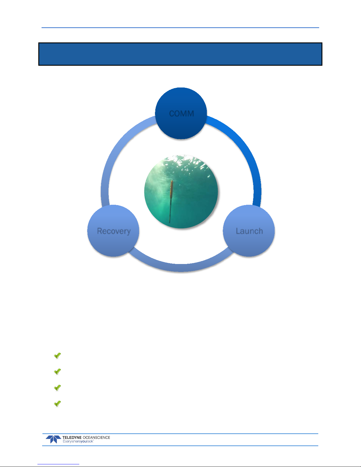
COMM
LaunchRecovery
Page 10

March 2018 rapidCAST User’s Guide
Page 4
EAR-Controlled Technology Subject to Restrictions Contained on the Cover Page.
Terminology
Use this section to learn the terms that will be used throughout the manual.
Figure 1. Winch Assembly Overview
Figure 2. Interface Module Overview
Page 11
rapidCAST User’s Guide March 2018
EAR-Controlled Technology Subject to Restrictions Contained on the Cover Page.
Page 5
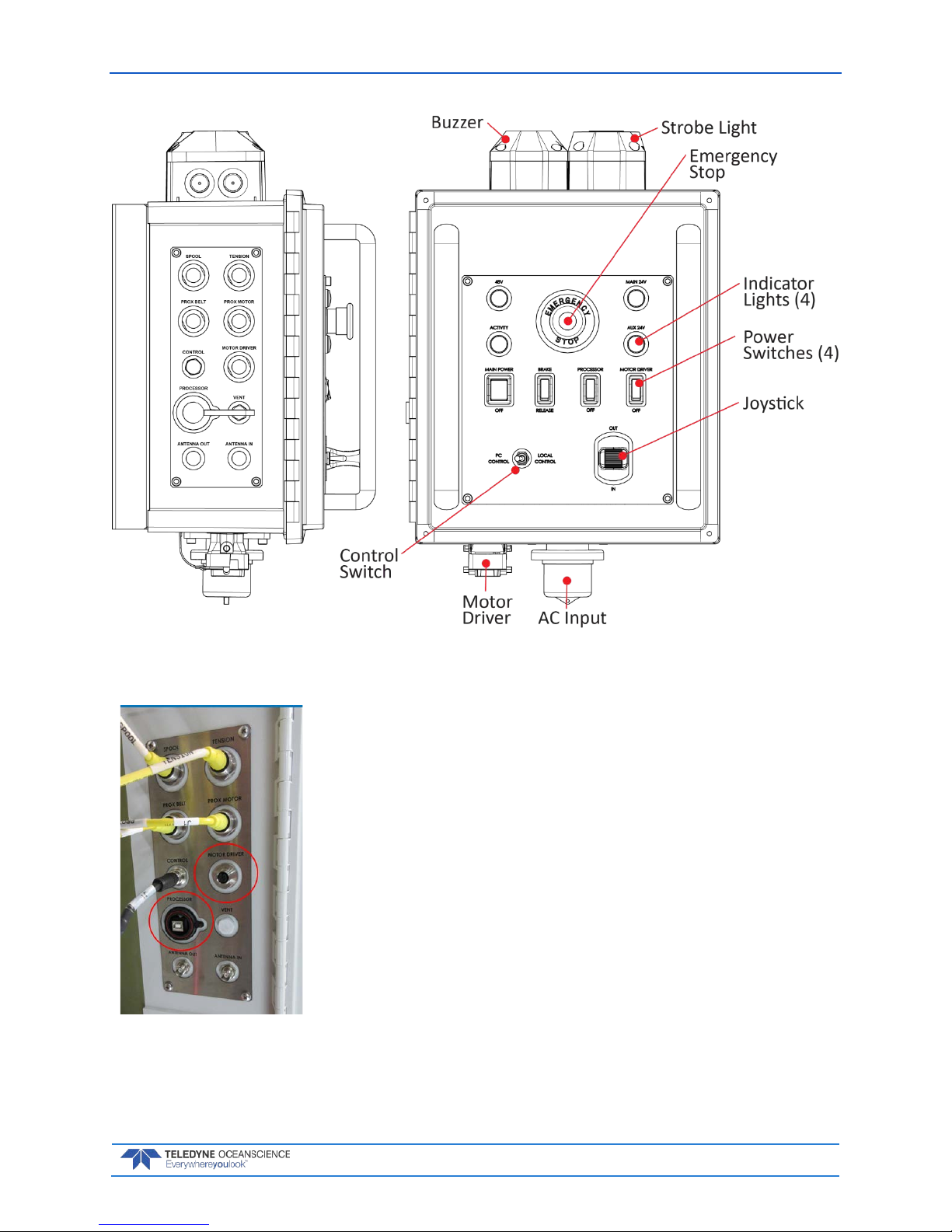
Figure 3. Control Module Overview
• The top four connectors are latching non-threaded push-pull
types.
• The Control and Antenna connectors are threaded and screw
on.
• Ensure that connectors are fully-seated; otherwise water re-
sistance may be compromised!
• Connectors circled in red are used only in special circum-
stances and are normally left disconnected. Make sure the
caps are on during a deployment to protect the connectors.
Page 12
March 2018 rapidCAST User’s Guide
Page 6
EAR-Controlled Technology Subject to Restrictions Contained on the Cover Page.
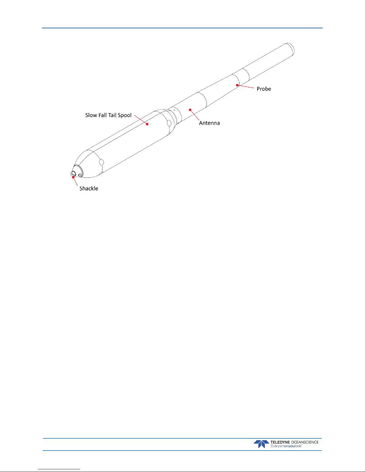
Figure 4. Probe Assembly Overview
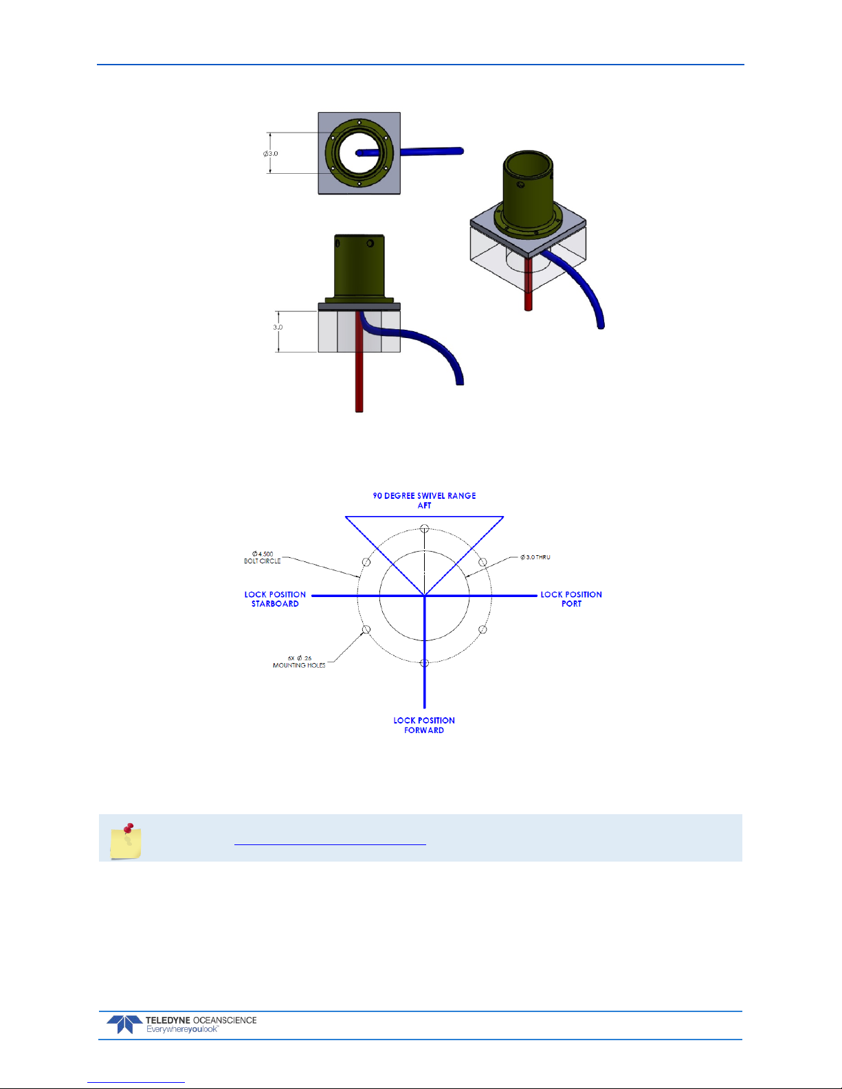
Mechanical Requirements
Mounting Requirem ents: The ideal deployment location is in the center of the vessel, with deployment directly over the aft rail, but other locations may be possible. The swivel base should be mounted
within 24 inches of the aft rail. Oceanscience can provide designs for mounting options if necessary. Installation of a serial cable running from the rapidCAST electronic control module to the survey PC is required. As the probe uses wireless Bluetooth telemetry, no cabling is required for data download.
The figure below depicts mounting and cable clearance requirements. Routing of the winch power and
data cables must be taken into consideration. The bolt circle should be oriented as shown below because
the swivel base has built in stops to control the rotation of the winch, see Figure 6. The mounting platform
should be able to withstand a moment of 70ft-lbs with little to no deflection. Below the mounting platform, a 3.0 inch clearance is required for cable routing. Straight down cable routing is shown in RED.
Sideways cable routing is also possible if there is a minimum 3.0 inch clearance, shown in BLUE.
Page 13
rapidCAST User’s Guide March 2018
EAR-Controlled Technology Subject to Restrictions Contained on the Cover Page.
Page 7
Figure 5. Cable Clearance Requirements
Figure 6. Mounting Requirements
See Appendix A - Installation Drawings for a detailed Pipe Mount Installation Drawing.
Page 14

March 2018 rapidCAST User’s Guide
Page 8
EAR-Controlled Technology Subject to Restrictions Contained on the Cover Page.
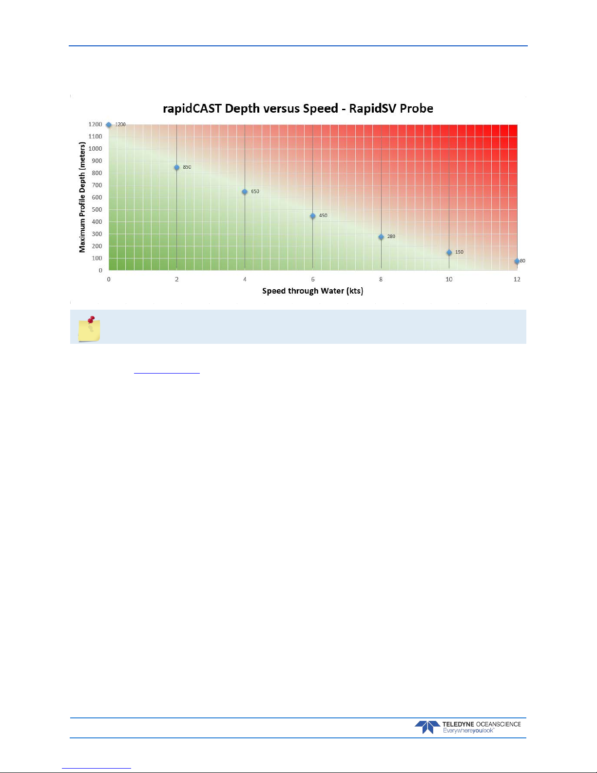
Profiling Depth: The nominal specification is 500m at 8kts, which requires ~1500m of line. As the vessel speed decreases, the achievable cast depth increases up to the maximum pressure rating of the probe
for long stationary casts. As very deep casts are much longer in duration, the vessel cannot be moving appreciably as this will waste available line to account for the movement of the ship. As the vessel speed increases above 8kts, the achievable depth decreases to maintain the profiler in a safe condition during recovery (low line tension). The maximum vessel speed under normal operation is 12kts. The motor rpm
and braking time may be adjusted by the user to suit the survey conditions.
As long as the vessel retains a nominal forward motion to prevent entangling of the line in the ship propeller. The maximum profile depth is then limited by the amount of line on the rapidCAST spool and the
probe pressure rating of 2000m.
Line Type: Hollow Spectra line of 500lb breaking strength with an 800lb leader.
Line Length: The maximum amount of line that can be loaded is about 3000m. Typically, 1500m is
used. Line length does not directly correlate to maximum cast depth underway. This depends on ship
speed because the total line paid out is a product of ship movement and probe depth.
Electrical Requirements
Input Voltage: 90 — 264 VAC RMS, Single Phase
Input Frequency 47 — 63 Hz
Max Current (at 115 VAC Input): 16 A
Max Current (at 230 VAC Input): 10 A
Inrush Current (Cold Start): 50 A Typical
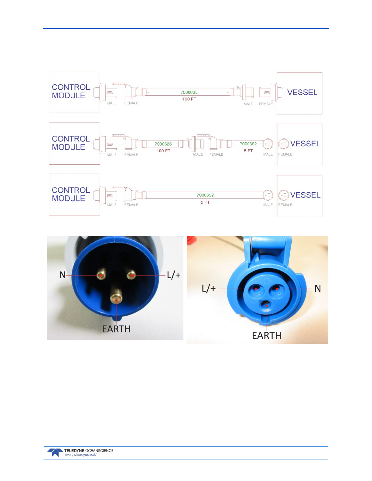
Power Connectors
The rapidCAST system ships with 2 power cables, offering flexibility in the connectors used for power.
• Part Number 7000625 - 100-ft Power Cabl e Ter m inated with IEC 60309 250V 16A, 6H, Blue
P+N+E Plug, that mates to IEC 60309 250V 16A, 6H, Blue P+N+E Socket
• Part Number 7000652 - 5-ft Cable Adapter Terminated with NEMA 5-15P Plug, that mates to
NEMA 5-15R Receptacle
Page 15
rapidCAST User’s Guide March 2018
EAR-Controlled Technology Subject to Restrictions Contained on the Cover Page.
Page 9
Power Cable Connections
The diagram below shows how the power cables may be connected.
Figure 7. Power Cable Connections
Figure 8. 7000625 Cable Plug/Termina-
tion
Figure 9. 60309 Vessel Socket / Recepta-
cle/ Outlet
Page 16
March 2018 rapidCAST User’s Guide
Page 10
EAR-Controlled Technology Subject to Restrictions Contained on the Cover Page.
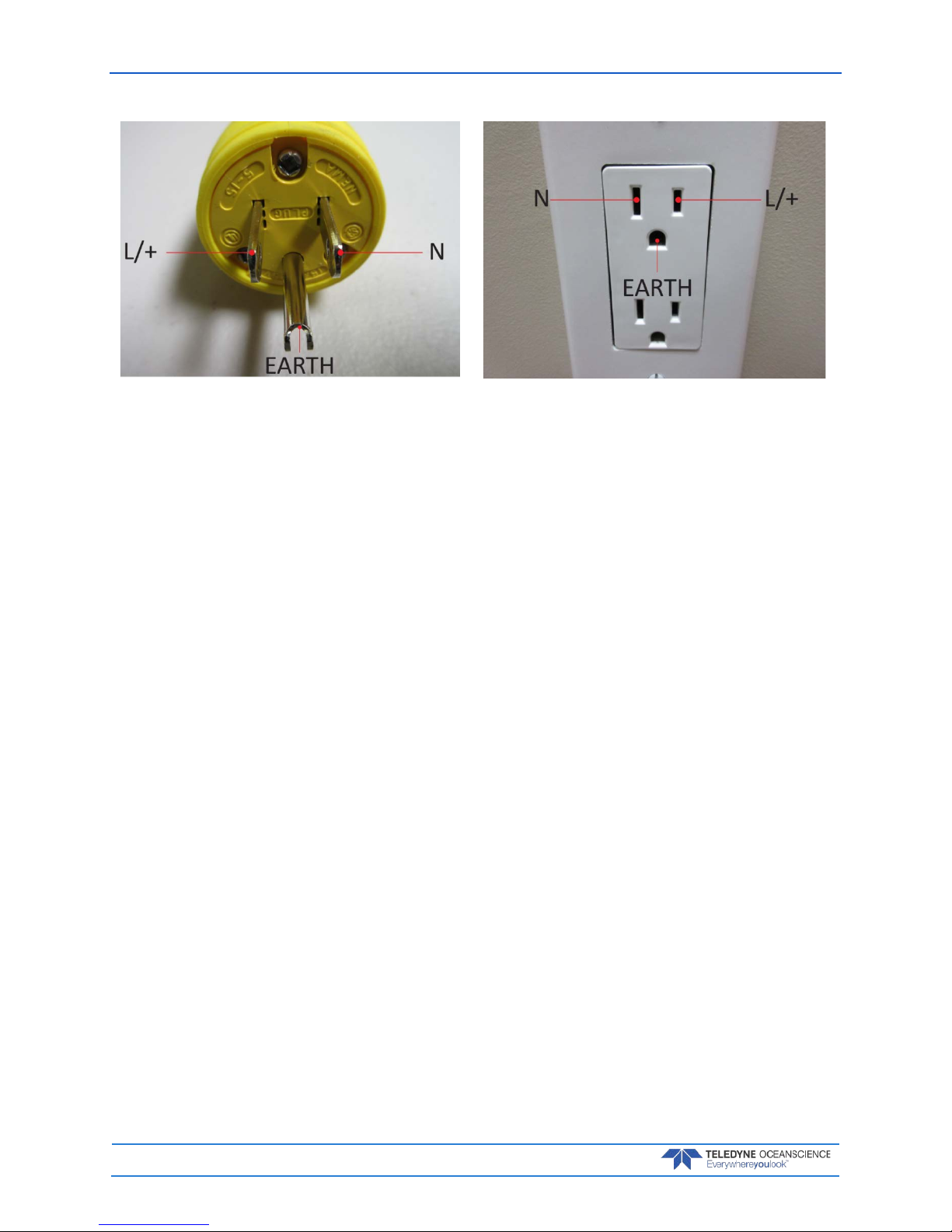
Figure 10. 7000652 Cable Plug/Termination Figure 11. Vessel Socket/Receptacle/Outlet
Page 17

rapidCAST User’s Guide March 2018
EAR-Controlled Technology Subject to Restrictions Contained on the Cover Page.
Page 11
Performance Specifications and Operational
Limits
Winch Length 48cm (18.89”)
Length with Davit 200cm (78.74”)
Width 71cm (27.95”)
Height 46cm (18.11”)
Weight 36kg (79.36 lbs.)
Input Voltage 48 VDC/ 2.0 kW
Line Capacity 3000m
Construction Aluminum/Delrin/Titanium/Stainless Steel
Probe Recovery Speed 0.5-2m/s (1.5-6.6 fps)
Mount Swivel base (12cm diameter)
Hardware Stainless Steel
Control Module Weight 14kg (30.86 lbs.)
Length 52cm (20.47”)
Width 34cm (13.34”)
Height 29cm (11.42”)
Input Power 90-264 VAC (47-63 Hz)
Output Power 48 VDC
Davit Length 160cm (63”)
Diameter 5cm (2”)
Weight 1.18kg (2.6 lbs.)
Valeport rapidSV Probe Length (with tail spool) 111cm (43.70”)
Diameter 5cm (1.96”)
Weight (in air) (without tail spool) 4.48kg (9.87 lbs.)
Internal Memory 1000 casts
Depth Rating 2000m
Pressure Resolution ±0.001% range
Accuracy ±0.05% range
Range 0-200 dBar
Temperature (if fitted) Resolution 0.001C
Accuracy ±0.01C
Range -5 to 35C
Sound Velocity Resolution 0.001m/s
Accuracy ±0.02m/s
Range 1375 - 1900m/s
Profiling Capability >500 m at 5 kts or deeper at slow speeds
(see Table 1, page 12)
Page 18
March 2018 rapidCAST User’s Guide
Page 12
EAR-Controlled Technology Subject to Restrictions Contained on the Cover Page.
Table 1. rapidCAST Depth versus Speed
The table above applies to the RapidSV probe. Call for details on other probes.
Each standard spool is delivered with 1954 meters of line, of which 1700 meters can be used for normal
operation (see Line Properties, page 30). Typically, only 1200 meters of line are used.
Deployments less than 100 meters deep:
• The buoyancy tailspool can be used. In this configuration, the probe will fall at approximately
3 m/sec.
The following general specification applies:
• Boat speed relative
Deployment greater than 100 meters deep:
• The buoyancy tailspool CANOT be used. In this configuration use the plain tailspool, the probe
will fall at approximately 4 m/sec.
Page 19
rapidCAST User’s Guide March 2018
EAR-Controlled Technology Subject to Restrictions Contained on the Cover Page.
Page 13
Quick Review
Check that you know the
Terminology used.
Reference Figure 1 through
Figure 4.
Check that the boat meets
the Mechanical and
Electrical Requirements
Reference page 6 to 8.
Page 20

March 2018 rapidCAST User’s Guide
Page 14
EAR-Controlled Technology Subject to Restrictions Contained on the Cover Page.
Installation
I NSTALLATION INCLUDES THE FOLLOWING STEPS:
Unpacking the rapidCAST system
Installing the RapidCAST Control Software
Learning Cable Connections and Switch Functions
Mounting the Winch
Verifying Probe Communications
COMM
LaunchRecovery
Page 21
rapidCAST User’s Guide March 2018
EAR-Controlled Technology Subject to Restrictions Contained on the Cover Page.
Page 15
Unpacking the rapidCAST system
Included with the rapidCAST:
Table 2. Inventory
Packed in
transit case:
Part Number Description Quantity
6001752:
CASE,
TRANSIT,
RCAST,
WINCH
6001417 ASSY, WINCH, RAPIDCAST 1 ea
7000625 CABLE, AC POWER, RCAST, 30.5M 1 ea
7000652 CABLE, AC POWER, RCAST, 1.5M 1 ea
75JK6001-00 Documentation kit contains the RapidCAST Interface software program, USB RS-485
Driver, manuals, and backup driver software.
1 ea
9002211 CABLE, RF, TNC STRAIGHT PLUG, LMR400, 40M 1 ea
9002104:
CASE,
TRANSIT,
RCAST, DAVIT
71J-5001-00 ASSY, DAVIT, RCAST, W/PULLEY 1 ea
9002209 SHOULDER STRAP, DAVIT CASE, RCAST 1 ea
6001754:
CASE,
TRANSIT,
RCAST,
CONTROL
MODULE
6001427 ASSY, CONTROL MODULE, RAPIDCAST 1 ea
6001432 ASSY, INTERFACE MODULE, RAPIDCAST 1 ea
8000592 MOUNT, PIPE FLANGE, RCAST 1 ea
6001436 ASSY, PROBE BRACKET, RCAST 2 ea
6001751 KIT, TOOLS AND SPARES, RCAST 1 ea
7000650 CABLE, TELEMETRY AND CONTROL, RCAST 1 ea
6000617 SET, TAILSPOOL W/BULKHEAD, RCAST/UCTD 1 ea
6000630 SET, TAILSPOOL W/BULKHEAD, RCAST/UCTD, W/BUOYANCY MODULE 1 ea
8000112 TRAINING PROBE, RCAST/UCTD 1 ea
9002212 CABLE, RF, TNC STRAIGHT PLUG, LMR400, 5M 1 ea
9002173 ANTENNA, 2.4 GHz 8dBi FLAT PATCH W/ TNC CONNECTOR 1 ea
Safety
Important Safety Warnings
Do not put your hands inside the frame unless the system is Locked Out.
Always assume the system is live.
When in doubt use Emergency Stop.
Stand clear of line, do not stand in loops or wrap line around your hand.
Page 22
March 2018 rapidCAST User’s Guide
Page 16
EAR-Controlled Technology Subject to Restrictions Contained on the Cover Page.
Important Deployment Warnings
Never go past the maximum line payout.
Line is taped on the spool. Never get in to the bottom RED layer or you will lose a probe.
If the winch cannot pull the line in or the brake is not working, STOP the vessel immediately.
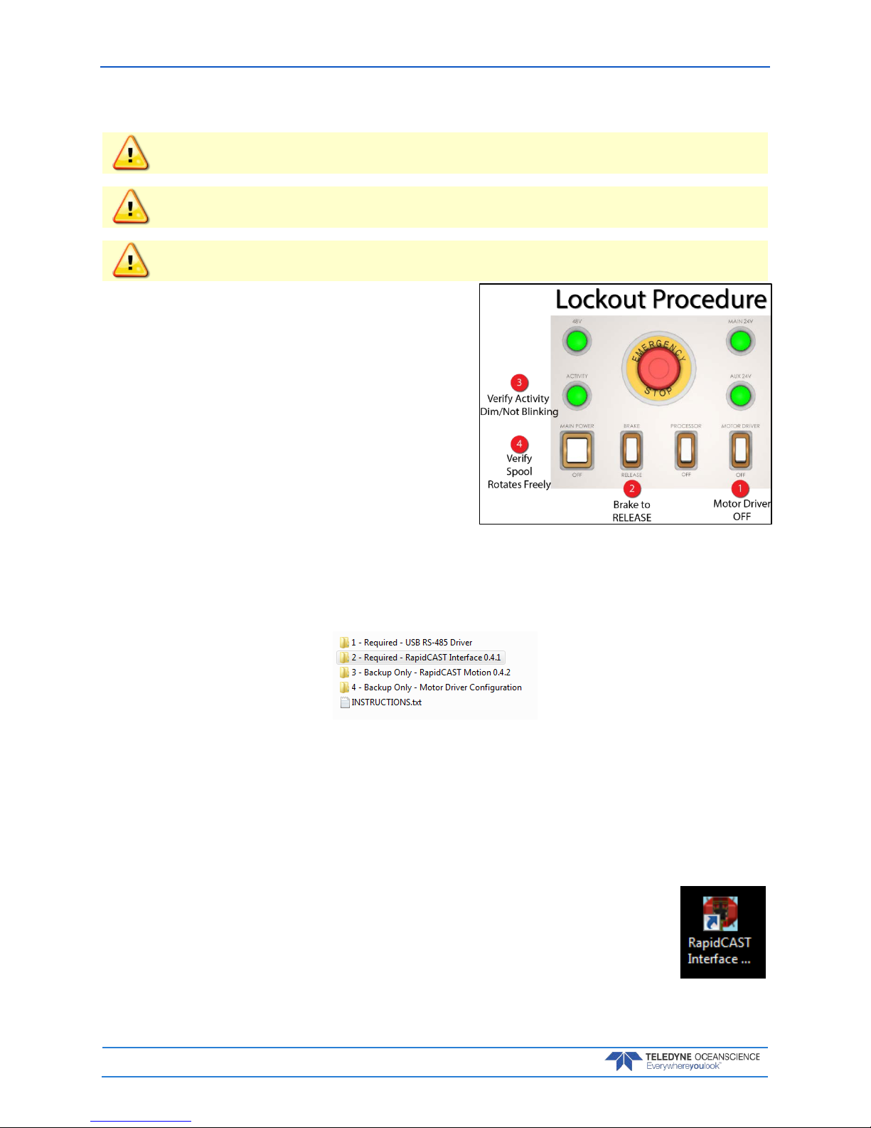
Lockout Procedure
To lock out the system:
1. Switch Motor Driver OFF.
2. Switch Brake to RELEASE.
3. Check to ensure Activity Light is Dim/Not blinking.
4. Check to see if the spool rotates freely.
The system is now SAFE.
Installing the rapidCAST Interface Software
The rapidCAST Control Software is located on the documentation CD.
To install the drivers and software:
1. Connect the system and apply power. Connect the PC to the Control U S B por t of Ra pid CA S T Interface Module, which should automatically install two USB Serial Port devices on the PC.
Make note of the serial port numbers because they will be used for:
Lower Comm port for Telemetry
Higher Comm port for Control
2. Install the USB RS-485 Driver located in the 1 – Required – USB RS-485 Driver folder of the documentation CD, specifically the RS-422/485 USB Adapter.
3. Install the RapidCAST Interface software by double-clicking on the RapidCAST
Interface X.xx.exe file (where X.xx is the version number) located in the 2 – Required – RapidCAST Interface X.xx folder. Administrator access is required to
properly install the software. A desktop icon is added: Double-click to run the
software.
Page 23

rapidCAST User’s Guide March 2018
EAR-Controlled Technology Subject to Restrictions Contained on the Cover Page.
Page 17
Software Architecture
RapidCAST encompasses 2 types of software: RapidCAST Motion and RapidCAST Interface.
• RapidCAST Motion is firmware that resides inside the Control Module, responsible for real-time
motion control and winch operation. It exposes a text-based interface that allows the winch to be
controlled via string messages. Due to the large number of messages required, however, users do
not interact directly with RapidCAST Motion. When new functionality is introduced through future software releases, RapidCAST Motion can be upgraded in the field (see Updating the Winch
Software).
• RapidCAST Interface is a graphical user interface that runs on a PC and is the primary method for
operating the winch. It functions as a messaging and task management layer that transmits commands to RapidCAST Motion, hiding the latter’s complexity behind a friendly and intuitive graphical interface.
As needs arise, Teledyne Oceanscience may modify or upgrade either software independently of the other.
Because of their message-based infrastructure, RapidCAST Motion and RapidCAST Interface must have
the same Compatibility Group to ensure proper function. A Compatibility Group is simply a number that
identifies whether a particular version of RapidCAST Motion or RapidCAST Interface are “speaking the
same language” and are therefore fully compatible.
The About window (see Using the GUI Windows and Controls) identifies the software versions on the
Control Module and on the PC, as well as their respective Compatibility Groups. If there is a mismatch,
the About menu item will be red. If there is a compatibility mismatch, the system should not be
operated, and the software needs to be upgraded or downgraded until their Compatibility
Groups match.
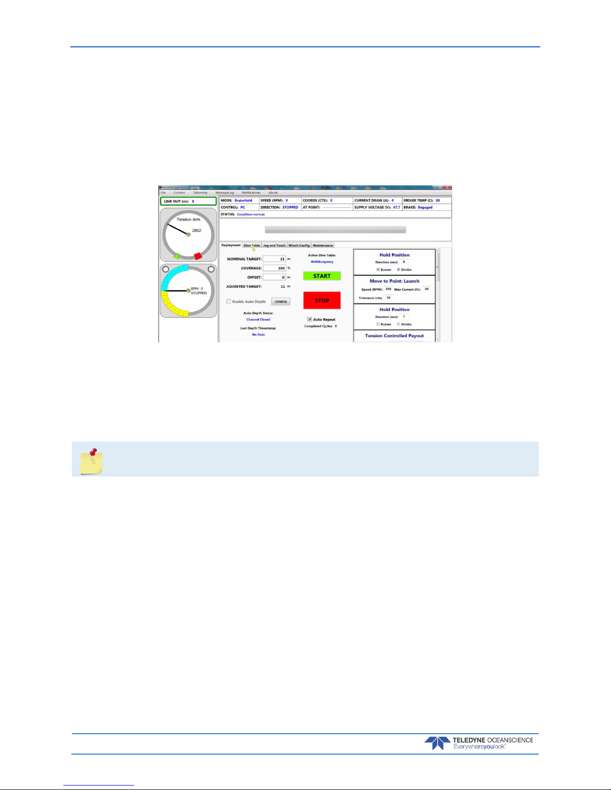
A Tour of the RapidCAST Interface
The Dashboard is the top panel and gives the operator a snapshot of the winch’s health and current state.
Important information such as the spool’s speed and rotation direction, the power-supply voltage, and
brake status are reported here. The Dashboard keeps the user informed of the system’s critical operating
parameters.
The Task Bar is the second section. It reports the winch’s current assigned task and provides a progress
estimate.
The bottom panel is the Tab Group, which is a collection of tabbed windows grouped according to common functionality. The Tabs are organized as follows:
• Deployment: Allows the user to set deployment depth, as well as monitor and control an auto-
mated deployment.
• Dive Table: Identifies the dive table used to calculate the Tension-Controlled Payout duration
from a target depth. Allows the user to define the polynomial coefficients of additional dive tables
and switch between them.
• Jog and Teach: Allows the user to jog (move) the winch as well as define positions.
• Winch Config: Allows the user to modify advanced operating parameters.
• Maintenance: Contains a grouping of varied tasks associated with system maintenance and atypi-
cal activities such as software updates and health logging.
A Gauge Cluster on the left provides a graphical representation of the Tension Arm position as well as the
spool’s speed and rotation direction. When the Tension Arm is at its lowest position, the angular gauge in
the Interface Software should show the Tension Arm pointing at the far edge of the red zone. If the Tension Arm is not depicted at this position when the arm is fully relaxed, calibration is needed (see Tension
Arm Calibration).
Page 24
March 2018 rapidCAST User’s Guide
Page 18
EAR-Controlled Technology Subject to Restrictions Contained on the Cover Page.
The spool indicator shows the speed of the line out (blue) and line in speed (yellow). The two white circles
represent the LevelWind position, and blink when the LevelWind is at the full left/right positions.
Line Out - Calculating the length of line paid out depends on how tightly the spool is packed, as well as
the amount of line loaded on the spool (both of which affect the spool’s effective circumference – an important variable when calculating line length). The spool’s circumference decreases as more line is paid
out, and though this behavior has been mathematically modelled as part of the line-length calculation, the
values given by the Line Out display should still be treated as an approximation. Line length is measured
relative to the encoder zero position (“home”). It may be negative if the winch has rotated inward relative
to zero.
Driver Temp: Displays the temperature of the motor controller. This value will increase or decrease depending on the load applied to the motor. Note: Motor will shut down at 70C.
Supply voltage: Indicates the state of the 48V supply, which powers the Spool Motor.
Cable Connections
The system is shipped with the winch end of the cables pre-connected for ease of installation.
The following is for reference.
To remove the covers (only necessary if cables are not connected on the winch end):
1. Remove the covers on the winch assembly.
2. First, remove the four (4) screws and flat washers on the top cover. Slide the top cover toward the
rear of the winch to remove it.
3. Remove the fours screws and flat washers on each side cover and slide the cover down, and then
pull the bottom handle to release the bottom bracket.
4. Next, slide the cover up and pull out slightly to remove it.
Page 25
rapidCAST User’s Guide March 2018
EAR-Controlled Technology Subject to Restrictions Contained on the Cover Page.
Page 19
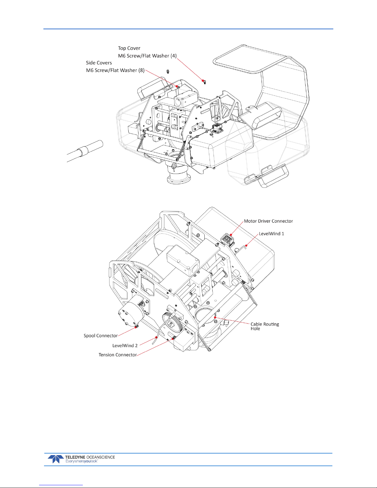
Figure 12. Removing the Winch Assembly Covers
Figure 13. Winch Assembly Connectors
To Connect the Cables:
1. Route all five (5) cables through the cable routing hole. Ensure that the cables do not interfere
with the motion of the spool, LevelWind, or tension arm.
2. Connect the Motor Driver cable between the Control Module and Winch. The Motor Driver connector is located under the motor side cover on top of the motor.
3. Connect the Spool cable between the Control Module and Winch. The Spool connector is located
under the belt side cover.
Page 26
March 2018 rapidCAST User’s Guide
Page 20
EAR-Controlled Technology Subject to Restrictions Contained on the Cover Page.
4. Connect the Tension cable between the Control Module and Winch. The Tension connector is located under the belt side cover.
5. Connect the LevelWind PROX sensor cables between the Control Module and Winch. The LevelWind1 connector is located under the motor side cover; the LevelWind2 connector is located under the belt side cover.
6. Use Figure 12 to re-install the winch assembly covers.
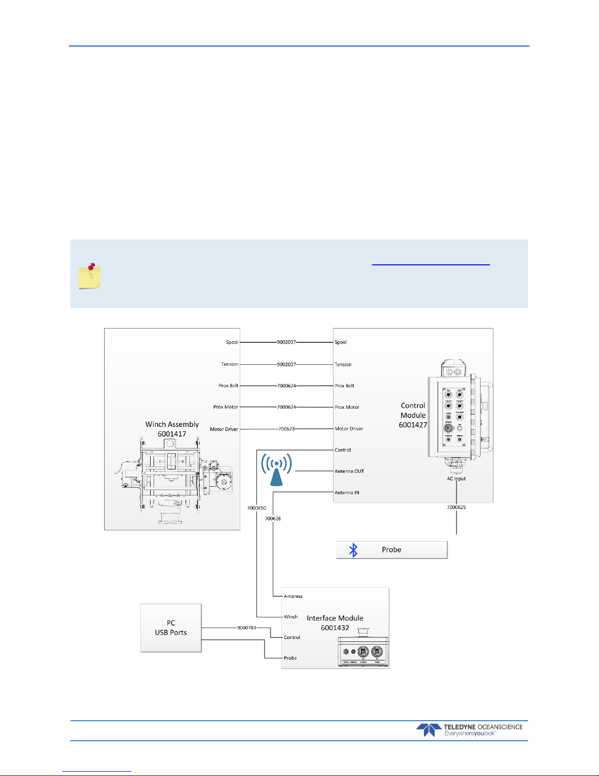
7. Connect the Control cable between the Control Module and Interface Module.
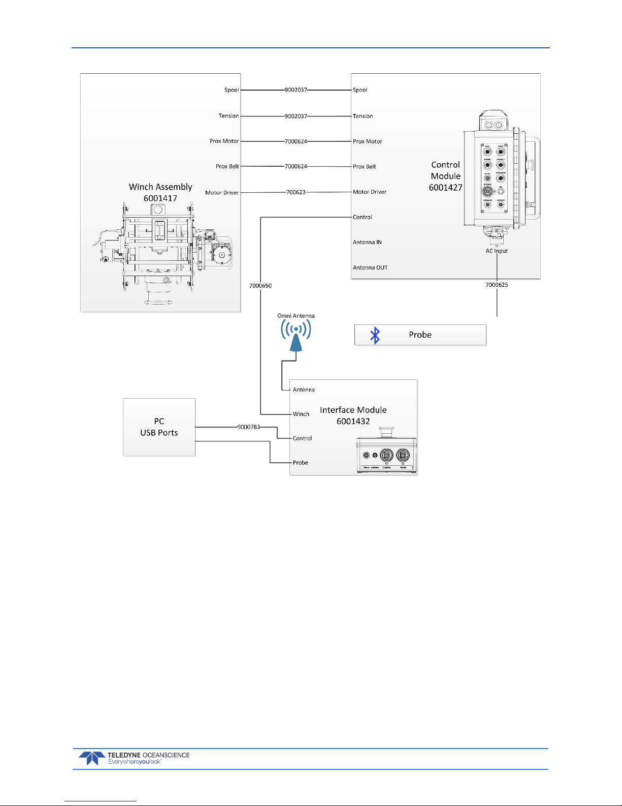
8. Connect the Antenna cable between the Control Module and Interface Module. Connect the Patch
antenna to the Control Module (larger vessels use Figure 14). Alternately, you can connect the
Omni antenna directly to the Interface Module and omit using the 9002211 cable (smaller vessels
use Figure 15).
9. Connect the AC power cable to the Control Module.
Do not connect the 9000783 USB cable to PC computer until the rapidCAST Interface
software is installed and the system is powered up. See Connecting the Winch to a PC for
details.
The Processor connector on the Control Module is not used for normal operation. Keep the
dust cap installed.
Figure 14. rapidCAST Cable Connections (Large Vessels)
Page 27
rapidCAST User’s Guide March 2018
EAR-Controlled Technology Subject to Restrictions Contained on the Cover Page.
Page 21
Figure 15. rapidCAST Cable Connections (Small Vessels)
Page 28
March 2018 rapidCAST User’s Guide
Page 22
EAR-Controlled Technology Subject to Restrictions Contained on the Cover Page.
Antenna Position
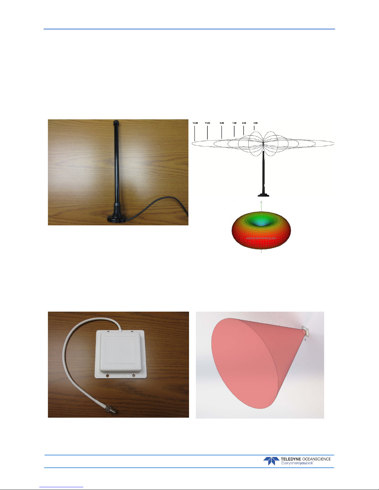
The rapidCAST system includes two types of antenna. The size of the vessel will determine which antenna
to use.
Omni Antenna – Use this antenna when the distance between the Interface Module and Control Module is less than 10 meters. See Figure 15 for cable connections.
The antenna is Omni directional (the best reception is around the antenna in a doughnut shape; do not
orientate the antenna by pointing the tip of the antenna at the probe).
Figure 16. Omni Antenna
Patch Antenna – Use this antenna when the distance between the Interface Module and Control Module is over 10 meters. See Figure 14 for cable connections.
Orientate the antenna as shown in Figure 17. The best reception is when the probe is in the center of the
approximately 30 degree cone.
Figure 17. Patch Antenna
Page 29

rapidCAST User’s Guide March 2018
EAR-Controlled Technology Subject to Restrictions Contained on the Cover Page.
Page 23
Switch Functions
Emergency Stop – Removes all power except the 24 VDC Auxiliary power to maintain lights. There are
two emergency stop buttons; one on the Control Module and one on the Interface Module. If the emergency stop button is pushed in, turn and pull out to restore power. The rapidCAST system will reboot in a
few seconds.
Main Power – Turn switch off to remove all power to the system.
Brake – Removes the 24 VDC power to the winch break motor. Processor – Removes the 24 VDC to the
Control Module processor.
Motor Driver – Removes the 48 VDC to the motor controllers.
Control Switch – The switch changes control between the PC running the rapidCAST Interface Software
(PC Control position) and the joystick (Local Control position). When the switch is in:
• PC Control position, the Activity light will flash two rapid blinks and then 1 second off
• Local Control position the Activity light will flash three rapid blinks and then 1 second off.
Joystick – If the toggle switch is in the Local Control position, use the joystick to manually operate the
winch. OUT will deploy cable; IN will retract cable. The winch is limited to 100 RPM maximum while using the joystick.
When the joystick is not actively being used, the toggle switch should be set to PC Control to
properly engage the brake.
Figure 18. Control Module Figure 19. Interface Module
The control panel is equipped with a joystick that allows the spool to be controlled directly by
an operator on deck. Local control is convenient when the user needs to operate the spool
without having to coordinate with a person running the PC. The joystick is typically used
when retrieving the probe out of the water and bringing it on deck, or when putting the
probe back into the water. The joystick is sensitive and should be operated slowly!
Page 30

March 2018 rapidCAST User’s Guide
Page 24
EAR-Controlled Technology Subject to Restrictions Contained on the Cover Page.
LED Functions
LEDs on the Control Module provide a snapshot of power supply health and system status. During normal operation, all LEDs should be lit. These LEDs consist of:
48V LED (GREEN): Indicates the state of the 48V supply which powers the Spool Motor.
ON: The power supply is functioning.
OFF: The power supply is inactive. This may be due to a lack of input AC power, a power supply mal-
function, the Main Power Switch being in the OFF position, the Control Cable being disconnected, or
Emergency Stop being pressed.
MAIN 24V (GREEN): Indicates the state of the 24V supply which powers the Motor Brake.
ON: The power supply is functioning.
OFF: The power supply is inactive. This may be due to a lack of input AC power, a power supply mal-
function, the Main Power Switch being in the OFF position, the Control Cable being disconnected, or
Emergency Stop being pressed.
AUX 24V (GREEN): Indicates the state of the 24V supply which powers the Processor, the Tension Arm
and Spool Encoders, the LevelWind Proximity Sensors, and other low-power digital electronics.
ON: The power supply is functioning.
OFF: The power supply is inactive. This may be due to a lack of input AC power, a power supply mal-
function, or the Main Power Switch being in the OFF position.
Unlike other LEDs, this LED should remain ON even when Emergency Stop is pressed or the
Control Cable is disconnected.
ACTIVITY LED (GREEN): Indicates the state of the Motor Driver.
Slow Blink (1 Sec. On + 1 Sec. Off): The Motor Driver is powered but is not yet ready for normal
operation. If the Motor Brake is released in this state, the Motor will add passive regenerative resistance to the rotation of the spool. The degree of resistance is proportional to the speed of rotation,
i.e., attempts by hand to move the spool faster will result in stiffer resistance.
Single Fast Blink (0.5 Sec. On + 1.5 Sec. Off): The Motor Driver is ready for normal operation,
and the winch is currently under PC control.
Three Fast Blinks (3X 0.5 Sec. On + 0.5 Sec. Off): The Motor Driver is ready for normal operation, and the winch is currently under Local (Joystick) control.
OFF: The Motor Driver is not receiving power and is therefore inactive. This may be due to a lack of
input AC power, the Main Power Switch being in the OFF position, the Control Cable being disconnected, or Emergency Stop being pressed. If the Motor Brake is released while the Motor Driver is unpowered, the spool can be rotated easily with minimal resistance (regenerative braking is disabled).
EMERGENCY STOP LED (RED): Allows the Emergency Stop to be located in dark environments and
indicates its state.
ON: The Emergency Stop has not been pressed, and the system is ready for normal operation.
OFF: The Control Module Emergency Stop and/or Interface Module Emergency Stop may have been
pressed, the Control Cable may be disconnected, the Main Power Switch may be in the OFF position,
or the Control Module is not receiving input AC power.
Page 31

rapidCAST User’s Guide March 2018
EAR-Controlled Technology Subject to Restrictions Contained on the Cover Page.
Page 25
Installing the rapidCAST System
Environmental Conditions
The RapidCAST is rated to IP65. All exterior components are sealed and water-tight when the cables are
mated. Dust caps should be installed on connectors when they are not in use.
Overall, the system has very good UV resistance, but should not be left outdoors for extended periods of
time, i.e. months.
When installed in cold/wet environments near freezing (0°C), ice may form on the system. Due to the
mechanical nature of the system, it is necessary to prevent and de-ice the system prior to and during operation. Store the system inside or cover it when not in use to prevent icing.
Hot environments (greater than 30°C) require careful consideration of the environmental conditions. The
radiative heat from the sun and ship deck can cause ambient shipboard temperatures to exceed 40°C.
When operating in a hot environment the following items should be considered:
1. Deep casts at higher ship speeds will generate the most heat because the motor is working hard
for an extended period of time.
2. Shallow casts at lower ship speeds will generate the least amount of heat.
3. Consider reducing the duty cycle of the system and allow it to cool off between casts if heat gener-
ation is excessive.
4. Remove the orange side cover on the motor side during operation to assist with cooling.
The RapidCAST system monitors the temperature of the Motor Controller which has a maximum allowed
temperature of 70°C. If the Motor Controller temperature reaches 70°C, the brake will engage and the
motor will no longer be powered. The Motor Controller will re-activate when the temperature drops below 70°C. If this condition occurs, the user should re-evaluate the duty cycle.
Page 32

March 2018 rapidCAST User’s Guide
Page 26
EAR-Controlled Technology Subject to Restrictions Contained on the Cover Page.
Lifting the RapidCAST System
DO NOT USE THE TENSION ARM AS A LIFT POINT. The tension arm is not load bearing and
could be damaged if it is used as a lifting point.
The system should be lifted by any of the four (4) handles available on the covers. If the covers are removed, the system can be lifted by the frame.
The top handles can accommodate lifting slings if a crane is available for loading. The center of mass is
located approximately where shown in the figure below.
Figure 20. Center of Mass (CM) Location
Page 33

rapidCAST User’s Guide March 2018
EAR-Controlled Technology Subject to Restrictions Contained on the Cover Page.
Page 27
Installing the Pipe Mount
A custom mounting plate is required to mount the Pipe Mount, PN 8000592.
An adapter is available from Oceanscience that will facilitate the installation of a RapidCAST where an
Underway CTD was previously installed. One such adapter is shown below.
Attach the pipe mount to the custom mounting plate using 6 X M6 or 6 X ¼-20 screws as shown below:
Figure 21. Attaching Pipe Mount Figure 22. Pipe Mount Installed on UCTD Adapter
Plate
Page 34

March 2018 rapidCAST User’s Guide
Page 28
EAR-Controlled Technology Subject to Restrictions Contained on the Cover Page.
Installing the Winch on the Pipe Mount
1. Pipe Mount
2. Disengage the winch spring pin by pulling and then rotating. Slide the winch on to the pipe mount
and rotate the winch back and forth until it is fully seated on the pipe mount.
3. Install the davit and retaining pin. Block is oriented downward as shown in Figure 23.
4. Engage the spring pin by rotating until it engages in the slot.
Figure 23. Installing the Winch on the Pipe Mount
Optional mounting shown using a custom pedestal rather than the ship’s rail.
Page 35

rapidCAST User’s Guide March 2018
EAR-Controlled Technology Subject to Restrictions Contained on the Cover Page.
Page 29
Installing the Control Module
The control module has two standard 1-5/8 inch strut channels located on the back. These will accept
standard pipe mounts (not included). The control module is mounted within 8 feet of the winch and to the
ship’s rail or other available mounting location
Figure 24. Mounting the Control Module
Figure 25. Control Module Dimensions
Page 36

March 2018 rapidCAST User’s Guide
Page 30
EAR-Controlled Technology Subject to Restrictions Contained on the Cover Page.
Line Properties
Spectra Line is composed of braided High-Molecular-Weight-Polyethylene.
• Negligible stretching means line does not snap back violently if severed under load.
• Rated tensile strength of 226 kg.
• Can splice multiple segments together.
• Spectra Line is very sensitive to heat, especially heat caused by friction. Portions of line that
have been exposed to high heat should not be used, as heat permanently damages the line and
makes it prone to breaking.
Never wrap line around fingers or limbs while the winch is powered, as the line’s high tensile
strength can cause serious injury if body parts get caught by line as the winch is moving.
The very bottom layer of line is attached to the spool via adhesive tape and is not fixed in a
permanent way. This is intentional. If the probe is snagged by a submerged obstacle, the idea
is to allow the probe to be pulled cleanly off the spool once line runs out, rather than allow
the winch to be damaged by a permanently tethered probe.
Mission-critical cruises would typically carry backup line and probes. Backup winches,
however, are less likely to be carried, so the probe was considered the more expendable
element in this worst-case scenario.
Each spool is loaded with a grand total of ~1954 meters of line, of which ~1700 meters can be
used for normal operation. The line is spliced in three main sections:
• 55 m of “Leader” Red Line: When reeling in the probe, this warns users that the
probe is near the vessel.
• 1645 m of White Line: Normal line used for deployment.
• 254 m of “Terminal” Red Line: Bottom part of the spool. The RapidCAST winch
software prevents this portion from being paid out, and in fact, automatically stops
deployment before this portion of line is reached. If, for some reason, the winch
ends up using this segment of line (perhaps through misconfiguration, improper
homing, or this safeguard is overridden). If line is still being deployed and you start
to see red line, use the EMERGENCY STOP BUTTON.
Page 37
rapidCAST User’s Guide March 2018
EAR-Controlled Technology Subject to Restrictions Contained on the Cover Page.
Page 31
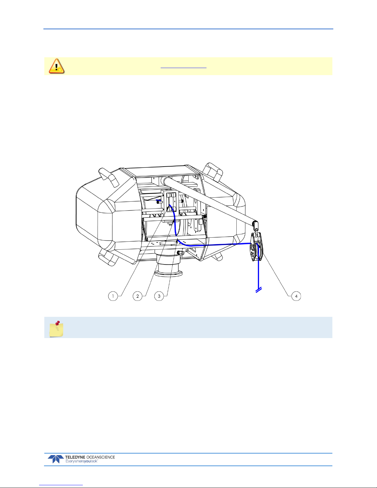
Line Routing Procedure
IMPORTANT!!! Follow the lockout procedure before routing the line.
Before routing the line, remove the short section of Duct Tape (PN 9002203) that is securing the line to
the spool. The spools are shipped with the line secured to the spool. Removal of the middle cover may be
necessary.
Line routing procedure:
1. Thru LevelWind rollers.
2. Over tension arm rotational axis roller.
3. Under tension arm outer roller.
4. Under the two horizontal pins in block and thru.
Figure 26. Line Routing Procedure
For shipping and storage, secure the line to the spool using a short 15cm piece of the
included Duct Tape (PN 9002203)
Page 38
March 2018 rapidCAST User’s Guide
Page 32
EAR-Controlled Technology Subject to Restrictions Contained on the Cover Page.
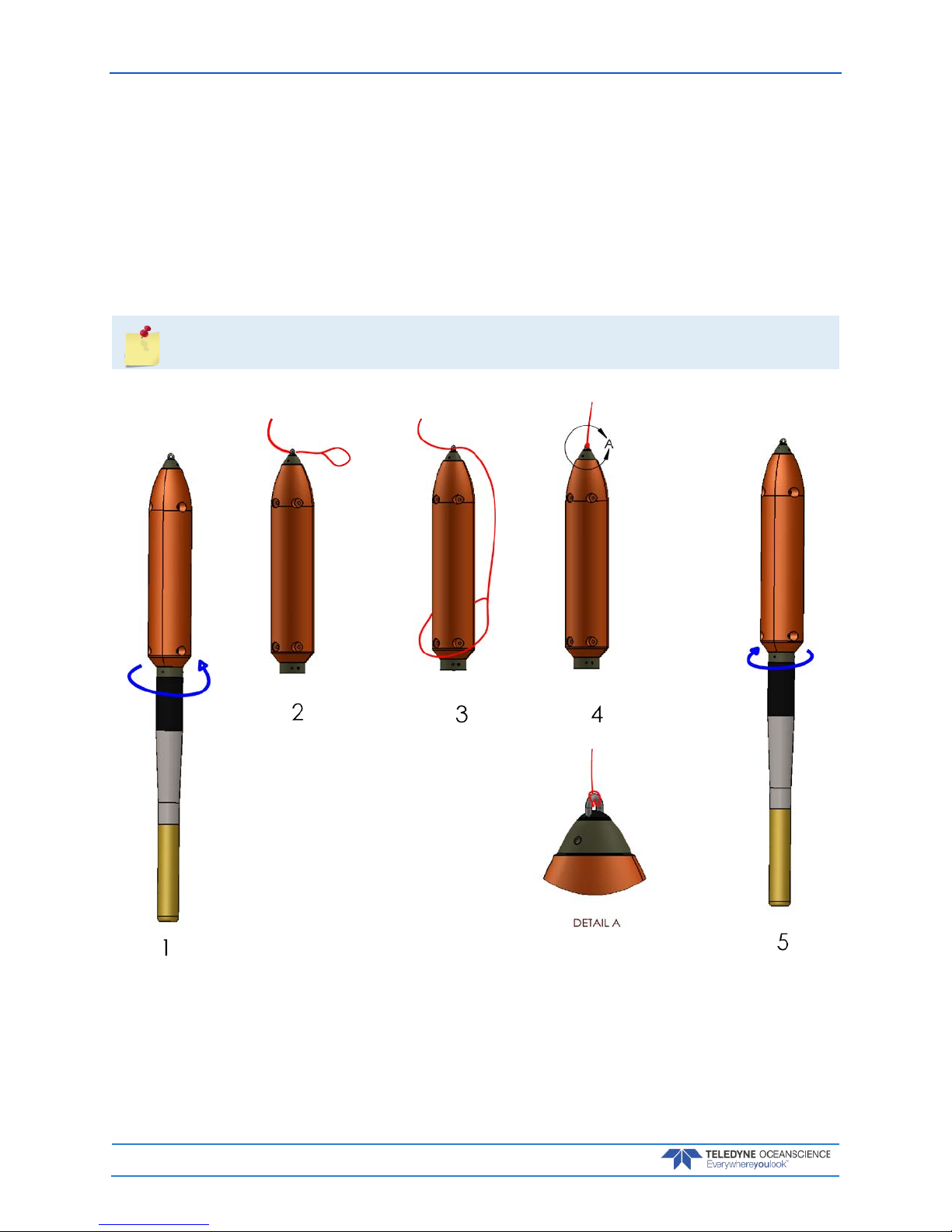
Installing and Connecting the Probe
1. Remove tailspool - depress white button and rotate tailspool as shown while holding probe.
2. Pass end of winch line thru shackle on tailspool.
3. Slide tailspool thru eye of winch line.
4. Pull winch line tight at shackle as shown. Make sure the eye of the line is not twisted and the eye
lines are evenly tensioned when the line is pulled.
5. Re-install tailspool - rotate tailspool onto probe until white button engages and is springy when
pushed. **
**there is only one position where the tailspool will mate with the probe.
Figure 27. Installing the Probe
Page 39

rapidCAST User’s Guide March 2018
EAR-Controlled Technology Subject to Restrictions Contained on the Cover Page.
Page 33
The orange buoyancy tailspool module has a maximum depth rating of 100 meters. If you are
deploying deeper than 100 meters, switch to the plain tailspool.
During intensive surveys, the probe loop splice should be replaced daily by cutting 50cm of
line from the end and re-splicing the termination. See Loop Splice for instructions. The entire
line section should be replaced after 1000 casts as a preventative measure.
Installing the Probe Software
Follow the instructions shipped with the probe to install the probe software onto the same computer running the rapidCAST Interface software.
Verifying Probe Communications
Follow the instructions shipped with the probe to verify that it can communicate using Bluetooth with the
probe software.
The current version of Valeport rapidSVLog software is extremely conservative and reports a
“low battery” warning even when there is still plenty of charge left. Actual low battery is
when voltage is 1.0V or less.
Page 40

March 2018 rapidCAST User’s Guide
Page 34
EAR-Controlled Technology Subject to Restrictions Contained on the Cover Page.
Quick Review
Check that you have all of
the rapidCAST parts.
If you are missing parts,
contact Oceanscience
support or call +1 (858) 842-
2600.
Check that the system is
installed.
Reference figures Figure 12
through Figure 27.
Check that the cables are
connected.
Reference figures Figure 14
and Figure 15.
Check that the rapidCAST
Interface Software is
installed
Reference page 16.
Verify you can
communicate with the
probe
Reference page 33
Page 41

rapidCAST User’s Guide March 2018
EAR-Controlled Technology Subject to Restrictions Contained on the Cover Page.
Page 35
Initial Setup
I NSTALLATION INCLUDES THE FOLLOWING STEPS:
Connecting the Winch to a PC
Verifying Basic Motion Functionality
Setting the Home Position
Defining the Dock, Comm, Launch, and Recovery Positions
Saving and Loading Workspaces
COMM
LaunchRecovery
Page 42
March 2018 rapidCAST User’s Guide
Page 36
EAR-Controlled Technology Subject to Restrictions Contained on the Cover Page.
Power up Sequence
1. Main Power Switch set to OFF position (down)
2. Control Switch set to PC Control
3. Brake, Processor, and Motor Driver Switches are powered ON (up)
4. Connect and check all cable connections are secure
5. Turn power ON by switching the Main Power Switch to ON (up)
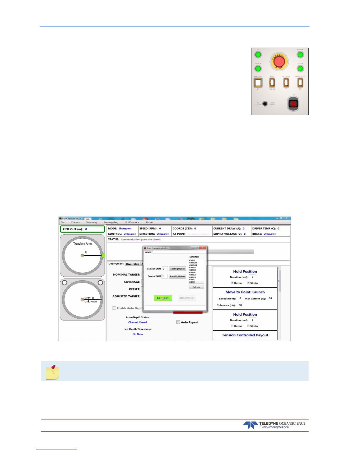
Connecting the Winch to a PC
To connect the winch to the PC and verify communication:
1. Apply power to the Control Module, follow Power Up Sequence .
2. Start the RapidCAST Interface software. The Select Communication Ports dialog will open. To reopen this screen, click the Comms menu.
3. Select the Serial COM Ports that were assigned in Step 1 of Installing Drivers and Software.
Lower COM Port number for the Telemetry COM
Higher COM Port number for the Control COM
4. Once both the Telemetry COM and the Control COM have been assigned a COM Port Number, click the Connect button.
Figure 28. Assigning the COMM Ports
This step must be done each time the RapidCAST Interface software is started.
Page 43
rapidCAST User’s Guide March 2018
EAR-Controlled Technology Subject to Restrictions Contained on the Cover Page.
Page 37
Verifying Basic Motion Functionality
The purpose of this section is to explain simple tests that should be performed on a newly-installed winch
to verify that it is operational.
To verify basic motion functions:
1. Turn power ON using the Power Up Sequence.
2. Start the rapidCAST Interface software.
3. On the Control Module, set the Control Switch to the Local Control position.
4. Use the joystick to pay OUT and pay IN a few meters of cable. See Line Management and Check
for Fouling when playing out line.
5. Observe the LevelWind and line as it is comes off the spool. The direction of the LevelWind travel
and the direction cable is comes off the spool should match. See Adjusting the LevelWind Position
if an adjustment is needed.
6. While paying OUT cable, press the Emergency Stop button on the Control Module. Verify that
the break is engaged on the winch and power is off to the Control Module. ALL LEDs off except
for Aux 24V, see LED Functions.
7. Reset the Emergency Stop button and verify that the system powers up.
8. On the Control Module, set the Control Switch to the PC Control position.
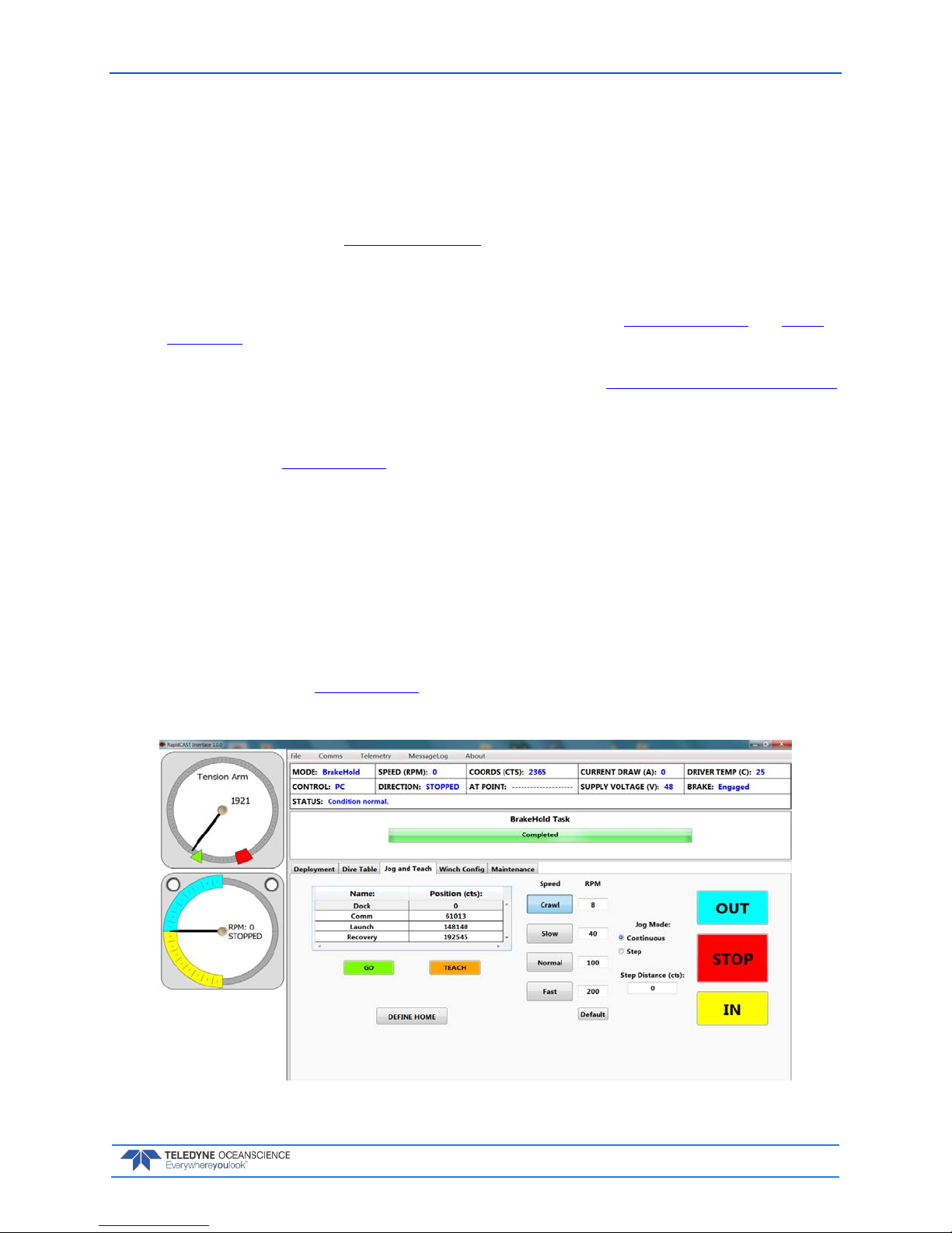
9. In the software, open the Jog and Teach tab.
a. Click the Crawl button to set the speed to 8 RPM.
b. Set Jog Mode to Continuous.
c. Use the In, Out, and Stop buttons to deploy and retract a few meters of cable.
10. While deploying cable, press the Emergency Stop button on the Interface Module. Verify
that the break is engaged on the winch and power is off to the Control Module. ALL LEDs off except for Aux 24V, see LED Functions.
11. Reset the Emergency Stop button and verify that the system powers up.
Figure 29. Jog and Teach Tab
Page 44

March 2018 rapidCAST User’s Guide
Page 38
EAR-Controlled Technology Subject to Restrictions Contained on the Cover Page.
Adjusting the LevelWind Position
As line is deployed in or out, the direction of the LevelWind travel and the direction the line as it is rolled
off the spool should be in-line with each other. T he Level Wind’s reciprocating motion is generated entirely
mechanically via rotation of a diamond screw. The LevelWind Drive Belt links the diamond screw to the
spool. Spool rotation, in turn, drives the diamond screw. A pawl (dull blade) sits inside the diamond screw
grooves. As the diamond screw rotates, the pawl traces the contour of the groove and drags the follower
along with it. When the end of travel is reached, the diamond screw thread loops back on itself, which
causes the pawl to reverse direction and travel the opposite way.
To adjust the LevelWind position:
1. Follow Lockout Procedure to prevent winch operation while adjusting the LevelWind.
2. Disengage the LevelWind pawl by pulling down.
3. Move the LevelWind to match the position of the line as it comes of the spool.
4. Engage the LevelWind spring pin by releasing it. Ensure that the pin is fully seated into the diamond screw groove.
5. Manually pull off line and observe that the when the LevelWind travels the line on the spool
matches the direction of travel and location so that line is pulled straight off the spool.
LevelWind Out of Sync LevelWind in Sync
Figure 30. LevelWind Adjustment
Page 45

rapidCAST User’s Guide March 2018
EAR-Controlled Technology Subject to Restrictions Contained on the Cover Page.
Page 39
Line Management
While the probe is in the water or hanging in the air, it pulls on the line and keeps it under tension. This
helps prevent line fouling.
When the probe is on deck, line is not normally under tension. If the spool is rotated outward while there
is no tension on the line, loose loops can form. An operator may not notice loose loops due to the winch
covers concealing the spool, and these loops may “hop” the spool sidewall or snag internal winch components and cause fouling.
When feeding line to someone holding the probe on deck, it is important to remember that line is flexible.
The winch is incapable of “pushing” line out, so line should always be “pulled” under tension by the person requesting additional line.
Keep the line under tension when rotating the spool to guard against fouling.
Figure 31. Line Management
Checking for Line Fouling
The easiest way to detect line fouling is to inspect the spool visually. Another indication of fouling is if the
probe moves in a direction opposite what you expect:
• If you rotate the spool out, yet the probe moves closer…
• If you rotate the spool in, yet the probe moves farther...
These may indicate that line is wrapped around something undesirable.
Page 46
March 2018 rapidCAST User’s Guide
Page 40
EAR-Controlled Technology Subject to Restrictions Contained on the Cover Page.
Defining Positions
The following positions are dependent on vessel speed and environmental conditions. If either of these
conditions changes significantly, re-evaluate the positions.
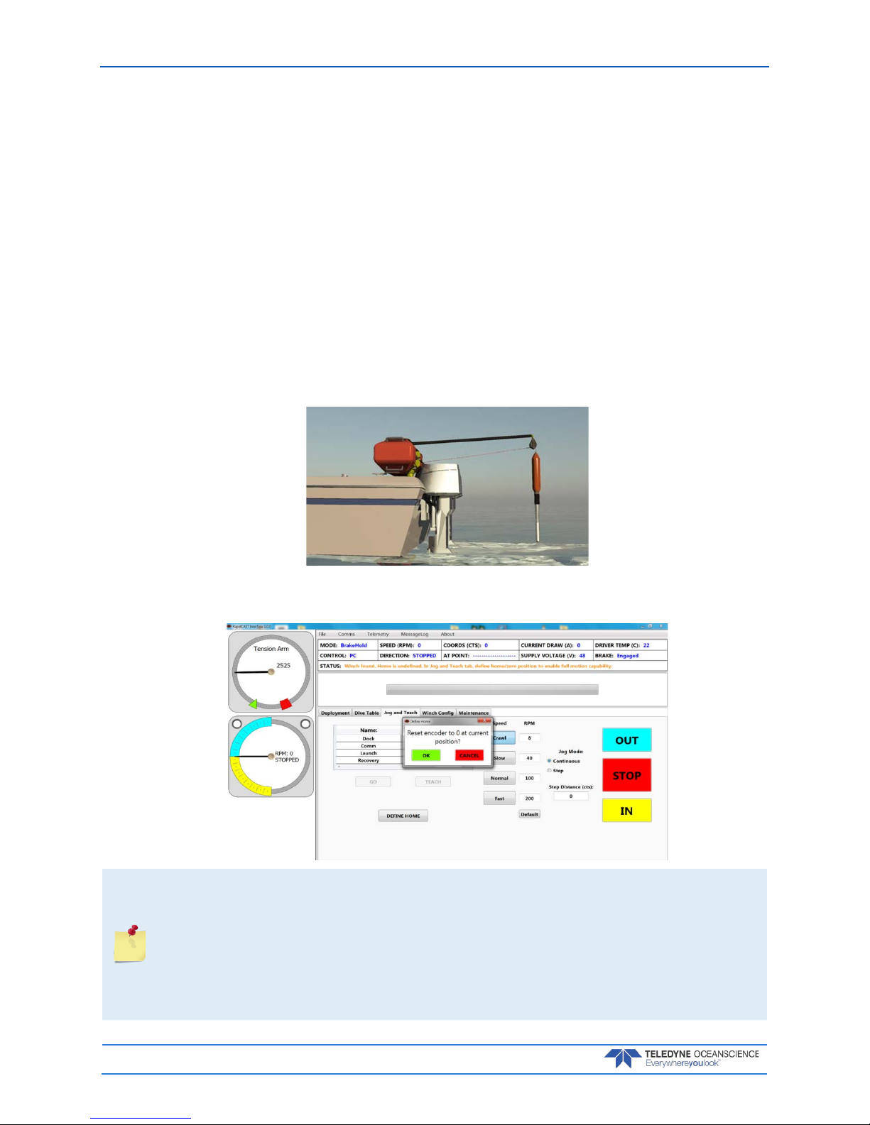
Setting the Home Position
The Home position is the absolute topmost position, where the probe can’t go up any further. This is the
position at which the encoder value is set to zero.
To set the Home position:
1. Turn power on to the system and start the rapidCAST Interface software.
2. On the Control Module, set the Control Switch to the Local Control position (joystick control)
or PC Control position (use the In, Out, Stop and Speed buttons on the Jog and Teach tab).
3. Move the probe to the topmost position next to the swivel block at the end of the davit.
4. Click the Jog and Teach tab on the rapidCAST Interface software.
5. Click the Define Home button. On the Define Home dialog, click OK.
This step must be done each time the rapidCAST system is powered up.
The winch uses incremental encoders to track the spool position. Unfortunately, incremental
encoders lose their value when power is lost (winch is turned off). When power is regained
(winch is turned on) they always initialize at zero. So, if the winch is currently at the Launch
position, which originally had an encoder value of 12345 and then somehow power is lost at
this position and subsequently regained, the encoders will now think that they are at value 0
(which is not the case). To recover from this, the probe needs to be manually moved to the
home position and then the Home position is set once more.
Page 47
rapidCAST User’s Guide March 2018
EAR-Controlled Technology Subject to Restrictions Contained on the Cover Page.
Page 41
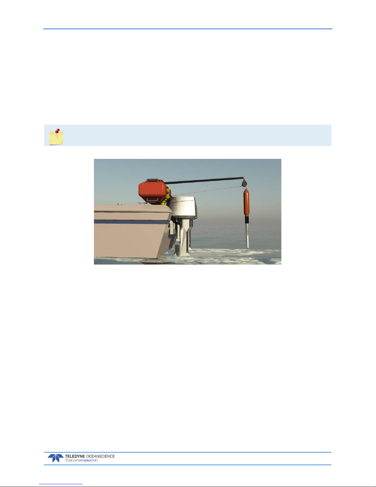
Dock Position
The Dock position is where the probe is completely out of the water and at the topmost position next to
the swivel block at the end of the davit. This is the position the winch will go to if the user wishes to bring
the probe back on board and is ready to swing the davit around to the deck.
To define the Dock Position:
1. Move the probe to the topmost position next to the swivel block at the end of the davit.
2. Click the Jog and Teach tab on the rapidCAST Interface software.
3. Click Dock and then click the Teach Button. On the Record Position dialog, click OK.
Home and Dock are essentially the same position.
Figure 32. Dock Position
Page 48

March 2018 rapidCAST User’s Guide
Page 42
EAR-Controlled Technology Subject to Restrictions Contained on the Cover Page.
Comm Position
The Comm position is where the probe antenna is out of the water and is able to communicate with the
Bluetooth antenna. The front of the probe is in the water to maintain stability.
To define the Comm Position:
1. Move the boat forward at the desired survey speed.
2. Move the probe to where the probe antenna (the black portion of the probe) is out of the water.
3. Click the Jog and Teach tab on the rapidCAST Interface software.
4. Click Comm and then click the Teach Button. On the Record Position dialog, click OK.
Figure 33. Comm Position
The Comm Position will be closer to the vessel at slower speeds and farther out at higher
speeds due to the hydrodynamic characteristics of the probe.
The Comm Position may require updating during operation due to the line packing effects on
positional accuracy. As the line is wetted and tensioned during recovery, the Comm Position
could drift and will be further away from the ship than the intended position. In this case, redefine the Positions and continue the survey.
Page 49

rapidCAST User’s Guide March 2018
EAR-Controlled Technology Subject to Restrictions Contained on the Cover Page.
Page 43
Launch Position
The Launch position is located just outside the wake. This is the position you want the probe to be at just
before initiating the tension control algorithm.
To define the Launch Position:
1. Begin moving the boat forward.
2. Move the probe to just outside the wake.
3. Click the Jog and Teach tab on the rapidCAST Interface software.
4. Click Launch and then click the Teach Button. On the Record Position dialog, click OK.
Figure 34. Launch Position
Recovery Position
Typically set the Recovery position farther out from the Launch position. After the tension-controlled
payout has finished, the rapidCAST will start reeling the probe back in. The reel-in speed can be fairly
high (up to 200 RPM). The Recovery position is the point at which you are comfortable having the probe
Page 50

March 2018 rapidCAST User’s Guide
Page 44
EAR-Controlled Technology Subject to Restrictions Contained on the Cover Page.
return to the boat at potentially high speed. Once the probe reaches the Recovery position, the reel-in
speed will slow down when near the boat for safety and peace of mind.
To define the Recovery Position:
1. Begin moving the boat forward.
2. Move the probe to beyond the wake.
3. Click the Jog and Teach tab on the rapidCAST Interface software.
4. Click Recovery and then click the Teach Button. On the Record Position dialog, click OK.
Figure 35. Recovery Position
Page 51

rapidCAST User’s Guide March 2018
EAR-Controlled Technology Subject to Restrictions Contained on the Cover Page.
Page 45
Saving and Loading Workspaces
The rapidCAST can save all of the settings for communications, Dock, Comm, Launch, and Recovery positions, and Configuration Settings to a Workspace file (*.rcstprj file). The settings will be lost in the event
of a power cycle and can be recovered if they are saved.
To save a Workspace file:
1. Click File, Sa v e Wo r kspace.
2. Name the file and click Save. The *.rcstprj file extension will be added automatically.
To open a Workspace file:
1. Click File, Open Workspace.
2. Locate the file and click Open.
Figure 36. Workspace Files
Page 52

March 2018 rapidCAST User’s Guide
Page 46
EAR-Controlled Technology Subject to Restrictions Contained on the Cover Page.
Quick Review
Check that the
communication ports are
assigned.
Reference page 36
Check the Basic Motion
Functionality
Reference page 37
Check that the Home,
Dock, Comm, Launch, and
Recovery positions are set
Reference page 40
Page 53

rapidCAST User’s Guide March 2018
EAR-Controlled Technology Subject to Restrictions Contained on the Cover Page.
Page 47
Curve Fitting & Dive Table Creation
When gravity is the primary force acting on the probe, its depth can be predicted via a ballistic dive table.
The Dive Table is used to model the probe fall behavior during the deployment. Two tail spool options are
possible.
• Tailspool with buoyancy module is used for deployments <100m to gain greater accuracy
• Plain tailspool is used for deployments >100m
To switch between pre-defined dive tables:
1. Start the rapidCAST Interface software.
2. Click the Dive Table tab.
3. The CURRENT DEPTH-TO-TIME COEFFICIENTS IN USE table shows the currently used dive
table. To swap tables, select the Alternate Choice in the second table and click the Activate Se-
lected Row button.
The orange buoyancy tail spool module has a maximum depth rating of 100 meters. If you are
deploying deeper than 100 meters, switch to the plain tailspool.
If you have a new probe or are operating in an environment with varying water conditions, a
new dive table will need to be created. Please contact technical support for further assistance
with this.
Page 54

March 2018 rapidCAST User’s Guide
Page 48
EAR-Controlled Technology Subject to Restrictions Contained on the Cover Page.
Using Auto-Depth
If Auto-Depth is enabled, the target depth is automatically set via NMEA 0183 messages from a depth
sounder. DBT, DPT, DBK, and DBS sentences are supported. Serial communication is the supported
transmission protocol in this initial release. NMEA messages may be input to the rapidCAST Interface via
a physical serial port or a virtual serial port.
In cases where rapidCAST Interface and the hydrographic survey software both reside on the same PC, a
virtual serial port may be the easier option to implement. If the survey software is already receiving
NMEA messages to perform its job, and if it has data re-broadcast capability, the survey software may regurgitate the NMEA data through a virtual serial port, which rapidCAST Interface can connect to, without
requiring physical cabling.
Third-party software can be used to create virtual serial ports. This feature has been successfully tested
with EIVA NaviScan survey software working in conjunction with virtual serial ports provided by Eltima
Software, for example.
What Auto-Depth Does and Does Not Do
Enabling Auto-Depth simply allows the NMEA stream to automatically populate the “Nominal Target
Depth” field as depth readings are received on-the-fly. For operational safety, it does NOT automatically
deploy the probe without human authorization. An operator must still decide when to start the deployment sequence.
Nominal Target Depth is updated as each valid depth reading is received. This happens continuously until
the tension-controlled deployment has started to ensure that the newest depth information is used up to
the moment it is needed. Once probe freefall has started, a “Paused for Deployment” status message will
indicate that the Nominal Target Depth is intentionally left unchanged for the duration of the cast, so that
the user knows the depth that is being targeted. When the cast is finished, NMEA messages will resume
updating the target depth.
Page 55

rapidCAST User’s Guide March 2018
EAR-Controlled Technology Subject to Restrictions Contained on the Cover Page.
Page 49
Auto-Depth Customizable Parameters
Limit nominal target depth to [X] meter(s) maximum - The user can specify the maximum target
depth that Auto-Depth is allowed to set. If you are operating in deep waters and only want to profile the
upper 100 meters, for example, you can set this parameter so that any depth readings that are deeper are
capped to this value.
Timeout if no new readings received after [X] second(s) - Auto-Depth and Auto-Repeat will be
disabled if the NMEA stream has stopped and no valid readings are received within a user-selectable expiration time. If this happens in the middle of a deployment, the current deployment will be allowed to complete, but with Auto-Repeat disabled, additional casts will not be performed without operator authoriza-
tion. This feature ensures that if contact with the depth sounder is lost, rapidCAST Interface will not be
using old/outdated depth data. For operational safety, if depth readings resume, the user must manually
re-enable Auto-Depth and/or Auto-Repeat, as desired.
Use shallowest value from the last [X] depth reading(s) - This feature reduces the probability of
the probe hitting the seafloor if surveying in a complex environment with rapidly changing depths, or if
depth sounder readings are fluctuating/noisy. From a candidate pool of the most recent depth readings,
the shallowest of these readings is chosen as the target. The user can customize the size of the candidate
pool. If the user does not wish to select shallower alternatives, this value can be set to 1, causing the candidate pool to consist of only one reading, which defaults to the newest depth.
Transducer offset from waterline: [X] meters - Nominal Target Depth is specified as the desired
probe depth measured from the surface. Because the depth sounder may be mounted on different parts of
the vessel (along the keel versus off to the side, for example), the depth reported by the transducer may be
offset from the waterline. If a transducer is mounted 1.3 meters below the waterline, and it reports a DBT
value of 15 meters, the actual depth from the surface is 15 + 1.3 = 16.3 meters. The value of [X] in this example should therefore be set to 1.3. This value will be added to each depth reading, correcting each one
to be relative to the surface. This offset may also be negative, if the user wants to subtract a fixed value
from each reported depth.
Reject sentences with bad NMEA checksums - The NMEA 0183 Standard specifies a checksum
value to be appended to the end of every sentence in order to guard against possible message corruption.
The sender of the message calculates a checksum based on the contents of the sentence that it is about to
send, and embeds that value at the end of the sentence. The receiver of the message should also calculate a
checksum based on the contents of the sentence that it has received. The sender’s checksum and the receiver’s checksum should match. If they do not, this indicates that the contents of the sentence have been
altered by noise or communication errors.
Page 56

March 2018 rapidCAST User’s Guide
Page 50
EAR-Controlled Technology Subject to Restrictions Contained on the Cover Page.
If Reject sentences with bad NMEA checksums is checked, the rapidCAST Interface will calculate
the checksums of each message received, and ignore sentences with invalid checksums, thus ensuring that
the reported depth readings have not been altered by communication noise.
However, it has been discovered that some depth sounders (which otherwise operate correctly in every
other respect) occasionally miscalculate the checksum value and provide bad checksums regardless. Some
transducers have also been encountered that do not provide checksums at all, in contravention to the
standard. If a user encounters this situation and wants to make use of the provided messages anyway, this
setting should be unchecked.
Message to use - Users should specify the expected message type (DBT, DPT, DBK, or DBS) to use for
extracting depth information. If more than one of these message types are present in the NMEA stream,
the user must choose one to use (ideally the message that gives the most reliable depth readings).
Auto Depth Status
Auto Depth Status informs the operator of Auto-Depth state.
Possible status messages are:
• Channel Closed: The NMEA communication channel is closed and not receiving messages.
• Channel Open: The NMEA communication channel is open and waiting for messages, but no
valid messages have yet been received.
• Timeout: The allotted time to receive a new NMEA message has expired, causing Auto-Depth
and Auto-Repeat to be deactivated.
• Ready: Valid NMEA messages are currently being received and can be used to update the Nomi-
nal Target Depth if the user chooses to enable Auto-Depth.
• Paused for Deployment: During probe freefall, this indicates that Nominal Target Depth is
intentionally kept frozen to inform the user of the intended depth for the current cast.
• Error: An unexpected communication error is preventing NMEA messages from being read.
• Bad NMEA Checksum: Appears only when Reject sentences with bad NMEA checksums
is checked. This is reported if a checksum mismatch has been detected for the latest NMEA message, causing it to be rejected.
• Last Depth Timestamp reports the PC clock time when the last depth reading was received.
This should continually update while depth data is streaming. If this timestamp has stopped, valid
depth values are no longer being received, and if stopped for long enough, a Timeout condition
will result.
Using Coverage
In the ideal case, a properly-fitted dive table ensures that the probe will end up slightly shallower than its
target depth (i.e., the possibility of the probe impacting the seafloor is minimal). With an optimal dive table, there is reasonably good agreement between the planned target depth and the actual depth achieved
by the probe during each cast. In this ideal situation, no adjustments are necessary.
If operating conditions or probe drop behavior changes drastically, the dive table may no longer be reliable, and the probe may end up significantly deeper or shallower than the intended depth. The ideal remedy is to redefine the dive table to match current conditions, but collecting data for a new dive table takes
time and effort.
As a crude alternative, adjustments can be applied to the Nominal Target Depth, increasing or decreasing
it as necessary, to reduce the gap between intended depth and actual depth.
Page 57

rapidCAST User’s Guide March 2018
EAR-Controlled Technology Subject to Restrictions Contained on the Cover Page.
Page 51
An Offset parameter allows a user to add a positive or negative distance to the Nominal Target Depth to
“tweak” the depth that is ultimately fed to the dive table, so that the actual achieved depth agrees more
closely with the intended target. For example, if the Nominal Target Depth is 30 meters, and it is discovered that the current dive table is achieving an actual probe depth of 28 meters, an Offset of 2 meters can
be entered to make the probe fall deeper. Conversely, if the Nominal Target Depth is again 30 meters, but
the actual depth overshoots the target and is 31.5 meters, a negative offset of -1.5 meters can be entered to
adjust the depth shallower. The Offset parameter is additive: positive offsets will make the probe fall
deeper, negative offsets will make it fall shallower.
RapidCAST Interface 1.5.1 introduces a multiplier factor called Coverage. Coverage is a positive-valued
parameter that can adjust Nominal Target Depth from 0% thru +100% to give the user increased flexibility in specifying a correction factor. In the context of depth correction, these fields take on the following
meaning:
Nominal Target Depth: The depth which the user truly wants to achieve with the probe; the actual
goal.
Adjusted Target Depth: The corrected depth that is passed to the dive table in order to achieve the
Nominal Target Depth. This is the “tweaked” depth that is feed the dive table in order to coerce it into
achieving the nominal depth, in reality.
Nominal Target Depth * (Percent Coverage / 100) + Offset = Adjusted Target Depth
If no adjustments are necessary, Coverage should be 100% and Offset should be 0 meters, in which case
the dive table will receive the Nominal Target Depth as-is.
Beyond acting merely as a corrective multiplier, an alternate interpretation for Coverage can
be found in the context of Auto-Depth: Assuming an accurate dive table, now that a depth
sounder can measure the depth to the seafloor and can set the Nominal Target Depth to this
value automatically; the user can specify percent coverage of this depth. For example, if the
user wants the probe to cover 90% of the water column, Percent Coverage can be set to
90%.
Using Auto-Repeat
After the deployment sequence has been started by the user, hands-free automation comes in the form of
the Auto-Repeat checkbox being checked. If Auto-Repeat is enabled, the deployment sequence will
automatically repeat at the conclusion of each cast. A user-selectable wait period can be specified via the
final Hold Position task to give the probe time to download its data before being deployed again and/or to
control the frequency of automated casts. If Auto-Repeat is not checked, the winch remains stationary
until the user starts the next cast.
Page 58

March 2018 rapidCAST User’s Guide
Page 52
EAR-Controlled Technology Subject to Restrictions Contained on the Cover Page.
Performing Your First Cast
C ASTING INCLUDES THE FOLLOWING STEPS:
Step 1 – Setup
Step 2 - Set Target Depth
Step 3 – Set Parameters
Step 4 - Launch
Step 5 - Tension Controlled Payout
Step 6 – Recovery
Step 7 – Communication and Data Download from Probe
COMM
LaunchRecovery
Page 59
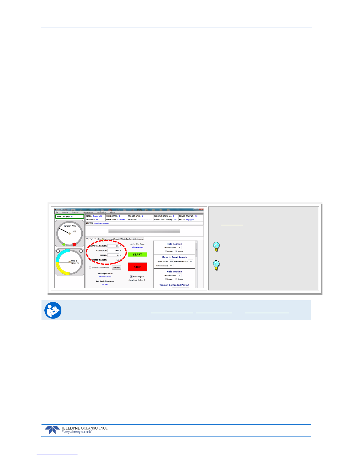
rapidCAST User’s Guide March 2018
EAR-Controlled Technology Subject to Restrictions Contained on the Cover Page.
Page 53
Step 1 –Setup
The training probe should be used for the first 2 to 3 casts every day to ensure proper setup and functionality.
1. Perform detailed inspections:
a. Line is routed correctly through LevelWind, tension arm, and pulley block.
b. Line is tight on the spool and not tangled.
c. LevelWind is in sync with line.
d. Line is not damaged and the loop splice is in good condition.
e. Tension arm moves smoothly when tension is applied to line.
f. Tailspool shackle is free from defects, scratches, or anything that may damage the line.
2. Attach the desired tailspool to the line, see Installing and Connecting the Probe
3. Slowly lower the probe into the water by holding the line and slipping it out by hand
4. Check that swivel is locked or unlocked in the desired position
Step 2 – Set Target Depth
Start the rapidCAST system and verify that the Home,
Dock, Comm, Launch, and Recovery positions are set
(see Initial Setup). Check the selected Dive Table.
Click the Deployment tab.
Enter the Target Depth for the probe.
Leave the Offset set to zero and Coverage set to
100% for the first casts.
When Auto Repeat is checked, once the start
button is checked, the deployment sequence will
automatically repeat at the conclusion of each cast
until Auto Repeat is unchecked.
For more information, see Using Auto-Depth, Using Coverage, and Using Auto-Repeat.
Page 60

March 2018 rapidCAST User’s Guide
Page 54
EAR-Controlled Technology Subject to Restrictions Contained on the Cover Page.
Step 3 – Set Parameters
If you want to enter a delay between steps, enter a number of seconds in the
Hold Position boxes.
Select Buzzer and/or Strobe to add warnings between steps as needed.
Recommended setting:
Enter a delay of 1 to 5 seconds between steps except for the hold position
between Tension Controlled Payout and Move to Point Recovery. This hold
duration should be equal to the Tension Controlled payout duration. This will
help in the initial retrieval of the probe by using the boat’s forward speed.
Select the Buzzer for the first step only. Use the Strobe for the rest of the
positions.
The software sequence will execute the following
actions, in order. The actions have a default setting
and are all user settable.
Review the settings by scrolling through:
Hold Position – time before next task begins with an
audio/visional notification option.
Move to Point: Launch – move the probe to launch
point defined in Jog and Teach tab.
Hold Position – time before next task begins with an
audio/visional notification option.
Tension Controlled Payout – Deploy probe for XX
seconds as defined in Dive Table tab.
Hold Position – time to hold probe using brake and
bring it to surface.
This Hold duration should be equal to Tension
Controlled payout duration.
Move to Point: Recovery – Recovery of probe to
recovery point defined in Jog and Teach tab.
Hold Position - time before next task begins with an
audio/visional notification option.
Move to Point: Comm - Recovery of probe to comm
point defined in Jog and Teach tab.
Hold Position – option to signal cast completion with
an audio/visional notification.
Page 61
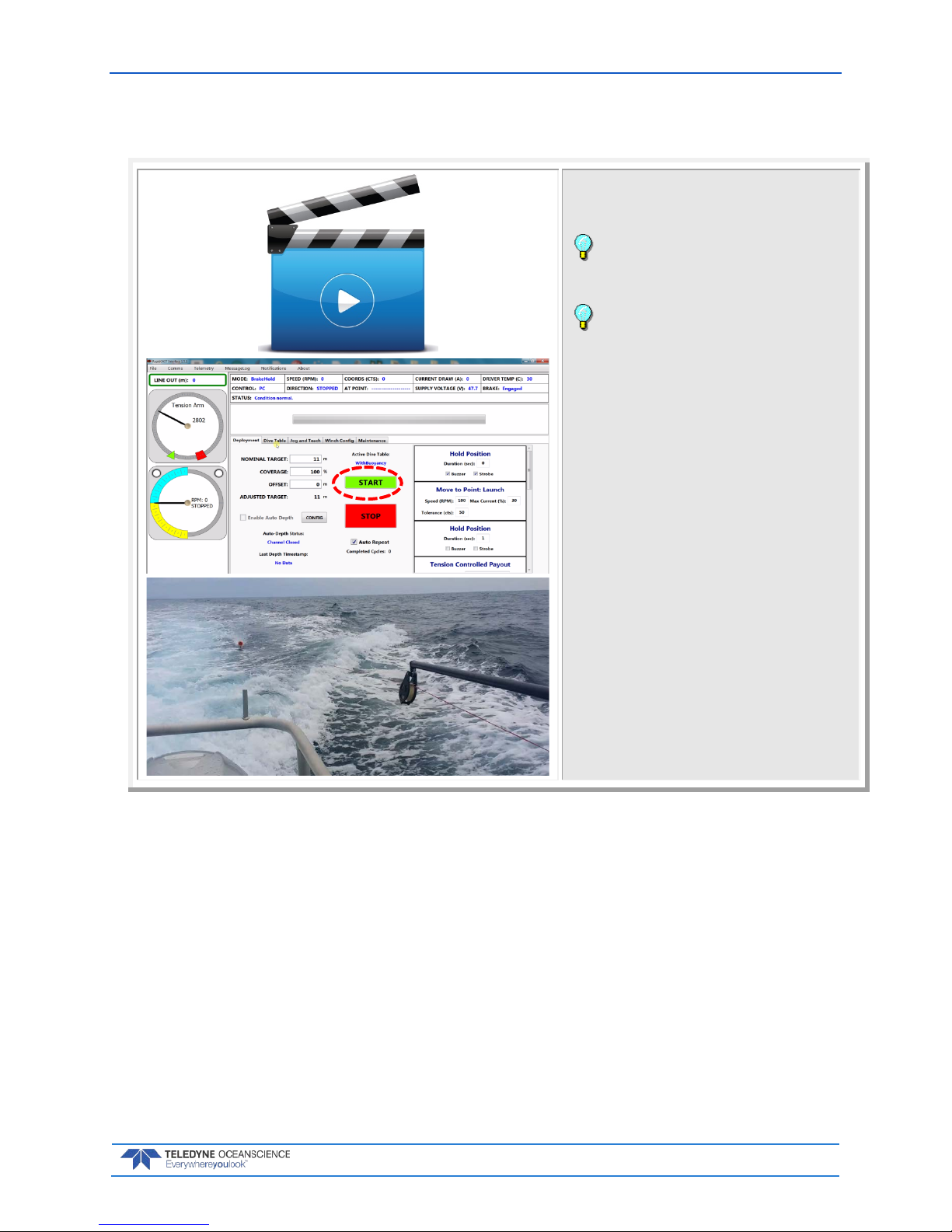
rapidCAST User’s Guide March 2018
EAR-Controlled Technology Subject to Restrictions Contained on the Cover Page.
Page 55
Step 4 – Move to Point Launch
Move the boat forward at the desired survey speed.
Click the Start button.
Watch the video showing a rapidCAST
deployment.
When Auto Repeat is checked, once the start
button is checked, the deployment sequence will
automatically repeat at the conclusion of each cast
until Auto Repeat is unchecked.
Page 62
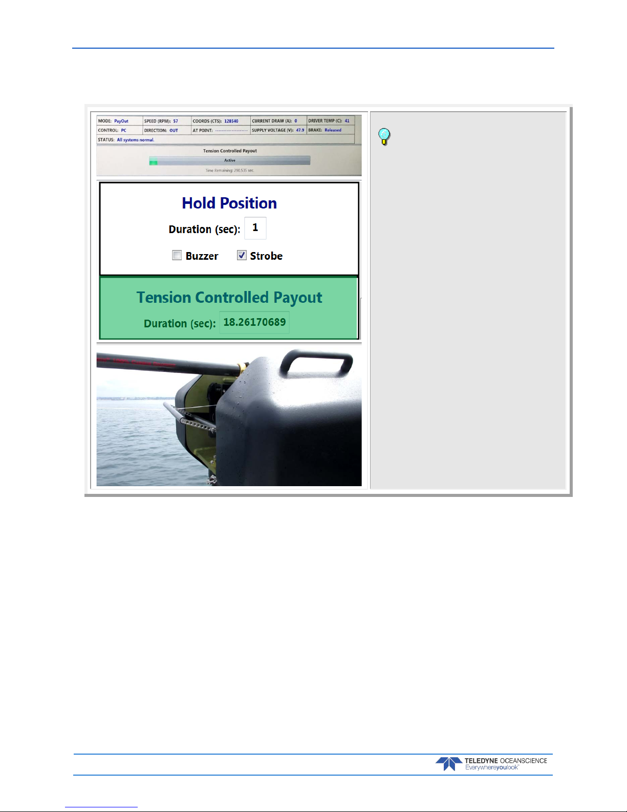
March 2018 rapidCAST User’s Guide
Page 56
EAR-Controlled Technology Subject to Restrictions Contained on the Cover Page.
Step 5 – Tension Controlled Payout
Observe the progress bar as each step is
completed.
Observe the winch tension control arm and line
Page 63
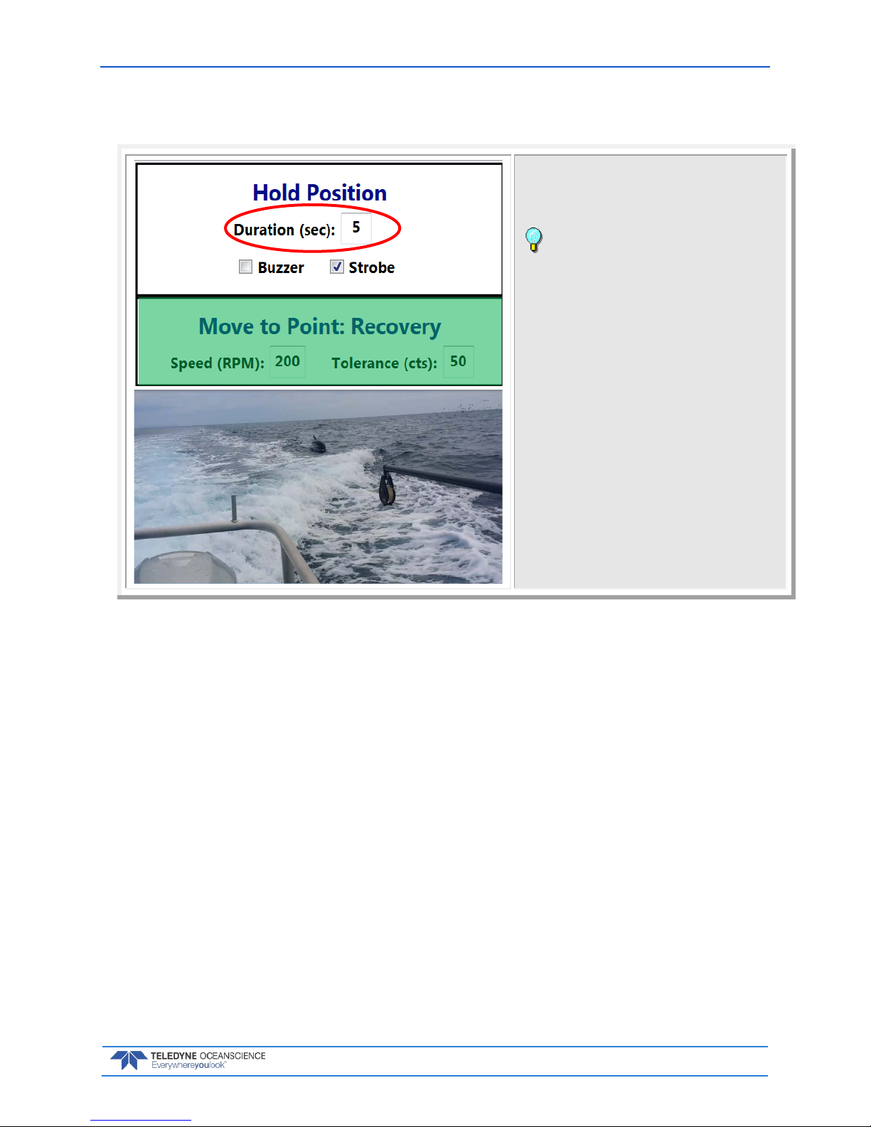
rapidCAST User’s Guide March 2018
EAR-Controlled Technology Subject to Restrictions Contained on the Cover Page.
Page 57
Step 6 – Move to Point Recovery
Observe probe as it is rapidly retrieved to the Recovery
position.
Set the Hold position before Recovery equal to
the Tension Controlled payout duration. This will help
in the initial retrieval of the probe by using the boat’s
forward speed.
Page 64

March 2018 rapidCAST User’s Guide
Page 58
EAR-Controlled Technology Subject to Restrictions Contained on the Cover Page.
Step 7 – Move to Point Comm
Once the probe returns to Recovery position the speed
will drop until the probe returns to the Comm position.
The probe software will open and data download over
the Bluetooth connection will begin.
Observe the progress bar as each step is
completed.
Observe the winch tension control arm and line
Observe the data download and depth the probe
obtained. If this depth is slightly different then the set
depth in step 2, use an offset for the next cast.
When Auto Repeat is checked, set the final Hold
Position long enough for the probe to download data.
The rapidCAST will start another cast until Auto Repeat
is unchecked.
Complete
That’s it! You completed a cast.
To start another cast, repeat steps 4 through 7.
Page 65
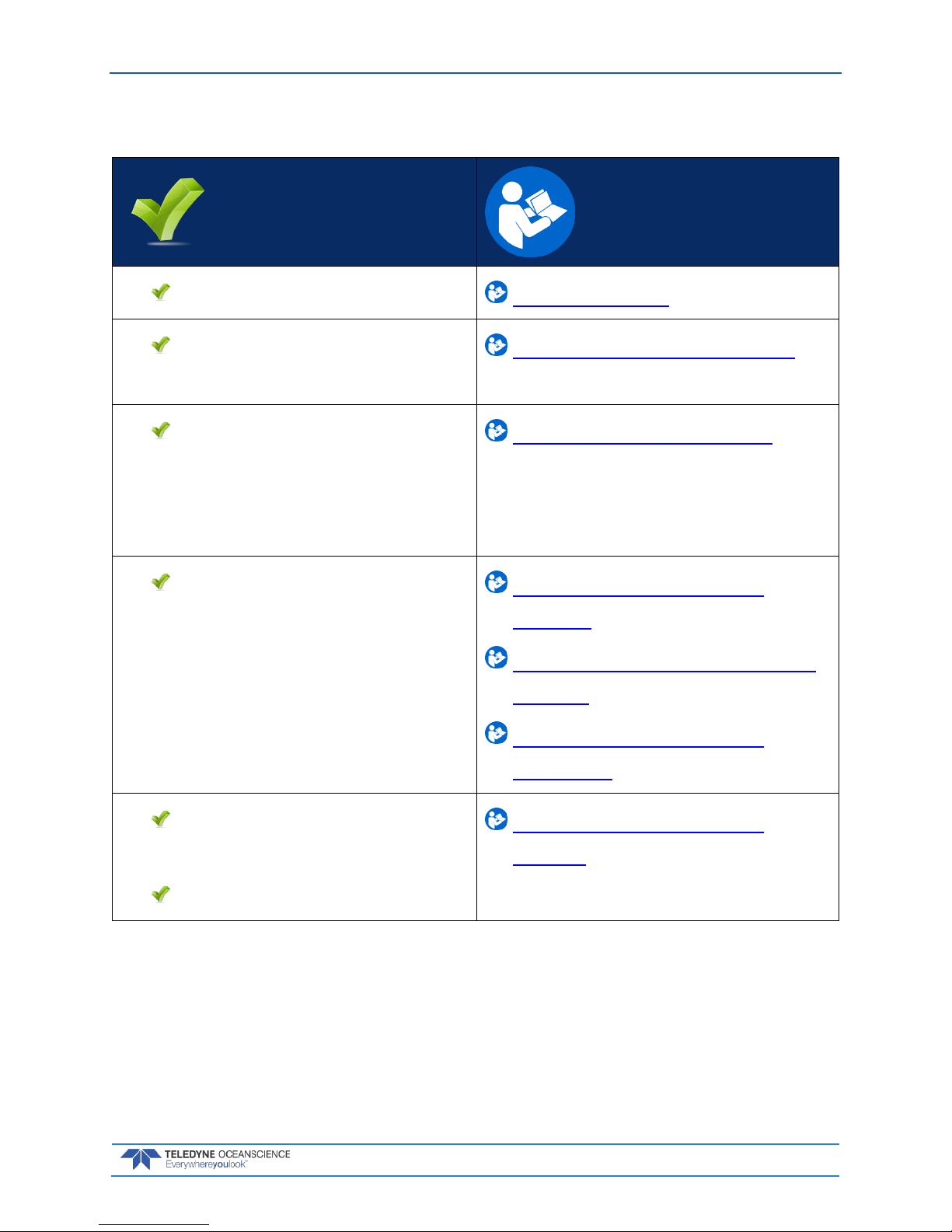
rapidCAST User’s Guide March 2018
EAR-Controlled Technology Subject to Restrictions Contained on the Cover Page.
Page 59
Quick Review
Setup and check system Step 1 - Setup
Check that target depth is
set
Step 2 – Set Target Depth
Review/Set Parameters
and verify hold positions
have been entered as
needed
Step 3 – Set Parameters
Check that rapidCAST
moves through
deployment steps
Step 4 – Move to Point
Launch
Step 5 – Tension Controlled
Payout
Step 6 – Move to Point
Recovery
Check that Data
Downloaded
Target Depth met
Step 7 – Move to Point
Comm
Page 66

March 2018 rapidCAST User’s Guide
Page 60
EAR-Controlled Technology Subject to Restrictions Contained on the Cover Page.
Disassembly and Packing
If the winch needs to be disassembled, use the following steps:
1. Power down the controller. Disconnect all cables on the controller and stow it in the Ancillaries
Case.
2. Remove the probe from the line and stow it in its case.
3. Secure the line to the spool using a piece of tape.
4. Remove the davit and stow it in its case.
5. Carefully lift the winch from the pipe mount. The cables should be removed from the winch pipe
and stowed inside of the winch prior to packing. It may be easier to remove the cover and wrap
the cables around the metal frame and the spool. Place the winch in its case.
Figure 37. Packing the Winch
DO NOT damage the tension arm when removing or wrapping the cables around the winch.
Page 67

rapidCAST User’s Guide March 2018
EAR-Controlled Technology Subject to Restrictions Contained on the Cover Page.
Page 61
Using the Configuration Settings
The Winch Configuration Settings should not be changed except under verify specific circumstances as
outlined in the Resolving Fault Conditions section.
To change a Winch Configuration Settings:
1. Start the rapidCAST Interface software.
2. Click the Winc h Co nf ig tab.
3. Locate the Parameter Name on the list and enter the DesiredValue.
4. Click the Commit All button.
Figure 38. Winch Configuration Settings
Page 68

March 2018 rapidCAST User’s Guide
Page 62
EAR-Controlled Technology Subject to Restrictions Contained on the Cover Page.
Resolving Fault Conditions
PROBLEM: The Control Module does not appear to be powered.
INDICATIONS: One or more LEDs on the Control Module are off.
DESCRIPTION: For normal operation:
The green 48V, Main 24V, and Aux 24V LEDs must all be lit
The green Activity LED must be blinking
The red Emergency Stop LED must be lit
An unlit LED indicates a lack of power to the corresponding subsystem, or a failure of the LED itself
(unlikely).
BASIC REMEDIES: (ensure that ALL of the following are satisfied):
Verify that the control module is receiving sufficient AC power. See Electrical Requirements sec-
tion.
Verify that Main Power and Motor Driver Switches are in the On position (upper halves are de-
pressed).
Ensure that Emergency Stop switches on the Control Module and Interface Module are released
in the up position.
Ensure that the Control Cable is connected between the Control Module and the Interface Mod-
ule. Disconnecting this cable is equivalent to pressing an Emergency Stop; this cable must be
connected for normal operation.
ADVANCED REMEDIES: (to be attempted if Basic Remedies do not resolve the issue):
1. Remove the four (4) Philips head screws on the lid and swing the cover open
2. Check the circuit breaker position is in the ON position, DOWN. The figure shows the circuit
breaker in the OFF position, UP.
Page 69

rapidCAST User’s Guide March 2018
EAR-Controlled Technology Subject to Restrictions Contained on the Cover Page.
Page 63
PROBLEM: The Motor Brake does not appear to be engaging/stopping the spool.
INDICATIONS: If the Control Module detects that the spool has rotated 10 or more revolutions
even after the brake has been commanded to engage, the following fault will be reported by the Interface
Software: “EXCESSIVE BR AK E SLIPP AGE DETECTED.” The Control Module will activate the Buzzer and
Strobe for 30 seconds if this fault is encountered.
DESCRIPTION: The spool is stopped by an electromagnetically-actuated brake, which functions
like a solenoid. When the brake is unpowered, a spring clamps the brake shut, preventing rotation of the
motor shaft. This ensures that in the event of a power loss, the spool will be stopped and the probe will be
retained. Applying 24V DC power to the brake will energize an electromagnet that separates the brake
pads, which will release the motor shaft and allow it to rotate freely. A solid-state relay inside the Control
Module determines whether 24V DC is applied to the brake.
Corrective action depends on whether the brake slippage is due to a mechanical or electrical fault, with a
mechanical cause being more probable. Mechanical causes are varied and may include anything from a
loose brake/motor set-screw or loose fasteners/couplers anywhere along the drivetrain. An electrical
cause might be the solid state relay’s failure to cut power to the brake (because the relay may have failed
short, and thus continues to conduct power even when it shouldn’t).
When brake slippage is detected, the motor will actively stop the spool and prevent further rotation. The
motor will substitute for the brake, though this should only be treated as an emergency feature and should
not be relied on for normal operation.
REMEDIES:
If the error is encountered while the probe is in the water, stop the vessel immediately to alleviate
the strain on the motor caused by drag. Excessive drag may cause the motor to fail due to overheating from high current, potentially leading to loss of the probe and damage to the winch.
Recover the probe and bring it on board.
Once the probe is safely stowed, turn the Main Power Switch OFF. Cutting power should cause
the brake to engage. Attempt to move the spool by hand. If the spool can be rotated, this indicates
that the root cause is most likely mechanical. If the spool cannot be rotated, an electrical cause
(faulty relay) is more probable. When attempting to move the spool by hand, apply a fair amount
of force, since the brake is designed to resist large loads. Partial slippage is an indication of a potential mechanical fault.
If a mechanical cause is suspected, remove the winch covers, remove the motor cover, and per-
form a careful inspection of the drivetrain starting from the brake and continuing to the spool.
Tighten any loose couplers/fasteners along the drivetrain, paying particular attention to collars
and set-screws.
If the brake relay is suspected, you may activate the backup brake relay. A secondary relay was
included in the design. The original (suspect) relay must first be disconnected, since a shorted relay will interfere with the operation of the backup relay. Open the Control Module and locate the
Processor Circuit Board. On this circuit board, disconnect the Brake Relay Out connector, which
is located just underneath the ribbon cable. Close the Control Module.
In the Interface Software’s Winch Config tab, set the UseBackupBrakeRelay variable to True.
This will bypass the original suspect relay. Please note that this setting is not retained if the Interface Software is closed. If you Save Workspace while this variable has the desired value, and later
Load Workspace, the variable will be set when loading the stored workspace.
If the brake cannot be repaired yet completing the survey is paramount, the motor can take the
place of the brake as long as survey depths are restricted to 100 meters or less and survey ves-
sels speeds are restricted to 6 knots or less. In all cases, deploying the probe without a functioning brake increases the risk of probe loss, especially if the motor becomes damaged during deployment and is unable to hold the probe. The importance of completing the survey versus the
value of the probe should be weighed carefully.
Page 70

March 2018 rapidCAST User’s Guide
Page 64
EAR-Controlled Technology Subject to Restrictions Contained on the Cover Page.
PROBLEM: The Motor Brake is not releasing the spool when commanded to.
INDICATIONS: One or more of the following conditions may indicate a brake failure to release:
• Unpleasant grinding noise when the spool is rotating.
• The spool appears to be struggling or shaking when rotating.
• The Interface Software reports unusually high current levels when attempting to move the spool.
• The Interface Software reports wide speed fluctuations when attempting to move the spool.
DESCRIPTION: The spool is stopped by an electromagnetically-actuated brake, which functions
like a solenoid. When the brake is unpowered, a spring clamps the brake shut, preventing rotation of the
motor shaft. This ensures that in the event of a power loss, the spool will be stopped and the probe will be
retained. Applying 24V DC power to the brake will energize an electromagnet that separates the brake
pads, which will release the motor shaft and allow it to rotate freely. A solid-state relay inside the Control
Module determines whether 24V DC is applied to the brake.
Failure of the brake to release is indicative of an electrical fault, since it requires electrical energy in order
to generate an electromagnetic force which releases the brake pads. Prime candidates include a malfunction of the brake relay and its inability to conduct current when needed, or a failure of the brake power
supply.
You may toggle the brake state to test its functionality:
On the Control Module, set the Toggle Switch to Local Control
Set the Brake Switch to Release and back to Brake, repeating this as many times as desired.
You should hear clicks coming from the motor housing, indicating that the brake is engaging and
releasing based on the switch position.
Remember to return the Brake Switch to Brake and the Toggle Switch to PC Cont ro l if you
want to use the Interface Software.
REMEDIES:
On the Control Module, verify that the MAIN 24V LED is lit. If this LED is not lit, this indicates
that the power supply for the brake has failed or is not supplying power. Using a Multimeter, verify the output of the power supply is 24VDC. If there is 24VDC output, then inspect all of the wiring in and out of the power supply. If the power supply has failed, this is a terminal condition. The
brake cannot operate until this power supply is replaced.
Disconnect the Motor Power Cable and inspect the connector for possible damage to the pins and
conductors. Ensure that this cable is properly seated when connected.
If the brake relay is suspected, you may activate the backup brake relay. In the Winch Config tab,
set the UseBackupBrakeRelay variable to True. This will bypass the original suspect relay. Please
note that this setting is not retained if the Interface Software is closed. If you Save Workspace
while this variable has the desired value, and later Load Workspace, the variable will be set when
loading the stored workspace.
If the brake cannot be released despite the above remedies, and the probe is still in the water, fol-
lowing the steps in the next section to remove the brake. Once the brake is removed, recovery using the motor should be possible.
Page 71

rapidCAST User’s Guide March 2018
EAR-Controlled Technology Subject to Restrictions Contained on the Cover Page.
Page 65
PROBLEM: Manual recovery of the probe is required and not possible by hand.
INDICATIONS: One or more of the following conditions may require a manual probe recovery:
• Power is no longer available from the vessel.
• The system is non-functional.
DESCRIPTION: The probe is in the water and the system is not functioning. Recovery by hand is
not possible because the line out is greater than 100 meters or the load on the line is too great to pull in
safely by hand.
REMEDIES: The spool is stopped by an electromagnetically-actuated brake. To physically uninstall
the brake and recover the probe:
Tools Required:
• (2) Flathead screwdrivers
• (1) Needle nose pliers
• (1) 5mm hex key
• (1) 9/64in hex key
1. Stop the vessel to reduce the drag exerted by the probe.
2. Remove the winch covers, specifically the center cover which hides the spool, as well as the motorside cover.
3. Lockout the system and disconnect the motor power cable from the top of the motor.
4. Secure the spool to prevent rotation either by tying rope from the slots in the spool to the rear of
the frame or have a crewmember hold the spool stationary to prevent rotation. Thick and sturdy
gloves are strongly recommended to protect the person’s hands in case of spool rotation.
5. Disassemble the motor power bulkhead connector.
a. Use a large tweezer to depress the two tabs in the connector (be careful – they break off
easily).
b. While the tabs are depressed, use pliers to pull on one of the connectors. This will remove
the power bulkhead.
c. Use a flathead screwdriver to remove the plastic lock pin in the bulkhead. This disen-
gages the power connectors and frees them from the bulkhead.
Page 72

March 2018 rapidCAST User’s Guide
Page 66
EAR-Controlled Technology Subject to Restrictions Contained on the Cover Page.
6. Remove the Brake:
a. Remove the twelve (12) X M6 screws and washers using a 5mm hex key.
b. Slide off the motor cover making sure the motor wires are no longer attached.
c. Remove the four (4) X #8-32 screws using a 9/64 hex key.
d. Slide off the brake.
7. Now that the brake has been removed, the spool is free to rotate, but it is still secured.
8. Recovery by hand is possible by rotating the spool IN manually.
9. Recovery using a power drill connected to the motor rear shaft is recommended if one is available.
The motor is connected to the spool through a reduction gearbox, which provides increased output torque and reduced output speed. The rotational speed of the spool will be less than the input
rotational speed of the drill.
a. In general, the drill chuck can be coupled directly to the shaft in the rear of the motor. Be
sure the chuck and motor shaft are clean and free from grease.
b. For maximum torque, a 7/8inch deep socket can be connected to the brake nut on the mo-
tor shaft. This will eliminate slippage of the drill chuck on the shaft, but may damage
the brake nut and hinder further operations with the system.
c. As you rotate the motor shaft using the drill, slowly release the spool to make sure the drill
has adequate torque to pull in the line.
d. STOP if the drill is unable to rotate the spool or if anything is abnormal. Inspect the setup
and try again if possible.
e. In case recovery with a drill is not possible, disconnect the drill and recover the probe by
hand, rotating the spool IN manually.
Page 73
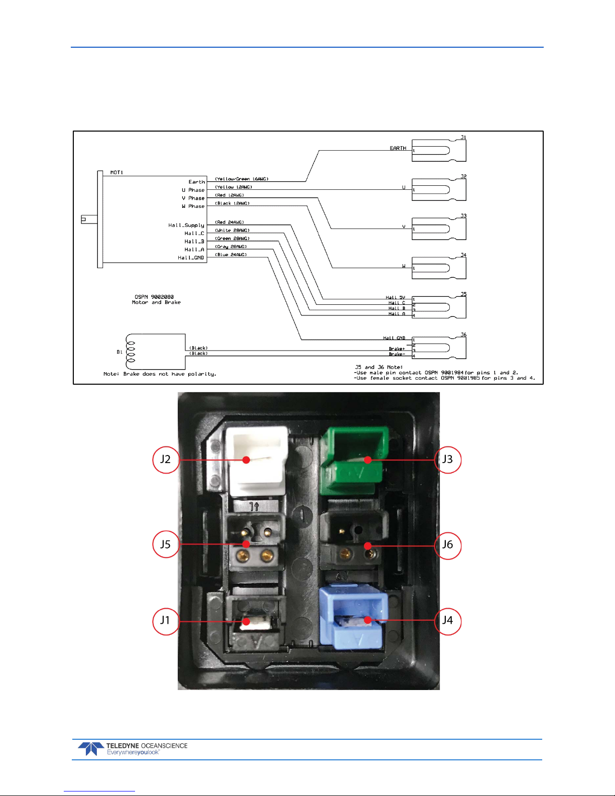
rapidCAST User’s Guide March 2018
EAR-Controlled Technology Subject to Restrictions Contained on the Cover Page.
Page 67
10. Once the probe has been safely recovered, the malfunctioning brake must be replaced before future deployments can proceed.
11. To install the NEW brake, reverse the above procedure starting with Step 6. Take care to re-install the power bulkhead contacts as shown below:
7000620 REV 03
Page 74

March 2018 rapidCAST User’s Guide
Page 68
EAR-Controlled Technology Subject to Restrictions Contained on the Cover Page.
PROBLEM: The Spool Encoder is malfunctioning.
INDICATIONS: Any of the following may indicate a problem with the spool encoder:
• Erratic spool motion during tension-controlled payout or when moving between points. Erratic
motion may include instantaneous unexpected speed changes or brief stoppages.
• Inconsistent or non-existent position count feedback. Feedback on the winch’s current position
may freeze or skip counts during motion.
• Inability of the winch to maintain a reasonably constant speed for extended periods, despite being
commanded to do so.
DESCRIPTION: Feedback on the spool’s position and speed is provided by an incremental optical
encoder with a resolution of 10,000 counts per spool revolution. By virtue of its extremely high resolution,
the spool encoder is a precision sensor whose performance can be degraded by moisture ingress, foreign
contaminants, mechanical misalignment, or extreme shocks or vibration. In addition to mechanical disturbances, sensor feedback from the encoder can also be corrupted by electrical noise when high levels of
electromagnetic interference are present. The spool encoder is a critical component of the motion control
system, and degradation in its performance will interfere with the ability to control the spool’s motion reliably and predictably.
REMEDIES:
1. If the probe is in the water, retrieve the probe and stow it on the vessel. Once the probe has been
stowed, on the Control Module turn the Motor Driver Switch OFF. Verify that the Activity LED
becomes dim, which confirms that the motor driver has been successfully deactivated. Turn the
Brake Switch to Release. Move the Control Source Toggle Switch to Local Control.
Detach the line from the probe. Secure all line onto the spool, and use adhesive tape or other fas-
tener to fix the end of the line to the spool so that the line cannot snag any objects. The goal is to
allow the spool to rotate freely.
2. Confirm that the spool encoder is indeed malfunctioning. Other sources of erratic motion may be
mechanical in nature such as loose couplers or mechanical obstructions. To rule out mechanical
sources of error, rotate the spool by hand and feel for any mechanical grittiness, looseness, or obstructions. If manual rotation of the spool feels smooth, this clears the mechanical system and
makes the spool encoder suspect. Set the Control Source Toggle Switch to PC Control and set all
power switches to their normal (up) positions at the end of this test in order to use the Interface
Software.
3. As additional confirmation that the spool encoder may be damaged, use the Interface Software to
command the spool to rotate without relying on feedback from the encoder. To deactivate the encoder, in the Interface Software Maintenance tab, click the Open Loop button and confirm that
the Mode setting on the dashboard indicates OpenLoop. This step deactivates feedback from the
encoder.
Afterward, in the Winch Config tab, locate the OpenLoopVelocityScaled setting. Entering a value
here will command the spool to rotate without encoder feedback. A positive value will cause the
spool to rotate out. A negative value will cause the spool to rotate in. A value of 0 will stop the
spool. The values do not correspond to RPM but correspond to percentages. For example: a value
of 1000 (interpreted as 100.0%) will make the spool rotate out at its maximum speed; a value of 1000 (interpreted as -100.0%) will make it rotate in at maximum speed; a value of -637 will make
the spool rotate in at 63.7% of its maximum speed; and a value of 50 will make it rotate out at
5.0% of its maximum speed.
Test and observe spool motion for different values of OpenLoopVelocityScaled. If spool motion is
smooth and predictable when the encoder has been deactivated, this confirms that the spool encoder is at fault.
4. Damage to the Spool Encoder is terminal. It must be replaced before the winch can be safely operated.
Page 75
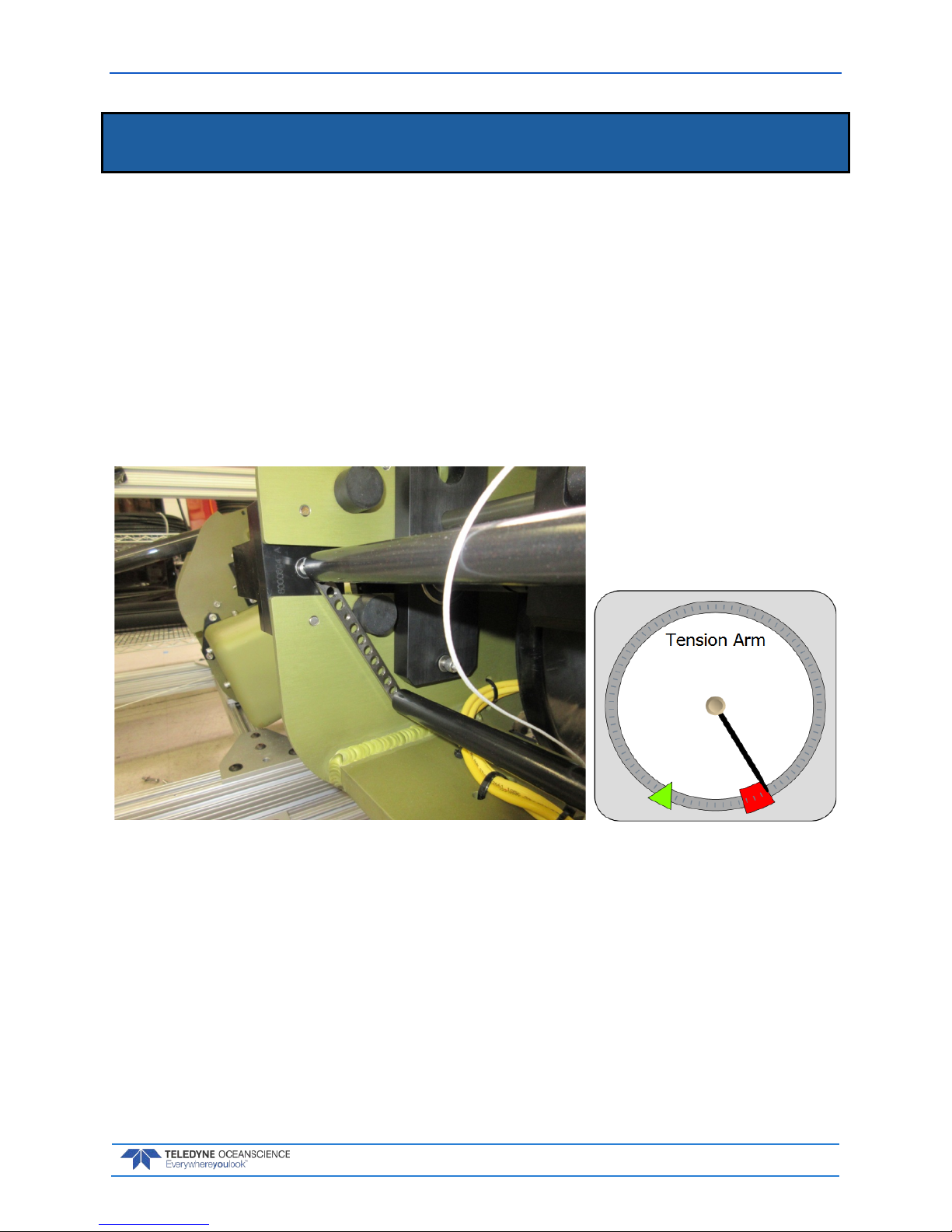
rapidCAST User’s Guide March 2018
EAR-Controlled Technology Subject to Restrictions Contained on the Cover Page.
Page 69
Tension Arm Calibration
Tension Arm calibration is a process that captures the Tension Arm’s operating characteristics and saves
these parameters in the Control Module. The Tension Arm is calibrated at the factory, and in most cases
re-calibration is rarely needed.
However, calibration should be performed if any of the following conditions apply:
• The Tension Arm or its Encoder is removed, replaced, or mechanically adjusted.
• The desired line tension for the Tension-Controlled Payout needs to be defined.
• The Control Module is paired with a different Winch.
• There is a discrepancy between the Tension Arm’s reported position in the software and its true
position.
The fastest way to verify the Tension Arm’s calibration is to remove all line tension from the arm, such
that the arm is resting freely against its lower hard stop.
When the Tension Arm is at its lowest position, the angular gauge in the Interface Software should show
the Tension Arm pointing at the far edge of the red zone. If the Tension Arm is not depicted at this position when the arm is fully relaxed, calibration is needed.
To create a new calibration:
1. In the rapidCAST Interface software, click the Maintenance tab and then click the Calibration
button (see Figure 39, page 71).
2. In the Calibration window, click the Save Backup File button to save the current (incumbent)
calibration to a file on the PC. Use the Browse File button to load the settings from a previouslysaved calibration file, if desired.
3. Safely stow the probe. Untie the line from the probe and ensure that the line is not attached to any
objects.
Page 76

March 2018 rapidCAST User’s Guide
Page 70
EAR-Controlled Technology Subject to Restrictions Contained on the Cover Page.
4. Remove all line tension from the Tension Arm so that the arm is resting against its lower hard
stop. Under Tension-Arm Minimum Position click the Capture button to record the arm’s
position.
5. Ensure that the line is routed through the LevelWind, Tension Arm, and Davit Pulley exactly as it
would be during normal operation. Choke the line around the provided 200 gram calibration
weight as shown below and allow it to hang freely.
6. Tug on the line to create excess tension, and then gently release the line so that the calibration
weight gradually settles into its free-hanging position. Under Tension-Arm Setpoint Position,
click the Capture button to record the arm’s position. This will set the line tension for TensionControlled Payout.
7. If you are satisfied with the captured positions, click the Apply button to commit these settings to
the Control Module. If you are unsatisfied, you may repeat the capture process as many times as
desired, or you may cancel the calibration simply by closing the Calibration Window. Once a new
calibration has been applied, the settings are stored in the Control Module’s flash memory. A copy
of the calibration file is also stored locally on the PC, as a backup in case the Control Module is
unable to access flash.
8. Cycle power to the winch controller; Make sure that the Calibration Source reads Winch
Controller (see Figure 39, page 71). Upon power cycling, the controller first checks the internal
source of the calibration which is the FLASH card and this is signified by the Winch Controller
source.
If the winch controller fails to find the FLASH stored values, then it reads the temporary file from
the local computer and displays PC as the source, indicating that there is a problem with the
FLASH card, the FLASH is not properly seated, the FLASH is missing, or there is a problem with
the CPU assembly.
Page 77
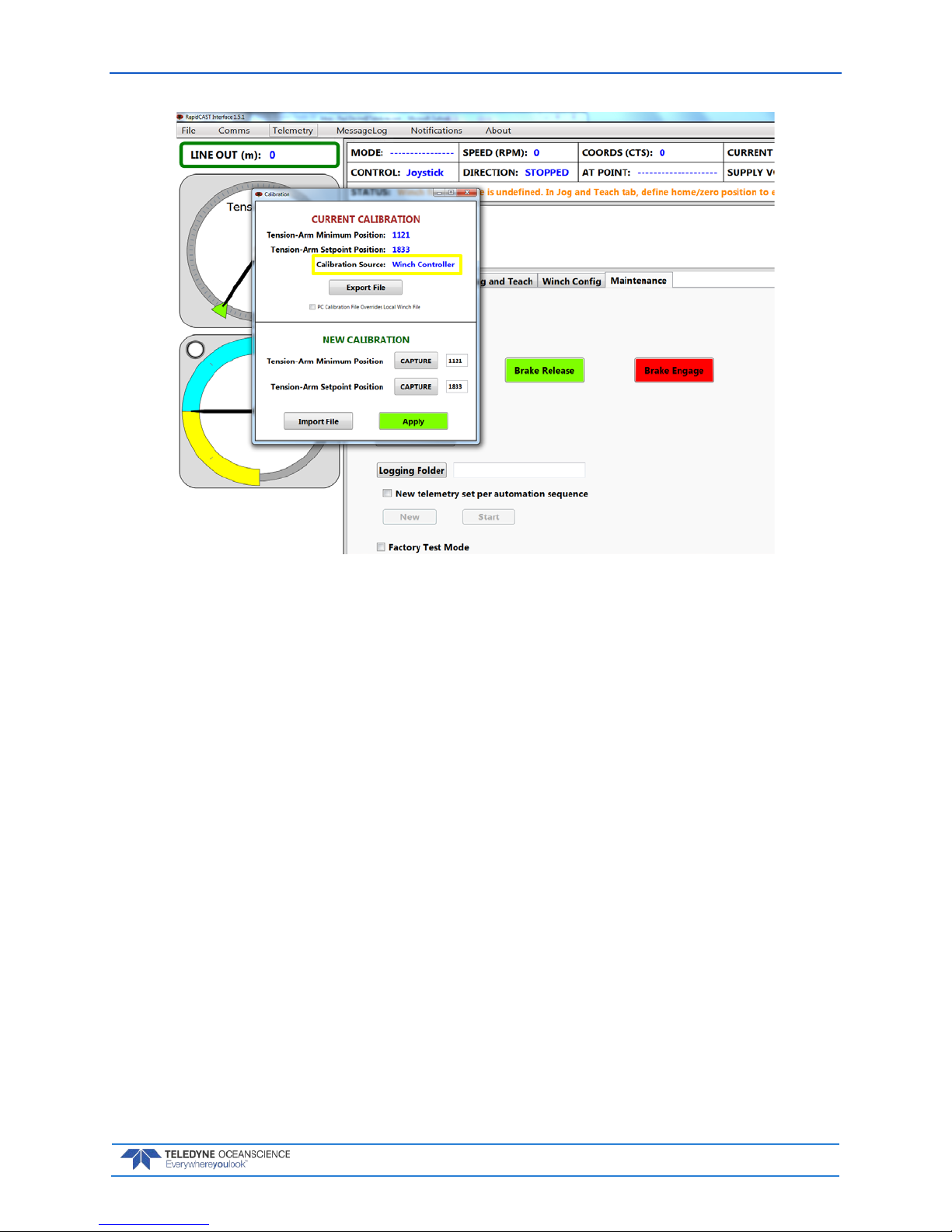
rapidCAST User’s Guide March 2018
EAR-Controlled Technology Subject to Restrictions Contained on the Cover Page.
Page 71
Figure 39. Tension Arm Calibration
H OW IS THE CALIBRATION DATA STORED, AND HOW IS IT RETRIEVED?
When you apply a new calibration, the calibration settings are stored in two places simultaneously:
• A microSD card inside the Control Module retains the calibration settings in flash memory.
• The calibration settings are also stored in a local file on the PC. The file resides in a (normally hid-
den) folder: C:\ProgramData\Teledyne Oceanscience\RapidCast Interface\[Version]\WinchCalibration.txt.
When the Control Module boots up, it checks the microSD card for the calibration settings. If the calibration settings cannot be found or if the card is inaccessible, the Interface software will automatically transmit the backup calibration data that is stored on the PC, so that the winch can operate normally.
Under Current Calibration, the Calibration Source field will identify whether the calibration data is
from the Control Module’s microSD card, or whether it is from the PC (see Figure 38, page 61).
The PC Calibration File Overrides Local Winch File checkbox allows you to force the Control Module to use the calibration data stored in the PC. This is useful if the on-board microSD card has malfunctioned and may be providing incorrect data and thus needs to be overridden.
Page 78
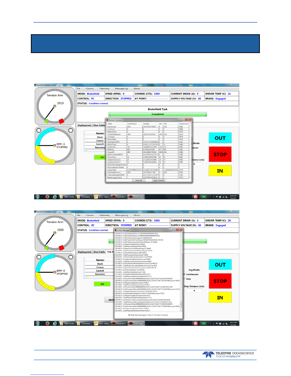
March 2018 rapidCAST User’s Guide
Page 72
EAR-Controlled Technology Subject to Restrictions Contained on the Cover Page.
Using the GUI Windows and Controls
The rapidCAST system keeps track of system performance in the Telemetry and Message Log windows. To
view the screens, click the desired menu item.
Telemetry menu:
MessageLog menu:
Page 79
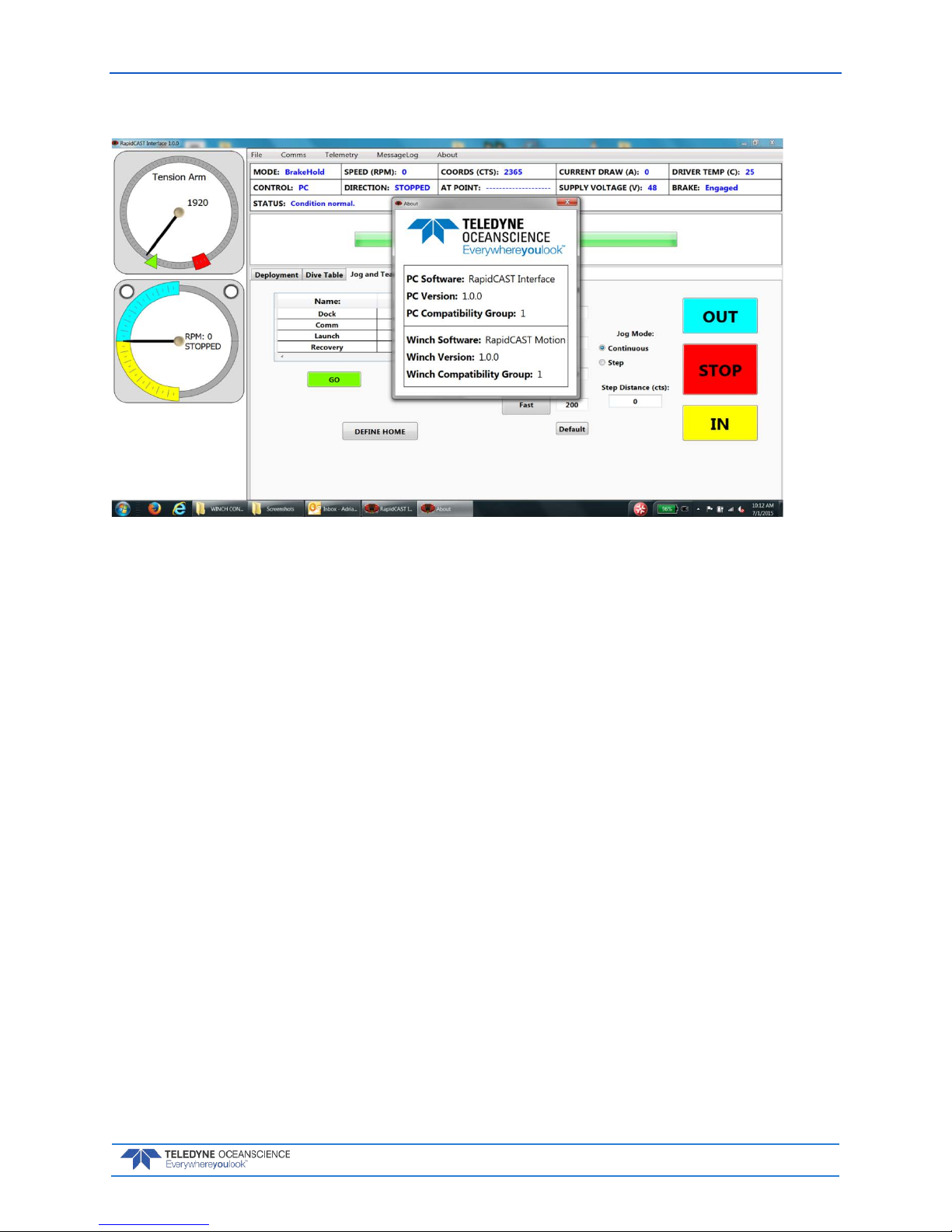
rapidCAST User’s Guide March 2018
EAR-Controlled Technology Subject to Restrictions Contained on the Cover Page.
Page 73
About menu:
Page 80

March 2018 rapidCAST User’s Guide
Page 74
EAR-Controlled Technology Subject to Restrictions Contained on the Cover Page.
Updating the Winch Software
To update the winch software:
1. Start the rapidCAST Interface software.
2. Click the Maintenance tab.
3. Click the Software Update button.
4. Click the File Location button and navigate to the folder that contains the Config.hex and Firm-
ware.hex files.
Updates may be sent via e-mail or downloaded from Oceanscience.
5. Click the Upload Files button.
Ensure that the winch has reliable power and is not interrupted during the flashing process,
otherwise software corruption may occur.
Page 81

rapidCAST User’s Guide March 2018
EAR-Controlled Technology Subject to Restrictions Contained on the Cover Page.
Page 75
Maintenance Procedures
The spare parts kit 71JK6004-00 includes parts, which are expected to wear out and need to be replaced
on a regular schedule.
Table 3. Spare Parts Kit 71JK6004-00
Part Number Description Quantity
8000585 SPRING, TENSION ARM, ALTERED ITEM 1
8000589 LevelWind Roller, Vertical, rapidCAST 2
8000595 LevelWind Roller, Horizontal, rapidCAST 2
81J-6000-00 SHACKLE, TAILSPOOL, UCTD 1
9000994 LINE, WINCH, RCAST/UCTD, 500LB, WHITE 1500.00 yards
9000996 LINE, WINCH, RCAST/UCTD, 800LB, RED 700.00 yards
9002064 Stainless Steel External Retaining Ring for 6mm Shaft Diameter 2
9002086 Quick-Release Pin, Type 316 Stainless Steel, 1/4" Diameter, 2.5" Usable Length 1
9002202 Trapezoidal Tooth Neoprene Timing Belt, .200" Pitch, Trade Size 220xL, 22" Outer Circle, 3/8"
Wide
1
9092K72 CAP, VINYL, 1.75" SQUAREX 1" INSIDE HEIGHT, BLACK 1
9234052 CAP, 0.75"X0.81", VINYL 1
Page 82
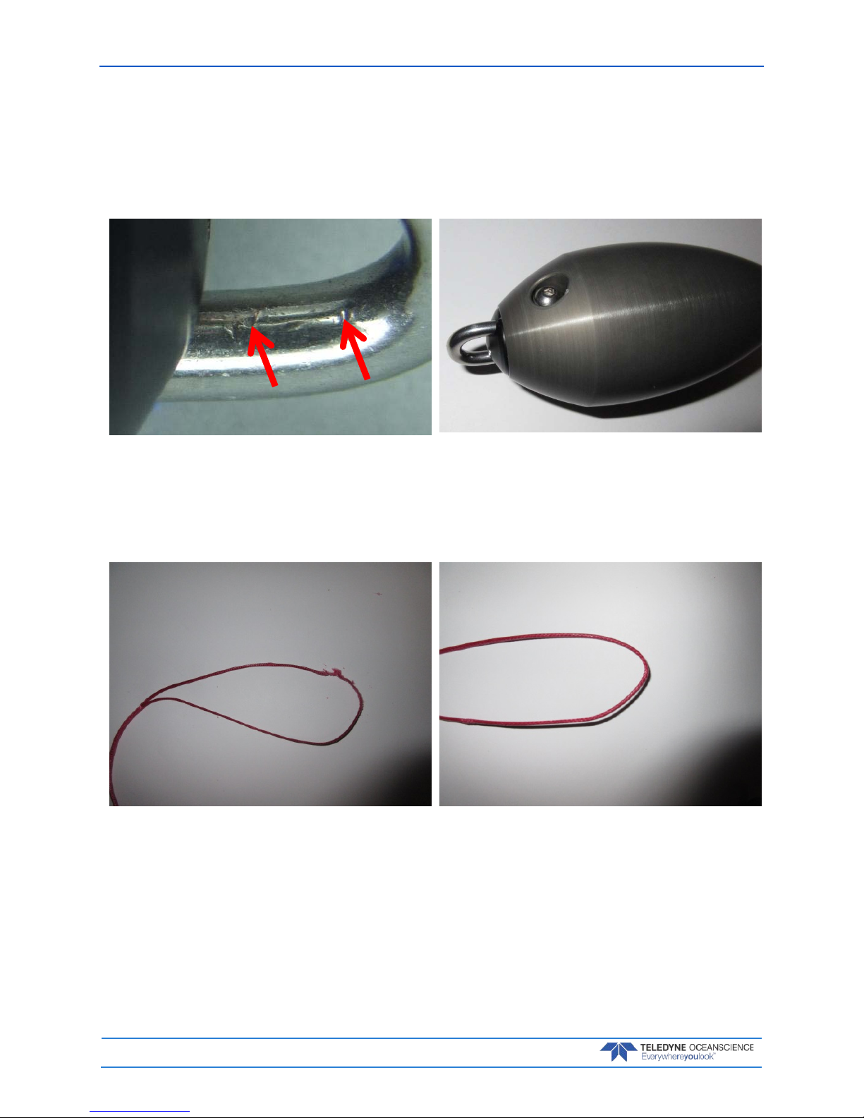
March 2018 rapidCAST User’s Guide
Page 76
EAR-Controlled Technology Subject to Restrictions Contained on the Cover Page.
Tailspool
• Inspect the shackle and loop splice every time the probe is onboard and before it goes overboard.
• The shackle should be shiny and have no burrs. If the shackle has any burrs or damage, replace it
IMMEDIATELY.
Figure 40. Bad shackle
Arrows show damage from removal with hard tool.
Figure 41. Good Shackle
• The loop splice should be intact and uncut. There is a risk of losing the probe if the splice starts to
walk out.
Figure 42. Bad Loop splice, worn and torn Figure 43. Good Loop Splice
Page 83

rapidCAST User’s Guide March 2018
EAR-Controlled Technology Subject to Restrictions Contained on the Cover Page.
Page 77
• The inline splice should be intact and not walking out. There is a high risk of losing the probe if
the splice starts to walk out. The inline splice is only held by friction and is strongest when loaded.
Figure 44. BAD Inline Splice
Note how it is starting to walk out. Re-tighten or replace.
Figure 45. Good Inline Splice
Page 84

March 2018 rapidCAST User’s Guide
Page 78
EAR-Controlled Technology Subject to Restrictions Contained on the Cover Page.
Shackle Replacement
ONLY USE ROPE TO THE REMOVE SHACKLE. Use of hard tools will create burrs and render the
shackle useless.
To replace the shackle:
1. Loosen and then remove the bolt and flat washer.
2. Using a small length of rope, pull the shackle free.
3. Look for signs of corrosion such as white deposits. If corrosion caused part of the probe to be visibly damaged, do not redeploy your system. Send it back to Oceanscience for inspection.
4. Push in the new shackle.
5. Brush the screw with marine environment grease such as AquaShield
®
. This is used to prevent
corrosion in the threads of the aluminum body. Use gloves as the grease tends to stick to your
skin. Note that the grease is incompressible and therefore apply a thin layer to the screw to avoid
binding or difficulty in the installation of the screw in the mounting hole. Insert the flat washer
and bolt and tighten.
Figure 46. Shackle Replacement
81J-6000-00
Page 85

rapidCAST User’s Guide March 2018
EAR-Controlled Technology Subject to Restrictions Contained on the Cover Page.
Page 79
Loop Splice
During intensive surveys, the probe loop splice should be replaced daily by cutting 50cm of line from the
end and re-splicing the termination. This will take just a few minutes. The entire line section should be
replaced after 1000 casts as a preventative measure.
Figure 47. Loop Splice
Graphic courtesy of Innovative Textiles, Inc.
Page 86

March 2018 rapidCAST User’s Guide
Page 80
EAR-Controlled Technology Subject to Restrictions Contained on the Cover Page.
Inline Splice
There are two inline splices between the red and white lines. On most systems, the first 200 meters of line
is red. The next 1500 meters of line is white. The remaining 100 meters of line is red. Inspect and if
needed, follow the hollow core braid splice instructions as shown below.
Figure 48. Inline Splice
Graphic courtesy of Innovative Textiles, Inc.
Replacing the Spool
This procedure shows how to replace a spool in the rapidCAST.
Removing the Spool
1. Position rapidCAST such that the rear of the unit can be accessed (Davit arm is extending away).
2. Using appropriate tools remove the four screws and washers holding the top cover of rapidCAST.
3. Set the cover aside being careful to not lose the hardware (screws and washers).
4. Remove the right side cover as viewed from the rear. Set aside.
Page 87
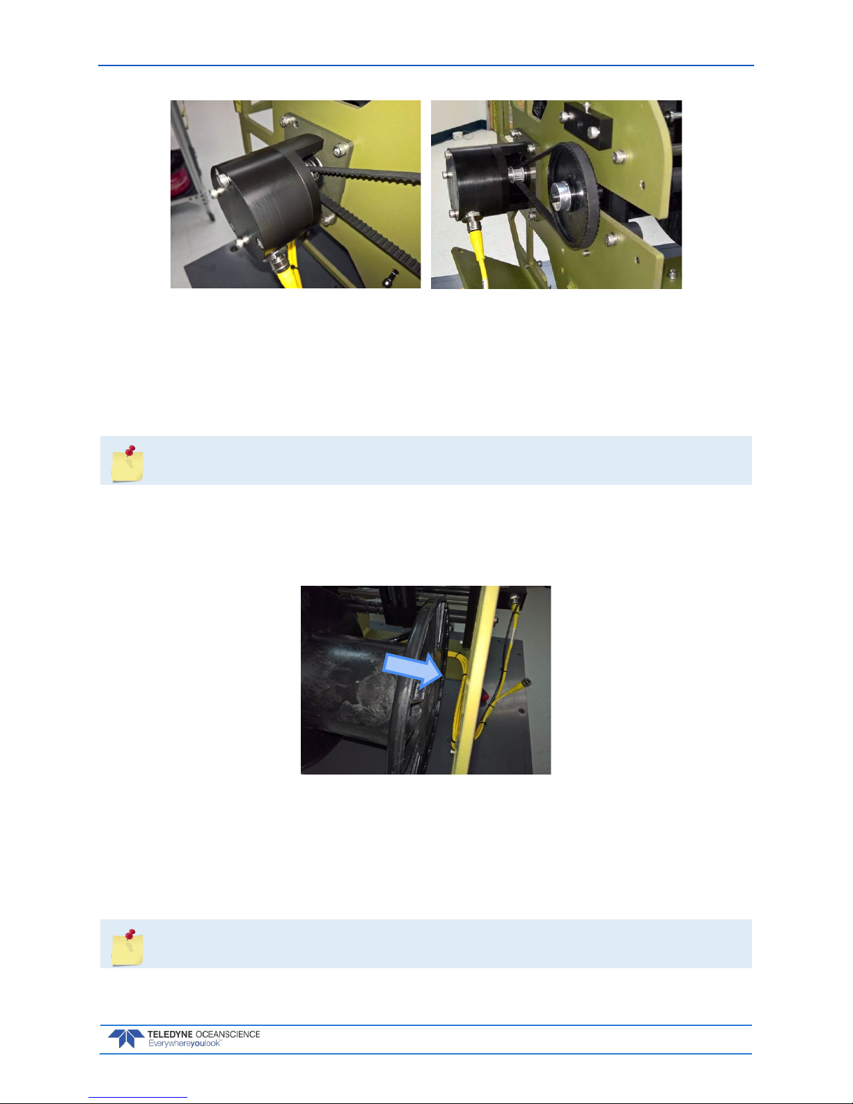
rapidCAST User’s Guide March 2018
EAR-Controlled Technology Subject to Restrictions Contained on the Cover Page.
Page 81
Figure 49. Removing the Encoder
5. Pulling gently on the grip ring, carefully remove the Encoder cable from bottom of the encoder
assembly. Allow the cable to dangle in place.
6. Loosen the four bolts holding Encoder assembly to the chassis.
7. Remove the encoder belt from the larger front gear (to the level-wind).
8. Remove the loosened screws and washers on the Encoder and set aside.
Make sure that spool is supported but does not extract with the following step. It is heavy
and can cause damage if dropped.
9. Carefully slide the encoder assembly to the right, away from the chassis. Do not remove the spool
yet. Set the encoder aside.
10. While supporting the weight of the spool, carefully slide it to the right off the motor axle.
11. Lower the spool through the bottom of the chassis.
Figure 50. Removing the Spool
Reassembling the Spool Module
1. Position the spool such that the strengthening bar is to the left of the rapidCAST as viewed from
the rear (Davit pointing away).
2. The line should now be positioned to unspool from the top.
If the line is not in this orientation then do not use this spool until it is corrected!
Page 88

March 2018 rapidCAST User’s Guide
Page 82
EAR-Controlled Technology Subject to Restrictions Contained on the Cover Page.
3. Lift the spool from the bottom of the chassis and position the square hole in the strengthener onto
the motor axle.
Figure 51. Spool Retention Points
4. Position the encoder assembly so that the square axle aligns with the hole in the plastic side of the
spool.
5. When the encoder is in place, then support the spool while installing the four mounting bolts and
washers that you removed earlier to finger tight, but not torqued.
6. Slide the belt onto the front gear. Ensure that it rides on the back gear centered.
The front gear may be offset up to 50% width of the belt and still maintain proper operation.
There is very little force on it and it will vary from spool to spool due to machine tolerances.
7. Tighten the four bolts to 35 in-lbs (4N.m).
8. At the bottom of the encoder assembly reposition and install the Spool cable ensuring the grip
ring clips into place.
9. Verify proper operation of the spool and belt before installing the right and top covers using hardware that was removed earlier.
10. Tighten all M6 hardware to 35 in-lbs (4N.m).
Figure 52. Spool Installed
Motor
Encoder
Page 89

rapidCAST User’s Guide March 2018
EAR-Controlled Technology Subject to Restrictions Contained on the Cover Page.
Page 83
Appendix A - Installation Drawings
Page 90
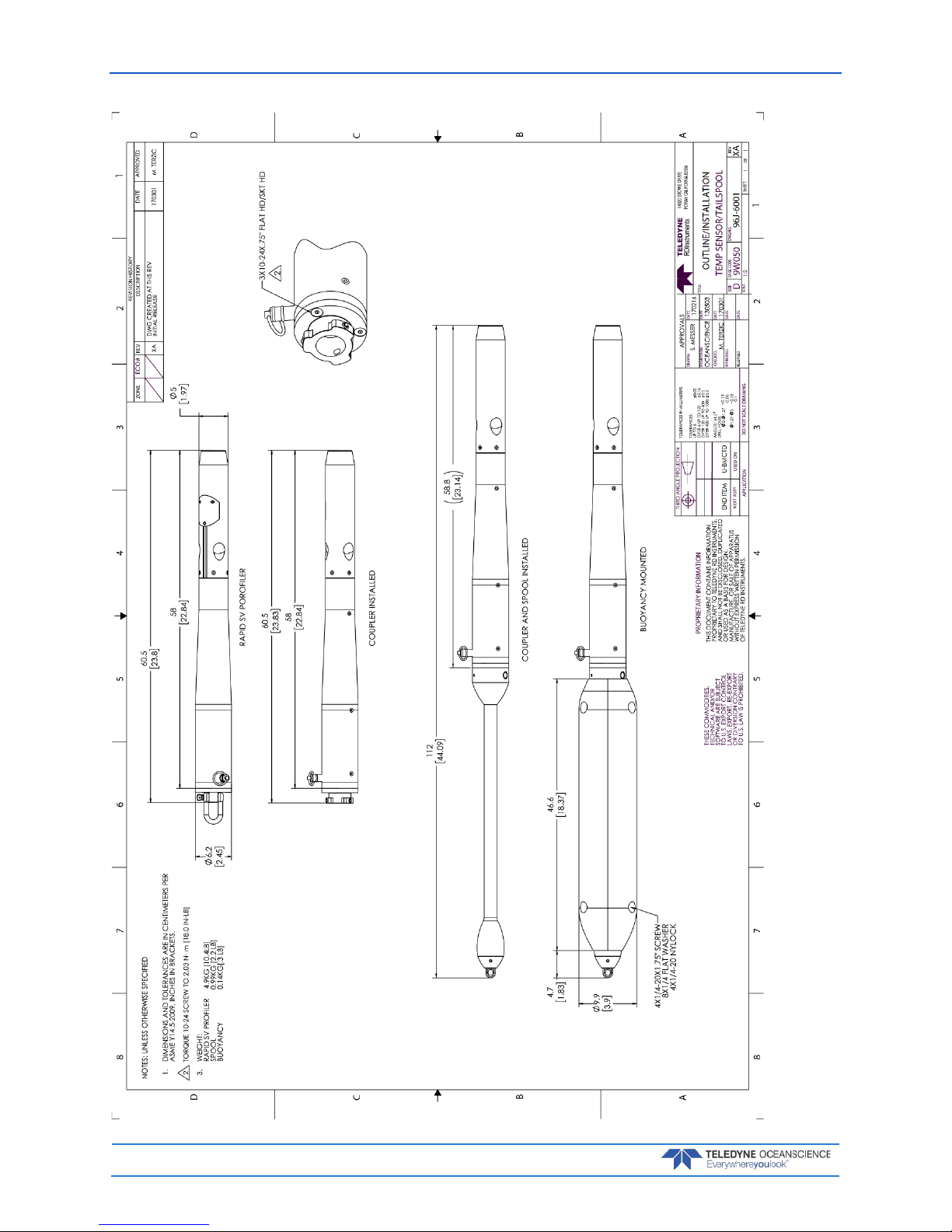
March 2018 rapidCAST User’s Guide
Page 84
EAR-Controlled Technology Subject to Restrictions Contained on the Cover Page.
Page 91

rapidCAST User’s Guide March 2018
EAR-Controlled Technology Subject to Restrictions Contained on the Cover Page.
Page 85
Page 92

March 2018 rapidCAST User’s Guide
Page 86
EAR-Controlled Technology Subject to Restrictions Contained on the Cover Page.
Page 93

rapidCAST User’s Guide March 2018
EAR-Controlled Technology Subject to Restrictions Contained on the Cover Page.
Page 87
Page 94

March 2018 rapidCAST User’s Guide
Page 88
EAR-Controlled Technology Subject to Restrictions Contained on the Cover Page.
Page 95

rapidCAST User’s Guide March 2018
EAR-Controlled Technology Subject to Restrictions Contained on the Cover Page.
Page 89
NOTES
 Loading...