

Page 1

T3DMM4-5 / T3DMM5-5 / T3DMM6-5
4½, 5½ and 6½ Digit Digital Multimeters
Quick Start Guide
Version 1.1
September, 2018
Find Quality Products Online at: sales@GlobalTestSupply.com
www.GlobalTestSupply.com
Page 2

Contents
General Safety Summary.............................................................. 1
Daily Maintenance and Cleaning.................................................. 7
General Inspection........................................................................ 8
Dimensions.................................................................................... 9
Handle Adjustment.......................................................................10
Front Panel ...................................................................................11
Rear Panel.....................................................................................14
Starting the Multimeter ............................................................... 17
User Interface............................................................................... 18
Measurement Connections ......................................................... 19
Connecting to USB and LAN Ports............................................ 22
Using the Built-in Help System...................................................23
Troubleshooting.......................................................................... 24
© 2018 Teledyne LeCroy, Inc. All rights reserved.
Teledyne Test Tools is a brand and trademark of Teledyne LeCroy, Inc.
Other product or brand names are trademarks or requested trademarks
of their respective holders. Specifications, prices, availability and
delivery subject to change without notice.
Find Quality Products Online at: sales@GlobalTestSupply.com
www.GlobalTestSupply.com
Page 3

General Safety Summary
Read the following precautions carefully to avoid any personal
injuries, or damage to the instrument or products connected to it.
Use the instrument only as specified.
Use only the power cord supplied for the instrument.
Ground the instrument. The instrument is grounded through the
ground conductor of the power cord. To avoid electric shock,
always connect to grounded outlets. Make sure the instrument is
grounded correctly before connecting its input or output terminals.
Connect the signal wire correctly. To avoid damage, observe
input polarity and maximum voltage/current ratings at all times.
Observe all terminal ratings and signs on the instrument to
avoid fire or electric shock. Before connecting to the instrument,
read the manual to understand the input/output ratings.
Do not operate with suspected failures. If you suspect that the
instrument is damaged, contact the Teledyne LeCroy service
department immediately.
Do not operate in wet/damp conditions.
Do not operate in an explosive atmosphere.
Keep the surface of the instrument clean and dry.
Avoid touching exposed circuits or wires. Do not touch
exposed contacts or components when the power is on.
Do not operate without covers. Do not operate the instrument
with covers or panels removed.
Use only the fuse specified for the instrument.
Use proper overvoltage protection.
Use anti-static protection. Operate in an anti-static protected
area. Ground measurement cable conductors before connecting
to the instrument to discharge any static electricity before
connecting the cables to the instrument.
Observe ventilation requirements. Ensure good ventilation.
Check the vent and fan regularly to prevent overheating.
Find Quality Products Online at: sales@GlobalTestSupply.com
www.GlobalTestSupply.com
Quick Start 1
Page 4

2 Quick Start
Safety Terms and Symbols
The following terms may appear on the instrument:
DANGER:
Direct injury or hazard may occur.
WARNING:
Potential injury or hazard may occur.
CAUTION:
Potential damage to instrument/property may occur.
CAT I
(1): IEC Measurement Category I, applicable for making
measurements on ‘other’ circuits that are not directly connected to
mains. See p. 6.
CAT II:
IEC Measurement Category II, applicable for making
measurements on circuits connected directly to utilization points
(socket outlets and similar points) of the low voltage mains installation.
See p. 5.
(1) CAT I as defined in IEC/EN 61010-031:2008. Note that
Measurement Category I was removed in IEC/EN 61010-031:2015
and replaced by ‘O’, indicating "other circuits that are not directly
connected to mains."
The following symbols may appear on the instrument:
CAUTION
Risk of
injury or
damage.
Refer to
manual.
WARNING
Risk of
electric
shock or
burn
Earth
Ground
Terminal
Protective
Conductor
Terminal
Frame or
Chassis
Terminal
ON/
Standby
Power
Alternating
Current
Find Quality Products Online at: sales@GlobalTestSupply.com
www.GlobalTestSupply.com
Page 5

Operating Environment
Temperature: 0 °C to 40 °C
Humidity: 5% to 90% relative humidity (non-condensing) up to
+30 °C. Upper limit derates to 50% relative humidity (non-
condensing) at +40 °C.
Altitude: ≤ 2000 m
Use indoors only.
Pollution Degree 2. Use in an operating environment where
normally only dry, non-conductive pollution occurs. Temporary
conductivity caused by condensation should be expected.
AC Power
Input Voltage & Frequency: 100-120 V at 50/60 Hz
or 200-240 V at 50/60 Hz
Manual AC selection with a slide switch.
Power Consumption: 20 W maximum
Mains Supply Connector: CAT II per IEC/EN 61010-1:2010,
instrument intended to be supplied from the building wiring at
utilization points (socket outlets and similar).
Fuse Type
Current Input Terminal: 250 VAC F 10 A, 3 AG
AC Mains: 250 VAC F 300 mA, 5x20 mm
Find Quality Products Online at: sales@GlobalTestSupply.com
www.GlobalTestSupply.com
Quick Start 3
Page 6

4 Quick Start
Input Terminal Protection Limitation
Protection limitation is defined for the input terminal.
1. Main Input (HI and LO) Terminals
HI and LO terminals are used for Voltage, Resistance,
Capacitance, Continuity, Frequency, Diode and Temperature
measurement. Two protection limitations are defined:
HI-LO protection limitation: 1000 VDC or 750 VAC. This is
the maximum measurable voltage. The limitation can be
expressed as 1000 Vpk.
LO ground protection limitation: LO terminal can “float” 500
Vpk relative to the ground safely. The maximum protection
limitation of HI terminal relative to the ground is 1000 Vpk.
Therefore, the sum of the “float” voltage and the measured
voltage can’t exceed 1000 Vpk.
2. Sampling (HISense and LOSense) Terminals
HISense and LOSense terminals are used for 4-wire Resistance
measurement. Two protection limitations are defined:
HISense-LOSense protection limitation: 2000 Vpk.
LOSense-LOSense protection limitation: 2 Vpk.
3. Current Input (I) Terminal
The I terminal is used for current measurement. The
maximum current which can go through the I terminal is
limited to 10 A by the fuse on the back panel.
NOTE:
Voltage on the current input terminal corresponds to voltage on
the LO terminal. To keep good protection, only use a fuse of the
specified type and value to replace this fuse.
Find Quality Products Online at: sales@GlobalTestSupply.com
www.GlobalTestSupply.com
Page 7

IEC Measurement Category II Overvoltage Protection
To avoid the danger of electric shock, the Digital Multimeter
provides overvoltage protection for line-voltage mains
connections that meet both of the following conditions:
1. The HI and LO input terminals are connected to the mains
under Measurement Category
II conditions described in the
warning below.
2. The maximum line voltage of the mains does not exceed:
300 VAC for T3DMM4-5
600 VAC for T3DMM5-5 and T3DMM6-5
WARNING:
IEC Measurement Category II includes electrical devices
connected to mains at an outlet on a branch circuit, such as most
small appliances, test equipments, and other devices that
plug into a branch outlet or socket.
The multimeter is capable of making measurements with the HI
and LO inputs connected to mains in such devices (≤ 300 VAC
for T3DMM4-5 and ≤ 600 VAC for T3DMM5-5/T3DMM6-5) or to
the branch outlet itself.
However, the HI and LO terminals of the multimeter can’t be
connected to mains in permanently installed electrical devices
such as the main circuit-breaker panels, sub-panel disconnected
boxes and permanently wired motors. Such devices and circuits
are prone to exceed the protection limits of the multimeter.
Find Quality Products Online at: sales@GlobalTestSupply.com
www.GlobalTestSupply.com
Quick Start 5
Page 8

6 Quick Start
Limits for Measurements on Other Circuits
Not Directly Connected to Mains
Max. rated input voltage: 1000 Vrms
Transient overvoltage: 4000 Vpk
WARNING:
Voltages above 300 VAC (for T3DMM4-5) or 600 VAC
(T3DMM5-5 / T3DMM6-5) can only be measured in circuits that
are isolated from mains. However, there may be transient over
voltage in circuits that are isolated from mains. The multimeter is
able to withstand occasional transient overvoltage up to 4000 Vpk.
Please don’t use this instrument to measure circuits where
transient overvoltage may exceed this level.
Find Quality Products Online at: sales@GlobalTestSupply.com
www.GlobalTestSupply.com
Page 9

Daily Maintenance and Cleaning
Maintenance
Protect the liquid crystal display from direct sunlight when
storing or using the instrument.
NOTE:
To avoid damage to the instrument or test leads, please don’t
place them in mist, liquid or solvent.
Cleaning
Regularly clean the instrument and test leads.
● Wipe the external dust off the instrument and test leads using a
soft rag. Be careful not to scratch the display screen when
cleaning. Do not allow any liquid to enter the instrument.
● Use a damp soft rag to clean the instrument after removing the
power plug. Or use 75% isopropyl alcohol / water solvent to get
a more thorough cleaning.
NOTE:
To prevent the surface of the instrument or test leads from
damage, please don’t use any corrosive or chemical cleaning
reagents.
Please make sure the instrument is fully dry before
reconnecting the power to avoid short circuits or personal injury.
Quick Start 7
Find Quality Products Online at: sales@GlobalTestSupply.com
www.GlobalTestSupply.com
Page 10

Please check the instrument according to the following steps.
1. Inspect the shipping container.
Keep the shipping container and packaging material until the
contents of the shipment have been completely checked and the
instrument has passed both electrical and mechanical tests. It is
always good practice to save the shipping container and packaging
for use when returning the power supply to Teledyne LeCroy for
service or calibration.
The consigner or carrier will be responsible for damage to the
instrument resulting from shipping. Teledyne LeCroy will not
provide free maintenance or replacement in this instance.
2. Inspect the instrument.
If the instrument is found to be damaged, defective or fails in
electrical or mechanical tests, please contact the Teledyne LeCroy
service department immediately.
3. Check the accessories.
Please check that you have received the accessories on the
packing list. If the accessories are incomplete or damaged, please
contact Teledyne LeCroy immediately.
General Inspection
8 Quick Start
Find Quality Products Online at: sales@GlobalTestSupply.com
www.GlobalTestSupply.com
Page 11

Dimensions
260.27mm
107.21 mm
T3DMM4-5: 293.75mm
T3DMM5-5: 293.75mm
T3DMM6-5: 345.45mm
Quick Start 9
Find Quality Products Online at: sales@GlobalTestSupply.com
www.GlobalTestSupply.com
Page 12

Handle Adjustment
To adjust the handle position of the Multimeter, grip the handle by
the two sides and pull outward. Then, rotate the handle to the
appropriate position.
Handle Adjustment
Carrying Position
Horizontal Position
10 Quick Start
Find Quality Products Online at: sales@GlobalTestSupply.com
www.GlobalTestSupply.com
Page 13

Front Panel
Front Panel Overview
USB Host
Users can store the current state or measurement data into a
USB storage device. Users can also read the state files or
updated firmware from a USB storage device.
Power Key
Turn the instrument on or off.
LCD Display
The instrument provides a 4.3 inch high resolution color TFT-LCD
display screen with 480*272 pixels that displays the function
menus, measurement parameter settings, system status, and
prompt messages.
Menu Operation Keys
Press any softkey to activate the corresponding menu.
C
D
A
B
B
A
C
D
E
F
G
Quick Start 11
Find Quality Products Online at: sales@GlobalTestSupply.com
www.GlobalTestSupply.com
Page 14

DC Voltage / Current Measurement
AC Voltage / Current Measurement
2-Wire / 4-Wire Resistance Measurement
Frequency / Capacitance Measurement
Continuity / Diode Test
Temperature Measurement / Enable
Multiple Scan Card Function
Enable Dual-display Function / Set Up the Utility
Acquire Function / Help System
Math Function / Display Function
Auto Trigger / Stop
Single Trigger / Hold Measurement Function
Return to local control of the instrument (when in
Remote mode).
Some of the front panel keys have text above them.
This indicates that the key has a function that you
can access by pressing and releasing [Shift] before
pressing the key.
Measurement and Assistant Function Keys
E
12 Quick Start
Find Quality Products Online at: sales@GlobalTestSupply.com
www.GlobalTestSupply.com
Page 15

Range and Direction Keys
Increase the measurement range
Decrease the measurement range
Select auto or manual range
Set up measurement parameter
Move the cursor
Page up or down
Set up measurement parameter
Move the cursor
Apply the current setting
Signal Input Terminals
The measured signal (device) will be connected into the
multimeter through these terminals. Different measurement
objects have different connection methods. For details, please
refer to “Measurement Connections”.
G
F
Quick Start 13
Find Quality Products Online at: sales@GlobalTestSupply.com
www.GlobalTestSupply.com
Page 16

Rear Panel
Rear Panel Overview
Power Socket
The multimeter accepts two types of AC supplies. Please use
the power cord provided in the accessories to connect the
multimeter to the AC power through this socket.
Note: The correct voltage scale must be first selected (through the
Voltage Selector) before power connection.
Power Fuse
The multimeter is already installed with a power fuse before
leaving factory. To change the fuse please:
1) Turn off the multimeter and remove the power cord.
2) Press down the block tongue using a straight screwdriver
(in the direction of the dotted arrow in the figure below)
and pull out of the fuse seat.
3) Select a proper voltage scale.
4) Replace a specified fuse.
5) Reinstall the fuse seat into the slot.
I
G
H
F
E
A
B
C
D
A
B
J
!
14 Quick Start
Find Quality Products Online at: sales@GlobalTestSupply.com
www.GlobalTestSupply.com
Page 17

Changing the fuse
AC Voltage Selector
Select the correct voltage scale (110 V or 220 V) for the
AC supply used.
Inspection card (option)
An optional 16-channel Data Acquisition Module can be
installed in the instrument.
USB Device
Connect the PC through this interface. You can use SCPI
commands or PC software to control the Multimeter remotely.
LAN
Through this interface, the multimeter can be connected to
the network for remote control.
VMC Output
The mutlimeter outputs a low-true pulse from the [VM Comp]
connector after every measurement
E
G
F
D
C
!
Quick Start 15
Find Quality Products Online at: sales@GlobalTestSupply.com
www.GlobalTestSupply.com
Page 18

Ext Trigger
Trigger the multimeter by connecting a trigger pulse through
the [Ext Trig] connector. Note the external trigger source must
be selected.
Current Input Fuse
The multimeter is already installed with a current Input fuse
to provide 10 A maximum input protection before leaving
factory. To replace a new one, please:
1) Turn off the multimeter and remove the power cord.
2) Turn the fuse seat counterclockwise as shown in the
figure using a straight screw driver and then pull out the
fuse seat
3) Place a new 10 A specified fuse.
4) Reinstall the fuse seat into the slot.
Instrument Kensington Lock Point
A Kensington lock (not supplied) can be used to lock the
multimeter to a fixed place if necessary.
I
H
J
16 Quick Start
Find Quality Products Online at: sales@GlobalTestSupply.com
www.GlobalTestSupply.com
Page 19

Starting the Multimeter
Before connecting the instrument to a power
source please adjust the AC voltage selector on the
rear panel of your multimeter according to your local
power supply voltage. Then connect the power cord as
shown in the following figure.
Connecting the Power Cord
Press the Power key on the front panel to turn on the multimeter.
If the multimeter does not start normally, then try the following:
1. Make sure the power cord is in good connection and connected
to the multimeter and the wall socket.
2. Ensure that the wall socket has power and is turned on.
3. Try to restart the multimeter, if it fails, check the power fuse and
replace with a new one if necessary.
4. If the problem still remains, please contact the Teledyne LeCroy
service department for help.
!
Quick Start 17
Find Quality Products Online at: sales@GlobalTestSupply.com
www.GlobalTestSupply.com
Page 20

User Interface
Measurement
Function
Measuremet
Result
Trigger Mode
LAN Status Icon
Control Mode
Range
Operation Menu
User Interface Display
18 Quick Start
Find Quality Products Online at: sales@GlobalTestSupply.com
www.GlobalTestSupply.com
Page 21
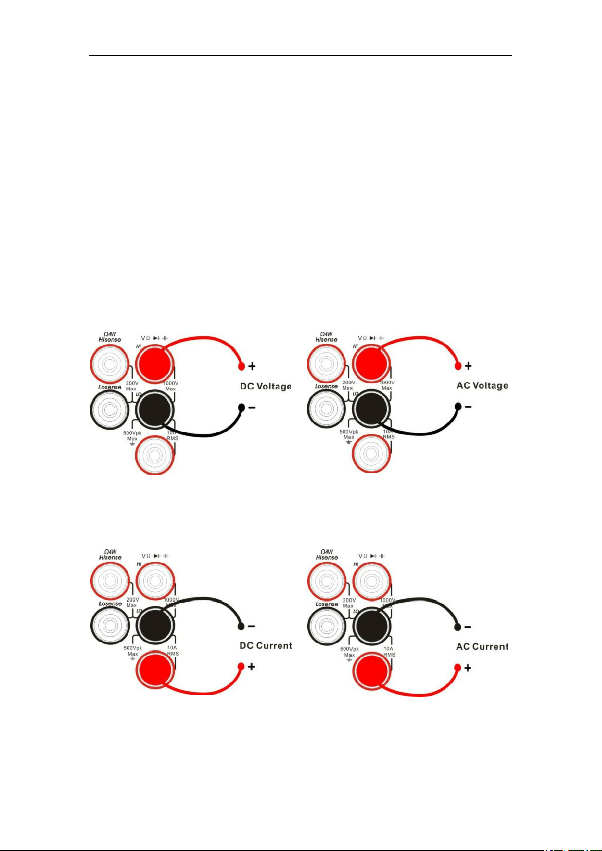
Measurement Connections
The Digital Multimeter is designed with many measurement
functions. After selecting the desired measurement function, please
connect the signal (device) under test to the multimeter according to
the method below. Do not switch the measurement function
when measuring as it may cause damage to the multimeter.
For example, when the test leads are connected to the related
current terminals, AC voltage measurement should not be used.
DCV Measurement ACV Measurement
DCI Measurement ACI Measurement
Quick Start 19
Find Quality Products Online at: sales@GlobalTestSupply.com
www.GlobalTestSupply.com
Page 22

Resistance Measurement (2-wire) Resistance Measurement (4-wire)
Capacitance Measurement
Continuity Measurement Frequency/Period Measurement
Connect the test leads and tested
circuit as in the diagram below.
The HI terminal and HI Sense
should be connected to one end
of the DUT. The LO terminal and
LO Sense should be connected to
the other end of the DUT.
20 Quick Start
Find Quality Products Online at: sales@GlobalTestSupply.com
www.GlobalTestSupply.com
Page 23

Temperature Measurement
( For RTD and thermcouple sensors)
Diode Measurement
Quick Start 21
Find Quality Products Online at: sales@GlobalTestSupply.com
www.GlobalTestSupply.com
Page 24

Connecting to USB and LAN Ports
The Digital Multimeter has LAN and USB I/O ports. Connect to
the ports as in the diagrams below:
Connect to LAN
Connect to USB Device Port
Connect to USB Host Port
Find Quality Products Online at: sales@GlobalTestSupply.com
22 Quick Start
www.GlobalTestSupply.com
Page 25

Using the Built-in Help System
To access the built-in help system, press [Shift] + [Acquire],
then use the direction keys to choose the help item you want.
Finally, press [ O K ] to obtain help.
The help listings are as follows:
1. Basic Measurements
2. Measuring Temperature
3. Measuring Capacitance
4. Math Function
5. Dual-display Function
6. Saving and Recalling Information
7. Optional Multiple Scan Card
8. The convention and Tips for Softkeys
Quick Start 23
Find Quality Products Online at: sales@GlobalTestSupply.com
www.GlobalTestSupply.com
Page 26

Troubleshooting
The commonly encountered failures and their solutions are listed
below. When you encounter those problems, please resolve them
using the following steps. If the problem remains, please contact the
Teledyne LeCroy service centre and provide your device Information
including serial number.
The screen has no display after pressing the power
key.
1. Check whether the power cord is fully connected.
2. Check whether the power fuse has blown or has failed. If the
fuse needs to be changed, please use the specified fuse.
3. Restart the instrument after finishing the above checks.
4. If the instrument still doesn’t start up properly, please contact
the Teledyne LeCroy service center.
The reading doesn’t change when a current signal is input.
1. Check whether the test lead is correctly inserted into the HI
and LO terminals of current measurement.
2. Check whether the current fuse at the back panel has blown.
3. Check whether the DCI or ACI measurement function is
enabled.
4. Check whether the DCI measurement function is used to
measure AC current.
24 Quick Start
Find Quality Products Online at: sales@GlobalTestSupply.com
www.GlobalTestSupply.com
Page 27

The reading is abnormal when a voltage signal is input.
1. Check whether the test lead is correctly inserted into the HI
and LO terminals for voltage measurements.
2. Check whether the the DCV or ACV measurement function is
enabled.
3. Check whether the DCV measurement function is used to
measure AC voltage.
The USB storage device cannot be identified.
1. Check whether the USB storage device is in good condition.
2. Make sure the USB storage device you used is a flash
storage device. This instrument does not support hardware
storage types.
3. Check the capacity of your USB storage device. It is
recommended that the capacity of the USB storage device is
no larger than 8G bytes and FAT formatted.
4. Restart the instrument, then insert the USB storage
device.
5. If the problem persists, please contact the Teledyne LeCroy
service centre.
Quick Start 25
Find Quality Products Online at: sales@GlobalTestSupply.com
www.GlobalTestSupply.com
Page 28

ABOUT TELEDYNE TEST TOOLS
Company Profile
Teledyne LeCroy is a leading provider of oscilloscopes, protocol analyzers and related test and measurement
solutions that enable companies across a wide range of industries to design and test electronic devices of all types.
Since our founding in 1964, we have focused on creating products that improve productivity by helping engineers
resolve design issues faster and more effectively. Oscilloscopes are tools used by designers and engineers to
measure and analyze complex electronic signals in order to develop high-performance systems and to validate
electronic designs in order to improve time to market.
The Teledyne Test Tools brand expands on the Teledyne LeCroy product portfolio by adding a comprehensive range
of test equipment solutions for its customers. The new range of product solutions deliver engineers with a broad
range of quality test solutions that enables speed to market product validation and design. More and more
designers, engineers and lecturers are relying on Teledyne Test Tools to meet their testing, education and
electronics validation needs with confidence and within budget.
Location and Facilities
Headquartered in Chestnut Ridge, New York, Teledyne Test Tools and Teldyne LeCroy have sales, service and
development subsidiaries in the US and throughout Europe and Asia. Teledyne Test Tools and LeCroy products are
employed across a wide variety of industries, including semiconductor, computer, consumer electronics, education,
military/aerospace, automotive/industrial, and telecommunications.
930339-00 RevA
Find Quality Products Online at: sales@GlobalTestSupply.com
www.GlobalTestSupply.com
 Loading...