

Page 1
SierraNet™ M328
Quick Start
Before Starting
Use this document for quick installation and setup. If you
experience problems or need more information, see the
Net Protocol Suite User Manual on the Installation DVD-ROM or
at the Teledyne LeCroy web site. For details about the latest
software version, see the Readme file on the
Installation DVD-ROM.
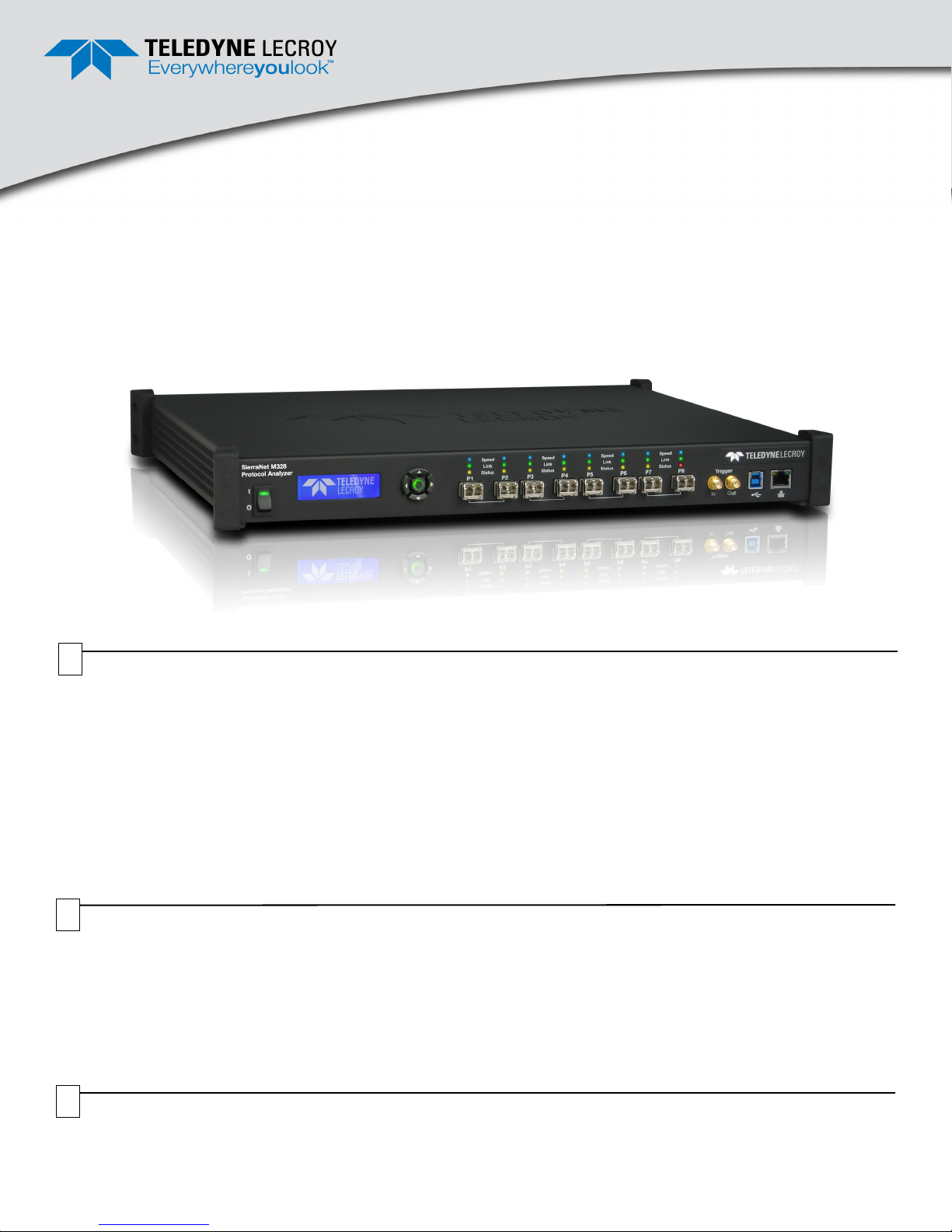
SierraNet M328 Protocol Analyzer
1
Introduction
The SierraNet M328 analyzer is Teledyne LeCroy's
25/50/100 Gigabit Ethernet and Gen6 Fibre Channel
Analyzer/Jammer platform. It has eight SFP+ ports. Up to
128 GB of capture memory allows for capturing of
extensive line-speed data. The analyzer can be controlled
either via a one (1) Gigabit Ethernet connection to the local
network or via a USB connection.
The SierraNet M328 provides the user with
easy-to-understand control panel and LED indicators.
Major features of the M328 include triggering on
2
Components
The analyzer package includes the following components:
SierraNet M328 Analysis platform
USB 3.0 cable, 1 meter
USB 2.0 cable, 1.8 meter
1 Gigabit Ethernet cable, 10 feet
2 QSFP-4XSFP fanout 1M copper cables
Please see the Net Protocol Suite User Manual on the installation DVD-ROM for component specifications and further details.
back-to-back events, use of counters within trigger
conditions, and multi-state (up to 24) triggering and filtering
state machines with four transitions per state and FlexPort,
which allows concurrent Ethernet and FC analysis.
The Net Protocol Suite
analyzer and displaying the captured data installs on the
latest Microsoft
for the latest information on host-machine requirements.
DB9 to DB9 Sync cable, 6 feet
Three prong AC power cord
C13-C14 10A power cord, 2 meter
DVD-ROM with software and documentation
This Quick Start guide
®
™
Windows
software for controlling the
®
version. See the Readme file
3
Unpacking the Analyzer
Inspect the received shipping container for any damage.
Unpack the container and account for each of the system
components listed on the accompanying packing list.
Visually inspect each component for absence of damage.
In the event of damage, notify the shipper and Teledyne
LeCroy. Retain all shipping materials for shipper’s
inspection.
Page 2

23 78
1
9
1056
11 141111
11
12
4
Front Panel Description
Features
The Analyzer has the following features on the front:
[1] LED Indicators for P1- P8 for Speed, Link and Status
[2] Power Switch
[3] Status and Configuration LCD Display
[4] Front Panel 5-Buttons keypad
[5] SFP+ 25 GigE / FC Gen6 connectors for ports 1-2
[6] SFP+ 25 GigE / FC Gen6 connectors for ports 3-4
[7] SFP+ 25 GigE / FC Gen6 connectors for ports 5-6
[8] SFP+ 25 GigE / FC Gen6 connectors for ports 7-8
[9] External Trigger Input (Trigger In)
[10] External Trigger Output (Trigger Out)
[11] USB Port for host connectivity
[12] Ethernet Port for network connectivity
Please see the Net Protocol Suite User Manual for details
on the LEDs.
Speed LEDs
Ethernet Fibre Channel
Yellow Reserved 8G/4G/2G/1G FC
Green 10/40 GigE 16G FC
Blue
Link Activity LEDs
Green Network activity Detected
Yellow Link up, no activity
No Color No link
Status LEDs
Yellow Blinking Waiting for trigger
Yellow Solid Triggered
Red Error detected
No Color No Activity
25/100 GigE 32/128G FC
5
Front Panel Buttons
The following parameters can be viewed and/or configured directly on the front panel, using the display and 5 button keypad:
- Display of IP address
- Display of model name: “SierraNet M328”
- Connection status
- Display of unit name
6
Rear Panel Description
The back of the SierraNet M328 system has SYNC OUT
and SYNC IN connectors that can be used to daisy-chain
multiple analysis systems.
Note: Do not open the enclosure. No user serviceable parts
are inside.
7
Installing the Software
1. Insert the Installation DVD-ROM into the DVD drive on
the host machine. The installation automatically starts
setup, unless Auto Run is off. In that case, select the
DVD-ROM from “My Computer” and click Setup.
Follow the instructions to complete the installation.
- IP configuration
• IP mode dynamic, or
• IP mode static
2. Restart the computer before using the software.
Note: If you get an error message during installation of the
drivers, consult your system administrator.
Page 3

8
Setting Up and Connecting
Note: You must install the Net Protocol Suite software
(
Section “7” on page ii) before connecting the analyzer to the
host machine for the first time.
To set up the analyzer:
1. Connect the Ethernet cable between the
SierraNet M328 Analyzer’s Ethernet Port and an
Ethernet Port on the host machine, an Ethernet switch
or Gigabit Ethernet interface. Alternatively, connect a
USB cable from the USB port on the analyzer to the
host machine. After the analyzer is turned on, the host
machine will detect the analyzer and load the driver
files.
9
Connecting the Analyzer to the Application
2. Connect the analyzer to a 100V–240V, 50Hz–60Hz,
power outlet and turn on the Power switch. At power
on, the analyzer will go through initialization as shown
on the LCD display.
3. Connect your devices under test using either optical
modules and fibre cables or appropriate copper
cabling, suitable for your configuration.
4. Connect your devices under test to port pairs P1/P2,
P3/P4, P5/P6 and/or P7/P8.
For an illustration of the cabling, see the Introduction
chapter of the Net Protocol Suite User Manual.
To launch the analyzer’s application software, select Start
> All Programs > LeCroy > Net Protocol Suite.
Select Menu > Setup > Device Management (see screen
capture below) to display the Device Management dialog.
Connecting via USB
The application automatically detects USB-connected
analyzers. No further setup actions are needed.
Connecting via Ethernet
To connect to the network, the SierraNet M328 must be
assigned an IP address. Typically, the IP address will be
assigned automatically, if the network has a DHCP server.
Same Subnets
Once the IP Address is assigned, the SierraNet M328
analyzer is automatically detected by the application if the
analyzer and the host machine are on the same subnet.
Different Subnets
If the analyzer and the host machine are located on
different subnets, then the IP address of the analyzer’s
subnet needs to be configured manually by the application.
Use the Manage Additional Subnets -> Add Subnet
feature by clicking the Subnet button in the Device
Management dialog (see below).
Page 4

Click Refresh Device List (see screen captures below) to
display all the devices on the network. Select a device and
click Connect.
Device Selected
To start using the protocol analyzer and software, see the
S/W and H/W Installation and Setup chapter of the Net
Protocol Suite User Manual.
11
Before operating the system, review the Net Protocol Suite
User Manual (accessible from the application's Help menu) to
get familiar with the capabilities and settings. The default
capture mode is ‘Easy Mode’ on the Analyzer's
Triggering/Filtering Settings.
Operating the SierraNet M328 System
Getting Started with Protocol Analysis
To use the SierraNet M328 software for protocol analysis,
select File > New Project for a new protocol analyzer project
or open one of the sample projects from the Examples folder
(look for a .gep file).
Teledyne LeCroy Customer Support
Online Download
Periodically check the Teledyne LeCroy Protocol Solutions web
site for software updates and other support related to this product.
Trademarks and Servicemarks
Teledyne LeCroy, Net Protocol Suite and SierraNet M328 are
trademarks of Teledyne LeCroy. Microsoft and Windows are
registered trademarks of Microsoft Inc. All other trademarks are
property of their respective companies.
Mail: 3385 Scott Blvd., Santa Clara, CA 95054-3115
Web: teledynelecroy.com/tm/Library/software/PSG
E-mail: psgsupport@teledynelecroy.com
Tel: (800) 909-7112 (USA and Canada)
Changes
Product specifications are subject to change without notice.
Teledyne LeCroy reserves the right to revise the information in thi s
document without notice or penalty.
© 2016 Teledyne LeCroy, Inc. All rights reserved. Part Number: 927826-00 Rev. A
This document may be printed and reproduced without additional permission, but all copies should contain this copyright notice.
 Loading...