

Page 1
SAM40
Sensor Acquisition Module
Operator’s Manual
Page 2

928571-00 Rev A
II
SAM40
Sensor Acquisition Module
Operator’s Manual
© 2017 Teledyne LeCroy, Inc. All rights reserved.
Unauthorized duplication of Teledyne LeCroy documentation materials is strictly prohibited. Customers are permitted to
duplicate and distribute Teledyne LeCroy documentation for internal educational purposes.
Teledyne LeCroy is a trademark of Teledyne LeCroy, Inc. Other product or brand names are trademarks or requested
trademarks of their respective holders. Information in this publication supersedes all earlier versions. Specifications are
subject to change without notice.
928571-00 Rev A,
October, 2017
700 Chestnut Ridge Road
Chestnut Ridge, NY 10977
1.800.5.LECROY • teledynelecroy.com
Page 3

SAM40 Operator’s Manual
1
Key Specifications
Detailed specifications are maintained on the product page at
teledynelecroy.com.
Welcome
Thank you for buying a Teledyne LeCroy product. We’re certain you’ll
be pleased with the detailed features unique to our instruments. This
Operator’s Manual covers important safety and installation information
for your SAM40 Sensor Acquisition Module, along with basic operation.
Introducing SAM40 Sensor Acquisition Module
The SAM40 sensor acquisition module simply and quickly interfaces to
a supported Teledyne LeCroy 12-bit high definition oscilloscope (HDO).
The SAM40 acquires very low speed (kHz bandwidth) sensor and other
signals, while the HDO acquires higher speed analog, digital and serial
data signals. The HDO cross-triggers the SAM40, and the SAM40 sends
acquisition data to the HDO for time-synchronized display with the high
bandwidth HDO analog and digital channels.
An HDO with a SAM40 permits fast debug and validation of complex
deeply embedded control systems, mechatronics, and electro-mechanical
systems. An HDO with a sensor acquisition module cost-effectively
replaces multiple instruments with one consolidated view of system
performance. All math, measurements, pass/fail and other analysis
capabilities that can normally be performed on acquired oscilloscope
data can also be performed on the SAM40 acquisition data.
SAM40 data can be easily unitized and rescaled into appropriate sensor
units. More than 65 different SI and English system physical units are
supported for length, mass, temperature, angle, velocity, acceleration,
volume, force/weight, pressure, electrical, magnetic, energy and rotating
machine quantities. Math and measurements applied to rescaled
waveforms correctly read and convert to new units as required.
OVERVIEW
Bandwidth 40 kHz
Voltage/IEPE Input Channels 8, 16, or 24
Memory 2.5 Mpts per channel
Sample Rate 1 S/s to 100 kS/s
Vertical Resolution 24 bits
Materials List
Check that you have all the parts listed here. Contact Teledyne LeCroy
immediately if any part is missing.
•
One (1) Sensor Acquisition Module
•
One (1) AC Line (Power) Cord rated for the region
•
One (1) USB 2.0 Cable Type A-to-B
•
Three (3) BNC-to-BNC Cables
•
One (1) Operator’s Manual
•
One (1) SAM40 Registration Card
•
One (1) Performance Certificate
•
One (1) Declaration of Conformity
Page 4

928571-00 Rev A
2
Front Panel
OVERVIEW
Back Panel
Power Switch BNC Connectors
RefClk In Trig In
USBTMC
Ethernet AC Power
Power Switch turns on SAM40, or
puts it into Standby Power mode.
BNC Connectors input signal from
IEPE/ICP-compatible sensors
(IEPE coupling) or a voltage input
(DC1MΩ, AC1MΩ, or Ground coupling).
RefClk In accepts synchronizing
10 MHz reference clock signal from
the oscilloscope.
Trig In accepts acquisition trigger
output from the oscilloscope.
USBTMC Port transmits data from
SAM40 to the oscilloscope.
Page 5

SAM40 Operator’s Manual
3
1. Update the oscilloscope firmware to the
version matched to the latest version of
SAM40 firmware.
Note: The oscilloscope firmware must
remain in synch with the SAM40 firmware,
or you will not be able to install the latter.
The required version of each is listed on our
software download page.
2. Connect one of the included BNC cables
from SAM40 RefClk In to oscilloscope
RefClk In/Out.
3. Connect the other BNC cable from SAM40
Trig In to oscilloscope Aux Out.
4. Connect the USB 2.0 A-B cable from the
SAM40 USBTMC port (B connector) to any
oscilloscope host USB port (A connector).
5. Connect the approrpriately rated power
cord to the AC Power inlet.
6. Power on the SAM40.
7. Download the latest SAM40 firmware and
run the update (see p.11).
8. Connect sensor/voltage outputs to the BNC
input channels on the SAM40 front panel.
Connecting to the Oscilloscope
BASICS
Note: HDO8000A shown. Position of USBTMC, Aux Out and Ref In/Out varies on different oscilloscopes.
Page 6
928571-00 Rev A
4
BASICS
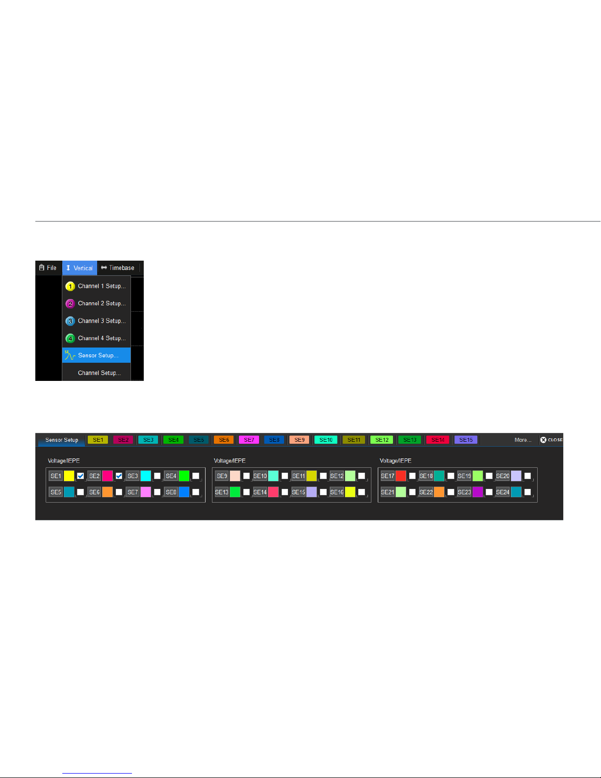
When the oscilloscope is started with a SAM40
Sensor Acquisition Module connected, the
oscilloscope Vertical menu will offer an option for
Sensor Setup. Choose this to open the Sensor
Setup dialog.
Conguring Sensor Input Channels
Similar to the Channel Setup dialog, Sensor Setup is a collection of all the available sensor input channels, allowing you to quickly enable/disable a
channel. Behind it are the individual Sensor (SEn) conguration dialogs. Select "More..." near the closebox to display additional tabs.
Page 7

SAM40 Operator’s Manual
5
BASICS
The Sensor dialogs contain many of the same settings as the Channel (Cn) conguration dialogs.
4 mA Bias
When the 4 mA Bias checkbox is selected, the SAM40 applies an excitation
current to IEPE/ICP sensor inputs. It is disabled when Coupling is set to
something other than IEPE.
Note: It is recommended to leave the 4 mA Bias checkbox deselected (the
default state) until sensors are connected, then select it prior to taking
measurements.
Bandwidth
The selectable bandwidth settings are Full (40 kHz), 2 kHz, 500 Hz, and
100 Hz. SAM40 inputs utilize a digital IIR lter to limit bandwidth.
Vertical Scale
As with channel traces, the Vertical Scale sets the amount of voltage (or
different vertical unit) represented by one Vertical division of the grid.
Coupling
When the input is an IEPE/ICP-compatible sensor, check <24 Vpk Input
(max. input for IEPE sensors) and select IEPE from the Coupling eld.
Otherwise, for a voltage input, you may leave <24 Vpk Input unchecked
and select DC1MΩ, AC1MΩ, or Ground coupling.
Note: Maximum input voltage is 50 Vpk for DC1MΩ, AC1MΩ and Ground
coupling, but only 24 Vpk for IEPE coupling.
Page 8

928571-00 Rev A
6
To rescale a sensor trace to a unit other than Volts or Amperes, on the
SEn dialog choose Vertical Unit Others, then select the Sensor Setup
button to display the rescale settings:
Unit Category is the unit type, for example, Length or Velocity.
Units reflect the category selection, for example, a Length unit of meters
(m) versus a Velocity unit of meters per second (m/s).
Units/V (slope) is the multiplication factor (a) used to scale the acquired
sensor Voltage. Enter the number of the new unit that will equal 1 Volt.
Add is the amount of additive constant (b) to add to the rescaled value.
This value is always given in the new unit.
Rescaling
Most sensors output voltage values. The SAM40 rescale settings allow
you to change the units in which sensor output values are displayed to
a much wider selection than Volts or Amperes. They can also be used
for intelligent rescaling of output values, equivalent to using the Rescale
math function (y=ax+b), where:
• a is the multiplication factor (Units/V)
• b is the additive constant (Add)
Tip: Analog channels, parameters, and math functions can be rescaled
to many of the same units as sensors by using the Units subdialog next
to the main setup dialogs For instructions, see your oscilloscope online
Support or Operator's Manual.
As with channel rescaling, measurements performed on this sensor are
converted and displayed in the selected unit. However, math functions
are displayed in the unit that is logically appropriate for the result,
including complex results that must be derived from a table of core
SI units.
Units are automatically rescaled up or down within the list of SI unit
prefixes based on the relative size of the input signal.
BASICS
Example: Multiplying one sensor trace in Volts per meter by another
sensor trace in meters yields a result in Volts.
Example: 1000 V is displayed as 1 kV, while .1 V is displayed
as 100 mV. When the rescale value is 1 V = 1 Pascal (Pa), a 1
milliVolt (mV) reading is displayed as 1 mPa rather than .001 Pa
or 100e-3 Pa.
Page 9

SAM40 Operator’s Manual
7
Sensor signals with unit conversion. The math function applied to these signals (F7) is automatically shown in the
logically appropriate unit for the product of Amperes and Volts—Watts.
The Units subdialog offers a selection
of alternative units in the equivalent
dimension to Watts for the F7 trace.
BASICS
For math functions and measurements parameters, a further unit override is possible on the Units subdialog, which shows a selection of units in the
equivalent dimension to the unit of the Fn or Pn source trace. For example, while the default unit for the product of Volts and Amperes would be Watts, a
user could choose to instead display this function as Volt-Amperes Reactive (VAR) or horsepower (hp).
Page 10

928571-00 Rev A
8
BASICS
Further rescaling and changing units of one of the sensor traces
to Coulombs produces another automatic rescaling and unit
conversion for the math trace F7—this time to Joules.
Another math function (F12) applied to math trace F7 once again
yields the appropriate unit for the derivative of Joules, Watts.
Page 11

SAM40 Operator’s Manual
9
BASICS
Units of Measure
Channel and sensor traces may be displayed in the following units. Use the notation in the Code column when specifying these units in remote control
programs and customization scripts.
Note: Use only the base unit in code. The system automatically calculates prefixes based on the operation, timebase, and relative size of the input
signals. Some additional units are available for math functions and measurement parameters; these are shown on the respective Units subdialog.
Other Code
% percent PCT
Mass Code
g grams G
slug slugs SLUG
Length Code
m meters M
in inches IN
ft feet FT
yd yards YARD
mi miles MILE
Volume Code
L liters L
m
3
cubic meters M3
in
3
cubic inches IN3
ft
3
cubic feet FT3
yd
3
cubic yards YARD3
Angle Code
rad radians RAD
° arcdegrees DEG
arcmin arcminutes MNT
arcsec arcseconds SEC
cyc cycles CYCLE
rev revolutions REV
turn turns TURN
Force/Weight Code
N Newtons N
gr grains GR
oz ounces OZ
lb pounds LB
Velocity Code
m/s meters/second M/S
in/s inches/second IN/S
ft/s feet/second FT/S
yd/s yards/second YARD/S
mi/s miles/second MILE/S
Acceleration Code
m/s
2
meters/s
2
M/S2
in/s
2
inches/s
2
IN/S2
ft/s
2
feet/s
2
FT/S2
g
0
standard gravity GN
More on next page...
Page 12

928571-00 Rev A
10
Units of Measure
BASICS
Rotating Machine Code
rad/s radians/second RADPS
Hz frequency (Hertz) HZ
rps revolutions/second RPS
rpm revolutions/minute RPM
in•oz torque INOZ
in•lb torque INLB
ft•lb torque FTLB
N•m torque NM
W power, mechanical (Watts) W
hp horsepower HP
Electrical Code
A Amperes A
V Volts V
W power, real (Watts) W
VA power, apparent VA
VAR power, reactive VAR
PF power factor PF
F capacitance (Farads) F
C Coulombs C
Ω Ohms OHM
Sie Siemens SIE
V/m electric eld strength V/M
C/m
2
electric displacement eld CPM2
F/m permittivity FARADPM
Sie/m conductivity SIEPM
Magnetic Code
Wb Webers WB
T Teslas T
H inductance (Henrys) H
A/m magnetic eld strength A/M
H/m permeability HENRYPM
Pressure Code
Pa Pascals PAL
bar bars BAR
at atmosphere, technical AT
atm atmosphere, standard ATM
Torr Torr TORR
psi pounds/square inch PSI
Energy Code
J Joules J
BTU British Thermal Units BTU
cal calories CAL
Temperature Code
K degrees Kelvin K
°C degrees Celsius CEL
°F degrees Fahrenheit FAR
Page 13

SAM40 Operator’s Manual
11
MAINTENANCE
Sample Rate
The far right of the Timebase dialog shows the rate at which the SAM40
is sampling.
When the oscilloscope is sampling at a fixed rate, the SAM40 will sample
at a maximum rate of 100 kS/s so long as the oscilloscope Sample Rate
and Time/div settings allow it.
When the oscilloscope is set to Max Memory mode, increasing the
Time/div will decrease the SAM40 sample rate below 100 kS/s once the
Time/div requires it.
Regardless of the SAM40 sample rate, the timebase is locked to the
oscilloscope, and sensor traces will always be time synchronous with
channel traces.
Maintenance
Cleaning
Clean the outside of the SAM40 using a soft cloth moistened with water
or isopropyl alcohol solution. Do not use harsh or abrasive cleansers. Dry
thoroughly before using. Do not submerge the instrument or allow moisture to penetrate it.
Calibration
Schedule factory calibration once per year. Contact your local Teledyne
LeCroy office for service.
Firmware Updates
The SAM40 requires the matched version of MAUI firmware (XStreamDSO).
You will not be able to install the SAM40 firmware unless the correct
version of MAUI is present on the oscilloscope; likewise, if you update
MAUI, you must also update the SAM40. Firmware can be found at
teledynelecroy.com/support/softwaredownload under Oscilloscope
Downloads > Firmware Updates. Register on our website for notices of
periodic firmware updates.
1. Download SAM_Installer.exe onto a portable USB drive or directly to the
oscilloscope desktop if it has an internet connection.
2. Select File > Exit to close the oscilloscope application.
3. With the SAM40 connected to the oscilloscope and powered on, use
Windows Explorer to navigate to and launch SAM_Installer.exe. Connect
portable drives to any oscilloscope host USB port.
4. Follow the installer prompts, accepting all installed software and
license agreements.
5. When finished, power cycle the SAM40 and the oscilloscope.
Page 14

928571-00 Rev A
12
Precautions
Use proper power cord. Use only the power cord shipped with this
instrument and certified for the country of use.
Maintain ground. This product is grounded through the power cord
grounding conductor. To avoid electric shock, connect only to a grounded
mating outlet.
Observe all terminal ratings. Do not apply a voltage to any input that
exceeds the maximum rating of that input. Refer to the markings next to
the BNC terminals for maximum allowed values.
Use only within operational environment listed. Do not use in wet or
explosive environment. Use indoors only.
Keep product surfaces clean and dry.
Do not block the cooling vents. Leave a minimum six-inch (15 cm) gap
between the instrument and the nearest object.
Do not remove the covers or inside parts. Refer all maintenance to
qualified service personnel.
Do not operate with suspected failures. Check body and cables regularly.
If any part is damaged, cease operation immediately and sequester the
instrument from inadvertent use.
Safety
Observe generally accepted safety procedures in addition to the
precautions listed here.
Operating Environment
Temperature: 0 °C to 50 °C
Humidity: Maximum RH 90% (non-condensing) up to 30 °C
decreasing linearly to RH 50% at 50 °C.
Altitude: Up to 10,000 ft (3,048 m) at or below 25 °C
Power
AC Power: 100 - 240 VAC (±10%) at 50/60 Hz (±10%), or
100 - 120 VAC (±10%) at 400 Hz (±5%)
Max.
Consumption: 50 W (50 VA)
Symbols
These symbols appear on the body of the instrument.
SAFETY
CAUTION of potential damage to equipment, or WARNING of
potential bodily injury. Do not proceed until the accompanying
information is fully understood and conditions are met.
Frame/chassis ground connection.
Power On.
Standby Power (Off).
Page 15

SAM40 Operator’s Manual
13
Service
If the SAM40 cannot be serviced on location, contact your service center
for a Return Material Authorization (RMA) code and instructions where to
ship the product. All products returned to the factory must have an RMA.
Return shipments must be prepaid. Teledyne LeCroy cannot accept COD
or Collect shipments. We recommend air freighting. Insure the item you’re
returning for at least the replacement cost.
Follow these steps for a smooth product return.
1. Remove all accessories from the device. Do not include the manual.
2. Pack the product in its case, surrounded by the original packing
material (or equivalent).
3. Label the case with a tag containing:
• The RMA
• Name and address of the owner
• Product model and serial number
• Description of failure or requisite service.
4. Pack the product case in a cardboard shipping box with adequate
padding to avoid damage in transit.
5. Mark the outside of the box with the shipping address. Add:
• ATTN: <RMA code assigned by Teledyne LeCroy>
• FRAGILE
6. If returning a product to a different country:
• Mark the shipment “Return of US manufactured goods for warranty
repair/recalibration.“
• List any cost of service in the Value column and the original purchase
price “For insurance purposes” only.
• Be very specific about the reason for shipment. Duties may have to be
paid on the value of the service.
SERVICE
Service Plans
Extended warranty, calibration, and upgrade plans are available for
purchase. Contact your Teledyne LeCroy sales representative or
customersupport@teledynelecroy.com to purchase a service plan.
Service Centers
For a complete list of Teledyne LeCroy offices by country, including our
sales and distribution partners, visit: teledynelecroy.com/support/contact
Teledyne LeCroy
700 Chestnut Ridge Road
Chestnut Ridge, NY, 10977, USA
teledynelecroy.com
Sales and Service:
Ph: 800-553-2769 / 845-425-2000
FAX: 845-578-5985
contact.corp@teledynelecroy.com
Support:
Ph: 800-553-2769
customersupport@teledynelecroy.com
Page 16

928571-00 Rev A
14
CERTIFICATIONS
Certications
Teledyne LeCroy certifies compliance to the following standards as of
the time of publication. Please see the EC Declaration of Conformity
document shipped with your product for current certifications.
EMC Compliance
EC DECLARATION OF CONFORMITY - EMC
The instrument meets intent of EC Directive 2014/30/EU for Electromagnetic
Compatibility. Compliance was demonstrated to the following specifications
listed in the Official Journal of the European Communities:
EN 61326-1:2013, EN 61326-2-1:2013 EMC requirements for electrical
equipment for measurement, control, and laboratory use.
1
Electromagnetic Emissions:
EN 55011:2010, Radiated and Conducted Emissions Group 1, Class A
2 3
EN 61000-3-2/A2:2009 Harmonic Current Emissions, Class A
EN 61000-3-3:2008 Voltage Fluctuations and Flickers, Pst = 1
Electromagnetic Immunity:
EN 61000-4-2:2009 Electrostatic Discharge, 4 kV contact, 8 kV air, 4 kV
vertical/horizontal coupling planes
4
EN 61000-4-3/A2:2010 RF Radiated Electromagnetic Field, 3 V/m,
80-1000 MHz; 3 V/m, 1400 MHz - 2 GHz; 1 V/m, 2 GHz - 2.7 GHz
EN 61000-4-4/A1:2010 Electrical Fast Transient/Burst, 1 kV on power
supply lines, 0.5 kV on I/O signal data and control lines
4
EN 61000-4-5:2006 Power Line Surge, 1 kV AC Mains, L-N, L-PE, N-PE
4
EN 61000-4-6:2009 RF Conducted Electromagnetic Field, 3 Vrms,
0.15 MHz - 80 MHz
EN 61000-4-11:2004 Mains Dips and Interruptions, 0%/1 cycle,
70%/25 cycles, 0%/250 cycles
4 5
1
To ensure compliance with all applicable EMC standards, use high-quality shielded interface cables.
2
Emissions which exceed the levels required by this standard may occur when the instrument is
connected to a test object.
3
This product is intended for use in nonresidential areas only. Use in residential areas may cause
electromagnetic interference.
4
Meets Performance Criteria “B” limits of the respective standard: during the disturbance, product
undergoes a temporary degradation or loss of function or performance which is
self-recoverable.
5
Performance Criteria “C” applied for 70%/25 cycle voltage dips and for 0%/250 cycle voltage
interruption test levels per EN61000-4-11.
European Contact:*
Teledyne LeCroy Europe GmbH
Im Breitspiel 11c
D-69126 Heidelberg
Germany
Tel: + 49 6221 82700
AUSTRALIA & NEW ZEALAND DECLARATION OF CONFORMITY – EMC
The instrument complies with the EMC provision of the Radio Communications
Act per the following standards, in accordance with requirements imposed by
Australian Communication and Media Authority (ACMA):
AS/NZS CISPR 11:2011 Radiated and Conducted Emissions, Group 1, Class A.
Australia / New Zealand Contacts:*
RS Components Pty Ltd. RS Components Ltd.
Suite 326 The Parade West Units 30 & 31 Warehouse World
Kent Town, South Australia 5067 761 Great South Road
Penrose, Auckland, New Zealand
* Visit teledynelecroy.com/support/contact for the latest contact information.
Page 17

SAM40 Operator’s Manual
15
Environmental Compliance
END-OF-LIFE HANDLING
The instrument is marked with this symbol to indicate that it
complies with the applicable European Union requirements to
Directives 2012/19/EU and 2013/56/EU on Waste Electrical and
Electronic Equipment (WEEE) and Batteries.
The instrument is subject to disposal and recycling regulations that vary
by country and region. Many countries prohibit the disposal of waste
electronic equipment in standard waste receptacles.
For more information about proper disposal and recycling of your
Teledyne LeCroy product, please visit teledynelecroy.com/recycle.
RESTRICTION OF HAZARDOUS SUBSTANCES (RoHS)
This instrument and its accessories conform to the 2011/65/EU RoHS2
Directive.
ISO Certification
Manufactured under an ISO 9000 Registered Quality Management System.
Safety Compliance
EC DECLARATION OF CONFORMITY – LOW VOLTAGE
The oscilloscope meets intent of EC Directive 2014/35/EU for Product
Safety. Compliance was demonstrated to the following specifications as
listed in the Official Journal of the European Communities:
EN 61010-1:2010 Safety requirements for electrical equipment for
measurement, control, and laboratory use – Part 1: General requirements
EN 61010-2:030:2010 Safety requirements for electrical equipment
for measurement, control, and laboratory use – Part 2-030: Particular
requirements for testing and measuring circuits
The design of the instrument has been verified to conform to the
following limits put forth by these standards:
•
Mains Supply Connector: Overvoltage Category II, instrument intended
to be supplied from the building wiring at utilization points (socket
outlets and similar).
•
Measuring Circuit Terminals: No rated measurement category.
Terminals not intended to be connected directly to the mains supply.
•
Unit: Pollution Degree 2, operating environment where normally only
dry, non-conductive pollution occurs. Temporary conductivity caused
by condensation should be expected.
CERTIFICATIONS
Page 18

928571-00 Rev A
16
WARRANTY
Warranty
NOTE: THE WARRANTY BELOW REPLACES ALL OTHER WARRANTIES, EXPRESSED
OR IMPLIED, INCLUDING BUT NOT LIMITED TO ANY IMPLIED WARRANTY OF
MERCHANTABILITY, FITNESS, OR ADEQUACY FOR ANY PARTICULAR PURPOSE OR
USE. TELEDYNE LECROY SHALL NOT BE LIABLE FOR ANY SPECIAL, INCIDENTAL,
OR CONSEQUENTIAL DAMAGES, WHETHER IN CONTRACT OR OTHERWISE. THE
CUSTOMER IS RESPONSIBLE FOR THE TRANSPORTATION AND INSURANCE
CHARGES FOR THE RETURN OF PRODUCTS TO THE SERVICE FACILITY.
TELEDYNE LECROY WILL RETURN ALL PRODUCTS UNDER WARRANTY WITH
TRANSPORT PREPAID.
The product is warranted for normal use and operation, within specifications, for
a period of three years from shipment. Teledyne LeCroy will either repair or, at our
option, replace any product returned to one of our authorized service centers within
this period. However, in order to do this we must first examine the product and find
that it is defective due to workmanship or materials and not due to misuse, neglect,
accident, or abnormal conditions or operation.
Teledyne LeCroy shall not be responsible for any defect, damage, or failure caused
by any of the following: a) attempted repairs or installations by personnel other than
Teledyne LeCroy representatives; b) improper connection to incompatible equipment;
or c) for any damage or malfunction caused by the use of non-Teledyne LeCroy
supplies. Furthermore, Teledyne LeCroy shall not be obligated to service a product
that has been modified or integrated where the modification or integration increases
the task duration or difficulty of servicing the instrument. Spare and replacement
parts, and repairs, all have a 90-day warranty.
The instrument's firmware has been thoroughly tested and is presumed to be
functional. Nevertheless, it is supplied without warranty of any kind covering
detailed performance. Products not made by Teledyne LeCroy are covered solely by
the original manufacturer's warranty.
Page 19

SAM40 Operator’s Manual
17
Page 20

© 2017 Teledyne LeCroy, Inc. All rights reserved.
928571-00 Rev A,
October, 2017
 Loading...