

Page 1
Operator’s
Manual
MS-500 Mixed Signal
Oscilloscope Option
Page 2

Page 3

MS-500
Mixed-Signal Oscilloscope Option
Operator’s Manual
January 2013
Page 4

© 2013 Teledyne LeCroy, Inc. All rights reserved.
Unauthorized duplication of Teledyne LeCroy documentation materials other than for
internal sales and distribution purposes is strictly prohibited. However, clients are
encouraged to distribute and duplicate Teledyne LeCroy documentation for their own
internal educational purposes.
Teledyne LeCroy is a registered trademark of Teledyne LeCroy, Inc. Windows is a registered
trademark of Microsoft Corporation. Other product or brand names are trademarks or
requested trademarks of their respective holders. Information in this publication supersedes
all earlier versions. Specifications are subject to change without notice.
Warranty
NOTE: THE WARRANTY BELOW REPLACES ALL OTHER WARRANTIES, EXPRESSED OR IMPLIED,
INCLUDING BUT NOT LIMITED TO ANY IMPLIED WARRANTY OF MERCHANTABILITY, FITNESS,
OR ADEQUACY FOR ANY PARTICULAR PURPOSE OR USE. TELEDYNE LECROY SHALL NOT BE
LIABLE FOR ANY SPECIAL, INCIDENTAL, OR CONSEQUENTIAL DAMAGES, WHETHER IN
CONTRACT OR OTHERWISE. THE CUSTOMER IS RESPONSIBLE FOR THE TRANSPORTATION
AND INSURANCE CHARGES FOR THE RETURN OF PRODUCTS TO THE SERVICE FACILITY.
TELEDYNE LECROY WILL RETURN ALL PRODUCTS UNDER WARRANTY WITH TRANSPORT
PREPAID.
The MS 500 is warranted for normal use and operation, within specifications, for a period of
three years from shipment. Teledyne LeCroy will either repair or, at our option, replace any
product returned to one of our authorized service centers within this period. However, in
order to do this we must first examine the product and find that it is defective due to
workmanship or materials and not due to misuse, neglect, accident, or abnormal conditions
or operation.
Teledyne LeCroy shall not be responsible for any defect, damage, or failure caused by any of
the following: a) attempted repairs or installations by personnel other than Teledyne LeCroy
representatives or b) improper connection to incompatible equipment, or c) for any damage
or malfunction caused by the use of non-Teledyne LeCroy supplies. Furthermore, Teledyne
LeCroy shall not be obligated to service a product that has been modified or integrated
where the modification or integration increases the task duration or difficulty of servicing
the oscilloscope. Spare and replacement parts, and repairs, all have a 90-day warranty.
922245-00 Rev A
January 2013
Page 5

Operator’s Manual
922245-00 Rev A
i
B
TABLE OF CONTENTS
Welcome .................................................................................. 1
Safety Instructions .................................................................... 2
Symbols ..................................................................................... 2
Precautions ............................................................................... 2
Operating Environment ............................................................ 3
Cleaning..................................................................................... 3
Returning a Product for Service or Repair ................................ 3
Technical Support ..................................................................... 4
Staying Up-to-Date .................................................................... 4
Standard Equipment ................................................................. 5
MS-500 Standard Hardware ..................................................... 5
The MS-500 Software ............................................................... 7
Accessories ................................................................................ 7
Description of Operation ......................................................... 10
Getting Started with the MS-500 ............................................. 11
Overview ................................................................................. 11
Connecting MS-500 to the Oscilloscope ................................. 12
Verifying Proper Connection to Oscilloscope
and Device Under Test ............................................................ 14
Digital Connections ................................................................. 15
Threshold Levels ..................................................................... 16
Minimum Voltage Swing ......................................................... 16
Accessing the MS-500 Toolset ................................................ 17
Oscilloscope Analog Trigger and MS-500 Digital Trigger ........ 18
Digital Trace Groups ................................................................ 19
Digital Logic Threshold Setup .................................................. 22
Digital Trigger Setup ................................................................ 24
Logic Bus Trigger Setup ........................................................... 26
Digital Logic Threshold Setup .................................................. 27
Page 6

MS-500 Mixed Signal Oscilloscope Option
ii
922245-00 Rev A
Characterize Digital or Mixed Signal ........................................ 28
System Performance Overview .............................................. 28
Using Cursors.......................................................................... 28
Using Measurement Parameters ........................................... 29
Measurement Gating ............................................................. 30
Using Statistics and Graphing ................................................. 30
Isolate and Analyze Signal Activity .......................................... 31
Zooming Waveforms .............................................................. 31
Reference ............................................................................... 33
Certifications .......................................................................... 33
Specifications ......................................................................... 36
Contact Teledyne LeCroy ....................................................... 38
Page 7

Operator’s Manual
922245-00 Rev A 1
Welcome
Thank you for purchasing a Teledyne LeCroy MS-500.
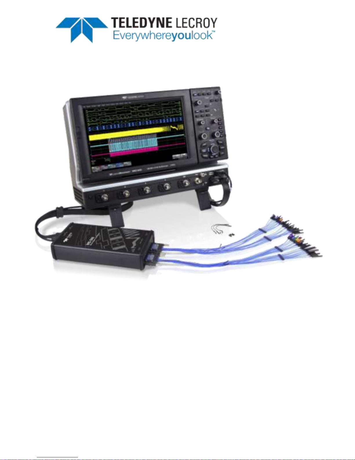
The MS-500 Mixed Signal Oscilloscope Option is a powerful solution for the
challenge of measuring multiple, mixed signals in a single oscilloscope. An
enhancement to the Teledyne LeCroy oscilloscopes, the MS-500 extends
their testing range by adding 18 or 36 digital channels for display or
triggering.
The MS-500 is ideally suited for embedded controller testing where there is
a proliferation of analog signals coincident with digital signals. Users can
easily debug signals using standard oscilloscope tools such as cursors,
measurement parameters, and zooming. Both oscilloscopes compatible
with the MS-500 feature large, bright color displays to facilitate signal
viewing, plus all the connectivity and documentation capabilities needed to
quickly record and distribute information.
The MS-500 and MS-500-36 are identical except the MS-500-36 standard
configuration is for 36 channels. The MS-500-36 can be operated in 36 or
18 channel mode for higher performance. The MS-500 is configured as an
18 channel instrument and can be upgraded with an additional lead set to
support 36 channels. Both are referred to as MS-500 in this manual.
This MS-500 manual assumes that you have a basic understanding of
discrete electronics, logic analyzers, and Teledyne LeCroy oscilloscopes,
specifically the model you will use with the MS-500. When necessary,
details on specific oscilloscope features are included in this manual.
Contact your nearest Teledyne LeCroy customer service center or national
distributor if anything is missing or damaged. We can only be responsible
for replacement if you contact us immediately.
Sincerely,
David C. Graef
Teledyne LeCroy Corporation
Vice President and Chief Technology Officer
Page 8
MS-500 Mixed Signal Oscilloscope Option
2
922245-00 Rev A
Safety Instructions
This section contains instructions that must be observed to keep the
instrument operating in a correct and safe condition. You are required to
follow generally accepted safety procedures in addition to the precautions
specified in this section. The overall safety of any system incorporating
this instrument is the responsibility of the assembler of the system.
Symbols
These symbols appear on the instrument's front or rear panels and in its
documentation to alert you to important safety considerations.
CAUTION of damage to instrument, or WARNING of hazard to health.
Attend to the accompanying information to protect against personal
injury or damage. Do not proceed until conditions are fully
understood and met.
ELECTROSTATIC DISCHARGE (ESD) HAZARD. Susceptible to damage if
anti-static measures are not taken.
DOUBLE INSULATION
Precautions
Connect and disconnect properly.
Do not overload. To avoid electric shock or fire, do not apply any potential
to the signal leads that exceeds the maximum rating of the instrument.
Refer to Specifications section of the manual for details.
Comply with voltage derating curve. When measuring higher frequency
signals, comply with the Voltage vs. Frequency Derating Curve, contained in
the Specifications section of the manual.
Use only within operational environment listed. Do not use in wet or
explosive atmospheres.
Use indoors only.
Keep product surfaces clean and dry.
Do not operate with suspected failures. Do not use the product if any part
is damaged. Cease operation immediately and sequester the instrument
from inadvertent use.
Page 9

Operator’s Manual
922245-00 Rev A 3
Operating Environment
Temperature:
5 to 40 °C
Humidity:
Maximum relative humidity 80% (non-condensing)
for temperatures up to 31° C decreasing linearly to
50% relative humidity at 40° C
Altitude:
Up to 2,000 m
Cleaning
Clean only the exterior of the instrument using a damp, soft cloth. Do not
use harsh chemicals or abrasive elements. Under no circumstances
submerge the instrument or allow moisture to penetrate it.
CAUTION. Do not attempt to clean internal parts. Refer to qualified
service personnel.
Returning a Product for Service or Repair
If you suspect that you have a problem with the MS-500, you should first
contact your local Teledyne LeCroy service center so that they can
ascertain whether this component is defective.
If you need to return a Teledyne LeCroy product, provide model
identification by providing the model name and serial number, describe the
defect or failure, and give us your name and telephone number. For factory
returns, use a Return Authorization Number (RAN), which you can get from
customer service. Write the number clearly on the outside of the shipping
carton. Return products requiring only maintenance to your local customer
service center. Within the warranty period, transportation charges to the
service center are your responsibility.
Products under warranty are then returned to you with transport prepaid
by Teledyne LeCroy. Outside the warranty period, you provide us with a
purchase order number before the work can be done. You are also billed
for parts and labor related to the repair work and shipping.
It is highly recommended to prepay return shipments and use air freight.
Teledyne LeCroy cannot accept COD (Cash On Delivery) or Collect Return
shipments.
Page 10

MS-500 Mixed Signal Oscilloscope Option
4
922245-00 Rev A
Technical Support
You can get assistance with installation and operation from your customer
service center. Visit the Teledyne LeCroy Web site at teledynelecroy.com
for the center nearest you.
Staying Up-to-Date
Your MS-500 hardware does not need periodic calibration.
Teledyne LeCroy offers state-of-the-art performance by continually refining
and improving the instrument’s capabilities and operation. We frequently
update both firmware and software during service, free of charge during
warranty. Therefore, MS-500 specific software may be periodically
updated. You can download firmware and software updates from the
Teledyne LeCroy website.
Since software is continuously updated, the dialog boxes and menus you
see in your program may be slightly different than what is shown in this
manual. These differences should not affect your understanding of
correctly operating the MS-500.
Page 11
Operator’s Manual
922245-00 Rev A 5
Standard Equipment
MS-500 Standard Hardware
The Standard Hardware consists of the following items:
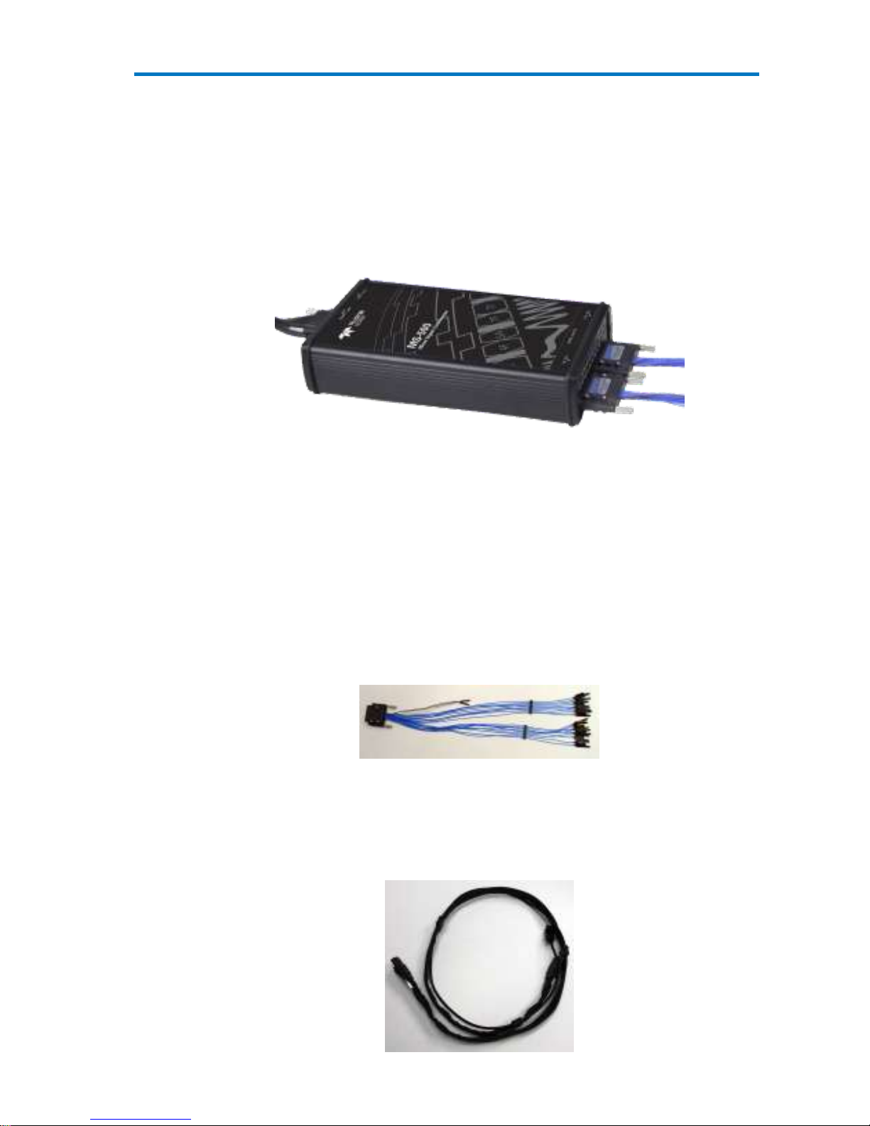
Qty. 1 Mixed Signal Oscilloscope Option – Provides 18 or 36
channel digital acquisition and triggering.
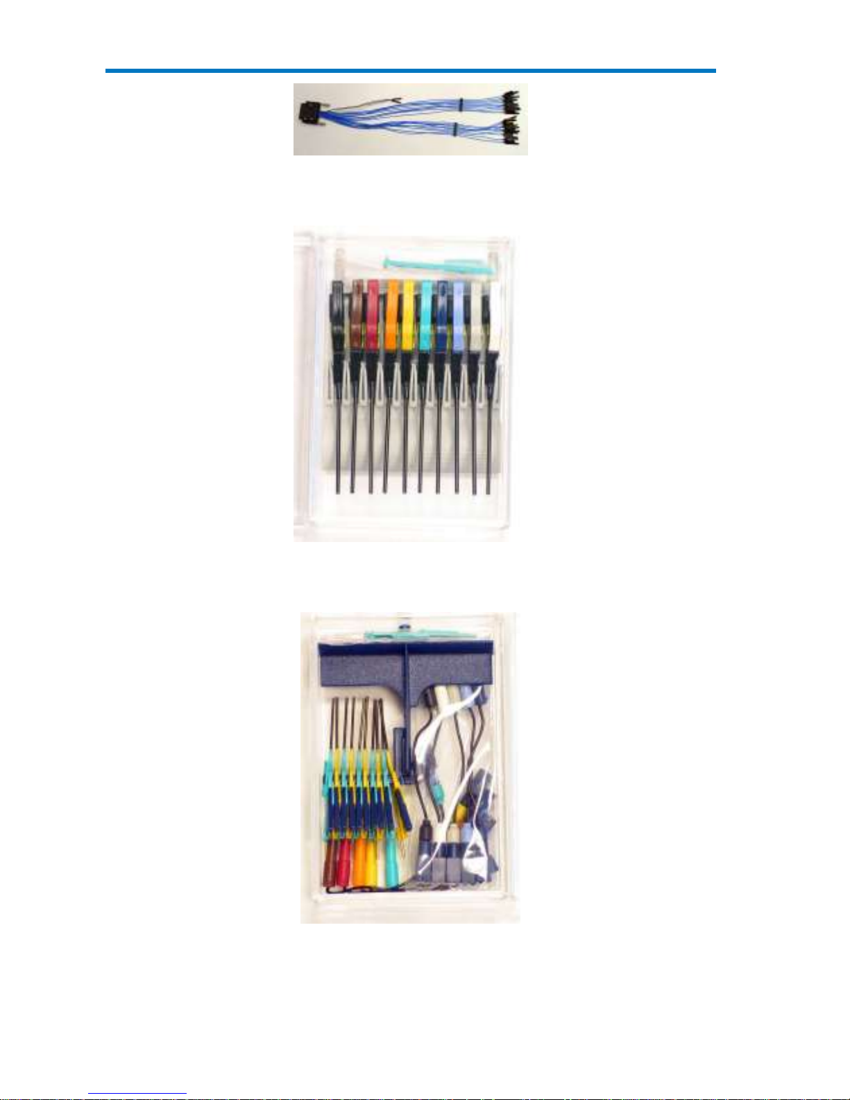
Qty. 1 16” (40.64 cm) Digital Lead Set – Interfaces the MS-500 to
the device under test. The lead set terminates in a 25 mil pin
socket. Micro-gripper probes of various sizes are available as
accessories from Teledyne LeCroy, and may be connected to the
lead set. (Qty.2 provided with MS-500-36)
The lead set is divided into two groups. Each lead within the group
is color-coded (to resistor color-coding standard) and has an
individual ground connection. In addition, there are two common
ground leads available for use.
Qty. 1 Teledyne LeCroy Bus Cable – 1.3m cable to connect Mixed
Signal Hardware to main oscilloscope unit, includes USB2.0 cable.
This connection provides timebase synchronization, crosstriggering and power.
Page 12

MS-500 Mixed Signal Oscilloscope Option
6
922245-00 Rev A
Qty. 5 3” Flexible Ground Lead – Lead for grounding individual
digital inputs (Qty. 10 for MS-500-36)
Qty. 20 Ground Extender – Connect to ground port of any digital
input and make a simple signal and ground connection to a 0.1”
square pin header. (Qty. 40 with MS-500-36
Qty. 1 Carrying Case
Page 13
Operator’s Manual
922245-00 Rev A 7
Qty. 1 Quick Reference Guide
Qty. 1 Operator’s Manual
The MS-500 Software
The standard MS-500 software adds the following capability to the
Teledyne LeCroy oscilloscope software dialogs:
Analog, Digital and Combination Trigger Modes – Allows you to
choose whether to set an analog trigger condition, a digital trigger
condition or a pattern consisting of analog and digital signals.
Digital Trigger – Allows a digital trigger condition to be set from
within the oscilloscope using an easy-to-understand interface.
Digital Channels – Provides a standard, general purpose setup for
defining the digital channels and displaying digital lines.
Digital Threshold Setup – Provides the means to define a logic
threshold for digital trace calculation.
The MS-500 Hardware and Software requires no traceable calibration or
adjustment. However, the oscilloscope used with the MS-500 does require
periodic calibration and adjustment.
Accessories
The following accessories are also available for use with the MS-500.
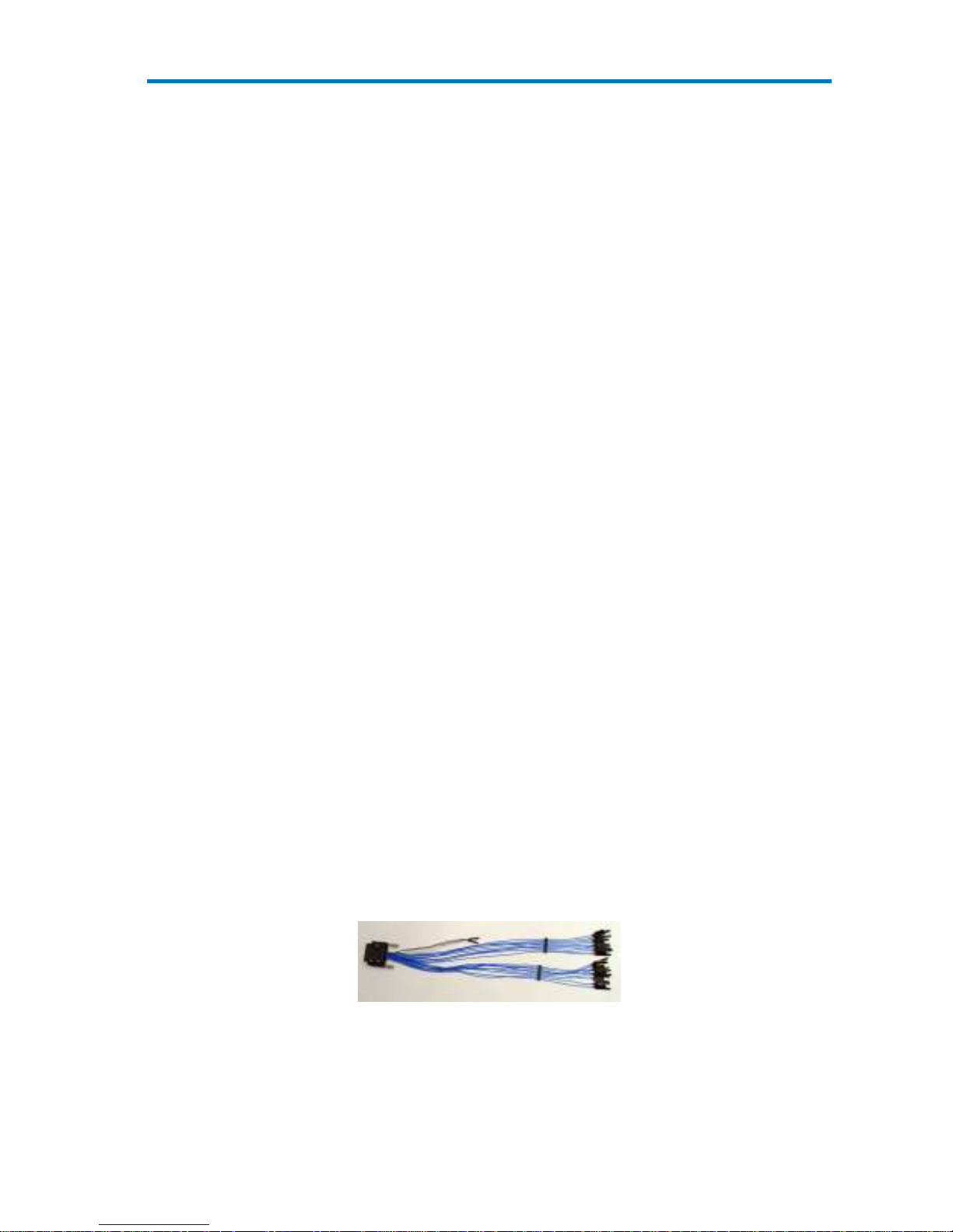
MSO-DLS-18 16” (40.64 cm) Digital Lead Set – You may find an
additional standard digital lead set convenient if you have more
than one device under test and do not wish to
disconnect/reconnect your cables (when using the MS-500 on
different DUTs). Inputs are labeled D0 – D17.
MSO-DLS-36 16” (40.64 cm) Digital Lead Set – An additional digital
lead set. This might be convenient to have if you have more than
one device under test and do not wish to disconnect/reconnect
your cables to use the MS-500 on different DUTs. Adding this to the
MS-500 enables 36 channels. Inputs are labeled D18 – D35
Page 14
MS-500 Mixed Signal Oscilloscope Option
8
922245-00 Rev A
PK400-1 – Large gripper probe set for 0.10 inch (2.54 mm) pin
pitch. Includes 10 probes with color-coded leads.
PK400-2 – Medium gripper probe set for 0.04 inch (1.0 mm) pin
pitch. Includes 10 probes with color-coded leads.
Page 15

Operator’s Manual
922245-00 Rev A 9
PK400-3 – Small gripper probe set for 0.008 inch (0.2 mm) pin
pitch. Includes 10 probes with color-coded leads.
MSO-MICTOR – Mictor Connection cable, 16” (40.64 cm), 36
channel connector.
MSO-3M - Interconnect cable, 16” (40.64 cm) mates with 3M
connectors, 2520-6002 and 25205002..
Page 16

MS-500 Mixed Signal Oscilloscope Option
10
922245-00 Rev A
Description of Operation
The various components of the MS-500 Mixed Signal Oscilloscope Option
acquire and store digital data, trigger on digital patterns, interface the
external module to the oscilloscope, and provide a user-friendly interface
for control and interpretation of data.
The MS-500 is an external device that digitally samples waveform data at
up to 2 GS/s (for 500 MHz digital signals). Unlike a logic analyzer, it
operates only in a Timing Analysis mode, so it requires 4x oversampling to
determine the correct digital edge position, and does not require the user
to input a clock.
While in SINGLE, NORMAL, or AUTO trigger mode, the MS-500 repeatedly
samples each digital channel’s voltage level. If the voltage is greater than
the threshold voltage, the MS-500 stores a 1 in internal memory.
Otherwise, a 0 is stored.
1
Threshold level
1 1 1 1 1 0 0 0 0 1 1 1 1 1 0 0 0 0 0
The minimum high voltage level is user definable by the hysteresis control
up to 1.4 V above the threshold. The maximum low voltage level is user
definable by the hysteresis control up to 1.4 V below the threshold. The
minimum signal swing is 100 mV. The indeterminate range of 50 mV
around the threshold voltage level is the level below which the MS-500 will
not operate. However, the MS-500 can support a signal as low as 100 mV
only if the input signal’s quality is adequate.
The MS-500 keeps sampling its inputs until the oscilloscope is put into STOP
trigger mode. Data is stored in a 50 Mpt internal memory that is
periodically transferred to the oscilloscope via the USB2.0 cable. If the
oscilloscope is triggering in SINGLE or NORMAL trigger mode, data is
Page 17

Operator’s Manual
922245-00 Rev A 11
acquired and transferred only when the trigger condition is satisfied. The
captured data is then displayed on the oscilloscope grid in a time-aligned
fashion.
In any trigger mode (AUTO, NORMAL, SINGLE), pressing STOP trigger
cancels the acquisition, which leaves the previously acquired data
unchanged.
The MS-500 both samples incoming data and searches for trigger
conditions.
The USB2.0 cable provides downloading of trigger conditions from the
oscilloscope to the MS-500 and uploading of digital data from the MS-500
to the oscilloscope.
Getting Started with the MS-500
Overview
The MS-500 is a complete system that interfaces with the oscilloscope in a
number of ways that make it easier to do the following:
Set analog, digital and combination triggers.
View all analog and digital signal information on the oscilloscope
grid, with all signals time-correlated
All setup is done in the user-friendly oscilloscope dialogs – it is not required
to leave the oscilloscope software to run the MS-500. All normal
oscilloscope tools (cursors, measurement parameters, etc.) are available
for use with the digital signals.
There are physical connections that must be made to ensure proper
operation, but the intuitive connection steps are documented here.
Operation of the specific Teledyne LeCroy oscilloscope is not covered in
this manual. Reference the On-Line Help or Getting Started Manual for
each oscilloscope for complete information on analog triggering, display of
analog signals, front panel operation, etc.
Page 18

MS-500 Mixed Signal Oscilloscope Option
12
922245-00 Rev A
Connecting MS-500 to the Oscilloscope
1. Connect the Teledyne LeCroy Bus Cable to the Teledyne LeCroy Bus
connector on the side of the oscilloscope and fasten the thumb
screws.
2. Connect the USB 2.0 cable (attached to the Teledyne LeCroy Bus
cable) to any of the side mounted USB ports on the oscilloscope.
3. Connect the other end of the Teledyne LeCroy Bus cable to the MS-
500 and fasten the thumb screws.
Page 19

Operator’s Manual
922245-00 Rev A 13
4. Connect the other end of the USB2.0 Cable to the MS-500.
5. Connect the Digital Lead Set to the other end of the MS-500
(labeled Digital Inputs, D0 – D17) and fasten the thumb screws. For
MS-500-36 repeat this process with the lead set labeled D18 – D35.
NOTE: Each digital line has a ground connection for optimal
performance. Two additional ground leads common to the whole
lead set are also available.
6. Connect the Digital Leads to the digital lines you wish to observe
(using accessory micro-grippers, as necessary or desired).
7. Turn on power to the oscilloscope and wait for the oscilloscope
application to begin.
Page 20

MS-500 Mixed Signal Oscilloscope Option
14
922245-00 Rev A
Verifying Proper Connection to Oscilloscope
and Device Under Test
If you are concerned that your digital signals aren’t being displayed
correctly, it is a good idea to check by viewing the digital signals one at a
time with an analog channel. This can point out errors in your connection
or in your logic threshold setup.
When your system is connected properly it looks like the following photo:
It is usually easiest to debug digital line connection or display problems by
viewing the digital information on an analog channel to confirm its
presence, then working back through the previous sequence to determine
where the connection or display error is.
CAUTION. Handle with care! The MS-500 Digital Lead Set connectors
are fragile. Pull the connector base, not the wire. Never bend the
connectors.
Page 21

Operator’s Manual
922245-00 Rev A 15
Digital Connections
Channel Groupings
Each 18 channel lead set is divided into two physical groups of 9 and each
group is bundled with a plastic separator. When using 36 channels there
are 4 groups of 9 leads.
NOTE: The grouping you assign to the digital lines in the software interface
can be different than the physical grouping of digital lines. The physical
grouping is intended for easy identification of all 18 digital lines.
Connector Colors
The wires in each color group use 9 repeating colors. The color sequence
corresponds to the resistor color code making it easier to know the digital
line number without having to look at the label.
Standard Output Connection
The standard terminations on the digital lead sets can be pushed directly
onto 25-mil pins. MicroGrippers or NanoGrippers may also be used to
probe the test circuit’s pins. Teledyne LeCroy provides a selection of small,
medium, and large grippers for various pitch sizes. A more complete
selection of adapter probes is available for most chips from Emulation
Technology Inc., Yamaichi Inc., and other manufacturers.
Page 22

MS-500 Mixed Signal Oscilloscope Option
16
922245-00 Rev A
Threshold Levels
The threshold level determines how the input signal is interpreted. The
threshold level can be set in either the Digital Grouping Setup or Pattern
Trigger Setup dialogs (it is the same setup, but is in two different places for
operator convenience). Input voltages less than the threshold are
converted to 0. Input voltages greater than the threshold are converted to
Digitized
waveform
Input
signal
Threshold level
Sample points
The threshold levels can be set between –10.0 V and +10.0 V. TTL circuits
use a threshold voltage level of 1.58 V. ECL circuits use a threshold voltage
level of -1.39 V. Other threshold settings are available in the setup dialog.
Minimum Voltage Swing
The minimum high voltage level is user definable by the hysteresis control
up to 1.4 V above the threshold. The maximum low voltage level is user
definable by the hysteresis control up to 1.4 V below the threshold. The
minimum signal swing is 100 mV. The indeterminate range of 50 mV
around the threshold voltage level is the level below which the MS-500 will
not operate. However, the MS-500 can support a signal as low as 100 mV
only if the input signal’s quality is adequate.
Page 23

Operator’s Manual
922245-00 Rev A 17
Accessing the MS-500 Toolset
MS-500 trigger and digital line display tools are easily accessible in a variety
of ways. The MS-500 option adds additional dialogs (menus) to the existing
oscilloscope. These dialogs are defined as:
Digital setup – allows set up of the Digital lines and
definition/display of parallel buses. These dialogs are roughly
analogous to the analog Channel setup dialogs in terms of how
they are accessed and how they operate in the software. However,
there are no dedicated front panel controls for digital channels as
there are with analog channels.
Logic Setup – allows setup of the logic threshold value that defines
the digital trace.
When the MS-500 is connected to the oscilloscope, these dialogs are
conveniently accessed with just one or two touches of the screen, making
adjustment fast and easy.
Page 24

MS-500 Mixed Signal Oscilloscope Option
18
922245-00 Rev A
Oscilloscope Analog Trigger and MS-500
Digital Trigger
The addition of the MS-500 option adds enhanced triggering; the digital
channels are now available in the oscilloscope trigger menu as trigger
sources.
To operate the oscilloscope with a normal analog trigger, simply open the
trigger dialog, and then select one of the oscilloscope channels as the
source. For more information on setting up an Analog trigger, consult your
oscilloscope On-Line Help or Getting Started Manual.
When the MS-500 is connected to the oscilloscope, the trigger type
defaults to Pattern Trigger, and the Pattern Trigger tab is automatically
displayed on the oscilloscope display dialog. If desired, touch the Close
button to not display the dialog.
For convenience, the Digital Logic Setup dialog is displayed in both the
Trigger dialogs and the Digital dialogs. Logic Setup is where you can set the
crossing threshold for determining whether the logic level is a 1 or a 0.
Other ways to access the MS-500 Trigger dialogs include:
Touching the Trigger trace descriptor label. If the MS-500 is
connected to the oscilloscope, the dialog defaults to the Digital
Trigger tab. Follow the previous instructions to select either an
Analog or Digital trigger.
Page 25

Operator’s Manual
922245-00 Rev A 19
Touching Trigger → Trigger Setup on the menu bar. Then select
either an Analog or Digital trigger (as required).
Digital Trace Groups
These dialogs provide the ability to define up to 4 different groups of digital
signals, and associate from 1-36 digital lines with each group. Digital lines
may be associated with more than one group. As a group, the signals can
be resized, repositioned, named, stored to memory, collapsed into a bus
trace/value, or moved to a different grid (WaveRunner Xi Series only).
You can access these dialogs by touching Vertical on the menu bar, and
select one of the four Digital traces.
This turns the Digital trace ON and opens the corresponding dialog box.
Page 26

MS-500 Mixed Signal Oscilloscope Option
20
922245-00 Rev A
If the Digital trace is already ON, the trace descriptor label is highlighted
and you can configure the setup dialog for that Digital trace.
The Digital trace descriptor labels contain information about the Digital
Sample Rate (top line), the maximum number of digital samples (bottom
line), and the number of channels in the grouping (top right)
Digital Trace Group Setup
Digital trace groups are very similar to analog channels – they can be
turned ON or OFF, they can be increased in size, and they can be positioned
on the grid. You can also store them as waveform files. In software, they
are accessed through the same Vertical dialog as analog channels. Cursors
and most timing measurements also work with Digital traces.
Notable differences include the lack of sampling information in the trace
data and the lack of dedicated front panel controls (though some front
panel controls double as position and size controls when the Digital trace
group is active).
However, Digital trace groups have capability far beyond that of an analog
channel. Each Digital trace group can consist of 1-36 digital lines. You can
create up to four Digital trace groups, and each digital line can be used in as
many or as few groups as desired. You can choose to display the group of
digital lines as individual digital traces (one per line), or as a “collapsed” bus
with bus data values calculated on screen within the bus trace. Since there
are so many digital lines, Digital lines or buses can be renamed so that it is
easier to keep track of the multitude of digital signals on the screen.
Page 27

Operator’s Manual
922245-00 Rev A 21
Digital Trace Group Dialog
The following image shows the Digital trace group dialog with an overview
of its operation:
Provides a method to quickly turn all digital lines in the Digital trace group
OFF or ON. The default is for all digital lines to be ON. As lines are turned
OFF, they automatically resize to take up more of the grid and be easier to
see.
There are no dedicated front panel controls for Digital line
position or size. However, you can touch these controls
twice and enter in a unit-less value for position and size
using the pop-up keypad. Or you can touch them once,
and use the front panel adjust knob to adjust the value.
Another way is to activate the Digital trace group by
touching the trace descriptor label once and then using
the front panel channel controls (V/div and Offset) to
adjust the position and size.
You can view a group of digital traces as individual lines (Expand mode),
like this:
Page 28

MS-500 Mixed Signal Oscilloscope Option
22
922245-00 Rev A
Or collapsed into a bus (Collapse mode), like this:
Just select the appropriate button to get the view that you want.
You can rename the collapsed bus for easier identification
from the oscilloscope grid. For instance, if we were to name
Digital1 as ADDR, it would appear as follows on the grid:
Where ADDR appeared on the far left side of the grid. Very long bus names
can be used, but the longer the name; the more bus data is obscured.
You can store a Digital trace group to memory, or move it to
another grid, just like you would a Channel. These controls
function identically for Channels and Digital trace groups.
Digital Logic Threshold Setup
The threshold level determines how the input signal is interpreted. The
threshold level can be set in either the Digital Setup or Digital Trigger Setup
menus (it is the same setup, but is in two different places for operator
convenience). Input voltages less than the threshold are converted to 0.
Input voltages greater than the threshold are converted to 1.
Digitized
waveform
Input
signal
Threshold level
Sample points
Page 29

Operator’s Manual
922245-00 Rev A 23
The threshold levels can be set between -10.0 V and +10.0 V. TTL circuits
use a threshold voltage level of 1.58 V. ECL circuits use a threshold voltage
level of -1.39 V. Other threshold settings are available in the setup dialog.
The minimum high voltage level is user definable by the hysteresis control
up to 1.4 V above the threshold. The maximum low voltage level is user
definable by the hysteresis control up to 1.4 V below the threshold. The
minimum signal swing is 100 mV. The indeterminate range of 50 mV
around the threshold voltage level is the level below which the MS-500 will
not operate. However, the MS-500 can support a signal as low as 100 mV
only if the input signal’s quality is adequate.
The Digital Logic Threshold Setup dialogs are contained in both the Trigger
dialogs and in the Digital Setup dialogs. It is important to note that a
selection made in one location does affect the value in the other. Up to
four different logic levels can be selected: levels can be set for lines D0 to
D8, D9 to D17, D18 to D26 and D27 to D35. When connecting your lines,
make sure that all lines with like levels are connected to the same set of 9
digital lines.
Touch the Logic Setup tab to view the following dialog:
You can select various Logic Families, or select User Defined and define a
custom threshold crossing. Touch inside the Logic Family selection to view
a selection list.
Page 30

MS-500 Mixed Signal Oscilloscope Option
24
922245-00 Rev A
If you select User Defined, then you are able to define the voltage level.
Otherwise, the Voltage Level selection is grayed out.
Digital Trigger Setup
When the MS-500 option is loaded onto the oscilloscope, additional trigger
capabilities are added to the normal oscilloscope trigger. These new trigger
capabilities permit you to select digital lines as the sources for your
oscilloscope triggers such as Edge, Width, Glitch, Interval and Dropout.
Other triggers can work as combination triggers incorporating analog and
digital triggering capabilities. These triggers are Qualified (A-B Event
Trigger) and Logic Pattern Trigger.
Page 31

Operator’s Manual
922245-00 Rev A 25
Creating a Pattern Trigger
There are two different ways to trigger digitally as follows:
Logic – permits creation of a simple or complex
analog/digital cross-pattern trigger condition with a mix of 0,
1, rising edge, falling edge, either edge, or don’t care
conditions on up to 4 analog channels and 18 digital lines.
Logic Bus – permits creation of a digital trigger that
corresponds to a hexadecimal bus value for up to 18 digital
bits.
Filter Out Unstable Conditions – Use this filter to ignore short glitches in
logic state triggers that last less than 3.5ns. If the box is unchecked all logic
states are shown. This filter is enabled by default
Logic Pattern Trigger Setup
The Logic Pattern Trigger dialog, with detail on some of the setup
conditions, is shown in the following images:
Select a value for any of the digital lines by touching the existing value
(using either your finger or a mouse), opening the pop-up menu with a list
of choices, and then selecting one of the choices. Alternatively, you can set
Page 32

MS-500 Mixed Signal Oscilloscope Option
26
922245-00 Rev A
a hex value by byte (or view what the resulting hex value conversion).
Touch the arrow buttons to scroll to the next group of eight digital lines.
Note that you may set a digital line to any value in the Logic trigger setup
even if it is not defined as part of a Digital group.
PLEASE NOTE THE FOLLOWING:
You may set a digital line to any value in the Logic trigger setup
even if it is not defined as part of a Digital group.
You can set multiple digital lines to different edge conditions.
However, the edge conditions are always grouped in an OR trigger
condition.
Logic Bus Trigger Setup
The Logic Bus Trigger setup dialog is shown as follows:
The Logic Bus trigger dialog is very similar to the Digital Logic trigger dialog.
The main difference is that you must select a Digital source (Digital1,
Digital2, Digital3, or Digital4). In addition, only those bits that are defined
as part of that Digital group can be defined in the Logic Bus setup dialog. A
hexadecimal data value can be entered directly, or read as a result of the
binary setup.
Page 33

Operator’s Manual
922245-00 Rev A 27
Digital Logic Threshold Setup
The Digital Logic Threshold Setup dialogs are located on both the Trigger
and Digital Setup dialogs. It is important to note that a selection made in
one location does affect the value in the other. Four different logic levels
can be selected. One level can be set for each of the four groups D0 to D8,
D9 to D17, D18 to D26, and D27 to D35. When connecting your lines, make
sure all lines with like levels are connected to the same set of 9 digital lines
Touch the Logic Setup tab to view the following dialog:
You can select various Logic Families, or select User Defined and define a
custom threshold crossing. Touch inside the Logic Family selection to view
a selection list.
If you select User Defined, voltage level can be defined. Otherwise, the
Voltage Level selection is grayed out.
Page 34

MS-500 Mixed Signal Oscilloscope Option
28
922245-00 Rev A
Characterize Digital or Mixed Signal
System Performance Overview
The oscilloscope contains a number of built-in tools, such as cursors,
measurement parameters, statistics, and optional graphical analysis tools
that allow you to characterize your DUT’s performance. The number and
type of these tools change depending on the Teledyne Leroy oscilloscope
you are using and what other software options are loaded on your
instrument. The tools can be used on the Digital traces and buses just like
they are used on any channel.
You may want to use cursors for making single-shot timing measurements,
and measurement parameters when you need to accumulate statistical
data over many different acquisitions.
Using Cursors
Use horizontal cursors to mark locations on the waveform where the time
measurement should be done, then read the cursor values to establish the
measurement. As necessary, adjust the timebase or create zooms of the
channel(s) and the Digital trace groups to view the signal with enough
detail. This is a good method for single-shot / single measurements.
Page 35

Operator’s Manual
922245-00 Rev A 29
NOTE : When Horizontal (Time) cursors are ON, the hexadecimal bus values
for each Digital trace group appear on the Digital trace descriptor label.
This can be useful when trying to measure to a specific bus value.
Using Measurement Parameters
Measurement parameters can be used to make basic timing and other
measurements of your digital or mixed-signal system. Basic parameters,
such as Delay, Delta Delay, Frequency, Period, Width, and Duty Cycle (not
all parameters are available in WaveSurfer) can be used with a digital line
as a source.
Delay – Time from the trigger to the first transition at
the 50% crossing
Delta Delay – Time between the 50% crossing of first
transition of two waveforms
Duty Cycle – Percent of time data is above 50%
Frequency – Frequency of every cycle in a waveform
at the 50% level and positive slope
Period – Period of every cycle in a waveform at the
50% level and positive slope
Width – Width measured at the 50% level (can be
positive or negative slope)
Page 36

MS-500 Mixed Signal Oscilloscope Option
30
922245-00 Rev A
Measurement Gating
Gating is available on each parameter so you can set a measurement
window in which the parameter should be activated. This allows you to
eliminate unwanted portions of the acquisition from your measurement.
Select gating from the Measure dialog by selecting the tab for the
appropriate measurement (P1, P2, etc.) and then setting the start and stop
for the gate. Reference the oscilloscope’s On-Line Help for more
information on how to set gating.
Using Statistics and Graphing
Statistics and Histicons allow you to gather numerical and
visual information on the distribution of your various
measurements.
You can turn on Statistics and Histicons separately in the
Measure dialog. Simply touch the appropriate box to
checkmark it and turn it ON; or touch it again to turn it OFF.
In addition, some optional Teledyne LeCroy
programs add capability to produce larger
histograms and trends of your measurement
parameters. If you have this capability, then you
can access it through the Measurement Parameter setup dialog (the Px
tab)
Page 37

Operator’s Manual
922245-00 Rev A 31
Isolate and Analyze Signal Activity
The combination of Analog Triggering, Digital Triggering, Analog Capture,
Digital Capture, and normal oscilloscope features is a powerful combination
of tools that can make it very easy to find latent HW or SW problems in
your circuit. The oscilloscope is no longer a tool only for hardware
engineers. Now software engineers can easily visualize the mix of analog
and digital signals and relate it to programming code and operation.
Following are some common mixed signal analysis needs and methods.
Zooming Waveforms
There are a number of ways to zoom a mix of analog and digital signals. The
easiest method is to STOP the acquisition and then simply adjust the
timebase Time/Div and Delay knobs on the front panel.
Use the Time/Div knob to change the zoom ratio, and the Delay knob to
change the position.
NOTE: When you adjust timebase to zoom, the position adjustment is
limited by the maximum pre-trigger and post-trigger delay adjustment
available in your oscilloscope. Reference your oscilloscope manual for
specifications of these delays.
You can also zoom by drawing a box with a mouse pointer around the area
that you wish to zoom. Follow these steps:
Page 38

MS-500 Mixed Signal Oscilloscope Option
32
922245-00 Rev A
1. Select the area you wish to zoom by drawing a box around it with a
mouse pointer.
2. A second grid is created of the zoomed traces. Use either the Zoom
control knobs or the Vertical/Horizontal control knobs to adjust
the vertical and horizontal scale and position. Reference your
oscilloscope operator’s manual for more information
Reference your oscilloscope’s On-Line Help or Getting Started Manual for
complete information on zooming.
Page 39

Operator’s Manual
922245-00 Rev A 33
Reference
Certifications
This section certifies the instrument’s Electromagnetic Compatibility (EMC),
Safety and Environmental compliances.
EMC Compliance
EC DECLARATION OF CONFORMITY - EMC
The instrument meets intent of EC Directive 2004/108/EC for
Electromagnetic Compatibility. Compliance was demonstrated to the
following specifications as listed in the Official Journal of the European
Communities:
EN 61326-1:2006, EN 61326-2-1:2006 EMC requirements for electrical
equipment for measurement, control, and laboratory use.
Electromagnetic Emissions:
CISPR 11:2003, Radiated and Conducted Emissions Group 1, Class A
1 2
Electromagnetic Immunity:
EN 61000-4-2:2001 Electrostatic Discharge, 4 kV contact, 8 kV air, 4 kV
vertical/horizontal coupling planes 3
EN 61000-4-3:2006 RF Radiated Electromagnetic Field, 3 V/m, 80-1000
MHz; 3 V/m, 1400 MHz - 2 GHz; 1 V/m, 2 GHz - 2.7 GHz 3
1 Emissions which exceed the levels required by this standard may occur when the
leads are connected to a test object.
2 This product is intended for use in nonresidential areas only. Use in residential
areas may cause electromagnetic interference.
3 Meets Performance Criteria “B” limits of the respective standard: during the
disturbance, product undergoes a temporary degradation or loss of function or
performance which is self-recoverable.
European Contact:
Teledyne LeCroy Europe GmbH
Waldhofer Str 104
D-69123 Heidelberg, Germany
Tel: (49) 6221 82700
Page 40

MS-500 Mixed Signal Oscilloscope Option
34
922245-00 Rev A
AUSTRALIA & NEW ZEALAND DECLARATION OF CONFORMITY—EMC
The instrument complies with the EMC provision of the Radio
Communications Act per the following standards, in accordance with
requirements imposed by Australian Communication and Media Authority
(ACMA):
CISPR 11:2003 Radiated and Conducted Emissions, Group 1, Class A, in
accordance with EN61326-1:2006 and EN61326-2-1:2006.
Australia / New Zealand Contacts:
Vicom Australia Ltd.
1064 Centre Road
Oakleigh, South Victoria 3167
Australia
Vicom New Zealand Ltd.
60 Grafton Road
Auckland
New Zealand
Safety Compliance
EC DECLARATION OF CONFORMITY – LOW VOLTAGE
The instrument meets intent of EC Directive 2006/95/EC for Product Safety.
Compliance was demonstrated to the following specifications as listed in
the Official Journal of the European Communities:
EN 61010-1:2010 Safety requirements for electrical equipment for
measurement, control, and laboratory use – Part 1: General requirements
EN 61010-2:030:2010 Safety requirements for electrical equipment for
measurement, control, and laboratory use – Part 2-030: Particular
requirements for testing and measuring circuits
EN 61010-031/A1:2008 Safety requirements for electrical equipment for
measurement, control, and laboratory use – Part 031: Safety requirements
for hand-held probe assemblies for electrical measurement and test.
Page 41

Operator’s Manual
922245-00 Rev A 35
Environmental Compliance
END-OF-LIFE HANDLING
The instrument is marked with this symbol to indicate that it
complies with the applicable European Union requirements to
Directives 2002/96/EC and 2006/66/EC on Waste Electrical and
Electronic Equipment (WEEE) and Batteries.
The instrument is subject to disposal and recycling regulations
that vary by country and region. Many countries prohibit the
disposal of waste electronic equipment in standard waste receptacles. For
more information about proper disposal and recycling of your Teledyne
LeCroy product, please visit teledynelecroy.com/recycle.
RESTRICTION OF HAZARDOUS SUBSTANCES (ROHS)
This instrument has been classified as Industrial Monitoring and Control
Equipment and is outside the scope of the 2011/65/EU RoHS Directive until
22 July 2017 (per Article 4, Paragraph 3).
Page 42

MS-500 Mixed Signal Oscilloscope Option
36
922245-00 Rev A
Specifications
Physical
Pod Dimensions
4.25” x 8.375” x 1.5” (10.8 x 21.2 x 3.8 cm)
(W x L x D)
Pod Weight
1.7 lbs (.775 kg)
Complete Kit
18” x 13.25” x 4.25” (45.75 x 33.65 x 10.795
cm) (W x L x D)
Digital Channels
Number
18
Memory
50 Mpts/Ch (25 Mpts/Ch) (10 Mpts/Ch when
used with WaveSurfer Xs)
Probe Inputs
100 kW || <5.0 pF
Threshold Levels
TTL, ECL, CMOS (2.5, 3.3, 5 V), PECL,
LVDS or User Defined.
Sampling Rate
1 kS/s to 2 GS/s (1 GS/s maximum sampling
rate on 36 channels).
Maximum Input Voltage
Range
± 30 V non-destruct (See voltage derating
curve on next page)
Minimum Input Voltage Range
±50 mV around the threshold voltage setting
Digital Channel Grouping
4 digital groups can be defined. Each group
may use any combination of 18 digital lines.
Groups can be displayed as individual lines,
or collapsed into a bus view.
Triggering
User selectable analog (i.e., std. oscilloscope
trigger) or digital trigger
Page 43

Operator’s Manual
922245-00 Rev A 37
Digital Trigger
Setup Type
Logic Pattern or Logic Bus
Logic Setup
Up to 36 digital lines, with any combination
of 0, 1, or X (don’t care). In addition, a Rising
Edge, Falling Edge, or Either Edge condition
may also be set (Note: multiple edges are OR
combined).
Logic Bus Setup
Up to 18 digital lines, defined in hexadecimal
format
Accuracy
+/-1 ns (typical)
Setup Type
Logic Pattern or Logic Bus
Max. VIN versus Frequency
Note: Max VIN < 30V (DC + Peak AC)
0
5
10
15
20
25
30
35
1 M 10 M 100 M 1000 M
Frequency (Hz)
V
IN
(Vrms)
Page 44

MS-500 Mixed Signal Oscilloscope Option
38
922245-00 Rev A
Contact Teledyne LeCroy
Teledyne LeCroy Service Centers
United States and Canada -
World Wide Corporate Office
Teledyne LeCroy
700 Chestnut Ridge Road
Chestnut Ridge, NY, 10977-6499, USA
Ph: 800-553-2769 / 845-425-2000
FAX: 845-578-5985
teledynelecroy.com
Support:
contact.corp@teledynelecroy.com
Sales:
customersupport@teledynelecroy.com
United States - Protocol Solutions Group
Teledyne LeCroy
3385 Scott Boulevard
Santa Clara, CA, 95054, USA
FAX: 408-727-0800
teledynelecroy.com
Sales and Service:
Ph: 800-909-7211 / 408-727-6600
contact.corp@teledynelecroy.com
Support:
Ph: 800-909-7112 / 408-653-1260
psgsupport@teledynelecroy.com
European Headquarters
Teledyne LeCroy SA
4, Rue Moïse Marcinhes
Case postale 341
1217 Meyrin 1
Geneva, Switzerland
Ph: + 41 22 719 2228 / 2323 /2277
FAX:+41 22 719 2233
contact.sa@teledynelecroy.com
applications.indirect@teledynelecroy.com
teledynelecroy.com/europe
Protocol Analyzers:
Ph: +44 12 765 03971
Singapore, Oscillosocpes
Teledyne LeCroy Singapore Pte Ltd.
Blk 750C Chai Chee Road #02-08
Technopark @ Chai Chee
Singapore 469003
Ph: ++ 65 64424880
FAX: ++ 65 64427811
Singapore, Protocol Analyzers
Genetron Singapore Pte Ltd.
37 Kallang Pudding Road, #08-08
Tong Lee Building Block B
Singapore 349315
Ph: ++ 65 9760-4682
China
Teledyne LeCroy Beijing
Rm. 2001
Unit A, Horizon Plaza
No. 6, Zhichun Road, Haidian District
Beijing 100088, China
Ph: ++86 10 8280 0318 / 0319 / 0320
FAX:++86 10 8280 0316
Service:
Rm. 2002
Ph: ++86 10 8280 0245
Taiwan
LeColn Technology Co Ltd.
Far East Century Park, C3, 9F
No. 2, Chien-8th Road,
Chung-Ho Dist., New Taipei City, Taiwan
Ph: ++ 886 2 8226 1366
FAX: ++ 886 2 8226 1368
Korea
Teledyne LeCroy Korea
10th fl.Ildong Bldg.
968-5 Daechi-dong, Gangnam-gu
Seoul 135-280, Korea
Ph: ++ 82 2 3452 0400
FAX: ++ 82 2 3452 0490
Japan
Teledyne LeCroy Japan
Hobunsya Funchu Bldg, 3F
3-11-5, Midori-cho, Fuchu-Shi
Tokyo 183-0006, Japan
Ph: ++ 81 4 2402 9400
FAX: ++ 81 4 2402 9586
teledynelecroy.com/japan
Page 45

Page 46

 Loading...