


T3VNA Vector Network Analyzer
Quick Start Guide
5 Commonwealth Ave
Woburn, MA 01801
Phone 781-665-1400
Free 1-800-517-8431
Toll
Visit us at www.TestEquipmentDepot.com

This page is intentionally blank.

© 2018 Teledyne LeCroy, Inc. All rights reserved.
Teledyne Test Tools is a brand and trademark of Teledyne LeCroy, Inc.
Other product or brand names are trademarks or requested trademarks of
their respective holders. Specications, prices, availability and delivery
subject to change without notice.

Contents
General Safety Summary ................................................................................................. 1
Safe Operating Conditions ............................................................................................. 2
Safety Terms and Symbols ............................................................................................ 2
Chapter 1 General Inspection.............................................................................................3
1.1 Inspect The Shipping Container .............................................................................. 3
1.2 Inspect The Instrument ................................................................................. ....... 3
1.3 Check The Accessories ..................................................................................... 3
1.4Care ....................................................................................................................... 4
1.5 Cleaning ............................................................................................................... 4
1.6 Appearance and Dimensions .............................................................................. 5
1.7 Adjust the Support Legs ................................................................................... 5
1.8 Connect to the AC Power Supply .................................................................... 6
Chapter 2 General Description .......................................................................................7
2.1 The Front Panel ................................................................................................... 7
2.2 Function Details................................................................................................... 8
2.3 Rear Panel ............................................................................................................9
2.4 Graphical User Interface ...................................................................................11
2.5 Mode………........….…………………………… .. ….………………………………..14
2.6 User Notices and Warnings ..............… .............................................................14
2.6.1 RF Input ………………………………..…..….……………………………14
2.6.2 Tracking Generator Output ………………………………………………14
2.7 More Information .............................................................................................. 15
2.7.1 Firmware Operation ……………….…….…………………………………15
2.7.2 Loading Options ………………….…….…………………………………16
2.7.3 Touch Screen Operation ….……….….………………………………….16
2.7.4 RemoteControl …….……….………………………………………………16
2.7.5 Using Built-in Help …..…………………………….….…..……………….17
About Teledyne Test Tools ........................................................................ … Back Page
Quick Start I

General Safety Summary
Read the following precautions carefully to avoid any personal injuries, or
damage to the instrument or products connected to it. Use the instrument
only as specied.
Use only the power cord supplied for the instrument.
Ground the instrument. The instrument is grounded through the ground
conductor of the power cord. To avoid electric shock, always connect to
grounded outlets. Make sure the instrument is grounded correctly before
connecting its input or output terminals.
Connect the signal wire correctly. To avoid damage, observe input polarity
and maximum voltage/current ratings at all times.
Observe all terminal ratings and signs on the instrument to avoid re or
electric shock. Before connecting to the instrument, read the manual to
understand the input/output ratings.
Do not operate with suspected failures. If you suspect that the instrument
is damaged, contact the Teledyne LeCroy service department immediately.
Do not operate in wet/damp conditions.
Do not operate in an explosive atmosphere.
Keep the surface of the instrument clean and dry.
Avoid touching exposed circuits or wires. Do not touch exposed contacts
or components when the power is on.
Do not operate without covers. Do not operate the instrument with covers
or panels removed.
Use only the fuse specied for the instrument.
Use proper over voltage protection.
Use anti-static protection. Operate in an anti-static protected area. Ground
measurement cable conductors before connecting to the instrument to
discharge any static electricity before connecting the cables to the instrument.
Observe ventilation requirements. Ensure good ventilation. Check the
vent and fan regularly to prevent overheating.
1 Quick Start

Safety Terms and Symbols
The following terms may appear on the instrument:
DANGER:
WARNING:
CAUTION:
The following symbols may appear on the instrument:
CAUTION
Risk of
injury or
damage.
Refer to
manual.
Direct injury or hazard may occur.
Potential injury or hazard may occur.
Potential damage to instrument/property may occur .
WARNING
Risk of
electric
shock or
burn
Earth
Ground
Terminal
Protective
Conductor
Terminal
Frame or
Chassis
Terminal
Measuring Terminal Ratings
ON/
Standby
Power
Alternating
Current
RF Input: 50 Ω, Max +30 dBm, ±50 VDC
No rated measurement category per IEC/EN 61010-031:2015. Measuring
terminals on this product are not intended to be connected directly to mains.
Operating Environment
Temperature: 0 °C to 50 °C
Relative Humidity: 90% RH up to 30 °C; derates to 50% at 50°C.
Altitude: ≤ 3000 m
Use indoors only.
Pollution Degree 2. Use in an operating environment where normally only dry,
non-conductive pollution occurs. Temporary conductivity caused by
condensation should be expected.
Quick Start 2

AC Power
Input Voltage & Frequency: 100-240 V at 50/60/400 Hz
Automatic AC selection.
Power Consumption: 35 W maximum
Mains Supply Connector: CAT II per IEC/EN 61010-1:2015, instrument
intended to be supplied from the building wiring at utilization points (socket
outlets and similar).
Fuse Type
100 V / 110 V : 1.25A / 250 V (’T’ rated)
220 V / 230 V : 1.25A / 250 V (’T’ rated)
1 General Inspection
Please check the instrument according to the following steps.
1. Inspect the shipping container.
Keep the shipping container and packaging material until the contents of the
shipment have been completely checked and the instrument has passed both
electrical and mechanical tests. It is always good practice to save the shipping
container and packaging for use when returning the power supply to Teledyne
LeCroy for service or calibration.
The consigner or carrier will be responsible for damage to the instrument
resulting from shipping. Teledyne LeCroy will not provide free maintenance or
replacement in this instance.
2. Inspect the instrument.
If the instrument is found to be damaged, defective or fails in electrical or
mechanical tests, please contact the Teledyne LeCroy service department
immediately.
3. Check the accessories.
Please check that you have received the accessories: Calibration Kit, Utility Kit,
Power Cord, USB cable. If the accessories are incomplete or damaged, please
contact Teledyne LeCroy immediately.
3 Quick Start

Care
Do not store or leave the instrument in direct sunshine for extended periods of
time.
Note: To avoid damage to the instrument, please do not leave it in a corrosive
atmosphere.
Cleaning
Regularly perform the following steps to clean the instrument.
1. Disconnect the instrument from all power sources, then clean it with a soft,
damp cloth.
2. Remove loose dust on the outside of the instrument with a soft cloth. When
cleaning the LCD, take care to avoid scratching it.
Note: To avoid damage to the surface of the instrument, please
do not use any corrosive liquid or chemical cleanser. Make sure
that the instrument is completely dry before restarting it to avoid
short circuit or personal injury.
!
Quick Start 4

5 Quick Start
Appearance and Dimensions
Adjust the Supporting Legs
Adjust the supporting legs to tilt the Vector Network Analyzer upwards for stable
placement, and easier operation and observation of the instrument.
Front View Top View
Before Adjusting
After Adjusting
Quick Start 6
Connecting to the AC Power Supply
The Vector Network Analyzer accepts 100-240V, 50/60/400Hz AC power supply.
Please use only the power cord provided to connect the instrument to the power
source.
Connect the power cord to the AC inlet as shown in the gure below.
AC power inlet -->

2. General Description
The T3VNA1500 vector network analyzer has a frequency range from 9 kHz
up to 1.5 GHz, and the T3VNA3200 has a frequency range from 9 kHz to 3.2
GHz. They are lightweight and small in size, with a user-friendly interface,
concise display style, reliable measurement precision, and plenty of RF
measurement functions. Applicable to research and development, education,
production, maintenance and other related elds, it meets a wide range of user
requirements.
The Front Panel
3
1
2
5
4
6
811
1. Graphical User Interface
2. Menu Control Keys
3. Function Keys
4. Numeric Keyboard
5. Adjust Knob
6. Arrow Keys
9810
8
7
7. RF Input, VNA port 2
8. Tracking Generator Output, VNA port 1
9. Earphone jack for AM and FM demodulation
and audio output
10. USB Host
11. Power Switch
The analyzer provides a numeric keyboard at the front panel (as shown in the
gure above, item 4). The numeric keyboard which supports English uppercase
/ lowercase characters, numbers and common symbols (including decimal point,
#, space and +/-) are mainly used to edit le or folder names and set parameters.
USB Host (item 10) allows reading and storing the instrument state or trace in
the USB storage device or store the contents currently displayed on the screen
in .png or .jpg or .bmp format.
7 Quick Start

Function Details:
Frequency: Set the parameters of frequency, and Peak → CF, CF → Step
Span: Set the parameters of span, and X-scale(Log-Linear) setup
Amplitude: Set the parameters of amplitude, including Ref Level, Attenuator,
Preamp, etc; and Correction setup
Auto Tune: Scan the full span rapidly and move the biggest signal to center
freq, and automatically sets the optimal parameters according to the signal
BW: Set the parameters of RBW and VBW, Average Type (Log power,
Power, Voltage), and Filter Type(-3 dB Gauss/ -6 dB EMI)
Trace: Selects Trace / Trace Setup / Trace Math
Sweep: Set the parameters of sweep ,and EMI QPD Dwell Time
Detect: Select the Detector type for each trace independently
Trigger: Selects the Free Trigger / Video Trigger / External Trigger
Limit: Sets the Pass / Fail Limit
TG: Set the parameters of tracking generator. Including TG Level, TG Level
oset, Normalization setup. The backlight LED is on when TG source is on.
Demod: Sets AM and FM Parameters
Meas: In spectrum analyzer mode, selects the Advanced Measurement
function. In non spectrum analyzer mode, select corresponding settings.
Meas Setup: Set the measurement parameters.
Marker: Selects the Marker Trace and Marker Math
Marker→: Set other system parameters on the basis of the current marker
value.
Marker Fn: Selects the Noise Marker / N dB BW / Freq Counter / Read Out of
Freq
Peak: Searches for the Peak Signal, peak search conguration and peak table.
System: Sets the system parameters.
Quick Start 8
9 Quick Start
Function Details Continued:
Mode: Selects the Vector Network Analyzer, Spectrum Analyzer / EMI /
Reection Measurements, etc
Display: Used to adjust the Grid Brightness / Display Line and other display
parameters
File: Selects the File System
Preset: Resets the system to default status
Couple: Selects the RBW / VBW / Attenuator / Freq Step /Sweep Time Mode
and other parameters
Help: Opens Help Information
Save: Save Shortcut Key
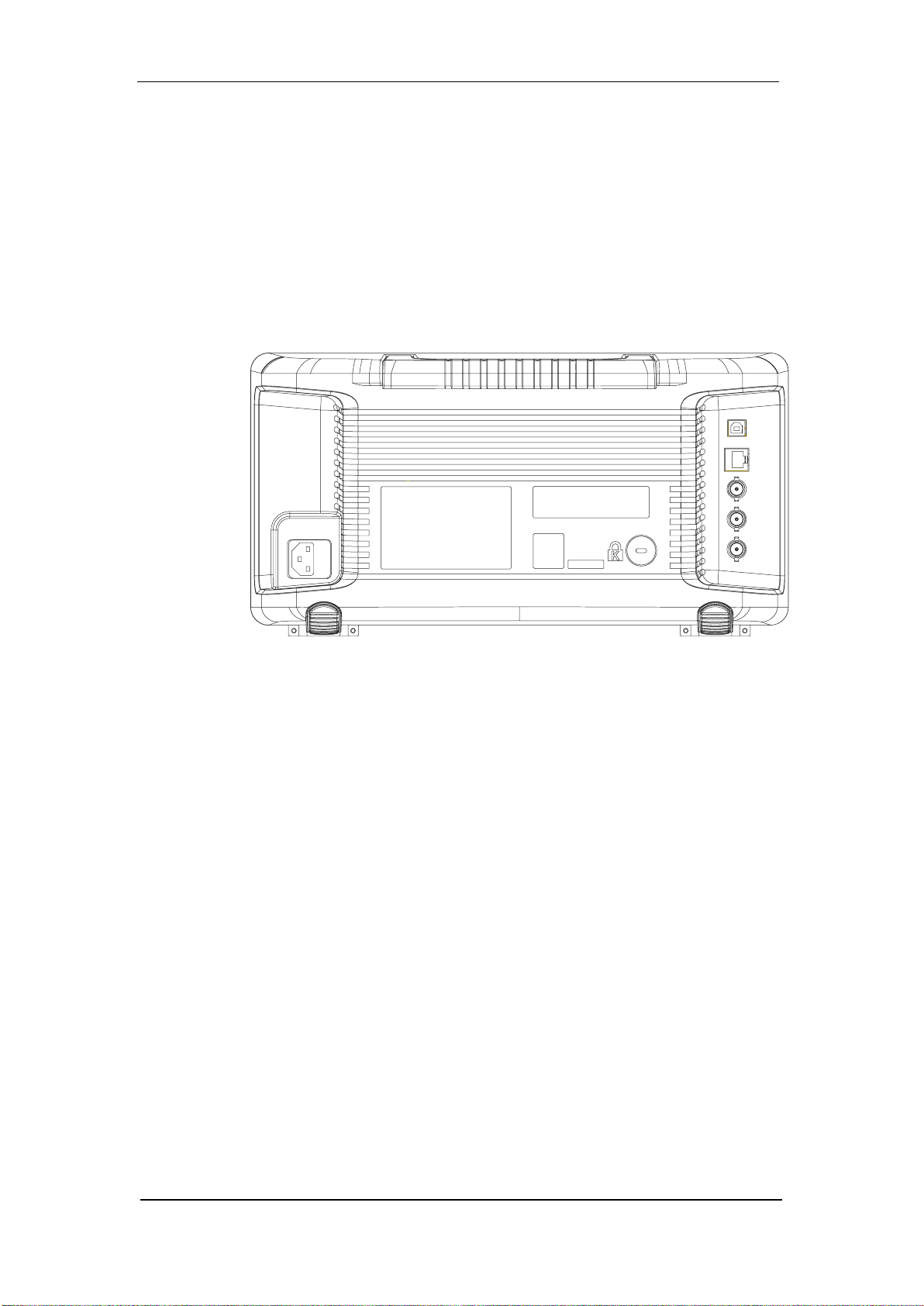
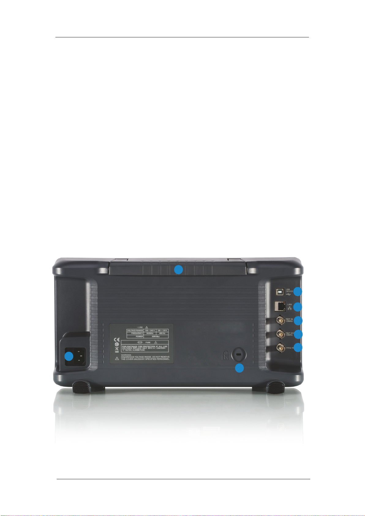
Rear Panel
5
1
4
2
3
7
8
6
1. Handle
2. USB Device
3. LAN Interface
4. 10MHz Reference In
5. 10MHz Reference Out
6. External Trigger In
7. Kensington Lock Point
8. AC Power Socket

1. Handle
Pull up the handle vertically for easy carrying of the instrument. When you do
not need the handle, press it down.
2. USB Device Interface
The analyzer can serve as a “slave” device to connect external USB devices.
Through this interface, a PC can be connected to control the analyzer remotely
through programming or PC software.
3. LAN Interface
Through this interface, the analyzer can be connected to your local network for
remote control.
4. REF IN 10 MHz
The analyzer can use internal or external reference source.
• When a 10 MHz external clock signal is received through the [10 MHz IN]
connector, this signal is used as the external reference source and “Ext Ref” is
displayed in the status bar of the user interface. When the external reference
is lost, transnite or not connected, the instrument switches to its internal
reference source automatically and “Ext Ref” on the screen disappears.
• The [10 MHz IN] and [10 MHz OUT] connectors are usually used to build
synchronization among multiple instruments.
5. REF OUT 10 MHz
The analyzer can use internal or external reference source.
• When internal reference source is used, the [10 MHz OUT] connector can
output a 10 MHz clock signal generated by the analyzer. This signal can be
used to synchronize other instruments.
• The [10 MHz OUT] and [10 MHz IN] connectors are usually used to build
synchronization among multiple instruments.
6. Trigger in
In external trigger mode, the connector receives an external trigger signal
through a BNC cable.
Quick Start 10

7. Security Lock Hole
If needed, you can use a security lock (sold separately) to lock the analyzer to
a desired location.
8. AC Power Supply and Fuse
The analyzer accepts 100-240V, 50/60/400Hz AC power supply. Please use
the power cord provided to connect the instrument. Before power on, make sure
the analyzer is protected by fuse.
Graphical User Interface
41
38
36
34
42
40
39
37
35
33
32
31
30
29
28
27
2
3
26
4
1
2425
5
6 7
8
9
23
10 11
12 131514 16
43
44
45
20
2122
18
17
19
11 Quick Start

Number Name Description
1 Display Area Waveform display area
2 Ref Reference level
When the sweep time less than the auto
3 UNCAL
couple time, the measure result may be
inaccuracy, appear “UNCAL”
4 EXT REF
Ext 10 MHz reference clock detected indicator
5 Att Attenuator Value
6 Day and time System time
7 Pass/Fail status Limit Pass / Fail status
8 Marker Current active marker
9 Trace Active trace
10 Marker Current marker, select to open a new marker
11 Marker X value Frequency, frequency delta or time
12 Operation status Waiting for trigger or acquiring
13 Marker Y value Amplitude value or amplitude delta value
14 USB Storage
15
Main menu
touch icon
USB storage device identication is displayed
when a USB ash drive is inserted
Selecting this button will bring up the main
menu
16 Menu title Function of the current menu
17 Menu selection Menu items of the current function
18
19
Local / remote
status
Sweep progress
indicator
Local is local mode, Remote is remote mode,
Upgrade means the instrument is upgrading
Indicates the currently scanned frequency
position
20 Stop frequency Sweep stop frequency value
21 Sweep time The time a sweep will take
22
Center
frequency
Center frequency value
23 Span Frequency span value
24 VBW Video bandwidth value
25 Start frequency Sweep start frequency value
26 RBW Resolution bandwidth value
Quick Start 12

Number Name Description
When displayed indicates that VBW and RBW
27 Blue icon
are not automatically coupled but in manual
conguration mode
Click to open the commonly used functions for
28 Touch assistant
measurement, such as peak search.
Touch Assist can be moved to any position on
the screen and it can be turned o
Set the trace parameters of A/B/C/D.
Trace mode:
C&W: Clear Write,
MaxH: Maximum Hold,
MinH: Minimum Hold,
View: View,
29, 30, 31,
32
Trace Status
AVG: Video average and times.
Detect Type:
P-PK: Positive peak,
N-PK: Negative peak,
Samp: Sample,
Norm: Normal,
AVG: Average,
Q-PK: Quasi-peak
33 Correction
Indicates that there is a user congured
amplitude correction when present.
34 AM or FM AM or FM identication
35 PA Enable or disable the Preamplier
36 FFT Sweep mode is FFT
37
Single or
Continue
Sweep mode is Single or Continuous
38 Average type Log power / Power / Voltage power
39 Trigger type Free / Video / External trigger
40 Ref oset Reference Oset identication and value
41 Scale / Div Vertical scale value
42 Scale type Log or linear
43 Limit line Limit Pass / Fail level
44 Trigger level Video trigger level
45 Display line Reference display line
13 Quick Start

Mode
The vector network analyzer oers a variety of operating modes, some only
available via user purchased options. Selecting via the Mode key enables:
• Vector Network Analyzer
• Modulation Analysis (AMA/DMA)
• Spectrum Analyzer
• Distance To Fault (DTF)
Front panel key operations vary functionality in dierent modes.
User Notices and Warnings
RF Input
!
Ensure that the input signal to the RF input port does not
contain more than 50 Volts DC, otherwise damage will
occur to the instrument. The AC (radio frequency) input
signal component should not exceed a maximum
continuous power level of +30dBm.
The RF INPUT can be connected to the device under test through a cable with
a N male connector.
In VNA mode this port is used as the input port S21.
Tracking Generator Output
To avoid damage to the tracking generator, The reverse
DC voltage must not exceed 50V DC.
The TG SOURCE can be connected to the device under
test through a cable with a N male connector.
In VNA mode this port is used as the single port of S11 and the VNA output port
of S21.
Quick Start 14

More Information
You can view your instrument model, serial number, hardware and software
version by selecting System → System Info.
For more information about this product, please refer to the following documents:
Vector Network Analyzer User Manual: provides detailed information about
the functions of this product.
Vector Network Analyzer Datasheet: provides the main characteristics and
specications of this product.
Firmware Operation
Check System Information: Users can get the system information by pressing
System→ System Info, including
• Product Model, Serial Number and Host ID.
• Software Version and Hardware Version.
• Option Information.
Firmware Upgrade: Follow this procedure to nish the rmware update:
1. Download the rmware package from the Teledyne LeCroy website
(http://teledynelecroy.com).
2. Extract and copy the .ADS le into the root directory of a USB stick.
3. Plug the USB stick into the USB Host connector. Press System→ System
Info → Firmware Update, nd the .ADS le in USB stick.
4. Press the Load, the analyzer will perform the update process automatically.
The upgrade procedure will take several minutes. Once the upgrade is
completed, please follow the instruction to reboot.
Any interruption during the update process will result in update failure and system
data lost. Do not remove the USB storage device until the update is nished.
15 Quick Start

Loading Options: Refer to the procedures below to activate the options you
have purchased.
1. Press System → Load Option
2. Enter the license key in the onscreen window. Press Enter to conrm your
input and terminate the license key input.
The option will be enabled after rebooting.
Touch Screen Operation
The Vector Network Analyzer has a 10.1 inch touch screen and supports various
gesture operations. Including:
• Click on the upper right corner of the screen to enter the main menu
• Swipe up and down or left and right in the waveform area to change the X-axis
center coordinate or Y-axis reference level
• Perform two-points scaling in the waveform area to change the X-axis span
• Click on a screen parameter or menu for parameter selection or editing
• Open and drag the marker
• Use auxiliary shortcuts to perform common operations
You can turn the touch screen function on and o via Display → Touch Settings
Remote Control
The vector network analyzer supports communication with computers via USB
and LAN. By using these interfaces, in combination with programming languages
and/or NI-VISA software, users can remotely control the analyzer based on SCPI
(Standard Commands for Programmable Instruments) command set, Labview
and IVI (Interchangeable Virtual Instrument), to inter-operate with other
programmable instruments. You can also remote monitor and control the
analyzer in a Web Browser.
For more details, refer to the T3VNA Programming Guide.
Quick Start 16

Using Built-in Help
The built-in help system provides information about every function key at the
front panel and every menu soft key.
• Press Help and a prompt about how to obtain help information will be shown
at the center of the screen. Then, press the key for which you need help and the
relevant help information will be shown at the center of the screen.
• To close the help information window, press Help again.
Figure 11 Help Information.
17 Quick Start

This page is intentionally blank.

This page is intentionally blank.

ABOUT TELEDYNE TEST TOOLS
Company Prole
Teledyne LeCroy is a leading provider of oscilloscopes, protocol analyzers and related test and measurement
solu�ons that enable companies across a wide range of industries to design and test electronic devices of all types.
Since our founding in 1964, we have focused on crea�ng products that improve produc�vity by helping engineers
resolve design issues faster and more eec�vely. Oscilloscopes are tools used by designers and engineers to
measure and analyze complex electronic signals in order to develop high-performance systems and to validate
electronic designs in order to improve �me to market.
The Teledyne Test Tools brand expands on the Teledyne LeCroy product portfolio by adding a comprehensive range
of test equipment solu�ons for its customers. The new range of product solu�ons deliver engineers with a broad
range of quality test solu�ons that enables speed to market product valida�on and design. More and more
designers, engineers and lecturers are relying on Teledyne Test Tools to meet their tes�ng, educa�on and
electronics valida�on needs with condence and within budget.
Loca�on and Facili�es
Headquartered in Chestnut Ridge, New York, Teledyne Test Tools and Teledyne LeCroy have sales, service and
development subsidiaries in the US and throughout Europe and Asia. Teledyne Test Tools and Teledyne LeCroy
products are employed across a wide variety of industries, including semiconductor, computer, consumer
electronics, educa�on, military/aerospace, automo�ve/industrial, and telecommunica�ons.
Test Equipment Depot - 800.517.8
TestEquipmentDepot.com
932657-00 RevA
431 - 5 Commonwealth Ave, MA 01801
 Loading...