

Teledyne Laars Hi-E EPH 300 User Manual
Page 1
Hi-E Model EPH Pool and Spa Heater
SECTION 1.
General Information
This manual provides maintenance instructions for the
T eledyne Laars Hi-E Model EPH 300 pool and spa heater .
SECTION 2.
Overall Operation and Service
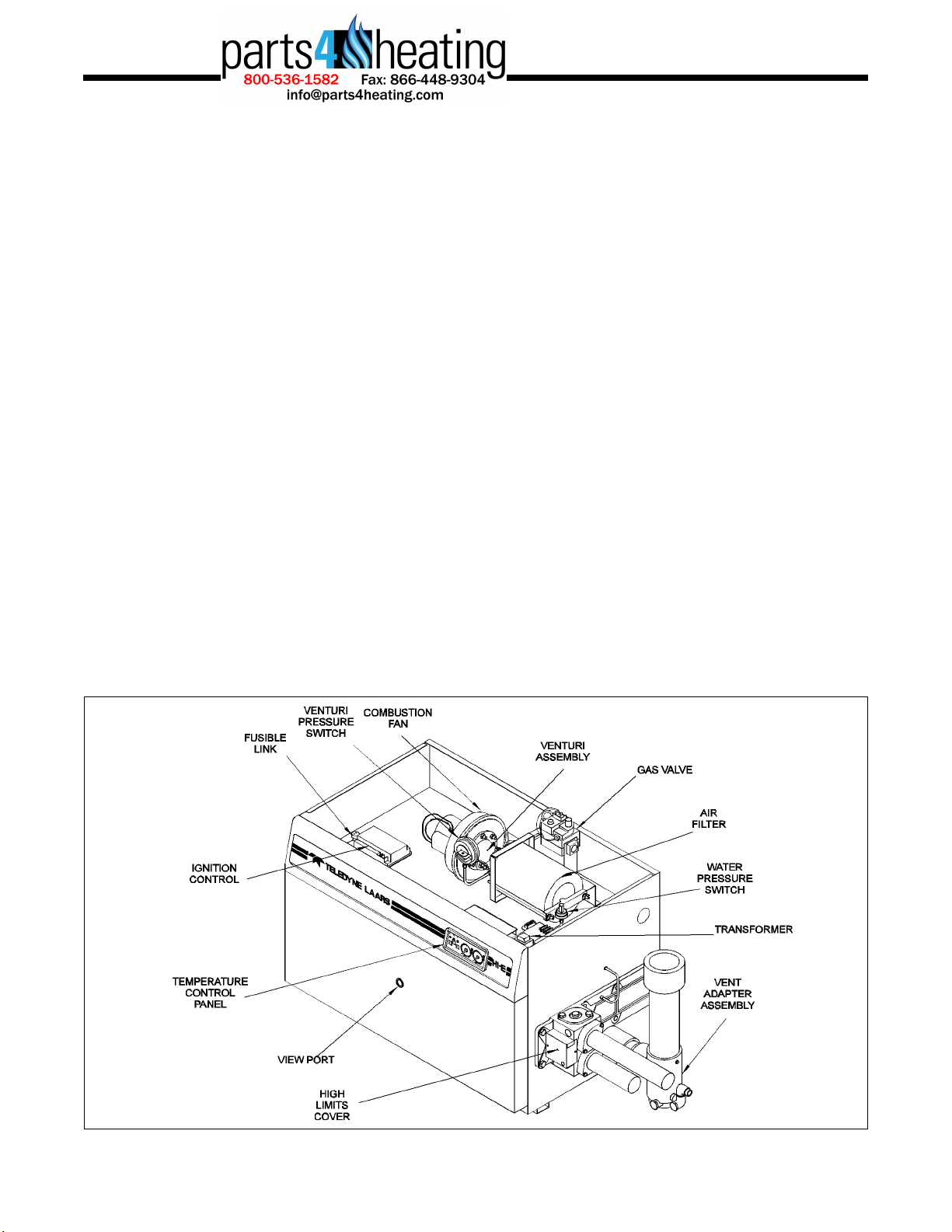
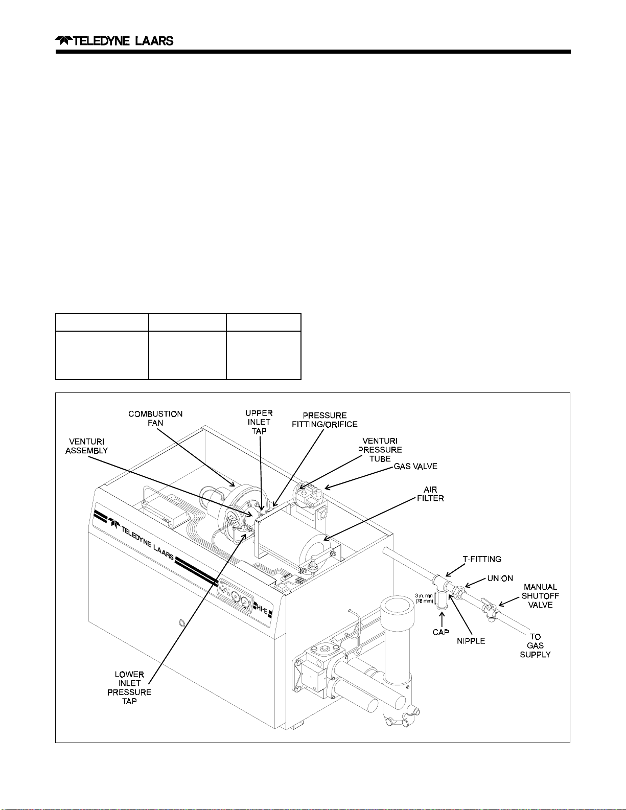
2A. Heater Control Components
Some of the heater control components are the same
as those used in conventional heaters, but others are
designed specifically for the Hi-E EPH 300 heater (see
Fig. 1).
The following paragraphs describe the special
controls and their operation.
2A-1. Pressure Switch
The pressure switch is a safety device that senses
water pressure or back pressure between the heater and
the pool or spa when the filter pump is operating. The
switch is factory set at 2 pounds per square inch (psi)
(14 kilopascals [kPa]).
When the switch senses adequate water pressure, it
closes, allowing the heater to fire. The switch opens any
time water pressure is below 2 psi (14 kPa) and remains
opens, preventing the heater from firing, regardless of
the temperature control setting. If the water pressure is
too high, the switch remains closed, allowing the
heater to fire even if the filter pump is off. Therefore,
the height difference between the heater and the pool or
spa water surface level must fall within the correct
range.
2A-2. High Limit Switches
The Hi-E heater has two disk-type high limit
switches to meet ANSI safety requirements. The high
limit switches open if the temperature of the water
exceeds the respective limits, shutting down the heater.
The high limit switches close and automatically reset
when exposed to cool water flow for a short time.
The 150 degrees Fahrenheit (°F) (66 degrees
Celsius [°C]) high limit switch senses the temperature
of the hottest water as it leaves the heat exchanger .
The 135°F (57°C) high limit switch senses the temperature of the mixed water after it leaves the heater
and mixes with water that bypasses the heater inlet to
the outlet.
Water can overheat if the water flow rate drops,
usually due to a flow restriction in the heat exchanger,
pool piping system, or a dirty filter. A broken disc or
spring in the automatic flow control valve can cause
the 150°F (66°C) high limit switch to open, allowing
too much water to bypass the heat exchanger, correspondingly lowering the water flow rate through the
heat exchanger.
Figure 1. Component Location
Page 2
2A-3. Fusible Link
This is a one-time, thermally fusible element which
shuts down the heater if it detects temperatures higher
than 305°F (152°C) inside the heater control compartment.
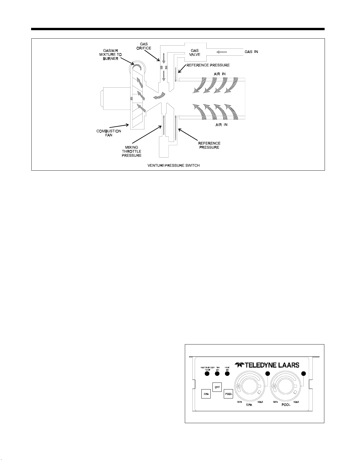
2A-4. Temperature Control Panel
The temperature control panel includes two
temperature controls (regulates pool/spa water temperatures) and a touch pad (OFF, SPA, and POOL)
that turns the heater on and off and selects which
temperature control will be active. An indicator light
above the controls tells you which is active. The
control panel also has lights labeled, WATER BELOW
TEMP, HEAT ON, and FAN ON. These lights indicate the operating status of the heater.
2A-5. Venturi Pressure Switch
The venturi pressure switch senses pressure
through the venturi. Blockage in venting or the heat
exchanger will cause the venturi pressure switch not to
close. The venturi pressure switch is pre-set at the
factory for normal installations. Do not adjust the
venturi pressure switch.
2A-6. Ignition Control
The ignition control provides power to the igniter
and fan, opens the gas valve when there is a call for
heat, and senses when a flame is established. The
ignition control is programmed to make three attempts
at ignition. Each attempt consists of the following
cycle:
1. A 15-second purge period during which the
combustion fan purges the combustion chamber .
2. A 20 to 35-second igniter heat-up period. The
glow of the igniter can be seen through the heater
view port near the end of this period.
3. A 7-second trial for ignition. The gas valve opens
and gas ignites. The gas valve stays open as long
as the igniter senses flame.
If ignition is not successful, the control shuts down
and locks out. It remains in the lockout condition until
the heater is turned off then back on by the touch panel
pads or when the 120 volt alternating current (VAC)
power to the heater is interrupted.
2A-7. Gas Valve
The Hi-E heater has a negative pressure gas valve
that regulates the gas to the heater based on the
amount of air flow through the venturi. The gas valve
is the ON/OFF device that permits gas to flow from
the supply line into the heater. It is ener gized by the
ignition control.
2A-8. Transformer
The transformer converts 120VAC into 24VAC
used by the heater circuit.
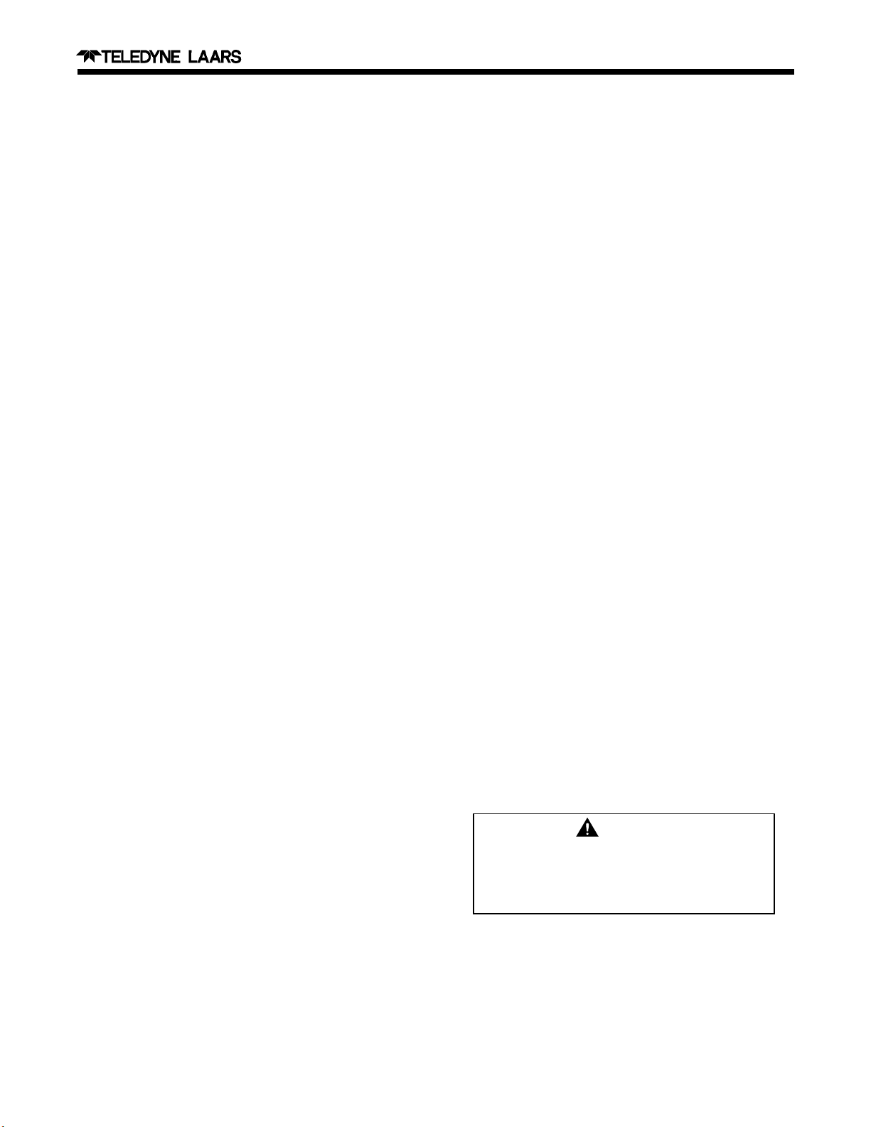
2B. Venturi/Negative Pressure Regulator
System
The fuel/air mixing system in the Hi-E EPH 300
heater makes sure the fuel/air ratio remains the same
under a wide range of flow conditions (see Fig. 2).
An important feature of the pressure system is that
blockage of the combustion air supply or the vent will
only reduce the firing rate; it will not cause poor
quality combustion.
2C. Pressurized Combustion System
The Hi-E EPH 300 heater has a positive pressure
combustion system; the pressure in parts of the system
is slightly higher than atmospheric pressure. This has
an important effect on service procedures. There can
be NO gas leaks in the system from whatever cause. If
a leak exists in the section between the combustion fan
and the burner, a flammable mixture of fuel gas and
air can escape. A leak in the combustion chamber will
release very hot gases. These gases may enlarge the
leak due to their high temperature. Leakage from the
system at points after the heat exchanger will release
combustion products or condensate water. The service
technician must be alert to these possibilities when
servicing the heater.
WARNING
Improper installation or maintenance can
cause nausea or asphyxiation from carbon
monoxide in flue gases which could result in
severe injury, property damage, or death.
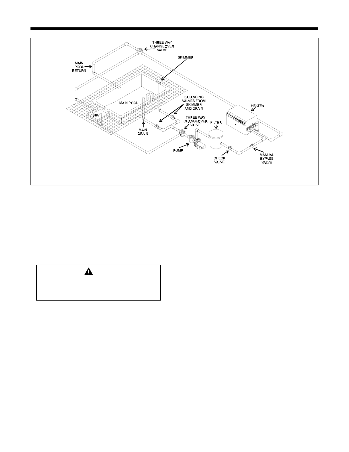
2D. Periodic Inspection
Before starting troubleshooting procedures,
inspect the pool or spa system for obvious problems.
All of the pool system components, including pump,
Page 3
Figure 2. Venturi/Negative Pressure Regulator System
Hi-E Model EPH Pool and Spa Heater
filters, and strainers, water valves, gas supply , electrical power and time clocks, have an effect on heater
operation. The following basic checks should be
performed:
1. Is electrical power to the heater turned on?
2. Is there a time clock or other control in the system,
and is that control on?
3. Is the heater turned on at the touch panel? If it is,
the light over the active temperature control will
be lit.
4. Is the temperature control knob set high enough to
call for heat?
5. Is the gas supply turned on at all locations?
6. Is the heater’s combustion air filter clean?
7. Are all wiring connections solid?
2E. Temperature Rise Test Procedure
A temperature rise test confirms proper water flow
through the heater. Perform a temperature rise test as
follows:
1. Verify the heater is OFF. If it is necessary to turn
the heater off, push the OFF button at the touch
pad (see Fig. 3) and wait at least 3 minutes.
2. Turn the filter pump OFF.
3. Remove the 1/4 inch (6.35 millimeters [mm])
National T aper Pipe (NPT) plug located on the
inlet/outlet header (see Fig. 4) and replace it with a
Pete's plug.
4. Insert a pocket thermometer through the Pete's
plug into the header to a depth of about 5 inches
(127 mm).
8. Is the ignition control in lockout mode? Turn the
heater off and then back on at the touch panel to
restart the ignition sequence.
If all of these items have been checked, look for
less obvious problems (see Section 3, Troubleshooting).
Figure 3. Temperature Control
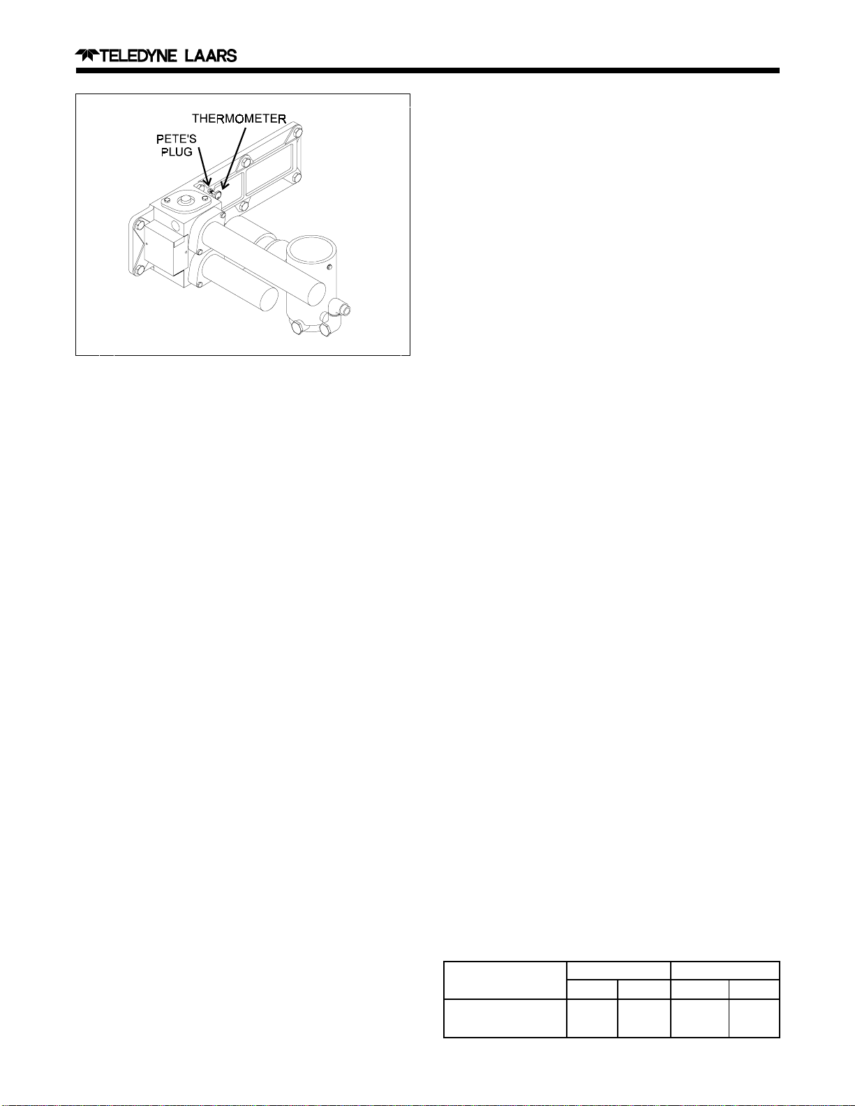
Figure 4. Thermometer Location
5. Make sure the pool filter is clean.
6. Close manual bypass valve, if installed.
7. Turn the filter pump ON and wait 5 minutes.
8. Record the temperature indicated by the thermometer (cold water).
9. Turn the heater on following the lighting instructions found under the top panel of the heater.
10. Allow the heater to run for 5 minutes. Record the
new temperature reading (hot water).
11. Subtract the first temperature reading (cold water)
from the second temperature reading (hot water).
The difference between the two readings is called
the temperature rise. Proper water flow rate is
obtained when the temperature rise falls between
18 and 22°F (10 and 12.2°C).
12. If the temperature rise is within the correct range
(see step 11), complete the procedure as follows:
Page 4
If the temperature rise is outside the range indi-
cated, two possibilities arise:
1. Case 1: The temperature rise value is less than
18°F (10°C).
2. Case 2: The temperature rise value is greater than
22°F (12.2°C).
2E-1. Temperature Rise Test Case 1
There are two conditions that can produce a
temperature rise value less than 18°F (10°C): The
supply gas pressure is too low or the system's water
flow is too high.
Use table 1 to verify the heater's gas supply while
the unit is firing and as close as possible to the unit
under test.
Low supply gas pressures can be the result of
using the wrong pipe size, meter, valves, or regulators.
Correct the problem, then repeat the temperature rise
test.
If the temperature rise is still below 18°F (10°C)
after a retest, then the system's water flow may be too
high.
If the system filter-flow rate is higher than ap-
proximately 125 gallons per minute (GPM) (474 liters
per minute [LPM]), install a manual bypass valve with
an adjustable valve (see Fig. 5). Then repeat the
temperature rise test, gradually adjusting the flow with
the bypass valve (see Section 2D-3) until the proper
temperature rise is obtained. Once the adjustment is
complete, wire the handle of the manual by-pass to the
pipe to prevent any accidental change in the water
flow .
2E-2. Temperature Rise Test Case 2
The main reason for a temperature rise value
greater than 22°F (12.2°C) is a low water flow
through the heater. Check the installation for the
following:
1. Incorrect water pipe size or a combination of
different pipe sizes.
a. Turn the heater off.
b. W ait 5 minutes, then turn the filter pump of f.
c. Remove the thermometer and the Pete's plug.
d. Replace the 1/4 inch (6.35 mm) NPT plug at
the header.
2. Excessive pipe length for the size pump installed.
3. Pump too small for application.
Table 1. Gas Supply Pressure Requirements
Supply Pressure Natural Gas Propane Gas
Water Column in. mm in. m m
Minimum 5 127 11 279
Maximum 10 254 14 356
Page 5
Notes:
1. When using metal pipe as heat sink, join metal and PVC/CPVC, using metal male and PVC/CPVC female connection.
2. A manual bypass valve is used only when filtration rate normally exceeds 125 GPM (474 LPM).
Hi-E Model EPH Pool and Spa Heater
Figure 5. Typical Manual Bypass Valve Installation
4. T oo many restrictions in the water path which may
include small pumps or 2 speed pumps (low), dirty
filters, clogged pipes, or partially closed water
valves to the heater.
Verify and correct the condition and then repeat
the temperature rise test.
Caution
Operation with the temperature rise above
maximum or below the minimum can
damage the heater and will void the warranty.
2E-3. Adjusting the Manual Bypass Valve
After the manual bypass valve is installed, use the
following procedures to set the bypass valve:
1. Close the manual bypass valve completely .
2. Repeat steps 7 through 12 of the temperature rise
test (see Section 2E), slowly opening the manual
bypass until the temperature falls between 18 and
22°F (10 and 12.2°C).
3. Once the temperature is within the correct range,
wire the handle of the manual bypass valve to the
pipe to prevent change in the water flow .
SECTION 3.
Troubleshooting
3A. Supply Gas and Metering System
If the heater does not supply its rated output
(heating too slow), or if a blue lazy flame (too little
gas), or a bright flame (too much gas) is noticed,
check the supply gas pressure. Proper operation of the
fuel/air balancing system depends on the following:
1. Proper supply gas pressure to heater.
2. Correct gas pressure difference across the meter-
ing orifice.
3. Correct orifice for the fuel being used. Figure 3
shows how the system works.
4. V ent pipe length.
3A-1. Checking the Manifold Regulated Gas
Pressure
The Hi-E heater's negative pressure gas valve
regulates the gas to the heater based on the amount of
air flow through the venturi. Proper operation of the
heater depends on the proper settings of the gas flow .
Symptoms of improper operation are either a blue lazy
flame (too little gas) or a bright yellow flame (too
much gas).
Page 6
NOTE: Gas supply test, stack test, and air flow filter
test should be completed before attempting this test or
making any adjustments.
1. Check supply gas pressure (see Section 3B-2).
2. Check that all ports and tubes are clear that
connect the gas valve and venturi.
3. Check for proper orifice (see T able 2).
4. Attach a manometer or a 1/2 inch (13 mm)
negative pressure gauge between the outlet pressure tap on the gas valve and the venturi (lower)
inlet pressure tap (see Fig. 6).
Table 2. Gas Metering Orifice Size
Natural Gas LP Gas
Orifice Diameter 0.354 in. 0.295 in.
(8.99 mm) (7.49 mm)
Color Code Brass Silver
5. The pressure at the gas valve outlet will be 0.2
inch (5.08 mm) water column (W .C.) less than the
pressure at the venturi (lower) inlet.
6. T ake a reading. The ideal range should be between
-0.1 and -0.3 inches (-2.5 and -7.6 mm) W.C.
when the gas valve is energized.
IMPORT ANT: Before the gas valve is energized, the
pressure reading will be approximately 2.8 inches (71
mm) W .C. on outdoor units fitted with the standard
vent stack. On indoor installations with vent piping as
long as 60 feet (18 meters [m]), the pressure can be as
low as 2.0 inches (51 mm) W.C.
3A-2. Checking the Supply Gas Pressure
T o check the gas supply pressure:
1. Attach one end of a manometer hose to the fitting
on the gas valve (see Fig. 6).
2. Remove threaded cap from T-fitting and replace
with fitting from manometer.
Figure 6. Checking the Gas Pressure
 Loading...