

Teledyne ISCO CombiFlash Torrent User Manual

CombiFlash Torrent®
User Manual
For Indoor Use Only
Part #60-5243-135
Revision H, February 16, 2021
COPYRIGHT © 2021 by Teledyne ISCO

1-2

Teledyne Isco One Year Limited Factory Service Warranty*
This warranty exclusively covers Teledyne Isco
instruments, providing a one-year limited warranty
covering parts and labor.
Any instrument that fails during the warranty period due to
faulty parts or workmanship will be repaired at the factory
at no charge to the customer. Teledyne Isco’s exclusive
liability is limited to repair or replacement of defective
instruments. Teledyne Isco is not liable for consequential
damages.
Teledyne Isco will pay surface transportation charges both
ways within the 48 contiguous United States if the
instrument proves to be defective within 30 days of
shipment. Throughout the remainder of the warranty period,
the customer will pay to return the instrument to Teledyne
Isco and Teledyne Isco will pay surface transportation to
return the repaired instrument to the customer. Teledyne
Isco will not pay air freight or customer’s packing and
crating charges. This warranty does not cover loss, damage,
or defects resulting from transportation between the
customer’s facility and the repair facility.
The warranty for any instrument is the one in effect on date
of shipment. The warranty period begins on the shipping
date, unless Teledyne Isco agrees in writing to a different
date.
Excluded from this warranty are normal wear; expendable
items such as desiccant, pH sensors, charts, ribbon, lamps,
tubing, and glassware; fittings and wetted parts of valves;
check valves, pistons, piston seals, wash seals, cylinders,
pulse damper diaphragms, inlet lines and filter elements;
and damage
due to corrosion, misuse, accident, or lack of
proper
installation or
maintenance. This warranty does not
cover products not sold under the Teledyne Isco
trademark or for which any other warranty is specifically
stated.
No item may be returned for warranty service without a
return authorization number (RMA) issued by Teledyne
Isco.
This warranty is expressly in lieu of all other warranties
and obligations and Teledyne Isco specifically disclaims
any warranty of merchantability or fitness for a
particular purpose.
The warrantor is Teledyne Isco, 4700 Superior, Lincoln, NE
68504, U.S.A.
*This warranty applies to the USA and countries where Teledyne Isco does not have an authorized dealer.
Customers in countries outside the USA, where Teledyne Isco has an authorized dealer, should contact
their Teledyne Isco dealer for warranty service.
Problems can of t e n be diagnosed and corrected without returning the instrument to the
factory. Before returning any instrument for repair, please contact the Teledyne Isco Service
Department for instructions and to obtain a return material authorization number (RMA).
Instruments needing factory repair should be packed carefully and shipped to the attention of
the service department. Small, non-fragile items can be sent by insured parcel post. PLEASE
WRITE THE RMA NUMBER ON THE OUTSIDE OF THE SHIPPING CONTAINER and
enclose a note explaining the problem.
Shipping Address: Teledyne Isco - Attention Repair Service
4700 Superior Street
Lincoln, NE 68504 USA
Mailing Address: Teledyne Isco
PO Box 82531
Lincoln, NE 68501 USA
Phone: Repair service: (800) 775-2965 (lab instruments)
(866) 298-6174 (samplers & flow meters)
Sales & General Information: (800) 228-4373 (USA &Canada)
Fax: (402) 465-3001
Email: IscoService@teledyne.com
March 2, 2016 P/N 60-1002-040 Rev J
1-3

1-4

1.1 Documentation Overview
This Installation Guide provides:
• Safety Information
• Unpacking instructions
• Installation instructions, including placing the CombiFlash Torrent module on a
network and direct connections with a computer or hand-held device
• Certification and warranty information.
CombiFlash Torrent
User Manual
Section 1 Introduction
®
Once you are operating the Torrent, you may refer to the Help menu for operati
instructions and further assistance.
Avoid hazardous practices! If you use this instrument in any way not specified in this
manual, the protection provided by the instrument may be impaired; this may increase your
risk of injury.
1.2 Product Overview
The Teledyne ISCO CombiFlash Torrent and Torrent AQ flash chromatography systems give
you high-productivity automation, programmable gradients, UV or UV-Vis detection and
peak separation,
an unattended run under computer control at user selected flow rates between 50 and 1000
mL/min. The Torrent operates up to 100 psi (6.9 bar) and can use low- or medium-pressure
Flash columns for either normal or reversed phase separations. Braided stainless steel 2.75
meter (9 foot) supply lines are supplied with the Torren
solvent level detection features that prevent chromatography runs from running out of
solvent. Samples can be introduced to the Torrent by injecting a liquid sample into the
injection port. Liquid samples can also be pumped into the injection port using the optional
Sample Load Pump. Alternately, liquid samples can automatically be loaded on the Torrent
AQ using t
low-solubility and liquid samples using solid load sample cartridges.
and automatic detection of columns. The Torrent can separate a sample in
he integrated sample load line on the solvent select valve. The Torrent can load
ng
WARNING
t. These supply lines support the
Column eluate passes through the UV or UV-Vis detector which can trigger collection of peak
fluids. The system also accepts an input signal to cut peaks using an external detector such
as an ELSD instrument. The Torrent can control a Foxy R2 High Flo
Fractionation Valve to isolate the fluid in vessels.
Applications include development-scale purification of organic compounds for drug discovery
and chemical research, as well as scale-up production for agrochemicals, petrochemicals,
natural products, polymers, and catalysts.
w fraction collector or a
1-1
CombiFlash Torrent® User Manual
1.3 Operating Overview
The Torrent is equipped with a touch screen display for local control.
The system supports TCP/IP communication. This allows direct control of the Torrent by a
Windows computer via a cross-over cable between Ethernet ports of the Torrent and the
computer. The Windows computer must have Microsoft Internet Explorer 7 or newer.
TCP/IP communication also allows remote control via
controlling devices on the network can be a Windows PC or an Apple mobile digital device (iPod
Touch, iPhone, and iPad).
N ot Note
Teledyne ISCO recommends that you obtain assistance from your Information Technology
department before attempting direct or network connections to a Windows computer.
1.3.1 Multiple Control Possibilities
The system can be accessed from the built-in touch panel and up to ten network computers. The
touch panel shares control with all connected computers. The system performs the most recent
command fr
om any control input.
1.3.2 File Storage
To support operation from a variety of direct and network connections, the CombiFlash Torrent
stores the software and all files on an internal hard drive. This ensures that your compound
purification methods and run history files can be viewed from any connection. Optionally,
individual run history files may be saved to a USB flash drive and the hard drive o
networked computer, and all run history files can be saved to a network drive.
1.4 Specifications
an established network. Remote
r a
1-2
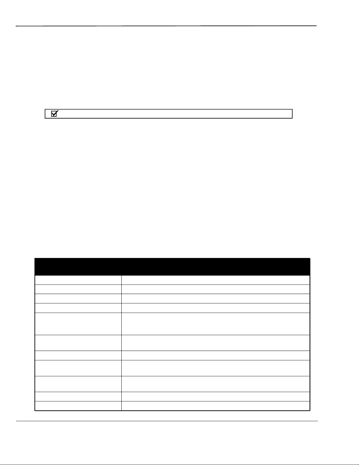
Table 1-1 CombiFlash Torrent Module Specifications
Sample size: 0.5 to 300 grams
RediSep Rf column sizes: 80 gram to 3 kilogram
Flow rate: 50 – 1000 mL/min
2
Maximum pressure
Detection: 200 – 360 nm (200 – 780 nm optional) with single, dual, or
Gradient: Binary, high pressure solvent mixing with linear, step, or isocratic
Gradient accuracy: <2% full scale from 0.2 to 1.0 li
Sample injection: Automated injection with options of solid load cartridges, liquid load, or
Controller: 26.7 cm (10.4 inch) touch screen
Software: On-screen method development and control with PeakTrak software
Fraction collection: Up to four fraction collectors, fractionation valve, or manual collection
: 6.89 bar (100 psi)
All-wavelength Collection.
Accepts external detector input.
capability. Two solvent inlets.
ter/min.
direct injection.
Supports remote control via Windows® PC.
1

Section 1 Introduction
Table 1-1 CombiFlash Torrent Module Specifications
1
(Continued)
Solvent management: Patented, active level sensing for inlet and waste containers
Module dimensions:
(W x D x H)
47 x 43.5 x 71.4 cm
18.5 x 17.9 x 28.1 inches
Module weight: 65 lbs (29.5 kg)
Operating voltage: 100 VAC 50 Hz, 2 amperes
117 VAC 60 Hz, 2 amperes
234 VAC 50 Hz, 1 ampere
(±10% of the region’s nominal line voltage)
Safety and sample securit
y: Static-dissipative tubing throughout,
Vapor sensor for internal leak detection,
Overpressure sensor,
Active solvent and waste level sensing,
Audible alarm when user intervention is required.
Ambient Temperature 20 to 40°C (maximum temperature must be at least 15°C below the
boiling point of the solvent)
Humidity (when connected to
95% relative humidity maximum at 20 to 40°C
power)
Certification: CE
Installation Category II
Maximum Altitude 2000 meters
Pollution Degree 2
Note 1. All specifications are subject to change.
Note 2. For columns undetected by RFID, the max pressure is limited to 50 psi.
1.5 Controls, Indicators, and Features
Figures 1-1 through 1-3 illustrate key features on the Torrent.
1-3
CombiFlash Torrent® User Manual
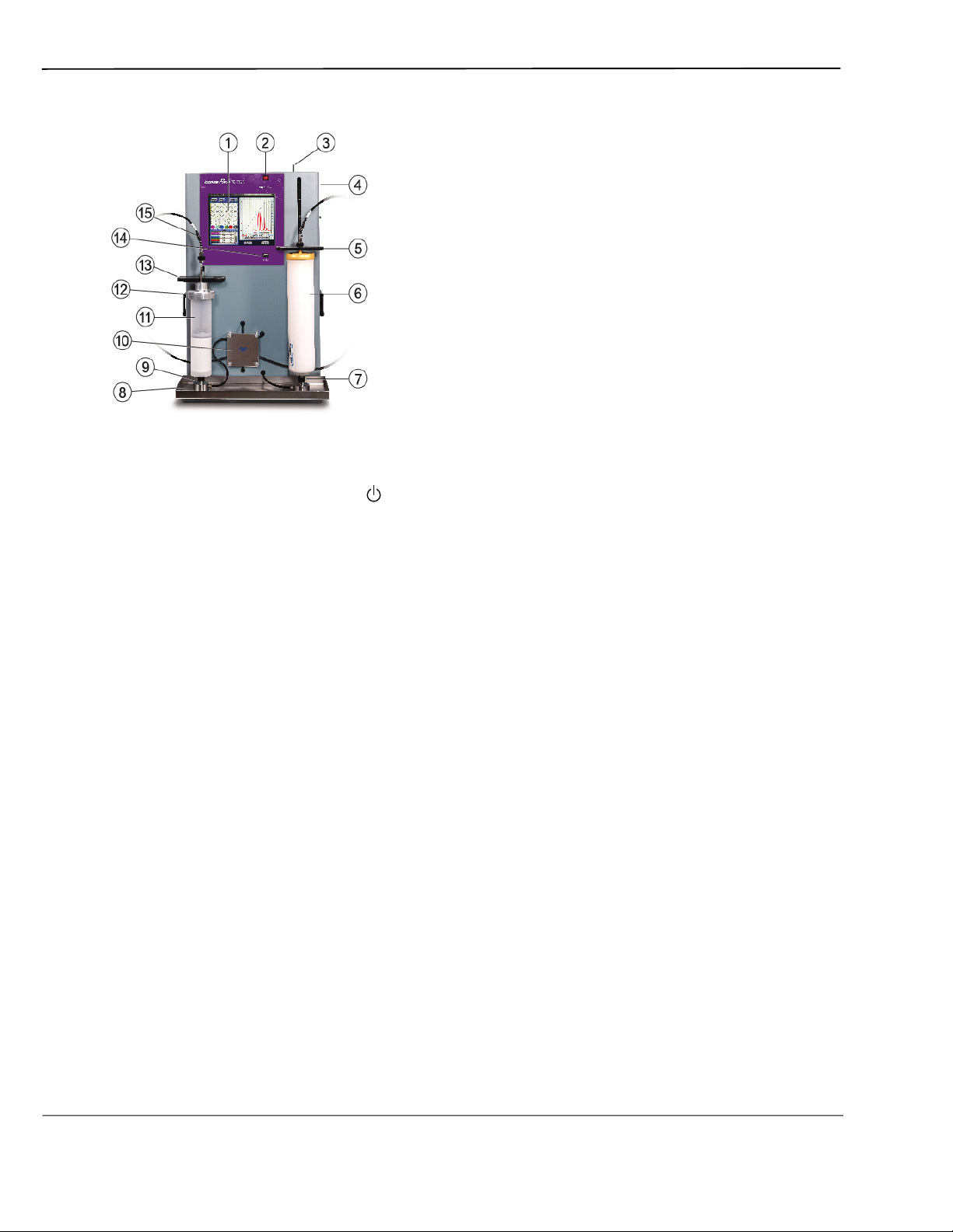
Figure 1-1 CombiFlash Torrent Features (Front)
1. Touch Panel LCD display – Large 10.4 inch display for system monitoring and control.
2. On/Standby Switch – 1 = On, = standby.
3. Upper Column Mount Release – The upper column mount will latch at the top of its
travel to ease column replacements. The latch holds the mount in place until the release is
pushed to the left.
4. To Collector – On right side of instrument, not visible in the image. Eluate that is not
diverted to waste is delivered to this outlet port for collection. Collection may be performed
manually, or automated by a Foxy R2 High Flow
fraction collector or a Fractionation Valve.
5. Upper Column Mount – The column mount holds the column in place and plumbs the
mobile phase to the column inlet through interchangeable fittings that support a variety of
column sizes.
6. Column – The Torrent is designed for use with RediSep® Flash chromatography columns
which include RFID technology for automatic detection.
7. Lower Column Mount – The column mount holds the column in place and plumbs the
column outlet to the internal UV or UV-vis detector.
8. Drip Tray and Drain – Should any leaks occur at the front panel fittings, the drip tray and
drain will carry away the fluids.
9. Sample Injection Port – This fitting accepts the sample though either a solid load sample
cartridge
(shown) or a liquid injection using a sample load pump, syringe, or similar device.
10.Injection Valve – The Torrent automatically positions this valve according to its current
mode of operation. Modes include column equilibration, sample injection, elution, column
flushing, valve cleaning, and air purging.
1-4
11.Solid Load Cartridge – Solid load cartridges are a useful way to load low-solubility
samples onto the column. Cartridges are available filled with silica gel, Celite, and C18
media, or as empty cartridges to be filled with yo
ur media of choice. The cartridge outlet
connects to the sample injection port (9).
Section 1 Introduction
12.Solid Load Cartridge Cap – Adds the cartridge to the fluid path. An internal plunger
minimizes any volume above the bed.
13.Solid Load Cartridge Cap Mount – This spring-loaded mount secures the solid load
cartridge and cap in place.
14.USB Port – Convenient, front panel port that accepts USB Flash memory drive. A Flash
memory drive may be inserted into this port for transferring files, importing and exporting
methods, and Torrent software updates.
15.Solid Load Cartridge Tubing – This tubing connects to the Solid Load Cartridge Cap.
In some configurations, such as a system purge, it can be connected to the Sample Injection
Port. In c
onfigurations without solid load cartridges, the tubing is not used.
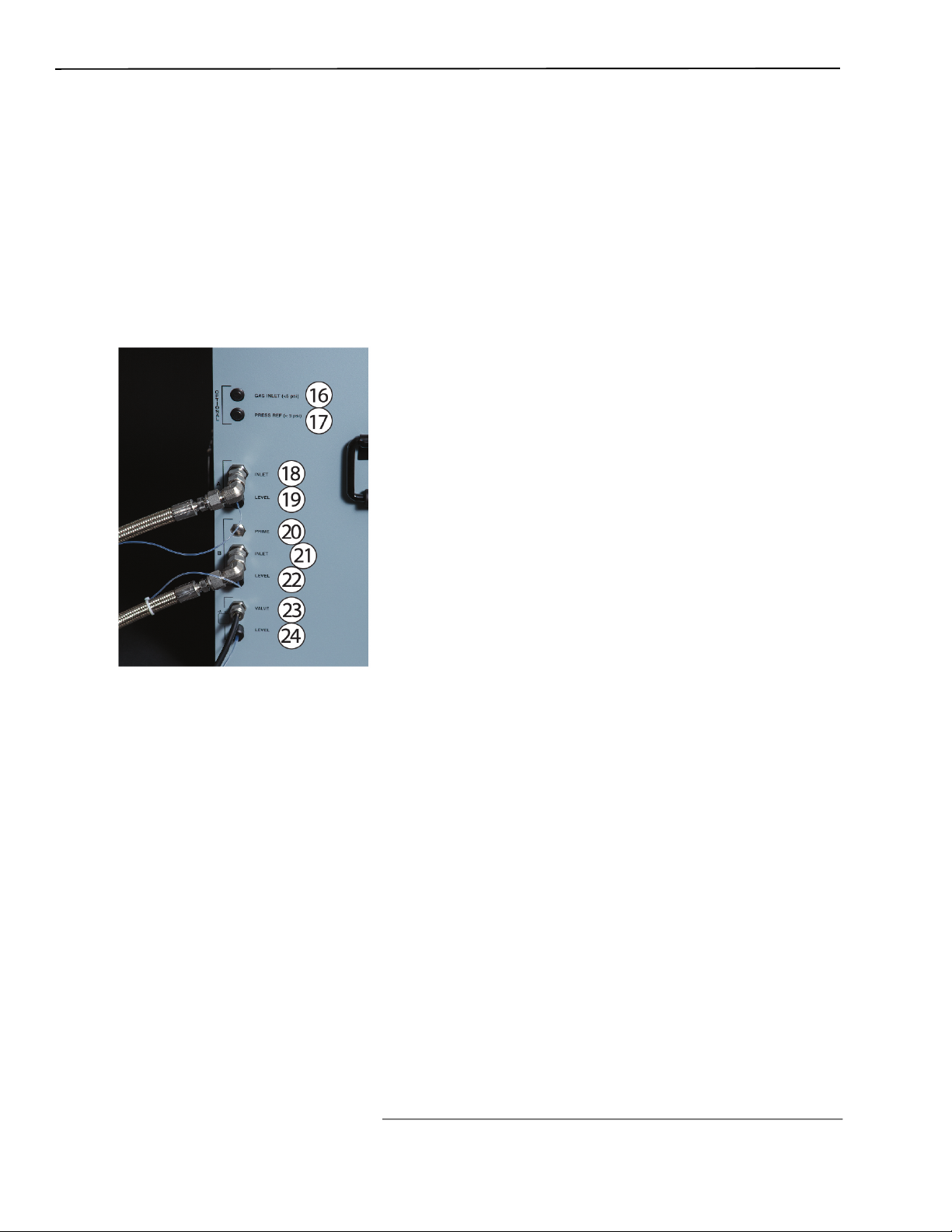
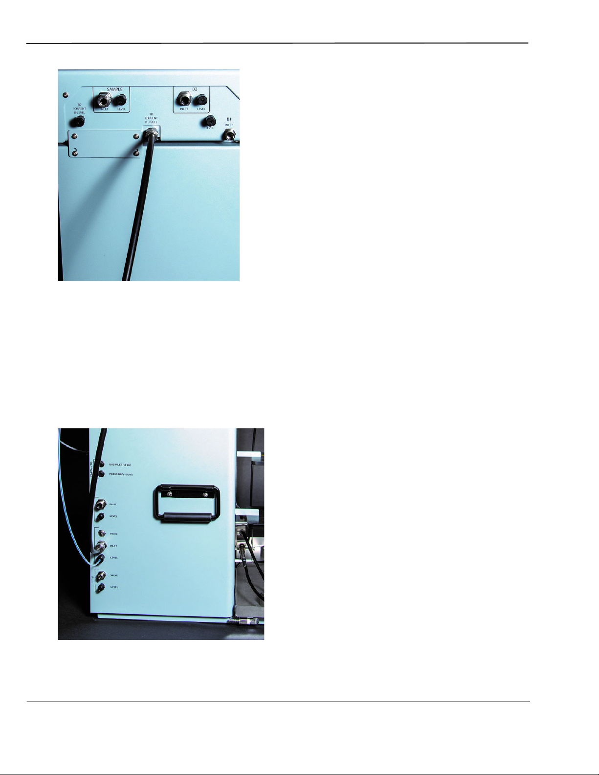
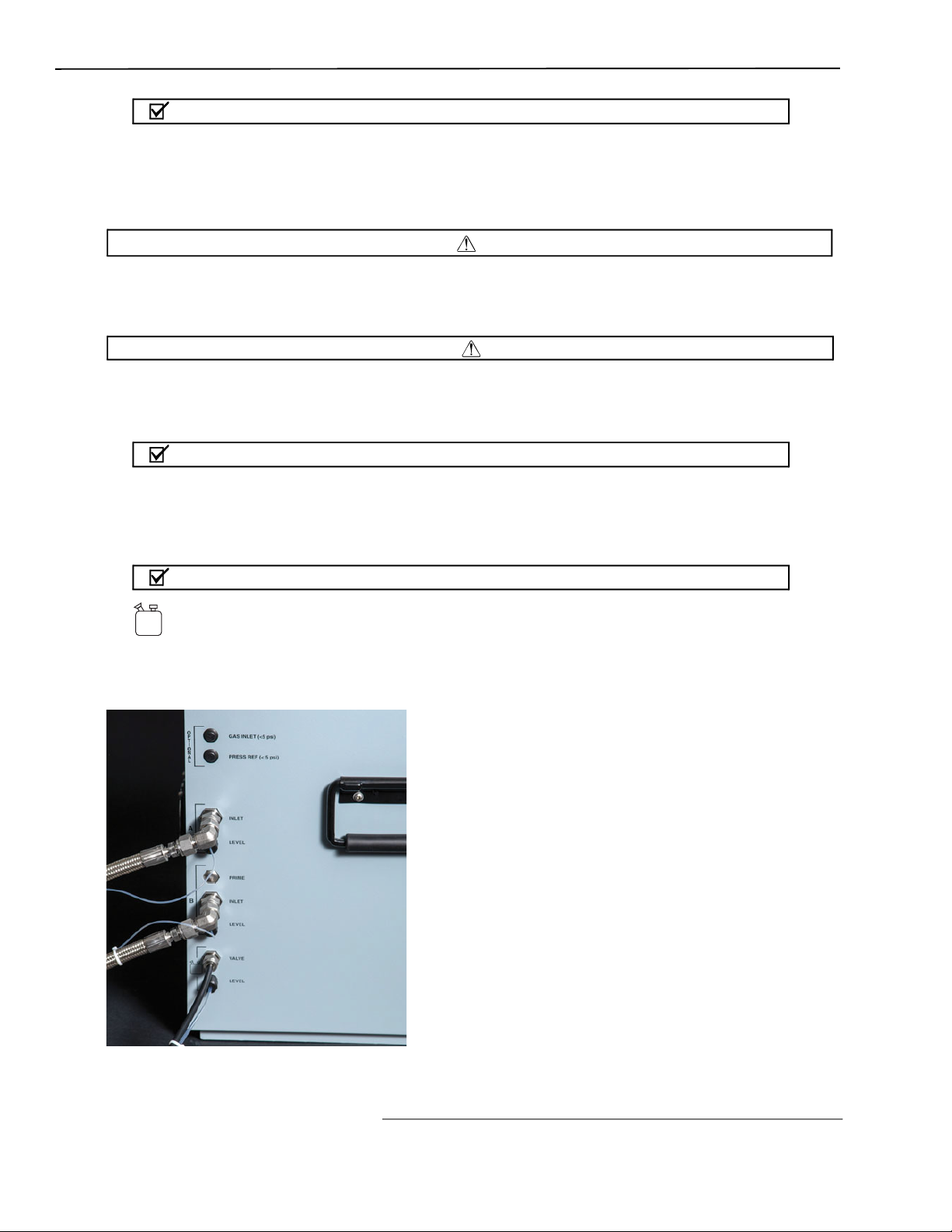
Figure 1-2 CombiFlash Torrent Features (Side, close up)
16.Gas Inlet – The Torrent has an internal air pump that delivers air through the column for
a post-run purge. The air is also used to detect solvent and waste levels. If you desire to use
a specific gas such as nitrogen, connect the gas source to this port.
17.Pressure Reference – When detecting solvent or waste levels in containers or conduits
not exposed to atmospheric pressure, a headspace reference pressure is re
quired so that
the Torrent can read the differential pressure to determine levels.
18.A Inlet – This port receives the A solvent.
19.A Level – This port measures the solvent A level by means of pressurized air or gas
source.
20.B Prime – This port primes the B solvent pump (Torrent only).
21.B Inlet – This port receives the B solvent.
22.B Level – This port measures the solvent B level by means of pressurized air or gas
source.
23.Waste Valve – This port delivers waste fluids to a user-supplied waste container.
1-5
CombiFlash Torrent® User Manual
24.Waste Level – The Torrent uses air or user-supplied gas to measure the hydrostatic
pressure of the waste above the level sense line end. The system will suspend operation
when this user-set level is too high.
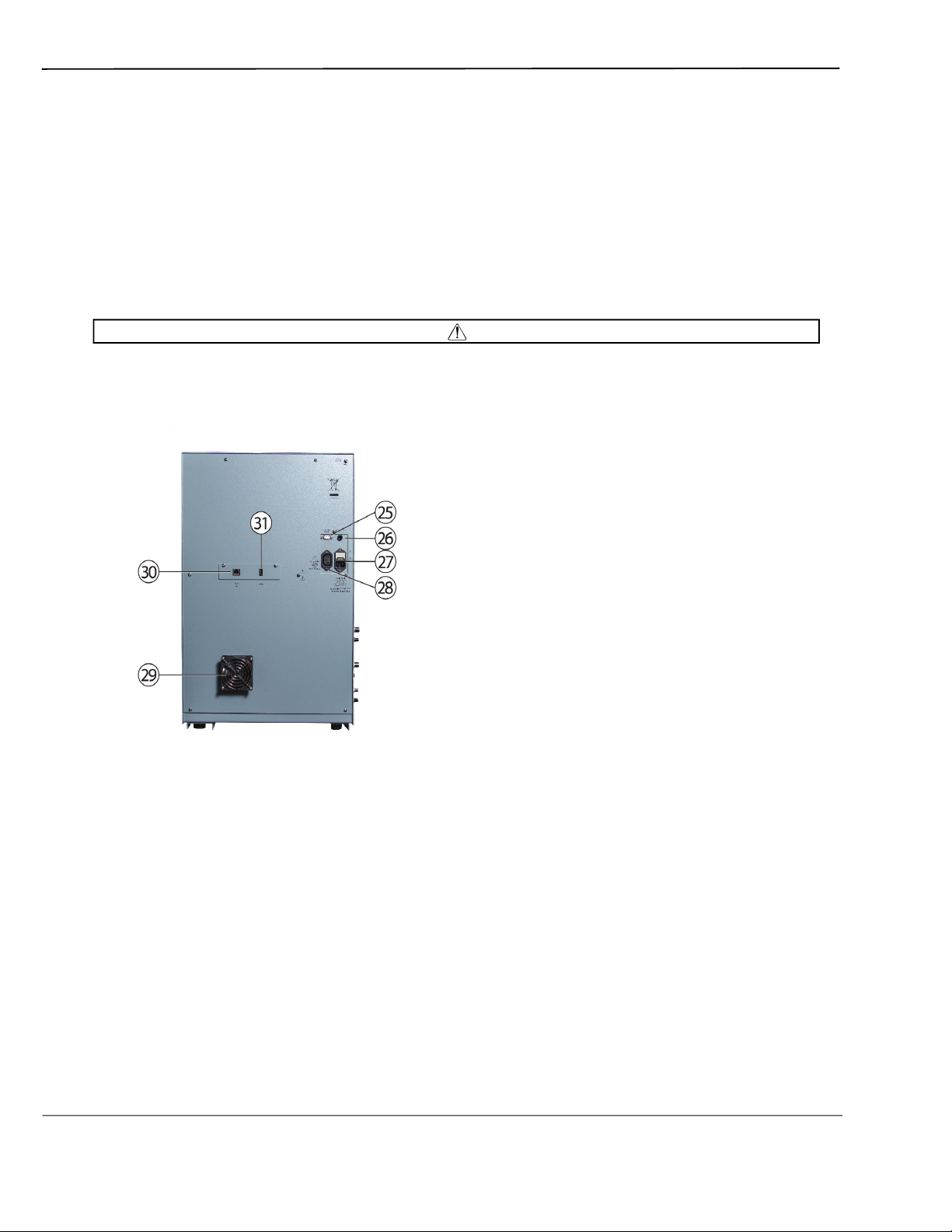
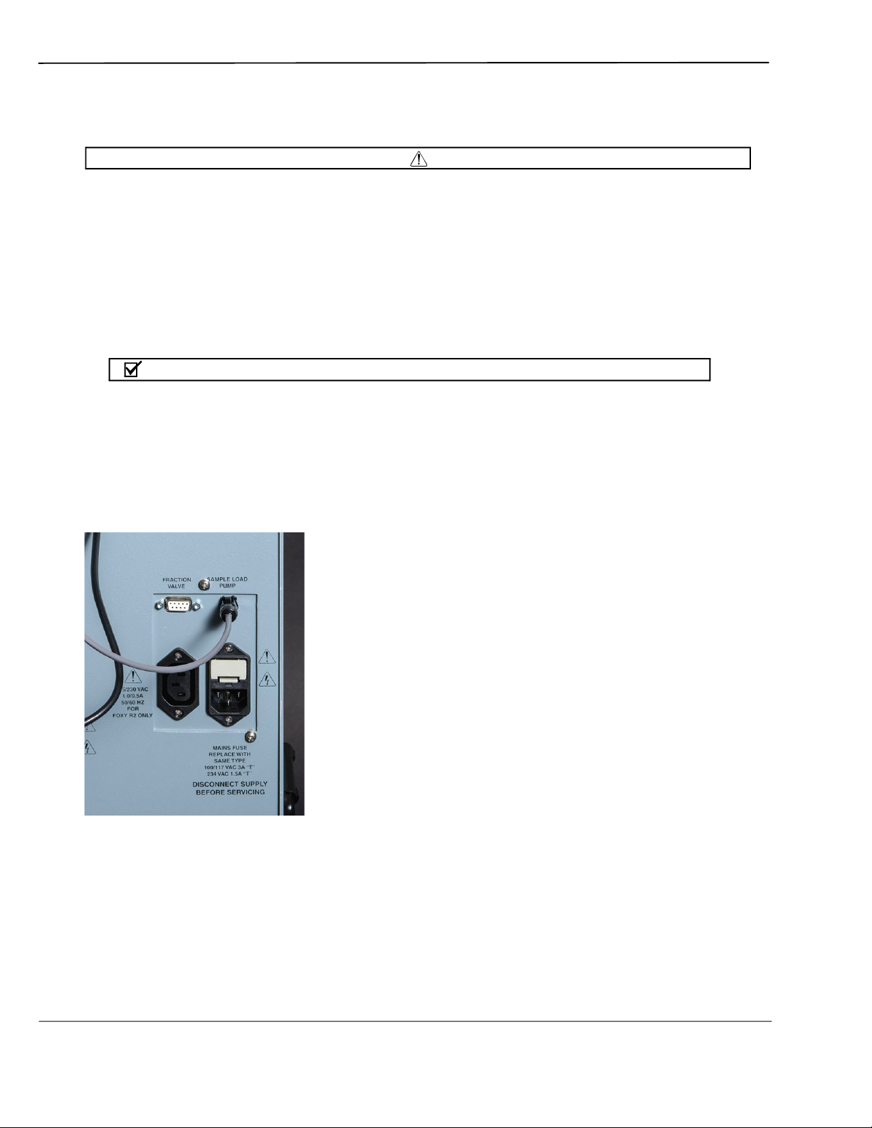
25.Fraction Valve – The Torrent controls the optional Fractionation Valve through this port.
26.Sample Load Pump – The Torrent controls the optional Sample Load Pump through this
port.
27.Mains Power – Connects the Torrent to AC line voltage.
28.Power Outlet – Provides AC line voltage to an external device that meets the 115 VAC and
2.0 ampere or 230 VAC and 1.0 ampere rating.
The back panel power connector is intended only for use with the Foxy R2 fraction collector.
Do not connect other devices to this outlet.
CAUTION
– Figure 1-3 CombiFlash Torrent Features (Back)
29.Cooling Fan – Cools the internal components.
30.Ethernet Port – An 8P8C jack for a network connection using a standard CAT5/6 cable, or
for a direct connection to a computer using a cross-over cable.
31.USB Port – To interface with peripheral devices. This rear panel port is primarily for
service-related functions.
1.6 Safety
Before installing, operating, or maintaining this equipment, it is imperative that all hazards
and preventive measures are fully understood. While specific hazards may vary according to
location and application, take heed in the following general warnings:
1-6

Section 1 Introduction
WARNING
Avoid hazardous practices! If you use this instrument in any way not specified in this
manual, the protection provided by the instrument may be impaired.
WARNING
Liquids associated with this instrument may be classified as carcinogenic, biohazard,
flammable, or radioactive. Should these liquids be used, it is highly recommended that this
application be accomplished in an isolated environment designed for these types of
materials in accordance with federal, state, and local regulatory laws, and in compliance
with your company’s chemical/hygiene plan in the event of a spill.
WARNING
If you are using flammable solvents or chemicals with this system, vapor concentration
levels may exceed the maximum exposure levels as recommended by OSHA Guide
1910.1000. To reduce those levels to a safe exposure, Teledyne ISCO recommends that you
place the system in a laboratory hood designed for the purpose of ventilation. This hood
should be constructed and operated in accordance with federal
In the event of a solvent or chemical spill, your organization should have a plan to deal with
these mishaps. In all cases, use good laboratory practices and standard safety procedures.
state and local regulations.
The CombiFlash Torrent has redundant safety devices to limit pressure to less than 100 psi
(689 kPa). RediSep columns smaller than 100 g are CE certified using standard IEC61010-1
for use on the CombiFlash Torrent. RediSep columns larger than 100 g meet Pressure Vessel
Directive 97/23/EC. Teledyne ISCO strongly recommends against the use of columns rated
less than 100 psi (689 kPa).
1.6.1 Hazard Severity Levels
This manual applies Hazard Severity Levels to the safety alerts. These three levels are
described in the sample alerts below.
Cautions identify a potential hazard, which if not avoided, may result in minor or moderate
injury. This category can also warn you of unsafe practices, or conditions that may cause
property damage.
Warnings identify a potentially hazardous condition, which if not avoided, could result in
death or serious injury.
WARNING
CAUTION
WARNING
1-7
CombiFlash Torrent® User Manual
Limited to the most extreme situations to identify an imminent hazard, which if not avoided,
will result in death or serious injury.
1.6.2 Hazard Symbols
The equipment and this manual use symbols used to warn of hazards. The symbols are
explained in Table 1-2.
Warnings and Cautions
DANGER
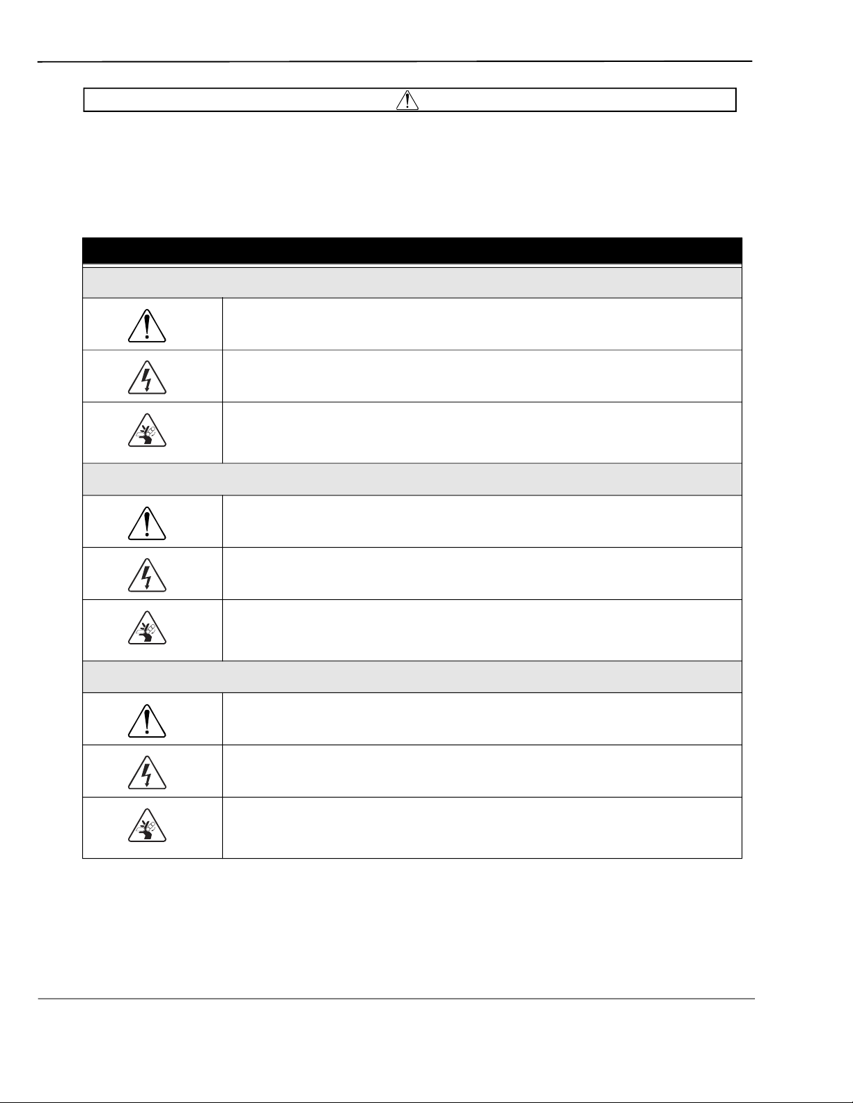
Table 1-2 Hazard Symbols
The exclamation point within the triangle is a warning sign alerting you of
important instructions in the instrument’s technical reference manual.
The lightning flash and arrowhead within the triangle is a warning sign alerting you
of “dangerous voltage” inside the product.
The pinch point symbol warns you that your fingers or hands will be seriously
injured if you place them between the moving parts of the mechanism near these
symbols.
Symboles de sécurité
Ce symbole signale l’existence d’instructions importantes relatives au produit
dans ce manuel.
Ce symbole signale la présence d’un danger d’électrocution.
Risque de pincement. Ces symboles vous avertit que les mains ou les doigts
seront blessés sérieusement si vous les mettez entre les éléments en mouvement
du mécanisme près de ces symboles
Warnungen und Vorsichtshinweise
Das Ausrufezeichen in Dreieck ist ein Warnzeichen, das Sie darauf aufmerksam
macht, daß wichtige Anleitungen zu diesem Handbuch gehören.
Der gepfeilte Blitz im Dreieck ist ein Warnzeichen, das Sei vor “gefährlichen
Spannungen” im Inneren des Produkts warnt.
Vorsicht Quetschgefahr! Dieses Symbol warnt vor einer unmittelbar drohenden
Verletzungsgefahr für Finger und Hände, wenn diese zwischen die beweglichen
Teile des gekennzeichneten Gerätes geraten.
1-8
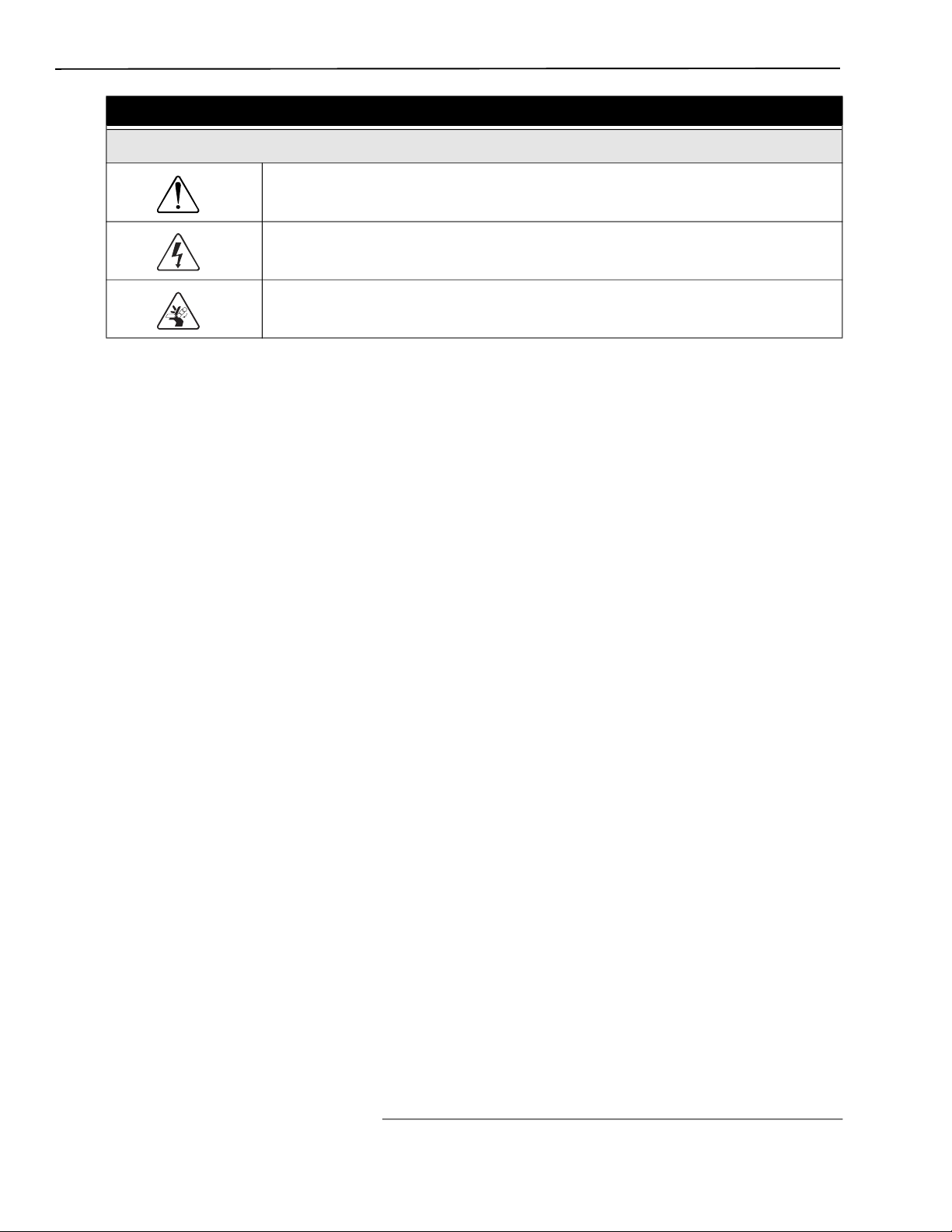
Table 1-2 Hazard Symbols (Continued)
Advertencias y Precauciones
Esta señal le advierte sobre la importancia de las instrucciones del manual que
acompañan a este producto.
Esta señal alerta sobre la presencia de alto voltaje en el interior del producto.
Punto del machacamiento. Sus dedos o manos seriusly serán dañados si usted
los coloca entre las piezas móviles cerca de estos símbolos.
1.7 For Additional Information
Technical assistance for the Torrent can be obtained from:
Teledyne ISCO
4700 Superior St.
Lincoln NE 68504
Phone: (800) 228-4373 or (402) 464-0231
Fax: (402) 465-3001
Email: IscoService@teledyne.com
Section 1 Introduction
1-9

CombiFlash Torrent® User Manual
1-10

Section 2 Preparation
This section provides instructions for unpacking and installing the CombiFlash Torrent
system. To prepare the system for operation, sequentially follow all instructions in sections
2.1 through 2.19. Some of these sections provide instructions for installing optional
equipment which should only be completed as required.
N ot Note
Section 2.21 contains an Installation Qualification checklist. If required, sign off the checklist
entries as you successfully complete the following sections.
2.1 Optional Equipment Modules
The Torrent/Torrent AQ offer several different optional modules. Each module will require
additional set-up steps as noted below. The optional modules are:
• Solvent Selection Valve (see Section 2.4.1; 2.6.2 and
CombiFlash Torrent
User Manual Guide
Section 2 Preparation
2.8).
®
• Sample Load Pump (see Section 2.6.1 and 2.12.1).
• Fractionation Valve (see Section 2.4.2; 2.6.3 and 2.12.3).
• Foxy R2 High Flow Fraction Collector (see Section 2.6.4; 2.12.2 and/or 2.17).
2.2 Unpacking the Unit
The Torrent is shipped in a single carton. The optional equipment will be shipped in
additional cartons. Carefully unpack the shipment and inspect the contents.
The Torrent is heavy. Use a two-person lift to prevent injury.
Lift the Torrent from the container using the lifting handles mounted on the side panels.
If there is damage to the shipping carton or any components, contact the shipping agent and
Teledyne ISCO (or its authorized representative) immediately.
If there is any evidence that the Torrent has been damaged in shipping, do not plug it into
AC power. Contact Teledyne ISCO or its authorized representative for advice.
Compare the contents of the boxes with the enclosed packing slips. If there are any shortages,
contact Teledyne ISCO immediately.
WARNING
WARNING
2-1
CombiFlash Torrent® User Manual Guide
2.3 Instrument Location
The Torrent has a relatively small footprint for a development-scale instrument, requiring
about 2200 square centimeters (350 in
least 3 cm (1.25") of air space behind it for ventilation. Additional space may be required for
solvent and waste containers, and fraction collection.
2
) of level bench space. Ensure that the Torrent has at
Refer to Table 1-1 for environmental condi
The system is heavy. Use a two-person lift to prevent injury.
Before making any connections to the Torrent, place it on the bench or in the fume hood where
it will be operated. Temporarily position the Torrent so you can access the back panel to
complete the connections.
2.4 Mounting Optional Modules
If a Solvent Select Valve or Fractionation valve are not being installed you can skip this section
nd continue to Section 2.5.
a
2.4.1 Solvent Select Valve (if purchased)
Place the Solvent Select Valve on the left-hand side of the Torrent with the valve facing the side
of the Torrent.
Use the supplied metal mounting plate and four (4) screws to secure the Solvent Select Valve to
the Torrent.
tions and power requirements.
WARNING
Figure 2-1 Solvent Select Valve mounted on Torrent
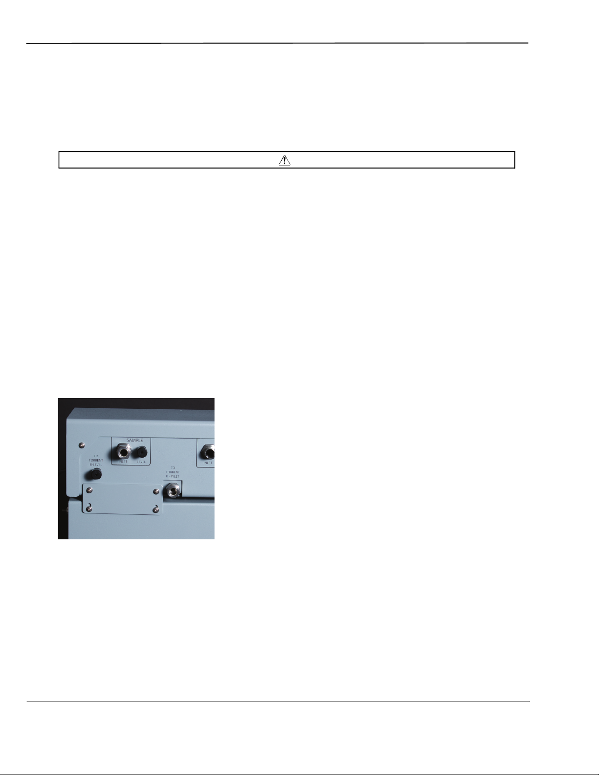
2.4.2 Fractionation Valve (if purchased)
Place the Fractionation Valve on the right-hand side of the Torrent with the Valve facing the
side of the Torrent.
2-2
Section 2 Preparation
Figure 2-2 Fractionation valve position before mounting.
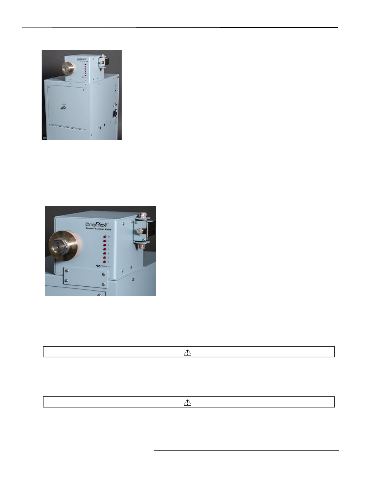
Use the supplied metal mounting plate and four (4) screws to secure the Fractionation Valve
to the Torrent.
Alternatively, the valve can be connected to a user supplied mast.
Figure 2-3 Fractionation valve after mounting
2.5 Connect Power
Ensure that the On/Standby switch above the touch screen panel is in the Standby position.
Then, use the
Mains power must meet the voltage, frequency, and amperage requirements listed on the
serial number label. Input voltage must be within ±10% of the region’s nominal line voltage.
In the USA, this is 117 volts ±11.7 volts.
As long as the AC mains power cord is connected to a live outlet, power is inside the unit.
The mains power cord is the disconnect device. Position the Torrent so that the power cord
supplied IEC power cord to connect the Torrent to mains power.
WARNING
WARNING
2-3
CombiFlash Torrent® User Manual Guide
can be unplugged, or use a power strip where the plug can quickly be removed from the outlet
in the event of an emergency.
Unless power must be removed due to an emergency, always wait at least one minute after
placing the system in Standby before removing the AC mains power cord.
2.6 Connect Interface Cables
Rear panel connections support a variety of devices. Electrical connections to networks or
optional equipment should be completed at this time.
CAUTION
Review the options below and complete as necessary. If any optional mo
installed you can continue to Section 2.7.
N ot Note
Detailed information about each of these optional devices is provided in Section 2.12 Plumbing
Optional Modules To Torrent.
2.6.1 Cabling: Sample Load Pump
To connect a Sample Load Pump to the Torrent, attach the pump’s power cable to the Torrent’s
back panel connector labeled “SAMPLE LOAD PUMP.”
dules are not being
Figure 2-4 Sample Load Pump power supply connection on back of Torrent.
2.6.2 Cabling: Solvent Select Valve
To connect a Solvent Select Valve to the Torrent, attach the valves power cable to the back
panel connector labeled “SAMPLE LOAD PUMP” and connect the USB cable to the USB port
on the back panel.
2-4
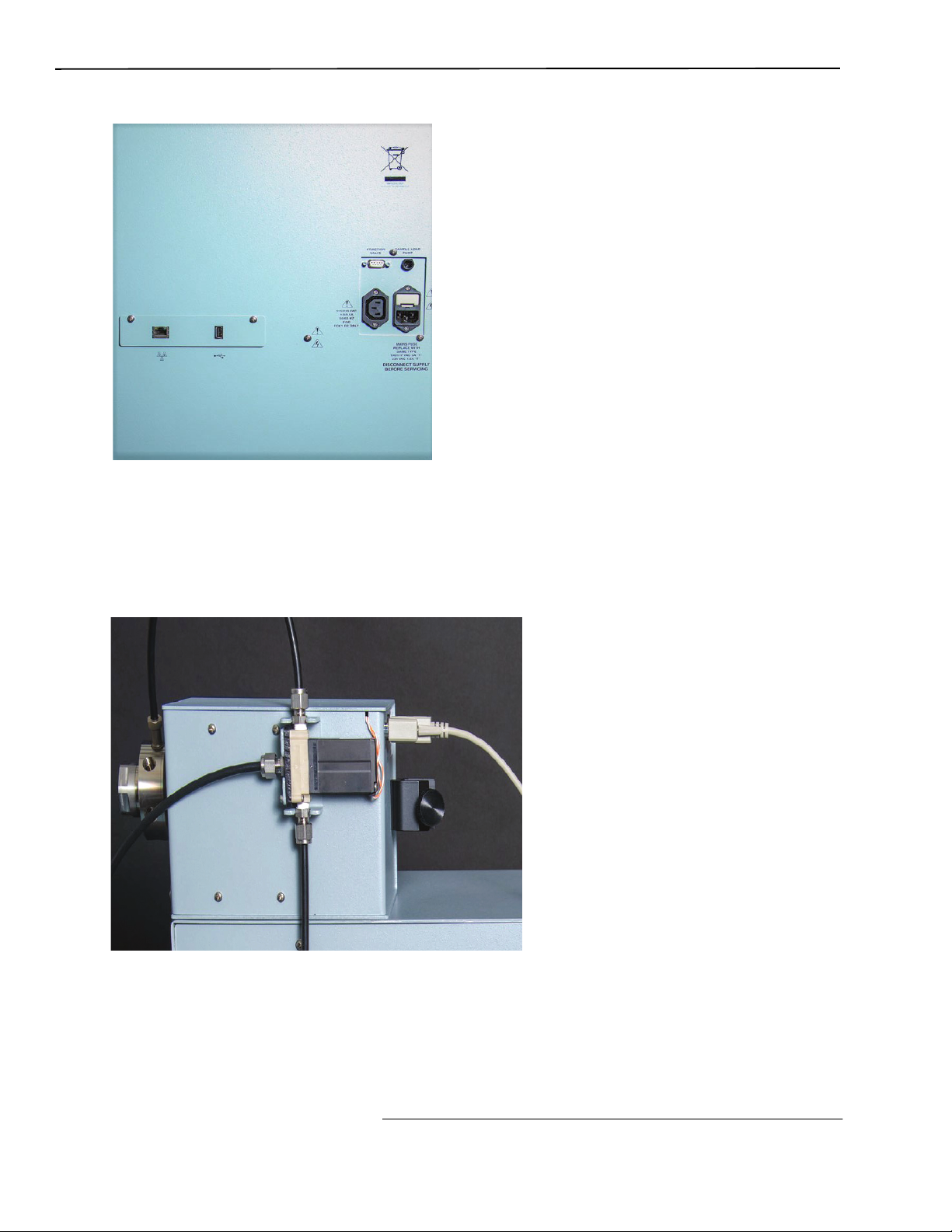
Figure 2-5 Back of Torrent for electrical connections
Section 2 Preparation
2.6.3 Cabling: Fractionation Valve
To connect a Fractionation Valve to the Torrent, attach the valve’s 9-pin power/control cable
between the port on the back of the Fractionation Valve to the Torrent’s back panel connector
labeled “FRACTION VALVE.”
Figure 2-6 Electrical Connection between Fractionation Valve and Torrent
2-5
CombiFlash Torrent® User Manual Guide
2.6.4 Cabling: Foxy R2 High Flow Fraction Collector
The Torrent can control up to four Foxy R2 High Flow fraction collectors via an Ethernet
network.
To connect one, or the first of multiple Foxys, connect a standard straight-through network
cable between the Ethernet ports on the Torrent and a Foxy. The second Ethernet port on the
Foxy can be used to add the next Foxy. See section 2.12.2 for more
The Torrent can supply AC power to one Foxy. Connect one end of the cable to the female IEC
connector on the Torrent. Connect the other end to the Foxy power connector.
details.
Figure 2-7 Connection on back of Foxy R2 Fraction Collector to the Torrent
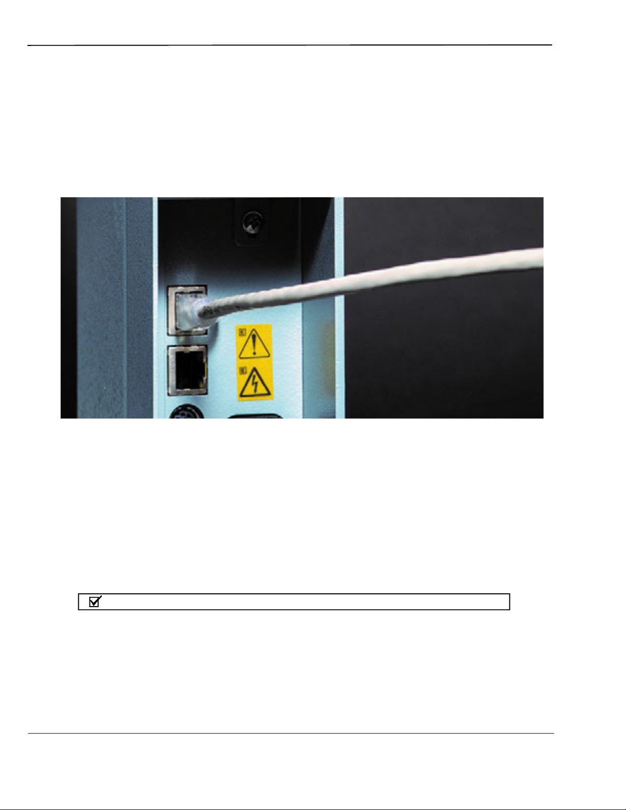
2.6.5 Cabling: Network Connection
The Torrent can be added to a network or directly connected to a computer for remote control.
To add the Torrent
the Torrent’s Ethernet port and your network.
To connect the Torrent directly to a computer, connect a “crossover” cable between the Ethernet
ports on the Torrent and a stand-alone computer.
To connect to a network, you will need access to IP addresses and network information from
your IT department. For more information on network guidelines, see TN28 Networking
Guidelines for CombiFlash Products, available at www.isco.com.
N ot Note
When using the Foxy R2 High Flow fraction collector, the Torrent’s rear panel Ethernet connector
will be in use. Instead, connect the cable to the available Ethernet port on the last Foxy in the chain.
to a network, connect a standard straight-through network cable between
2-6
N ot Note
The Foxy R2 fraction collector does not support DHCP. If you are adding the Torrent with Foxy R2
fraction collectors to your organization’s network, a static IP address must be assigned to each
unit. Contact your IT department for assistance.
N ot Note
Detailed information about networking the Torrent with one or more Foxys is provided in
Section 2.12.2.
2.7 Position the Torrent
After completing the various back panel connections, the Torrent can be moved to its
operating position. Turn the Torrent so that the operator can access all of the front view
features and controls. Use care not to damage the connections, cables and equipment while
moving
Ensure that the CombiFlash Torrent has at least 3 cm (1.25") of air space behind it for
ventilation.
the Torrent.
Section 2 Preparation
CAUTION
Determine where the solvent and waste containers will be located. Keep in mind that the
valve wash waste is located on the Torrent’s left side panel; diverter valve waste will come
from the fraction collector or fractionation valve, usually positioned on the right side of the
Torrent. If these will use a common waste container, determine the preferred location.
N ot Note
A common waste container is recommended for waste level monitoring to prevent overfilling.
2.8 Connect Solvent Select Valve Plumbing
If a Solvent Select Valve is not being installed you can skip this section and continue to
Section 2.9. If a Solvent Select Valve is to be installed with the Torrent or Torrent AQ it
should already be mounted.
2-7
CombiFlash Torrent® User Manual Guide
Figure 2-8 Solvent B Line connected to Solvent Selection Valve
1. Connect the preswaged end of black tubing (023050308) to Torrent “B INLET”.
2. Loosen (but don’t remove) the nut and 2-piece ferrule connected to the Solvent Select Valve
port “TO TORRENT B INLET”.
3. Place the free end of the black tubing into the port as far as it will go and finger tighten the
nut. Then use a wrench to tighten for a n additional 1 and 1/4 turn.
4. Locate a nut (60-0923-015) and ferrule (60-0083-163) in the accessory package
(60-5249-002).
5. Insert the ferrule, narrow end first, into the Torrent “B LEVEL”.
2-8
Figure 2-9 Solvent B Line on Torrent Connected to Solvent Selection Valve
6. Loosely thread the nut onto the “B LEVEL” port.

7. Insert the clear air supply line (supplied with Solvent Select Valve) into the “B LEVEL”
port until it is fully seated.
8. Finger tighten the nut. If desired, tighten the nut an additional 1/2 turn using a wrench.
9. Loosen the nut (but do not remove) to the Solvent Select Valve Port “TO TORRENT B
LEVEL”.
10.Following step 4 above, connect the air supply from the B LEVEL on the Torrent to the
Solvent Select Valve “TO TORRENT B LEVEL”.
2.9 Connect Solvent Lines
To prevent damage or premature wear to the pump and internal valves, clean solvent
should be used. The solvent should not contain any dissolved solids. In addition, the B
solvent pump on the Torrent and both Solvent A and Solvent B pumps on the Torrent AQ
are not compatible with alkanes such as hexane due to lack of lubricity. If using water as a
solvent, use Ultra Pure, DI or RO water.
Section 2 Preparation
CAUTION
CAUTION
If solvent containers are reused, particulate matter can accumulate in the container.
Containers should be thoroughly cleaned before each refill. Failure to clean the containers
may result in damage to the solvent selection valve and internal components.
N ot Note
The Torrent is shipped with protective caps on the solvent fittings. Remove these caps as you
connect the solvent lines. The internal solvent lines contain isopropyl alcohol, some of which may
drain when the caps are removed.
The Torrent may receive solvent from:
• User-supplied solvent containers at atmospheric pressure
• Pressurized or gravity-fed solvent delivery lines in the laboratory.
Refer to th
e appropriate installation section (2.9.1 through 2.9.2) according to your solvent
source.
2.9.1 Solvent Containers at Atmospheric Pressure
The Torrent can form a binary gradient from two solvents, A and B. These solvents connect to
the left side panel of the Torrent or Torrent AQ with optional Solvent Select Valve allows for a
binary gradient between one A solvent and either of two different B sol
1. Locate the Solvent A inlet line. This assembly consists of two tubes fastened together— a
solvent line and a smaller diameter air line to measure the solvent level.
vents or liquid sample.
2. Connect the large fitting to the Torrent’s A INLET port:
3. Position the end with the threaded fitting near the port.
2-9
CombiFlash Torrent® User Manual Guide
4. Rotate the fitting until the inlet line is routed the desired direction.
5. Finger-tighten the pre-swaged fitting to the port.
6. Use a wrench to tighten the fitting an additional
7. Connect the air line to the A LEVEL port (refer to Figure 2-10):
1
8 turn.
Nut
60-0923-015
Tubing
Figure 2-10 Level tubing connection with nut and ferrule
Ferrule
60-0083-163
Level Port
8. Locate a nut (60-0923-015) and ferrule (60-0083-163) in the accessory package
(60-5249-0
02).
9. Insert the ferrule, narrow end first, into the A LEVEL port.
10.Loosely thread the nut onto the A LEVEL port.
11.Insert the Solvent A air line into the A LEVEL port until it is fully seated.
12.Finger-tighten the nut. If desired, tighten the nut an additional
Important
1
2 turn using a wrench.
For systems without Solvent Select Valve follow steps 13-18. For systems with Solvent Select
Valve skip to steps 19-27.
13.Locate the Solvent B inlet line. This assembly consists of three tubes fastened together—a
solvent line, a smaller diameter air line, and a solvent line.
14.Connect the large fitting on the Solvent B inlet line to the Torrent’s B INLET port as
described in step 2.
2-10
15.Connect the smallest tube of the Solvent B inlet line to the B LEVEL port as described in
step 7.
16.Connect the remaining tube of the Solvent B inlet line to the B PRIME port:
17.Finger-tighten the pre-swaged fitting to the port labeled B PRIME.
18.Use a wrench to tighten the fitting an additional
Figure 2-11 Solvent A line connected to the Torrent
1
8 turn.
19.The Solvent Select Valve should be plumbed to the B Inlet of the Torrent.
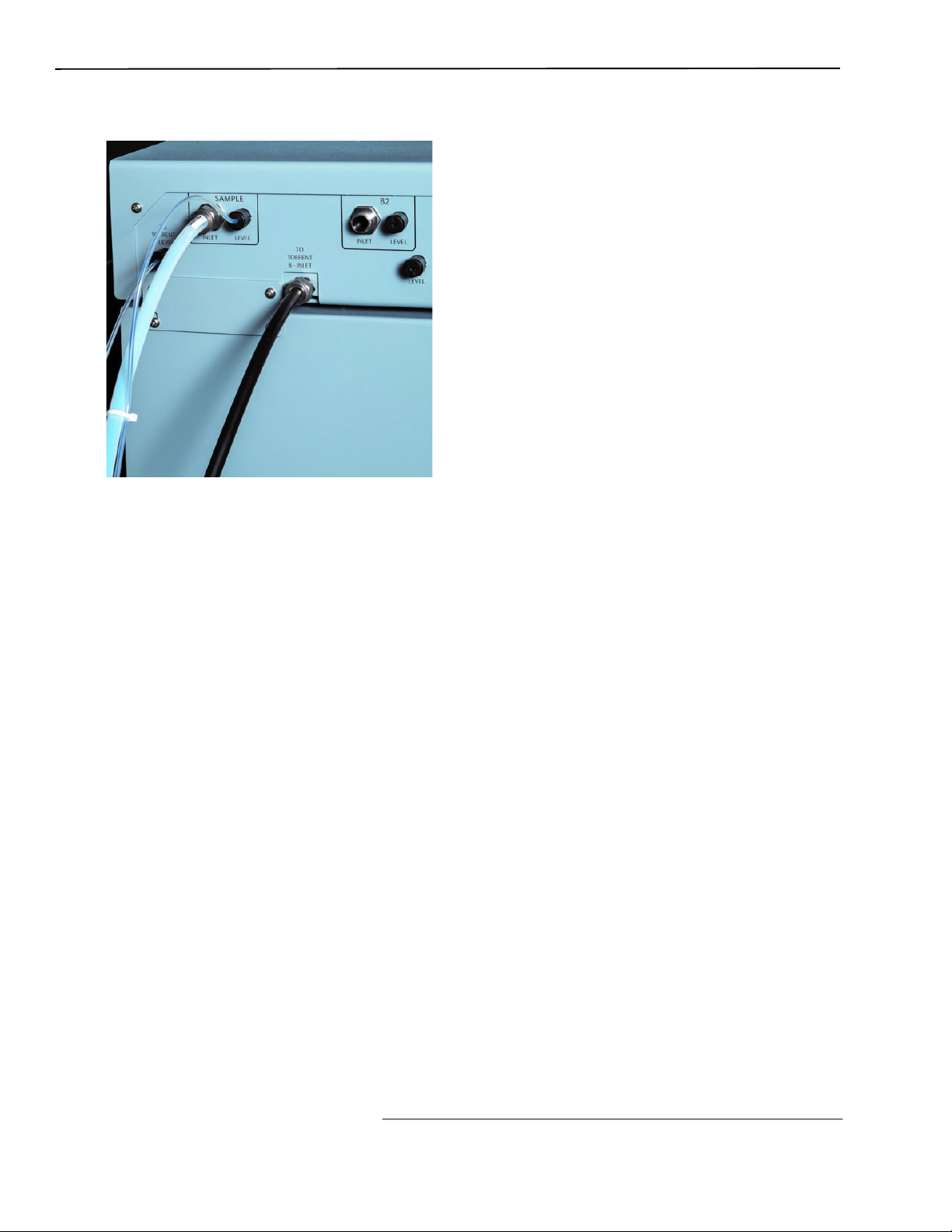
Figure 2-12 Sample Inlet Line connected to Solvent Selection Valve
Section 2 Preparation
20.Locate the Sample Inlet line. This assembly consists of two tubes fastened together--a
white solvent line and a smaller diameter air line.
21.Connect the large tubing on the sample line to the Solvent Select Valve’s SAMPLE INLET
port with the pre-swaged nut and ferrule The connection should be finger-tight. Then, use
a wrench to tighten the fitting an additional 1/8 turn.
22.Connect the smaller tube of the sample inlet line to the Solvent Select Valve’s SAMPLE
Level port as
described in step 7.
23.Locate the Solvent B1 inlet line. This assembly consists of two tubes fastened together--a
solvent line and a smaller diameter air line.
24.Connect the large fitting on the Solvent B1 inlet line to the Solvent Select Valve’s B1
INLET port as described in step 2 above.
25.Connect the smalled tube of the Solvent B1 inlet line to the Solvent Select Valve’s B1 inlet
line to the Solvent Select Valve’s B Level port as described in step 7.
26.Locate the Solvent B2 inlet line and repeat Steps 24 and 25 for the B2 inlet line.
2-11
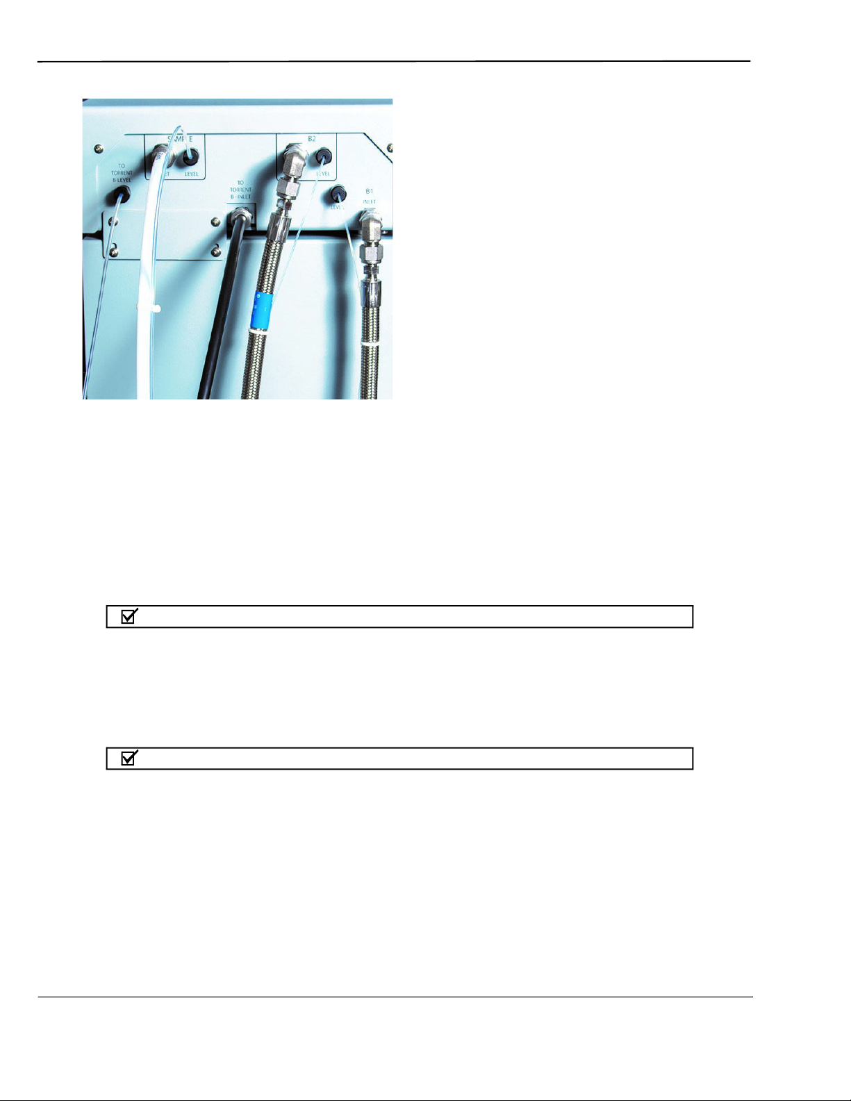
CombiFlash Torrent® User Manual Guide
Figure 2-13 Solvent B1 and B2 supply lines connected to Solvent Selection Valve
The other ends of the Solvent A and B lines should be placed in the respective solvent
containers.
27.If installing onto a Torrent (not AQ), locate the 1/8-inch plug, part number 209-0165-21, in
accessory kit 60-5249-002. Install this plug on the B Prime port.
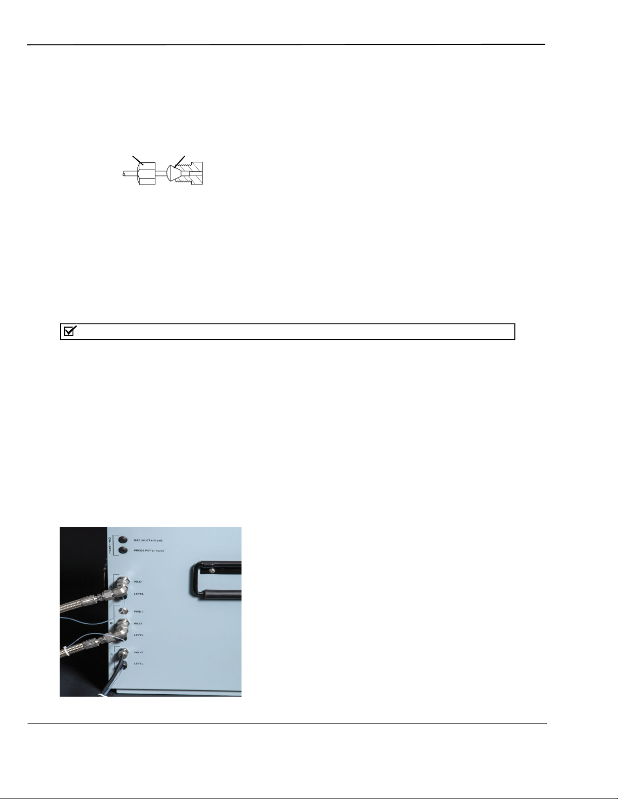
2.9.2 Pressurized Solvent Lines in the Laboratory
When receiving solvent from pressurized lines on-site, the Torrent’s solvent level sensing
feature is unsupported (and unnecessary).
N ot Note
The solvent pressure should be regulated to not exceed 5 psi.
To complete the solvent connections:
1. Ensure that the solvent supply lines have shut-off valves. These valves must be accessible to
the user.
N ot Note
The solvent supply should be shut-off when the system is not in use. Otherwise, pressurized
solvent may be forced through the CombiFlash Torrent pump seals and leak from the waste port or
other fluid path from the automated injection valve.
2. Locate the
plug on the B Prime port.
3. Connect user-supplied tubing with
ports on the side panel.
1
8-inch plug, part number 209-0165-21, in accessory kit 60-5249-002. Install this
3
8-inch fittings from the source to the A Inlet and B Inlet
2-12
N ot Note
Solvent Level Sensing and B Solvent Prime options should be disabled when completing the
system configuration settings.
2.10 Connect Waste Lines
Risk of fire or equipment damage. Failure to connect Waste Port tubing may allow organic
solvents to pool in unsafe areas, possibly creating dangerous levels of flammable vapors.
Elevated flammable vapor levels are possible. Ensure that the waste container is
adequately ventilated, preferably by placing it in a fume hood.
N ot Note
The Torrent is shipped with protective caps on the waste fittings. Remove these caps as you
connect the waste lines. The internal solvent lines contain isopropyl alcohol, some of which may
drain when the caps are removed.
Section 2 Preparation
WARNING
CAUTION
N ot Note
Waste connections on the left side panel are labeled with a Waste icon.
The waste tube assembly is a bundle of two tubes that routes post-run valve wash fluid to a
waste container. Instructions for diverter valve waste tubing is covered in section 2.12.
Figure 2-14 Waste Line connected to the Torrent
2-13

CombiFlash Torrent® User Manual Guide
To connect the waste tube assembly to the Torrent:
1. Select the tube with the pre-swaged nut and ferrule and connect this end to the port labeled
VALVE. The connection should be finger-tight. Then, use a wrench to tighten the fitting an
1
additional
8 turn.
2. Connect the other line to the LEVEL port.
3. Locate a nut (60-0923-015) and ferrule (60-0083-163) in the accessory package
(60-5249-002).
4. Inser
t the ferrule, narrow end first, into the LEVEL port.
5. Loosely thread the nut onto the LEVEL port.
6. Insert the waste air line into the LEVEL port until it is fully seated.
7. Finger-tighten the nut. If desired, tighten the nut an additional
1
2 turn using a wrench.
The other ends of the Waste line should be placed in the waste container.
If using the optional Waste Outlet Cap (60-5394-512 for 83B clo
sures, 60-5394-513 for 100 mm
closures), proceed with the following steps:
8. Place the metal plate inside the plastic cap (Figure 2-15). The plate should be oriented so
that the small tube will extend into the carboy. The small tube should extend 5 ±0.5 cm long
from nut. If the tube is missing, insert it now and finger-tighten the nut.
Nut
Metal Plate
Spring-type
Retainer
Place a retainer above and
5 cm tube extending
into carboy
Figure 2-15 Optional Waste Cap (83B cap shown)
below the metal plate.
2-14
9. The tubing is secured using metal, spring-type retainers. A pair of conventional pliers will
allow you to op
en the retainer enough to slide it onto the tubing. On the larger diameter
waste tube, slide one retainer about 2 inches (5 cm) onto the tubing end.
10.Feed this tube into the top of the metal plate until the retainer is against the top of the
plate.
11.Slide a retainer onto the tubing end until it is seated against the bottom of the metal plate.
12.Thread the cap onto the carboy.
13.The smaller diame
ter tube is the level sense tube. Push this tube about 2 cm into the top
fitting and finger-tighten the nut.
If an optional waste cap is not used, ensure the waste lines are secured so they drain into the
waste container. Secure the Waste Level Sense air tubing so its outlet is at least two inches (5
cm) below the container’s maximum level. Seal the container opening to avoid solvent vapors.
2.11 Connect and Route Drain Line
WARNING
Risk of fire or equipment damage. Failure to connect drain lines may allow organic solvents
to pool in unsafe areas, creating a potential for dangerous levels of flammable vapors.
Improper draining may damage the instrument’s internal components.
The Torrent has a front-mounted drip tray. There is a drain connection under the left side of
the tray. Connect user-supplied tubing to this drain and route it to a suitable waste fluid
collection container.
2.12 Plumbing Optional Modules to Torrent
The installation of optional equipment that was electrically connected to the Torrent in
section 2.6 should be completed now. Review the options below and complete as necessary. If
any optional modules are not being installed you can skip this section and continue to section
2.13.
2.12.1 Optional Sample Load Pump
1. Position the Sample Load Pump on top or near the Torrent.
Section 2 Preparation
2. Connect the tubing between the pump outlet (from the bottom of the pump head) and the
Torrent’s sample injection port (Figure 1-1, item 9).
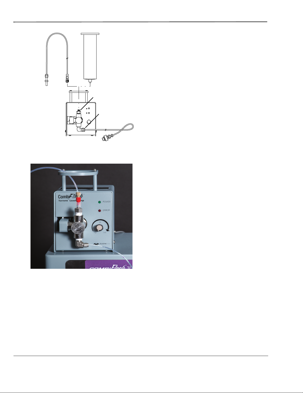
3. Configure the Sample Load Pump by placing either the plastic cartridge reservoir or the
tubing with the weighted end on the pump inlet (Figure 2-17).
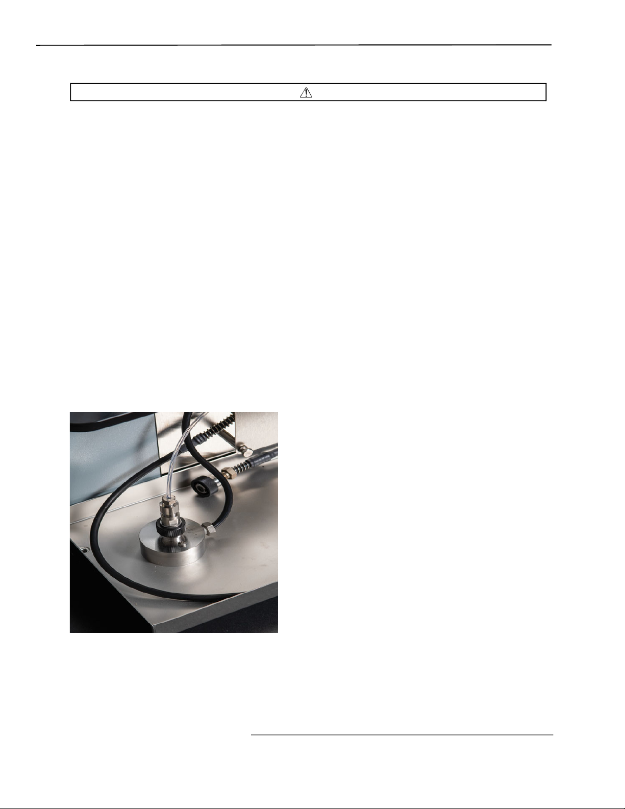
Figure 2-16 Sample Load Pump connected to the Torrent Sample Injection Port.
2-15
CombiFlash Torrent® User Manual Guide
Tubing with
Weighted End
Figure 2-17 Sample load pump
Cartridge Reservoir
Pump Inlet
Pump Outlet
To Sample Injection Port
Figure 2-18 Plumbing Sample Inlet to Sample Loading Pump
2.12.2 Optional Foxy R2 High Flow Fraction Collector
The fraction collector(s) should be positioned to the right of the Torrent. Complete information
about the Foxy R2 fraction collector is provided in its user manual, part #69-2133-667.
Plumbing Setup:
1. Connect the 107 cm (42 inch) piece of supplied tubing between the Torrent’s TO
COLLECTOR port and the fraction collector’s diverter valve IN port (Common). Use caution
when tightening the hardware to prevent damage to the dive
2-16
rter valve.
 Loading...