

Page 1
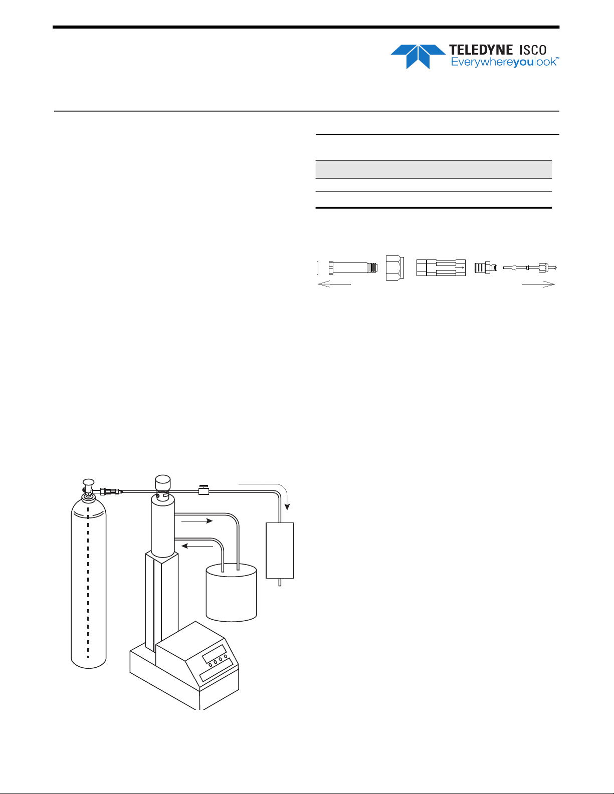
CO2 Applications &
CO2
Connection
Kit
CO
2
Circulating
Bath
User-supplied
Device
(Extruder
Reactor
Rock
Core etc.)
Syringe Pump
T.C. Jacket
Dip Tube
Technical Notes
For Teledyne ISCO Syringe Pumps
Overview
Supercritical CO2 and its associated technologies are
being used in many applications to replace hazardous
solvents, lower costs, and improve efficiencies. Some of
the applications requiring a supercritical fluid pump
include:
• Carbon Sequestration Studies
• Supercritical Fluid Extraction (SFE)
• Supercritical Fluid Chromatography
• (SFC) Catalysis/Reaction Feed
• Injection molding and Extrusion
• Particle Formation
• Cleaning
• Electronic Chip Manufacturing
• Plastics Production
Teledyne ISCO Syringe Pumps are used in R&D and
production in many of these applications. Syringe
pumps are well-suited for use with CO
at high pressures with great accuracy and reliability.
and can operate
2
Syringe Pump Technical Bulletin
TB08
Table 1: CO2 Cylinder Connection Assembly
Part Number Description
CGA-330 Fitting - short (Brass)
CGA-320
PTFE
washer
To CO
Supply
Nipple
2
Figure 2: CO
cylinder connection assembly
2
Nut
Washer - Teflon
Inline filter
frit assembly
Reducing
connector
To Valve
Inlet
Tips and Additional Equipment:
CO2 Cylinder Connection
For North American gas tank connections, customers
are instructed to purchase connecting parts from other
suppliers, such as: Matheson. CO
parts can be found at: http://store.mathesongas.com
cylinder connection
2
1. Dip Tube
An upright CO2 cylinder must be equipped with a dip
tube in order to pump a steady supply of liquid and not
gas. The dip tube is a piece of copper tubing plumbed
from the valve at the top of the tank to the bottom.
2. Temperature Control
To ensure a good fill, maintain the temperature in the
cylinder with the Isco temperature control jacket. The
temperature control jacket is useful in SFC applications
where cylinder cooling facilitates pump filling with
supercritical liquid CO
lating temperature-controlled bath (user supplied) to
keep the fluid inside the pump at a constant temperature. This can be critical when operating at very low
flow rates (below 100 µl/min), where temperature fluctuation can cause flow variations.
Pump systems are available from Teledyne ISCO with
the temperature control jacket already installed. For
existing systems, order the appropriate package for
your pump model. Refer to Technical Bullet
perature Control Jacket for additional information about
installation and operation.
3. Valve Packages for Dual Pump Systems
A continuous flow system consists of two syringe
pumps and a valve package regulated by one controller.
This allows you to continuously deliver liquefied gas in
Figure 1: ISCO Pump and CO2 dip tube tank
with
constant flow or constant pressure mode.
ISCO temperature control jacket and circulating bath
. The jacket is used with a circu-
2
in TB07 Tem-
Page 2
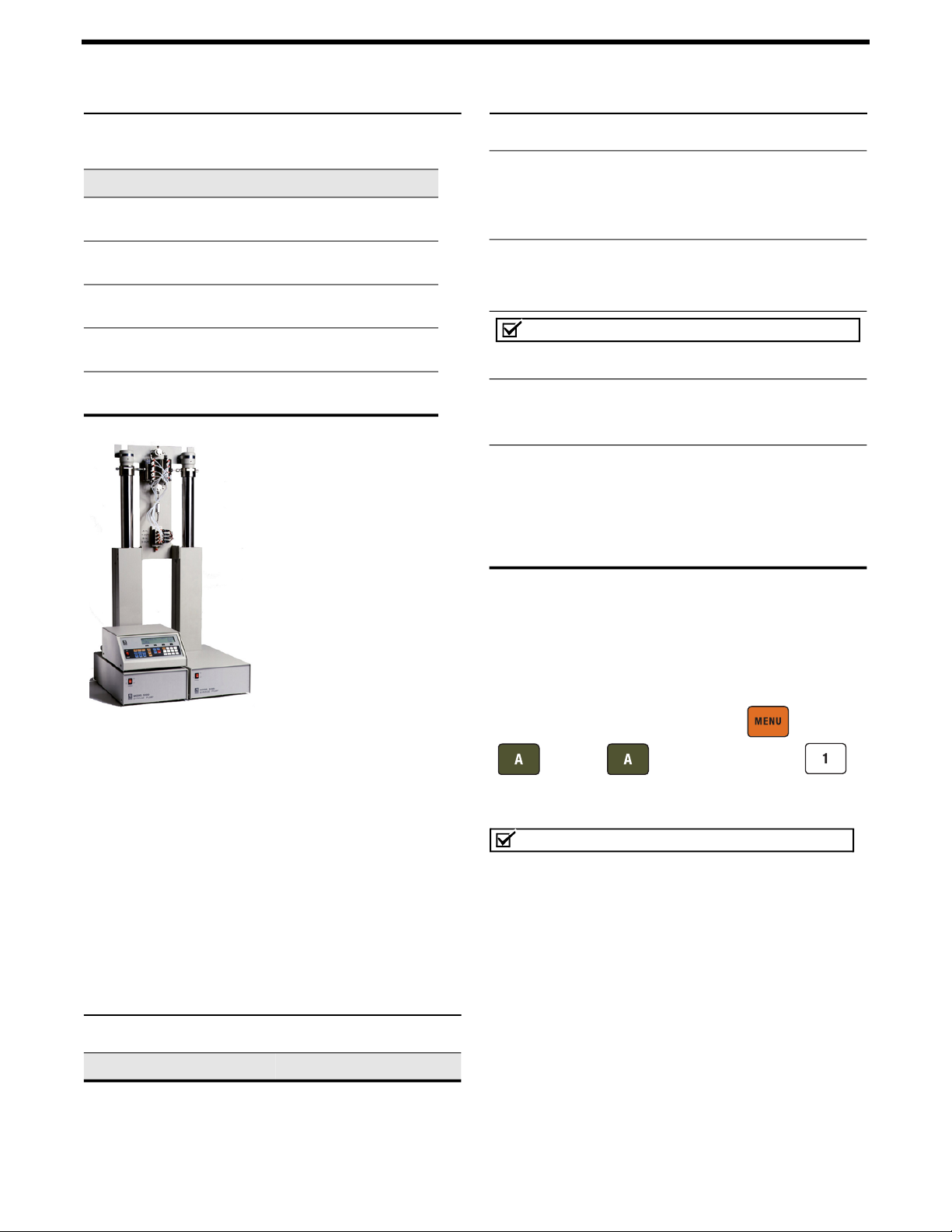
Syringe Pump Technical Bulletin TB08
Table 2: Pump Systems with Pre-Installed
Temperature Control Jacket
Item Description Part Number
100DM pump w/ controller & T. C. Jacket
100DM pump only w/ T.C. Jacket
100DX pump w/ controller & T. C. Jacket
100DX pump only w/ T.C. Jacket
260D pump w/ controller & T. C. Jacket
260D pump only w/ T.C. Jacket
500D pump w/ controller & T. C. Jacket
500Dpump only w/ T.C. Jacket
1000D pump w/ controller & T.
C. Jacket
1000D pump only w/ T.C. Jacket
Teledyne ISCO has three
different types of valve
packages:
- Electric valves
- Air valves
- Manual valves
Electric valves, which provide the best positive valve
closure, are the most commonly used valves in
liquefied gas applications.
Electric valves require the
pump controller to be
equipped with the valve
driver board.
Air valves generally open
and close faster and are less prone to error and compo
nent wear, making them suitable for industrial use and
other applications where the system will be constantly
running; however they require a user-supplied pressurized air source and special upgrade kit in order to
operate with CO
compatible.
Manual valves are used in lower-cost CO
tions where automation is not required.
For detailed installation and operation instructions,
refer to Technical Bulletin #1 Dual Pump Systems.
. All other wetted materials are CO2
2
67-1240-321
68-1240-029
67-1240-320
68-1240-043
67-1240-301
68-1240-028
67-1240-311
68-1240-030
67-1240-601
68-1240-601
applica-
2
Table 3: Valve Packages for Dual Systems
Valve Package Part #
Table 3: Valve Packages for Dual Systems
Electric
1000D
500D
260D/100DM/DX
Controller for electric valves
Air
1000D
500D
260D/100DM/DX
68-1247-109
68-1247-091
68-1247-090
68-1240-062
60-1247-104
60-1247-061
60-1247-058
Note
Air valves require a special upgrade kit in order to
operate with CO
Air Valve Upgrade Kits:
Manual
1
8
/
”
1
4”
/
1000D Refill
1000D Outlet
500D Refill
500D Outlet
260D/100DM/DX Refill
260D/100DM/DX Outlet
.
2
60-5364-234
60-5364-259
68-1247-117
68-1247-118
68-1247-083
68-1247-082
68-1247-077
68-1247-078
1
8
/
”
1
8”
/
4. Low Tank Level Alarm
In constant pressure mode, the Poor Fill feature
allows you to set a fill point as a percentage of pump
volume. If this volume percentage is not reached after a
refill and re-pressurization, the system sounds an alarm
and stops the pump.
MENU ( ) > MORE
-
To activate the alarm, press
( ) >
MORE ( ), and select POOR FILL ( ).
CO2 with Modifier
Note
See the Modifier Addition section of your user manual
for detailed information about two-pump (CO
modifier) systems.
A dual pump system in constant pressure mode
pumping supercritical CO
delivering a modifier (usually a solvent) can dispense a
mixture with a programmable v/v ratio, with the Modifier Addition Kit (part #68-1247-079) installed. Both
fluids pass through
meet and are blended in a mixing tee (see Figure 3 on
the following page).
Note that the CO
package mounting bracket before emerging at the valve
inlet.
one-way check valves
2
combined with a third pump
2
before they
input tubing runs behind the valve
2
&
Page 3

Syringe Pump Technical Bulletin TB08
Solvent
modifier
Mixing tee
CO
2
Valve pkg
Figure 3: Modifier addition setup
valve package
Before operation in modifier mode, zero and fill the
pumps under indep
mode (see Initial Preparation for Modifier Addition in
Section 9 of your D Series user manual).
endent control/constant pressure
Modifier Mode
Once the pumps are ready, place them in modifier
mode:
MENU ( ) > MORE ( ) > MULTI-PUMP
Press
( ), and select
( ) three times to return to the main menu. The
screen will display the words
Teledyne Isco
P.O. Box 82531, Lincoln, Nebraska, 68501 USA
Toll-free: (800) 775-2965 • Phone: (402) 464-0231 • Fax: (402) 465-3001
E-mail: IscoService@teledyne.com
Teledyne Isco is continually improving its products and reserves the right to change product
specifications, replacement parts, schematics, and instructions without notice.
MODIFIER ( ). Press PREVIOUS
MODIFIER ON.
Shown with electric
Modifier Concentration
To set the modifier concentration, press % PUMP
( ). Use the numeric keys to enter the desired per-
centage of modifier and press
Note
For additional important information about setup and
operation of the modifier addition system, consult
Section 9 of your D Series user manual.
ENTER to save the value.
Last modified April 12, 2021
 Loading...