

Teledyne Continental Motors Sandcast Series, IO-550-D, IO-550-E, IO-550-F, IO-550-L Maintenance And Operator's Manual
Page 1

MODEL IO-550-D, E, F & L
SANDCAST SERIES
©
CONTINENTAL
AIRCRAFT ENGINE
MAINTENANCE AND
OPERATOR’S
MANUAL
TM
Teledyne Continental Motors, Inc.
FORM X30605 FAA APPROVED
©1990 TELEDYNE INDUSTRIES, INC. APRIL 1990
Page 2

MAINTENANCE
MANUAL
-
Teledyne Continental Motors (TCM) engine operating instructions are generated prior to and independently of
the aircraft operating instructions established by the
airframe manufacturer.
developed using factory controlled parameters that are
not necessarily the same as those specifications required to satisfy a specific aircraft
Because of this difference the aircraft operator should
use the airframe manufacturer's operating instructions
in
found
operating the aircraft unless otherwise specified by the
original airframe manufacturer.
the Pilots Operating Handbook
AND
NOTICE
TCM's operating instructions are
OPERATOR'S
-
/
engine installation.
(POH)
while
FORM
NO.
X30605
Page 3
MAINTENANCE
AND
FOR
OPERATOR'S MANUAL
10-550t),E,F,L
The operator must comply with all the instructions contained in this manual in order to assure
safe and reliable engine performance. Failure to comply will be deemed misuse, thereby relieving the engine manufacturer
This manual contains
dures contained herein provide the operator with technical information and instructions applicable to safe operation.
no
of
warranties, either expressed or implied. The information and proce-
AIRCRAFT ENGINE
responsibility under its warranty.
Page 4
CHAPTER
Chapter Page
INDEX
1 Introduction 1-1
2 Tools and Equipment 2-1
3
4
5
6
7
8
9
10 Troubleshooting 10-1
1 1 Engine Preservation and Storage 11-1
12 Airworthiness Limitations 12-1
13 Engine Performance and Cruise Control 13-1
Detailed Engine Description 3-1
Engine Specifications and Operating Limits 4-1
Unpacking. Installation. Testing & Removal 5-1
Normal Operating Procedures 6-1
Emergency Operating Procedures 7-1
Abnormal Environmental Conditions 8-1
Service and Maintenance 9-1
...............................................
..........................................
......................................
..............................
..............................
.....................................
...................................
..................................
.......................................
...........................................
..................................
.......................................
...............................
Page 5
CHAPTER
1
INTRODUCTION
Section
Section
1-1
1-2 Related Publications 1-3
1-3 Abbreviations and Glossary
1-4 Manual Revisions 1-9
scope
............................
....................
......................
Index
Page
of
Terms 1-4
...........
..
1.2
Page 6
INTRODUCTION
1-1
SCOPE
Recommendations, cautions and warnings regarding operation of this engine are not intended to impose
undue restrictions, but are inserted to enable the pilot to obtain maximum performance from the engine
commensurate with safety and efficiency. Abuse, misuse, or neglect
cause eventual failure. In the case of an
trous
consequences. Failure to observe the instructions contained in this manual constitutes unautho-
rized
operation in areas unexplored during development of the engine, or in areas which experience has
proved to be undesirable or detrimental.
Notes, Cautions and Warnings are induded throughout this manual. Application is as
NOTE. . .Special interest information which may facilitate the operation of equipment.
.
CAUTION.
gine or accessories.
WARNING.
the engine
.Information issued to emphasize certain instructions or to prevent possible damage to en-
.
.Information which, if disregarded, may result in severe damage to or destructi~n of
or
endangerment to personnel.
aircmft engine
it
should
of
any piece of equipment can
be
obvious that a failure may have disas-
follows:
Page 7
1-2
RELATED
PUBLICATIONS
1. Overhaul Manual for 10-550D,E,F,L Series Aircraft
Engine. Form
2.
Illustrated Parts Catalog for 10-550 Series Aircraft
Engine. Form
X30607A.
X30606A.
3. Teledyne Continental Motors Aircraft Engine Service Bulletins.
4.
Fuel Injection Manual. Form X30593A.
The above publications can be ordered through your
Teledyne Continental Motors Distributor or ordered
if
directly,
prepaid, from:
Teledyne Continental Motors
Aircraft Products Division
P.
0.
Box 90
Mobile, AL 36601
Attn: Accounts Receivable
II. Accessory Manuals:
A. Ignition System
Master Service Manual
TCM lgnition Systems and Components
Form
X40000
Teledyne Continental Motors
Aircraft Products Division
P.
0.
Box 90
Mobile, Alabama 36601
Attn: Publications Dept.
B. Starter Motor
Service Manual
Teledyne Continental Motors
Aircraft Products Division
0.
Box 90
P.
Mobile, Alabama 36601
Attn: Publications Dept.
C. Alternator
Alternator Service Instructions
Form X30531-3
Teledyne Continental Motors
Aircraft Products Division
P.
0.
Box 90
Mobile, Alabama 36601
Attn: Publications Dept.
Page 8
1-3
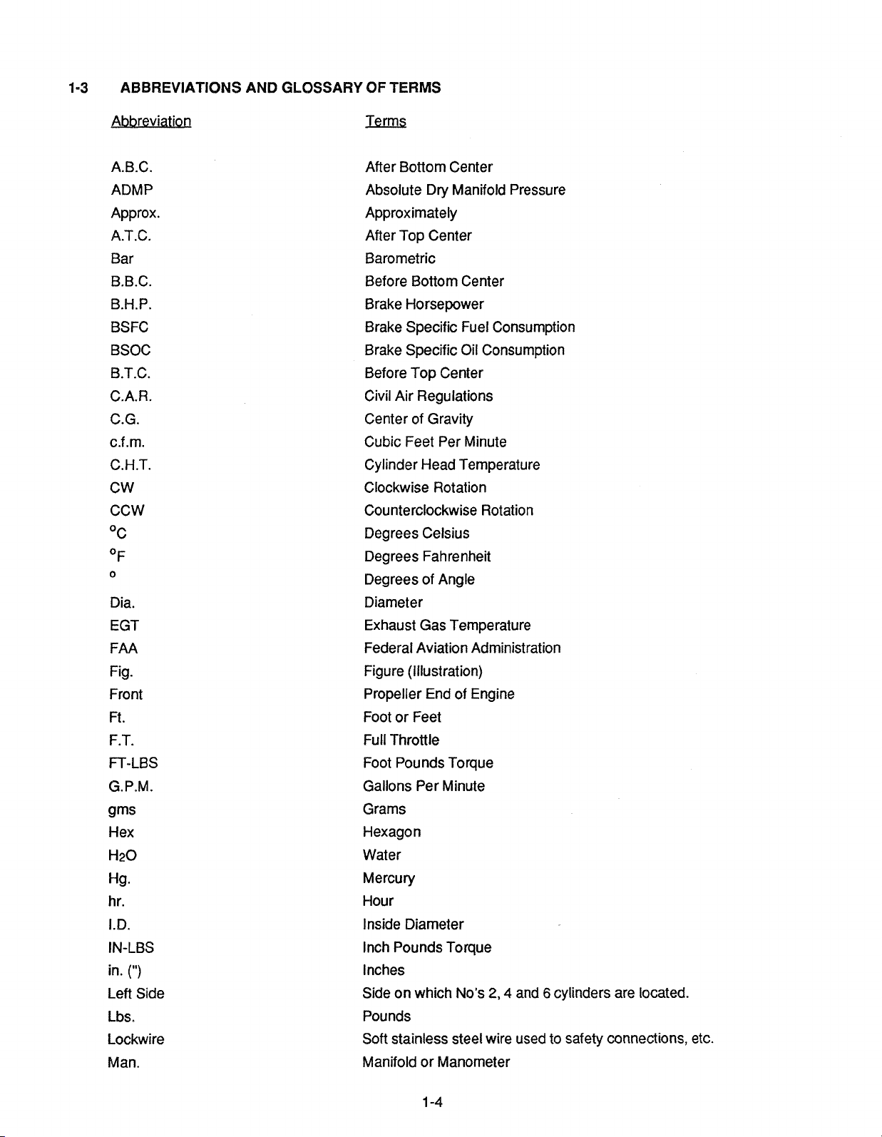
ABBREVIATIONS AND GLOSSARY OF TERMS
Abbreviation
A.B.C.
ADMP
Approx.
A.T.C.
Bar
B.B.C.
B.H.P.
BSFC
BSOC
B.T.C.
C.A.R.
C.G.
c.f.m.
C.H.T.
CW
CCW
Dia.
EGT
FAA
Fig.
Front
Ft.
F.T.
FT-LBS
G.P.M.
gms
Hex
H20
Hg.
hr.
I.D.
IN-LBS
(")
in.
Left Side
Lbs.
Lockwire
Man.
After Bottom Center
Absolute Dry Manifold Pressure
Approximately
After Top Center
Barometric
Before Bottom Center
Brake Horsepower
Brake Specific Fuel Consumption
Brake Specific Oil Consumption
Before Top Center
Civil Air Regulations
Center of Gravity
Cubic Feet Per Minute
Cylinder Head Temperature
Clockwise Rotation
Counterclockwise Rotation
Degrees Celsius
Degrees Fahrenheit
Degrees of Angle
Diameter
Exhaust Gas Temperature
Federal Aviation Administration
Figure (Illustration)
Propeller End of Engine
Foot or Feet
Full Throttle
Foot Pounds Torque
Gallons Per Minute
Grams
Hexagon
Water
Mercury
Hour
Inside Diameter
Inch Pounds Torque
Inches
Side on which No's
2,4
and 6 cylinders are located.
Pounds
Soft stainless steel wire used to safety connections, etc.
Manifold or Manometer
Page 9
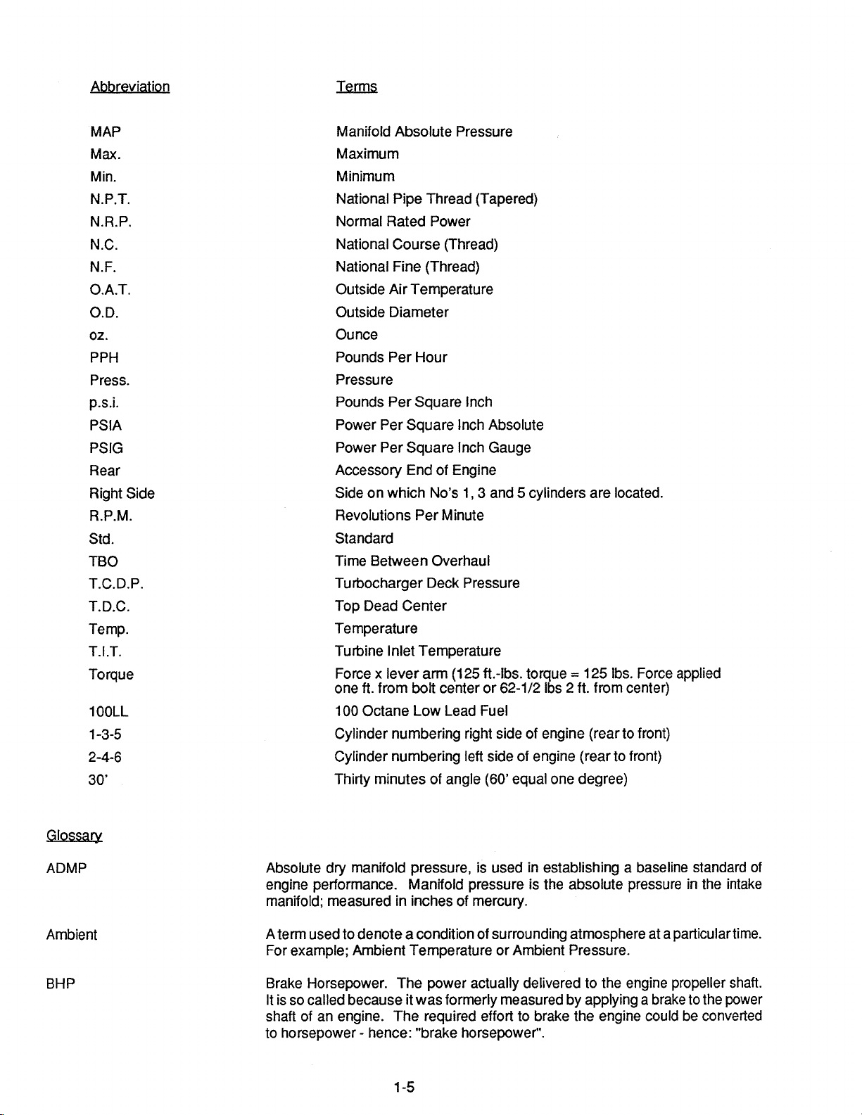
Abbreviation
MAP
Max.
Min.
N.P.T.
N.R.P.
N.C.
N.F.
O.A.T.
O.D.
02.
PPH
Press.
p.s.i.
PSlA
PSlG
Rear
Right Side
R.P.M.
Std.
TBO
T.C.D.P.
T.D.C.
Temp.
T.I.T.
Torque
1
OOLL
1-3-5
2-4-6
30'
Manifold Absolute Pressure
Maximum
Minimum
National Pipe Thread (Tapered)
Normal Rated Power
National Course (Thread)
National Fine (Thread)
Outside Air Temperature
Outside Diameter
Ounce
Pounds Per Hour
Pressure
Pounds Per Square lnch
Power Per Square lnch Absolute
Power Per Square lnch Gauge
Accessory End of Engine
Side on which No's 1, 3 and 5 cylinders are located.
Revolutions Per Minute
Standard
Time Between Overhaul
Turbocharger Deck Pressure
Top Dead Center
Temperature
Turbine Inlet Temperature
Force
x
lever arm (1 25 ft.-lbs. torque = 125 lbs. Force applied
one ft. from bolt center or 62-1/2
100 Octane Low Lead Fuel
Cylinder numbering right side of engine (rear to front)
Cylinder numbering left side of engine (rear to front)
Thirty minutes of angle (60' equal one degree)
lbs 2 ft. from center)
Glossarv
ADMP
Ambient
BHP
Absolute dry manifold pressure, is used in establishing a baseline standard of
engine performance. Manifold pressure is the absolute pressure in the intake
manifold; measured in inches of mercury.
A term used to denote a condition of surrounding atmosphere at a particulartime.
For example; Ambient Temperature or Ambient Pressure.
Brake Horsepower. The power actually delivered to the engine propeller shaft.
It is so called because it was formerly measured by applying a brake to the power
shaft of an engine. The required effort to brake the engine could be converted
to horsepower
-
hence: "brake horsepower".
Page 10
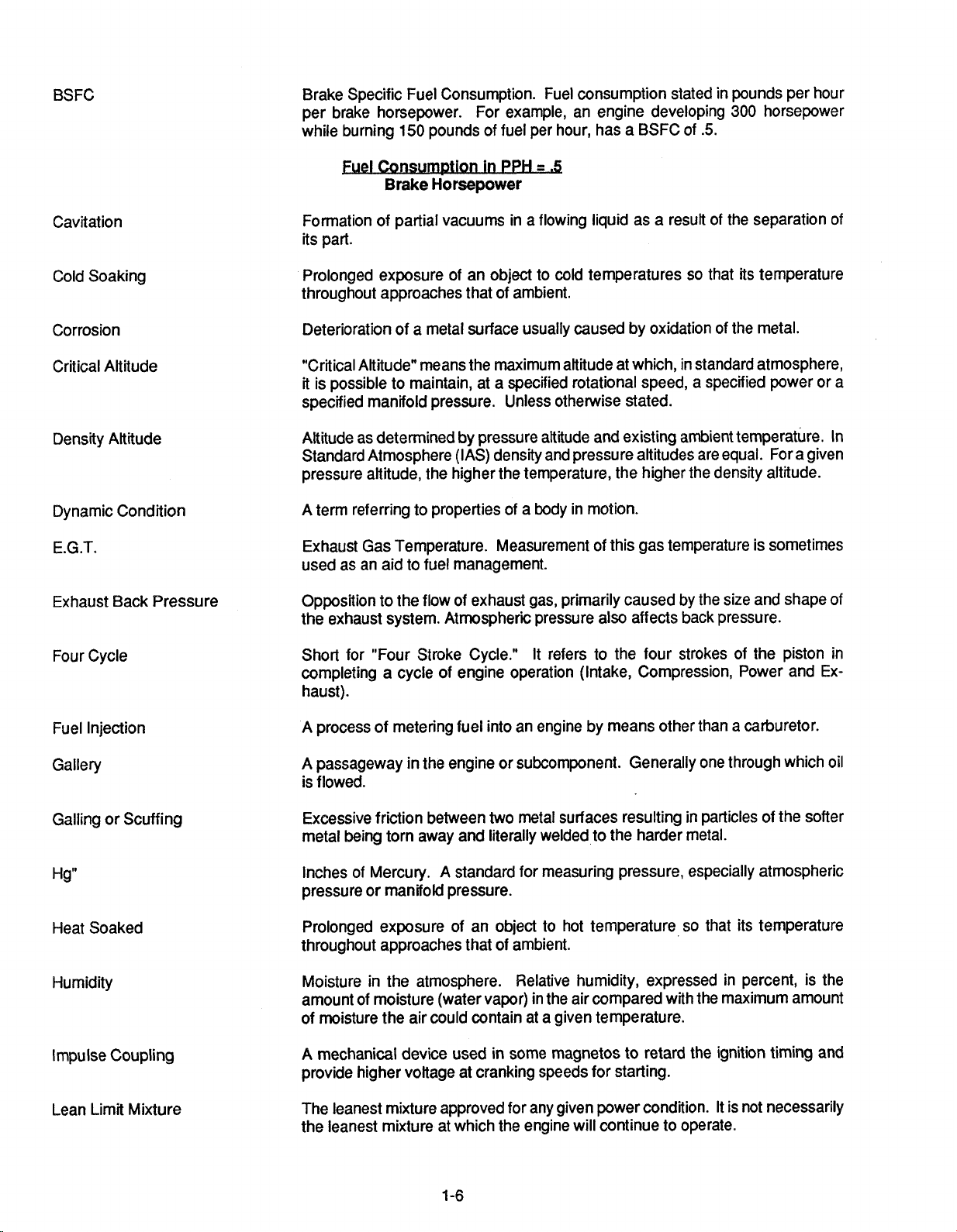
BSFC
Brake Specific Fuel Consumption. Fuel consumption stated in pounds per hour
per brake horsepower. For example, an engine developing
150
while burning
Fuel
Qmsmwtion in PPH
pounds of fuel per hour, has a BSFC of
-
-.
5
Brake Horsepower
.5.
300
horsepower
Cavitation
Cold Soaking
Corrosion
Critical Altitude
Density Altitude
Dynamic Condition
E.G.T.
Exhaust Back Pressure
Four Cycle
Formation of partial vacuums in a flowing liquid as a result of the separation of
its part.
Prolonged exposure of an object to cold temperatures so that its temperature
throughout approaches that of ambient.
Deterioration of a metal surface usually caused by oxidation of the metal.
"Critical Altitude" means the maximum altitude at which, in standard atmosphere,
it is possible to maintain, at a specified rotational speed, a specified power or a
specified manifold pressure. Unless otherwise stated.
Altitude as determined by pressure altitude and existing ambient temperature. In
Standard Atmosphere (IAS) density and pressure altitudes are equal. For a given
pressure altitude, the higher the temperature, the higher the density altitude.
A term referring to properties of a body in motion.
Exhaust Gas Temperature. Measurement of this gas temperature is sometimes
used as an aid to fuel management.
Opposition to the flow of exhaust gas, primarily caused by the size and shape of
the exhaust system. Atmospheric pressure also affects back pressure.
Short for "Four Stroke Cycle." It refers to the four strokes of the piston in
completing a cycle of engine operation (Intake, Compression, Power and Exhaust).
Fuel Injection
Gallery
Galling or Scuffing
Hg"
Heat Soaked
Humidity
Impulse Coupling
Lean Limit Mixture
A process of metering fuel into an engine by means other than a carburetor.
A passageway in the engine or subcomponent. Generally one through which oil
is flowed.
Excessive friction between two metal surfaces resulting in particles of the softer
metal being torn away and literally welded to the harder metal.
A
Inches of Mercury.
pressure or
Prolonged exposure of an object to hot temperature so that its temperature
throughout approaches that of ambient.
Moisture in the atmosphere. Relative humidity, expressed in percent, is the
amount of moisture (water vapor) in the air compared with the maximum amount
of moisture the air could contain at a given temperature.
A mechanical device used in some magnetos to retard the ignition timing and
provide higher voltage at cranking speeds for starting.
The leanest mixture approved for any given power condition. It is not necessarily
the leanest mixture at which the engine will continue to operate.
manifokl pressure.
standard for measuring pressure, especially atmospheric
Page 11
Manifold Pressure
Pressure as measured in the intake
Usually measured in inches of mercury.
manifoM down-stream of the air throttle.
Mixture
Naturally Aspirated (Engine)
NRP
O.A.T.
Octane Number
Oil Temperature Control Valve
Overboost Valves
Overhead Valves
Overspeed
Performance Rating
Mixture ratio. The proportion of fuel to air used for combustion.
A term used to describe an engine which obtains induction air by drawing it
directly from the
Normal Rated Power.
Outside Air Temperature.
A
rating which describes relative anti-knock (detonation) characteristics of fuel.
Fuels with greater detonation resistance than 100 octane are given performance
ratings.
A thermostatic unit to divert oil through or around the oil cooler, as necessary, to
maintain oil temperature within desired limits.
A pressure relief valve, set slightly in excess of maximum deck pressure, is
provided to prevent damaging overboost in the event of
An engine configuration in which the valves are located in the cylinder head itself.
When an engine has exceeded its rated revolutions per minute.
A rating system used to described the ability of fuel to withstand heat and pressure
cornbustion as compared with 100 octane fuel. For example, an engine with
of
high compression and high temperature needs a higher Performance Rated fuel
than a
characteristics of lean (1 00) and rich (130) mixtures respectively.
low
atmosphere into the cylinder. A nonsupercharged engine.
a
system malfunction.
compression engine. A rating of 1001130 denotes performance
Pressure Altitude
Propeller Load Curve
Propeller Pitch
Ram
Rated Power
Retard Breaker
Rich Limit
Rocker Arm
Run Out
Altitude, usually expressed in feet, (using absolute static pressure as a reference)
equivalent to altitude above the standard sea level reference plane (29.92 Hg).
A plot of horsepower, fuel flow, or manifold pressure versus RPM through the full
a
power range of one engine using a fixed pitch propeller or
propeller running on the low pitch stops. This curve is established or determined
during
design and development of the engine.
The angle between the mean chord of the propeller and the plane or rotation.
Increased air pressure due to forward speed.
The maximum horsepower at which an engine is approved for operation. Rated
power may be expressed in horsepower or percent.
A device used in magnetos to delay ignition during cranking. It is used to facilitate
starting.
The richest
necessarily the richest condition at which the engine will run.
A mechanical device used to transfer motion from the
Eccentricity of wobble of a rotating part.
fuellaif ratio permitted for any given power condition. It
pushrod to the valve.
constant speed
is
not
Scavenge Pump
A pump (especially an oil pump) to prevent accumulation of liquid in some
particular area.
Page 12
Sonic Venturi
A restriction, especially in cabin pressurization systems, to limit the flow of air
through a duct.
Standard Day
Static Condition
Sump
TBO
TDC
Thermal Efficiency
Torque
Turbocharger
By general acceptance, temperature
-59°~/150~, pressure
-29.92
In. Hg.
A term referring to properties of a body at rest.
The lowest part of a system. The main oil sump on a wet sump engine contains
the oil supply.
Time Between Overhauls. Usually expressed in operating hours.
Top Dead Center. The position in which the piston
travel.
A
line drawn between crankshaft rotation axis, through the connection rod
has reached the top of its
and axis and the piston pin center would be straight line. Ignition and valve timing
are stated in terms of degrees before or after TDC.
Regarding engines, the percent of total heat generated which is converted into
useful power.
Turbine
Inlet Temperature. The measurement of E.G.T. at the turbocharger
turbine inlet.
Twisting moment or leverage, stated in pounds-foot (or pounds-inch).
A device used to supply increased amounts of air to engine induction system. In
by
operation, a turbine is driven
engine exhaust gas. In turn, the turbine directly
drives a compressor which pumps air into the engine intake.
Vapor Lock
Variable Absolute Controller
Vernatherm Valve
Viscosity
Volatility
Volumetric Efficiency
A condition in which the proper flow of a liquid through a system is disturbed by
the formation of vapor. Any liquid will turn to vapor
if
heated sufficiently. The
amount of heat required for vaporization will depend on the pressure exerted on
the liquid.
A device used to control the speed, and thus the output pressure of the
tuwcharger. It does so by operating the wastegate which diverts, more or less,
exhaust gas over the turbine.
A thermostatic valve used to divert oil through or around the oil cooler, as
necessary, to maintain oil temperature within desired limits.
The characteristic of a liquid to resist flowing. Regarding oil, high viscosity refers
to thicker or "heavier" oil while low viscosity oil is thinner. Relative viscosity is
indicated by the specific "weight" of the oil such as 30 "weight" or 50 "weight".
Some oils are specified as multiple-viscosity such' as
10W30. In such cases, this
oil is more stable and resists the tendency to thin when heated or thicken when
it
becomes cold.
The tendency of a liquid to vaporize.
The ability of an engine to fill its cylinders with air compared to their capacity for
A
air under static conditions.
volumetric efficiency of slightly less than
"normally aspirated engine will always have a
loo%, whereas superchargers permit
volumetric efficiencies in excess of 100%.
Page 13
Wastegate Valve
f
Hydraulic)
A
unit, used on turbocharged engines, to divert exhaust gas through or around
the turbine, as necessary to maintain turbine speed. As more air is demanded
by the engine, due to throttle operation, the compressor must work harder. In
order to maintain compressor and turbine speeds, more exhaust must be flowed
through the turbine. The wastegate valve closes and causes gas, which would
go
directly overboard, to pass through the turbine. The wastegate is usually
operated by an actuator which gets signals from the turbocharger controller.
Wastegate Valve
(Manual)
Critical Altitude
Dynamic Condition
E.G.T.
Exhaust Back Pressure
1-4
MANUAL REVISIONS
This manual and Teledyne Continental Motors
related manuals are current and correct to the
best of Teledyne Continental Motors' knowledge
at the time of publication. Any errors, recommended changes, or questions should
mitted in writing to:
A ground adjustable bypass located in the turbine exhaust (Fixed Orifice) bypass
duct. The position of the fixed orifice wastegate valve remains constant throughout all modes of engine operation.
maximum altitude at which a component can operate at 100% capacity. For
The
example, an engine with a critical altitude of 16,000 feet cannot produce 100%
of its rated
manifold pressure above 16,000 feet.
A term referring to properties of a body in motion.
Exhaust Gas Temperature. Measurement of this gas temperature is sometimes
used as an aid to fuel management.
Opposition to the flow of exhaust gas, primarily caused by the size and shape of
the exhaust system. Atmospheric pressure also affects back pressure.
be
sub-
Technical Publications Department
Teledyne Continental Motors
Box
P.O.
90
Mobile, Alabama 36601
Manuals will be revised and updated as neces-
sary.
Consult Teledyne Continental Motors' Service
Bulletin publications for latest technical information available.
Page 14

INTENTIONALLY
LEFT
BLANK
Page 15
CHAPTER
2
TOOLS
Section Page
2-1
2-2
TOOIS
Special
.
.
. .
Tools
. . . .
. .
AND
Section Index
. .
EQUIPMENT
. . . . . .
. . . . . . . .
.
. . . .
. .
. . .
. .
. . .
. . . .
.
. .
2-2
. . . . 2-2
Page 16
2-1
The mechanic should be equipped with
of common tools to include the minimum of:
1.
TOOLS
Wrenches - 114" thru
1
a
complete set
"
9.
Torque Wrenches (Calibrated) - 0-500 In. Lbs. - 0-
100
Ft.
Lbs.
10.
Micrometers
2-2
SPECIAL TOOLS
2. Common and Phillips Head Screwdrivers
-
3. PliersDuck Bill, Vise Grip, Snap Ring.
4. Ratchets
5.
Sockets - 114" Drive 5/32" thru 112" - 318" Drive 318"
thru 1"
6.
Sockets (Deepwell) - 112" Drive 7/16" thru 1"
7.
Feeler Gages
8. Leather Mallet
Common, Diagonal Cutter, Needle Nose,
1/4", 318", 1/22'' Drive
-
112" Drive 7/16" thru 1-114"
All tools reference Sub-section
promoting or suggesting tools to be purchased from the indicated sources.
Specific tools illustrated or similar tools marketed by
other manufacturers are necessary for service and
maintenance of the aircraft engine. Tool illustrations
shown on the following pages are used with the permis-
sion of the respective manufacturers.
lllustrations in this section show only the general ap-
pearance of tools and do not correspond to the actual
size of shape. Details of special tools, fixtures, equipment and consumable materials appropriate to overhaul procedures are listed in
subsystems of the overhaul manual; the following information is primarily for procurement purposes.
the various chapters and
NOTICE
2-2
Special Tools, are for reference only, not for the purpose of
IDENTIFICATION
CODE SUPPLIER
(ALR)
(BTC)
(CSPC)
(FTSC)
(OTC)
(MCSC)
(SOT)
CODE
FOR TOOLS
ALCOR, INC.
BORROUGHTS TOOL AND EQUIPMENT CORP.
CHAMPION SPARK PLUG, CO.
EASTERN ELECTRONICS, INC.
FEDERAL TOOL SUPPLY CO., INC.
OTC TOOLS
McMASTER-CARR SUPPLY CO.
SNAP ON TOOLS
&
EQUIPMENT CO.
Page 17
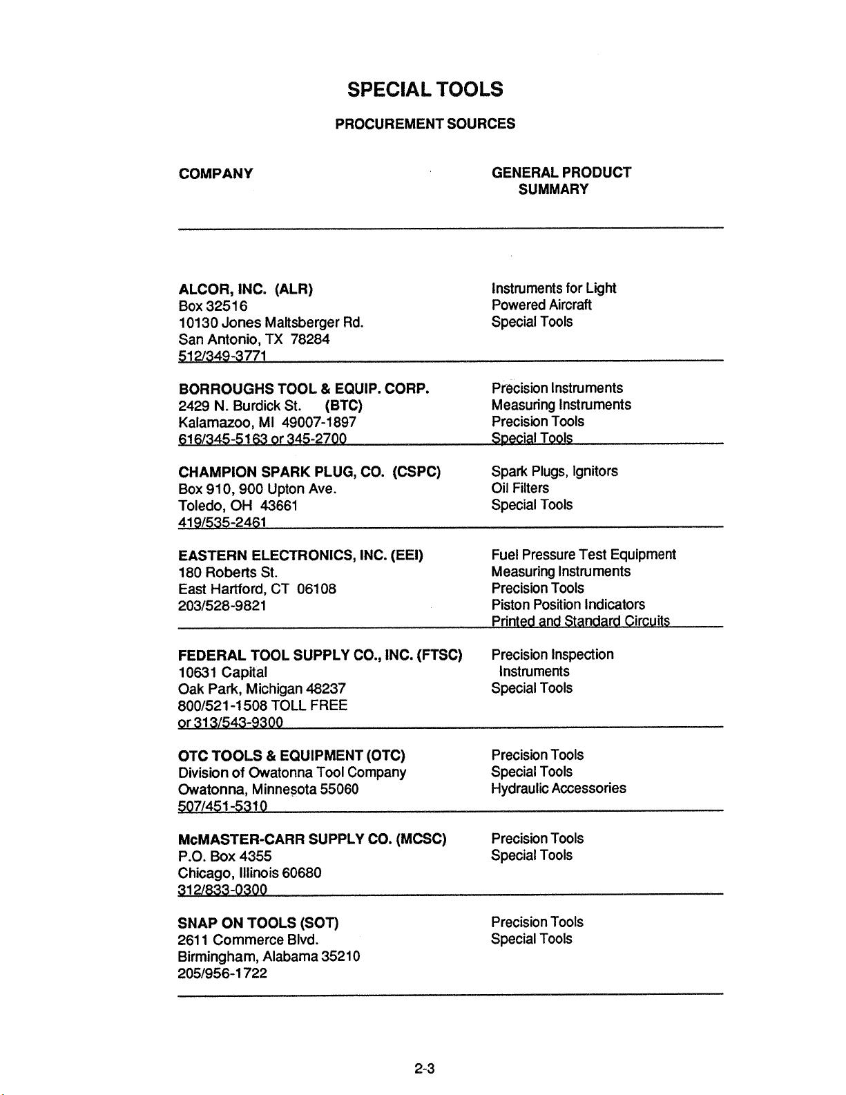
SPECIAL
PROCUREMENT SOURCES
TOOLS
COMPANY
ALCOR, INC. (ALR)
Box 325 1 6
10130 Jones
San Antonio, TX 78284
BORROUGHS TOOL & EQUIP. CORP.
N.
2429
Kalamazoo, MI 49007-1 897
51 61345-51
CHAMPION SPARK PLUG, CO. (CSPC)
Box 91 0,900
Toledo, OH 43661 Special Tools
41 91535-2461
EASTERN ELECTRONICS, INC. (EEI)
180 Roberts St. Measuring Instruments
East Hartford, CT 06108
2031528-9821 Piston Position Indicators
Maltsberger Rd.
Burdick St.
63
or 345-2700
Upton Ave.
(BTC)
GENERAL PRODUCT
SUMMARY
Instruments for
Powered Aircraft
Special Tools
Precision Instruments
Measuring Instruments
Precision Tools
S~ecial Tools
Spark Plugs, Ignitors
Oil Filters
Fuel Pressure Test Equipment
Precision Tools
Printed and Standard Circuits
Light
FEDERAL TOOL SUPPLY CO., INC. (FTSC)
10631 Capital Instruments
Oak Park, Michigan 48237
8001521 -1 508 TOLL
9r 31 31543-9300
OTC TOOLS & EQUIPMENT (OTC)
Division of Owatonna Tool Company
Owatonna, Minnesota 55060 Hydraulic Accessories
5071451 -531 0
McMASTER-CARR SUPPLY CO. (MCSC)
P.O. Box 4355 Special Tools
Chicago, Illinois 60680
SNAP ON TOOLS (SOT)
261 1 Commerce Blvd.
Birmingham, Alabama 3521 0
2051956-1 722
FREE
Precision Inspection
Special Tools
Precision Tools
Special Tools
Precision Tools
Precision Tools
Special Tools
Page 18
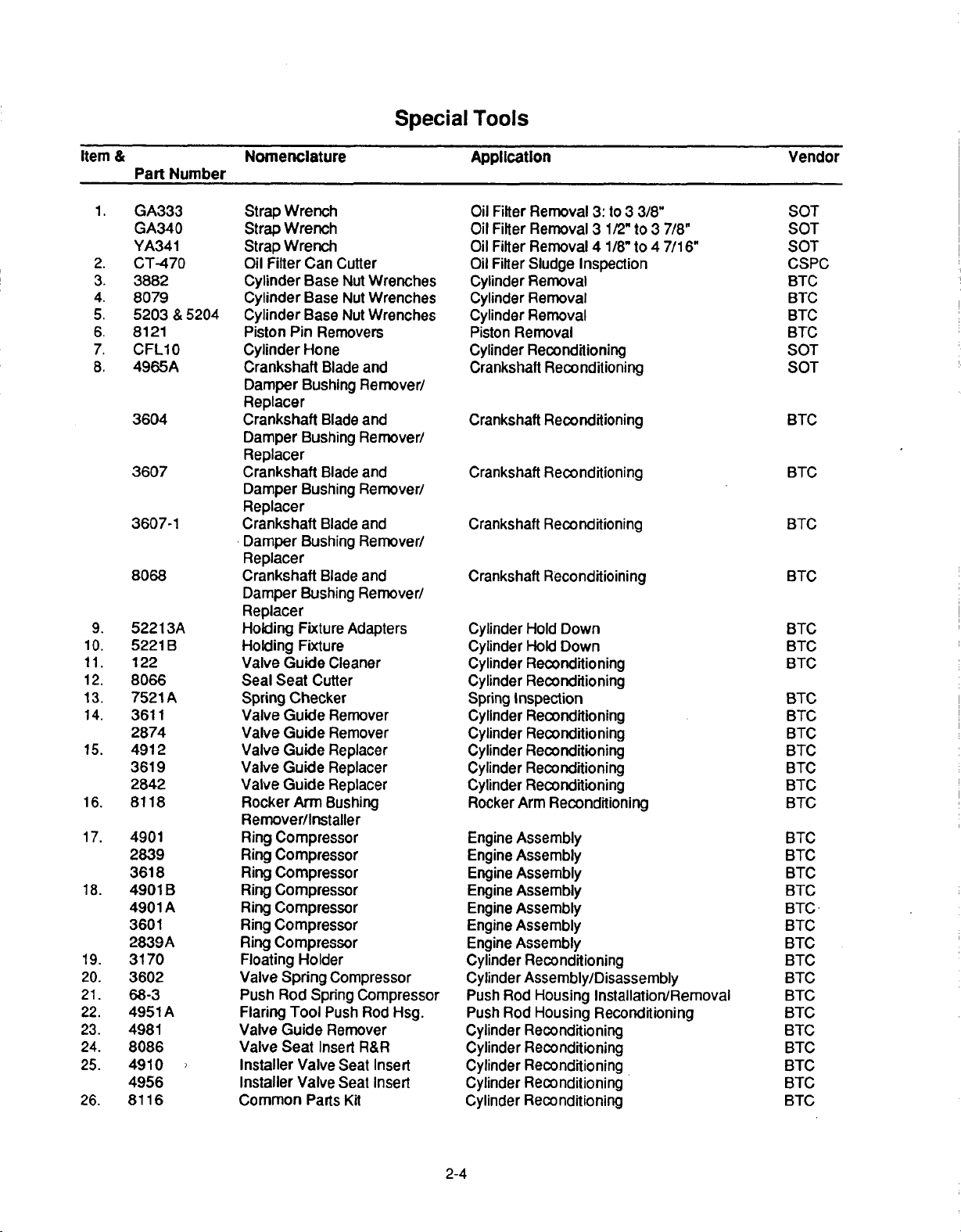
Item
1.
2.
3.
4.
5.
6.
7.
8.
9.
10.
11.
12.
13.
14.
15.
16.
17.
18.
19.
20.
21.
22.
23.
24.
25.
26.
&
Part
GA333
GA340
YA341
CT-470
3882
8079
5203
8121
CFLIO0
4965A
3604
3607
3607-1
8068
52213A
5221
122
80866
7521
3611
2874
4912
3619
2842
8118
4901
2839
3618
4901
4901
3601
2839A
3170
3602
68-3
4951
4981
8086
4910
4956
8116
Number
&
5204
B
A
B
A
A
Nomenclature
Strap
Wrench
Strap
Wrench
Strap
Wrench
Oil
Filter
Can
Cutter
Cylinder
Cylinder
Cylinder
Piston
Cylinder
Crankshaft
Damper
Base
Base
Base
Pin
Removers
Hone
Blade
Bushing
Nut
Nut
Nut
Replacer
Crankshaft
Damper
Blade and
Bushing Remover/
Replacer
Crankshaft
Damper
Blade
Bushing
Replacer
Crankshaft
Damper
Blade
Bushing
Replacer
Crankshaft
Damper
Blade
Bushing
Replacer
Holding
Holding
Valve
Seal
Spring
Valve
Valve
Valve
Valve
Valve
Rocker
Fixture
Fixture
Guide
Seat
Cutter
Checker
Guide
Guide
Guide
Guide
Guide
Arm
Adapters
Cleaner
Remover
Remover
Replacer
Replacer
Replacer
Bushing
Remover/Installer
Ring
Compressor
Ring
Compressor
Ring
Compressor
Ring
Compressor
Ring
Compressor
Ring
Compressor
Ring
Compressor
Floating
Valve
Push
Flaring
Valve
Valve Seat
Installer
Installer
Common
Holder
Spring
Rod
Spring
Tool
Guide
Insert
Valve
Valve
Parts
Compressor
Compressor
Push Rod
Remover
Seat
Seat
Kit
Special
Wrenches
Wrenches
Wrenches
and
Remover/
and
Remover/
and
Remover/
and
Remover/
Hsg.
R&R
Insert
Insert
Tools
Application
Oil
Filter
Removal
Oil
Filter
Removal
Oil
Filter
Removal 4 1/8"
Oil
Filter
Sludge
Cylinder
Cylinder
Cylinder
Piston
Cylinder
Crankshaft
Crankshaft
Crankshaft
Crankshaft
Crankshaft
Cylinder
Cylinder
Cylinder
Cylinder
Spring
Cylinder
Cylinder
Cylinder
Cylinder
Cylinder
Rocker
Engine
Engine
Engine
Engine
Engine
Engine
Engine
Cylinder
Removal
Removal
Removal
Removal
Reconditioning
Reconditioning
Reconditioning
Reconditioning
Reconditioning
Reconditioining
Hold
Hold
Reconditioning
Reconditioning
Inspection
Reconditioning
Reconditioning
Reconditioning
Reconditioning
Reconditioning
Arm
Assembly
Assembly
Assembly
Assembly
Assembly
Assembly
Assembly
Reconditioning
Cylinder Assembly/Disassembly
Push
Rod
Housing
Push
Rod
Housing
Cylinder
Cylinder
Cylinder
Cylinder
Cylinder
Reconditioning
Reconditioning
Reconditioning
Reconditioning
Reconditioning
3:
to 3 3/8"
3
1/2"
to 3 7/8"
to 4 7/16"
Inspection
Down
Down
Reconditioning
Installation/Removal
Reconditioning
Vendor
SOT
SOT
SOT
CSPC
BTC
BTC
BTC
BTC
SOT
SOT
BTC
BTC
BTC
BTC
BTC
BTC
BTC
BTC
BTC,
BTC
BTC
BTC
BTC
BTC
BTC
BTC
BTC
BTC
BTCBTC
BTC
BTC
BTC
BTC
BTC
BTC
BTC
BTC
BTC
BTC
2-4
Page 19
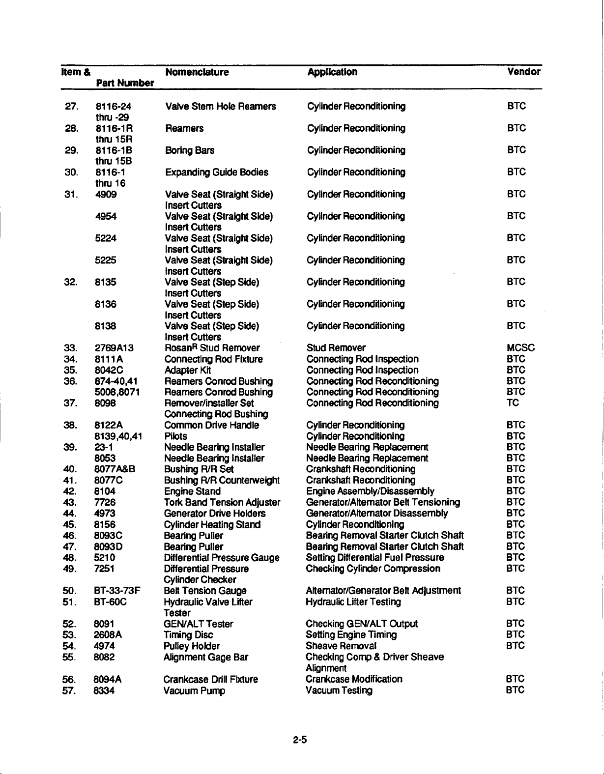
item
&
Part
Number
Nomenclature Application
Vendor
27.
28.
29.
30.
31.
32.
33.
34.
35.
36.
37.
38.
39.
40.
.41.
42.
43.
44.
45.
46.
47.
48.
49.
50.
51.
52.
53.
54.
55.
56.
57.
8116-24
thru
-29
8116-1iR
thru
15R
8116-l
B
thru
15B
8116-1
thru 1 6
4909 Valve
4954 Valve
5224
5225
8135
8136
8138
2769A1
8111
8042C Adapter
874-40,41
5008,8071
8098 Remover/installer
8122A
8139,40,41
23-1
8053 Needle
8077A&B
8077C
8104
7726
4973 Generator
8156
8093C
8093D
5210
7251
BT-33-73F
BT-60C
8091
2608A
4974
8082
8094A
8334
3
A
Valve
Stem
Hole
Reamiers
Reamers
Boring
Expanding
insert Cutters
Insert
Valve
Insert
Valve
Insert
Valve Seat (Step
Insert
Valve
Insert
Valve Seat
Insert
RosanR
Connecting
Reamers
Reamers
Connecting
Common
Pilots
Needle Bearing
Bushing
Bushing
Engine
Tork Band
Cylinder Heating
Bearing
Bearing
Differential
Differential Pressure
Cylinder Checker
Belt
Hydraulic
Tester
GEN/ALT Tester
Timing Disc
Pulley Holder
Alignment
Crankcase
Vacuum
Bars
Guide
Bodies
Seat
(Straight Side)
Seat (Straight Side)
Cutters
Seat
(Straight
Cutters
Seat
(Straight
Cutters
Side)
Cutters
Seat
(Step
Side)
Cutters
(Step
Side)
Cutters
Stud
Remover
Rod
Fixture
Kit
Conrod
Conrod
Drive
Bearing
R/R
R/R Counterweight
Stand
Tension
Drive
Puller
Puller
Tension
Valve
Gage
Pump
Bushing
Bushing
Set
Rod
Bushing
Handle
Installer
Installer
Set
Adjuster
Holders
Stand
Pressure
Gauge
Lifter
Bar
Drill
Fixture
Side)
Side)
Gauge
Cylinder
Cylinder
Cylinder
Cylinder
Cylinder
Cylinder Reconditioning
Cyiinder Reconditioning
Cylinder Reconditioning
Cylinder Reconditioning
Cylinder Reconditioning
Cylinder
Stud
Connecting
Connecting
Connecting
Connecting
Connecting
Cylinder
Cylinder
Needle
Needle
Crankshaft
Crankshaft
Engine
Generator/Altemator
Genierator/Alternator
Cylinder Reconditioning
Bearing Removal
Bearing Removal
Setting
Checking
Alternator/Generator
Hydraulic
Checking
Setting
Sheave
Checking
Alignment
Crankcase
Vacuum
Reconditioning
Reconditioning
Reconditioning
Reconditioning
Reconditioning
Reconditioning
Remover
Rod
Inspection
Rod
Inspection
Rod
Reconditioning
Rod
Reconditioning
Rod
Reconditioning
Reconditioning
Reconditioning
Beaning
Bearing
Assembly/Disassembly
Differential
Engine
Removal
Testing
Replacement
Replacement
Reconditioning
Reconditioning
Belt
Disassembly
Starter
Starter
Cylinder
Lifter
Testing
GEN/ALT
Timing
Camp & Driver
Modification
Clutch
Clutch
Fuel
Pressure
Compression
Belt
Output
Sheave
Tensioning
Adjustment
Shaft
Shaft
BTC
BTC
BTC
BTC
BTC
BTC
BTC
BTC
BTC
BTC
BTC
MCSC,
BTC
BTC
BTC
BTC
TC
BTC
BTC
BTC
BTC
BTC
BTC
BTC
BTC
BTC
BTC
BTC
BTC
BTC
BTC
BTC
BTC
BTC
BTC
BTC
BTC
BTC
2-5
Page 20
Item
&
Part
Number
Nomenclature
Application
Vendor
58.
59.
60.
61.
62.
63.
64.
65.
66.
67.
68.
69.
70.
71.
72.
73.
74.
75.
76.
77.
78.
79.
80.
81.
82.
83.
84.
85.
86.
87.
88.
89.
61-5
8094B
4918
8084
8065
504-1
4919
8054
445
8074
505
4978
8025
L423
5209
8048
8155
8117A
8087A&B
8165
8114
7912A
7710
1153
679
1035
927
1037
1079
1063
115-153
545-116
122-125
126-137
226-137
159-211
4903-1
thru
-5
4905
5129-1
thru
-5
5130
7232
4914-1H-S
thru 5HS
4943-1HS
thru 5HS
Pulley
Puller
Drill
Fixture
Spark
Plug
Insert
Replacer
Step
Cutter
Thru-Bolt
Step
Cutter
Thru-Bolt
Spark
Plug
Insert Tap
Spark
Plug
Insert
Remover
Slide
Hammer
Spark
Plug
Tap
RosanR
Stud
Scavenge
Drill
Crankcase Spitter
Propeller
Installer
Oil
Facer
Oil
Facer
Runout
Poilshing Tools
Crankshaft
Injector
and
Crankcase
Hex
Rotabroach
Puller
Puler
Puiler
Puller
Puller
Puller
Puller
Outside Micrometers
Dial
Blade
Screw
Screw
Depth
Reamers
Support
Reamers
Shaft
Reamers
Cylinder)
Reamer
Bushing
Reamer
Bushing
Reamers
Reamers
Lock Ring
Drivers
Pump
Fixture
Shaft
Oil
Pressure
Pressure
Installer
Drive
Bore
Bushing
Relief
Relief
Block
Set
Bearings
Nozzle Remover
thru
Cutters
Gages
Micrometers
Thread
Thread
Micrometers
Micrometers
Micrometers
Rocker
Boss
Rocker
(Straight
Rocker
Rocker
Valve
Guide
Valve
Guide
Installer
Drill
Seal
Spot
Spot
for
Bolt
Removers
Shaft
Arm
VIve
Shaft
Arm
Fixture
&
Boss
Boss
GEN/ALT
Journal
Cylinder
Crankcase
Crankcase
Cylinder
Cylinder
Multi
Cylinder
Stud
Stud
Crankcase
Crankcase
Crankcase
Installation
Removal
holes
Removal
holes
Crankshaft
Crankshaft
Injector
Engine
Loosening
Hole
Removal
Removal
Removal
Removal
Removal
Removal
Removal
Dimensional Inspection
Dimensional Inspection
Dimensional
Dimensional
Dimensional
Dimensional Inspection
Cylinder
Rocker
Cylinder
Cylinder
Rocker
Cylinder
Cylinder
Sheave Removal
Bearing
Reconditioning
Reconditioning
Reconditioning
Use
Reconditioning
Installation
Installation
of
of
Removal & Replacement
Disassembly
Cutting
of
of
of
of
of
of
of Press
Reconditioning
Arm
Reconditioning
Reconditioning
Arm
Reconditioning
Reconditioning
Modification
Modification
Modification
Modification
Squirt
Nozzle
Separation
of Seal
Inspection
Reconditioning
Tubing
over Propf
surface
surface
Press
Press
Press
Press
Press
Press
Inspection
Inspection
Inspection
Reconditioning
Reconditioni
Material
Material
"B*
Nuts
Fit
Parts
Fit
Parts
Fit
Parts
Fit
Parts
Fit
Parts
Fit
Parts
Fit
Parts
Replacement
lange
around
around
ng
BTC
BTC
BTC
BTC
BTC
BTC
BTC
BTC
BTC
BTC
BTC
BTC
BTC
BTC
BTC
BTC
BTC
BTC
BTC
BTC
BTC
BTC
BTC
OTC
OTC
OTC
OTC
OTC
OTC
OTC
FTSC
FTSC
FTSC
FTSC,
FTSC
FTSC
BTC
BTC
BTC
BTC
BTC
BTC
BTC
2-6
Page 21
Item
&
Part
Number
Nomenclature
Application
Vendor
90. 2847-2Cp
4913-1
3606-CP
2847-1
2847-2HP
4913-1HP
3606-HP
28471
HP
91.
92.
93.
94.
95.
96.
97.
98.
99.
100.
101.
102.
103.
104.
105.
2684
2686
2689
2693
4104
2848-1
2848-2
3615
7308
52.030-006
600R-30
647
E100
Model
29
11-9110-1
Model
E25
Model
El
Model
E5
646953
85328
85329
Cp
Cp
0
Reamer
Reamer (Carbide
Reamer (Carbide
Reamer
Reamer
Reamer
Reamer
Reamer
Reamer
Reamer
Reamer (Square
Reamer
Reamer
Plug
Plug
Plug Gage
Dial
Precision
Inside Measuring
Alternator Analyzer
Regulator
Aftemnator/Regulator/
Battery
Voltage
Magneto
Timing
Cold
Hi-Voltage
Master
Alcor
Unit
Alcor
Unit
(Carbide
(Carbide
(High
(High
(High
(High
(Square
(Square
(Square
(Square
Gage
Gage
Thickness
Vernier
Tester
Tester
&
Circuit
Timing
Indicator
Cylinder Tester
Tester
Orifice Tool
Portable
Portable
Tipped)
Tipped)
Tipped)
Tipped)
Speed
Speed
Speed
Speed
Shank)
Shank)
Shank)
Shank)
Shank)
Gage
Calipers
Instrument
Tester
Light
Digital
Digital
Steel)
Steel)
Steel)
Steel)
Voltage
EGT
CHT
Cylinder
Cylinder Reconditioning
Cylinder
Cylinder
Cylinder
Cylinder
Cylinder
Cylinder
Cylinder
Cylinder
Cylinder
Cylinder
Cylinder Reconditioning
Valve
Valve
Valve
Dimensional
Dimensional
Dimensional
Charging
Charging
Electrical
Set
Set
Cylinder
Test
Cylinder
Engine
Engine Test
Reconditioning
Reconditioning
Reconditioning
Reconditioning
Reconditioning
Reconditioning
Reconditioning
Reconditioning
Reconditioning
Reconditioning
Reconditioning
Guide
Inspection
Guide
Inspection
Guide
Inspection
Inspection
Inspection
Inspection
System
System
System Test
Engine
Engine
Timing
Timing
Firing
Improperly
Ignition
Cable
Compression
Test
Test
Test
Continuity
Test
BTC
BTC
BTC
BTC
BTC
BTC
BTC
BTC
BTC
BTC
BTC
BTC
BTC
BTC
BTC
BTC
FTSC
FTSC
FTSC
EEl
EEl
EEl
KTC
EEl
EEI
KTC
BTC
ALR
ALR
2-7
Page 22
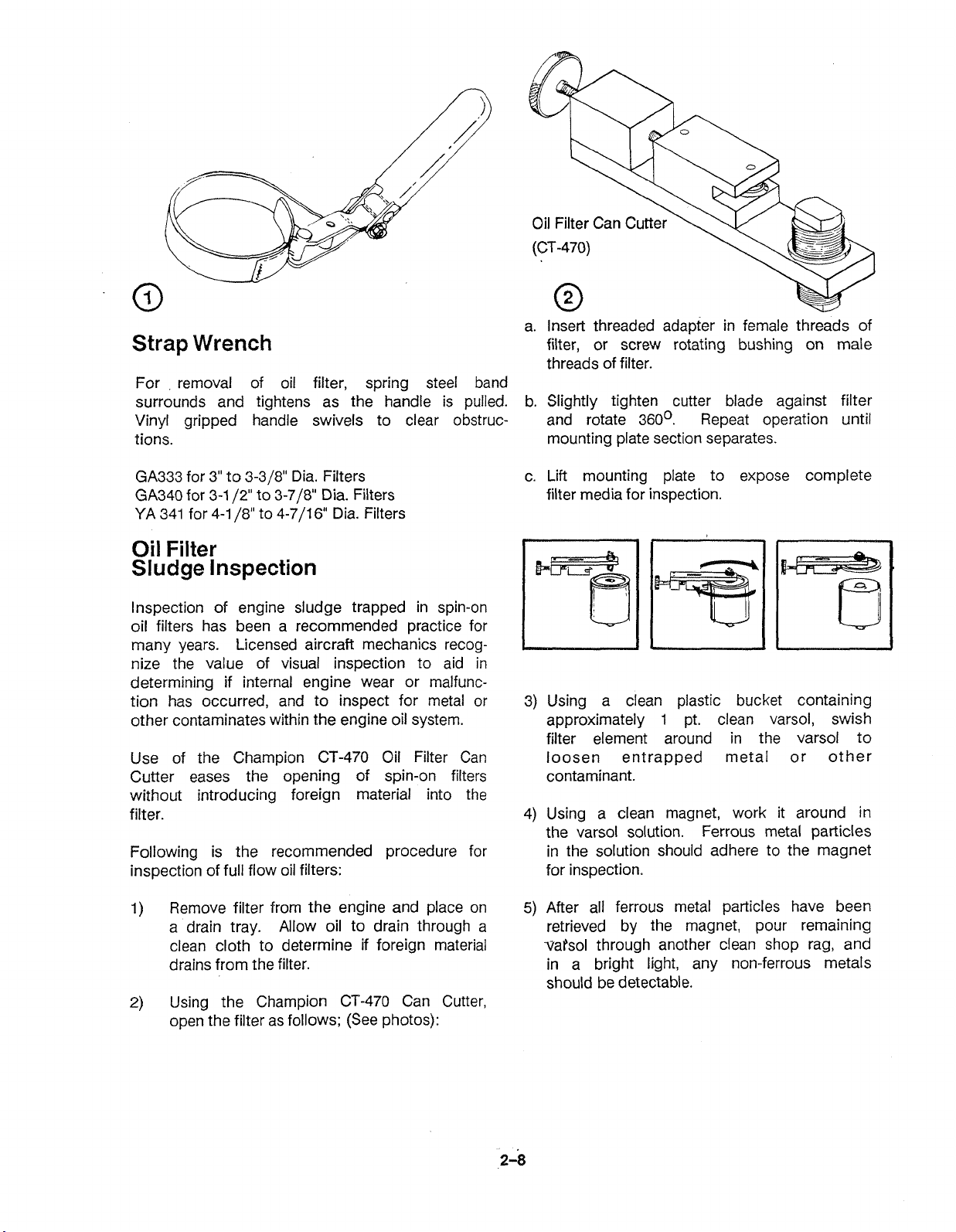
a. Insert threaded adapter in female threads of
Strap
For removal of oil filter, spring steel band
surrounds and tightens as the handle is pulled. b. Slightly tighten cutter blade against filter
Vinyl gripped handle swivels to clear obstruc- and rotate
tions. mounting plate section separates.
GA333 for 3" to 3-3/8" Dia. Filters c. Lift mounting plate to expose complete
GA340 for 3-1
YA 341 for 4-1
Oil
Sludge
lnspection of engine sludge trapped in spin-on
oil filters has been a recommended practice for
many years. Licensed aircraft mechanics recog-
nize the value of visual inspection to aid in
determining if internal engine wear or malfunction has occurred, and to inspect for metal or
other contaminates within the engine oil system.
Use of the Champion CT-470 Oil Filter Can
Cutter eases the opening of spin-on filters
without introducing foreign material into the
filter.
Following is the recommended procedure for
inspection of full flow oil filters:
Wrench
Filter
Inspection
/2"
to 3-7/8" Dia. Filters
/8"
to 4-7/16" Dia. Filters
filter, or screw rotating bushing on male
threads of filter.
360'. Repeat operation until
filter media for inspection.
3) Using a clean plastic bucket containing
1
approximately
filter element around in the varsol to
loosen entrapped metal or other
contaminant.
4)
Using a clean magnet, work it around in
the varsol solution.
in the solution should adhere to the magnet
for inspection.
pt. clean varsol, swish
Ferrous metal particles
Remove filter from the engine and place on
1)
a drain tray. Allow oil to drain through a
clean cloth to determine if foreign material
drains from the filter.
2)
Using the Champion CP-470 Can Cutter,
open the filter as follows; (See photos):
5)
After all ferrous metal particles have been
retrieved by the magnet, pour remaining
vatsol through another clean shop rag, and
in a bright light, any non-ferrous metals
should be detectable.
Page 23
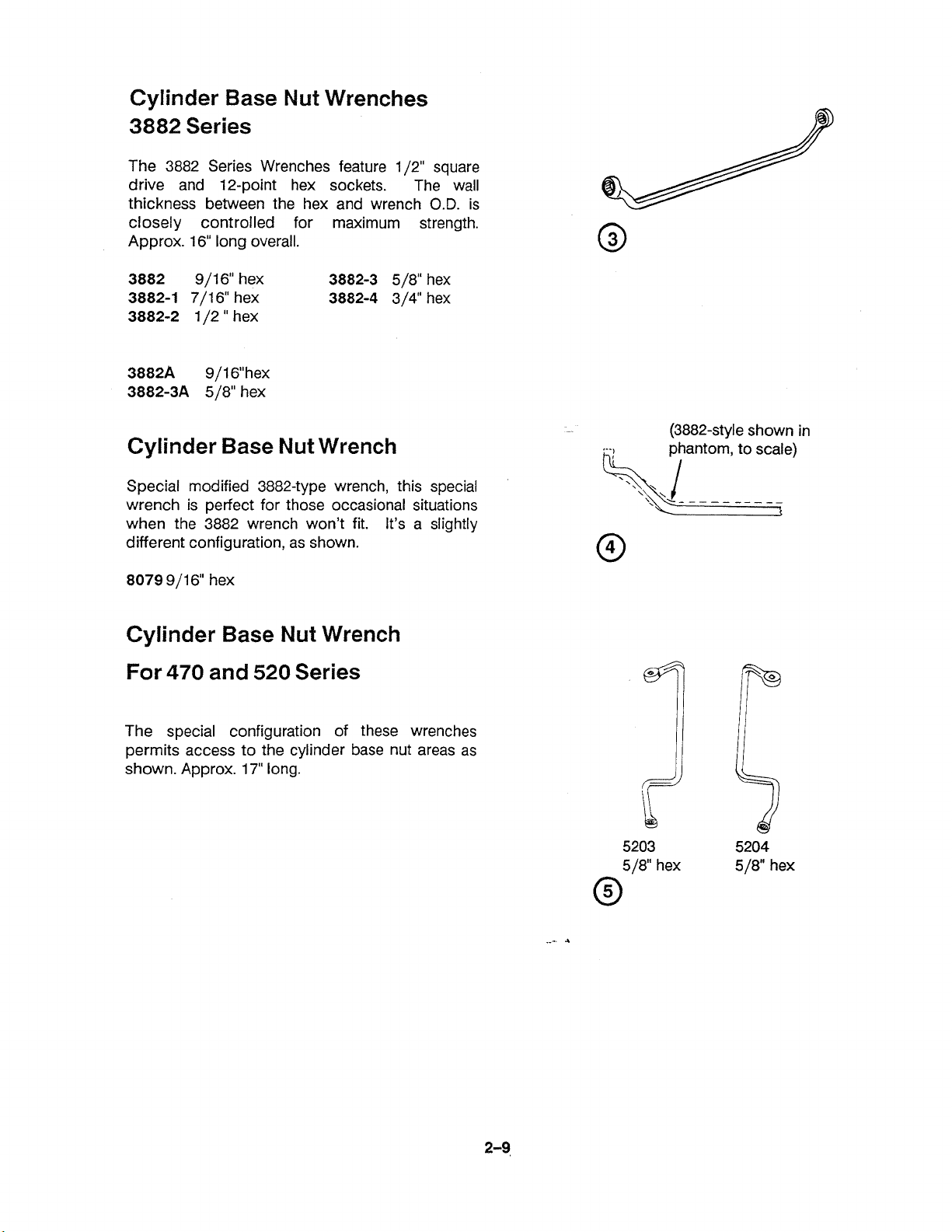
Cylinder Base
Nut
Wrenches
3882 Series
The 3882 Series Wrenches feature 1/2" square
drive and 12-point hex sockets. The wall
thickness between the hex and wrench
closely controlled for maximum strength.
Approx. 16" long overall.
O.D.
is
3882
3882-1
3882-2
3882A
3882-3A
Cylinder Base
Special modified 3882-type wrench, this special
wrench is perfect for those occasional situations
when
different configuration, as shown.
8079
Cylinder Base
9/16" hex
7/16" hex
1 /2 " hex
9/16"hex
5/8" hex
Nut
the 3882 wrench won't fit. It's a slightly
9/16" hex
Nut
3882-3
3882-4
Wrench
Wrench
5/8" hex
3/4" hex
For 470 and 520 Series
(3882-style shown in
The special configuration of these wrenches
permits access to the cylinder base nut areas as
shown. Approx. 17" long.
5203 5204
5
18" hex
5
18" hex
Page 24
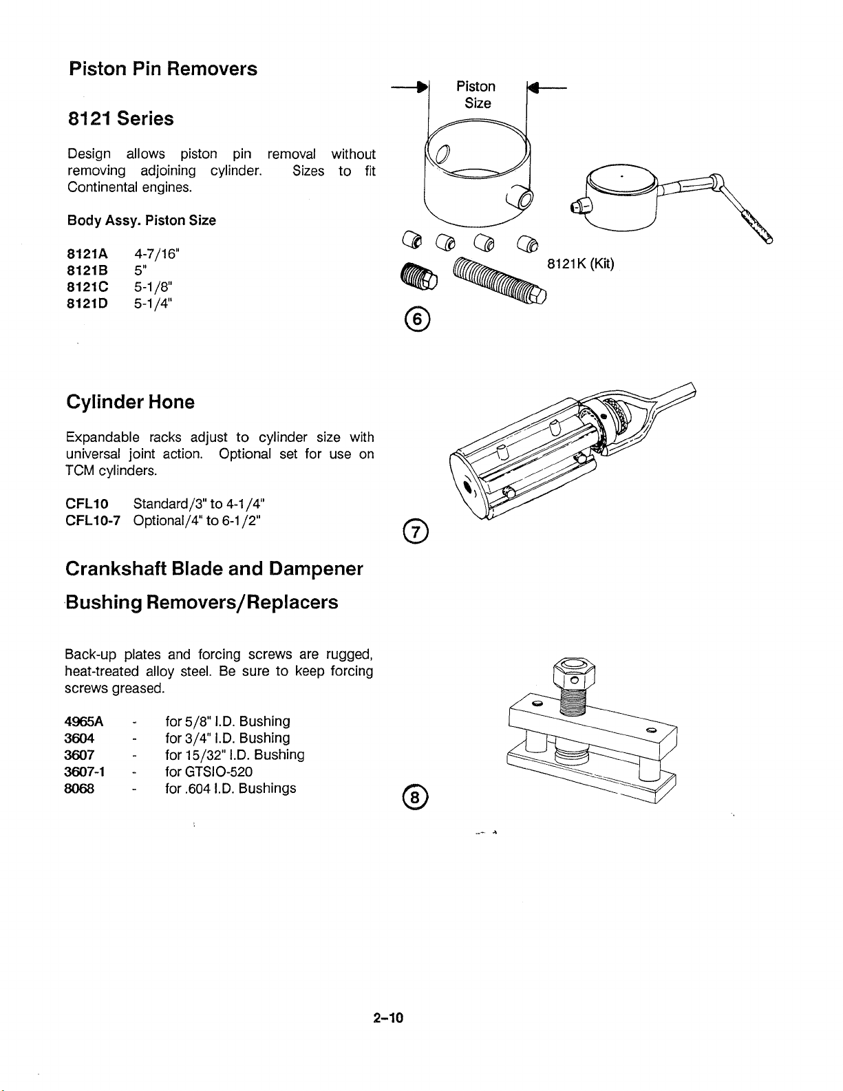
Piston Pin Removers
8121
Design allows piston pin removal without
removing adjoining cylinder. Sizes to fit
Continental engines.
Body Assy.
Series
Piston
Size!
Cylinder Hone
Expandable racks adjust to cylinder size with
universal joint action. Optional set for use on
TCM cylinders.
81
21
K (Kit)
Crankshaft Blade and Dampener
Back-up plates and forcing screws are rugged,
heat-treated alloy steel. Be sure to keep forcing
screws greased.
4965A
3604
3607
3607-1
8068
-
for 518" I.D. Bushing
-
for 314" I.D. Bushing
-
for 15/32" I.D. Bushing
-
for GTSIO-520
-
for
,604
I.D. Bushings
Page 25
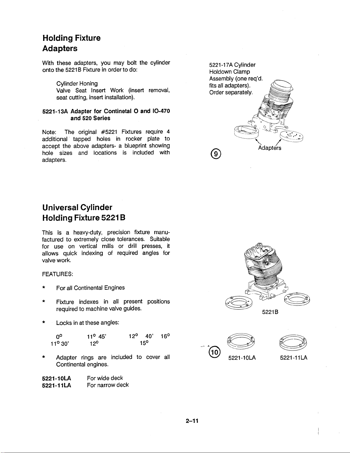
Holding Fixture
Adapters
With these adapters, you may bolt the cylinder
onto the 5221
Cylinder Honing
Valve Seat Insert Work (insert removal,
seat cutting, insert installation).
5221-13A Adapter for Continetal 0 and 10-470
Note: The original #5221 Fixtures require
additional tapped holes in rocker plate to
accept the above adapters- a blueprint showing
hole sizes and locations is included with
adapters.
B
Fixture in order to do:
and 520 Series
4
Universal Cylinder
Holding Fixture
5221
B
-1
7A
5221
t-loldown Clamp
Assembly (one req'd.
fits all adapters).
Order separately.
Cylinder
This is a heavy-duty, precision fixture manufactured to extremely close tolerances. Suitable
for use on vertical mills or drill presses, it
allows quick indexing of required angles for
valve work.
FEATURES:
*
For all Continental Engines
*
Fixture indexes in all present positions
required to machine valve guides.
*
Locks in at these angles:
*
Adapter rings are included to cover all
Continental engines.
5221-10LA
5221-1 1LA
For wide deck
For narrow deck
Page 26
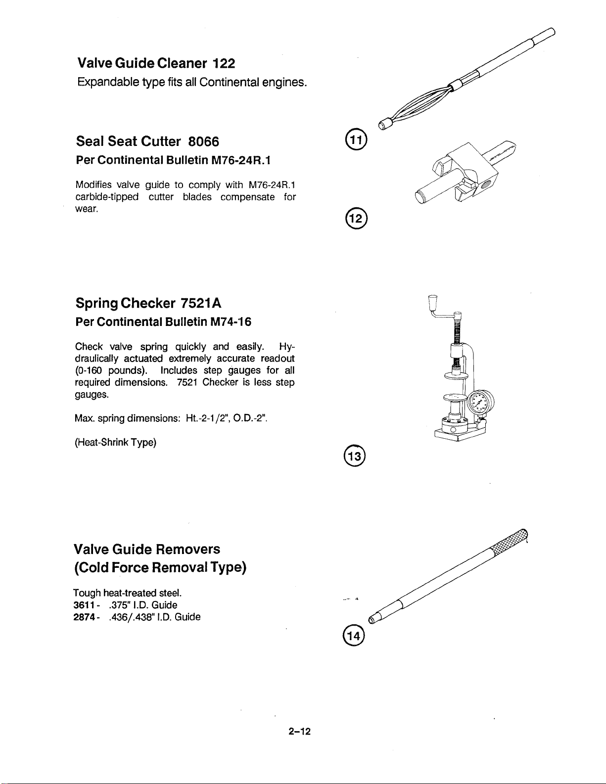
Valve Guide Cleaner 122
Expandable type fits all Continental engines.
Seal Seat Cutter
Per Continental Bulletin
Modifies valve guide to comply with
carbide-tipped cutter blades compensate for
wear.
Spring Checker 7521
Per Continental Bulletin
Check valve spring quickly and easily. Hy-
draulically actuated extremely accurate readout
(0-160
required dimensions. 7521 Checker is less step
gauges.
Max.
pounds). Includes step gauges for all
spring dimensions: Ht.-2-1/2", 0.D.-2".
8066
M76-24R.1
M76-24R.1
A
M74-16
(Heat-Shrink Type)
Valve Guide Removers
(Cold Force Removal 'Type)
Tough heat-treated steel.
361
1
-
.375"
I.D. Guide
2874 - .436/.438"
1.D.
Guide
Page 27
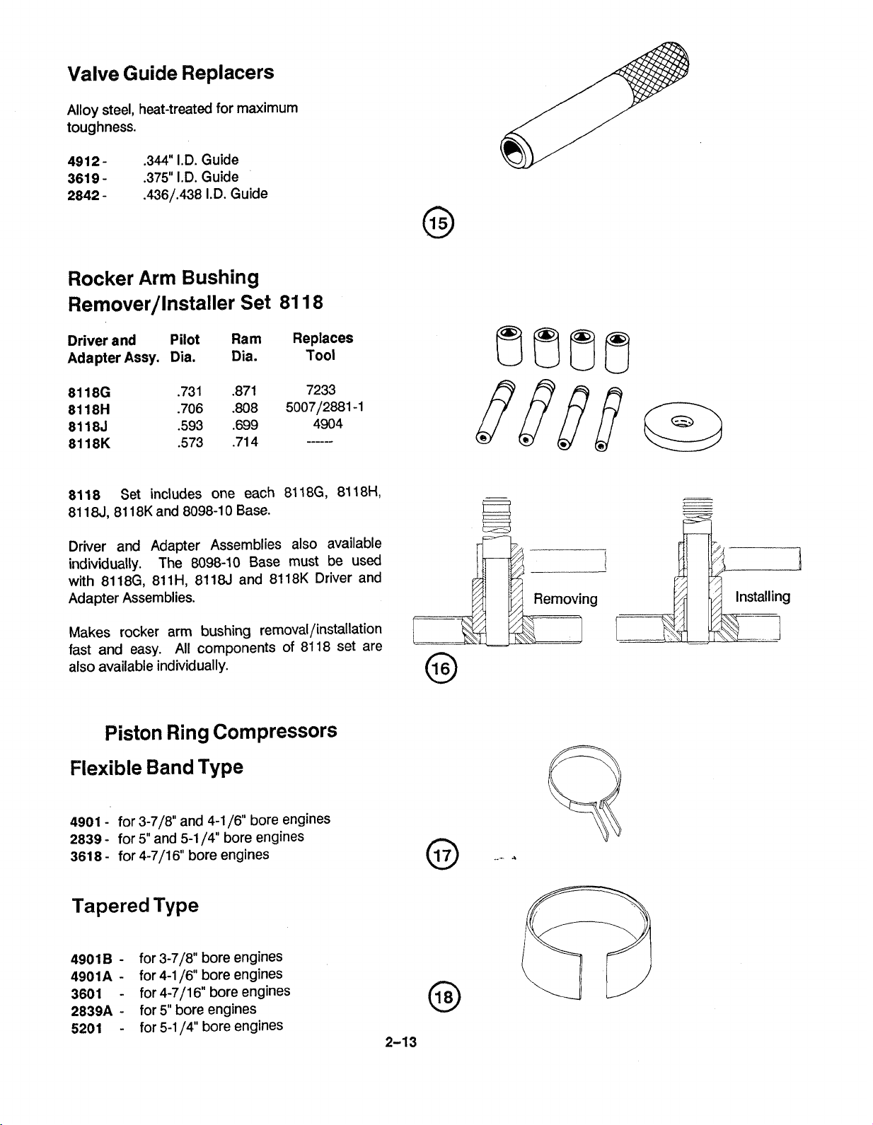
Valve Guide Replacers
Alloy steel, heat-treated for maximum
toughness.
4912361 9
2842
.344" I.D. Guide
-
.375" 1.D. Guide
-
.436/.438 I.D. Guide
Rocker Arm Bushing
Remover/lnstaller Set 81 18
Driver and
Adapter
8118
81 184 81 18K and 8098-1 0 Base.
Driver and Adapter Assemblies also available
individually. The 8098-10 Base must be used
with
Adapter Assemblies.
Assy.
Set includes one each 81 18G, 81 18H,
81 18G, 81 1H, 8118J and 81 18K Driver and
Pilot
Dia.
Ram Replaces
Dia. Tool
Makes rocker arm bushing
fast and easy. All components of 81 18 set are
also available individually.
removal/installation
Piston Ring Compressors
Flexible Band
4901
-
for 3-718" and 4-1 16" bore engines
2839
-
for
5"
and 5-1 14" bore engines
361 8
-
for 4-7/16 bore engines
Type
Tapered Type
4901
B
-
for 3-718" bore engines
4901A
3601
2839A
5201
-
for 4-1 16" bore engines
-
for 4-711 6" bore engines
-
for 5" bore engines
-
for 5-1 14" bore engines
Page 28

31 70 - Floating holder
No. 3 Morse male, compensates for misalignment
between reamer and work. Provides
unrestricted float.
Valve Spring
Compressor 3602
Adjustable type works on all Continental
engines.
Hook installs on rocker shaft (or on special
rocker nut furnished) and c-shaped collar
compresses spring to allow keeper removal.
stressed parts are heated-treated steel. Handle
18"
is approx.
long for good leverage.
All
Push Rod Spring
Compressor 68-3
For compressing and holding push rod springs
on all engines with spring loaded tubes. The
68-3
compresses the spring, which can then be
removed with furnished clips.
Eliminates wiring springs together- to install,
simply insert spring then pull off clip!
instructions.
Includes
Flaring Tool for Push
Rod Housing 4951
For A
Balls rotate inside housing, expanding it into
aluminum boss.
81
C Series - expanding ball type tool.
A
Valve Guide Remover 4981
Removes guides by heat-shrink method.
Cylinder is heated to
water to guide bore.
hammer removes guide.
included) supplies the low water pressure
required to cool the guides for easy removal.
Replacement guide is usually same size as the
one removed.
475O~, then tool injects
A
light tap with the
A
water reservoir (not
slide
Page 29
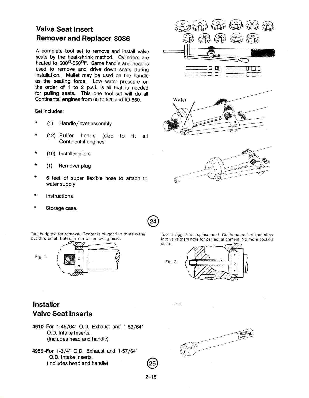
Valve Seat Insert
Remover and Replacer
A
complete tool set to remove and install valve
8086
seats by the heat-shrink method. Cylinders are
heated to
500~-550°F. Same handle and head is
used to remove and drive down seats during
installation. Mallet may be used on the handle
as the seating force. Low water pressure on
the order of
1
to 2 p.s.i. is all that is needed
for pulling seats. This one tool set will do all
Continental engines from 65 to 520 and 10-550.
Set includes:
*
(1) Handle/lever assembly
*
(12) Puller heads (size to fit all
Continental engines
*
(1
0)
Installer pilots
*
(1)
Remover plug
*
6 feet of super flexible hose to attach to
water supply
*
Instructions
*
Storage case.
Tool is rigged for removal. Center
out thru small holes in rim of
Fig.
1.
is
plugged to
removina head.
"
route water
Installer
Valve Seat lnserts
491 0 -For 1-45/64" O.D. Exhaust and 1-53/64"
O.D. Intake lnserts.
(Includes head and handle)
Tool
is
rigged for replacement. Guide on end of tool slips
into valve stem hole for
seats
Flg
2
perfect alianment.
No
more cocked
4956-For
1-3/4" O.D. Exhaust and 1-57/64
O.D. lntake Inserts.
(Includes head and handle)
Page 30
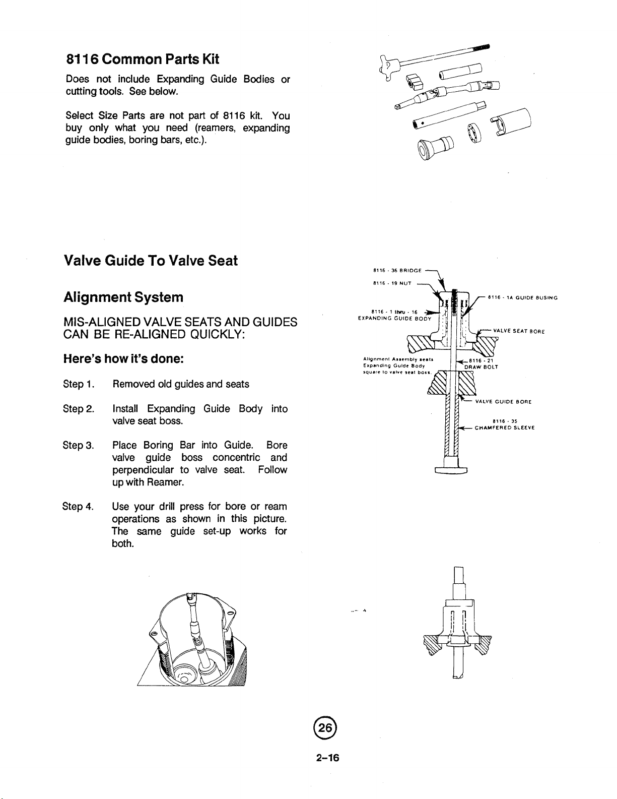
81
16
Common
Parts Kit
Does not include Expanding Guide Bodies or
cutting tools. See below.
part
of
81
16
kit.
Select Size Parts are not
You
buy only what you need (reamers, expanding
guide bodies, boring bars, etc.).
Valve Guide
To
Valve Seat
Alignment System
MIS-ALIGNED VALVE SEATS AND GUIDES
BE
CAN
Here's how it's done:
Step
Step
Step
Step
RE-ALIGNED QUICKLY:
Removed old guides and seats
1.
2.
Install Expanding Guide Body into
valve seat boss.
3.
Place Boring Bar into Guide. Bore
valve guide boss concentric and
perpendicular to valve seat. Follow
up with Reamer.
Use your drill press for bore or ream
4.
operations as shown in this picture.
The same guide set-up works for
both.
8116.
36
BRIDGE
8116 . 19 NUT
11116 - 1
EXPANDING GUIDE
1b.
16
80
---,
8116. 1A GUIDE BUSING
LVE SEAT BORE
GUIDE BORE
ALVE
CHAMFERED SLEEVE
Page 31

Valve Stem Hole Reamers
(T3kes the place
of
2847,3606
81
491
3
Series reamers).
Tool No. Hole Dia.
81 16.24 .344
Boring Bars Reamers
Made
of
ground.
high speed
M2
tool steel, precision
Reamers
Tool No. Hole Dia.
Valve Guide Boss. (Takes place of
491
4
and 4943 Series reamel s).
Boring Bars
Tool No.
Hole Dia.
(*Example: Use
Reamer
6R
Expanding
Guide
Bodies
81
16-6B Boring Bar to bore hole to
to
561
dia.)
Expanding Minimum Maximum
Bodv No. Retracted Dia. Expanded Dia.
8116-1
8116-2
81 16-3
81 16-4
8116-5
81
16-6
81 16-7
81 16-8
81 16-9
8116-10
8116-11
8116-i2
81 16-13
81 16-14
8116-15
8116-16
.555,
then finish with 8116-
Page 32

Valve
Seat
Insert
Straight Side - Non Step
Cutters
Part
No.
Use
4909-8 lnt
4909-9 Int
4909-12
4-13 Exh
4954-5 Int
4954-8 Int
4954-9 Int
4954-10
4954-1 1 Int
4954-12
4954-13 Exh
4954-14 Exh
4954-15 Exh
49851 Int
49852 Int
4985-3 Int
4985-4 Int
Exh
Int
Exh
Finish
Dim.
O.S.
WARNING!
Measure New Insert
select proper cutter.
Straight Side
Cutters
Finish
Part
No.
Use
Dim.
Q&.
4985-5 Int 2.140 .030"
4985-6
4985-7 Exh 1.664 .010
4985-8 Exh 1.669 .015"
4985-9 Exh 1.674
4985-10 Exh 1.684 ,030"
5224-5
5224-10 Int 2.527 .010
5224-15
5224-20 Int 2.537 .020"
5224-30
5225-5 Exh 1.793 .005"
5225-10 Exh 1.798 .O10"
5225-15 Exh 1.808 .015"
5225-20 Exh 1.808 SO20
5225-30 Exh 1.818
Exh 1.669 ,005"
.OW
Int 2.522 .005
Int 2.523 .015
Int 2.547
-030"
.03*
Part
O.D.
and then
Small
No.
Diameter Diameter Part
--
Large
STD
.005
.010"
.015"
.OW'
.w
STD
,005
.O1on
Step Side
Cutters
Small
No.
Diameter Diameter 8.S.
2.070
2.070
2.070
2.632 STD
2.632
2.632 .010
2.632
2.632
2.632 .ON"
Large
,015
.O2OM
.OW
.05"
.015"
.ow
Rosan@
Stud
Remover
This stud remover is for use in extracting studs
from cylinder assemblies using
~osan~type
Studs.
Using the hammer, drive the stud driver
over stud
contact with the cylinder head
(2)
as far as possible without making
(3).
Using the
(1)
ratchet or pull handle, apply a firm, constant
pressure in the clockwise (tightening) direction,
the serration
(4)
on the stud will strip.
When
the stud gives, reverse the ratchet and back
the stud out until there are three threads still
engaged in the lock ring
with the
driver still attached, up, down and
(5).
Move the stud
sideways. The lock ring will pop out of the
cylinder without damaging
is Part No.
2769A13.
it.
The stud driver
2
A
3
Page 33

Connecting Rod Reaming and
Alignment Checking Fixture
With these precision tools, it's easy to check
connecting rods (without bushings) for
alignment and
The 81 11A
well as one (or more) of the Adapter Kits
described below. The 811
high-carbon steel base (hardened and ground for
long life); retaining collar, cap (for connecting
rod) and wing nut.
The
81
11A Base/Retainer
Adapter Kits as described below.
warpage.
Base/Retainer Kit is required as
1A Kt includes the
Kit
fits the following
Adapter Kits
These kits contain the indicator gauge assembly,
which as a dial indicator reading in ten-thou-
sandths of an inch (.0001"). The gauge body is
lapped into the mating bushing for accurate
readings. Instructions are included.
Adapter Kits
8042C
8072C
for 520-470-E Series 1.125"
1
.OOM
&
for 0-200, 0300,360
.922"
@
Q
@
BasejRetainer Kit 81 1 1 A
Complete tool combining
81
11A Base with one of the 3
listed adapter
checking rod for alignment.
Q
a
kits shown
Reamers, Connecting Rod Bushing
High-speed steel reamers with 3/4" diameter
pilot. Use with
proper Adapter
874-40
874-41
5008
8071
.920" Roughing
.923 Finishing
1.1 26" Finishing
1
.OOOM
8111A Base/Retainer Kit and
Kit
as shown above.
use together
Finishing
@
Complete tool
using same adapters
shown above with piston
pin reamer. See at left
for proper reamer to use
Page 34

Universal Connecting
Rod
Bushing
Remover and Installer Set
Complete set for removing and installing con-
necting rod bushings for Continental Support
bushing reverses for either installing or
removing.
8098 Complete Set
8098-10
Driver and
Adapter Assy.
(Above Driver and Adapter Assemblies also
available individually).
Base
Pilot
Dia.
Includes:
Ram Replaces
Dia.
8098
Tool
-+-
8098-10
(Included)
Bare
Common Drive Handle
This Drive Handle fits all pilots and cutters,
and
it
features positive pin drive as shown.
(Combination of Morse taper and pin drive
eliminates any slippage between handle and
cutter.)
By using the
below, you may choose to pilot into valve stem
hole or valve guide boss.
8122A with the proper pilot from
81
22A
Pilots
All pilots are hardened and precision ground for
accuracy. Two choices- pilot into valve stem
hole or valve guide boss.
No.
1-
Pilot Choice
(On
new installations only)
Part No. Pilot Dia.
CAUTION:
Pilot lnto Valve Stem Hole
DO NOT USE ON
WORN
GUIDES!
i
81
22A Common
Drive Handle
This handle fits all
pilots and cutters (also
fiis
your old cutters).
Cutter
Pilots
..-
4
,
Pilot
Choice
Part No. Pilot Dia. Application Part No. Pilot Dia. Application
.-
-
8123
8124
8125
8126
8127
8128 ,560
,530 Standard 8129
,535
,540 Oversize ,010 8131
,545
,550 Oversize ,020 8133
"-2
No.
2
-
Pilot
lnto
Valve
--
Oversize ,005 8130
Oversiz~O15 8132 ,639
Oversize ,030
8134
Guide
,624
529
,634 Oversize ,010
,644 Oversize .020
,654 Oversize .030
Standard
Oversize .005
Oversize .015
Boss
Page 35

Needle Bearing Installers
Precisely machined to make bearing installation
fast.
23-
1
8053
562" pilot
.75OU pilot
Hydraulic Crankshaft Dampener
Bushing
Remover/Replacer Sets
8077A and 80776
Remove and
fraction of the time hydraulically!
strokes of the pump handle removes or installs
bushing with very little effort. Small actuating
head
fits in and around the crankshaft. Once
the bushing is removed (or installed), a turn of
the valve returns actuator for another cycle.
8077A
10,000
cylinder; 3-ft. long Rex hydraulic hose; all
adapters to fit 0-300 and 360, 470 and 520
Series.
80778
Items shown above in 8077A except no
hydraulics are furnished. The actuator head has
114"
hydraulic hose.
includes:
p.s.i. pump and cylinder; 5-ton output
(less hydraulics) includes:
NPT female port for connecting to your
replace crankshaft bushings in a
A
few
Counterweight Bushing
~emover/lnstaller
8077C
Positive guide of all components assures perfect
alignment. Includes adapters for
470 and 520 Series engines.
0-300, 360,
6%~~
,
,,
J-,
......
ii
Page 36

All
Position Engine Stand
Assem
Transportation
Designed to save time on the overhaul floor.
Minimum attaching hardware allows complete
engine accessibility.
Positive frame rotation
number of positions simply by releasing handle.
Engine mounting plate also rotates
locks in place with heat-treated lock pin.
Flange holder is predrilled to accept
tinental
mount non-flanged crankshafts. Shipping
weight
bl
y-Disassem
erigines. Threaded adapters included to
400
Ibs.
bly
81
04
(360~) locks in infinite
360O and
all Con-
Tork Band Tension Adjuster
7726
Adjust belt tension without damage to
nents. Use on alternators, compressors, etc.
Allows grabbing difficult round components.
compo-
Generator Drive Holder
Hold drive gear for torquing or removing
retaining nut.
4973
4973A
2.600" dia.
2.51
0" dia.
..-
4
Page 37

Cylinder Heating Stand
In just 8-10 minutes, you can heat 2 cylinders
simultaneously to
a
time (each tip is separately controlled).
at
Included with the 8156 Cylinder Heat Stand:
(2) Tips
(2)
36"
Propane Hoses wlfittings
(1)
Propane Regulator
(2) Controls
(1)
Y-Connector
(1) Stand
(2) Cylinder Risers
All screws, nuts and washers needed; and
instructions.
600°F. Or, you can heat one
81
56
20
Tip:
/
Ib.
\
Propane
Y-Connector
Tank
Blind Needle Bearing
8093C
Puller
Use to remove 5f8"
and 520 Series engines. Use with 8054 Slide
Hammer.
I.D.
needle bearings in 470
Starter Clutch Shaft
Bearing Pullers
80930
for removing
314"
I.D. bearings.
Use
with
8054
Slide
Harnmer
Page 38

Differential Pressure Gauge
For turbo superchargers. A rugged, high
precision gauge needed to set differential fuel
measures. 50-0-50 psi,
pipe connection.
4-1/2" dia. face,
521
0
1/4"
Differential Pressure 7251
Cylinder Checker
Use standard shop air pressure to check
condition of rings, cylinder walls and valves.
Belt Tension Gauge BT-33-73F
(TSIO-520-BE uses BT-33-89P)
Set belt tension quickly and accurately to
ensure maximum belt and bearing life. The
proper belt-tension eliminates slippage and
increases efficiency of belt-driven opponents.
Compact- only 3
areas. Easy to use- just apply gauge to belt,
release ball handle and read tension on rotating
dial.
Calibrated for A-section V-belts
top width) and K-section
belts. Range 30 to 180 Ibs. and
newtons (dual scale).
1/4" wide to fit in crowded
(3/8
to
1
/2"
(4,5,
and 6 rib) poly-V
130
to 800
Hydraulic Valve BT-6OC
Lifter Tester
For checking bleed down rate on hydraulic
lifters. Hand input turns lifter as
use. Includes one gallon of
(also available separately).
BT-59
in
actual
Test Oil
Page 39

In-Aircraft Alternator/
Generator Tester 8091
Replace test bench. Uses aircraft's own engine
to check systems and tests without component
removal. Long leads permit tester to remain in
cockput during testing.
*
*
Voltage output
*
Stator
*
Windings
Rotor
*
Field Input
*
*
Brushes
Diodes
n
Features 030v
ammeter; circuit breaker protected. Two point
hook-up- field term, and cigarette lighter.
DC
voltmeter; 10-0-10 amp DC
Engine Timing Disc 3608A
For all engines- universal application from
DC3.
Fastens to prop tip and accurate to
degree. lncludes piston stop 3608A-15.
Pulley Holder
For holding 2-1/2" to 3-112" dia. pulleys grip in
pulley groove.
4974
2
J3
to
114
Pulley Alignment Gage Bar
8082
The 8082 gage bar allows a quick and easy
alignment check between driver sheave and
compressor sheave.
Used when installing air conditioning on models
10-520 and TSIO-520. lncludes adapter sleeve
for
112" v-belts.
Page 40

Crankcase Drill Fixture 8094A
For Starter Clutch Adapter
Per Continental Bulletin 79-1
Modifies crankcase by drilling extra oil passage
from rear main to starter bushing area.
0
Vacuum Pump 8334
This new heavy-duty vacuum pump is designed
for one-hand operation. Heavy steel wall; 0-30
in Hg; nozzle fits several sizes of tubing.
Generator Pulley Puller 61
Quick removes pulleys from
diameter. Applies even pressure on outside of
pulley in pulley groove. All components are
tough, heat-treated alloy steel.
2-1
-5
12"
to
5"
Bearing and Bushing 8094B
Drill Fixture
Per Continental Bulletin 79-1
Use to reqork your present stock of main
journal bearings and starter shaft bushings.
Use Bearing Puller 80935 (see at right).
0
M
1
..
-
A
Page 41

Spark
Features 1 /2" square drive. Use on all engines,
Plug
Insert Replacer 491
Thru-Bolt Bore Step Cutters
8
Per Continental Bulletin
Use to chamfer step in thru-bolt dowel boss
prior to inserting improved thru-bolt with
ring seal.
M77-9
O-
Spark Plug Insert Tap 504-1
Use on all engines.
Spark Plug Insert Remover 491
9
Use on all engines.
Slide Hammer 8054
Heavy duty slide hammer features
5/8"-18
and
81
14
Series removers.
Spark Plug Tap
18
millimeter threads. High-speed steel.
thread.
24"
long overall. Use with
445
2-1
12-lb. slide
Page 42

~osan@ Lock Ring Installer
8074
Heat-treated, tough alloy steel. Knurled for
sure grip. Approximately 4" long.
Stud Drivers
Six (6) different thread sizes:
505-1
505-2
505-3
114"-28
5-1 6"-24
318"-24
505-5
505-6
505-4
114"-20
5/16"-18
7/16"-20
Drill Fixture
4978
For Scavenge Pump. Includes fixture and drills
with pre-set stops
To modify 470 Scavenge Pump per Continental
Bulletin M72-8.
Drill Fixture
8025
For drilling and installing piston oil squirt
nozzles in 0-470V engines, converting to
470VO per Continental Bulletin M75-13, 10-470
to 10-4700s.
O-
includes all drills, drill bushings and stops
required to a fast and efficient job.
Crankcase Splitter Set
Makes splitting Continental crankcases easier
and faster. Prevents crankcase damage. Puller
assemblies bolt onto crankcase studs.
L423
Page 43

Propeller Shaft Oil Seal Installer
5209
For all flanged shafts. For installing one piece
stretch seals without damaging sealing surfaces.
Be sure to oil the seal before installing.
Oil
Pressure Relief Spot Facers
Positive stop to prevent excess material
removal. Cutter blades are heat-treated
highspeed steel.
8048
Spot Facer for
470
and 520.
Runout Block Set
Use this set to check runout on crankshafts,
etc. up to
alloy with Teflon bearing surfaces. Approx.
4"
size:
w
x
4"
8"
diameter.
1 x
5"
h each.
81
77A
Blocks are aluminum
Polishing Tools for Crankshafts
Bearings
Special aluminum frame and felt polishing
surfaces.
1
8087A
8087B
-718" to 2-1 14" dia.
2-1 14" to 2-518" dia.
(Dial indicator
not included)
Page 44

Injector Nozzle
Remover and
This tool allows you to remove, install and
tighten injector nozzles located close to intake
parts on Piper Aircraft. Torque Wrench extension allows use of
wrench to tighten nozzles to proper
specifications.
Torque wrench extension is made of
treated steel for durability. Torque input and
output is marked on extension.
Installer
socket.
.
is special, thin-walled 6-pt. 112" hex
Installer 81
318"
square drive torque
65
heat-
Crankcase Thru-Bolt Removers
Use with 8054 Slide Hammer to remove stubborn
bolts.
81 14-8
81 14-7
81 14-6
Remover, 112"-20 threads
Remover, 711 6"-20 threads
Remover, 318"-24 threads
Hex Drive for
791
Hex Tube Nut
Tubing nut wrench set for fuel systems,
hydraulic systems and brakes.
Rotabroach Cutters 771
2A
0
These cutters cut faster
drills with only a fraction of the power and
effort.
and
cleaner than twist
Page 45

Pullers
These pullers provide a more controlled method to remove
press-fit parts.
Page 46

Reamers, Rocker Shaft
Boss
Support
NOTE:
5129
SERIES ARE FOR
STRAIGHT VALVE
ENGINES
ONLY.
4903-14903-24903-3-
4903-4-
4903-5-
.645"
Roughing
.680n Roughing
.703 Finishing (Use with 4903-1
&
4903-2) (.678" Pilot)
.708" Finishing (Use with 4903-1
4903-2
.723' Finishing (Use with 4903-1,
4903-2,4903-3
(.706"
&
Pilot)
(.609"
(.643"
4903-3) (.70lS Pilot)
&
4903-4)
Reamer, Rocker Arm
Shaft Bushing
4905-
.609"
Std. (594" Pilot)
Pilot)
Pilot)
&
51281- .753" Roughing (.718" Pilot)
29-2-
51
5129-3- .813" Finishing (Use with
5129-4- .818" Finishing (Use with
5129-5-
.788"
Roughing (.751" Pilot)
&
5129-1
51 29-1
.833"
5129-1,5129-2,5129-3
5129-4) (.815" Pilot)
5129-2)
&
51 29-3) (.815" Pilot)
Finishing (Use with
(.786"
Pilot)
&
Reamer, Rocker Shaft Bushing
5130- .751" Std (.707" Pilot)
Reamer, Rocker
7232- .751" Std. (.732" Pilot)
Arm
Bushing
4914-1HS
4914-2HS
4914-3HS
4914-4HS
4914-5HS
4943-1 HS
4943-2HS
4943-3HS
4943-4HS
4943-5HS
-
-
-
-
-
-
-
-
-
-
.537"
-542"
.552"
-547"
-561"
.631"
.636"
.646"
-641"
-656"
Reamers, Valve Guide BQSS
Use at 275 RPM maximum
-.
.005" O.S. (.531"
.010" O.S. (.534"
.020" O.S. (.539"
-
.015" O.S.
.030" O.S. (.549"
-005" O.S. (.624"
-010" O.S. (.628"
-020" O.S. (.633"
.015" O.S. (.631"
-030"
(.539'Vilot)
O.S. (.645"
Pilot)
Pilot)
Pilot)
Pilot)
Pilot)
Pilot)
Pilot)
Pilot)
Pilot)
USE
MORSE
ADAPTER
2689
2689
2689
.
2689
2689
2693
2693
2693
2693
2693
Page 47

0
Engine Application Chart For Valve Guide Stem Hole Reamers
Adapt square Shank Reamers to
No.
2
or 3 Morse Taper
Part
No. Morse
2684 2
2686
2689
2693
4104
Reducer Sleeve, No. 2 Morse I.D. to
No.
3
Morse O.D. sleeve only-
will not
NOTE..
ni-resist auides.
.
.
.DO
O.D.
3
3
3
fit
reamer shank.
NOT
use hiah-s~eed reamers on
Shank Flats
.323" .242"
.367" .275"
.48OU
.590"
.360"
.442"
Plug Gauges,
Suggestions For Reaming
Valve Guide Stem Holes
1. Use high quality cutting oil.
2.
Reamers are made to cut right
hand onlydo not turn backwards
even a partial turn!
3. If using power, run high-speed
reamers at
carbide-tipped at
imum. High-speed steel reamers
for hand cutting.
4. The
#5221 B universal cylinder
holding fixture is recommended
for stem hole reaming, using
a drill press or vertical mill.
400
RPM maximum, and
700
RPM max-
Valve Guide Stem Hole
Go and No-go Gauges are used to check
for new limits (and service limits
where applicable). Gauges are
treated alloy steel, precision ground.
2848-1-
2848-2-
3615-
.436"
I.D. Guide
.438"
I.D. Guide
375" I.D. Guide
heat-
Page 48

*Dial Thickness Gage
For use in measuring wall thickness in hard to
reach areas.
*Precision Vernier Calipers
Precision Vernier instruments offer a wide
range of precise tools for measuring accurately
in thousandths of
Vernier Calipers and Vernier Height gages in
both the English and Metric Measure.
an
inch. These include
*Inside Measuring
f
nstruments
Three measuring surfaces are lapped parallel to
the longitudinal axis of the Micrometer, and
stay aligned with the bore while measurements
are taken.
Large ratchet stop provides constant measuring
pressure to the wall surface, and insures repetitive reading to
ranges).
All
"NOTE:
have a current calibration that is traceable to
the National Bureau of Standards.
precision measuring devices must
.0002"
or
.0001"
(smaller
@
Page 49

*Alternator Analyzer
Voltage Regulator Tester
For
field
or
bench
*
Designed to pinpoint developing problems
before a total system breakdown occurs.
*
Oscilloscope type performance with easy to
use "ok or "Defective" presentation.
*
Detects failing diodes before normal
indications occur.
use
EASY
*
Inductive probe clamps over wire for
alternator ripple test.
*
Voltage regulator test leads clip on alter-
nator output terminal and engine ground.
TO
USE
*Alternator/Regulator/
Battery Tester
Model
Designed to test alternators, regulators,
batteries on
currents up to
adjustment screw on the face of the instrument.
Circuitry is entirely solid state and no battery
or power source is required. Power for the
unit is derived from the systems under test.
El
00
12
and
24
volt systems with
32
volts DC. Has a pointer zero
1
111
111
.,,,x~c~fc
*Multiple Voltage & Circuit
Tester For
Model
Designed to test continuity of circuits, shorts,
diodes, live circuits both low and high voltage
in aircraft ignition and electronic equipment.
Reads both AC and DC in all positions. Has
easy-to-see bright red signal lights, with bulbs
replaceable by unscrewing lenses of face of
tester.
*WARNING
clear of prop area.
29
. .
12 & 24
.
Keep equipment and personnel
Volts
Page 50

*Aircraft Magneto Timing Light
P/N
1
1-91 10-1
Designed for internal timing of
mag-to-engine timing. Precision solid state
oscillator circuit sees coil primary winding as
high impedance while checking continuity
through contact points. When points open lights
go out. Built rugged for years of reliable
service. Uses four C-cell flashlight batteries.
"E
Gap" and
*Aircraft Timing Indicator
Model
Improves the accuracy and speeds up the
process of timing an aircraft magneto to the
engine. Easily attached to the propeller spinner
with mounting bands. Has top dead center
locator.
E25
*Cold Cylinder Test
El
Model
Attach one wire with an alligator clamp and use
another cable with a hand-held probe to test
comparative temperatures from cylinder to
cylinder in a matter of seconds. Spot source of
rough running, mag drop or loss of power in a
matter of minutes.
"WARNING..
of
clear
Q
.
Keep equipment and personnel
prop area.
Page 51

High
Designed for quick and simple troubleshooting
of shielded ignition leads. Accurate on even the
longest leads, high voltage pulses test
insulation for leak. Built-in continuity lamp
provides handy test of electrical connections.
Uses two c-cell flashlight batteries. Includes top
grain cowhide carrying case.
Tension Lead Tester Kit
Master Orifice Tool
P/N
646953
Attach to differential cylinder pressure tester
to check calibration and determine the low
TCM
leakage limit. (Ref.
15).
Service bulletin
M84-
Page 52

*Alcor Portable
Digital EGT Unit
CYLINDER HEAD TEMPERATURE
EXHAUST GAS TEMPERATURE
TEST UNITS
For use with Type
device is lightweight
disposable battery.
Temperature Range
1000~-1800~~.
"K
Thermocouple. This
9
volt
LCD
unit, with a
Part Number 85328
*Alcor Portable
Digital
This device is used with Type
It is a lightweight
disposable battery.
Temperature Range
Indication from 32°-60~0~.
*WARNING
clear
CHT
. .
of
prop area.
Unit
9
volt
200~-600~F.
.
Keep equipment and personnel
"J"
Thermocouple.
LCD
unit, with
Part
Number 85329
Page 53

Sect
ion
CHAPTER
3
DETAILED ENGINE DESCRIPTIONS
Section Index
Page
Description of Engine Model Code
Basic Design Features
Lubrication System
Induction System
Ignition
Fuel System
Cylinders
Valve Train
...........................
.........................
..........................
.........................
...................
.....................
......................
.............
3-2
3-2
3-3
3-4
3-4
3-5
3-6
3-6
Page 54

3-1
DESCRIPTION OF ENGINE MODEL CODE
Detailed Engine Description
Example:
Prefix
I
-
Fuel Injected
0
-
Horizontaliy Opposed
Displacement Suffix
550
Cubic Inch Cylinders
Volume Displacement
3-2
The 10-550D,E,F,L Series sandcast engines are air
cooled, having six horizontally opposed, overhead, inclined valve cylinders. The cylinder displacement of 550
cubic inches is achieved with a 5.25 inch bore and 4.25
inch stroke. The
are naturally aspirated, Fuel Injected and have an 8.5 to
1 compression ratio. The crankshaft is equipped with
pendulum type counterweight dampers that suppress
torsional vibrations.
The
eled six bolt hole configuration propeller flange.
ing pad is provided on the lower forward
crankcase to utilize a hydrauliccontrolled governor
constant speed propeller.
BASIC DESIGN FEATURE
10-550D,E,F,L Series sandcast engines
10-550D,E,F,L Series sandcast engines have a dow-
A
mount-
2-4-6
side
forthe
S~ecification Number
fer to Specification
Manual
X30508-4
for
Information
The Letter D Indicates
The Model of Engine
On the left side crankcase between cylinders
a .125-27 NPTF tapped oil pressure connection is provided to monitor oil pressure. On the oil cooler adapter
.625-18 NF tapped port is provided for the measurement
of oil temperature and a
the
bottom of the sump for oil drainage.
Engine cranking is accomplished by a geared right angle
drive starter adapter and a direct current starter motor.
The engines have provisions for a belt driven alternator
and are equipped with two gear driven magneto's. The
exhaust systems are supplied by the airframe manufac-
turer.
.625-18 NF Plug is provided on
#2 and
#4
a
10-550D,E,F,L Series sandcast engines are pro-
The
vided with a wet oil sump and high pressure oil system.
The positive displacement oil pump is located on the
lower aft portion of the crankcase. The desired oil pressure is maintained by a pressure relief valve located in
the oil pump housing.
Page 55

3-3
LUBRICATION SYSTEM
Oil is drawn from the sump through the suction tube to
the intake side of the engine gear driven oil pump. From
the outlet side of the pump, oil is directed to the oil filter
chamber and tachometerdrive gear. Afilter by-pass valve
is incorporated in the pump housing in the event that the
filter becomes clogged.
After leaving the pump, oil is directed through passages
to the right crankcase oil gallery. Cylinder number
1,3,
and 5 intake and exhaust tappets are lubricated by oil
coming from passages leading off this gallery. An oil
temperature control valve is located at the front end of the
right oil gallery to regulate oil temperature within specific
limits. When oil reaches a temperature high enough to
require cooling, the control valve expands and directs
oil
to the cooler. From the oil control valve cavity, oil is
A
directed to the foward camshaft bearing.
groove in the
camshaft transfers the flow of oil to a passage in the left
crankcase which is then directed to the left oil gallery.
Oil is directed to the governor drive bearing and propeller
governorthrough passages off the left oil gallery. Control
is
oil from the governor
transfer collar, which directs
channeled to the crankshaft oil
it
to the crankshaft interior
and on to the propeller.
Passageways from the left oil gallery direct oil to the main
2,4,6
bearings and
side valve tappets. Four drilled passages, radiating from the rear main bearing conduct
lubricating oil to the fuel pump drive, right and left
magneto drives, accessory drives and to starter shaftgear. An
intersecting passage directs oil to the idler gear support.
The pistons are cooled and cylinder walls lubricated by
means of squirt nozzles which direct a stream of oil on
the inner dome of each piston. These nozzles are fed by
a groove cut in the main bearing saddles.
TO PROPELLER
GOVERNOR
PA0
----
-
. - .
-.
-
. . .
. . . . . . . .
.
----------.
OIL SUCTION
OIL THRU RELIEF VALVE
OIL THRU OIL TEMPERATURE
CONTROL VALVE
OIL UNDER PRESSURE
OIL FROM GOVERNOR
SSORY DRIVES
OIL PRESSURE
RELIEF VALVE
FIGURE
LUBRICATION
3-1.
SYSTEM
Page 56

3-4
INDUCTION
SYSTEM
The air induction system used on the 10-550 Series
Engines consists of intake tubes, a balance tube, con-
necting hoses, clamp assemblies and a combination air
throttle and fuel metering control. The air throttle assembly may be located at the rear of the engine support by
brackets, or below the oil sump supported by an inverted
manifold assembly. The intake
manifold and balance tube
are mounted below the cylinders. The intake duct and
filter are provided by the aircraft manufacturer.
3-5
IGNITION
SYSTEM
Conventional twin ignition is provided by two magnetos.
The left magneto fires 1-3-5 lower and 2-4-6 upper spark
plugs, while the right magneto fires the 1-3-5 upper and
2-4-6 lower spark plugs.
Torque from the engine crankshaft is transmitted through
the idler gear to the magneto drive gear. The magneto
drive gear incorporates rubber bushings that engage the
magneto impulse coupling. As the rubber bushings in the
drive gear turns the coupling drive lugs, counterweighted
latch pawls, inside the coupling cover, engage a pin on
the magneto case and hold back the latch plate until it is
forced inward by the coupling cover. When the latch plate
is released, the coupling spring spins the magneto shaft
through its neutral position and the breaker opens to
produce a high voltage surge in the secondary coil. The
spring action permits the latch plate, magneto and
breaker to be delayed through a lag angle of 30 degrees
of drive gear rotation during the engine cranking period.
Two stop pins in the case and two lobes on the breaker
cam produce two sparks per revolution of the drive shaft.
After the engine is started, counterweights hold the latch
pawls clear of the stop pins and the magnet shaft is driven
at full advance.
In engine models which employ the retard breaker sys-
tem, the left magneto
incoprates dual breakers which
retard ignition spark during engine cranking. During the
engine cranking
period
the right magneto is grounded and
is inoperative. The retard breaker, in the left magneto, is
actuated by the same cam as the main breaker, and is
located so that its contacts will open at a predetermined
number of degrees after the main breaker contact opens.
A battery-operated starting vibrator furnishes electrical
current to the magneto for retarded ignition starting regardless of engine cranking speed. The retarded ignition
is in the form of a "shower of sparks" instead of a single
spark as obtained from the impulse coupling magneto.
When the engine starts and the ignition start switch is
released to return to its "BOTH" position, the vibrator
circuit and the retard breaker circuit become inoperative
and both magnetos fire at full advance position.
I
LOWER SPARK PLUGS
Figure
IGNITION WIRING DIAGRAM
3-2.
I
Page 57

3-6.
WARNING.
specified can result in destruction of an engine the
first time high power is applied. This would most
likely occur on takeoff. If the aircraft
servlced with the wrong grade of fuel, then the fuel
must
serviced.
FUEL SYSTEM
.
.
The use of a lower octane fuel than
Is
inadvertently
be
completely drained and the tank properly
Fuel (Min. Grade))
The TCM fuel injection system is of a multi-nozzle con-
tinuous flow type. Fuel flow to the cylinders is controlled
by air throttle position, engine speed, mixture lever posi-
tion and the altitude compensation feature in the fuel
pump. A manual mixture control and a pressure gage
indicating metered fuel flow are provided for precise
leaning at any
The continuous flow system permits the use of a typical
rotary vane pump with integral relief valve in place of a
much more complex and more expensive plunger type
pump. The relief valve maintains maximum fuel flow
under full power conditions.
need for an intricate mechanism for timing injection to the
engine.
The fuel injector pump is equipped with a vapor separator
where the vapor is separated from the
swirling action and returned to the fuel tank. The fuel
injector pump forces liquid fuel into the fuel metering
assembly. Fuel flow is controlled by an Altitude Compensation Feature on the
combination of altitude and power setting.
. . . .
E,
.
. .
. . .
.
.
.
. . .
With this system there is no
liquid fuel by
F and L models.
. . .
.
.
. . .
. .
. .
. .
. .
.
.Aviation Grade
The air throttle assembly includes a butterfly valve which
controls the amount of air entering the intake manifold.
This valve is controlled by a lever which is connected to
the aircraft throttle control.
The fuel control assembly contains a metering valve and
a mixture control valve. The metering valve is linked to
the air throttle valve lever, The mixture control valve
linked to the cockpit mixture control. The fuel control
by-passes excess fuel back to the fuel injector pump inlet
port.
The fuel manifold valve contains a diaphram chamber
and outlet ports which connect to the fuel injector lines.
The spring-loaded diaphragm works with a ported
plunger which distributes the precise amount of fuel,
through fuel injector lines, to the fuel injector
the cylinders. Ambient air is used to vent the nozzles.
100
or
nozzles in
100LL
is
METERED FUEL PRESSURE
NOZZLE ASSEMBLY
SECONDARY FUEL STRAINER
r
\
THROTTLE LINKAGE
FUEL TO AIR
FUEL
FUEL INJECTION
ASSEMBLY (TEMPORARILY INSTALIE? FOR
\
FIGURE
SYSTEM SCHEMATIC
3-3.
FUEL INLET FROM
FUEL SYSTEM SET UP)
TA
Page 58

3-7.
CYLINDERS
The six separate engine cylinder assemblies are air
cooled, two valve, twin spark plug, hemispherical combustion chamber, aluminum head, steel cylinder barrel
units of typical aircraft engine design. The cylinder head
is screwed and shrunk onto the cylinder barrel which
fit
results in a gas tight
without the use of gaskets or heavy
cylinder head bolts. Valve seats and guides are also
at
shrunk into the cylinder head
the time the barrel isfied.
Spark plug threads are protected by the use of replaceable helical coil inserts.
3-8.
VALVE TRAIN
Exhaust valves are faced with a special heat and cor-
rosion-resistant material and the valve stems are
chromed for wear resistance. Oil fed to the hydraulic valve
tappets, under
pressuie from the main galleries, lubri-
cates the tappet guide surfaces and fills the reservoirs
inside the tappets. Oil from the tappetsflows through the
pushrods to the rocker arms. Each rocker arm directs a
portion of its oil through a drilled
orifice toward the respec-
tive valve stem. Oil is returned to the crankcase through
pushrod housings, which are sealed to the cylinder
the
head and crankcase by
crankcase tappet bores direct
rubber seals. Drain holes in the
returning oil to the sump.
Page 59

CHAPTER
4
ENGINE SPECIFICATIONS AND
OPERATING LIMITS
Section Index
Section
4-1 General
4-2 Engine Specifications
4-3 Operating Limitations
4-4 Accessories
...........................
.........................
Page
....................
....................
4-2
4-2
4-3
4-4
Page 60

4-1
The operating limits and specifications listed in this section are applicable to the 10-550 aircraft engine.
Chapters 6 and 7 for additional operating procedures.
GENERAL
Consul
4-2
Manufacturer
Model
Cylinders
Cylinder Numbering (From accessory end toward propeller end):
ENGINE SPECIFICATIONS
.....................................
10-550D,E,F,L
Arrangement
Bore (Inches)
Stroke (Inches)
Piston Displacement (cu. in.)
Compression Ratio
*
Cylinder Head Temperature Maximum Allowable
Number
NOTE:
*
Indicates temperature measured by Bayonet Thermocouple, (Aeronautical Standard AS234 Element or
equivalent), installed in boss in bottom of cylinder head.
Right Side Cylinders
Left Side Cylinders .2-4-6
Firing Order 1-6-3-2-5-4
of
.............
.............................................
............................................
.....................................
..............................*..........
Cylinders
..........................................
........................................
.........................................
..........................................
Individual air cooled cylinders in a horizontally opposed position.
.........................
Teledyne Continental Motors
5.25
4.25
550
.8.5:1
460°F
.6
.I-3-5
Dimensions JO-550D 10-550F 10-550F 10-5501
Length
Width
Height
Engine Weight - Dry (No oil in sump)
Complete Engines Includes:
Crankcase assembly, crankshaft assembly, camshaft as- fittings.
sembly, valve drive train, cylinder assemblies, piston
connecting rod assemblies, oil sump assembly, intercylinder baffling, alternator, starter, starter adapter assembly, lubrication system (includes oil filter and oil
cooler), accessory drives, ignition system (includes
plugs), fuel injection system (includes starting primer),
induction system, exhaust system, all engine to engine
attaching hardware, hoses clamps and fittings.
Total Engine Dry Weight with Accessoires
10-550-D 463.20 Lbs.
10-550-E 480.50 Lbs.
10-550-F 454.00 Lbs.
10-500 L 454.00 Lbs.
36.74 In.
33.56 In. 33.56 In.
36.74 In.
43.91 In.
19.75 In. 19.75
spark
40.91 In. 40.91 In.
33.56
In. 33.56 In.
In.
DOES NOT include:
Outer cylinder baffling, prop governor, airframe to engine
control cables, attaching hardware, hose clamps and
&
23.25 In.
(Subject to product variation of + 2.5%)
Page 61

Brake Horsepower
Rated Maximum Continuous Operation "300
Recommended Maximum for Cruising 225
...............................
.................................
4-3
Crankshaft Speed
Intake Manifold Pressure (In
Fuel Control System
Unmetered Fuel Pressure (P.S.I.G.)
FueLAvia . Gasoline.Min . Grade
Oil Specification
Oil Pressure
OPERATING LIMITS
.
RPM
Rated Maximum Continuous Operation 2700
Recommended Max . for Cruising (75% Power)
.
Hg.)
Maximum Take-Off .Full Throttle
Maximum Continuous .Full Throttle
Recommended Continuous Max . for Cruising
......................................
....................................
............................
Idle (600 RPM)
Take-off 33 . 36
...............................................
..........................................
..............................
All Temperatures 20W-50 15W-50
Below 50°F Ambient (Sea Level)
Above 30°F Ambient (Sea Level)
Idle. Minimum. psi 10
Normal Operation. psi
.....................................
............................................
.......................................
...............................
...........................
..................
Continental Continuous Flow Injection
...........................
(Refer to Chapter
............................
.................................
100LL (Blue) or 100 (Green)
2500
See Performance Chart
8.0
.
10.0
9
for Spec . MHS-24B
SAE 30 or 1 OW-30
SAE 50
30 to 60
10-550D
Oil Sump Capacity (U.S. Quarts)
Usable Oil -Quarts20° Nose Up
Usable Oil . Quarts 15" Nose Down 6.0
10-550E
Oil Sump Capacity (U.S. Quarts)
Usable Oil -Quarts 15" Nose Up
Usable Oil . Quarts 5' Nose Down
10-550F
Oil Sump Capacity (U.S. Quarts)
Usable Oil . Quarts 20' Nose Up
Usable Oil . Quarts 15' Nose Down
10-55OL
Oil Sump Capacity (U.S. Quarts)
Usable Oil - Quarts 20' Nose Up
Usable Oil . Quarts 15' Nose Down
Oil Consumption (Lb./BHP/Hr. Max . at rated power and RPM)
Oil Temperature Limits
Minimum for Take-Off 75°F
Maximum Allowable 240eF
Recommended Cruising 170°F
.........................................
....................................
..................................
.........................................
....................................
...................................
.........................................
....................................
..................................
.........................................
....................................
..................................
........................................
.........................................
.......................................
...................
006
X
%
100
12
7.0
12
8.0
8.0
12
7.0
6.0
10
7.8
6.7
Power
Ignition Timing (Compression stroke. breaker opens)
Right Magneto. degrees BTC 22'
Left Magneto. degrees BTC 22'
.....................................
......................................
Page 62

4-4
ACCESSORIES
Magnetos (10-550-D&E)
Magnetos
Ignition Harness
Spark Plugs
Oil
Cooler
Alternator
(10-550-F&L)
(10-550-D&E)
(10-550-F&L)
.........................
Champion
10-550-D,E&F
10-550-L
............................................
................................
........................................
.....................................
Starter
Fuel Injection System
Quick Start Primer
...............................................
10-550-E
...............................................
...................................
....................................
...............................
TCM
.........................................
................................
Slick Eledro (5MM Sheilded)
....................................
18MM X .750-20 Thd. Connection (FAA Approved)
RHB32E (TCM Part No. 634675)
........................................
Prestolite 24V 70 AMP (Optional)
.............................................
.TCM (S1200 Series)
Slick Eledro (621 0)
(S1200 Series) Optional
TCM (5MM)
(5MM) Optional
TCM
TCM (Modine)
Customer Supplied
Customer Supplied
TCM (24 Volt)
TCM
TCM
ACCESSORIES DRIVE RATIOS TO CRANKSHAFT (Viewing Drive)
Direction Drive Ratio
of to
Accessory Rotation
Tachometer
Magneto CCW 1.5:1
Starter
Alternator (Be& Dr.)
**
Propeller Gov.
Fuel Pump (Injection) CW
Accessory Drives (2) CW 1.5:1
* "CW - Clockwise and "CCW - Counterclockwise
**
This drive is a modified AND2001 0 and is supplied with cover plate only.
Optional
CCW
CCW 2:1
*
CW 1:1
Crankshaft
.5:1
32:1
1:i
Page 63

CHAPTER
5
UNPACKING. INSTALLATION. TESTING
AND REMOVAL
Section Index
Section
5-1
5-2
5-3
5-4
5-5 Flight Testing
5-6
5-7
5-8
Unpacking 5-2
Preparation for Service 5-2
Engine Installation Instructions 5-2
Pre-Flight and Run-up 5-5
Engine Removal Instructions 5-5
Ground Handling 5-6
Crating and Shipping 5-6
Page
..........................
...................
...............
...................
........................
................
......................
....................
5-5
Page 64

5-1
Packaging Category
1.
UNPACKING
"A
(Cardboard Container)
Cut steel banding straps securing the container. (Use
caution as straps may spring loose when cut.)
2.
Remove the staples from the base of the cardboard
cover.
3.
Lift cardboard cover veritcally and remove.
NOTE.
. .
Remove exhaust
port
protective plugs. Service
the lubrication system with mineral (nondetergent) oil or
Corrosion Preventive oil corresponding to
Type
11.
See Chapter 4 for sump capacity.
MlL-C-6529
Remove the shipping plate from the propeller governor
pad forward of number 6 cylinder. Lubricate the governor
shaft splines with engine oil; install a new gasket and then
install the propeller governor control. Attach with plain
washers, new lock washer, and torque the nuts to
180-
220 inch pounds.
4.
Attach a hoist to the engine lifting eye, located at the
top of the crankcase backbone. Take up slack on the
hoist, then cut the steel banding straps holding the engine
to the base. (Use caution as straps may spring loose
when cut.) Lift the engine, vertically and install on a
transportation stand or dolly.
"6"
Packaging Category
1.
Remove the four (4) lag screws attaching the wooden
(Wooden Container)
cover to the base.
2.
Lift the wooden cover vertically and remove.
3. Open the moisture proof plastic bag.
4.
Attach a hoist to the engine lifting eye located at the
top of the crankcase backbone. Take up slack on the
hoist, prior to loosening the engine mount bolts; then
remove the bolts from the shipping shock mounts. Leave
a
the engine vertically and install on
transportation stand
or dolly.
5-2
If the engine is
PREPARATION FOR SERVICE
not
to be installed within five
(5)
days after
unpacking, it should be represerved in accordance with
procedures listed in Chapter
11.
CAUTION.
assure that the governor is
prior to installing the attaching hardware. This
.
.
Align spline of governor drive gear and
fuNy seated to the crankcase
wi!l
eliminate the possibiiity of misalignment forcing the drive
gear off location within the crankcase.
Optional Accessories: Optional accessories such as
hydraulic pumps, vacuum pumps, etc., may be installed
on the magneto and accessory drive pads located on the
upper rear portion of the crankcase. Remove the accessory drive covers and install new gaskets. Install accessories in accordance with the airframe manufacturer's
instructions.
Install all airframe manufacturer required cooling baffles,
hoses, fittings, brackets and ground straps in accordance
with airframe manufacturers installation instructions.
5-3
ENGINE INSTALLATION INSRUCTIONS
(See Figure
5-1)
lnstall per airframe manufacturers instructions and the
following generalized instructions. The engine should be
hoisted just above the nacelle using the lifting eye bracket
installed in the engine backbone.
1.
Position upper mount on fitting assembly. Index upper
mount with roll pin in back side of fitting assembly.
If
the engine is to be installed within five
(5)
days after
unpacking, remove the shipping plugs installed in the
lower spark plug holes and turn the crankshaft through at
least two complete revolutions in order to remove the
cylinder preservation oil from the cylinder. Remove the
shipping plugs installed in the upper spark plug holes and
inspect the cylinder bores with a flashlight or borescope
lor rust or contamination. Contact your Teledyne Con-
if
tinental Motors Distributor
any abnormal condition is
noted.
lnstall the upper spark plugs
finger tight and torque the
lower spark plugs to 300-360 in. Ibs. Do not lubricate
spark plug threads prior to installation.
2.
Using a shop punch or like instrument as an aligning
tool, guide engine on upper mount and fitting assembly.
Lower engine onto mounts.
3.
Assemble lockwasher bonded spacer and lower
mount with
sembly and index lower mount with roll pin. Align
bolt.
Position these items on the fitting as-
lock-
washer with hole provided in lower mount.
4.
Torque bolt as recommended by the airframe
manufacturer.
5.
Safety bolt by crimping the bars on lockwasher over
the flat surfaces of the bolt head.
NOTE.
. .
Remove all protective covers, plugs, caps and
identification tags as each item is connected or installed.
Page 65

NOTE.
engine to airframe connections.
.
.
See airframe manufacturer's instructions for
CAUTION.
purged to remove
installation
Failure to comply can cause erratic fuel injection system
operation and damage to its components.
WARNING.
nuts on the spark plugs until the propeller installation
is completed. Failure to comply could result in bodily
injury
tion.
6.
Install the approved propeller in accordance with the
airframe manufacturer's instructions.
.
.
The aircraft fuel tanks and lines must be
aN contamination removed prior to
in
the main fuel inlet line to the fuel pump.
.
.
Do not install the ignition harness
when the propeller is rotated during installa-
"6"
Page 66

INSTALLATION DRAWING
10-550
MODEL
I0-550D
IO-550E
IO-550F
IO-550L
i
36.74
43.91
40.91
40.91
A
B
33.56
33.56
33.56
33.56
Figure
5-
1
DIMENSIONS
C D E
23.79
19.75
19.75
23.25
17.10
17.10
-17.10
17.10
8.20
8.20
8.20
8.20
IF
7.62
7.62
7.62
7.62
Figure
5-4
5-1
Page 67

5-4
The
starting.
oiling
pump.
engine
removed
NOTE.
method
or
If
magnetos
engine
Install
lbs.
in
position,
Start
in
PREFLIGHT
engine
lubrication
This
can
system installed
An
acceptable
starterto
until
an
..
Recheck
was
used.
less
than
the
the
magneto
rotated
I
nstall
the
the
timing
and
order
must
torque
the
ignition
shown
i.e.
"IT"
engine
Chapter 6 or
AND
system
be
accomplished
into a main
altemnate
motorthe
oil
pressure
the
oil
level
Do
not
oil
sump
capacity.
attaching
during
be
accomplished
the
upper
harness
in
Fig.
for
number
in
accordance
the
airframe
manual.
Unmetered and metered
justed
prior
to
flight.
The
engine
no
further
ground operation
valves
5-5
The
engine has
the
factory,
mended
that
no
system
has
high
powerbreak-in
and
rings.
FLIGHT
received a test
however a two
to
assure
induction
leaks
exist priorto
been
tested
can
be
detrimental
TESTING
that
the
system, exhaust
service.
RUN-UP
must
be
using a pressure
oil
method
engine
with the
indication
in
the
sump
operate
the
(See
nuts
were
engine
installation,
prior
spark
plugs
"B"'
nuts to
3-2.
"B"
nuts are
one
top
spark
with
the
manufacturer's
fuel
pressures
at
the
factory
on
theground.
to
cylinders,
cell
run-in
hour
flight test
piston
rings
system, oil
releasing
the
pre-oiled prior
gallery
engine
is
top
is
noted.
if
the
or
to
spark
pre-oiling
with
to
the
oil
use the
plugs
more
Operating Limits.)
loosened
to
to
the
procedures
or
the
magneto
starting.
300-360
spark
plugs
identified
plug
etc.
listed
to
in.
for
operator's
should
and
High
be ad-
requires
power
pistons,
prior
to
leaving
is
recom-
have
seated
aircraftfor
and
or
fuel
normal
leaning
10-550-D.
except
Leaning
with
Level
power
second
65%
mixture
should
strumentation
The
tings,
temperatures.
manifold
the
Any
should
should
normal
The
to
maintain
Rich
mixture
leaning
for
operations should be
the
airframe
flight
cruise
or
richer
mixture
hour
power
and 75%
power
settings.
be
adjusted
within
descent
with
should
careful
Avoid
pressure
RPM
sufficiently
abnormal
be
be
conditions
corrected
accomplished
service.
engine
can
accordance with
5-6
Identify
engine
NOTE...
storage,
section
1.
2.
3.
ENGINE
each
item
to
aid
in
reinstallation.
If
the
engine
accomplish steps listed
tited
"Indefinite
Turn
all
cockpit
Disconnect
Disconnect
the battery
the
smoothness
should
cruise
be
economy
performed
manufacturers
should be
for
at
the f irst
settings should
with
the
appropriate
Engine
as
required
controls
specifications.
be
made
at
monitoring
long
below
to
maintain
of
descents
18"
Hg.;
manifold
detected
and
any
final
prior
to
now
be
operated
the
aircraft
REMOVAL
as
the
is
flight
INSTRUCTIONS
item
is
being
removed
Storage"
switches and
fuel
ground
starter
cable.
during
used
for
climb
for
all
operations
the
10-550-E,F&L.
in
accordlance
lnsturctions.
75%
hour
power
of
with best
operation.
alternate
best
or
aircraft
to
maintain
low
cruise
engine
with
if
necessary
engine,
power
pressures
cruise
RPM
decrease
pressure.
during
test
adjustments
releasing
in
normal
the
aircraft for
service
manual.
disconnected
in
Chapter
prior
to
selector
from
to be
placed
1 1, in
removal.
valves
cable.
for
the
The
between
power
altitude
in-
setand
and
flight
required
in
the
in
the
OFF.
WARNING...
adjusted
checked
publications
aircraft
Ambient
major
pre-flight
manual.
monitor
temperatures
power
a
shallow
cooling.
except
at
engine test
and
adjusted
when
to
ensure
air and
concern
during
run-up
Conduct a normal take-off
the
fuel
and
in
accordance
climb
Rich
mixture
leaning
Although
the
In
accordance with
the
engine
proper
engine
in
flow,
operating temperatures
this
test
accordanc-e
RPM,
oil
temperatures.
with
the
altitude to
should
for
field
elevation
engine
the
fuel
Is
first
fuel
system
Installed
operation.
flight.
Accomplish a normal
with
the
with
oil
pressure,
Reduce
flight
manual
gain
optimum
be
used
for
(where
system
was
must
approplate
Into
the
are
aircraft flight
full
power
cylinder
and
airspeed
all
operations
applicable)
and
head
to
climb
maintain
and
and
be
of
5-5
4.
Tag
and
following
components.
a.
b.
c.
d.
e.
f.
bundle
the
disconnect
the
Magnetos
Alternator
Tach
generator
Oil
temperature
Cylinder
Remove
head
to
engine
all
engine.
engine
wiring bundle
bulb
temperature
clamps
components
bulb
attaching
and
from
engine
route
clear
the
wire
of
Page 68

Accomplish the following items:
1.
Drain the engine oil from the sump. Replace drain plug
and tighten.
2.
Remove the propeller in accordance with airframe
manufacturer's instructions.
3.
Remove engine to airframe connections in accord-
ance with airframe manufacturer's instructions.
Attach a hoist to the engine lifting eye and relieve the
weight from the engine mounts.
CAUTION.
cone before removing the engine. The
cause
Remove the engine as follows:
1.
Hoist engine vertically out of the nacelle and clear of
the aircraft.
NOTE.
wires, lines and hoses have been disconnected.
2.
Install engine on a transportation stand, dolly, or on
the engine shipping container base.
5-7
After engine is removed from aircraft or container (attached to hoist) proceed with care. Do not let engine front,
rear, sides or bottom come in contact with any obstructions as the extreme weight may cause damage to the
engine or components.
obvious or consequential damage.
5-8
. .
Place a suitable stand under the aircraft tail
loss of weight may
the
tail
to
drop.
. .
Hoist engine slowly and make sure that all
GROUND HANDLING
If
contact has occured inspect for
CRATING AND SHIPPING
Category
container base and attach with metal banding straps.
Install and attach container cover.
Category
container base. Attach engine using shock mounts and
bolts cover engine with plastic bag. Install and attach
container cover to base.
"A"
(cardboard container). Lower engine onto
"B"
(wooden container). Lower engine onto
Page 69

CHAPTER
6
NORMAL OPERATING PROCEDURES
Section
Section
6- 1 General 6-2
6-
2
Prestarting 6-2
6- 3 Starting 6-2
6- 4 Cold Starts 6-2
6- 5 Flooded Engine 6-2
6- 6 Hotstarts 6-2
6-
7
Ground Warm-up 6-3
6-
8
Pre-Takeoff Check 6-3
6-
9
Power Control 6-4
6-10 Takeoff 6-4
6-11 Climb 6-5
...........................
.........................
...........................
.........................
.......................
..........................
......................
.....................
........................
...........................
............................
Index
Page
6-12 Cruise 6-5
6-13 Descent 6-5
6-14 Landing 6-5
6-1 5 Engine Shutdown 6-6
............................
...........................
...........................
......................
Page 70

6-1
GENERAL
6-1 GENERAL
Fuel
~~~~~~~~4.
Boost
Pump -Off
CAUTION.
standard
thoroughly
.
.
environmental
familiarize
Environmental
conditions
dures
tailored
temporarily
consideration
and/or
The
receives.
are
and
techniques
accordingly.
operated
should
routine
life
of
your
inspection
Follow
carefully.
The
engine
factory.
Straight
for
the
The
minimum
(Blue
not
available,
received
Therefore,
mineral
first
oil
change
grade
or
100
(Green).
use
fuel.
WARNING...
cause
damage
plied,
most
tently
fuel
ly
possibly
likely
serviced
must
serviced,
6-2
Before
examined
proper
1.
of
servicing.
Assure
fuel.
(1
The
pre-ignition
an
engine
occur
be
completely
prior
PRESTARTING
each
flight
for
damage,
that
fuel
00LL-Blue,
This
section
pertains
conditions.
himself
Conditions.
encountered
fat
normal
For example,
in
extreme
be
given
servcing.
engine
the
oil
is.
determined
instructions
a
run-in
operation
no
break-in
(MIL-C-6529
period
aviation fuel
If
the
minimum
a
higher
rating.
use
of a lower
and/or
the
first
causing
on
with
engine
takeoff.
the
wrong
drained
to
engine
the
engine
oil
or
tanks
contain
or
1
00
Green)
to
operation
The
with
Chapter
Whenever
or
anticipated,
operation
if
the
cold
or
to
an
early
contained
before
schedule
Type
II)
(25 hours).
for this engine
grade
Neveruse
octane
detonation
time
high
failure.
If
the
aircraft
grade
of fuel,
and
the
operation.
and
propeller
fuel
leaks,
proper
type
pilot
8,
Abnormal
such
abnormal
the
should
aircraft
hot
weahter,
oil
by
the
in
this
leaving
is
required.
should
be
is 1
required
a
lower
rated
fuel
which
power
This
Is
Inadverthen
tank
proper-
should
security
and
quantity
under
should
proce-
be
is
to
be
change
care
it
manual
the
used
OOLL
is
rated
can
can
Is
ap-
would
the
be
and
5.
Battery -On.
6.
Magnetos
7.
Boost
-
pump
tuated approx.
engine
8.
is
warm,
Starter -energize
release.
NOTE...
high
fires
Starting
as
the
Initial starting
voltage
the
spark
will
be
circuit
engine
facilitated
starts
the magnetos.
9.
Oil
Pressure
CAUTION...
is
running
CAUTION...
crank
for
motor
may
thirty
seconds
period
before
6-4
Use
the
more
prime
begins
running,
intermittently
engine
from
6-5
1.
Mixture
2.
Throttle
Do
as
this
If
longer
overheat.
of
continued
COLD
STARTS
same
procedure
will
for
stopping.
FLOODED
Control
-
1/2
On.
or
primer
3
seconds
little
or
no
until
operated
plugs
and
so
that
-
10
psi
not
engage
will
damage
difficulty
than
thirty
If
cranking,
normally
it
may
be
a
few
seconds
ENGINE
-
IDLE
OPEN.
(according
to
prime
priming
will be
engine
ignition
is
provided
by the
retards
if
the
starter
normal
minimum
in
starting
seconds
the
ignition
within
the
starter
the
starter.
is
ata
engine
allow
3
attempts.
as
for
normai
be
necessary.
necessary
to
in
order
CUT-OFF.
to
installation)
the
cylinders.
necessary).
begins
starter
does not
to
to
fire,
by
a
special
switch,
the
ignition
is
released
30
when
experienced,
time
timing.
as soon
is
provided
seconds.
the
engine
do
as
the
starter
start
5
minute
start,
After
operate
to
cooling
except
the
engine
the
primer
prevent
ac-
(if
the
then
which
by
not
after
that
the
2.
Drain
into
a
clean
continue
3.
Check
6-3
1.
2.
3.
STARTING
Throttle
Propeller
Mixture
a
quantity
container.
draining
oil
level
-
open
Control
Control
of
fuel
from
all
If
water
or
foreign
until
only
clean
fuel
in
sump.
approximately
-
Full
Increase
-
Full
RIch
1
sumps
and
matter
appears.
RPM
strainers
is
noted,
6-2
3.
Magneto/Start
4.
When
engine
to
BOTH.
mixture
6-6
Use
mixture
pump
Chapter
Retard
control
HOT
the
same
control
on
high
8-Starting
Switch
starts,
to
FULL
the
-
return
throttle
RICH
STARTS
procedure
full
for
as
lean,
throttle
approximately
a
Hot
ENgine.
START.
the
Magneto/Start
and
position.
for
normal
full
open,
15
slowly
start,
and
to
20
seconds.
switch
advance
except
the
have
electricfuel
See
Page 71

6-7
Teledyne Continental aircraft engines are aircooled and
are dependent on the forward speed of the aircraft for
cooling. To prevent overheating, it is important that the
following rules
1. Head the aircraft into the wind.
2. Operate the engine on the ground with the propeller
in "Full Increasen RPM position.
3. Avoid prolonged idling at low RPM. Fouled spark plugs
can result from this practice.
4. Leave mixture in "Full Rich". Fuel pumps are altitude
compensating.
5. Warm-up 900-1000 RPM.
6-8
1. Maintain engine speed at approximately 900 to 1000
RPM for at least one minute in warm weather, and as
required during
oil pump and to assure adequate lubrication.
GROUND WARM-UP
be
observed.
PRE-TAKEOFF CHECK
cold
weather, to prevent cavitation in the
a. Check magnetos: Move the ignition switch
first to
move switch back to "BOTH" position to clear the
other set of spark plugs. Then move the switch
to
between the two magnetos operated individually
should not differ more than 50 RPM with a maximum drop for either magneto of 150 RPM. Observe engine for excessive roughness during this
check.
WARNING..
magnetos may Indicate a malfunction in the ignition
circuit. Should the propeller be moved by hand (as
during preflight) the engine may start and cause
Injury to personnel. This type of malfunction should
be
corrected prior to continued operation of the en-
gine.
CAUTION.
pre-takeoff magneto check. When operating on single
ignition, some RPM drop should be noted. Normal indi-
cations are 25-75 RPM drop and slight engine roughness
as each magneto is switch off. An RPM drop in excess
150
RPM may indicate a faulty magneto or fouled spark
plugs.
"R" position and note engine RPM,then
"L"
position and note RPM. The difference
.
Absence of RPM drop when checking
.
.
Do not underestimate the importance
of
of
2. Advance throttle slowly until tachometer indicates an
engine speed of approximately 1200 RPM. Allow additional warm-up time at this speed depending on ambient
temperature. This time may be used for taxiing to takeoff
position. The minimum allowable oil temperature for
up is 75°F.
CAUTION.
unless oil temperature is
is within specified limits of
CAUTION.
before reaching minimum oil temperature may cause loss
of oil pressure and engine damage.
3. Perform all ground operations with cowling flaps, (if
installed), full open, with mixture control in "FULL RICH"
position, and propeller control set for maximum RPM
(except for brief testing of propeller governor).
4. Restrict ground operations to the time necessary for
warm-up and testing.
5. Increase engine speed to 1700 RPM only long enough
to perform the following checks:
.
.
Do not operate the engine at fun-up speed
75'F minimum and oil pressure
30-60
PSI.
.
.
Operation of the engine at too high a speed
run-
Minor spark plug fouling can usually be cleared as follows:
-
(1) Magnetos
(2) Throttle
(3) Mixture
and hold for ten seconds. Return mixture to full rich.
(4) Magnetos
If
the engine is not operating within specified limits. it
should be inspected and repaired prior to continued
operational service.
Avoid prolonged single magneto operation to preclude
fouling of the spark plugs.
b. Check throttle and propeller operation.
Move propeller governor control toward low RPM position
and observe tachometer. Engine speed should decrease
to minimum
turn governor control to high speed position. Repeat this
procedure
propeller hub.
Both On.
-
2200 RPM.
-
Move toward idle cutoff until RPM peaks
-
Recheck.
governing speed (200-300 RPM drop). Re-
two
or three times to circulate warm oil into the
Where applicable move propeller control to "father"
position. Observe for 300 RPM drop below minimum
governing RPM, then
position.
returncontrol to'Yull increase" RPM
Page 72

CAUTION. .
excess of
.
Do not operate the engine at a speed in
2000
RPM longer than necessary to test operation and observe engine instruments. Proper engine
cooling depends upon
continue testing
forwad speed of the aircraft. Dis-
if
temperature or pressure limits are
approached.
6.
Instrument Indications.
6-10
1.
cowl flaps should
TAKEOFF
Position mixture to
be
positioned as specified by aircraft
"FULL
RICH". Where installed,
manufacturer.
2.
Position fuel boost pump switch as instructed by
aircraft manufacturer.
a. Oil Pressure: The oil pressure relief valve will
maintain pressure within the specified limits if the
oil temperature is within the specified limits and
if
the engine is not excessively worn or dirty.
Fluctuating or low pressure may
be
due to dirt in
the oil pressure relief valve or congealed oil in the
system. This should be corrected prior to continued operation of the engine.
b. Oil Temperatures: The oil cooler and oil tem-
perature control valve will maintain oil temperature within the specified range unless the cooler
oil passages or air channels are obstructed. Oil
temperature above the prescribed limit may
cause a drop in oil pressure, leading to rapid wear
of moving parts in the engine.
c. Cylinder Head Temperature: Any tempera-
ture in excess of the specified limit may cause
cylinder or piston damage. Proper cooling of
cylinders depends on cylinder baffles being properly positioned on the cylinder heads and barrels,
and other joints in the pressure compartment
being tight so as to force air between the cylinder
fins. Proper cooling also depends on operating
practices. Fuel and air mixture ratio will affect
cylinder temperature. Excessively lean mixture
causes overheating even when the cooling system is in good condition. High power and
speed, or any
slow speed flight operation, may
bw
air
cause overheating by reducing the cooling air
flow. The engine depends on the ram air flow
developed by the forward motion of the aircraft
for proper cooling.
3.
Use
full throttle to obtain rated power for takeoff.
During takeoff, observe manifold pressure RPM, fuel
flow, engine temperature and oil pressure. All should be
within normal limits.
6-9
POWER CONTROL
When increasing power, first increase the RPM with the
propeller control and then increase manifold pressure
with throttle. When decreasing power, throttle back to
desired manifold pressure
and
then adjust to the desired
RPM. Readjust manifold pressure after final RPM setting.
Page 73

NOTE.
sating fuel pump which automatically leans to an appropriate full rich schedule with changes in manifold
pressure caused by changes in altitude.
CAUTION.
never be allowed to exceed the limitations specified.
Near-maximum temperatures should occur only when
operating under adverse conditions, such as high power
settings, low airspeed, extreme ambient temperature,
etc.
reasonably be explained, or if
mixture settings are required to maintain temperatures,
then an inspection should be performed to determine the
cause. Possible causes of high temperatures may in-
clude broken or missing baffles, inoperative cowl flaps,
sticking oil
nozzles (resulting in lean-running cylinders.) Faulty instruments or thermocouples may cause erroneously high
(or low) temperature indications. Refer to Chapter
this manual and/or the aircraft overhaul manual for
trouble shooting procedures.
6-11
1. Recommended power for normal climb is
2.
RICH" mixture setting, with cowl flaps, if provided, set to
maintain proper cylinder head and oil temperature.
3. During climb (immediately after takeoff) observe
manifold pressure RPM, fuel flow, engine temperature
and oil pressure. All should be within limits.
. .
The engine is equipped with attitude compen-
.
.
Cylinder head and oil temperatures must
If
excessive temperatures are noted, and cannot
abnonnal cowl flap andlor
temperature control unit, or restricted fuel
CLIMB
78%.
Climb at
78%
power and above must be done at "FULL
10
of
NOTE.
fluctuation in fuel flow may appear in the early flight
stages, which is caused by excess vapor. If this occurs,
operate the fuel boost pump as
aircraft manufacturer.
3.
increased power is desired, the mixture control must be
returned to the richer setting before changing the throttle
or propeller setting. When reducing power, retard throttle,
then adjust RPM and mixture.
4.
above 10,000 Ft., leaning of the fuel mixture may also be
necessary to maintain satisfactory engine operation on
the
richer setting before the throttle is returned to the high
power position. The
titude compensating fuel pumps should be leaned only
for cruise enconomy per the airframe manufacturers instructions.
NOTE.
aid for mixture setting. Refer to Chapter 13 for leaning
information.
6-13
Descent from high altitude is to be accomplished at cruise
power settings and mixture control positioned according-
ly.
CAUTION.
manifold pressure setting are to be avoided.
. .
During high ambient temperature, a very low
recommended by the
When a lean mixture setting is used, for cruise, and
If
it is necessary to retard the throttles at altitudes
10-550-D engine. The mixture must be returned to the
10-550-E,F&L engines utilizing al-
. .
Exhaust gas temperature may be used as an
DESCENT
. .
Rapid descents at high RPM and idle
.
.
NOTE.
figured for climbout, engine power should be reduced. If
power settings of greater than
particular attention should be given to cylinder head,
EGT, and oil temperatures, and mixture must be "FULL
RICH".
WARNING.
not use the
ment.
Generally, when the aircraft has been con-
78%
NRP must be used,
.
.
At power settings above
E.G.T.
If
you attempt to determine the "peak"
gage as an aid to mixture adjust-
80%
NRP,
E.G.T.
do
while the engine is operating at high power, burned
valves, detonation, and possible engine failure can
occur.
6-12
1. Set manifold pressure and RPM for cruise power
selected.
2.
condition (usuallywithin 5 minutes), adjust mixture to lean
cruise condition according to Chapter
CRUISE
After engine temperatures have stabilized at cruise
13
of this manual.
During descent, monitor cylinder and oil temperature and
maintain above the minimum specified limits.
.
.
NOTE.
as the engine can cool excessively and may not accelerate satisfactorily when power is reapplied. If power
must be reduced for long periods, adjust propeller to
minimum governing RPM and set manifold pressure no
lower than necessary to obtain desired performance. If
the outside air is extremely cold., it may be desirable to
add drag to the aircraft in order to maintain engine power
without gaining excess airspeed. Do not permit cylinder
temperature to drop below 300°F for periods exceeding
five
6-14
1. In anticipation of a go around and the need for high
powersettings, the mixture control should be set in "FULL
RICH" before landing.
Avoid long descents at low manifold pressure
(5)
minutes.
LANDING
Page 74

NOTE.
If
throttle settings and high
. .
Advance mixture slowly toward
"FULL
RICH".
engine roughness occurs, as may happen at very low
RPM,
it may be desirable to
leave the mixture control in a leaner than full rich position
until the throttles are advanced above
15
inches of
manifold pressure.
2.
Operate the boost pump as instructed
by
aircraft
manufacturer.
6-15
1.
2.
3.
ENGINE
If
boost pump has been on for landing, turn to
Place mixture control in
SHUTDOWN
"IDLE
CUTOFF".
Turn magnetos "OFF" after propeller stops rotating.
"OFF".
Page 75

CHAPTER
"7
EMERGENCY
Section
Section Page
7-1 Engine Fire During Start 7-2
7-2 General In-flight Information 7-2
7-3 Engine Roughness 7-2
7-4 High Cylinder Head Temperatures 7-2
7-5 High Oil Temperature 7-2
7-6
7-7 In-flight Restarting 7-3
7-8 Engine Fire In-flight 7-3
Low
Oil Pressure
Without Unfeathering Accumulator
With Unfeathering Accumulator
.....................
....................
......................
.....................
....................
PROCEDURES
Index
..................
................
.............
7-2
Page 76

7-1 ENGINE FIRE DURING START
If
flames are observed in the induction or exhaust system
during engine starting, proceed as follows:
1.
Mixture Control - Move to the idle cut-off position,
2.
Throttle Control - Move to the full open position.
3.
Starter Switch - Hold in the cranking position until
fire is extinguished.
7-2 GENERAL IN-FLIGHT INFORMATION
CAUTION.
magneto is switched off
this happens, close throttle to idle and move mixture to
idle cutoff before turning magnetos on. This will prevent
a severe backfire. When magnetos have been turned
back on, advance mixture and throttle to previous setting.
WARNING.
cannot be determined, engine failure may be
minent. In this
aircraft manufacturer's emergency procedure be
employed.
imized by operating at
.
.
The engine may quit completely when one
if
the other magneto is faulty. If
.
.
If roughness Is severe
case,
In
any event, further damage may be min-
it
Is recommended that the
a
reduced power setting.
or If
the cause
im-
If a malfunction should occur in flight, certain remedial
actions may eliminate or reduce the problem. Some
malfunctions which might conceivably occur are listed in
this section. Recommended corrective action is also in-
cluded: however, it should be recognized that no single
procedure will necessarily be applicable to every situa-
tion.
A thorough knowledge of the aircraft and engine systems
will
be
an invaluable asset to the pilot in assessing a given
situation and dealing with
7-3 ENGINE ROUGHNESS
Observe engine for visible damage or evidence of smoke
or flame. Extreme roughness may be indicative of
propeller blade problem. If any of these characteristics
are noted, follow aircraft manufacturer's instructions.
1.
Mixture - Adjust as appropriate to power setting being
used. Do not arbitrarily go to Full Rich as the roughness
may be caused by an
2.
Magnetos - Check On.
If
engine roughness does not disappear after the above,
the following steps should be taken to evaluate the igni-
tion system.
it
appropriately.
overrich mixture.
7-4 HlGH CYLINDER HEAD TEMPERATURE
1.
Mixture - Adjust to proper fuel flow for power being
used.
2.
Cowl Flaps - Open.
3.
Airspeed - Increase.
If
temperature cannot be maintained within limits, reduce
power, land as soon as practical and have the malfunction
evaluated and repaired before further flight.
7-5
NOTE.
usually be accompanied by a drop in oil pressure.
pressure remains normal, a high temperature indication
may be caused by a faulty gage or thermocouple.
oil pressure drops as temperature increases, proceed as
follows:
1.
2.
3.
temperature.
HlGH OIL TEMPERATURE
. .
Prolonged high oil temperature indications will
Cowl Flaps - Open.
Airspeed - Increase.
Power - Reduce
if
steps 1 and 2 do not lower oil
If
If
the
oil
1.
Throttle - Reduce power until roughness becomes
minimal.
2.
Magnetos -Turn
smooths out while running on single ignition, adjust power
as necessary and continue. Do not operate the engine in
this manner any longer than absolutely necessary. The
airplane should be landed as soon as practical for engine
repairs.
If no improvement in engine operation is noted while
operating on either magneto alone, return all magneto
switches to On.
Off,
then On, one at a time.
If
engine
CAUTION.
to normal, an engine failure or severe damage can result.
In this case it is recommended that the aircraft
manufacturer's emergency instructions be followed.
7-6 LOW OIL PRESSURE
If the oil pressure drops without apparent reason
normal indication of
pressure closely and have the engine inspected at termination of the flight.
an engine failure should be anticipated and the aircraft
manufacturer's instructions should be followed.
.
.
If these steps do not restore oil temperature
30
to
60
psi, monitor temperature and
If
oil pressure drops below
30
from
psi,
Page 77

7-7
IN-FLIGHT RESTARTING
CAUTION.
or training
engine failure is to be simulated,
reducing power.
CAUTION.
and airspeed at flight altitudes can have the same effect
on an inoperative engine as hours of cold-soak in
Arctic conditions. If the engine must be restarted, consideration should be given to descending to warmer air.
Closely monitor for excessive oil pressure as the
propeller is unfeathered. Allow the engine to warm up at
minimum governing
pressure.
The following procedure is recommended for in-flight
restarting.
1.
Mixture - Advance to 314 FULL RICH.
2.
Fuel Selector Valve - On.
3.
Fuel Boost Pump
4.
Magneto Switches - ON BOTH.
5.
Throttle - NORMAL START POSITION (Open
6.
Propeller:
WITHOUT UNFEATHERING ACCUMULATOR:
.
.
Actual shutdown of an engine for practice
purposes should be minimized. Whenever
it
should be done
. .
A few minutes exposure to temperatures
RPM
and
15
inches of manifold
-
Off.
by
sub-
1").
NOTE.
does not turn, return the propeller control to the feather
position and secure the engine.
7.
SPEED; Warm up at
just mixture as required for smoothness.
8.
NORMAL INDICATION.
9.
10.
7-8
1.
2.
3. Throttle Control
4. Propeller Control
.
.
If
propeller does not unfeather or the engine
b. Oil Pressure
c. Mixture
Throttle - AS NECESSARY TO PREVENT OVER-
Oil Pressure, Oil and Cylinder Head Temperatures
Alternator Switch - ON.
Power - AS REQUIRED.
ENGINE FIRE IN-FLIGHT
Fuel Selector - Turn to the
Mixture Control - Place in the Idle Cut-Off Position.
a. Non-Feathering Type Propeller
Decrease RPM Position.
-
STABILIZED.
-
314 FULL RICH.
15-20"
-
Place in the Closed Position.
Hg. manifold pressure. Ad-
Off
Position.
-
Full
-
-
a. Propeller Control
TO FULL DECREASE RPM.
b. Start Switch
NOTE.
leaves the feathering range. Expect a fairly rapid surge
of power as the engine accelerates to minimum governing
RPM.
WITH UNFEATHERING ACCUMULATOR:
.
.
The engine will run roughly until the propeller
c. Oil Presure
quite low
cated, engine damage may occur if the restart is
continued.
d. Throttle
pressure until engine temperature reaches
operating range. Adjust mixture as required.
Propeller Control
a.
FEATHERING DETENT UNTIL ENGINE AT-
TAINS
600
-
-
if
oil is cold.
-
Adjust to
RPM; THEN BACK TO DETENT.
MOVE FROM FEATHER
START.
Within limits, will probably be
If
no oil pressure is indi-
15-20
inches manifold
-
FORWARD OF
-
b. Feathering Type Propeller
5.
Magnetos - Place Both in the "OFF" position.
6.
Follow air frame manufacturer's instructions for emer-
gencylforced landing.
Feather Position.
Page 78

INTENTIONALLY
LEFT
BLANK
Page 79

CHAPTER
8
ABNORMAL ENVIRONMENTAL
CONDITIONS
Section Index
Section Page
8-1 General 8-2
8-2 Cold Weather Operation 8-2
8-3 Preheating 8-2
8-4 Hot Weather Operation 8-3
8-5 Ground Operations At High Altitude Airports
...........................
..................
.........................
...................
........
8-4
Page 80

81 GENERAL Three areas of operation may require special attention.
These are (a) extreme cold weather, (b) extreme hot
weather and (c) high density altitude ground operation.
The following may be helpful to the operator in obtaining
satisfactory engine performance under adverse conditions.
82 COLD WEATHER OPERATION (Ambient
Temperature Below Freezing)
NOTE.
assure engine oil viscosity is SAE
20W50. In the event of temporary cold weatheroperation,
not justifying an oil change to SAE 30, consideration
should be given to hangaring the aircraft between flights.
Engine starting during extreme cold weather is generally
more difficult than during normal temperature conditions.
Cold soaking causes the oil to become thicker (more
viscous), making it more difficult for the starter to crank
the engine. This results in a slow cranking speed and an
abnormal drain on the battery capacity. At low tempera-
tures, gasoline does not vaporize readily, further complicating the starting problem.
False starting (failure to continue running after starting)
often results in the formation of moisture on the spark
plugs due to condensation. This moisture can freeze and
must be eliminated either by applying heat to the engine
or removing and cleaning the spark plugs.
8-3
. .
Prior to operation and/or storage in cold weather
3OI10W30,15W50 or
PREHEATING
A
minimum of preheat application may warm the engine
enough to permit starting but will not de-congeal oil in the
sump, lines, cooler, filter, etc.
Congealed oil in such lines may require considerable
preheat. The engine may start and apparently run satisfactorily, but can be damaged
to congealed oil in various parts of the system. The
amount of damage will vary and may not become evident
for many hours. On the other hand, the engine may be
severely damaged and
cation of high power,
Proper procedures require thorough application of pre-
heat to all parts of the engine. Hot air should be applied
directly to the oil sump and external oil lines as well as
the cylinders, air intake and oil cooler. Excessively hot air
can damage non-metallic components such as seals,
hoses and drive belts, so do not attempt to hasten the
preheat process,
Before starting is attempted, turn the engine by hand or
it
starter until
fully for high or low oil pressure and continue the warm-up
until the engine operates smoothly and all controls can
be moved freely. Do not close the cowl flaps to facilitate
warm-up as hot spots may develop and damage ignition
wiring and other components.
2.
Hot air should be applied primarily to the oil sump and
filter area. The oil drain plug door or panel may provide
access to these areas. Continue to apply heat for 15 to
30 minutes and turn the propeller, by hand, through
8
revolutions at 5 or 10 minute intervals.
rotates freely. After starting, observe care-
fr~m lack of lubrication due
could fail shortly following appli-
6
or
The use of preheat and auxiliary power unit (APU) will
facilitate starting during cold weather and is recom-
mended when the engine has been cold soaked at temperatures of 25°F and below in excess of 2 hours.
Successful starts without these aids can
temperatures below normal, provided the engine is in
good condition and the ignition and fuel systems are
properly maintained.
The following procedures are recommended for preheating, starting, warm-up, run-up and takeoff.
1. Select a high volume hot air heater. Small electric
heaters which are inserted into the
not appreciably warm the oil and may result in superficial
preheating.
.
.
WARNING.
cold-soaked englne can cause damage to the englne.
Superficial application
be
expected at
cowling opening
of
preheat to a
do
3. Periodically feel the top of the engine and, when some
warmth is noted, apply heat directly to the upper portion
of the engine for approximately five minutes. This will
provide sufficient heating of the cylinders and fuel lines
to promote better vaporization for starting. If enough
heater hoses are available, continue heating the sump
area.
Otherwise,
heat from the sump to the upper part of the engine.
4.
Start the engine immediately after completion of the
preheating process. Since the engine will be warm, use
normal starting procedure. (Refer to Figure 6-1 "Priming
Time Requirement".)
.
NOTE.
congealed, as
oil pressure in indicated. If oil pressure is not indicated
within one minute, shut the engine down and determine
the cause.
.
it
will suffice to transfer the source of
Since the oil pressure gage line may be
much as 60 seconds may elapse before
Page 81

5. Operate the engine at 1000 RPM until some oil temperature is indicated. Monitor oil pressure closely during
this time and be alert for a sudden increase or decrease.
if
Retard throttle,
below 100 psi. If oil pressure drops suddenly to less than
30 psi, shut down the engine and inspect the lubrication
system. If no damage or leaks are noted, preheat the
engine for an additional
ing. (Refer to Section 6-8 "Pre-takeoff Check".)
6.
Before takeoff, run up the engine to 1700 RPM.
necessary approach this RPM in increments to prevent
oil pressure from exceeding
At 1700 RPM, adjust the propeller control to Full De-
crease RPM until minimum governing RPM is observed,
then return the control to Full Increase RPM. Repeat this
procedure three or four times to circulate warm oil into the
propeller dome.
checking the propeller feathering system, move the control to the Feather position but do not allow the RPM to
drop more than 300 RPM below minimum governing
speed.
necessary to maintain oil pressure
10 to 15 minutes before restart-
100 psi.
If
the aircraft manufacturer recommends
If
5. Auxiliary Fuel Pump on low as necessary to obtain
smooth engine operation.
6.
Oil Pressure - Check. If none noted within 30 seconds,
shut down engine and investigate.
Observe oil pressure for indication and warm-up engine
at 1000 RPM. Ground operation and run up require no
special techniques other than warming the engine sufficiently to maintain oil temperature and oil pressure within
limits when full RPM is applied.
. .
NOTE.
oil pressure, oil temperature and cylinder head tempera-
ture are well within the normal operating range. When full
power is applied for takeoff, assure that oil pressure is
within limits and steady.
Any of the following engine conditions should be cause
for concern, and are justification to discontinue the takeoff.
1. Low, high or surging RPM.
Before applying power for takeoff, assure that
. .
NOTE.
7.
Check magnetos in the normal manner.
8. When the oil temperature has reached
pressure does not exceed80 psi at 1700 RPM, the engine
has been warmed sufficiently to accept full rated power.
CAUTION.
to hasten engine warm-up.
NOTE.
however, this is normal and desirable since the engine
will be developing more horsepower at substandard ambient temperatures.
If preheat is not used employ the same start procedures
for a normal start (Chapter 6) except:
1. At temperatures below
cranking until engine starts.
2. When engine starts and accelerates
release Starter.
3. Advance throttle slowly to obtain smooth engine operation.
4.
Release primer.
Continually monitor oil pressure during run up.
100'F and oil
.
.
Do not close the cowl flaps in an attempt
. .
Fuel flow will probably be on the high limit;
+20°F, continue priming while
thru 500 RPM,
2. Fuel flow excessively high or low.
3. Any oil pressure indication other than steady within
limits.
4.
Engine roughness.
8-4
CAUTION.
alert for higher than normal levels of dust, dirt or sand
the air. Inspect air filters frequently and be prepared to
clean or replace them if necessary. Weather conditions
can lift damaging levels of dust and sand high above the
ground. If the aircraft is flown through such conditions, an
oil change is recommended as soon as possible. Do not
intentionally operate the engine in dust and/or sand
storms. The use of dust covers on the cowling will afford
additional protection for a parked aircraft.
Flight operation during hot weather usually presents no
problem since ambient temperatures at flight altitudes are
seldom high enough to overcome the cooling system
used in modem aircraft design. There are, however, three
areas of hot weather operation which will require special
attention on the part of the operator. These are: (1)
Starting a hot engine
ambient temperature conditions and
tial
HOT WEATHER OPERATION (Ambient Tem-
perature
climbout.
In
Excess
.
.
When operating in hot weather areas, be
of
90'F.)
(2)
Ground operation under high
(3)
Takeoff and Ini-
in
Page 82

1.
Starting a Hot Engine. After an engine is shutdown,
the temperature of its various components will begin to
stabilize; that is, the hotter parts such as cylinders and oil
will cool, while other parts will begin to heat up due to lack
of airflow, heat conduction, and heat radiation from those
parts of the engine which are cooling. At some time period
following engine shutdown the entire unit will stabilize
near the ambient temperature. This time period will be
determined by temperature and wind conditions and may
be as much as several hours. This heat soaking is generally at the extreme from 30 minutes to one hour following shutdown. During this time, the fuel system will heat
up causing the fuel in the pump and lines to "boil" or
vaporize. During subsequent starting attempts, the fuel
will initially be pumping some combination of fuel
pump
and fuel vapor. At the same time, the injection nozzle lines
will be filled with varying amounts of fuel and vapor. Until
the entire fuel system becomes filled with liquid fuel,
difficult starting and unstable engine operation can nor-
mally be expected.
Another variable affecting this fuel vapor
state of the fuel itself. Fresh fuel contains a concentration
of volatile ingredients.
the more readily the fuel will vaporize and the more
severe will be the problems associated with vapor in the
fuel system. Time, heat or exposure to altitude will "age"
aviation gasoline; that is, these volatile ingredients tend
to dissipate. This reduces the tendency of fuel to vaporize
and, may induce starting problems associated with fuel
if
vapor
starting may become difficult due to poor vaporization at
the fuel nozzles, since the fuel must vaporize in order to
combine with oxygen in the combustion process.
the volatile condition reaches a low enough level,
The higher this concentration is,
condition is the
2.
Ground Operation in High Ambient Temperature Conditions. Oil and cylinder temperatures should be monitored closely during taxiing and engine run up. Operate
with cowl flaps full open. Do not operate the engine at
high
RPM
except for necessary operational checks. If
be
takeoff is not to
run up, the aircraft should be faced into the wind with the
engine idling at 900-1000
operate the fuel boost pumps to assist in suppressing fuel
vaporization and provide more stable fuel pressure during
taxiing and engine run up.
3.
Takeoff and Initial Climbout. Temperatures should
closely monitored and sufficient airspeed must be main-
tained to provide proper cooling of the engine.
CAUVON.
higher density attitude associated with high temperature.
8-5
Altitude compensating fuel pump will automatically lean
fuel flow.
If higher than desired temperatures are experienced during the climb phase the pilot may elect to establish a lower
angle of attack, or higher climb speed, consistent with
safety and thereby provide increased cooling for the
engine.
.
GROUND OPERATION AT
AIRPORTS
made immediately following engine
RPM.
It may be desirable to
.
Reduced engine power
wjl/
HIGH
be
result from
ALTITUDE
The operator, by being congnizant of these
can take certain steps to cope with problerrts associated
with hot
tive should be that of permitting the system to cool. Lower
power settings during the landing approach when practical will allow some cooling prior to the next start attempt.
Reducing ground operation to a minimum is desired to
keep engine temperatures down. Cowl flaps should be
opened fully while taxiing. The aircraft should
so as to face into the wind to take advantage of the cooling
effect. Restarting attempts will be the most difficult from
30 minutes to one hour after shutdown. Following that
interval the fuel vapor will
mally will present less of a restart problem.
weatherlhot engine starting. The primary objec-
be
less pronounced and nor-
conditions,
be
parked
Page 83

CHAPTER
9
SERVICING AND UNSCHEDULED
MAINTENANCE
Section Index
Section Page
.
9-1
9-2
Servicing
Approved Products
. . . . .
. . .
.
. .
.
. . . . .
.
. . . . . .
. .
. .
. .
. .
.
. . . .
. . .
.
. . .
. .
9-2
9-3
9-3
9-4
9-5
9-6
Preflight lnspection
50
Hour lnspection
100
Hour lnspection
Unscheduled Maintenance
.
.
.
. . . . .
.
. . . . . ' . . . . . .
. .
. . .
.
. . . .
. .
. . . . . . . . . . . . .
.
. . . . . . . . . .
. . . . . . . .
. .
.
. .
. , .
.
.
. .
.
.
.
9-3
9-4
9-4
9-6
Page 84

9-1
The owner or operator is primarily responsible for main-
taining the engine in an airworthy condition, including
compliance with all applicable Airworthiness Directives
as specified in Part39 of the Federal Aviation Regulations
and "Airworthiness Limitation" of this manual per FAR
A33.4. It is further the responsibility of the owner or
operator to ensure that the engine is inspected in conformity with the requirements of Parts
Federal Aviation Regulations. Teledyne Continental Motors has prepared this inspection guide to assist the
owner or operator in meeting the foregoing responsibilities. This inspection guide is not intended to
sive, for
of a certified airframe and power plant mechanic in the
performance of his duties. As the one primarily responsible for the airworthiness of the airplane, the owner or
operator should select only qualified personnel to maintain the airplane.
SERVICING
43
and 91 of the
be
no
such guide can replace the good judgement
all-inclu-
Fuel (Min. Grade)
WARNING.. . The use of a lower octane rated fuel can
result
power
takeoff.
the wrong grade of fuel, then the fuel must
pletely drained and the tank properly serviced.
Oil: (First 25 hours operation)
Normal Service
Oil Sump Capacity:
Oil Change Interval:
In
destruction of an engine the first time high
Is applied. This would most likely occur on
If
the aircraft is inadvertently serviced with
Below 5OVF. Ambient Air (Sea Level)
Above 30°F Ambient Air (Sea Level)
With Integral Screen Filter
With Small Full Flow Filter
With Large Filter .I00 Hr.
..................................
be
com-
..............
..........................
...............................
.................................
....................................
......................
..........................................
Aviation Grade 100 or
.Mineral (non-Detergent) oil or Corrosion Preventive oil
Corresponding to MIL-C-6529 Type
SAE30 or 1 OW-30
.10550D,E,F 12 U.S. Quarts
10550L 10 U.S. Quarts
.............
100LL
II
SAE 50
-25 Hrs.
.50 Hrs.
Oil
Filter Interval:
With Large or Small Filter
CAUTION.
Continental Motors Specification
break-in period.
..
Use only oils conforming to Teledyne
.....................................
MHS24 or MHS25 after
-50 Hrs.
Page 85

9-2
The marketers of the aviation lubricating oils listed below
have supplied data to Teledyne Continental Motors indicating their products conform to all requirements of
TCM Specification MHS-24D or MHS-25, Lubricating Oil,
Ashless Dispersant.
In listing the product names, TCM makes no claim or
verfication of marketer's statements or claims. Listing is
made in alphabetical order and is provided only for the
convenience of the users.
APPROVED PRODUCTS
SunlJlier
MHS-25
Mobil Oil Company
MHS-24
BP Oil Corporation
Castrol Limited (Australia)
Chevron U.S.A., Inc.
Continental Oil
Delta Petroleum Company
Exxon Company, U.S.A.
Gulf Oil Company
Mobil Oil Company
Mobil Oil Company
Pennzoil Company
Phillips Petroleum Company
Phillips Petroleum Company
&
Quaker State Oil
Turbo Resources Limited
Shell Canada Limited
Shell Oil Company
Sinclair Oil Company
Texaco, Inc.
Union Oil Company
Refining Co.
of
California
Brand
Mobil AV 1
BP Aero Oil
Castrolaero AD Oil
Chevron Aero Oil
Conco Aero S
Delta Avoil Oil
Exxon Aviation Oil EE
Gulfpride Aviation AD
Mobil Aero Oil
Mobil-Aero Super Oil SAE
Pennzoil Aircraft Engine Oil
Phillips
*
SAE
Quaker State AD Aviation Engine Oil
Red Ram
Aeroshell Oil W, Aeroshell Oil W 15W-50
Aeroshell Oil
Anti Wear Formulation, Aeroshell Oil W 15W-50
Sinclair
Texaco Aircraft Engine Oil - Premium AD
Union Aircraft Engine Oil HD
66
Aviation Oil, Type A
X/C
Aviation Multiviscosity Oil
20W-50, SAE 20W-60
20W-50 Aviation Motor Oil
W,
Aeroshell Oil W 15W-50
Avoil
20W-50
*
Phillips Petroleum
. .
NOTE.
reminded that an oil analysis does not reveal all abnormal
engine conditions. It should not be used as a replacement
or substitute for routine maintenance and inspection procedures recommended in the Operator's Manual, Service
Bulletins, or other directives. For further
TCM Service Bulletin
as applicable.
9-3
Before each flight the engine and propeller should be
examined for damage, oil leaks, proper servicing and
security. Refer to the aircraft manual "Preflight Check
List".
The operator using an oil analysis service is
PREFLIGHT INSPECTION
X/C
II
Aviation Oil Is Not An Approved Oil.
information, see
M87-12 Rev. 1 for current revision
Page 86

9-4
50
HOUR INSPECTION
Detailed information regarding adjustments, repair and
replacement of components may be found in the appro-
Overhaul Manual. The following items should
priate
be
checked during normal inspections:
1.
Engine Conditions: a. Magneto RPM drop:
(Refer to Chapter 6)
b.
Full Power RPM:
c. Full Power Manifold Pressure:
d. Full Power Fuel
e. ldle RPM:
Record any values not conforming to engine specifications so that necessary repair or adjustment can be
accomplished.
2.
Oil Filter:
3.
Oil:
4. Air Filter:
5.
High Tension Leads:
6.
Magnetos:
7.
Visual:
8.
Adjustments & Repairs
Replace filter, inspect cartridge.
Change oil, if integral screen or small
Inspect and clean or replace as necessary.
Inspect for chafing and deterioration.
Check and adjust only if
Check hoses, lines, wiring, fittings, baffles, etc. for general condition.
Perform service as required on any items that are not
within specifications.
Check
Check
Check
FLOW:
Check
Check
filter is used.
nonconfonnities were noted in Step
1
9.
Engine Condition:
Run up and check as necessary for any items serviced in
Step
8.
Check engine for oil and fuel leaks before returning
to service.
9-5
100
HOUR INSPECTION
Detailed information regarding adjustments, repair and
replacement of components may be found in the appropriate
Overhaul Manual. The following items should be
checked during normal inspections:
1.
Engine Conditions: a. Magneto RPM drop:
(Refer to Chapter 6)
b.
Full Power RPM:
c. Full Power Manifold Pressure:
d. Full Power Fuel Flow:
ldle RPM:
e.
Record any values not conforming to engine specifica-
tions so that necessary repair or adjustment can be
accomplished.
2.
Oil Filter:
3.
Oil:
Replace, inspect cartridge.
Drain while engine is warm. Refit sump.
Check
Check
Check
Check
Check
4.
ValvesfCylinders:
Check compression (Refer to Service Bulletin M84-15 or subsequent revision
as applicable).
Page 87

5. Cylinders, Fins, Baffles: Inspect.
6.
Spark Plugs:
7.
High Tension Leads:
8.
Magnetos:
NOTE.
expected during normal engine service. The time and
effort required to check and adjust the magnetos to
specifications is slight and the operator will be rewarded
with longer contact point
engine operation and less corrective maintenance
tween routine inspections.
NOTE..
to be disassembled and inspected according to Magneto
Service Manual.
9.
10.
11.
.
.
Minor changes in magneto timing can
and spark plug life, smoother
.
At each 500 hours, the magnetos are required
Air Filter:
Alternate Air Door:
Fuel Metering Unit
Inlet Screen:
lnspect clean,
upper to lower positions and vice versa to lengthen plug life.
Inspect for chafing and deterioration.
Check. Adjust points and timing if necessary.
Inspect and clean or replace as necessary.
Check operation.
Inspect and clean.
regap (if necessary) reinstall. Rotate plugs from
be
be-
12.
Throttle Shaft and Linkage:
13.
Fuel Nozzles:
14.
Fuel & Oil Hoses & Lines:
15.
Fuel System
16.
Control Connections:
17.
Exhaust:
18.
Adjustment & Repairs:
19.
Engine Condition:
.
.
NOTE.
Service Bulletins for proper procedures and limits.
Refer to 10-550 Overhaul Manual or applicable
lnspect for wear and lubricate.
Inspect nozzles and vent manifold for leaks or damage.
lnspect for deterioration, leaks, chafing.
Check. Adjust as necessary if pre-inspection run-up indicates
problems. (Refer to latest TCM Service Bulletin and airframe
manufacturers manual for Procedure.)
Inspect and lubricate.
Check all joints for condition and leaks.
Perform service as required on any items that are not
within specifications.
Perform complete run up. Check engine for fuel or oil leaks
before returning to service.
Page 88

9-6
UNSCHEDULED MAINTENANCE
Detailed information required for component part replacement, system adjustments, accessory
replacementfrepair, top overhaul etc., can be found in the "Related
Publications" listed in Chapter
1.
No unscheduled maintenance of the categories listed
above should be attempted without consulting the applicable related publications.
The Time Between Overhaul (TBO) for the
10-
550D,E,F,L is 1700 hours. Those accessories supplied
with this engine by TCM are considered to have the same
TBQ as the engine with the criteria for service and longevity as outlined in the
most
current TCM TBO service
bulletin.
Page 89

CHAPTER
10
TROUBLESHOOTING
Section
Section Page
10-1 General Information 10-2
10-2 Engine Troubleshooting Chart 10-2
10-3 Ignition Troubleshooting Chart 10-8
10-4 Oil System Troubleshooting Chart 10-9
10-5 Fuel Injection System Troubleshooting Chart 10-10
....................
Index
..............
..............
............
.......
Page 90

181
The troubleshooting chart which follows, discusses
symptoms which can
results in terms of probable causes and the appropriate
corrective action to
For additional
ing procedures, refer to Overhaul Manual and Service
Bulletins.
All engine maintenance should be performed by a qualified mechanic. Any attempt by unqualified personnel to
adjust, repair or replace any parts, may result in damage
to the engine.
GENERAL INFORMATION
be
diagnosed and interprets the
be
taken.
information on more specific troubleshoot-
TROUBLE PROBABLE CAUSE CORRECTION
.
WARNING..
a preliminary examination can cause further damage
to a disabled component and possible injury to personnel. By careful inspection and troubleshooting of
such damage, an injury can
182
This troubleshooting chart is provided as aguide. Review
all probable causes given, check other listings of troubles
with similar symptoms. Items are presented in sequence
of the approximate ease of checking, not necessarily in
order of probability.
Operation of a defective engine without
be
avoided.
ENGINE TROUBLESHOOTING CHART
Engine Will Not Start
Fuel tank empty.
Improper starting procedure.
Cylinder overprimed. Engine
f
boded.
Induction system leak.
Excessive starter slippage.
Fuel system malfunction.
Ignition system malfunction.
Manifold valve vent obstruction.
Fill with correct grade of fuel
Refer to Pilot's Checklist for
starting procedures and check
for performance of each item.
Place mixture levers in IDLE
CUT-OFF position. Open throttle
wide. Turn engine over several
revolutions to clear cylinders.
Tighten or replace loose or
damaged hose connection.
Replace starter adapter.
Isolate cause and correct. (See
Troubleshooting the Fuel
Injection System.)
Isolate cause and correct. (See
Troubleshooting the lgnition
System.)
Repair or replace manifold valve.
Engine Will Not
Idling Speed
Rough Idling
Run
At
Propeller levers set in high pitch
(DECREASE RPM).
Fuel injection system improperly
adjusted.
Air leak in intake manifold.
Fuel injection system improperly
adjusted.
Use low pitch (INCREASE RPM)
position for all ground operations.
See Troubleshooting the Fuel
lnjection System.
Tighten loose connection or
replace damaged part.
See Troubleshooting the Fuel
Injection System.
.
Page 91

10-2
ENGINE TROUBLESHOOTING (Continued)
TROUBLE PROBABLE CAUSE CORRECTION
~ough Idling
(Continued)
Engine Runs Too Lean
At Cruising Power
Engine Runs Too Rich
At Cruising Power
Mixture levers set for improper
mixture.
Fouled spark plugs.
Hydraulic lifters fouled.
Burned or warped exhaust valves,
worn seat, scored valve guides.
Improper manual leaning
procedure.
Fuel flow reading too low.
Fuel injection malfunction.
Restrictions in air intake
passages.
Use FULL
ground operation, except high
altitude airports.
Remove and clean. Adjust gaps.
Remove and clean lifters. Inspect
and clean oil filter at more
frequent intervals.
Repair cylinder.
Refer to Chapter
fuel flow settings.
Check fuel strainer for clogging.
Clean screen.
See Troubleshooting the Fuel
Injection System.
Check passages and remove
restrictions.
RICH position for all
13
for proper
Engine Runs Too Lean
Or Too Rich At Throttle
Setting Other Than
Cruise
Continuous Fouling Of
Spark Plugs.
Engine Runs Rough
At High
Continuous Missing At
High
Speed
Speed
Fuel injection malfunction.
Piston rings excessively worn
or broken.
Piston rings are not seated.
Loose mounting bolts or
damaged mount pads.
Plugged fuel nozzle.
Propeller out of balance.
ignition system malfunction.
Broken valve spring.
Plugged fuel nozzle.
See Troubleshooting the Fuel
Injection System.
Replace rings. Replace cylinder
if
damaged.
Hone cylinder walls, replace rings.
Tighten mounting bolts.
Replace mount pads.
Clean.
Remove and repair.
See Troubleshooting the Ignition
System.
Replace.
Clean.
Burned or warped valve.
Hydraulic tapped dirty or worn.
Repair cylinder.
Remove and clean or replace.
Page 92

10-2
ENGINE TROUBLESHOOTING (Continued)
TROUBLE PROBABLE CAUSE CORRECTION
Sluggish Operation And
bow Power
High Cylinder Head
Temperature
Throttle not opening wide.
Restrictions in air intake passages.
Ignition system malfunction.
Fuel injection malfunction.
Valve seats worn and leaking.
Piston rings worn or stuck in
grooves.
Low octane fuel.
Lean
fuellair mixture due to
improper manual leaning
procedure.
Cylinder baffles loose or bent.
Check and adjust linkage. (See
Rigging of Mixture and Throttle
Controls.)
Check.
See Troubleshooting the lgnition
System.
See Troubleshooting the Fuel
Injection System.
Borescope cylinders and check
compression.
Drain tanks and replace with
correct grade of fuel.
See "CORRECTION" under
"Engine run too lean at cruising
power."
Check and correct.
High Cylinder Head
Temperature
Oil Leaks
Dirt between cylinder fins.
Excessive carbon deposits in
cylinder head and on pistons.
Magnetos out of time. No
appreciable drop detected
during pre-flight check.
Magneto distributor block
contamination.
Exhaust system gas leakage.
Exhaust valve leaking.
At front of engine; damaged
crankshaft oil seal.
Around propeller mounting
flange; damaged hub O-ring seal.
Around plugs, fittings and
gaskets due to looseness or
damage.
Clean thoroughly.
Check ignition and fuel injection
system.
Retime, internally and externally.
Disassemble and repair as
required or replace magneto.
Locate and correct.
Repair cylinder.
Replace.
Replace.
Tighten or replace.
Page 93

10-2 ENGINE TROUBLESHOOTING (Continued)
TROUBLE PROBABLE CAUSE
Low Compression
SIow Engine Accelera-
tion On A Hot Day
Rough ldle At Airfields
Wiih Ground Elevation
Of 3500 Feet Or Higher
SIow Engine Accelera-
tion At Airfields
Wiih A
Ground Elevation Of
3500 Feet Or Higher'
Engine Will Not Stop
At ldle Cut-Off
High Engine ldle
Pressure Impossible
To Obtain.
Piston rings excessively worn.
Valve faces and seats worn.
Excessively worn cylinder walls.
Mixture too rich.
Mixture too rich.
Mixture too rich.
Fuel manifold valve not
seating tightly.
Fuel manifold valve sticking
closed.
CORRECTION
Repair cylinder.
Repair cylinder.
&
Replace cylinder
piston rings.
Momentarily pull mixture control
back until engine acceleration
picks up, then set proper mixture.
8
Pull mixture control back to
where the engine operates the
smoothest at IDLE RPM.
Adjust mixture per Chapter
13.
Repair or replace manifold valve.
Repair or replace manifold valve.
Erratic Engine Operation
Climbing to Altitudes
Above 12,000 Feet,
Engine Quits When
Power Reduced.
Low Fuel Pressure
Fuel manifold valve vent
obstruction.
Fuel manifold valve sticking,
or not free.
Fuel vaporization.
Restricted flow to fuel metering
valve.
Fuel control lever interference.
Incorrect fuel injector pump
adjustment and operation.
Repair or replace manifold valve.
Repair or replace manifold valve.
Operate fuel boost pump according to aircraft manufacturer's
instructions. See fuel flow per
Chapter
13.
Check mixture control for full
travel. Check for restrictions in
fuel filters and lines, adjust
control and clean filter. Replace
damaged parts.
Check operation of throttle control
and for possible contact with
cooling shroud. Adjust as
required to obtain correct
operation.
Check and adjust using appropriate
equipment. Replace defective pumps.
Defective fuel injector pump
relief valve.
Replace pump.
Page 94

10-2
ENGINE TROUBLESHOOTING (Continued)
TROUBLE PROBABLE CAUSE CORRECTION
High Fuel Pressure
Fluctuating Fuel
Pressure
Low Oil Pressure On
Engine Gage
Restricted flow beyond fuel
control assembly.
Defective relief valve operation
in fuel injector.
Restricted re-circulation passage
in fuel injector pump.
Vapor in fuel system, excessive
fuel temperature.
Fuel gage line leak or air in gage
line.
Restrictions in vapor separator
vent.
Insufficient oil in oil sump oil
dilution or using improper grade
oil for prevailing ambient
temperature.
Check for restricted fuel nozzles
or fuel manifold valve. Clean or
replace nozzles. Replace defec-
tive fuel manifold valve.
Replace fuel injector pump.
Replace pump.
Normally, operating the auxiliary
pump will clear system. Operate
auxiliary pump and purge system.
Drain gage line and tighten
connections.
Check for restriction in ejector
jet of vapor separator cover. Clean
jet with solvent (only). Do Not Use
Wire as Probe. Replace defective
parts.
Add oil, or change oil to proper
viscosity.
Engine Runs Rough At
Speeds Above
idle
High oil temperature.
Leaking, damaged or loose oil
line connections
screen or filter.
improper fuel-air mixture.
Restricted fuel nozzle.
Ignition system and spark plugs
defective.
-
Restricted
Defective vernatherm valve in oil
cooler; oil cooler restriction.
Replace valve or clean oil cooler.
Check for restricted lines and
loose connections, and for
partially plugged oil filter or
screens. Clean parts, tighten
connections, and replace
defective parts.
Check manifold connections for
leaks. Tighten loose connections.
Check fuel control and linkage
for setting and adjustment.
Check fuel filters and screens for
dirt. Check for proper pump
pressure, and replace pump if
defective.
Remove and clean all nozzles.
Clean and
Check ignition cables for defects.
Replace defective components.
regap spark plugs.
Page 95

10-2
ENGINE TROUBLESHOOTING (Continued)
TROUBLE PROBABLE CAUSE CORRECTION
Engine Lacks Power,
Reduction In Maximum
Incorrectly adjusted throttle
control, "sticky" linkage or
dirty air cleaner.
Defective ignition system.
Engine lacks Power,
Loose or damaged intake
Reduction In Maximum manifolds.
Manifold Pressure.
Fuel nozzles defective.
Check movement of linkage by
moving control from idle to full
throttle. Make proper adjustments
and replace worn components.
Service air cleaner.
Inspect spark plugs for fouled
electrodes, heavy carbon
deposits, erosion of electrodes,
improperly adjusted electrode
gaps, and cracked porcelains.
Test plugs for regular firing
under pressure. Replace damaged
or misfiring plugs. Spark plug
gap to be
0.015
to
0.019
inch.
lnsepct entire manifold system
for possible leakage at connections.
Replace damaged components,
tighten all connections and clamps.
Check for restricted nozzles and
lines and clean or replace as
necessary.
Engine Has Poor
Acceleration.
Idle mixture too lean.
Incorrect fuel-air mixture, worn
control linkage, or restricted air
cleaner.
Defective ignition system.
Readjust idle mixture.
Tighten loose connections, replace
worn elements of linkage, service
air cleaner.
Check accessible cables and
connections. Replace defective
spark plugs.
Page 96

10-3
IGNITION TROUBLESHOOTING
This troubleshooting chart is provided as a guide. Review
all probable causes given, check other listings of troubles
with similar symptoms. Items are presented in sequence
of the approximate ease of checking, not necessarily in
order of probability.
TROUBLE
Engine Fails To Start
Due
to Ignition Trouble
Rough Idling
Rough At Speeds
Above
Idle
PROBABLE CAUSE
Ignition switch OFF or grounded
Turn switch On. Check for
CORRECTION
switch wires. grounded wires.
Spark plugs fouled, improperly
gapped, or loose.
Remove and clean. Adjust to
proper gap.
Tighten to specified
torque.
Magnetos improperly timed to
engine.
Refer to Installation of Magnetos
and Ignition Timing for timing
procedures.
Shorted condenser.
Magneto internal timing incorrect
Replace condenser.
Install correctly timing magneto.
or timed for opposite rotation.
Spark plugs fouled or improperly
gapped.
Weak condenser
Loose or improperly gapped
spark plugs.
Clean spark plugs. Adjust spark
plug gap.
Replace condenser.
Tighten to specified torque.
Adjust to proper gap.
Sluggish Operation
AndlOr Excessive
RPM
Drop.
High tension leak in ignition
harness.
Weak or burned out condenser as
evidenced by burned or pitted
breaker points.
Fouled or dead spark plugs.
Improperly gapped spark plugs.
Magnetos out of time with plugs.
Damaged
mangeto breaker
points or condenser.
Check for faulty ignition harness.
Replace points and condenser.
Clean spark plugs. Replace dead
spark plugs.
Adjust to proper gap.
Refer to Installation of Magnetos
and lgnition Timing for proper
timing procedure.
Replace points and condenser.
Page 97

10-3
IGNITION TROUBLESHOOTING (Continued)
TROUBLE PROBABLE CAUSE CORRECTION
High Oil Temperature
Low oil supply.
lndication
Cooling air passages clogged.
Cooler core plugged.
10-4
OIL SYSTEM TROUBLESHOOTING CHART
This troubleshooting chart is provided as a guide. Review
all probable causes given, check other listings of troubles
with similar symptoms. Items are presented in sequence
of the approximate ease of checking, not necessarily in
order of probability.
TROUBLE
High Oil Temperature
Thermostat damaged or
PROBABLE CAUSE CORRECTION
Indication open by solid matter.
heid
Replenish.
Clean thoroughly.
Remove cooler and flush
thoroughly.
Remove, clean valve and seat.
If
still inoperative, replace.
Low Oil
Pressure
lndication
Oil viscosity too high.
Prolonged ground operation.
Matfunctioning gage or bulb
unit.
oil supply.
Low
Oil viscosity
too low.
Foam in oil due to presence of
alkaline solids in system.
Defective pressure pump.
Matfunctioning pressure gage.
Weak or broken oil pressure
relief valve spring.
Drain and refill with correct
seasonal weight. (See Chapt.
2)
Limit ground operation to a
minimum.
Check wiring. Check
bulb unit.
Check gage. Replace defective parts.
Replenish.
Drain and refill with correct
seasonal weight. (See Chapt.
2)
Drain and refill with fresh oil.
(It may be necessary to flush
if
cooler core
presence of alkaline
solids is due to a previous cleaning
with alkaline materials.)
Replace pump.
Check gage. Clean plumbing.
Replace if required.
Replace spring. Adjust pressure
30-60
to
psi by adjusting screw.
Page 98

10-5
FUEL INJECTION SYSTEM TROUBLESHOOTING CHART
This troubleshooting chart is provided as a guide. Review
all probable causes given, check other listings of troubles
with similar symptoms. Items are presented in sequence
of the approximate ease of checking, not necessarily in
order of probability.
TROUBLE PROBABLE CAUSE CORRECTION
Engine Will Not Start No fuel to engine.
And No Fuel Flow
Gage Indication
Mixture control improperly
rigged.
Engine not primed. Auxiliary pump switch in PRIME
Selector valve in wrong position.
Engine Will Not Start
Engine flooded. Reset throttle, clear engine of
With Fuel Flow Gage
indication
No fuel to engine. Loosen one line at nozzle.
Rough
ldle Nozzle restricted.
Improper idle mixture.
Check tank fuel level.
Check mixture control for proper
rigging.
position.
Position selector valve to
MAIN
TANK position.
excess fuel, try another start.
If
no
fuel shows, with fuel flow on
gage, replace fuel manifold valve.
Remove nozzles and clean.
Adjust fuel-air control unit in
accordance with adjustment
procedures.
Poor Acceleration
ldle mixture incorrect. Adjust fuel-air control unit in
Unmetered fuel pressure too
high.
Wom linkage.
Engine Runs Rough Restriied nozzle.
Improper mixture.
Low Fuel Flow Gage
Indication
Restriied flow to metering
valve.
Inadequate flow from fuel pump.
accordance with adjustment
procedures.
Lower unmetered fuel pressure.
Replace worn elements of linkage.
Remove and clean
all nozzles.
Improper pump pressure, replace
Pump.
Check mixture control for full
travel. Check for clogged fuel
fiiters.
Adjust engine-driven fuel pump.
Page 99

10-5
FUEL INJECTION SYSTEM TROUBLESHOOTING CHART (Continued)
TROUBLE
PROBABLE CAUSE
High Fuel Flow Gage Restricted flow beyond
Indication metering valve.
Restricted recirculation
passage in fuel pump.
Fluctuating or
Erroneous Fuel
Vapor in system, excess fuel
temperature.
Flow Indications
Air in fuel flow gage line. Leak
at gage connection.
Poor ldle
Unmetered Fuel
Cut-Off
Engine getting fuel.
Internal orifices plugged.
Pressure
CORRECTION
Check for restricted
nozzles or
fuel manifold valve. Clean or
replace as required.
Replace enginedriven fuel
Pump.
If
not cleared with auxiliary
pump, check for clogged ejector
jet in vapor separator cover.
Clean only with solvent, no wires.
Repair
leak and purge line.
Check mixture control is in full
idle cut-off. Check auxiliary
OFF.
pump is
If neither, replace
manifold valve.
Clean internal orifices in
injector pump.
Unmetered Fuel
Relief valve stuck open.
Pressure Drop
Very High
Idle And Full
Relief valve stuck closed.
Throttle Fuel Pressure
Present
No Fuel Pressure Check valve stuck open.
Repair or replace injector pump.
Repair or replace injector pump.
Repair to replace injector pump.
Page 100

INTENTIONALLY
LEFT
BLANK
 Loading...