

Teledyne Continental Motors Sandcast Series, IO-550-D, IO-550-E, IO-550-F, IO-550-L Maintenance And Operator's Manual

MODEL IO-550-D, E, F & L
SANDCAST SERIES
©
CONTINENTAL
AIRCRAFT ENGINE
MAINTENANCE AND
OPERATOR’S
MANUAL
TM
Teledyne Continental Motors, Inc.
FORM X30605 FAA APPROVED
©1990 TELEDYNE INDUSTRIES, INC. APRIL 1990

MAINTENANCE
MANUAL
-
Teledyne Continental Motors (TCM) engine operating instructions are generated prior to and independently of
the aircraft operating instructions established by the
airframe manufacturer.
developed using factory controlled parameters that are
not necessarily the same as those specifications required to satisfy a specific aircraft
Because of this difference the aircraft operator should
use the airframe manufacturer's operating instructions
in
found
operating the aircraft unless otherwise specified by the
original airframe manufacturer.
the Pilots Operating Handbook
AND
NOTICE
TCM's operating instructions are
OPERATOR'S
-
/
engine installation.
(POH)
while
FORM
NO.
X30605
MAINTENANCE
AND
FOR
OPERATOR'S MANUAL
10-550t),E,F,L
The operator must comply with all the instructions contained in this manual in order to assure
safe and reliable engine performance. Failure to comply will be deemed misuse, thereby relieving the engine manufacturer
This manual contains
dures contained herein provide the operator with technical information and instructions applicable to safe operation.
no
of
warranties, either expressed or implied. The information and proce-
AIRCRAFT ENGINE
responsibility under its warranty.
CHAPTER
Chapter Page
INDEX
1 Introduction 1-1
2 Tools and Equipment 2-1
3
4
5
6
7
8
9
10 Troubleshooting 10-1
1 1 Engine Preservation and Storage 11-1
12 Airworthiness Limitations 12-1
13 Engine Performance and Cruise Control 13-1
Detailed Engine Description 3-1
Engine Specifications and Operating Limits 4-1
Unpacking. Installation. Testing & Removal 5-1
Normal Operating Procedures 6-1
Emergency Operating Procedures 7-1
Abnormal Environmental Conditions 8-1
Service and Maintenance 9-1
...............................................
..........................................
......................................
..............................
..............................
.....................................
...................................
..................................
.......................................
...........................................
..................................
.......................................
...............................
CHAPTER
1
INTRODUCTION
Section
Section
1-1
1-2 Related Publications 1-3
1-3 Abbreviations and Glossary
1-4 Manual Revisions 1-9
scope
............................
....................
......................
Index
Page
of
Terms 1-4
...........
..
1.2
INTRODUCTION
1-1
SCOPE
Recommendations, cautions and warnings regarding operation of this engine are not intended to impose
undue restrictions, but are inserted to enable the pilot to obtain maximum performance from the engine
commensurate with safety and efficiency. Abuse, misuse, or neglect
cause eventual failure. In the case of an
trous
consequences. Failure to observe the instructions contained in this manual constitutes unautho-
rized
operation in areas unexplored during development of the engine, or in areas which experience has
proved to be undesirable or detrimental.
Notes, Cautions and Warnings are induded throughout this manual. Application is as
NOTE. . .Special interest information which may facilitate the operation of equipment.
.
CAUTION.
gine or accessories.
WARNING.
the engine
.Information issued to emphasize certain instructions or to prevent possible damage to en-
.
.Information which, if disregarded, may result in severe damage to or destructi~n of
or
endangerment to personnel.
aircmft engine
it
should
of
any piece of equipment can
be
obvious that a failure may have disas-
follows:
1-2
RELATED
PUBLICATIONS
1. Overhaul Manual for 10-550D,E,F,L Series Aircraft
Engine. Form
2.
Illustrated Parts Catalog for 10-550 Series Aircraft
Engine. Form
X30607A.
X30606A.
3. Teledyne Continental Motors Aircraft Engine Service Bulletins.
4.
Fuel Injection Manual. Form X30593A.
The above publications can be ordered through your
Teledyne Continental Motors Distributor or ordered
if
directly,
prepaid, from:
Teledyne Continental Motors
Aircraft Products Division
P.
0.
Box 90
Mobile, AL 36601
Attn: Accounts Receivable
II. Accessory Manuals:
A. Ignition System
Master Service Manual
TCM lgnition Systems and Components
Form
X40000
Teledyne Continental Motors
Aircraft Products Division
P.
0.
Box 90
Mobile, Alabama 36601
Attn: Publications Dept.
B. Starter Motor
Service Manual
Teledyne Continental Motors
Aircraft Products Division
0.
Box 90
P.
Mobile, Alabama 36601
Attn: Publications Dept.
C. Alternator
Alternator Service Instructions
Form X30531-3
Teledyne Continental Motors
Aircraft Products Division
P.
0.
Box 90
Mobile, Alabama 36601
Attn: Publications Dept.
1-3
ABBREVIATIONS AND GLOSSARY OF TERMS
Abbreviation
A.B.C.
ADMP
Approx.
A.T.C.
Bar
B.B.C.
B.H.P.
BSFC
BSOC
B.T.C.
C.A.R.
C.G.
c.f.m.
C.H.T.
CW
CCW
Dia.
EGT
FAA
Fig.
Front
Ft.
F.T.
FT-LBS
G.P.M.
gms
Hex
H20
Hg.
hr.
I.D.
IN-LBS
(")
in.
Left Side
Lbs.
Lockwire
Man.
After Bottom Center
Absolute Dry Manifold Pressure
Approximately
After Top Center
Barometric
Before Bottom Center
Brake Horsepower
Brake Specific Fuel Consumption
Brake Specific Oil Consumption
Before Top Center
Civil Air Regulations
Center of Gravity
Cubic Feet Per Minute
Cylinder Head Temperature
Clockwise Rotation
Counterclockwise Rotation
Degrees Celsius
Degrees Fahrenheit
Degrees of Angle
Diameter
Exhaust Gas Temperature
Federal Aviation Administration
Figure (Illustration)
Propeller End of Engine
Foot or Feet
Full Throttle
Foot Pounds Torque
Gallons Per Minute
Grams
Hexagon
Water
Mercury
Hour
Inside Diameter
Inch Pounds Torque
Inches
Side on which No's
2,4
and 6 cylinders are located.
Pounds
Soft stainless steel wire used to safety connections, etc.
Manifold or Manometer
Abbreviation
MAP
Max.
Min.
N.P.T.
N.R.P.
N.C.
N.F.
O.A.T.
O.D.
02.
PPH
Press.
p.s.i.
PSlA
PSlG
Rear
Right Side
R.P.M.
Std.
TBO
T.C.D.P.
T.D.C.
Temp.
T.I.T.
Torque
1
OOLL
1-3-5
2-4-6
30'
Manifold Absolute Pressure
Maximum
Minimum
National Pipe Thread (Tapered)
Normal Rated Power
National Course (Thread)
National Fine (Thread)
Outside Air Temperature
Outside Diameter
Ounce
Pounds Per Hour
Pressure
Pounds Per Square lnch
Power Per Square lnch Absolute
Power Per Square lnch Gauge
Accessory End of Engine
Side on which No's 1, 3 and 5 cylinders are located.
Revolutions Per Minute
Standard
Time Between Overhaul
Turbocharger Deck Pressure
Top Dead Center
Temperature
Turbine Inlet Temperature
Force
x
lever arm (1 25 ft.-lbs. torque = 125 lbs. Force applied
one ft. from bolt center or 62-1/2
100 Octane Low Lead Fuel
Cylinder numbering right side of engine (rear to front)
Cylinder numbering left side of engine (rear to front)
Thirty minutes of angle (60' equal one degree)
lbs 2 ft. from center)
Glossarv
ADMP
Ambient
BHP
Absolute dry manifold pressure, is used in establishing a baseline standard of
engine performance. Manifold pressure is the absolute pressure in the intake
manifold; measured in inches of mercury.
A term used to denote a condition of surrounding atmosphere at a particulartime.
For example; Ambient Temperature or Ambient Pressure.
Brake Horsepower. The power actually delivered to the engine propeller shaft.
It is so called because it was formerly measured by applying a brake to the power
shaft of an engine. The required effort to brake the engine could be converted
to horsepower
-
hence: "brake horsepower".
BSFC
Brake Specific Fuel Consumption. Fuel consumption stated in pounds per hour
per brake horsepower. For example, an engine developing
150
while burning
Fuel
Qmsmwtion in PPH
pounds of fuel per hour, has a BSFC of
-
-.
5
Brake Horsepower
.5.
300
horsepower
Cavitation
Cold Soaking
Corrosion
Critical Altitude
Density Altitude
Dynamic Condition
E.G.T.
Exhaust Back Pressure
Four Cycle
Formation of partial vacuums in a flowing liquid as a result of the separation of
its part.
Prolonged exposure of an object to cold temperatures so that its temperature
throughout approaches that of ambient.
Deterioration of a metal surface usually caused by oxidation of the metal.
"Critical Altitude" means the maximum altitude at which, in standard atmosphere,
it is possible to maintain, at a specified rotational speed, a specified power or a
specified manifold pressure. Unless otherwise stated.
Altitude as determined by pressure altitude and existing ambient temperature. In
Standard Atmosphere (IAS) density and pressure altitudes are equal. For a given
pressure altitude, the higher the temperature, the higher the density altitude.
A term referring to properties of a body in motion.
Exhaust Gas Temperature. Measurement of this gas temperature is sometimes
used as an aid to fuel management.
Opposition to the flow of exhaust gas, primarily caused by the size and shape of
the exhaust system. Atmospheric pressure also affects back pressure.
Short for "Four Stroke Cycle." It refers to the four strokes of the piston in
completing a cycle of engine operation (Intake, Compression, Power and Exhaust).
Fuel Injection
Gallery
Galling or Scuffing
Hg"
Heat Soaked
Humidity
Impulse Coupling
Lean Limit Mixture
A process of metering fuel into an engine by means other than a carburetor.
A passageway in the engine or subcomponent. Generally one through which oil
is flowed.
Excessive friction between two metal surfaces resulting in particles of the softer
metal being torn away and literally welded to the harder metal.
A
Inches of Mercury.
pressure or
Prolonged exposure of an object to hot temperature so that its temperature
throughout approaches that of ambient.
Moisture in the atmosphere. Relative humidity, expressed in percent, is the
amount of moisture (water vapor) in the air compared with the maximum amount
of moisture the air could contain at a given temperature.
A mechanical device used in some magnetos to retard the ignition timing and
provide higher voltage at cranking speeds for starting.
The leanest mixture approved for any given power condition. It is not necessarily
the leanest mixture at which the engine will continue to operate.
manifokl pressure.
standard for measuring pressure, especially atmospheric
Manifold Pressure
Pressure as measured in the intake
Usually measured in inches of mercury.
manifoM down-stream of the air throttle.
Mixture
Naturally Aspirated (Engine)
NRP
O.A.T.
Octane Number
Oil Temperature Control Valve
Overboost Valves
Overhead Valves
Overspeed
Performance Rating
Mixture ratio. The proportion of fuel to air used for combustion.
A term used to describe an engine which obtains induction air by drawing it
directly from the
Normal Rated Power.
Outside Air Temperature.
A
rating which describes relative anti-knock (detonation) characteristics of fuel.
Fuels with greater detonation resistance than 100 octane are given performance
ratings.
A thermostatic unit to divert oil through or around the oil cooler, as necessary, to
maintain oil temperature within desired limits.
A pressure relief valve, set slightly in excess of maximum deck pressure, is
provided to prevent damaging overboost in the event of
An engine configuration in which the valves are located in the cylinder head itself.
When an engine has exceeded its rated revolutions per minute.
A rating system used to described the ability of fuel to withstand heat and pressure
cornbustion as compared with 100 octane fuel. For example, an engine with
of
high compression and high temperature needs a higher Performance Rated fuel
than a
characteristics of lean (1 00) and rich (130) mixtures respectively.
low
atmosphere into the cylinder. A nonsupercharged engine.
a
system malfunction.
compression engine. A rating of 1001130 denotes performance
Pressure Altitude
Propeller Load Curve
Propeller Pitch
Ram
Rated Power
Retard Breaker
Rich Limit
Rocker Arm
Run Out
Altitude, usually expressed in feet, (using absolute static pressure as a reference)
equivalent to altitude above the standard sea level reference plane (29.92 Hg).
A plot of horsepower, fuel flow, or manifold pressure versus RPM through the full
a
power range of one engine using a fixed pitch propeller or
propeller running on the low pitch stops. This curve is established or determined
during
design and development of the engine.
The angle between the mean chord of the propeller and the plane or rotation.
Increased air pressure due to forward speed.
The maximum horsepower at which an engine is approved for operation. Rated
power may be expressed in horsepower or percent.
A device used in magnetos to delay ignition during cranking. It is used to facilitate
starting.
The richest
necessarily the richest condition at which the engine will run.
A mechanical device used to transfer motion from the
Eccentricity of wobble of a rotating part.
fuellaif ratio permitted for any given power condition. It
pushrod to the valve.
constant speed
is
not
Scavenge Pump
A pump (especially an oil pump) to prevent accumulation of liquid in some
particular area.
Sonic Venturi
A restriction, especially in cabin pressurization systems, to limit the flow of air
through a duct.
Standard Day
Static Condition
Sump
TBO
TDC
Thermal Efficiency
Torque
Turbocharger
By general acceptance, temperature
-59°~/150~, pressure
-29.92
In. Hg.
A term referring to properties of a body at rest.
The lowest part of a system. The main oil sump on a wet sump engine contains
the oil supply.
Time Between Overhauls. Usually expressed in operating hours.
Top Dead Center. The position in which the piston
travel.
A
line drawn between crankshaft rotation axis, through the connection rod
has reached the top of its
and axis and the piston pin center would be straight line. Ignition and valve timing
are stated in terms of degrees before or after TDC.
Regarding engines, the percent of total heat generated which is converted into
useful power.
Turbine
Inlet Temperature. The measurement of E.G.T. at the turbocharger
turbine inlet.
Twisting moment or leverage, stated in pounds-foot (or pounds-inch).
A device used to supply increased amounts of air to engine induction system. In
by
operation, a turbine is driven
engine exhaust gas. In turn, the turbine directly
drives a compressor which pumps air into the engine intake.
Vapor Lock
Variable Absolute Controller
Vernatherm Valve
Viscosity
Volatility
Volumetric Efficiency
A condition in which the proper flow of a liquid through a system is disturbed by
the formation of vapor. Any liquid will turn to vapor
if
heated sufficiently. The
amount of heat required for vaporization will depend on the pressure exerted on
the liquid.
A device used to control the speed, and thus the output pressure of the
tuwcharger. It does so by operating the wastegate which diverts, more or less,
exhaust gas over the turbine.
A thermostatic valve used to divert oil through or around the oil cooler, as
necessary, to maintain oil temperature within desired limits.
The characteristic of a liquid to resist flowing. Regarding oil, high viscosity refers
to thicker or "heavier" oil while low viscosity oil is thinner. Relative viscosity is
indicated by the specific "weight" of the oil such as 30 "weight" or 50 "weight".
Some oils are specified as multiple-viscosity such' as
10W30. In such cases, this
oil is more stable and resists the tendency to thin when heated or thicken when
it
becomes cold.
The tendency of a liquid to vaporize.
The ability of an engine to fill its cylinders with air compared to their capacity for
A
air under static conditions.
volumetric efficiency of slightly less than
"normally aspirated engine will always have a
loo%, whereas superchargers permit
volumetric efficiencies in excess of 100%.
Wastegate Valve
f
Hydraulic)
A
unit, used on turbocharged engines, to divert exhaust gas through or around
the turbine, as necessary to maintain turbine speed. As more air is demanded
by the engine, due to throttle operation, the compressor must work harder. In
order to maintain compressor and turbine speeds, more exhaust must be flowed
through the turbine. The wastegate valve closes and causes gas, which would
go
directly overboard, to pass through the turbine. The wastegate is usually
operated by an actuator which gets signals from the turbocharger controller.
Wastegate Valve
(Manual)
Critical Altitude
Dynamic Condition
E.G.T.
Exhaust Back Pressure
1-4
MANUAL REVISIONS
This manual and Teledyne Continental Motors
related manuals are current and correct to the
best of Teledyne Continental Motors' knowledge
at the time of publication. Any errors, recommended changes, or questions should
mitted in writing to:
A ground adjustable bypass located in the turbine exhaust (Fixed Orifice) bypass
duct. The position of the fixed orifice wastegate valve remains constant throughout all modes of engine operation.
maximum altitude at which a component can operate at 100% capacity. For
The
example, an engine with a critical altitude of 16,000 feet cannot produce 100%
of its rated
manifold pressure above 16,000 feet.
A term referring to properties of a body in motion.
Exhaust Gas Temperature. Measurement of this gas temperature is sometimes
used as an aid to fuel management.
Opposition to the flow of exhaust gas, primarily caused by the size and shape of
the exhaust system. Atmospheric pressure also affects back pressure.
be
sub-
Technical Publications Department
Teledyne Continental Motors
Box
P.O.
90
Mobile, Alabama 36601
Manuals will be revised and updated as neces-
sary.
Consult Teledyne Continental Motors' Service
Bulletin publications for latest technical information available.

INTENTIONALLY
LEFT
BLANK
CHAPTER
2
TOOLS
Section Page
2-1
2-2
TOOIS
Special
.
.
. .
Tools
. . . .
. .
AND
Section Index
. .
EQUIPMENT
. . . . . .
. . . . . . . .
.
. . . .
. .
. . .
. .
. . .
. . . .
.
. .
2-2
. . . . 2-2
2-1
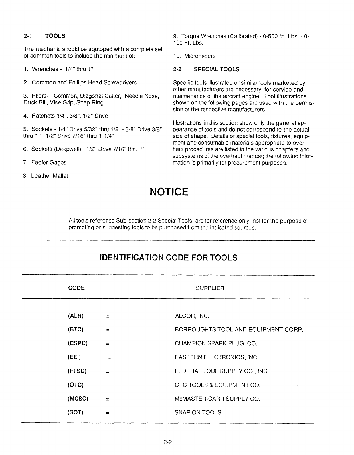
The mechanic should be equipped with
of common tools to include the minimum of:
1.
TOOLS
Wrenches - 114" thru
1
a
complete set
"
9.
Torque Wrenches (Calibrated) - 0-500 In. Lbs. - 0-
100
Ft.
Lbs.
10.
Micrometers
2-2
SPECIAL TOOLS
2. Common and Phillips Head Screwdrivers
-
3. PliersDuck Bill, Vise Grip, Snap Ring.
4. Ratchets
5.
Sockets - 114" Drive 5/32" thru 112" - 318" Drive 318"
thru 1"
6.
Sockets (Deepwell) - 112" Drive 7/16" thru 1"
7.
Feeler Gages
8. Leather Mallet
Common, Diagonal Cutter, Needle Nose,
1/4", 318", 1/22'' Drive
-
112" Drive 7/16" thru 1-114"
All tools reference Sub-section
promoting or suggesting tools to be purchased from the indicated sources.
Specific tools illustrated or similar tools marketed by
other manufacturers are necessary for service and
maintenance of the aircraft engine. Tool illustrations
shown on the following pages are used with the permis-
sion of the respective manufacturers.
lllustrations in this section show only the general ap-
pearance of tools and do not correspond to the actual
size of shape. Details of special tools, fixtures, equipment and consumable materials appropriate to overhaul procedures are listed in
subsystems of the overhaul manual; the following information is primarily for procurement purposes.
the various chapters and
NOTICE
2-2
Special Tools, are for reference only, not for the purpose of
IDENTIFICATION
CODE SUPPLIER
(ALR)
(BTC)
(CSPC)
(FTSC)
(OTC)
(MCSC)
(SOT)
CODE
FOR TOOLS
ALCOR, INC.
BORROUGHTS TOOL AND EQUIPMENT CORP.
CHAMPION SPARK PLUG, CO.
EASTERN ELECTRONICS, INC.
FEDERAL TOOL SUPPLY CO., INC.
OTC TOOLS
McMASTER-CARR SUPPLY CO.
SNAP ON TOOLS
&
EQUIPMENT CO.
SPECIAL
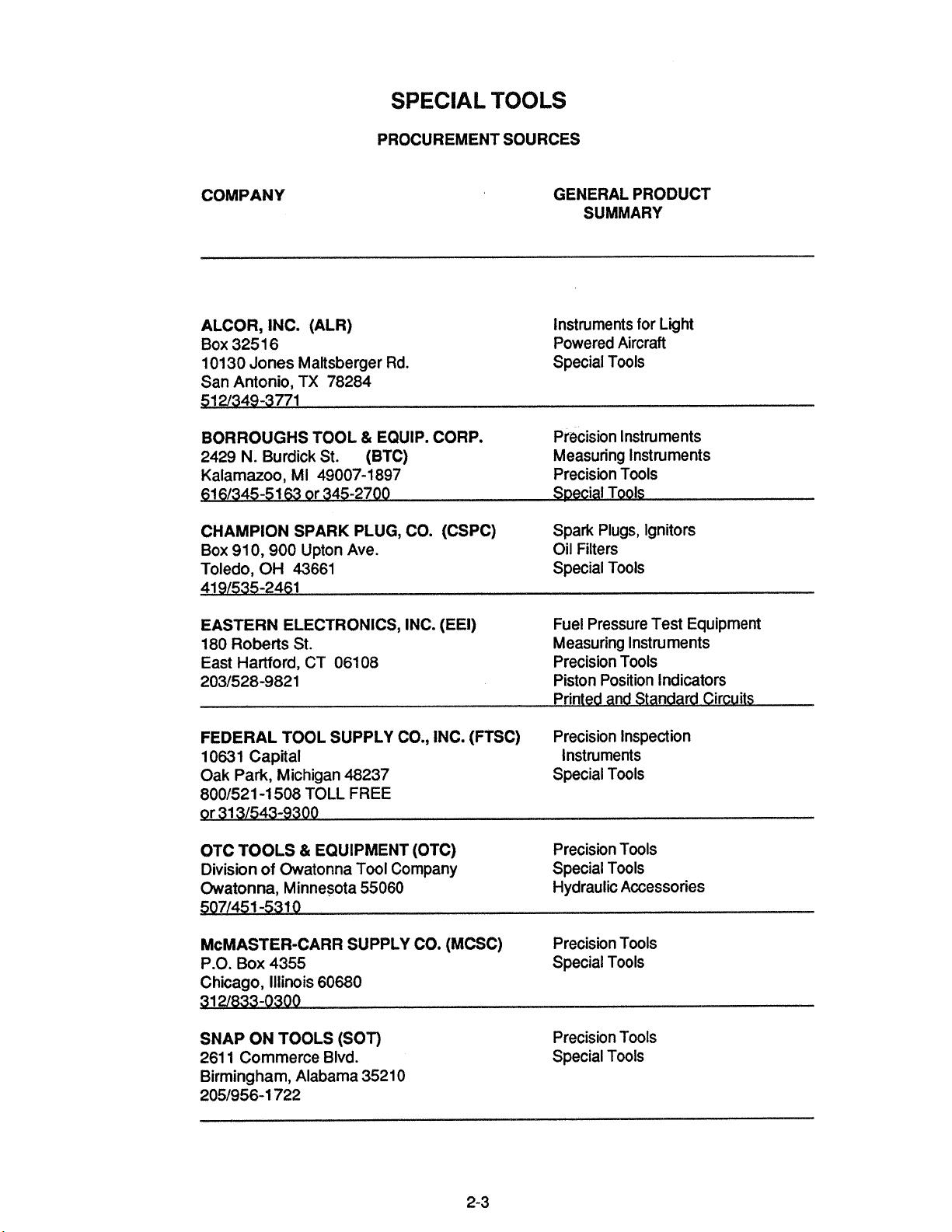
PROCUREMENT SOURCES
TOOLS
COMPANY
ALCOR, INC. (ALR)
Box 325 1 6
10130 Jones
San Antonio, TX 78284
BORROUGHS TOOL & EQUIP. CORP.
N.
2429
Kalamazoo, MI 49007-1 897
51 61345-51
CHAMPION SPARK PLUG, CO. (CSPC)
Box 91 0,900
Toledo, OH 43661 Special Tools
41 91535-2461
EASTERN ELECTRONICS, INC. (EEI)
180 Roberts St. Measuring Instruments
East Hartford, CT 06108
2031528-9821 Piston Position Indicators
Maltsberger Rd.
Burdick St.
63
or 345-2700
Upton Ave.
(BTC)
GENERAL PRODUCT
SUMMARY
Instruments for
Powered Aircraft
Special Tools
Precision Instruments
Measuring Instruments
Precision Tools
S~ecial Tools
Spark Plugs, Ignitors
Oil Filters
Fuel Pressure Test Equipment
Precision Tools
Printed and Standard Circuits
Light
FEDERAL TOOL SUPPLY CO., INC. (FTSC)
10631 Capital Instruments
Oak Park, Michigan 48237
8001521 -1 508 TOLL
9r 31 31543-9300
OTC TOOLS & EQUIPMENT (OTC)
Division of Owatonna Tool Company
Owatonna, Minnesota 55060 Hydraulic Accessories
5071451 -531 0
McMASTER-CARR SUPPLY CO. (MCSC)
P.O. Box 4355 Special Tools
Chicago, Illinois 60680
SNAP ON TOOLS (SOT)
261 1 Commerce Blvd.
Birmingham, Alabama 3521 0
2051956-1 722
FREE
Precision Inspection
Special Tools
Precision Tools
Special Tools
Precision Tools
Precision Tools
Special Tools
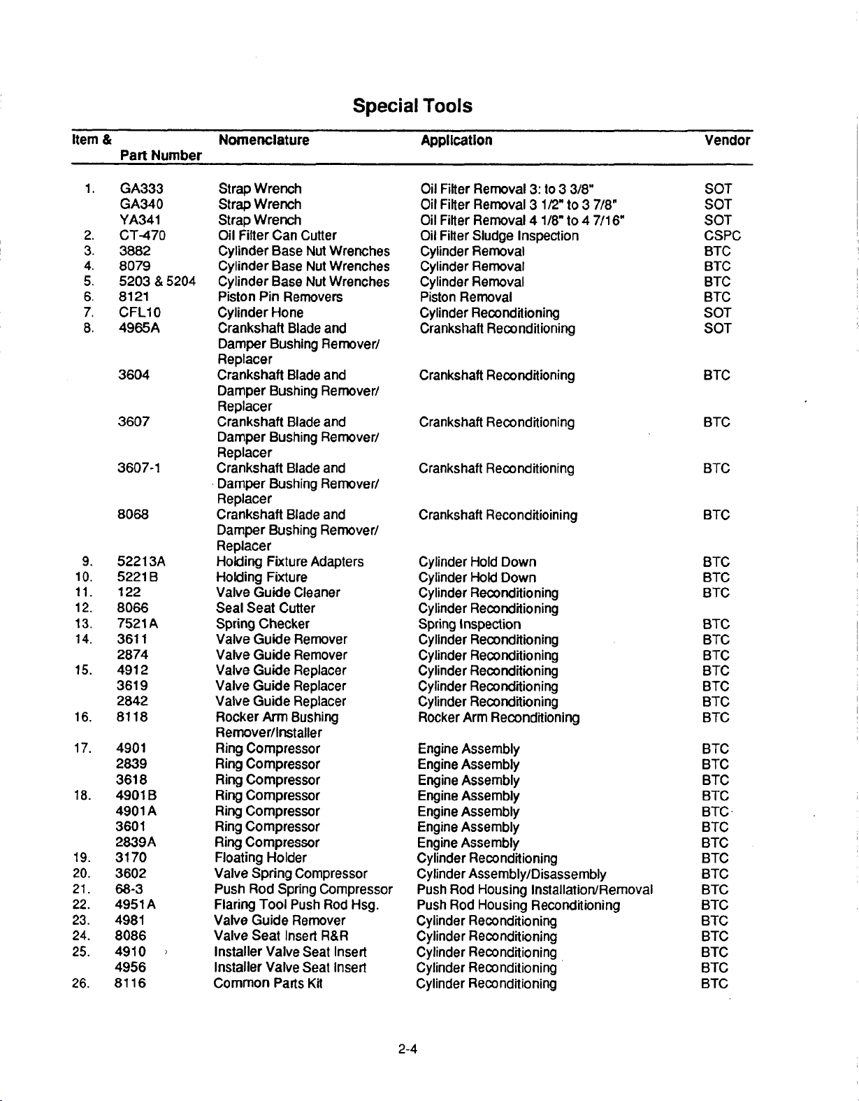
Item
1.
2.
3.
4.
5.
6.
7.
8.
9.
10.
11.
12.
13.
14.
15.
16.
17.
18.
19.
20.
21.
22.
23.
24.
25.
26.
&
Part
GA333
GA340
YA341
CT-470
3882
8079
5203
8121
CFLIO0
4965A
3604
3607
3607-1
8068
52213A
5221
122
80866
7521
3611
2874
4912
3619
2842
8118
4901
2839
3618
4901
4901
3601
2839A
3170
3602
68-3
4951
4981
8086
4910
4956
8116
Number
&
5204
B
A
B
A
A
Nomenclature
Strap
Wrench
Strap
Wrench
Strap
Wrench
Oil
Filter
Can
Cutter
Cylinder
Cylinder
Cylinder
Piston
Cylinder
Crankshaft
Damper
Base
Base
Base
Pin
Removers
Hone
Blade
Bushing
Nut
Nut
Nut
Replacer
Crankshaft
Damper
Blade and
Bushing Remover/
Replacer
Crankshaft
Damper
Blade
Bushing
Replacer
Crankshaft
Damper
Blade
Bushing
Replacer
Crankshaft
Damper
Blade
Bushing
Replacer
Holding
Holding
Valve
Seal
Spring
Valve
Valve
Valve
Valve
Valve
Rocker
Fixture
Fixture
Guide
Seat
Cutter
Checker
Guide
Guide
Guide
Guide
Guide
Arm
Adapters
Cleaner
Remover
Remover
Replacer
Replacer
Replacer
Bushing
Remover/Installer
Ring
Compressor
Ring
Compressor
Ring
Compressor
Ring
Compressor
Ring
Compressor
Ring
Compressor
Ring
Compressor
Floating
Valve
Push
Flaring
Valve
Valve Seat
Installer
Installer
Common
Holder
Spring
Rod
Spring
Tool
Guide
Insert
Valve
Valve
Parts
Compressor
Compressor
Push Rod
Remover
Seat
Seat
Kit
Special
Wrenches
Wrenches
Wrenches
and
Remover/
and
Remover/
and
Remover/
and
Remover/
Hsg.
R&R
Insert
Insert
Tools
Application
Oil
Filter
Removal
Oil
Filter
Removal
Oil
Filter
Removal 4 1/8"
Oil
Filter
Sludge
Cylinder
Cylinder
Cylinder
Piston
Cylinder
Crankshaft
Crankshaft
Crankshaft
Crankshaft
Crankshaft
Cylinder
Cylinder
Cylinder
Cylinder
Spring
Cylinder
Cylinder
Cylinder
Cylinder
Cylinder
Rocker
Engine
Engine
Engine
Engine
Engine
Engine
Engine
Cylinder
Removal
Removal
Removal
Removal
Reconditioning
Reconditioning
Reconditioning
Reconditioning
Reconditioning
Reconditioining
Hold
Hold
Reconditioning
Reconditioning
Inspection
Reconditioning
Reconditioning
Reconditioning
Reconditioning
Reconditioning
Arm
Assembly
Assembly
Assembly
Assembly
Assembly
Assembly
Assembly
Reconditioning
Cylinder Assembly/Disassembly
Push
Rod
Housing
Push
Rod
Housing
Cylinder
Cylinder
Cylinder
Cylinder
Cylinder
Reconditioning
Reconditioning
Reconditioning
Reconditioning
Reconditioning
3:
to 3 3/8"
3
1/2"
to 3 7/8"
to 4 7/16"
Inspection
Down
Down
Reconditioning
Installation/Removal
Reconditioning
Vendor
SOT
SOT
SOT
CSPC
BTC
BTC
BTC
BTC
SOT
SOT
BTC
BTC
BTC
BTC
BTC
BTC
BTC
BTC
BTC,
BTC
BTC
BTC
BTC
BTC
BTC
BTC
BTC
BTC
BTCBTC
BTC
BTC
BTC
BTC
BTC
BTC
BTC
BTC
BTC
BTC
2-4
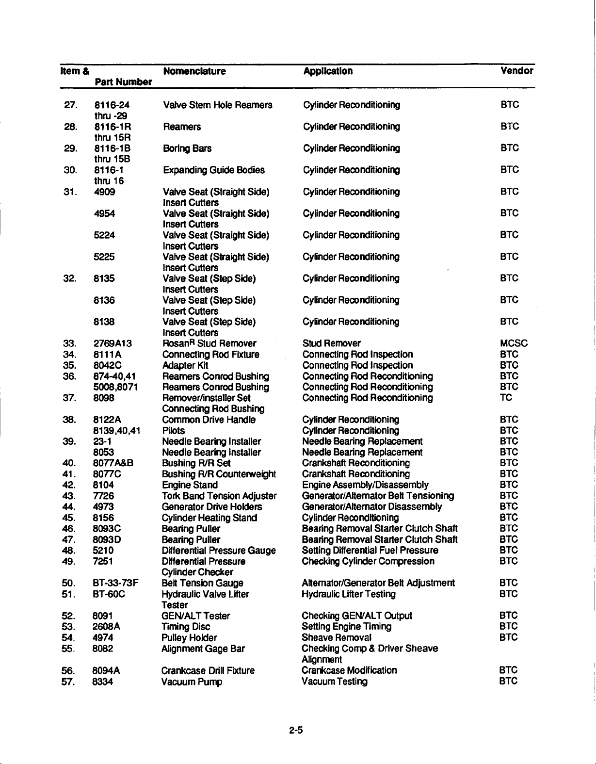
item
&
Part
Number
Nomenclature Application
Vendor
27.
28.
29.
30.
31.
32.
33.
34.
35.
36.
37.
38.
39.
40.
.41.
42.
43.
44.
45.
46.
47.
48.
49.
50.
51.
52.
53.
54.
55.
56.
57.
8116-24
thru
-29
8116-1iR
thru
15R
8116-l
B
thru
15B
8116-1
thru 1 6
4909 Valve
4954 Valve
5224
5225
8135
8136
8138
2769A1
8111
8042C Adapter
874-40,41
5008,8071
8098 Remover/installer
8122A
8139,40,41
23-1
8053 Needle
8077A&B
8077C
8104
7726
4973 Generator
8156
8093C
8093D
5210
7251
BT-33-73F
BT-60C
8091
2608A
4974
8082
8094A
8334
3
A
Valve
Stem
Hole
Reamiers
Reamers
Boring
Expanding
insert Cutters
Insert
Valve
Insert
Valve
Insert
Valve Seat (Step
Insert
Valve
Insert
Valve Seat
Insert
RosanR
Connecting
Reamers
Reamers
Connecting
Common
Pilots
Needle Bearing
Bushing
Bushing
Engine
Tork Band
Cylinder Heating
Bearing
Bearing
Differential
Differential Pressure
Cylinder Checker
Belt
Hydraulic
Tester
GEN/ALT Tester
Timing Disc
Pulley Holder
Alignment
Crankcase
Vacuum
Bars
Guide
Bodies
Seat
(Straight Side)
Seat (Straight Side)
Cutters
Seat
(Straight
Cutters
Seat
(Straight
Cutters
Side)
Cutters
Seat
(Step
Side)
Cutters
(Step
Side)
Cutters
Stud
Remover
Rod
Fixture
Kit
Conrod
Conrod
Drive
Bearing
R/R
R/R Counterweight
Stand
Tension
Drive
Puller
Puller
Tension
Valve
Gage
Pump
Bushing
Bushing
Set
Rod
Bushing
Handle
Installer
Installer
Set
Adjuster
Holders
Stand
Pressure
Gauge
Lifter
Bar
Drill
Fixture
Side)
Side)
Gauge
Cylinder
Cylinder
Cylinder
Cylinder
Cylinder
Cylinder Reconditioning
Cyiinder Reconditioning
Cylinder Reconditioning
Cylinder Reconditioning
Cylinder Reconditioning
Cylinder
Stud
Connecting
Connecting
Connecting
Connecting
Connecting
Cylinder
Cylinder
Needle
Needle
Crankshaft
Crankshaft
Engine
Generator/Altemator
Genierator/Alternator
Cylinder Reconditioning
Bearing Removal
Bearing Removal
Setting
Checking
Alternator/Generator
Hydraulic
Checking
Setting
Sheave
Checking
Alignment
Crankcase
Vacuum
Reconditioning
Reconditioning
Reconditioning
Reconditioning
Reconditioning
Reconditioning
Remover
Rod
Inspection
Rod
Inspection
Rod
Reconditioning
Rod
Reconditioning
Rod
Reconditioning
Reconditioning
Reconditioning
Beaning
Bearing
Assembly/Disassembly
Differential
Engine
Removal
Testing
Replacement
Replacement
Reconditioning
Reconditioning
Belt
Disassembly
Starter
Starter
Cylinder
Lifter
Testing
GEN/ALT
Timing
Camp & Driver
Modification
Clutch
Clutch
Fuel
Pressure
Compression
Belt
Output
Sheave
Tensioning
Adjustment
Shaft
Shaft
BTC
BTC
BTC
BTC
BTC
BTC
BTC
BTC
BTC
BTC
BTC
MCSC,
BTC
BTC
BTC
BTC
TC
BTC
BTC
BTC
BTC
BTC
BTC
BTC
BTC
BTC
BTC
BTC
BTC
BTC
BTC
BTC
BTC
BTC
BTC
BTC
BTC
BTC
2-5
Item
&
Part
Number
Nomenclature
Application
Vendor
58.
59.
60.
61.
62.
63.
64.
65.
66.
67.
68.
69.
70.
71.
72.
73.
74.
75.
76.
77.
78.
79.
80.
81.
82.
83.
84.
85.
86.
87.
88.
89.
61-5
8094B
4918
8084
8065
504-1
4919
8054
445
8074
505
4978
8025
L423
5209
8048
8155
8117A
8087A&B
8165
8114
7912A
7710
1153
679
1035
927
1037
1079
1063
115-153
545-116
122-125
126-137
226-137
159-211
4903-1
thru
-5
4905
5129-1
thru
-5
5130
7232
4914-1H-S
thru 5HS
4943-1HS
thru 5HS
Pulley
Puller
Drill
Fixture
Spark
Plug
Insert
Replacer
Step
Cutter
Thru-Bolt
Step
Cutter
Thru-Bolt
Spark
Plug
Insert Tap
Spark
Plug
Insert
Remover
Slide
Hammer
Spark
Plug
Tap
RosanR
Stud
Scavenge
Drill
Crankcase Spitter
Propeller
Installer
Oil
Facer
Oil
Facer
Runout
Poilshing Tools
Crankshaft
Injector
and
Crankcase
Hex
Rotabroach
Puller
Puler
Puiler
Puller
Puller
Puller
Puller
Outside Micrometers
Dial
Blade
Screw
Screw
Depth
Reamers
Support
Reamers
Shaft
Reamers
Cylinder)
Reamer
Bushing
Reamer
Bushing
Reamers
Reamers
Lock Ring
Drivers
Pump
Fixture
Shaft
Oil
Pressure
Pressure
Installer
Drive
Bore
Bushing
Relief
Relief
Block
Set
Bearings
Nozzle Remover
thru
Cutters
Gages
Micrometers
Thread
Thread
Micrometers
Micrometers
Micrometers
Rocker
Boss
Rocker
(Straight
Rocker
Rocker
Valve
Guide
Valve
Guide
Installer
Drill
Seal
Spot
Spot
for
Bolt
Removers
Shaft
Arm
VIve
Shaft
Arm
Fixture
&
Boss
Boss
GEN/ALT
Journal
Cylinder
Crankcase
Crankcase
Cylinder
Cylinder
Multi
Cylinder
Stud
Stud
Crankcase
Crankcase
Crankcase
Installation
Removal
holes
Removal
holes
Crankshaft
Crankshaft
Injector
Engine
Loosening
Hole
Removal
Removal
Removal
Removal
Removal
Removal
Removal
Dimensional Inspection
Dimensional Inspection
Dimensional
Dimensional
Dimensional
Dimensional Inspection
Cylinder
Rocker
Cylinder
Cylinder
Rocker
Cylinder
Cylinder
Sheave Removal
Bearing
Reconditioning
Reconditioning
Reconditioning
Use
Reconditioning
Installation
Installation
of
of
Removal & Replacement
Disassembly
Cutting
of
of
of
of
of
of
of Press
Reconditioning
Arm
Reconditioning
Reconditioning
Arm
Reconditioning
Reconditioning
Modification
Modification
Modification
Modification
Squirt
Nozzle
Separation
of Seal
Inspection
Reconditioning
Tubing
over Propf
surface
surface
Press
Press
Press
Press
Press
Press
Inspection
Inspection
Inspection
Reconditioning
Reconditioni
Material
Material
"B*
Nuts
Fit
Parts
Fit
Parts
Fit
Parts
Fit
Parts
Fit
Parts
Fit
Parts
Fit
Parts
Replacement
lange
around
around
ng
BTC
BTC
BTC
BTC
BTC
BTC
BTC
BTC
BTC
BTC
BTC
BTC
BTC
BTC
BTC
BTC
BTC
BTC
BTC
BTC
BTC
BTC
BTC
OTC
OTC
OTC
OTC
OTC
OTC
OTC
FTSC
FTSC
FTSC
FTSC,
FTSC
FTSC
BTC
BTC
BTC
BTC
BTC
BTC
BTC
2-6
Item
&
Part
Number
Nomenclature
Application
Vendor
90. 2847-2Cp
4913-1
3606-CP
2847-1
2847-2HP
4913-1HP
3606-HP
28471
HP
91.
92.
93.
94.
95.
96.
97.
98.
99.
100.
101.
102.
103.
104.
105.
2684
2686
2689
2693
4104
2848-1
2848-2
3615
7308
52.030-006
600R-30
647
E100
Model
29
11-9110-1
Model
E25
Model
El
Model
E5
646953
85328
85329
Cp
Cp
0
Reamer
Reamer (Carbide
Reamer (Carbide
Reamer
Reamer
Reamer
Reamer
Reamer
Reamer
Reamer
Reamer (Square
Reamer
Reamer
Plug
Plug
Plug Gage
Dial
Precision
Inside Measuring
Alternator Analyzer
Regulator
Aftemnator/Regulator/
Battery
Voltage
Magneto
Timing
Cold
Hi-Voltage
Master
Alcor
Unit
Alcor
Unit
(Carbide
(Carbide
(High
(High
(High
(High
(Square
(Square
(Square
(Square
Gage
Gage
Thickness
Vernier
Tester
Tester
&
Circuit
Timing
Indicator
Cylinder Tester
Tester
Orifice Tool
Portable
Portable
Tipped)
Tipped)
Tipped)
Tipped)
Speed
Speed
Speed
Speed
Shank)
Shank)
Shank)
Shank)
Shank)
Gage
Calipers
Instrument
Tester
Light
Digital
Digital
Steel)
Steel)
Steel)
Steel)
Voltage
EGT
CHT
Cylinder
Cylinder Reconditioning
Cylinder
Cylinder
Cylinder
Cylinder
Cylinder
Cylinder
Cylinder
Cylinder
Cylinder
Cylinder
Cylinder Reconditioning
Valve
Valve
Valve
Dimensional
Dimensional
Dimensional
Charging
Charging
Electrical
Set
Set
Cylinder
Test
Cylinder
Engine
Engine Test
Reconditioning
Reconditioning
Reconditioning
Reconditioning
Reconditioning
Reconditioning
Reconditioning
Reconditioning
Reconditioning
Reconditioning
Reconditioning
Guide
Inspection
Guide
Inspection
Guide
Inspection
Inspection
Inspection
Inspection
System
System
System Test
Engine
Engine
Timing
Timing
Firing
Improperly
Ignition
Cable
Compression
Test
Test
Test
Continuity
Test
BTC
BTC
BTC
BTC
BTC
BTC
BTC
BTC
BTC
BTC
BTC
BTC
BTC
BTC
BTC
BTC
FTSC
FTSC
FTSC
EEl
EEl
EEl
KTC
EEl
EEI
KTC
BTC
ALR
ALR
2-7
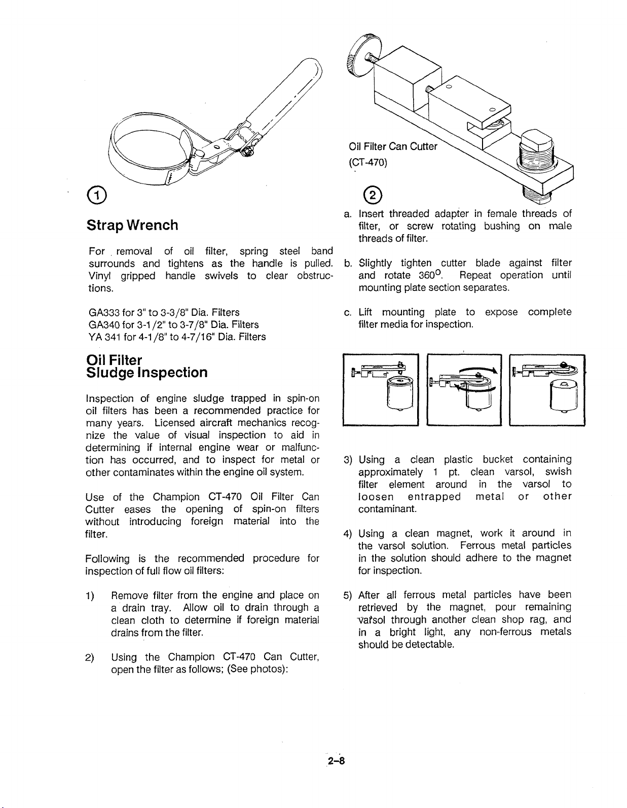
a. Insert threaded adapter in female threads of
Strap
For removal of oil filter, spring steel band
surrounds and tightens as the handle is pulled. b. Slightly tighten cutter blade against filter
Vinyl gripped handle swivels to clear obstruc- and rotate
tions. mounting plate section separates.
GA333 for 3" to 3-3/8" Dia. Filters c. Lift mounting plate to expose complete
GA340 for 3-1
YA 341 for 4-1
Oil
Sludge
lnspection of engine sludge trapped in spin-on
oil filters has been a recommended practice for
many years. Licensed aircraft mechanics recog-
nize the value of visual inspection to aid in
determining if internal engine wear or malfunction has occurred, and to inspect for metal or
other contaminates within the engine oil system.
Use of the Champion CT-470 Oil Filter Can
Cutter eases the opening of spin-on filters
without introducing foreign material into the
filter.
Following is the recommended procedure for
inspection of full flow oil filters:
Wrench
Filter
Inspection
/2"
to 3-7/8" Dia. Filters
/8"
to 4-7/16" Dia. Filters
filter, or screw rotating bushing on male
threads of filter.
360'. Repeat operation until
filter media for inspection.
3) Using a clean plastic bucket containing
1
approximately
filter element around in the varsol to
loosen entrapped metal or other
contaminant.
4)
Using a clean magnet, work it around in
the varsol solution.
in the solution should adhere to the magnet
for inspection.
pt. clean varsol, swish
Ferrous metal particles
Remove filter from the engine and place on
1)
a drain tray. Allow oil to drain through a
clean cloth to determine if foreign material
drains from the filter.
2)
Using the Champion CP-470 Can Cutter,
open the filter as follows; (See photos):
5)
After all ferrous metal particles have been
retrieved by the magnet, pour remaining
vatsol through another clean shop rag, and
in a bright light, any non-ferrous metals
should be detectable.
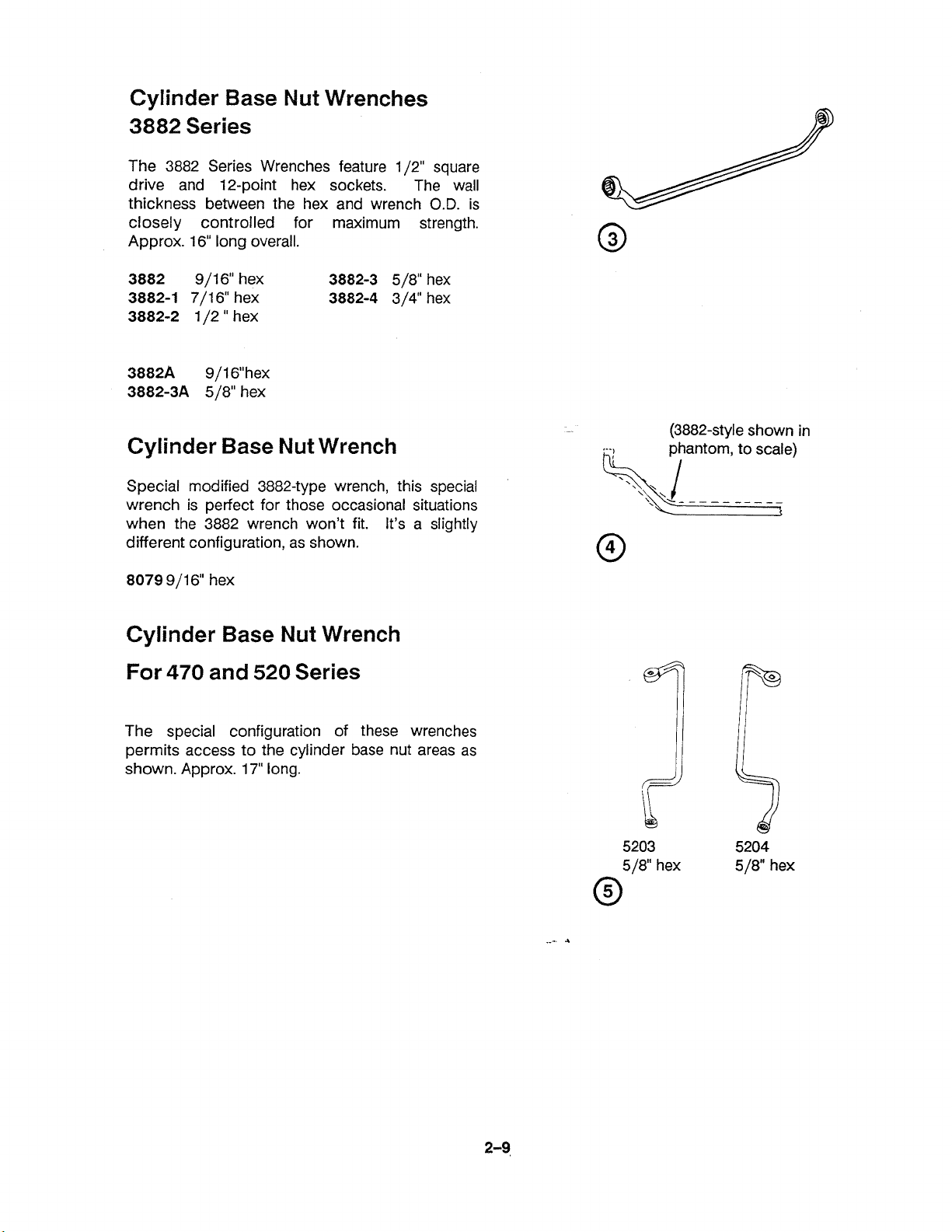
Cylinder Base
Nut
Wrenches
3882 Series
The 3882 Series Wrenches feature 1/2" square
drive and 12-point hex sockets. The wall
thickness between the hex and wrench
closely controlled for maximum strength.
Approx. 16" long overall.
O.D.
is
3882
3882-1
3882-2
3882A
3882-3A
Cylinder Base
Special modified 3882-type wrench, this special
wrench is perfect for those occasional situations
when
different configuration, as shown.
8079
Cylinder Base
9/16" hex
7/16" hex
1 /2 " hex
9/16"hex
5/8" hex
Nut
the 3882 wrench won't fit. It's a slightly
9/16" hex
Nut
3882-3
3882-4
Wrench
Wrench
5/8" hex
3/4" hex
For 470 and 520 Series
(3882-style shown in
The special configuration of these wrenches
permits access to the cylinder base nut areas as
shown. Approx. 17" long.
5203 5204
5
18" hex
5
18" hex
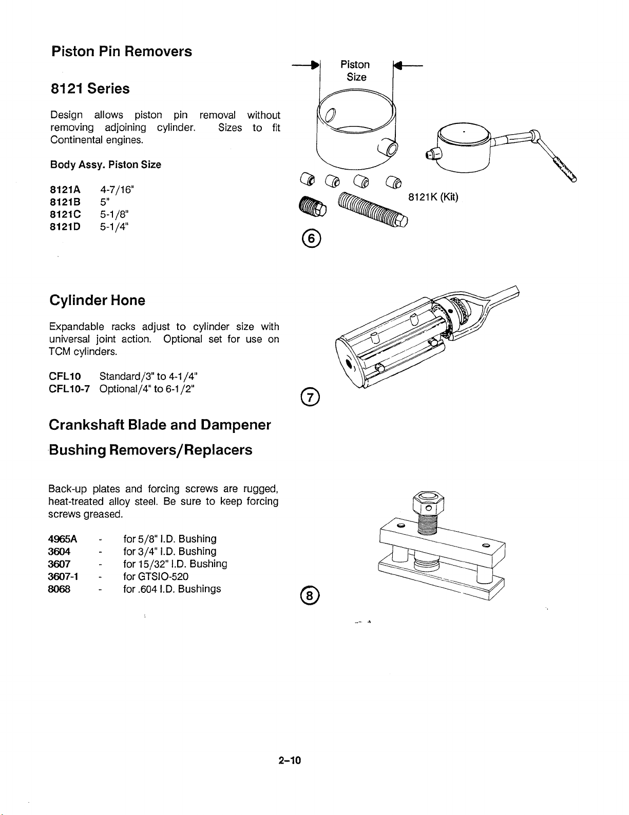
Piston Pin Removers
8121
Design allows piston pin removal without
removing adjoining cylinder. Sizes to fit
Continental engines.
Body Assy.
Series
Piston
Size!
Cylinder Hone
Expandable racks adjust to cylinder size with
universal joint action. Optional set for use on
TCM cylinders.
81
21
K (Kit)
Crankshaft Blade and Dampener
Back-up plates and forcing screws are rugged,
heat-treated alloy steel. Be sure to keep forcing
screws greased.
4965A
3604
3607
3607-1
8068
-
for 518" I.D. Bushing
-
for 314" I.D. Bushing
-
for 15/32" I.D. Bushing
-
for GTSIO-520
-
for
,604
I.D. Bushings
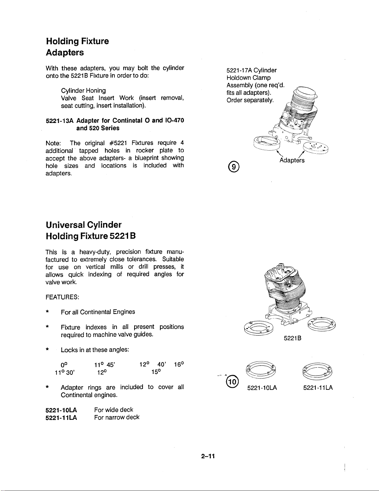
Holding Fixture
Adapters
With these adapters, you may bolt the cylinder
onto the 5221
Cylinder Honing
Valve Seat Insert Work (insert removal,
seat cutting, insert installation).
5221-13A Adapter for Continetal 0 and 10-470
Note: The original #5221 Fixtures require
additional tapped holes in rocker plate to
accept the above adapters- a blueprint showing
hole sizes and locations is included with
adapters.
B
Fixture in order to do:
and 520 Series
4
Universal Cylinder
Holding Fixture
5221
B
-1
7A
5221
t-loldown Clamp
Assembly (one req'd.
fits all adapters).
Order separately.
Cylinder
This is a heavy-duty, precision fixture manufactured to extremely close tolerances. Suitable
for use on vertical mills or drill presses, it
allows quick indexing of required angles for
valve work.
FEATURES:
*
For all Continental Engines
*
Fixture indexes in all present positions
required to machine valve guides.
*
Locks in at these angles:
*
Adapter rings are included to cover all
Continental engines.
5221-10LA
5221-1 1LA
For wide deck
For narrow deck
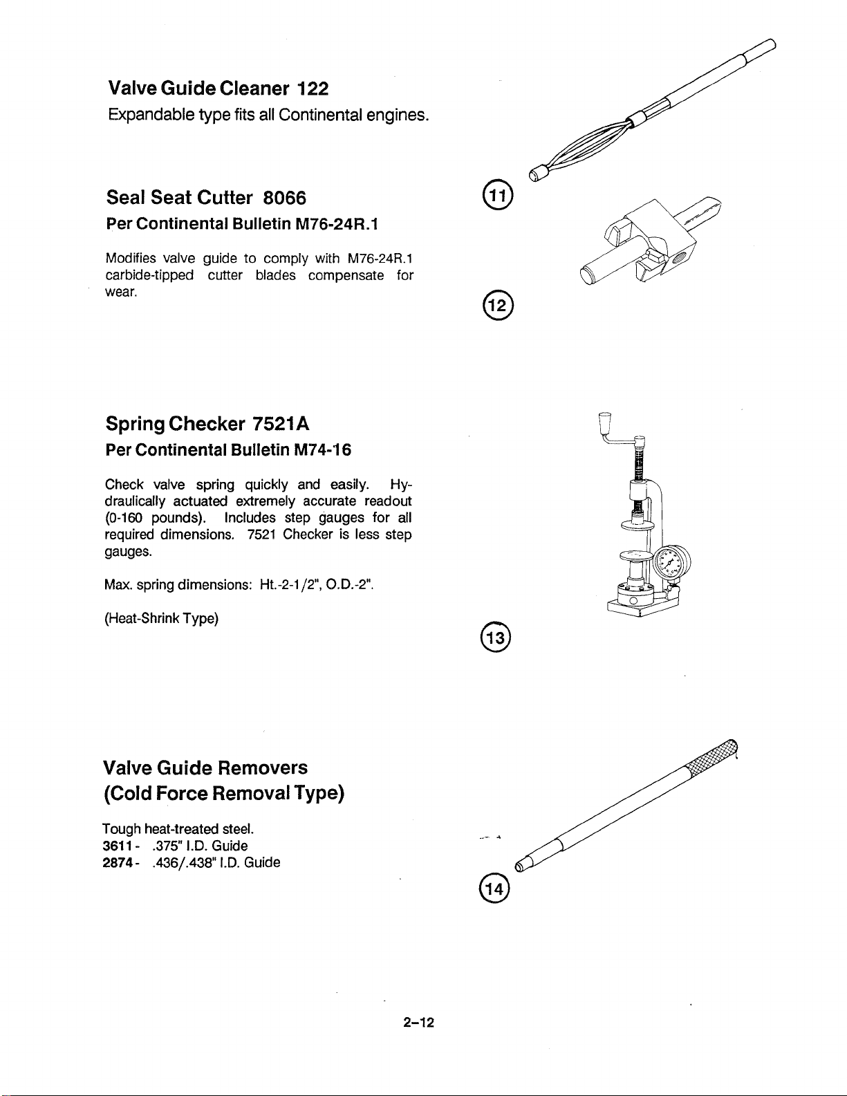
Valve Guide Cleaner 122
Expandable type fits all Continental engines.
Seal Seat Cutter
Per Continental Bulletin
Modifies valve guide to comply with
carbide-tipped cutter blades compensate for
wear.
Spring Checker 7521
Per Continental Bulletin
Check valve spring quickly and easily. Hy-
draulically actuated extremely accurate readout
(0-160
required dimensions. 7521 Checker is less step
gauges.
Max.
pounds). Includes step gauges for all
spring dimensions: Ht.-2-1/2", 0.D.-2".
8066
M76-24R.1
M76-24R.1
A
M74-16
(Heat-Shrink Type)
Valve Guide Removers
(Cold Force Removal 'Type)
Tough heat-treated steel.
361
1
-
.375"
I.D. Guide
2874 - .436/.438"
1.D.
Guide
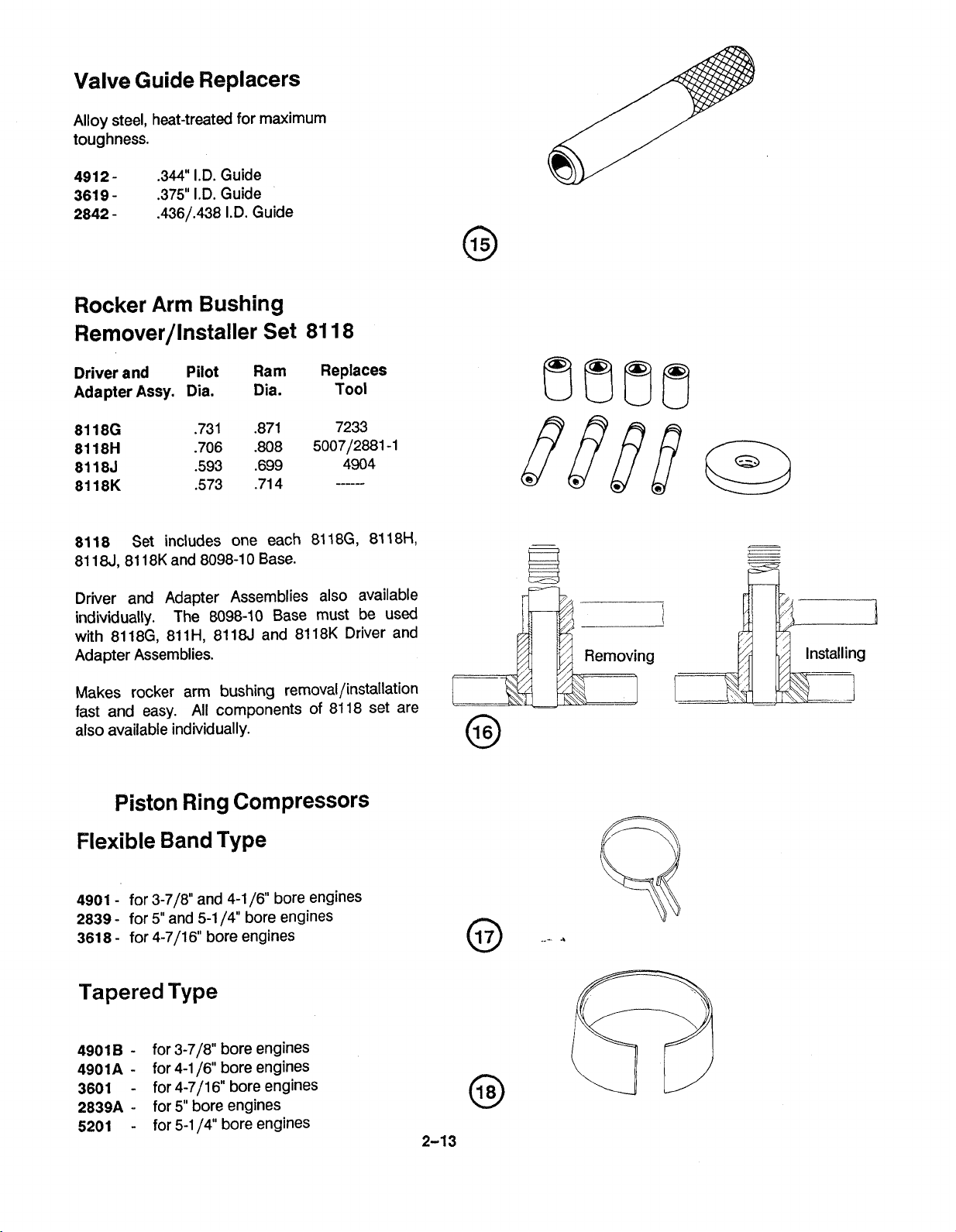
Valve Guide Replacers
Alloy steel, heat-treated for maximum
toughness.
4912361 9
2842
.344" I.D. Guide
-
.375" 1.D. Guide
-
.436/.438 I.D. Guide
Rocker Arm Bushing
Remover/lnstaller Set 81 18
Driver and
Adapter
8118
81 184 81 18K and 8098-1 0 Base.
Driver and Adapter Assemblies also available
individually. The 8098-10 Base must be used
with
Adapter Assemblies.
Assy.
Set includes one each 81 18G, 81 18H,
81 18G, 81 1H, 8118J and 81 18K Driver and
Pilot
Dia.
Ram Replaces
Dia. Tool
Makes rocker arm bushing
fast and easy. All components of 81 18 set are
also available individually.
removal/installation
Piston Ring Compressors
Flexible Band
4901
-
for 3-718" and 4-1 16" bore engines
2839
-
for
5"
and 5-1 14" bore engines
361 8
-
for 4-7/16 bore engines
Type
Tapered Type
4901
B
-
for 3-718" bore engines
4901A
3601
2839A
5201
-
for 4-1 16" bore engines
-
for 4-711 6" bore engines
-
for 5" bore engines
-
for 5-1 14" bore engines

31 70 - Floating holder
No. 3 Morse male, compensates for misalignment
between reamer and work. Provides
unrestricted float.
Valve Spring
Compressor 3602
Adjustable type works on all Continental
engines.
Hook installs on rocker shaft (or on special
rocker nut furnished) and c-shaped collar
compresses spring to allow keeper removal.
stressed parts are heated-treated steel. Handle
18"
is approx.
long for good leverage.
All
Push Rod Spring
Compressor 68-3
For compressing and holding push rod springs
on all engines with spring loaded tubes. The
68-3
compresses the spring, which can then be
removed with furnished clips.
Eliminates wiring springs together- to install,
simply insert spring then pull off clip!
instructions.
Includes
Flaring Tool for Push
Rod Housing 4951
For A
Balls rotate inside housing, expanding it into
aluminum boss.
81
C Series - expanding ball type tool.
A
Valve Guide Remover 4981
Removes guides by heat-shrink method.
Cylinder is heated to
water to guide bore.
hammer removes guide.
included) supplies the low water pressure
required to cool the guides for easy removal.
Replacement guide is usually same size as the
one removed.
475O~, then tool injects
A
light tap with the
A
water reservoir (not
slide
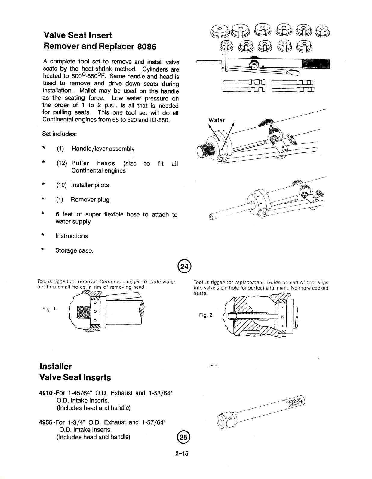
Valve Seat Insert
Remover and Replacer
A
complete tool set to remove and install valve
8086
seats by the heat-shrink method. Cylinders are
heated to
500~-550°F. Same handle and head is
used to remove and drive down seats during
installation. Mallet may be used on the handle
as the seating force. Low water pressure on
the order of
1
to 2 p.s.i. is all that is needed
for pulling seats. This one tool set will do all
Continental engines from 65 to 520 and 10-550.
Set includes:
*
(1) Handle/lever assembly
*
(12) Puller heads (size to fit all
Continental engines
*
(1
0)
Installer pilots
*
(1)
Remover plug
*
6 feet of super flexible hose to attach to
water supply
*
Instructions
*
Storage case.
Tool is rigged for removal. Center
out thru small holes in rim of
Fig.
1.
is
plugged to
removina head.
"
route water
Installer
Valve Seat lnserts
491 0 -For 1-45/64" O.D. Exhaust and 1-53/64"
O.D. Intake lnserts.
(Includes head and handle)
Tool
is
rigged for replacement. Guide on end of tool slips
into valve stem hole for
seats
Flg
2
perfect alianment.
No
more cocked
4956-For
1-3/4" O.D. Exhaust and 1-57/64
O.D. lntake Inserts.
(Includes head and handle)
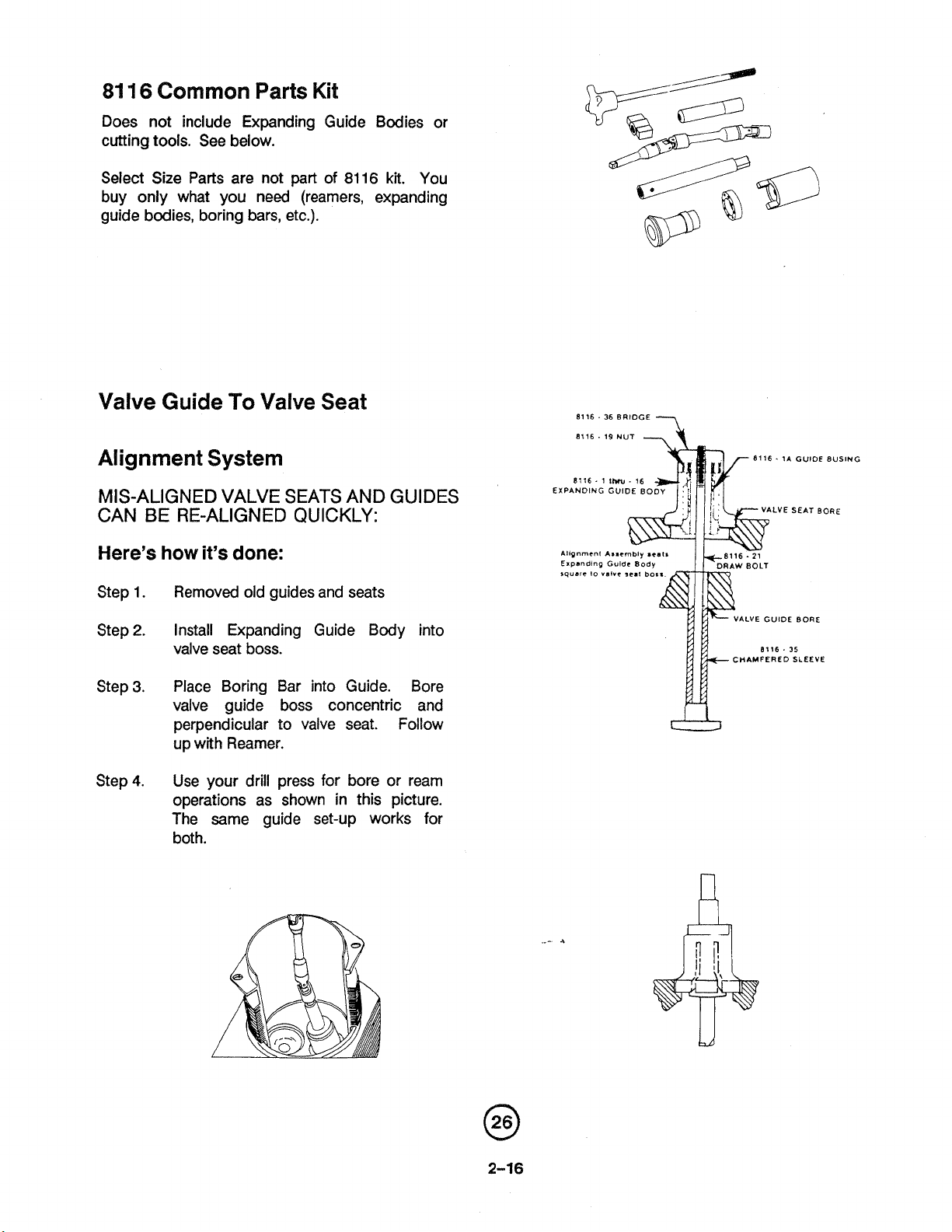
81
16
Common
Parts Kit
Does not include Expanding Guide Bodies or
cutting tools. See below.
part
of
81
16
kit.
Select Size Parts are not
You
buy only what you need (reamers, expanding
guide bodies, boring bars, etc.).
Valve Guide
To
Valve Seat
Alignment System
MIS-ALIGNED VALVE SEATS AND GUIDES
BE
CAN
Here's how it's done:
Step
Step
Step
Step
RE-ALIGNED QUICKLY:
Removed old guides and seats
1.
2.
Install Expanding Guide Body into
valve seat boss.
3.
Place Boring Bar into Guide. Bore
valve guide boss concentric and
perpendicular to valve seat. Follow
up with Reamer.
Use your drill press for bore or ream
4.
operations as shown in this picture.
The same guide set-up works for
both.
8116.
36
BRIDGE
8116 . 19 NUT
11116 - 1
EXPANDING GUIDE
1b.
16
80
---,
8116. 1A GUIDE BUSING
LVE SEAT BORE
GUIDE BORE
ALVE
CHAMFERED SLEEVE
 Loading...