

Teledyne Continental Motors GTSIO-520 Series, GTSIO-520-H, GTSIO-520-L, GTSIO-520-M, GTSIO-520-K Overhaul Manual
...
OVERHAUL
MANUAL
FOR
GTSIO-520
AIRCRAFT
SERIES
ENGINES
FORM
X-30045A
FAA
MARCH
APPROVED
1981
CURRENT
STATUS
OF
PAGES
AS
OF
PAGE
ithru
iv
V
vi
thru
viii
ix
thru
x
A-1-1
A-1
-2
A-2-1/A-2-2
A-3-1
A-3-2
A-3-3
thru
A-3-6
A-4-1
thru
A-4-13
A-4-14
A-4-15
A-4-18
A-4-19
A-4-21
A-4-26
A-4-27
A-4--30
A-5-1
A-6-1
A-6-2
A-7-1
A-8-1
A-9-1
A-9-4
A-10-1
A-10-2
A-10-3
A-10-5/A-10-6
A-11-1
A-1 1 -3
A-1 1 -4
A-1
A-12-2
A-12-4
A-12-5
A-1
A-13-1
A-13-3
A-1
A-13-5/A-13-6
A-14-1
2-1
2-7
3-4
thru
thru
thru
thru
thru
thru
thru
thru
thru
thru
thru
thru
thru
/A-1
thru
thru
A-5-4
A-7-6
A-8-2
A-9-3
A-9-6
2-8
INSERT
THE
MODELS
A-4-17
A-4-20
A-4-25
A-4-29
A-10-4
A-11-2
A-12-3
A-12-6
A-13-2
A-14-4
LATEST
PAGES
MARCH
PAGES
IN
THIS
PUBLICATION
GTSIO-520-C,
ISSUE
Original
June
1980
Original
March
1981
October
October
1980
March
1981
June
1980
Original
March 1981
Original
Original
March
1981
Original
1980
June
1980
Original
June
1980
Original
March
1981
Original
June
1980
Original
Original
Original
Original
June
1980
Original
June
1980
Original
June
1980
Original
June
1980
Original
March
1981
Original
June
1980
Original
March
1981
Original
March
1981
Original
June
1980
Original
1981
DESTROY
CONSIST
D,
PAGE
B-1
B-2
B-3
B-4
B-5
B-6
B-7
thru
B-1l
thru
B-14
thru
B-22
B-23
thru
B-26
B-27/B-28
C-1-1
thru
C-1
-8
C-1-9
thru
C-2-1
C-2-2
C-2-3
C-2-4
C-2-5
thru
C-2-7
thru
C-2-9
thru
C-2-13
C-3-1
thru
C-3-3
thru
C-3-5
thru
C-3-7
thru
C-3-9
thru
C-3-15
C-4-1
thru
C-4-3
C-4-4
thru
C-5-1
thru
C-5-3
thru
C-5-5
thru
C-5-9
C-5-10
C-5-13
C-6-1
thru
C-6-3
thru
C-6-5
thru
C-6-13
C-7-1
thru
H,
B-10
thru
thru
thru
thru
thru
OF
K,
B-13
B-21
B-25
C-1-7
C-1-16
C-2-6
C-2-8
C-2-12
C-2-16
C-3-2
C-3-4
C-3-6
C-3-8
C-3-14
C-3-18
C-4-2
C-4-20
C-5-2
C-5-4
C-5-8
C-5-12
C-5-16
C-6-2
C-6-4
C-6-1
C-6-16
C-7-18
SUPERSEDED
THE
FOLLOWING:
L,
M
and
2
PAGES
N
March
October
Original
March
Original
June
Original
June
Original
March
Original
October
Original
Original
June
Original
Original
June
Original
June
Original
June
Original
June
Original
June
Original
June
Original
June
Original
June
Original
Original
June
Original
March
Original
June
Original
June
Original
June
October
ISSUE
1981
1980
1981
1980
1980
1981
1980
1980
1980
1980
1980
1980
1980
1980
1980
1980
1980
1981
1980
1980
1980
1980
i-1.
COMPOSITION.
i-2.
This
adequate
operations
these
three
The
basic
a
hypothetical
the
most
involved.
basic)
and
covered
Chapter
Table
manual.
covered
cerned
indexed
model,
of
manual
Page
1
3
i-3.
i-4.
instructions
chapter
through
duction,
Illustrations,
Unpacking
Shipment,
Repair
assemblies.
Accessories
model
Chapter
GTSIO-520.
i-5.
i-6.
for
The
Chart
referred
of
only
Chapter
Limits.
A-
13
of
Chapter
Chapter
This
and
engine.
Chapter
This
all
engines
index
are
to
C.
by
are
Specification
publication
information
for
(3)
Chapters
engine
GTSIO-520
common
Any
differences
the
letter
by
the
Chapter
Limits
Personnel
this
with
by
the
A
All
pages,
numbered
-7
refers
A.
A.
chapter
for
the
consists
XIV.
These
Special
and
Preparation
Disassembly,
Replacement,
Final
and
Testing
Hereafter,
A
will
B.
chapter
covered
numbers
listed
as
reference
is
for
the
models
A,
overhaul
use
for
consolidated
letter
(the
of
Assembly,
be
consists
on
in
(Chapter
basic
between
model
of
Difference
B
is
the
all
engines
overhauling
the
Difference
of
basic),
figures
by
to
the
contains
basic
GTSIO
(14)
sections
Limits,
Tools
after
known
of
in
this
the
the
Table
numbers.
constructed
complete
covered
B,
and
C.
engine
the
seventh
for
Cleaning,
Limits
model,
items
engines
combined
covered
any
manual
his
particular
and
Chapter
and
following
complete
520
sections
cover
General
and
Service,
Assembly
Repair
Overhaul,
through
as
the
the
Table
consolidated
and
of
Limits
throughout
A)
is
written
of
all
Chapter
is
adequately
Data
listing
engine
will
Data
tables
page
of
overhaul
engine.
numbered
the
Description,
Equipment,
Storage
Inspection,
of
and
Testing
of
the
this
basic
of
manual.
Lubrication
and
FOREWORD
i-7.
Chapter
to
give
overhaul
covering
engines
A
(the
Section,
of
the
in
this
model
be
con-
Section,
engine
B
Table
in
this
system:
Section
This
Intro-
or
Sub-
of
basic
manual
model
Limits
are
to
I
i-8.
This
instructions
Table
ual
sections,
model.
for
the
coverage
Difference
those
i-9.
AVAILABILITY.
i-10.
Further
Contintal
be
purchased
Approved
craft
engine
such
publications
i-11.
SERVICE
i-12.
Important
changeability
datory
mation
and
duration
which
of
aircraft
study
to
aircraft
personnel
annual
service
i-13.
SERVICE
i-14.
It
Motors
and
requests
Distributors.
touch
them
maintenance
experience
maintenance
aircraft
at
most
C.
chapter
for
of
Contents.
each
Each
section,
basic
model
for
Data
for
the
same
copies
Motors
Distributors
parts.
of
replacements
are
among
covered
are
distributed
engines
at
their
offices.
owners,
may
subscription
covers
is
the
to
handle
for
These
with
operation
more
and
engines.
major
than
problems
work
airports.
contains
all
engine
This
chapter
relating
along
in
Chapter
overhaul.
Section
assemblies
of
aircraft
through
and
It
is
requested
be
placed
BULLETINS.
changes
parts,
and
the
subjects
by
to
and
parts
Service
operators
be
obtained
basis.
only
postage
REPORTS
policy
facilities
There
of
all
reports
information
facilities
and
willing
and
to
on
is
the
models
consists
to
a
with
A,
The
instructions
are
to
in
this
and
service
Teledyne
Parts
with
these
in
part
urgent
modernization
of
factory
all
Approved
and
Bulletins
and
by
direct
The
and
AND
Teledyne
of
through
are
repair.
to
help
well
perform
Teledyne
an
Approved
Difference
as
listed
of
particular
the
instructions
provide
be
the
publications
that
numbers,
inspection,
Service
are
charge
INQUIRIES.
service
complete
used
in
basic
other
Teledyne
Continental
Dealers
all
orders
facilities.
limited
Bulletins,
Distributors
available
of
maintenance
mail
for
handling.
Continental
difficulty
Approved
constantly
You
will
solve
equipped
any
necessary
Continental
Distributor
Data
in
the
individ-
engine
in
the
lieu
model
may
for
air-
for
inter-
man-
infor-
interest
for
interest
on
this
find
your
with
of
an
in
i
. . . . .A-6-1
. .. . .A-6-1
. .. .
. .. . .A-7-1
. .. . .A-7-1
. .. . .A-7-1
. .. .
. .. .
. .. .
. .. .
. .. .
. .. .
. .. .
......
......
......
......
......
......
......
......
.A-6-1
.A-7-1
.A-7-1
.A-7-1
.A-7-1
.A-7-2
.A-7-2
.A-7-2
A-7-2
A-7-2
A-7-2
A-7-3
A-7-3
A-74
A-7-5
A-7-5
Section
Forew
i-1.
i-9.
i11.
i-13.
I
II.
III
ord
. . . .
. . . . . .
COMPOSITION
AVAILABILITY
SERVICE
SERVICE
BULLETINS.......
REPORTS
INTRODUCTION
1-1.
1-3.
1-5.
1-6
1-7
1-9
1-8
Scope
Difference
Related
Definition
Cylinder
Aircraft
Definitions
SPECIFICATIONS,
GENERAL
3-1.
3-2.
DESCRIPTION
Construction
Functional
. . . . . .
...........
...........
........
. . . . .
Data
Sections...
Manuals
of
Terms.....
.......
Arrangement
Engine
Nameplates
and
Abbreviations
LIMITS
..
Systems
. . . . .
....
AND
.
.........
CHAPTER
TABLE
OF
. .
. .
CHARTS
. . . .
A
(BASIC)
CONTENTS
Page
A-1-1
A-1-1
A-1-1
A-1-1
A-1-1
A-1-1
A-1-1
A-1-2
A-2-
A-3-1
A-3-1
A-3-2
i.
1
IV
V
VI
VII
ILLUSTRATION
SPECIAL
UNPACKING
6-1.
6-2.
6-3.
TOOLS
AND
Unpacking
Preparation
Preparation
DISASSEMBLY
7-1
7-2
7-3
74
7-5
7-6
7-7
7-8
7-9
7-10
7-11
7
7-13
7-14
7-15
7-16
7-17
7-18
Aircraft
Extent
Parts
Disassembly
Preliminary
Ignition
Fuel
Induction
Magneto
Oil
Oil
12
Alternator
Starter
Oil
Cylinders and
Crankcase
Camshaft
Crankshaft
Parts
of
to
be
System
Injection
Sump
Cooler
and
Pump
S
AND
EQUIPMENT
PREPARATION
...................
for
Service
for
Storage
and
Accessories
Disassembly
Discarded
Stand
...........
Cleaning
............
System
System
and
Accessory
................
.
. . . . .
Assembly
Starter
Drive
Assembly
Pistons.........
.. . .
Assembly
Assembly
.............
............
.........
..........
..........
.........
...........
Drives.
. .. . . .
..........
Adapter..
..........
. .. . ..
..........
..........
FOR
.. .
. .. ..
SERVICE,
.
.
.
STORAGE
.
OR
SHIPMENT
A-4-1
A-5-1
A-6-1
...
...
...
A-7-1
...
...
...
...
...
...
...
...
...
...
.
.
.
.
.
.
.
.
ii
CHAPTER A TABLE OF
CONTENTS
(continued)
Section
VIII
IX
CLEANING
8
1
8-2
8-3
8-4
8-5
8-6
8-7
8-8
PARTS
Materials
Specific
Valves.
Cylinders.
and
Parts.
Processes.
....................................
...............................
.......................................
......................................
Pistons. .......................................
Crankshaft.
Crankcase.
Ball
Bearings.
.....................................
.....................................
...................................
INSPECTION
9-1
9-2
9-3
9-4
9-5
9-6
9-7
9-8
9-9
9-10
9-11
9-12
9-13
9-14
9-15
9-16
9-17
9-18
Definition of
Protection
Visual
Magnetic
Fluorescent
Terms
from
Corrosion. .............................
Inspection. ..................................
Particle
Inspection.
Particle
Inspection.
Dimensional Inspcction.
Protective Coating.
Application
Repair
Enamel
Specific
Crankcase.
Crankshaft
Crankshaft
Camshaft.
Connecting
Gears.
Pistons
of "Alodine
of
"Alodized"
Coatings.
..................................
Inspections.
.....................................
and
Propeller
and
Counterweight
......................................
Rods.
..................................
........................................
and
Rings.
.. .. ... ..... .. .. .. .. .... . ... . .. ..
...........................
.................................
1200".............................A-9-2
Surfaces
. . . .
................................
Driveshaft.
Bushings.
..............
9-19 Cylinders. ......................................
9-20
9-21
9-22
9-2 3 Fuel
9-24
Hydraulic
Intake
Tubes.
Lubrication
Injection
Ignition
System.
Valve
Lifters.
....................................
System.
System.
.................................
..............................
................................
...............................
............................
..........................
........................
........................
......................
.................
Page
A-8-1
A-8-1
A-8-1
A-8-1
A-8-1
A-8-2
A-8-2
A-8-2
A-8-2
A-9-1
A 9-
A-9-1
A-9-1
A-9-2
A-9-2
A-9-2
A-9-2
A-9-3
A-9-3
A-9-3
A-9-3
A-94
A-94
A-9-5
A-9-5
A-9-5
A-9-5
A-9-5
A-9-6
A-9-6
A-9-6
A-9-6
A-9-6
X
REPAIR
10-1
10-2
10-3
104
10-5
10-6
10-7
10-8
10-9
10-10
10-11
10-12
AND REPLACEMENT
Castings.
Stud Replacement.
Helical
......................................
Coil
Insert
Installation.
.................................
Cylinders. ......................................
Crankshaft
Idler
Magneto
Tachometer
Starter
Oil
Pump Assembly.
Ignition
100%
Assembly.
Gear.
.....................................
and
Accessory
Drive
Drive
Adapter.
Cables.
Replacement
................................
Drive
Adapter
Housing.
.............................
...............................
................................
...................................
Parts
At
Normal
...........................
Assembly.
Major
Overhaul.
.................
................
A-10-1
A-1b-1
A-10-1
A-10-1
A-10-2
A-10-3
A-104
A-
10-4
A-
10-4
A-1
0-4
A-1O0-4
A-10-4
A-10-5
iii
CHAPTER A TABLE
OF
CONTENTS
(continued)
Section
XI
XII
ASSEMBLY
11-1
11-2
11-3
11-4
11-5
11-6
11-7
11-8
11-9
11-10
11-11
11-12
11-13
11-14
FINAL
12-1
12-2
12-3
12-4
12-5
12-6
12-7
12-8 Oil
12
1
12-11
12-12
12-13
12-14
12-15
12-16
12-17
12-18
12-19
12-20
12-21
New
Tightening
Final
Lubrication
Oil
Pump Assembly
Starter
Cylinders
Piston
Pushrod
Crankshaft
Camshaft
Alternator
Crankcase . . . . . . . . . . . . . . . . . . . . . . .
Fuel
O
il
Cooler
ASSEMBLY
General
Crankcase
Crankshaft
Camshaft
Propeller
Crankcase
Cylinders
Pump
9
Starter
2-1 0 Alternator
Oil
Cooler.........
Magneto
Oil
Sump
Induction
Fuel
Injection
Magneto
Placing
Magnetos ..........
Ignition
Fuel
Lines
Final
OF
SUBASSEMBLIES
Parts
..
Torques
Cleaning
.....................
. . ... . . . . . . . . . . . . . . .. .
Adapter
Assembly
........................
and
Ring
Assemblies
Housings
and
Connecting
........................
Assembly
Injection
Control
. . . . . . . . . . . . . . . . . . . . . . .
Instructions....
.........
Assembly....
Assembly
Shaft
.......
Reassembly...
..........
..........
Adapter
Assembly....
and
Accessory
.
System .....
System
Drive
Gears....
Crankshaft
Harness
......
.........
Parts .........
. . . .
..................
..................
..............
...................
Rods...........
..................
and
Air
....
......
Drive
...
in
Timing
..............
Throttle
Adapters
Position
. . . .
Body
Assembly
. .
Page
A-11-1
A-1
1-1
A-11-1
A-1
A-1
1-1
A-11-1
A-1
12
A-1
1-2
A-1
1-3
A1
13
A-11-3
A-1
1-4
A-1
1
A-1
1-4
A-
1 1-4
A-
114
A-
12-1
A-12-1
A-12-1
A-12-1
A-12-1
A-12-1
A-12-2
A-12-3
A-12-4
A-12-4
A-12-4
A-12-5
A-12-5
A
12-5
A-12-5
A-12-6
A-12-6
A-12-6
A-12-6
A-12-7
A-12-7
A-12-7
-
XIII
iv
REPAIR AND
13-1
13-2
13-3
13-4
13-5
13-6
13-7
13-8
13-9
Hydraulic
Disassembly
Cleaning
Testing
Reassembly ..............
Oil
Cooler
Testing
Lubrication
Accessories
TESTING
Valve
..
and
Inspection........
................
...............
................
..............
..............
OF
ACCESSORIES
Tappets
. . . . .
.. ..
A-13-1
.
A13-1
A-13-1
A-13-1
A-13-2
A
A-13-3
A-13-4
A-134
A-134
13-2
CHAPTER
A
TABLE
CONTENTS
OF
(continued)
Section
XIV
Figure
A-4-1
A-4-2
A4-3
A4-4
A-4-5
A4-6
A4-7
A-4-8
A-4-9
A4-10
A4-1
A-4-12
A-4-13
A4-14
A.4-15
A4-16
A4-17
A4-18
A4-19
A-4-20
A-4-2
A-4-22
A-4-2
A-4-24
A-4-2
A-4-26
A-4-27
A4-28
A-4-29
A4-30
A4-31
A-4-32
A4-33
A-4-34
A-4-
A-4-36
A-4-
TESTING
14-2
14-3
14-4
14-5
14-6
No.
1
1
3
5
35
37
AFTER
Equipment
Test
Engine
Starting
Test
Procedure
Preservation.
Engine
Cylinder
Run-In
Numbering
Three-Quarter
Three-Quarter
Three-Quarter
Three-Quarter
Three-Quarter
Three-Quarter
Diagram
Train
Gear
Lubrication
Sump.
Cooler.
Adapter
Pump
Location.
Rocker
View
and
Assembly.
Assembly.
and
Assembly.
Assembly.
Assembly.
Ring
Machining
Typical
Spark
Spark
Spark
Rod
Cutaway
Magneto
Oil
Alternator
Oil
Starter
Oil
Cylinder
Crankcase
Camshaft
Crankshaft
Stud
Inspecting
Cylinder
Installing
Installing
Expanding
Removing
Valve
Connecting
Counterweight
Installing
Exploded
Alternator
Valve
Alignment
Checking
Installing
New
View
Drive
Spring
of
Rocker
Cylinder
OVERHAUL
....................
Overhaul.
After
......
.....................................
Overhaul
Top
After
LIST
Diagram
GTSIO-5
View
CTSIO-520D
View
CTSIO-5
View
GTSIO-5
View
GTSIO-520-L........................
View
GTSIO-520-M.
View
................................
System
Diagram.
of
Hydraulic
Accessory
Valve
Drives
....................................
..............................
....................................
..................................
...............................
Assembly.
Piston
...............................
...............................
..............................
..................................
Clearance.
Side
Dimensions.
Helical
Plug
Plug
Plug
Bearing
and
with
Starter
of Ignition
Gear
Coil
Helical
Hole
Helical
Hole
Helical
Hole
Dimensions.
Bushing
Oversize
Adapter
System.
Installed.
Installation.
Arm
Marks.
Clearance.
Timing
Baffles.
...........................
One
Of
Or
CHAPTER A
ILLUSTRATIONS
OF
Title
...........................
20-C.
.......................
.......................
20-H
20-K.
........................
.......................
.......................
..........................
Lifter.
..........................
..........................
........................
.........................
Insert.
.......................
Insert.
Coil
Coil
Insert.
Coil
Insert.
........................
Dimensions
Bushings.
Needle
and
.....................
Bearing.
.......................
.........................
............................
...........................
........................
............................
............
More
....................
..................
.................
..................
Installation.
.................
Cylinders.
...........
...........
..
Page
A-
14-1
A-14-1
A-14-2
A-14-2
A-14-2
A-14
Page
A4-1
A4-2
A-4-2
A4-3
A-4-3
A4-4
A44
A-4-5
A4-6
A4-7
A4-8
A-4-9
A-4-1
A-4-1
A4-12
A-4-13
A-4-14
A-4-15
A-4-17
A-4-18
A-4-19
A-4-19
A-4-20
A-4-2
A-4-21
A-4-2
A-4-2
A-4-2
A-4-2
A-4-2
A-4-23
A-4-24
A-4-26
A-4-26
A-4-26
A-4-26
A-4-26
3
0
1
1
1
1
1
2
3
June
1980
v
CHAPTER
Figure
No.
A-4-38
A-4-39
A-4-40
A-4-41
A442
A-4-43
A-5-1
A-5-2
A-5-3
A-5-4
A-5-5
A-5-6
A-5-7
A-5-8
A
LIST
Torquing
Installing
Timing
Installing
Prop
with
Wiring
Borrough's
Starter
Piston
Push
Valve
Schematic
Engine
Valve
OF
ILLUSTRATIONS
(continued)
Title
Sequence
.........................
Cylinder..........................
Marks
...........................
Oil
Seal
on
Prop
Drive
Shaft
Gear
................
Drive
Shaft
Retaining
Gear and
Ring
and
Oil
Spring
Seal
in
Installed
Cavity
.
. .. .
Diagram....................................................
Cylinder
Adapter
Ring
Compressor
Rod
Spring
Lifter
Bleed
Diagram
Transportation
Spring
Compressor.......................
Base
Nut
Bearing
Installer....................
.......................
Compressor.
Down
Tester
of
a
Differential
Stand
Wrenches.................
...................
....................
Pressure
Tester
.....................
. . .
............
. . .
... .
.
Page
A-4-2
A-4-27
A-4-28
A-4-
29
A-4-29
A-4-3
A-5-2
A-5
-2
A-5-2
A-5-2
A-
5-2
A-5-3
A-5-3
A-5-3
7
0
Table
1
2
3
4
5
6
7
8
9
10
11
12
Figure
B-1
B-2
B-3
B-4
B-
No.
No.
5
Table
of
Limits......................
Tightening
General
Pipe
Magnetic
Critical
Inspection
Standard
Stud
Helical
Crankshafts
Table
LIMITS
LIMITS
LIMITS
LIMITS
Torques....................
Use
Plugs
.......................
Particle
New
Chart
and
Setting
Coil
and
and
of
Lubricants
CHART
CHART
CHART
CHART
CRANKCASE
CHAPTER
-Tightening
Torques...............
Inspection...............
Parts Dimensions
.....................
Oversize
Stud
Identification
Heights....................
Special
Tool
Data
Crankcases.................
....................
LIST
(Chart
(Chart
(Chart
(Chart
STUD
1) ............
2)
............
3)
............
4)
............
HEIGHTS
B
(TABLE
LIST
OF
TABLES
...............
...........
..............
CHAPTER
OF
ILLUSTRATIONS
TITLE
..........
OF
B
LIMITS)
....................
....................
....................
....................
....................
. . . . . . . . . .
. . . . . . . . . .
. . . . . . . . . .
. . . . . . . . . .
. . . . . . . . . .
. . . . . . . . . .
. . . . . . . . . .
. . . . . . . . . .
. . . . . . . . . .
. . . . . . . . . .
Page
B-1
B-9
B-9
B- 10
B-11
B-
B-14
B-24
B-2
B-26
B-26
B-2
Page
B-5
B-6
B-7
B-8
B-24
12
5
7
vi
CHAPTER
TABLE
C
(DIFFERENCE
OF
CONTENTS
DATA)
Section
II.
1.
DIFFERENCE
General
Detail
Operating
Major
Start
Oil
Fuel
Injection
Cleaning,
Reassembly................................C-1-6
Induction
Cleaning,Inspection
Reassembly...............................
Crankcase
Magneto
Cleaning,Inspection
Reassembly
Turbocharger
Improved
DIFFERENCE
General
Detail
Operating
Major Overhaul
Start
Oil
Fuel
Injection
Disassembly...............................C-2-6
Cleaning,
Reassembly...............................C-2-6
Induction
Disassembly...............................C-2-7
Cleaning,Inspection
Reassembly...............................C-2-7
Turbocharger
Improved
DATA
Information
Engine
Test
Overhaul
SECTION
Specifications
Limits
Test
Run..........................C-i-5
Consumption
System
Inspection
System.............................C-1-6
................................
and
Accessory
...............................
Valve Stem
DATA
Information
Engine
Test
Consumption
Inspection
System
Oil
Valve
and
and
and
Oil
Inlet
SECTION
..............................
Specifications
Limits...........................C-2-4
Test
Run
System...........................C-2-6
and
............................
and
Inlet
Stem
FOR
THE
MODEL
...............-.............
........................
...........................
Determination
...........................
Repair
Repair
Drives........................C-i-7
Repair........................C-1-7
Adapter
and Guide
.........................
Determination.....................C-2-6
Repair
Repair........................C-2-7
Adapter .......................
and
.......................
........................
.......................
Q
FOR
THE
MODEL
........................
.......................
Guide
Lubrication..................C-2-7
GTSIO-520-C
GTSIO-520-D
Page
C-1-1
C-1-2
C-1-2
C-1-4
C-1-5
C-1-6
C-1-6
C-1-7
C-1-7
C-1-7
Cx1-7
C-1C-1-
C-2-1
C-2-2
C-2-2
C-2-5
C-2-6
C-2-7
C-2-7
III.
DIFFERENCE
General
Detail
Operating
Major
Start
Oil
Fuel
Injection
Disassembly...............................C-3-6
Cleaning,
Reassembly...............................C-3-7
Induction
Disassembly...............................C-3-7
Cleaning,Inspection
DATA
Information
Engine
Overhaul
Specifications
Test
Consumption
System...........................C-3-6
Inspection
System
SECTION
...........................
Limits...........................C-3-4
Test
Run..........................C-3-5
Determination.....................C-3-5
and
Repair
............................
and
Repair
FOR
THE
........................
.......................
.......................
MODEL
GTSIO-5
20-H
C-3-1
C-3-2
C-3-2
C-3
C-3-7
C-3-7
-6
vii
CHAPTER C TABLE
OF
CONTENTS
(continued)
Section
III
IV.
CONTINUED
Reassem
Improved
bly...............................C
Valve
Turbocharger
DIFFERENCE
General
Detail
Operating
Major
Start
Oil
Exhaust
Removal
Assembly
Hot
Prime
Removal
Assembly
Induction
Removal
Assembly
Oil
Sump...............................
Removal
Assembly
Oil
Cooler
Removal
Assembly
Oil
Pump
Removal
Assembly
DATA
Information...........................CA4-2
Engine
Test
Overhaul
Consumption
Assembly............................
and
and
Equipment...........................C-4-6
and
and
System
and
and
and
and
................................-
and
and
Assembly
and
and
Stem
and
Guide.......................C-3-7
Oil
Inlet
Adapter
SECTION
Specifications
.......................
FOR
THE MODEL
........................
Limits...........................C-4-4
Test
Run
.........................
Determination.....................C-4-5
Disassembly.........................
Installation
.........................
Disassembly.........................
Installation
.........................
.............................-
Disassembly
Installation
Disassembly
Installation
..........................
.........................
..........................-
.........................
Disassembly.........................CA4-7
Installation
.........................
............................
Disassembly
Installation
..........................-
.........................
GTSIO-5
20-K
Page
3-7
C-3-8
C-4-1
C-4-2
C-4-5
C4-6
C4-6
C-4-6
C4-6
C4-6
4-6
4-6
C-4-7
C4-47
4-7
C4-7
4-7
C-4-7
-4-7
4-7
C-4-7
Viii
V.
VI.
DIFFERENCE
General
Detail
Operating
Major
Start
Oil
Induction
Cleaning,
DATA
Information
Engine
Specifications
Test
Overhaul
Consumption
System
Repair
SECTION
............................-
Limits
...........................
Test
Run
.........................
Determination.....................C-5-5
............................
and
Replacement
FOR
.........................-
Reassembly...............................C-5-6
Fuel
Injection
Cleaning,
Reassembly
DIFFERENCE
System...........................C-5-6
Inspection
and
Repair
...............................
DATA
SECTION
FOR
......................
General Information............................C-6-2
Detail
Engine
Operating
Top
or Minor
Start
Oil
Induction
Specifications
Test Limits
and
Major
Consumption
System
............................
........................
...........................
Overhaul
Determination
THE MODEL
......................
THE
MODEL
Test
Run
...................-
.....................
GTSIO
520-L
GTSIO-520-M
C-5-1
5-2
5-2
2-5-4
C-5-5
C-5-6
-5-6
C-6
-5-6
C-6-1
C-6-2
-6-4
6-5
C-6-5
C-6-6
CHAPTER
C
TABLE
OF
CONTENTS
(continued)
Section
VI
VII.
CONTINUED
Cleaning,
Repair
and
Replacement......................C-6-6
Reassembly...............................C-6-6
Fuel
Injection
Cleaning,
System...........................C-6-6
Inspection
and
Repair.......................C-6-6
Reassembly...............................C-6-6
DIFFERENCE
General
Detail
Engine
Operating
Special
Major
Start
Overhaul
Oil
Inducation
Cleaning,
DATA
Information
SECTION
.............................
Specifications..........................C-7-2
Test
Test
Limits
Items
............................
Required
Test Run...........................C-7-6
Consumption
Determination
System..............................C-7-7
Repair
and
Replacement.......................C-7-7
Reassembly.................................C-7-7
Fuel
Injection
Cleaning,
Reassembly
Fuel
Injection
System ............................
Inspection
and
Repair........................C-7-7
.................................
Adjustment
LIST
FOR
THE
MODEL
or
Equivalent
...................
.....................
Procedures....................C-7-18
CHAPTER
OF
ILLUSTRATIONS
C
GTSIO-520N
Page
C-7-1
C-7-2
C-7-4
C-7-5
C-7-6
C-7-7
C-7-7
Figure
C
CCC-1-4
C-1-5
C-1-6
C-1-7
C-1-8
C-2-1
C-2-2
C-2-3
C-2-4
C-2-5
C-3-1
C-3-2
C-3-3
C-3-4
C-3-5
C4-1
C4-2
C4-3
C-4-4
C-4-5
No.
11
12
1-3
Fuel
Injections
Induction
Crankcase
Magneto
Fuel
Control
Fuel
Cran
Fuel
and
Manifold
Valve
Pump
kcase
Injections
Induction
Fuel
Manifold
Control
Fuel
Fuel
Valve
Pump
Injection
Induction
Control
Manifold
Fuel
Exhaust
[lot
Fuel
Valve
Valve
Pump
Assembly
Prime
Injection
Induction
Oil
Sump(GTSIO-5
System
System
(GTSIO-520-C)
Assembly
Accessory
Valve
Fitting
Fitting
Stud
Setting
System
System
(GISIO-520-D)
Valve
Fitting
Fitting
System
System
(GTSIO-520-H)
Fitting
Fitting
Fitting
Equipment
System
System
(GTSIO-520-K)
Title
(GTSIO-520
C)
....................
......................
(GTSIO-5
Fitting
Locations
Locations
Heights
(GTSIO-520
20-C)
.....................
Drives
(GTSIO-520-C)
Location
(GTSIO-520-C)
(GTSIO-520-C).................C-1-14
(GTSIO-520-C)..................C-1-15
.......................
D)
....................
......................
Fitting
Locations
Locations
Locations
(GTSIO-520-D)..................C-2-13
(GTSIO-5
(GTSIO-520-D)
(GTSIO-5
20-H)
....................
......................
Locations
Locations
Locations
(GTSIO-520-K).
(GTSIO-5
(GTSIO-520
(GTSIO-520-H)
(GTSIO-5
20-H)..................C-3-14
.~....................C4-8
20-K)....................
(GTSIO-520-K)....................
......................
20-K).........................
.................
..............
..............
20-D).................C-2-12
H).................C-3-12
................
Page
C-1-9
C-1-10
C-1-11
C-1-12
C-1-13
C-1-16
C-2-9
C-2
-10
C-2-11
C-3-9
C-3-11
C-3-13
C4-9
C4-10
C4-11
C4-13
MARCH
1981
ix
CHAPTER
C
LIST
OF
ILLUSTRATIONS
(continued)
Figure
C-4-6
C-4-7
C-4-8
C-4-9
C-4-10
C-4-11
C-5-1
C-5-2
C-5-3
C-5-4
C-5-5
C-5
C-6-1
C-6-2
C-6-3
C-6-4
C-6-5
C-6-6
C-7-1
C-7-2
C-7-3
C-7-4
C-7-5
C-7-6
No.
-6
Oil
Cooler
Oil
Pump
Crankcase
Fuel
Pump
Fuel
Manifold
Air
Throttle
Induction
Fuel
Injection
Manifold
Control
Fuel
Pump
Crankcase
Induction
Fuel
Injection
Manifold
Control
Fuel
Pump
Crankcasc
Induction
Fuel
Injection
Manifold
Fuel
Control
Fuel
Pump
Crankcase
(G'TSIO-5
20-K)...........
Assembly(GTSIO-520-K)
Stud
Fitting
System
Valve
Valve
Fitting
Stud
System
Setting
Fitting
&
Controller
System
Fitting
Fitting
Setting
Heights
Locations(GTSIO-5
Locations
Fitting
(GTSIO-520
(GTSIO-520L)
Locations
Locations
Locations
Heights
(GTSIO-520-M)........
System (GTSIO-520-M)
Valve
Valve
Fitting
Stud
System
Valve
Fitting
Stud
Fitting
Fitting
Setting
System
Fitting
Locations
Locations
Locations
Hcights(GTSIO-520-M)
(GTSIO-520-N)......................C-7-9
(GTSIO-520-N)
Fitting
Locations
Locations
Locations
Setting
Heights
Tide
.......
(G'TSIO-520-K)
..
20-K)....
(GTSIO-5
Locations
L)
........
20-K)..
(K)
...
......
(GTSIO-5
20-L)
..
(GTSIO-520-L)...
(GTSIO-520-L)....
(GTSIO-5
20
M).
......
(GTSIO-520-M)
(GTSIO-520-M)
(GTSIO-5
20-M)....
...
...................
(GTSIO-520-N)...............C-7-11
(GTSIO-520-N)
(GTSIO
520-N)
................
(GTSIO-520-N)...............C-7-14
..
..
..
.. .
..
..
..
.. . .
.. .
..............
.. . .
.............
.. . .
.. . .
.. .
.. .
..
...............
. . .
. . .
. .
. . . .
. . .
. . .
. .
. . .
. . .
. . ..
.
. .
. . .
. . .
. .
. .
. . .
. . .
. .
. .
. . .
. . .
. . .
. . .
. . .
. ..
. .
. .. . . .. .. .. .
. .
. . .
. . .
. .
. .
. . .
. . .
. . . .
. .
. .
. . .
. . .
. . .
. . .
. . .
. . .
. . .
. . .
. . .
. . .
. . . .
. . .
. ... . . . .
.. .
. .
. .
. .
.
.
. ...
.
.C-6-1
.
.C-6-11
.C -6-12
.
.C-6-13
C-7-10
C-7-12
C-7-13
Page
.C
-4-14
.C
-4-15
.C-4-16
.C-4-17
.C-4-18
C4
-19
.C-5-8
.C-5-9
.C-5
C-5-1
.C-5-12
C-513
.C-6-8
.C-6-9
10
1
0
Graph
C-7-1
C-7-2
C-7-3
No.
Fuel
Flow
100%
Meterer
Limits
Power
Fuel
(GTSIO-520-N)......................C-7-15
Fuel
Pump
Pressure
Pressure
vs.
Fuel
Limits
Flow
(GTSIO-520-N).............C-7-17
(GTSIO-520-N)...........C-7-16
x
MARCH
1981
SECTION
I
INTRODUCTION
1-1.
1-2.
structions
hereafter
is a 6
charged,
manufacturered
Aircraft
1-3.
1-4.
overhaul
and
vided
Data
1-5.
numbers
contained
instructions
as
X-30079,
30129,
30533,
a.
Starter
Prestolite
51
b.
Magnetos
Components
C.
Starter
Delco-Remy
Anderson,
SCOPE.
This
cylinder
fuel
Products
DIFFERENCE
Sections
instructions
test
instructions
in
the
Sections.
RELATED
and
follows:
GTSIO-520-F,
GTSIO
and
Service
and
Company,
1
Hamilton
Service
may
Service
and
for
referred
in
GTSIO-520-C,
GTSIO-520-N,
Indiana.
Chapter
a
hypothetical
to
horizontally
injected,
by
I
thru
latter
sections
PUBLICATIONS.
service
Parts
Catalog
are
contained
520-L,
instructions
Alternator
Street,
instructions
be
obtained
Division,
instructions
Alternator
Division,
comprises
as
the
opposed,
air
cooled,
Teledyne
Division,
DATA
XIV
for
the
for
specific
by
assemblies
in
X-30047;
X-30128,
X
30532,
X-30551.
may
Division
Toledo,
from
Sidney,
may
General
the
GTSIO-520
"basic"
geared,
4
Continental
Mobile,
SECTIONS.
of
this
manual
basic
engine.
models
the
use
for
this
X-30046A.
Operator's
GTSIO-520-D,
GTSIO-520-H,
GTSIO-520-M,
for
the
be
obtained
of
Eltra
Ohio
43601.
for
Bendix
New
York
for
the
be
obtained
Motors
overhaul
engine,
engine.
cycle
of
Detail
Handbooks
Corporation,
the
Delco-Remy
Corporation,
This
turbo-
engine
Motors,
Alabama.
contain
Overhaul
are
pro-
Difference
part
engine
Operating
Prestolite
from
Bcndix
Electrical
13838.
from
in-
are
X-
X-
the
1-6.
and
engine
position,
1-7.
are
numbers
1-8.
BEFORE
anyone
first
approval
45,
In
will
to that
serial
approval.
The
submitted
approval,
current
handling,
permanently-stamped
Because
in
wll
the
All
should
shipment:
DEFINITION
right,
as
facing
CYLINDER
numbered
on
AIRCRAFT
a
contact
from
Section
addition,
be
necessary
effect,
number
old
and
price
we
the
past,
not
be
remittance
request,
be
as
used
viewed
the
starting
the
right
Teledyne
new
nameplate,
his
them
45.13
if
the
giving
along
nameplate
to
TCM
a
remittance
list
stamping
did
not,
we
wish
supplied
is
received
along
sent
to
Teledyne
Attn:
P.
0.
Mobile,
(b).
the
Box
OF
TERMS.
in
this
manual,
by
the
mechanic
accessory
ARRANGEMENT.
and
Continental
local
in
old
to
supply
with
along
to
cover
and
nameplate.
in
to
at
the request
with
following
Continental
Service
90
Alabama
end.
from
the
even
ENGINE
the
person
FAA
accordance
nameplate
a
the
engine
the
(when
with
in
the
costs
mailing
all
cases,
emphasize
with
the
Department
36601
numbers
office
notarized
evidence
available)
evidence
make
the request.
correct
address
Front,
rear,
refer
to
in
a
normal
Cylinders
rear,
with
on
the
NAMEPLATES.
Motors
has
amount
involved
that
of anyone
Motors
involved
and
with
been
model
of
it
mandatory
a
remittance,
to
can
issue
must
obtain
FAR
Part
lost,
statement
and
of
FAA
must
of
FAA
listed
in
a
new,
nameplate
unless
expedite
left
the
odd
left.
it
full
be
in
the
OCTOBER
1980
A-1-1
If,
for
any
the
status
and
ask
inquiry
specifying
1-
9.
DEFINITIONS
Term
A.B.C.:
Approx.:
A.T.C.:
Bar.:
B.B.C.:
B.T.C.:
F.A.A..:
c.f.m.:
Dia.:
0
F:
Fig.:
Front:
ft.:
G.P.M.:
1120:
Hg.:
reason,
of
for
to
"Attn:
your
"Service
the
it
becomes
nameplate,
Department,"
Mobile
Service
Department."
AND
Explanation
After
Bottom
Approximately
After
Top
Center
Barometric
Before
Brake
Before
Federal
Cubic
Center
Bottom
Horsepower
Top
Aviation
feet
per
of Gravity
Diameter
Degrees
Degrees
Figure
Propeller
Foot
Gallons
of
Angle
Fahrenheit
(Illustration)
End
or feet
per
Water
Mercury
Inside
Diameter
necessary
to
call (205)
or
address
address
given
ABBREVIATIONS
Center
Center
Center
Administration
minute
minute
check
438-34
your
above
on
11
Term
in.(");
Hex.;
hr.:
Left
Side:
Lbs.:
Lock
Man.:
Max.:
Min.:
3
0':
N.P.T.:
N.C.:
N.
F.:
O.D.:
Press.:
pS.i.:
Rear:
Right
R.
P.M.:
Std.:
T.
D.
C.:
Temp.:
Torque:
Wire:
Side:
Explanation
Inches
Hexagon
Hour
Side
on
cylinders
Pounds
Soft
steel
nections,
Manifold
Maximum
Minimum
Thirty
one
National
National
National
outside
minutes
degree)
pipe
Coarse
Fine
Diameter
Pressure
Pounds
per
Accessory
Side
on
which
cylinders
are
Revolutions
Standard
Top
dead
Temperature
Force
torque
ft.
applied
from
x
=
125
bolt
2
which
are
located
wire
etc.
or
manometer
thread
(thread)
square
end
of
No.'s
located
per
center
lever
lbs.
center
ft.
from
No's
used
of
angle
(thread)
inch
engine
minute
arm
force
center)
2,
to
safety
(60'
(tapered)
1,3
and
(125
applied
or
62-1/2
4
ft.
5
and
con-
equal
-
6
lbs.
one
lbs.
A-1-2
MARCH
1981
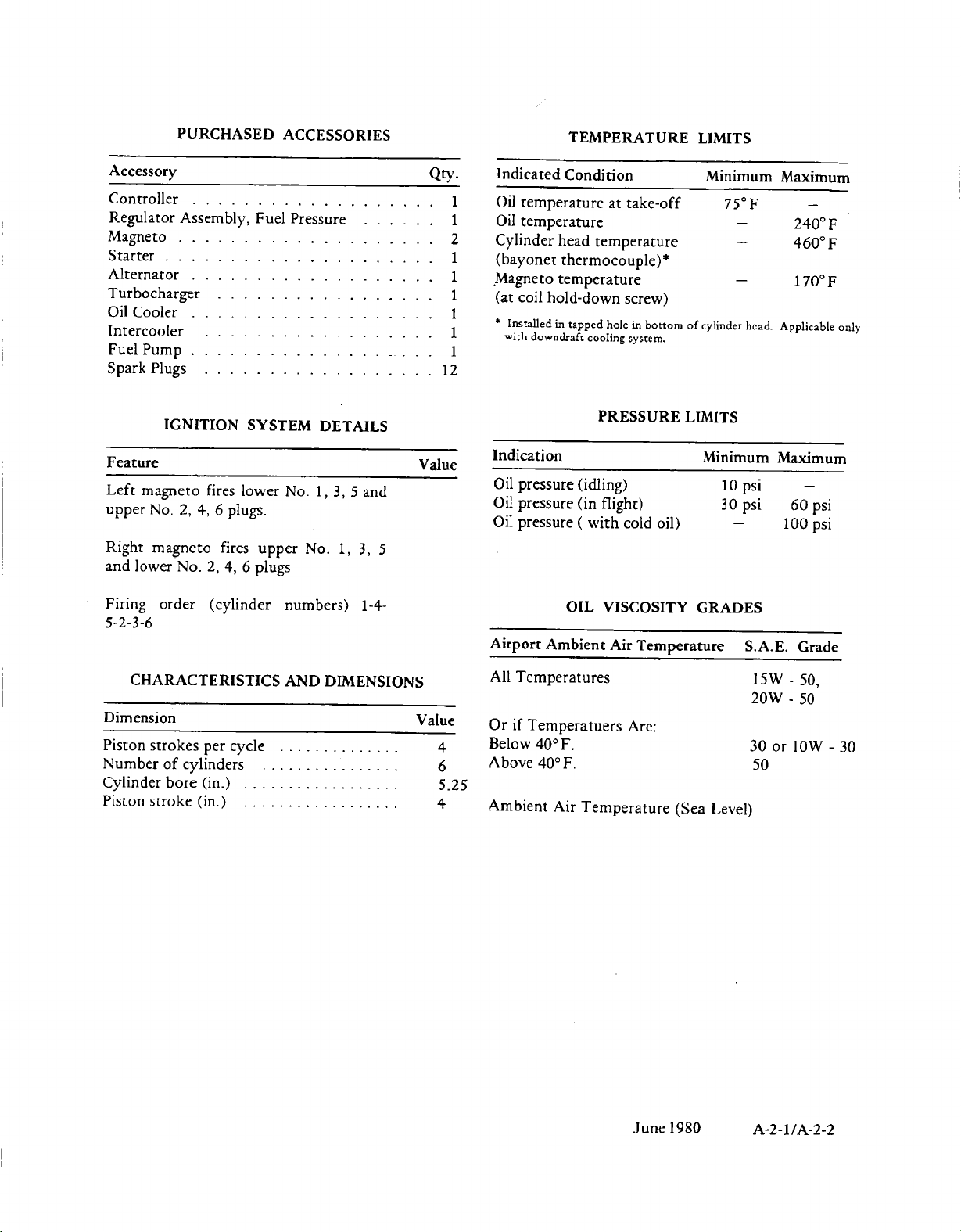
PURCHASED
ACCESSORIES
TEMPERATURE
TMEAUELMT
LIMITS
Accessory
Controller...................
Regulator
Magneto.
Assembly,
...................
Starter.....................
Alternator...................
Turbocharger.................
Oil
Cooler
...................
Intercooler..................
Fuel
Pump
.1..........
Spark
Plugs.
.................
IGNITION
Feature
Left
upper
Right
and
Firing
magneto
No.
magneto
lower
2,
No.
order
fires
4,
6
plugs.
fires
2,
4,
(cylinder
lower
6
5-2-3-6
Fuel
Pressure......
SYSTEM
No.
upper
plugs
numbers)
DETAILS
1,
3,
No.
1,
5
and
3, 5
1-4-
.
Qty.
12
Value
1
1
2
1
1
1
1
1
Indicated
Oil
temperature
Oil
temperature
Cylinder
(bayonet
Magneto
(at
coil
*
Installed
with
downdraft
Indication
Oil
pressure
Oil
pressure
Oil
pressure
Airport
Condition
at
head
temperature
thermocouple)*
temperature
hold-down
in
tapped
holc
cooling
PRESSURE
(idling)
(in
flight)
(
with
OIL
VISCOSITY
Ambient
Air
take-off
screw)
in
bottom
system.
of
LIMITS
cold
oil)
Temperature
Minimum
75F
-
-
-
cylinder
hcad.
Minimum
10
psi
30
psi
-
GRADES
S.A.E.
Maximum
-
0
240
F
0
460
F
170F
Applicable
Maximum
-
60
psi
100
psi
Grade
only
CHARACTERISTICS
Dimension
Piston
Number
Cylinder
Piston
strokes
stroke
of
cylinders
bore
per
(in.)..........
(in.)
cycle........
.........
.
.
.
AND
DIMENSIONS
.
.
All
Va
due
4
6
Temperatures
Or
if
Temperatuers
Below
400
Above
400
Are:
F.
F.
15W
20W
30
50
or
-
50,
-
50
10W
-
30
5.25
.
.
.
.
4
Ambient
Air
Temperature
June
(Sea
1980
Level)
A-2-1/A-2-2
SECTION
III
3-1.
a.
appearance
illustrated
information
Lubrication
b.
ings
form
ings
the
throughout
1.
line
bearings
cision,
main
the
propeller
through
governor
into
main
starter
2.
case
pads
necting
pad
attaching
mount
crankcase
pad
CONSTRUCTION.
GENERAL.
CRANKCASE.
are
joined
the
(with
"left
Bosses
bored
steel-backed,
bearing
crankcase
lateral
the
bearing,
shaftgear.
Cylinder
are
on
rod
has
pad
is
located
of
engine
in
Section
will
Charts.
along
complete
studs
crankcase"
this
publication.
molded
in
the
for
the
inserts.
halves
driveshaft.
bosses
drive
shaft.
right
crankcase,
to
mounting
further
the
right
to
work
six
studs
cylinder
is
located
at
the
lower
on
The
parts
IV,
be
found
Two
the
crankcase.
and
inserts)
and
in
assembled
camshaft
lead-alloy
Provision
at
the
Precision
for
A
support
forward
crankcase
on
and
base
front
the
right
and
Chapter
aluminum
vertical
will
the
the
crankcase
and
top
the
needle
to
the
the
pads
than
a
separate
two
flanges.
on
the
corner.
crankcase
GENERAL
arrangement
components
A.
Additional
in
the
Limits
alloy
The
be
"right
castings
seats
lined
has
front
guides
tappets
bearing
right
front
on
the
to
permit
through
side
center
crankpin.
plane
individual
referred
crankcase"
castings
to
for
the
crankshaft
been
made
to
support
are
and
for
is
pressed
of
the
end
the
left
corresponding
each
bolts
The
governor
of
the
The
alternator
at
the
DESCRIPTION
and
to
and
are
and
cast-
cast-
to
are
form
pre-
the
bored
the
rear
of
the
crank-
con-
Each
for
left
front.
to
as
in
specific
thread
spark
special
solid
spring
semi-circular
grooves.
steel
machined,
are
bosses.
pressed-in
sockets
of
steel
ball
The
bead
ring.
spring,
d.
draulic
crankcase
overhead
reservoirs
the
pushrod
the
bushings.
oil,
valve
cates
the
crankcase
are
rubber
the
returning
barrel
inserts
plug
heat
valve
retainers
Valve
cadmium
held
in
Valve
and
tubes
ends
pushrod
at
the
The
washer,
VALVE
valve
system,
drilled
Each
through
stem.
the
valve
sealed
seals.
assembly.
diameters.
are
holes.
and
stem
tips
are
keys
rocker
plated.
chrome
place
rockers
bronze
rocker
and
which
bead
inside
housings
cylinder
at
seal
lifters,
main
ends
rockers
valve
a
The
stems
through
to
cylinder
Drain
oil
are
galleries,
the
oil
to the
Valve
guides
Special
installed
Exhaust
corrosion-resistant
are
hardened.
locked
which
covers
plated
by
screws
are
bushings,
faces.
pressed
center
are
end
the
crankcase
ring
and
MECHANISM.
under
the
lifter
lifters.
is
forced
and
the
rocker
nozzle,
spray
and
the
heads
holes
in
sump.
in
valves
to
the
engage
are
Rocker
steel.
in
the
steel
hardened
Pushrods
in,
hardened,
drilled
beaded
retains
end
a
second
pressure
is
divided
guide
The
through
groove
directs
towards
from
springs.
pushrod
and
valve
18mm
upper
stems
The
a
oil
the
lifter
are
then
helical
are
faced
material.
The
by
in
stamped
shafts
rocker
cylinder
forgings
are
forged
for
oil
steel
washer
retains
washer.
Oil
fed
between
surfaces
which
the
pushrods
between
a
portion
the
rockers
Oil
is
returned
housings
crankcase
guides
reamed
coil
and
lower
with
The
outer
valve
tapered,
the
stem
sheet
are
fully
shafts
rocker
with
pushrod
composed
steel
passages.
tubes.
The
and
seal
a
heavy
to
from
and
reaches
their
of
respective
lubri-
which
direct
a
hythe
the
the
to
its
to
by
3.
breather
with
breather
crankcase.
C.
are
prior
the
The
a
CYLINDERS.
heated
to
steel
crankcase
consisting
side
extension
assembly
and
the
head
alloy
barrel
of
is
valve
being
interior
a
tube
for
pressed
The
seats
screwed
to
make
is
ventilated
and
baffle
hose
attachment.
into
aluminum
and
guides
and
the
permanent
the
alloy
are
shrunk
by
assembly
upper
heads
installed
onto
head
The
left
a
e.
forging
faces
journals
The
spline
reduction
the
on
crankshaft
CRANKSHAFT.
is
of
front
which
propeller
the
front
machined
the
and
crankpins
end
mates
gear.
driveshaft
for
has
The
all
over
crankcheeks.
are
of
the
crankshaft
with
a
The
reduction
which
attachment
side
blades
six-throw
except
The
nitrided
quill
shaft
gear
has
of
the
projecting
steel
for
some
main
after
grinding.
has
an
to
drive
in
turn
a
flange
propeller.
from
alloy
sur-
bearing
internal
the
drives
formed
The
the
A-3-1
crankcheeks
of
third
order
counterweights
torsional
onto
A
snythetic
the
castings
crankshaft
f.
connecting
bushings
same
end.
limited
g.
ings
lindrical
shaft
built
and
ring
manufactured
cast
machined.
piston
Piston
permanently
variation
h.
machined
gear
journals
the
crankcase
passage.
unequally
relation
with
gear.
vibration.
the
crankshaft
crankshaft
in
the
by
CONNECTING
and
type
Weight
to
1/2
PISTONS.
or
forgings.
relief
counterweights.
since
ring
assembly
model.
steel
insert
Because
configurations
pins
is
CAMSHAFT.
on
mount
are
front
journal
cross
The
spaced
to
the
camshaft
and
are
counterweights.
on
rubber
is
seated
front
a
helical
rods
have
two
identical
as
the
main
variation
ounce.
Pistons
The
cuts
1975
incorporate
Some
engines
with
into
are
full
floating
forged-in
limited
flange
hardened
the
four
journals,
at
passes
passage
camshaft
bolts
camlobes.
gear
to
machined
their
pins
The
crankshaft
and
is
located
oil
seal
shaft
exit,
spring
RODS.
split
bearings)
of
two
are
skirts
at
the
All
GTSIO-520
replacing
in
a
piston
which
of
the
weight
are
aluminum
1/2
ounce
A
steel
the
rear
and
ground.
engine
gear
to
locate
A
and
for
Oscillation
dampen
which
between
and
inside
The
bronze
precision
rods
in
aluminum
are
solid
bottom
a
four
the
current
which
the
top
difference,
not
to
ground
in
alloy
nine
camlobes
end.
A
oil
to
the
is
attached
its
cluster
drives
the
installation
crankshaft
gear
is
by
a
dowel.
is
stretched
the
crankcase
is
sealed
the
seal
"I"
beam-type
piston
inserts
at
the
crankpin
any
one
alloy
and
have
to
clear
series
(4)
ring
original
production
incorporates
ring
groove
be
intermixed.
steel
tubes
plugs.
opposite
forging
The
lobes
groove
from
the
left
crankcase
by
timing
gear
is
the
fuel
of
shrunk
over
to
cavity.
(of
bay
cast-
crank-
engines
piston
five
are
these
with
Weight
bays.
and
the
and
around
right
four
mark
bolted
pump
the
the
pin
the
cy-
(5)
in
a
is
is
is
tappets
from
newer
shoulders
the
1/16"
3-2.
a.
the
(16),
the
turned,
wormwheel
shaftgear
(20)
disengaging
used
(1)
1.
mitted
idler
2.
drive
on
splines
3.
the
the
with
transmits
tachometer
bevel
drives
4.
crankshaft
shaft
quill
propeller
is
the
design,
O.D.
for
FUNCTIONAL
GEAR
engine
through
crankshaft
the
is
to
transmit
to
the generator
Torque
by
gear
The
gears
the
crankcase
of
The
camshaft
oil
pump
internal
gear
the
The
drive
shaft
that
center
which
roughly
The
socket
the
old
TRAIN.
torque
adapter
gear
clutch
hub
(21).
returned
the
the
(12)
and
idler
(14,
magneto
fuel
cluster
and
splines
torque
drive
(6)
governor
internal
(2)
gear
(23).
shaft
gear
the
ball
nearly
must
half
way
hole
and
1/8"
SYSTEMS.
Figure
is
transmitted
components
(1).
spring
and
grips
After
the
to
its
starter.
torque
drive
from
the
crankshaft
camshaft
gear
15).
Optional
upper
drive
pump
drive
gear
tachometer
of
to
the
oil
gear
on
the
front
driven
splined
transmits
(24)
through
The
drive
(25).
socket
to
use
between
diameter
for
As
the
(20)
the
engine
normal
The
shaftgear
from
pulley.
crankshaft
gear
gear
(12)
rear
are
gears.
gear
(3).
the
camshaft
pump
(1
1).
bevel
torque
an
gear
of
the
the
O.D.,
the
new
the
differences
the
new.
A-4-8.
When
from
(17
wormwheel
is
tightened
knurled
the
(1)
drives
accessories
The
drive
The
of
gear
front
(24)
drum
is
started,
position,
(21)
crankshaft
(2)
directly
(3)
the
driven
(22)
is
splined
gear
gear
drive
gear
governor
the
camshaft
(7).
end
to
the
externally
then
old
tapered
while
snap
center
starting
the
thru
onto
is trans-
magneto
mounted
by
internal
driven
(8)
(3)
(9)
of
propeller
splined
drives
ring,
starter
21)
(19)
of
spring
thus
is
now
gear
to
the
end
mates
and
and
drive
the
the
the
and
are
to
is
the
the
by
of
(4)
i.
TAPPETS.
tappets
complete
Section
the
figure
snap
discernible
A-3-2
XIII.
tappets
A-4-10.
ring,
may
be
disassembly
The
are
described
Current
which
difference
MARCH
The
removed
of
the
construction
in
tappets
is
red
between
1981
barrel-type
and
replaced
engine,
paragraph
in
as
and
incorporate
color.
the
hydraulic
without
described
operation
A-3-1d
The
new
and
a
most
of
and
new
old
b.
in
1 .
sump.
oil
being
pump
directed
LUBRICATION
The
engine
The
oil
suction
tube,
continually
gears.
From
to
the
is
sucked
to
oil
SYSTEM.
oil
supply
from
the
oil
displaced
the
pump
filter
is
the
pump
by
the
gear
chamber
Figure
contained
sump
through
to
fill
the
rotation
chamber,
and
A-4-9
the
in
the
the
volume
of
the
oil
tacho-
is
meter
clogged,
permitting
the
passage
any time,
preset,
to
2.
directed
filter.
adapter
From
oil
control
or
depends
engine
From
to
mechanisms.
through
driven gears.
oil
bearings,
valve
Oil
a
pad.
through
directed
the
propeller.
drive
oil
spring-loaded
the
inlet
From
A
the
cooler.
valve
directly
oil
the
the
to
the
mechanisms
is
introduced
drilled
From
center
the
filter
leads
the
to
by-pass
in
filter
on
right
right
a
camshaft
passage
a
return
to
gear.
spring-loaded
oil
to
flow
outlet.
to
the
oil
pressure
side
of
the
the
outlet
the
full
valve
the
event
discharge
Oil
passing
is
directed
to
the
gallery
the
oil
temperature
crankcase
side
Oil
is
directed
passage,
Passages
main
crankshaft
and
to
and
the
governor,
port
the
oil
transfer
of
the
propeller
If
the
filter
by-pass
from
From
the
oil
pressure
exceeds
relief
valve,
pump.
side
flow
replaceable
is
incorporated
the
element
port,
through
either
in
the
temperature.
is
maintained
oil
valve
lifter
from
to
the
from
the left
bearings,
the
governor
the
propeller
port
in
oil
re-enters
in
the
mount
tube,
should
valve
the
gear
oil
filter
relief
the
oil
of
the pump,
becomes
oil
is
directed
the
oil
through
left
crankcase.
In
gallery,
guides
the
propeller
bearings,
valve
drive bearings.
governor
the
governor
which
shaft,
and
will
chamber
outlet,
valve.
limit
is
passed
element
in
the
clogged.
temperature
the
this
manner,
at
oil
is
directed
and
right
driver
gallery
prop
lifter
through
the
crankcase
pad.
The
is
located
on
become
open
If,
of
the
back
oil
oil
filter
to
the
cooler
This
1700
F.
valve
gallery,
and
direct
shaft
guides,
mount
oil
to
the
inner
dome.
Oil
in
the
crankcase
sump
through
to
a
6.
at
is
is
in
the
crankcase
charger
turbocharger
to
an
oil
to
the
scavenge
c.
system
fold
assembly,
air
throttle
include,
capable
pressure
sure.
The
exhaust
a
higher
able
from
charger
body
which
inducted
injector
throttle
the
manifold
intake
ports.
The
turbocharger-to-fuel
provides
discharge
nozzles.
drain
The
turbocharger
left
oil
inlet
through
at
the
separator
pump
INDUCTION
consists
in
of
drop
velocity
ambient
discharge
in
system
body
pressurized
side
of
intake
assembly.
the
induction
40%
effectivity
across
gas
driven
and
side
controls
accordance
fuel
the
riser
to
conditions.
induction
and
holes.
is
gallery
oil
outlet
and
from
inlet.
SYSTEM.
a
turbocharger,
tubes,
In
the
cooler
turbocharger
greater
is
directed
the
with
control
intake
injection
air
from
the
fuel
is
returned
lubricated
directed
a
hose.
these
air
addition
system,
with a static
quantity
air
tubes
to
Oil
port
through
through
The
manifold
most
an
of 6"
supplies
density than
Air
from
to
the
of
the
setting
unit.
From
is
directed
to
system
the
turbocharger
pump
and
to
by
oil
the
turbo-
leaves
a
a
induction
intake
mani-
tubes
models
inter-cooler
cooling
H20
attain-
the
turbo-
air
throttle
air
to
of
the
through
the
cylinder
manifold
injector
the
from
the
hose
hose
and
pres-
air
the
air
at
be
air
3.
is
adapter
idler
4.
conducted
two
shaftgear
clutch
lubricated
crankcase
of
clutch
5 .
by
direct
From
directed
gear
Oil
radial
spring.
the
adapter
spring
Each
individual
a
a
groove
through
bearing,
bearing
from
through
holes
drum
Other
by
this
through
and
sleeve.
cylinder
oil
continuous
idler
to
the
from
and
spray.
a
squirt
in
the
drilled
gear
the two
starter
a
passage
which
bearing
parts
hole
in
a
slot
wall
stream
rear
passages
bearing
magneto
shaftgear
it
of
the
Oil
drains
the
in
and
piston
nozzles.
of
main
in
the
is
sprayed
surface
starter
bottom
the
bottom
These
oil
bearing,
to
the
and
from
bearings.
bearing
shaftgear
onto
under
drive
back
front
is
lubricated
at
the
starter
into
of
nozzles
piston
oil
the
to
the
the
are
the
side
the
In
most installations,
scroll
pressurization
ments.
sonic
is
mately
d.
is
plugs
plugs
mounted
accessory
the
supplies
cylinder
spark
breaker.
feature
The
venturi
six
IGNITION
generated
of
the
of
pad.
front
high
spark
plugs,.
The
to
in
turbo-bleed
which
pounds
and
right
the
left
on
the
While
of
the
voltage
plugs
it
double
the
provide
addition
limits
of
air
SYSTEM.
distributed
side
side
front
the
left
current
and
is
also
breaker
turbocharger
turbo-bleed
to
the
air
is
provided
the
bleed
per
minute
High
to
cylinders
cylinders
of
the
left
magneto,
crankcase
the
lower
equipped
magneto
has
air
engine
through
air
to
at
sonic
voltage
the
upper
and
lower
by
a
right
mounted
accessory
to
the
upper
right
with a double
serves a dual
a
dual
for
cabin
require-
approxi-
flow.
current
spark
spark
magneto
crankcase
on
pad,
left
cylinder
A-3-3
a
purpose.
breaker
a
shower
As
disengaged,
are no
running
magnetos.
furnishes
retarded
cranking
plugs
through
assemblies.
magnetos
by
e.
1.
simple,
the
multi-nozzle,
controls
change
combination of
correct
mixture
ed
any
The
vane
system
2.
function
engine
pressure
control
for
other
Main
and
the
manifold
the
air-flow
valve
the
fuel-air
blast
pressure
When
and a starting
of
the
engine
the
longer
on
The
electrical
ignition
speed.
through
braided,
These
by
nuts.
FUEL
GENERAL.
low
intake
fuel
fuel; one
metering
metering
fuel
valve
fuel
in
throttle
relation
control
pressure,
combination
continuous
pump.
fuel
except
FUEL -AIR
of
air
for
elements
for
fuel
fuel
enters
passes
to
valve
to
fuel-flow.
determines
pump.
control unit
air
cooled to
switch,
high
pressure
the
intake
proper
cranking
vibrator
voltage
is
started
retard
breaker
transmitting
the
advance
battery
current
starting,
Spark
is
high
tension
flexible, shielded
assemblies
coupling
INJECTION
continuous
flow
both,
for
of
metering.
the metering
valve
and
valve
nuts
The
system
port
in
to
match
position,
causes changes
to
engine
and a flow
are
provided
of altitude
flow
system
There
the
engine -driven
fuel-air
and
fuel-air
in
this
which
the
control
controls
nozzles.
to
the
The
the
amount
The
fuel
is
enclosed
help
connected
the
engine,
are
sparks
to
and
cranking
and
spark
breakers
operated
to
the
regardless
transmitted
cables
are
and
to
SYSTEM.
fuel
injection
of
injecting
the
cylinder
type
flow
engine
engine
airflow.
gage,
for
and
uses a typical
no
are
is
running
CONTROL
control unit
set
to
unit,
prevent
the
ratio.
one
for
fuel
unit
valve.
the
fuel
A
linkage
air
throttle
position
of
control
in a shroud
vapor lock. A fuel
to
the
the retard
in
effect,
start
starting
and
starting
connected
the spark
indicating
precise leaning
power
There
for
mixture
through a strainer
The
of
fuel
portions
fuel
causing
the
engine.
motor
vibrator
the
engine
from
vibrator
magneto
of
engine
to
the
which
conduit
to
system
fuel
It
head.
system
airflow.
in
fuel
UNIT.
metered
passed
which
speed,
fuel
flow
A
manual
meter-
setting.
rotary
parts
in
pump.
is
to
control
are
air,
and
and
position
to
connecting
proportions
the
mixture
returned
of
control unit,
both
for
spark
pass
the
plugs
is a
into
is a
Any
or
this
The
fuel
three
two
the
the
the
and
in
of
to
actuates
operate
pressure
pump
is
switch
is
3.
the
the
for
cylinder
bleed
supplies pressurized
arrangement
breaking
fuel
acceleration
with a letter
Replacement
4.
unit,
provides
a
individual cylinders.
In
valve
at
close
simultaneously. A piston type
insure
before
restrictions
fine mesh
additional
against
5.
is a positive-displacement,
has a shaft
section
swirl well
separated
fuel
the
jet
returned
engine-driven,
pump
more
fore,
is
constant
provided
to
at a high
drops
switch
to
operate.
FUEL
fuel
manifold,
metered
each
cylinder.
heads
and
the
lines
FUEL
fuel
is
a
the
fuel
raises
the
that
fuel
screen is
dirt
FUEL
of
the
by a swirling
is
fed
top center
of
fuel and
to
flow
fuel
than
a
relief
fuel
so
cause
fuel
solidly
of
delivered
central
or
individual cylinder
the
flow
to
protection
or foreign
for
of
to
that
the
auxiliary fuel
speed
if
the
engine-driven
5
below
must
DISCHARGE
to
These
outside
nozzle
aids
in
high
vacuum
the
on
the
nozzles
MANIFOLD.
manifold, a diaphragm
lowers,
plunger fully
starts.
fuel
included
INJECTION
connection
engine.
the
vapor
the
pump. The
of
the
is
fed
the
fuel
changes
proportionally.
required
is
valve
pump
the
PSI.
be
ON
for
individual
the
fuel
nozzles
each
pressurization
air
to
the
vaporization
at
filled
and
engine.
hex
must
match.
From
to
the
point
for
fuel
by
Thus,
flow
in
in
of
the
matter.
PUMP.
rotating
to
Fuel
enters
separator.
motion
swirl
well
into
the
tank.
in
engine
by
is
provided
pressure.
auxiliary
NOZZLES.
discharge
intake
nozzle.
Nozzles
of
fuel
dividing
pressure,
check
opens
there is
the
vapor is
vapor
Since
The
pump
The
auxiliary
the
fuel
pressure
fuel
lines
nozzles,
are
installed
valve.
arrangement
The
air bleed
of
fuel
idle,
maintains
ready
the
the accessory
so
by a small
the
A
pump
are
the
nozzle
the
manifold
and plunger
fuel
supply
valve
the
no
fuel
manifold.
fuel
injection
The
vane
the
Here,
that
return
the
speed
pump
engines.
to
check
pressure
for
stamped
fuel
fuel
to
serves
outlet
unbalance
manifold
fuel
pump
vapor
only
drawn
pressure
pump
affect
maintain
to
pump
fuel
From
carry
one
in
the
An
air
and
by
the
instant
body.
control
which
to
the
open
port
ports
nozzles
pump
type.
drive
at
the
liquid
from
line
and
total
supplies
There-
valve
can
or
to
A
as
It
is
is
a
is
A-3-4
bypass
starting.
pump
automatically
is
failure,
ON.
Incorporated
the
In
engine-driven
case
of
engine-driven
the
auxiliary
when
the
on
the
fuel
fuel
auxiliary
fuel
injection
fuel
pump
fuel
pump
injection
pump
injection
will
pump
for
operate
switch
is
a
variable
pump.
charger
controls
altitude.
at
orifice
The
aneroid
discharge
the
pressure
controlled
is
pressure.
from
by
an
controlled
The
the
fuel
aneroid
by
the
variable
injection
on
the
super-
orifice
pump
A-3
-5
/A-3-6
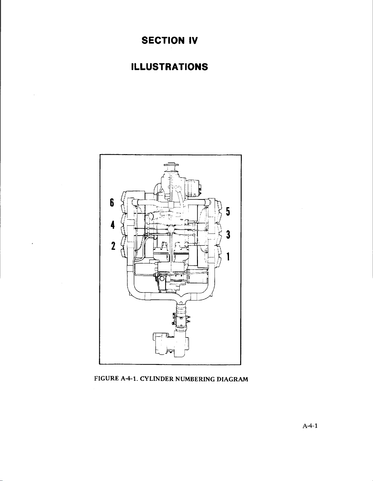
6
SECTION
IV
ILLUSTRATIONS
5
4
2
FIGURE
A4-1.
CYLINDER
NUMBERING
3
1
DIAGRAM
A-4-1
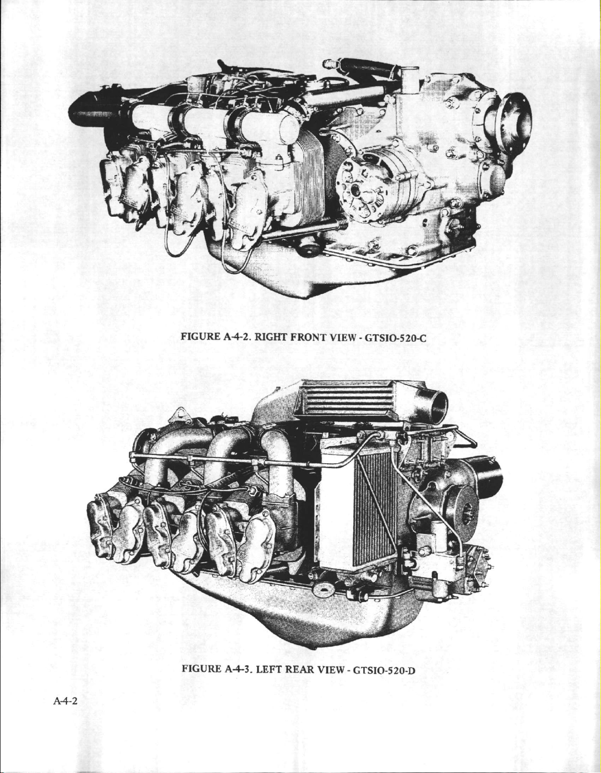
FIGURE
A-4-2.
RIGHT
FRONT
VIEW
-
GTSIO-520-C
A4-2
FIGURE
A-4-3.
LEFT
REAR
VIEW
-
GTSIO-520-D
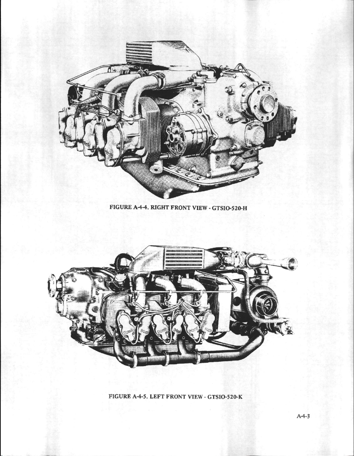
FIGURE
A-44.
RIGHT
FRONT
VIEW
-
GTSIO-520-H
FIGURE
A-4-5.
LEFT
FRONT
VIEW
-
GTSIO-520-K
A-4-3
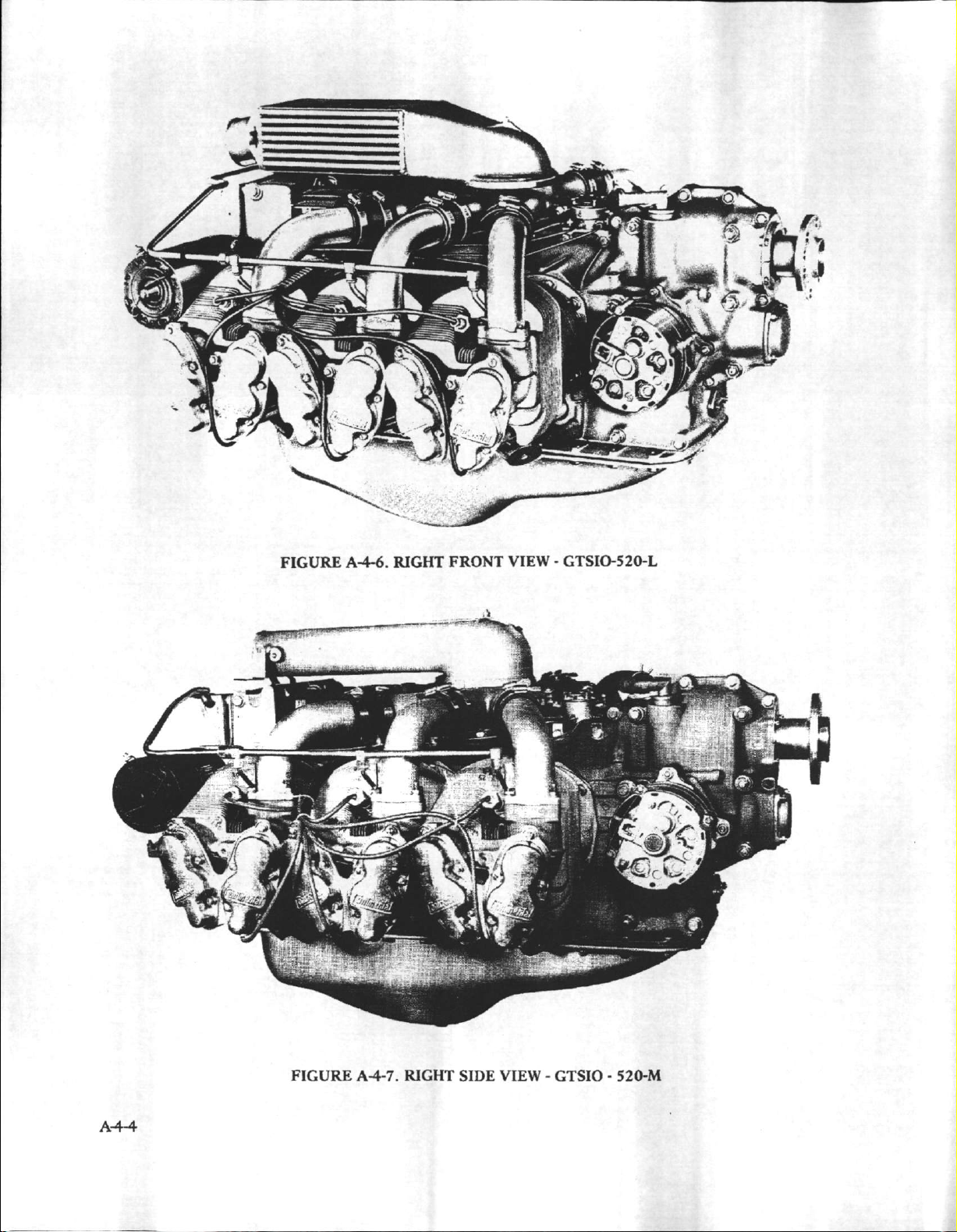
FIGURE
A-4-6.
RIGHT
FRONT
VIEW -GTSIO-520-L
A4-4
FIGURE
A-4-7.
RIGHT
SIDE
VIEW
-
GTSIO -520-M
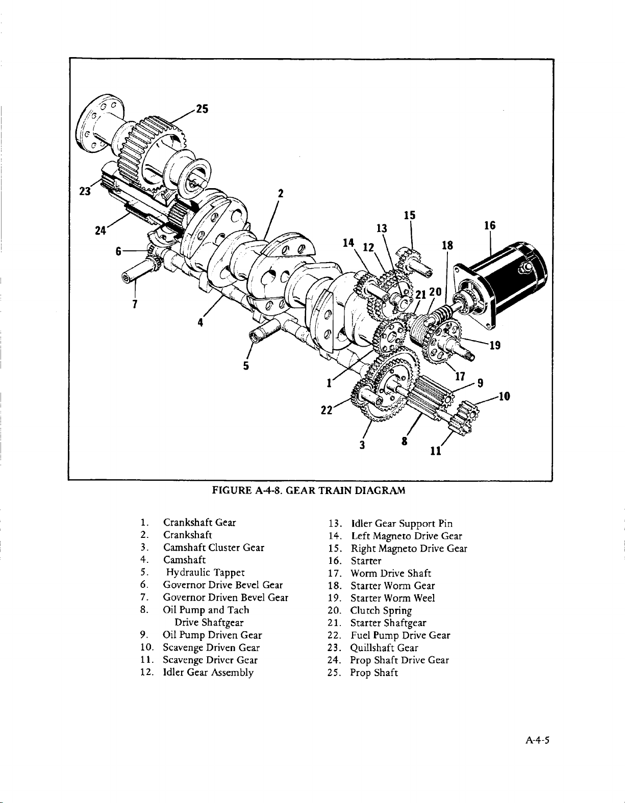
24
.25
2
18
4
5
1.
Crankshaft
2.
Crankshaft
3
.
Camshaft
4.
Camshaft
5.
Hydraulic
6.
Governor
7.
Governor
8.
Oil
Pump
Drive
Shaftgear
9.
Oil
Pump
10.
Scavenge Driven Gear
11.
Scavenge
12.
Idler
Gear
FIGURE
Gear
Cluster
Tappet
Drive
Driven
and
Tach
Driven
Driver
Assembly
Gear
Bevel
Bevel
Gear
Gear
A4-8.
Gear
Gear
22
GEAR TRAIN
13.
14.
15.
16.
17.
18.
19.
20.
21.
22.
23.
24.
25.
DIAGRAM
Idler Gear
Left
Magneto
Right
Magneto
Starter
Worm Drive
Starter
Starter
Clutch
Starter
Fuel Pump
Quillshaft
Prop
Prop
Worm Gear
Worm
Spring
Shaftgear
Gear
Shaft
Shaft
Support
Drive
Drive
Shaft
Weel
Drive
Drive
11
Pin
Gear
Gear
Gear
Gear
A-4-5
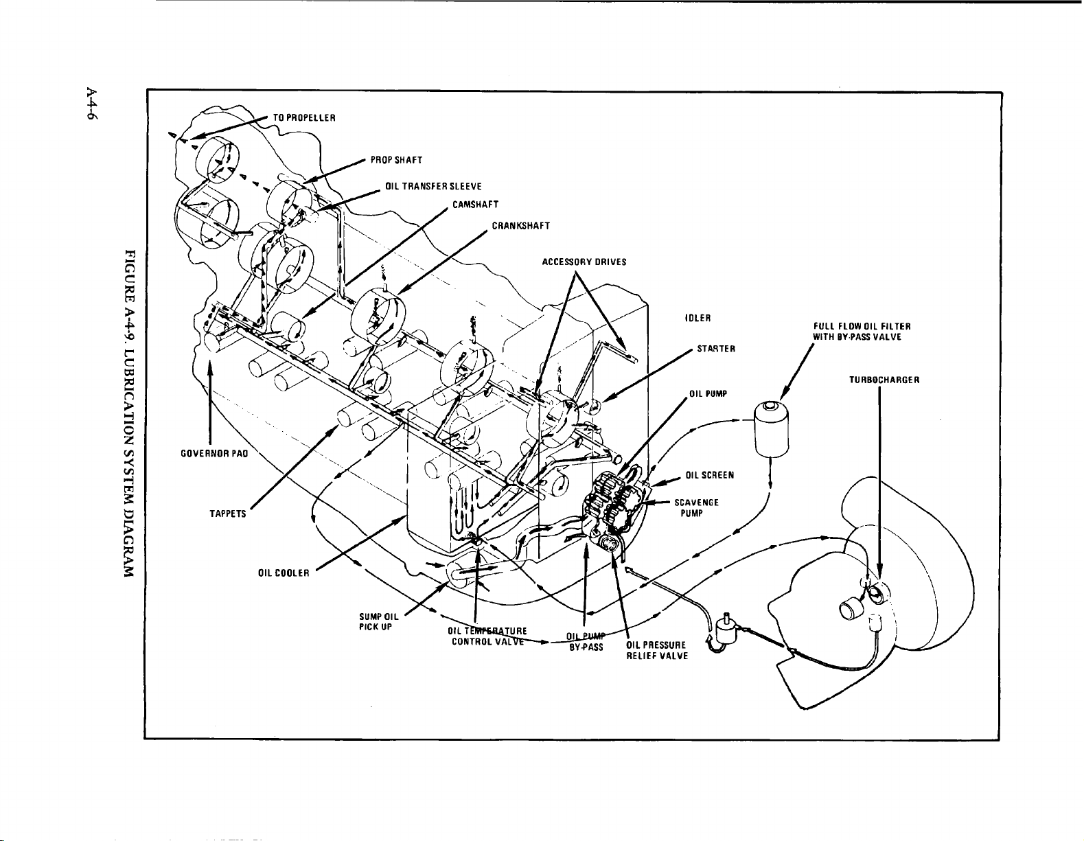
A-4-6
FIGURE
A-4-9.
LUBRICATION
SYSTEM
DIAGRAM
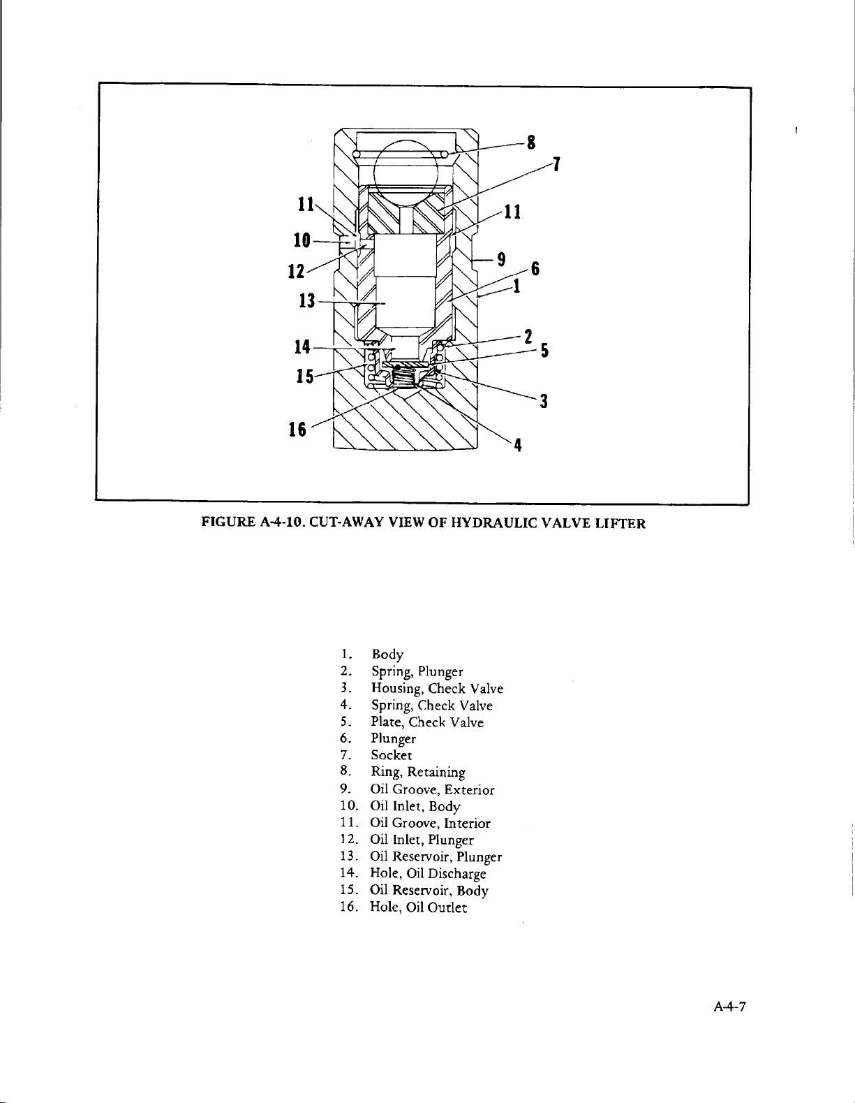
FIGURE
A4-10.
CUT-AWAY
1.
Body
2.
Spring,
3.
Housing,
4.
Spring,
5.
Plate,
6.
Plunger
7.
Socket
8.
Ring,
9.
Oil
10.
Oil
11.
Oil
1
2.
Oil
13.
Oil
14.
Hole,
15.
Oil
16.
Hole,
VIEW
OF
Plunger
Check
Check
Check
Retaining
Groove,
Inlet,
Body
Groove,
Inlet,
Plunger
Reservoir,
Oil
Discharge
Reservoir,
Oil
Outlet
HYDRAULIC
Valve
Valve
Valve
Exterior
Interior
Plunger
Body
VALVE
LIFTER
A-4-7
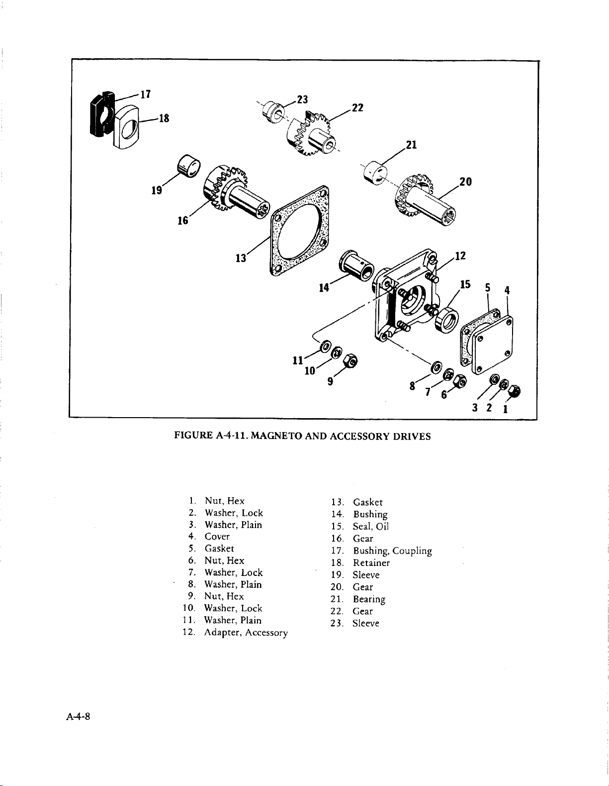
A-4-8
FIGURE
1.
2.
3.
4.
5.
6.
7.
8.
9.
10.
Washer,
11.
Washer,
12.
Adapter,
A-4-11.
Nut,
Hex
Washer,
Washer,
Cover
Gasket
Nut,
Hex
Washer,
Washer,
Nut,
Hex
MAGNETO
Lock
Plain
Lock
Plain
Lock
Plain
Accessory
AND
ACCESSORY
1
14.
15.
16.
17.
18.
19.
20.
21.
22.
2 3.
3.
Gasket
Bushing
Seal,
Oil
Gear
Bushing,
Retainer
Sleeve
Gear
Bearing
Gear
Sleeve
DRIVES
Coupling

11
6
FIGURE
1.
Gasket,
2.
Plug
3.
Screw,
4.
Washer,
5.
Washer,
6.
Sump
7.
Gasket,
8.
Screw,
9.
Screw,
10.
Washer,
11.
Tube
12.
Gasket,
A4-12.
OIL
Annular
Ilex
Head
Lock
Plain
Assembly,Oil
Oil
Sump
Hex
Head
Hex
Head
Plain
Assembly,
Suction
SUMP
Suction
Tube
A4-9
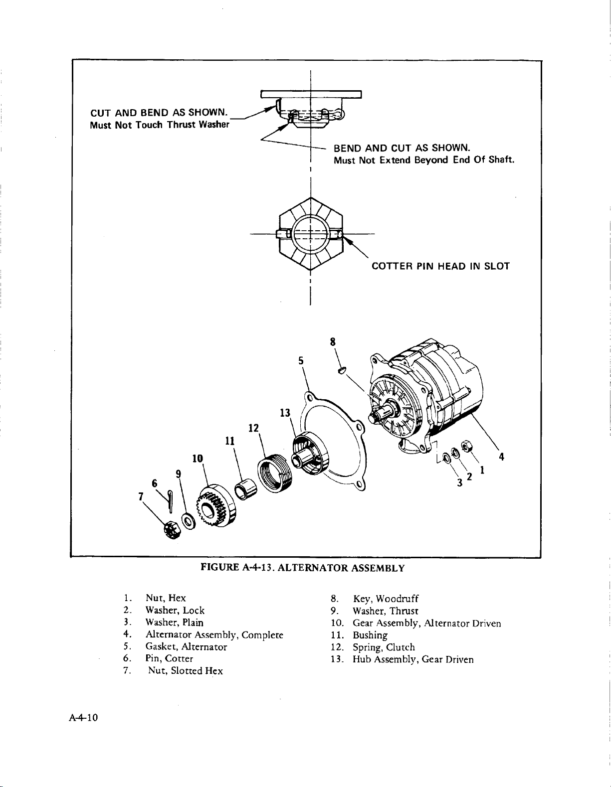
CUT
Must
AND
Not
BEND
Touch
AS
SHOWN.
Thrust
Washer
AND
CUT
Not
Extend Beyond
AS
SHOWN.
End
Of
Shaft.
OTTER
PIN HEAD
IN
SLOT
8
5
12
11
10
7
4
A-4-10
2.
4.
5.
6.
7.
1 .
3
.
Nut,
Hex
Washer,
Washer,
Alternator
Gasket,
Pin,
Cotter
Nut,
Slotted
FIGURE
Lock
Plain
Assembly,
Alternator
Hex
A4-13.
Complete
ALTERNATOR
8.
9.
10.
11.
12.
13.
ASSEMBLY
Key,
Woodruff
Washer,
Gear
Bushing
Spring,
Hub
Thrust
Assembly,
Clutch
Assembly,
Alternator
Gear
Driven
Driven
 Loading...