

Teledyne Cetac Technologies SPM-700 Installation Manual
SPM-700 Syringe Pump Module
Manual Part Number 610108 Rev 0
Installation Guide

COPYRIGHT
© 2018 Teledyne CETAC Technologies
610108 Rev 0 , December, 2018
Teledyne CETAC Technologies authorizes its
customers to reproduce, transmit, or store
this document in its entirety, including this
page, for the express purpose of installing,
operating, or maintaining the product
described herein.
Teledyne CETAC Technologies
Customer Service & Support
14306 Industrial Road
Omaha, Nebraska 68144, USA
Phone (800) 369-2822 (USA only)
Phone (402) 733-2829
E-mail cetacservice@teledyne.com
REVISIONS
Teledyne CETAC Technologies strives to
provide the scientific community with an
unparalleled combination of effective
technology and continuing value. Modular
upgrades for existing instruments will
continue to be a prime consideration as
designs progress.
Teledyne CETAC Technologies reserves the
right to revise this document and/or improve
products described herein at any time without
notice or obligation.
TRADEMARK ACKNOWLEDGEMENTS
Windows is a registered trademark of
Microsoft Corporation in the United States and
other countries.
PharMed and Tygon are registered
trademarks of Saint-Gobain Performance
Plastics.
DuPont™ and Viton® are trademarks or
registered trademarks of E.I. du Pont de
Nemours and Company.
Superthane is a registered trademark of
NewAge Industries, Inc.
KIMWIPES is a registered trademark and
KIMTECH SCIENCE is a trademark of
Kimberly-Clark Worldwide, Inc
All other marks are the property of their
respective owners.

3
Contents
1 Introduction .............................................................................................................. 4
Overview.................................................................................................................................... 4
Chemical Compatibility ....................................................................................................... 4
Operator Qualifications ....................................................................................................... 5
Choosing a Location for Installation ............................................................................. 5
Proximity to the Instrumentation ........................................................................... 5
Space Requirements ...................................................................................................... 6
Power Requirements..................................................................................................... 6
Unpacking the Syringe Pump Module .......................................................................... 6
2 Installing the Syringe Module ............................................................................. 7
Installing the Accessory Module Mounting Blocks ................................................. 7
Mounting the Syringe Pump Modules .......................................................................... 9
Connecting the Tubing ...................................................................................................... 10
Connecting the Power Supply ........................................................................................ 11
Connecting the Syringe Module to the Autosampler ........................................... 11
Connecting the Syringe Module Directly to the Host PC .................................... 12
Connecting a USB Cable ............................................................................................ 12
Connecting a Serial Cable ......................................................................................... 13
Installing a Syringe .............................................................................................................. 13
Starting the Pump ................................................................................................................ 14
Shutting Down the Pump ................................................................................................. 15
3 Maintaining and Troubleshooting the Product......................................... 16
Cleaning the Syringe Module .......................................................................................... 16
Cleaning the Syringe ........................................................................................................... 16
Returning the Product to CETAC for Service ........................................................... 18
Shipping the Product .................................................................................................. 18
Product Warranty Statement ................................................................................. 18
4 Safety and Regulatory Information ............................................................... 19
Safety Characteristics ........................................................................................................ 19
Environmental Characteristics ............................................................................... 19
Electrical Characteristics .......................................................................................... 20
Safety Notices ........................................................................................................................ 20
Power Cord Set Requirements and Maintenance ............................................ 20
Mains Disconnect ......................................................................................................... 21
Mechanical Hazards ................................................................................................... 21
Operating Environment............................................................................................. 21
Explanation of Caution and Warning Notices .................................................. 22
Electromagnetic Interference ........................................................................................ 22
Explanation of Regulatory Marks ................................................................................. 23
4
1 Introduction
Overview
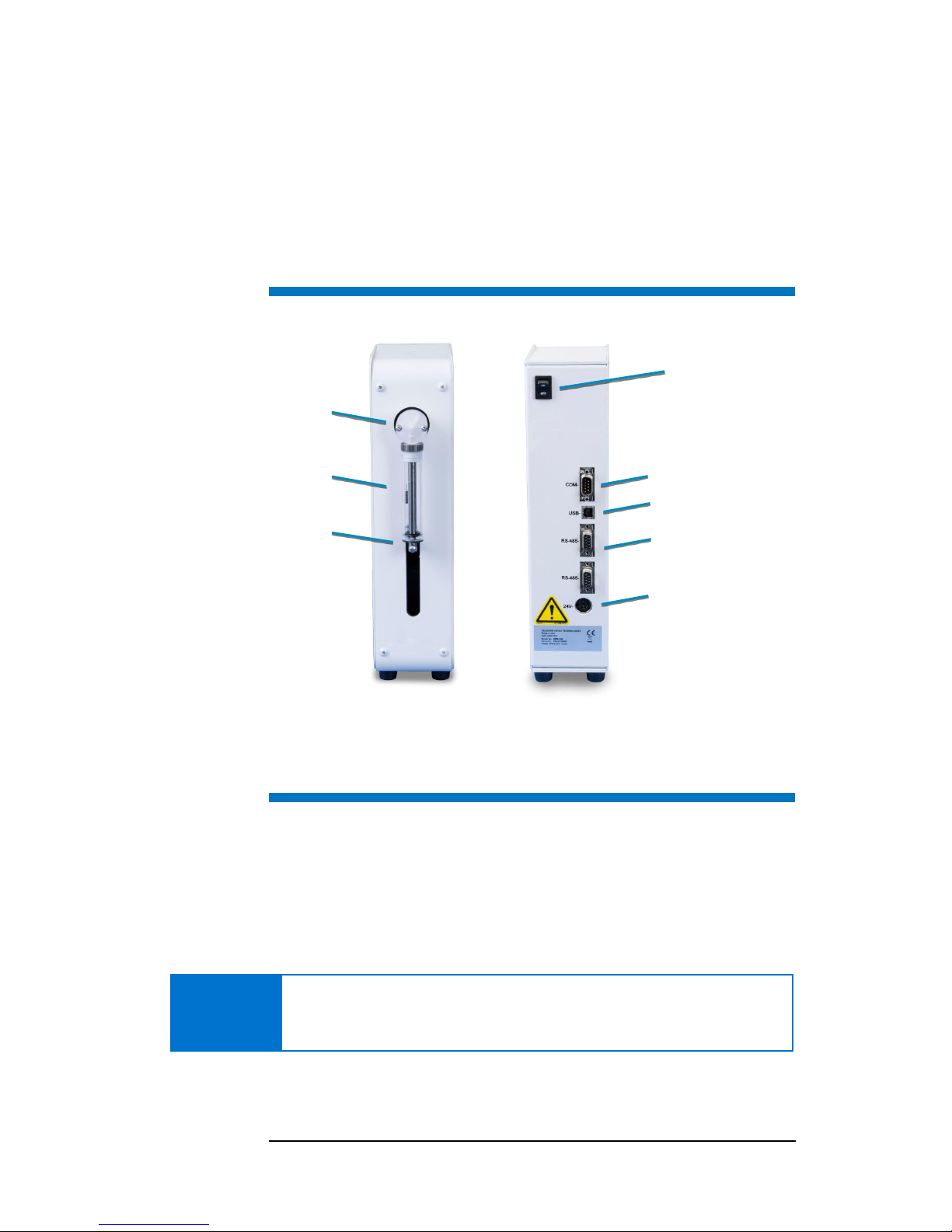
FIGURE 1-1 Front and Back Views.
The color and branding of the module may vary from what is shown here.
Chemical Compatibility
The syringe module is intended for use with sample matrices with the
following characteristics:
low-acid aqueous solutions (up to 1% HNO
3
or HCl)
low-viscosity oils
low to high dissolved solids
The system is not suitable for high viscosity samples.
NOTICE
Avoid use with chemicals which are likely to precipitate or form deposits on
the internal surfaces, such as silver chloride. Samples which contain AgCl may
contaminate the internal surfaces and require the replacement of the tubing.
Wetted components are made of Polyetherimide (PEI) and
Polytetrafluoroethylene (PTFE). When these inert, non-metallic materials are
Power Switch
Serial Port
USB Port
RS-485 Ports
Power Connector
Valve with Input
and Output Ports
Syringe
Plunger
Thumbscrew
5
used at temperatures less than 135°C, they can withstand repeated exposure
to the following substances:
Predominantly aqueous solutions of acids (less than 10%), including HNO
3
and HCl.
Predominantly aqueous solutions of strong bases (less than 10%)
Common organic solvents such as acetone, alcohols, ethyl acetate,
Methylethylketone (MEK), petroleum oils and derived fuels,
tetrachloroethylene, toluene, kerosene and xylene.
NOTICE
DAMAGE FROM CHEMICAL EXPOSURE
Prolonged or repeated exposure to temperatures greater than 135°C and to
the following substances can cause failure of the wetted components:
Acids greater than 10%.
Hydrofluoric acid (HF).
Solutions of concentrated bases (greater than 10% potassium,
ammonium, or sodium hydroxides).
Partially halogenated hydrocarbons or extremely aggressive organic
solvents (chloroform, methylene dichloride, 1,1,2-trichloroethane).
Operator Qualifications
To use this product, you should have a working knowledge of the equipment
with which the syringe module will be used.
WARNING
CHEMICAL INJURY HAZARD
Make sure you know the hazards associated with all of the chemicals you
are using, and take the appropriate precautions. Exposure to laboratory
chemicals may result in serious injury.
Choosing a Location for Installation
Proximity to the Instrumentation
Tubing length affects the time it takes for fluid to reach its destination and the
volume of fluid required. When introducing very small sample volumes (flow
rates less than 50 µL min-1), minimize the length of the connecting sample
tubing. For the introduction of sample volumes to analytical instrumentation
such as ICP-MS, where flow rates of greater than 50 µL min-1 will be employed,
the length of connecting sample tubing between the syringe pump and a
nebulizer is less critical. The syringe module can be mounted on either side of
the autosampler or it may be placed on the workbench.
6
Space Requirements
You will need easy access to the back of the syringe module to reach the power
switch. As a minimum, allow at least 5 cm behind the syringe module for cable
egress, ventilation, and access to the power switch. Always position the
equipment so that it is easy to disconnect the power cord.
Power Requirements
The syringe module receives power through the connection to the external
desktop “brick” power supply. Place the module within 1.2 meters of a power
outlet.
WARNING
SHOCK AND FIRE HAZARD
Use only the provided power supply. The power supply must be plugged into
an outlet which has a protective ground connection.
The power supply must be connected to an AC power source that will not
apply more than 240VAC between the supply conductors and ground. A
protective ground connection is required for safe operation.
Ensure that you position the syringe module so that the plug is easily
accessible (is not blocked) and can be quickly disconnected if needed. In case
of hazard, the power cord should be disconnected from the wall socket. Do not
plug in the power supply until ready to operate the pump.
Unpacking the Syringe Pump Module
Inspect external packaging upon receipt for signs of shipping damage. Inspect
all items during unpacking and notify the carrier immediately of any concealed
damage.
If the system is shipped or removed from storage during cold weather, allow
the equipment to equilibrate to room temperature before opening and
exposing to warm, humid air.
CAUTION
EQUIPMENT DAMAGE FROM CONDENSATION
If condensation forms on or inside the pump module, allow it to dry
thoroughly before connecting it to a power source and operating it. Failure to
do so may cause equipment damage.
NOTE
Keep the factory packaging for use in case the product ever needs to be
returned or shipped to another location.
7
2 Installing the Syringe
Module
The syringe pump module may be placed on the workbench, or it can be
attached to the autosampler using an optional mounting block.
Installing the Accessory Module Mounting Blocks
The syringe pump module can be mounted on an accessory mounting block,
and the mounting block can be installed on either side of the autosampler.
There are two types of mounting blocks. An inside mounting block is designed
to attach directly to the autosampler. An outside mounting block is designed to
attach to an inside mounting block.
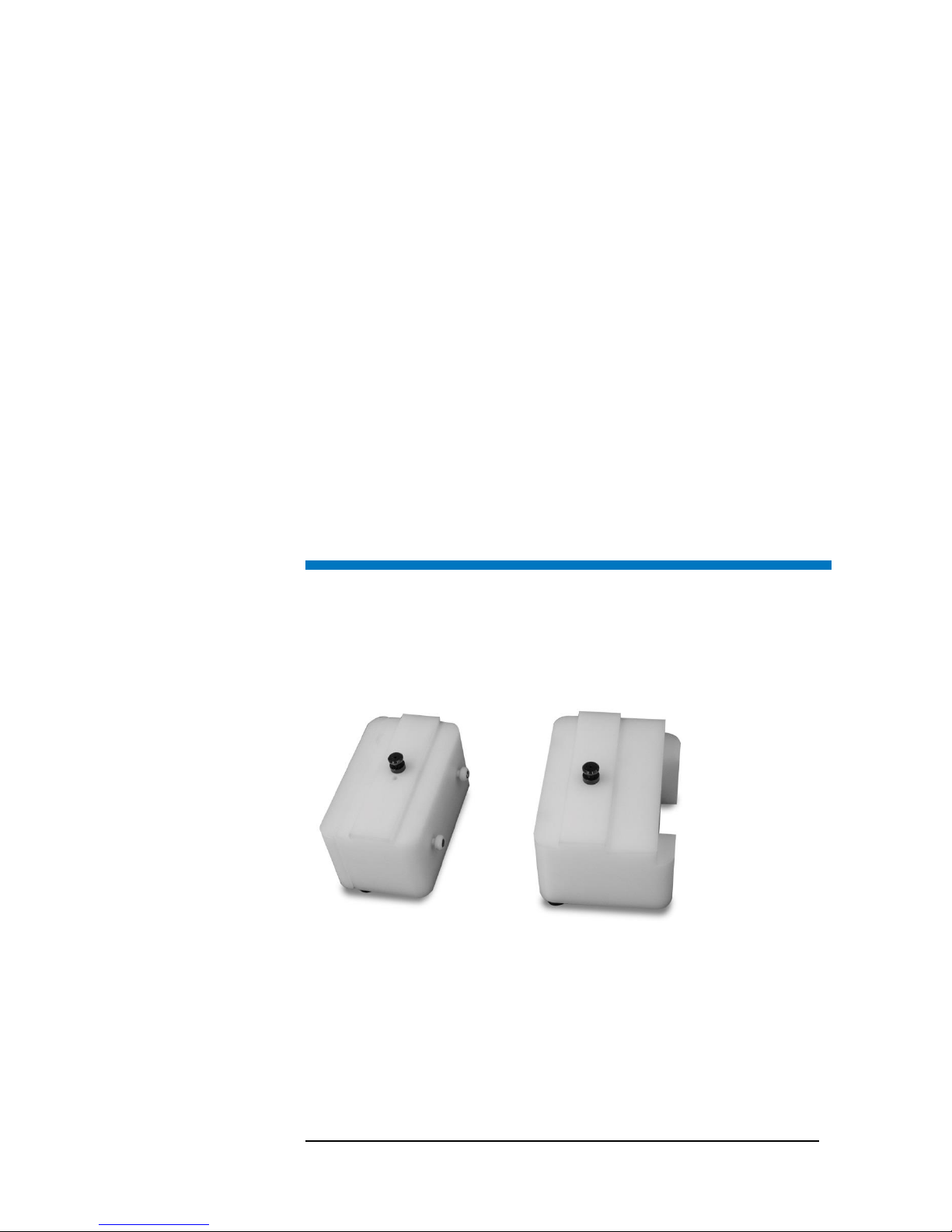
FIGURE 2-1 Mounting Blocks.
You will need a Philips head screwdriver and a set of Allen (hex) wrenches.
1 Turn the power switches on the power supply, autosampler, and syringe pump
module OFF.
2 Place an inside mounting block next to the autosampler on the side where you
want it.
Inside Block
Outside Block
 Loading...