

Teledyne Cetac Technologies ASX-560, ASX-280 Operator's Manual
ASX-560 / ASX-280 Autosampler
Manual Part Number 480215 Rev2
Operator’s Manual

COPYRIGHT
© 2004-2015 Teledyne Technologies
Incorporated. All rights reserved.
480215 Rev2, September, 2015
Teledyne CETAC Technologies authorizes its
customers to reproduce, transmit, or store
this document in its entirety, including this
page, for the express purpose of installing,
operating, or maintaining the product
described herein.
Teledyne CETAC Technologies
Customer Service & Support
14306 Industrial Road
Omaha, Nebraska 68144, USA
Phone (800) 369-2822 (USA only)
Phone (402) 733-2829
Fax (402) 733-1932
E-mail custserv@cetac.com
REVISIONS
Teledyne CETAC Technologies strives to
provide the scientific community with an
unparalleled combination of effective
technology and continuing value. Modular
upgrades for existing instruments will
continue to be a prime consideration as
designs progress.
Teledyne CETAC Technologies reserves the
right to revise this document and improve
products described herein at any time without
notice or obligation.
TRADEMARK ACKNOWLEDGEMENTS
Windows is a registered trademark of
Microsoft Corporation in the United States and
other countries.
PharMed and Tygon are registered
trademarks of Saint-Gobain Performance
Plastics.
DuPont™, Kapton®, Teflon®, Tefzel® and
Viton® are trademarks or registered
trademarks of E.I. du Pont de Nemours and
Company.
Superthane is a registered trademark of
NewAge Industries, Inc.
KYNAR® is a registered trademark of Arkema
Inc.
KIMWIPES is a registered trademark and
KIMTECH SCIENCE is a trademark of
Kimberly-Clark Worldwide, Inc
All other marks are the property of their
respective owners.

3
Contents
1 Introduction ..............................................................................................................7
Overview.................................................................................................................................... 7
About This Manual ................................................................................................................7
Who Should Read This Book...................................................................................... 7
Autosampler Standard Components............................................................................. 8
Additional Equipment Required ...................................................................................10
Optional Accessories ..........................................................................................................11
Chemical Compatibility .....................................................................................................12
Where to Go for More Information..............................................................................13
2 Preparing for Installation ................................................................................. 15
Choosing a Location............................................................................................................15
Space Requirements....................................................................................................15
Work Surface Requirements....................................................................................16
Rinse Solution Requirements...................................................................................16
Liquid Waste Routing Requirements ...................................................................16
Power Requirements...................................................................................................16
Unpacking the Autosampler ...........................................................................................17
3 Installing the Autosampler ............................................................................... 19
Mounting the Tray and Rinse Station .........................................................................20
Mounting the Z-Drive.........................................................................................................21
Attaching the Z-Drive to the Autosampler Arm............................................... 21
Connecting the Rinse Station..........................................................................................26
Waste Rinse Solution..................................................................................................26
Tubing Considerations ...............................................................................................26
Pumped Drain Arrangement...................................................................................27
Gravity Drain Arrangement.....................................................................................31
Dual-Rinse Gravity Drain Arrangement .............................................................34
Dual-Rinse Pumped Drain Arrangement............................................................36
Assembling and Placing the Sample Vial Racks .....................................................38
Installing the Sample Probe............................................................................................39
Connecting to the Analytical Instrument’s Sample Port ....................................41
Enclosure Connections ...............................................................................................41
Connecting the Autosampler to the Power Supply ...............................................42

ASX-560 / ASX-280 Autosampler Operator’s Manual
Contents
Connecting the Autosampler to the Host Computer............................................ 43
Connecting a Serial Cable.................................................................................................43
Connecting a USB Cable ....................................................................................................44
4 Verifying Installation (IQ and OQ).................................................................. 47
Basic Verification.................................................................................................................47
Installation Qualification (IQ)........................................................................................48
Inventory of Supplied Equipment.......................................................................... 48
Operating Environment Checklist......................................................................... 48
Visual Inspection.......................................................................................................... 48
Installation Checklist ................................................................................................. 49
Communication Test .................................................................................................. 49
X/Y/Z Movement and Alignment Test................................................................. 49
Peristaltic Pump Test................................................................................................. 50
Saving the Test Record .............................................................................................. 50
Clearance Inspection.................................................................................................. 50
Operational Qualification (OQ) .....................................................................................51
Performance Qualification (PQ)....................................................................................51
Autosampler IQ Checklist ................................................................................................52
Autosampler OQ Checklist...............................................................................................55
5 Using the Autosampler .......................................................................................59
Establishing Optimal Operating Conditions ............................................................59
Creating the Lab Environment............................................................................... 59
Replacing Autosampler Components................................................................... 60
Purchasing Supplies ................................................................................................... 60
Arranging the Sample Vial Racks .................................................................................61
Starting the Autosampler.................................................................................................61
Shutting Down the Autosampler ..................................................................................62
Flushing the Rinse Station and Flow Path................................................................ 62
6 Using the Autosampler Utility.......................................................................... 65
Installing the ASX Dashboard Software..................................................................... 65
Starting the ASX Dashboard ...........................................................................................66
Changing the Movement Speed and Rinse Pump Speed.................................... 67
Dual Rinse............................................................................................................................... 68
Dual Rinse Timing .......................................................................................................68
Pump Speed.................................................................................................................... 68
7 Maintaining the Autosampler ..........................................................................69
Cleaning the Autosampler ............................................................................................... 69
Daily External Cleaning ............................................................................................ 69
Weekly Cleaning........................................................................................................... 70
Cleaning the Sample Probe .............................................................................................71
Checking for Leaks..............................................................................................................71
Replacing Peristaltic Pump Tubing .............................................................................71
Aligning the Autosampler................................................................................................73
Checking the Home Position Alignment ............................................................. 73
Setting the Z-Axis Travel ..................................................................................................74
Replacing the Z-Drive ........................................................................................................75
How Does the Z-Drive Work? ..................................................................................75
How Should I Care for the Z-Drive? ......................................................................76
Removing the Old Z-Drive ........................................................................................ 76
4

ASX-560 / ASX-280 Autosampler Operator’s Manual
5
Contents
Installing the New Z-Drive .......................................................................................76
Replacing the Rinse Station.............................................................................................80
Replacing the Sample Tray..............................................................................................81
Replacing the Home Flag/Guide Plate........................................................................81
8 Troubleshooting the Autosampler ................................................................ 83
Power System Problems...................................................................................................83
Communications Interface Problems .........................................................................84
RS-232 Serial Cable Problems................................................................................. 84
USB Cable Problems ....................................................................................................84
Software Configuration Problems......................................................................... 85
Z-Drive Problems .................................................................................................................85
Contamination and Carryover Problems ..................................................................86
Saving a Log File...................................................................................................................86
Using the C-Term™ Terminal Program ......................................................................87
Installing C-Term.........................................................................................................87
Starting C-Term............................................................................................................87
Overview of the C-Term Window ...........................................................................87
Configuring C-Term ....................................................................................................88
Autosampler Commands...........................................................................................88
Returning the Product to CETAC for Service...........................................................89
Shipping the Product..................................................................................................89
Product Warranty Statement .................................................................................89
Returned Product Procedures.................................................................................90
Returned Product Warranty Determination ....................................................91
9 Safety and Regulatory Information ............................................................... 92
Characteristics ......................................................................................................................92
Environmental Characteristics...............................................................................92
Electrical Characteristics..........................................................................................93
Safety Notices ........................................................................................................................94
Power Cord Set Requirements ................................................................................94
Power Cord Safety Maintenance............................................................................94
Mains Disconnect .........................................................................................................94
Cleaning Instructions .................................................................................................95
Mechanical Hazards ...................................................................................................95
Operating Environment.............................................................................................96
Explanation of Caution and Warning Notices..................................................97
Electromagnetic Interference ........................................................................................97
Explanation of Regulatory Marks .................................................................................98
10 Glossary ................................................................................................................... 99

ASX-560 / ASX-280 Autosampler Operator’s Manual
Contents
This page is intentionally blank.
6

7
1 Introduction
Overview
The CETAC ASX-560 and ASX-280 autosamplers are designed to be sturdy,
reliable, and easy to use. It provides automated sample introduction that
enables you to perform other tasks while the autosampler runs. The ASX-560
autosampler automatically introduces up to 360 samples when fully loaded;
the ASX-280 has a capacity of 180 samples. It contains a microprocessor that
allows sequential or random sampling, providing flexibility.
The autosampler is typically interfaced to and controlled by the analytical
instrument host computer using a serial or USB connection. You can also
connect the autosampler to other devices, such as an autodilutor, or use it with
accessory equipment, such as a syringe pump or the CETAC ASXP
rapid sample introduction system.
About This Manual
This manual describes the procedures for installing, using, and maintaining
your CETAC ASX-560 or ASX-280 autosampler. It also provides information
about troubleshooting minor problems and describes the design of the
autosampler.
RESS PLUS
This manual shows common versions of the ASX-560 autosampler. Your
autosampler may have different racks, a different probe, or other minor
differences from what is shown.
Who Should Read This Book
The primary audience for this manual consists of analytical chemists and lab
technicians. To use this manual effectively, you should have a basic knowledge
of chemistry, a basic knowledge of electronic sampling equipment, at least a
beginning level of computer experience, and working knowledge of the
analytical instrument used with the autosampler.
ASX-560 / ASX-280 Autosampler Operator’s Manual
Sample Tray
Standards Vials
Sample Vial Racks
Rinse Station
Arm
Z-Drive Assembly
Power
Indicator Lamp
Chapter 1: Introduction
WARNING
CHEMICAL INJURY HAZARD
The autosampler is intended for use only by qualified operators who have
been trained in safe laboratory practices. Make sure you know the hazards
associated with all of the chemicals you are using, and take the appropriate
precautions. Exposure to laboratory chemicals may result in serious injury.
Autosampler Standard Components
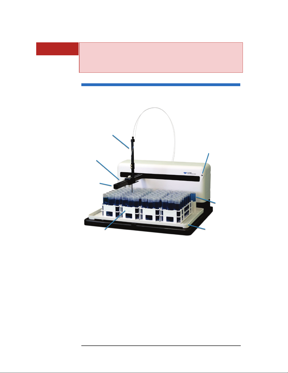
Figure 1-1 ASX-560 Autosampler—Front View
The following components are located on the front of the autosampler and are
shipped with the autosampler (see Figure 1-1).
Sample Tray. The sample tray holds the rinse station, sample racks, and
standards vials in place. The tray also contains small spills.
Sample Vial Racks. The ASX-560 includes four sample vial racks; the ASX-
280 includes two racks. You can choose from different rack sizes (common
sizes fit 21, 24, 40, 60 or 90 vials per rack). You can combine racks of
different sizes as long as the host computer’s software accepts the
combination.
Standards Vials. Ten standards vials are included with the autosampler.
The standards vials, which fit into the standards positions at the back of
the sample tray, are 50-milliliter conical centrifuge vials with caps.
Rinse Station. The flowing rinse station is located at the left end of the
standards positions at the back of the sample base. It comes with tubing
8
ASX-560 / ASX-280 Autosampler Operator’s Manual
9
Power Switch
Serial Ports
USB Port
Power Connector
Z-Drive Motor
Peristaltic Pump
Chapter 1: Introduction
used to connect the rinse station to the rinse source and the waste
container.
Arm. The arm moves the sample probe horizontally.
Z-Drive. The Z-drive moves the sample probe vertically. The Z-drive
assembly includes a Y-axis slider block and guide plate as well as the
sample probe. The Z-drive attaches onto the autosampler arm.
Power Indicator Lamp. The LED indicates that the autosampler is
connected to a power source and turned on.
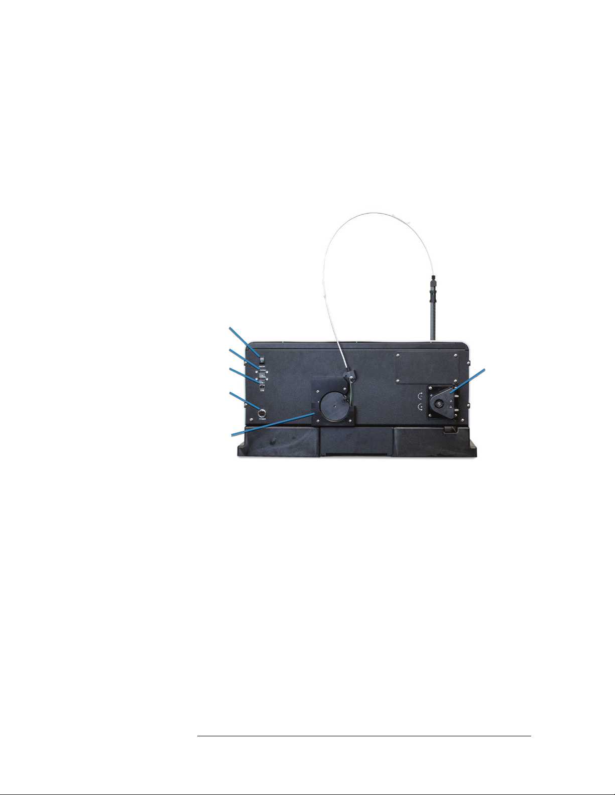
Figure 1-2 ASX-560 Autosampler—Back View
The following components are located on the back of the autosampler and are
shipped with the autosampler.
On-board peristaltic pump. A two-channel peristaltic pump moves the
rinse solution from the rinse source through the flowing rinse station.
Serial Ports. The COM1 port connects the autosampler with the analytical
instrument’s host computer. The COM2 port connects the autosampler to
other external devices, such as an autodilutor.
USB Port. The USB port can be used to interface the autosampler with the
host computer.
The following standard components are also shipped with the autosampler:
Power Supply. A desktop "brick" transformer powers the autosampler.
Sample Probe Kit. The kit includes the sample probe. The sample probe
fits into the Z-drive.
Communication Cables. The contents of the kit depend on the version of
the autosampler. Most kits include a 1.828-meter serial cable and a USB
cable.

ASX-560 / ASX-280 Autosampler Operator’s Manual
Chapter 1: Introduction
CD. The CD contains, if applicable:
Utility software
USB device drivers
Manuals
Other application-specific information
Supplied components depend on the application and the exact version of the
autosampler. See the packing list in the shipping container to see exactly which
components are supplied.
Additional Equipment Required
In addition to the provided equipment, you will need:
A host computer which has been configured with the control software for
your instrument. This computer must have an additional free USB or serial
port beyond the ports required to control the instrument and other system
components.
10

ASX-560 / ASX-280 Autosampler Operator’s Manual
11
Chapter 1: Introduction
Optional Accessories
You may need optional accessories in addition to the standard components
included with the autosampler. See the ASX-560 / ASX-280 Autosampler Spare
Parts and Accessories Catalog for details. Available accessories include:
Sample Vials and Racks.
Sample Probes. Extra probes are available in a variety of diameters. See
table below for common probe sizes.
0.3 mm ID Black band
0.5 mm ID Blue band
0.8 mm ID Red band
0.9 mm ID Yellow band
1.0 mm ID 2 Blue bands
Table 1: Sample Probe Sizes and Color Coding
Dual Rinse Station. The dual-rinse option allows more thorough rinsing
to reduce sample contamination and carryover.
Enclosure. The enclosure protects samples from contamination and
contains and exhausts fumes.
ASXP
RESS PLUS Rapid Sample Introduction System. 6-port valve system
which enables rapid sample loading and probe wash out.
NOTE:
Contact Teledyne CETAC Technologies if you need additional accessories not
listed, need added features to integrate the autosampler into your analytical
system, or have unique requirements. Research and development of new
features and accessories for the autosampler, often inspired by customer
requests, is a continuing activity at Teledyne CETAC Technologies.

ASX-560 / ASX-280 Autosampler Operator’s Manual
Chapter 1: Introduction
Chemical Compatibility
The autosampler operates reliably under a wide variety of conditions. No
metallic components are exposed above the sample vials. The top cover and
base are made from polypropylene. The arm and Z-drive are made from carbon
fiber.
The back and frame are made from a high-strength aluminum alloy that is
treated with a RoHS-compliant chemfilm and finished with an epoxy powder
coating. Long-term exposure to aqueous acids greater than 15% may cause
discoloration or bubbling of the epoxy coating.
Internal splash shields protect against occasional exposure to corrosive
chemicals. The covers are not sealed against liquid or vapor intrusion. Longterm exposure of the internal components to corrosive materials may cause
damage.
Exposure to corrosive vapors can be minimized by using an enclosure with
airflow directed down and away from the electronic components.
Components in the sample flow path are made of polyetherimide (PEI) and
polytetrafluoroethylene (PTFE). When these inert, non-metallic materials are
used at temperatures less than 135 °C, they can withstand repeated exposure
to the following substances:
CAUT ION
WARNING
Predominantly aqueous solutions of strong acids (less than 20%)
Predominantly aqueous solutions of strong bases (less than 10%)
Common organic solvents such as acetone, alcohols, ethyl acetate,
methylethylketone (MEK), petroleum oils and derived fuels, and kerosene.
DAMAGE FROM CHEMICAL EXPOSURE
Prolonged or repeated exposure to temperatures greater than 135 °C and to the
following substances can cause failure of the flow path components:
• Solutions of concentrated acids (greater than 40%).
• Solutions of concentrated bases (greater than 10% potassium, ammonium, or
sodium hydroxides).
• Partially halogenated hydrocarbons or extremely aggressive organic solvents
(chloroform, methylene dichloride, 1,1,2-trichloroethane).
Prolonged exposure to carbon tetrachloride can damage the autosampler.
CHEMICAL HAZARD
Do not use the autosampler with substances which could pose a hazard of
serious injury to the operator if spilled or injected, such as biological
substances or formic acid.
12

ASX-560 / ASX-280 Autosampler Operator’s Manual
13
Chapter 1: Introduction
Where to Go for More Information
In addition to this manual, you can refer to the following resources:
New versions of this manual may be available under “Support” on CETAC’s
Web site:
www.cetac.com
ASX-560 / ASX-280 Autosampler Spare Parts and Accessories Catalog,
available on the CETAC Web site.
CETAC Autosampler Safety Guide provides basic safety-related information
in a variety of languages.
Online help within the ASX Dashboard software.
Tel e d y ne C E TAC Te c h no l o gi e s Customer Service and Support:
Phone: 1 (800) 369-2822 (USA only)
1 (402) 733-2829
Fax: 1 (402) 733-1932
E-mail: custserv@cetac.com
The software manual for the instrument you are using.

ASX-560 / ASX-280 Autosampler Operator’s Manual
Chapter 1: Introduction
This page is intentionally blank.
14

15
2 Preparing for
Installation
Installing the autosampler requires preparation. Before you install the
autosampler, you should evaluate the physical arrangement of the laboratory
to choose a suitable location.
Choosing a Location
For the system to function optimally, the location you select must meet specific
requirements.
Space Requirements
Most analytical applications benefit from using the shortest sample flow path.
Therefore, you should place the autosampler in close proximity to the
analytical instrument. The recommended footprint for the autosampler is
shown in the following tables.
Height 28 cm (14")
without Z-Drive
Width 58 cm (232.5)
Depth 55 cm (21.6") 59 cm (23.5")
Weight 11.7 kg (26 lbs) without racks or vials
Table 2: Physical Characteristics – ASX-560
62 cm (24.4")
with Z-drive and tubing
with cables and tubing

ASX-560 / ASX-280 Autosampler Operator’s Manual
Chapter 2: Preparing for Installation
Height 28 cm (14")
without Z-Drive
Width 36 cm (14.0”)
Depth 54 cm (21.0") 58 cm (22.8")
Weight 8.1 kg (17.8 lbs) without racks or vials
Table 3: Physical Characteristics – ASX-280
The weight shown is that of the autosampler itself, without the desktop power
supply, tray, vials, sample probe, or tubing.
Allow at least 5 cm behind the autosampler for cable egress and access to the
power switch. Always position the equipment so that it is easy to disconnect
the power cord.
66 cm (26")
with Z-drive and tubing
with cables and tubing
Work Surface Requirements
The autosampler must be placed on a sturdy countertop or table. Do not place
the autosampler on a wheeled cart or folding table.
During operation, the autosampler produces both vertical and horizontal
forces. If the work surface is allowed to shake or wobble, the autosampler may
“walk” across the surface, liquids may spill, or data quality may be affected.
CAUT ION
WARNING
Rinse Solution Requirements
For most applications, deionized water or kerosene is used as the rinse agent.
Place the rinse agent source within two meters of the autosampler.
Liquid Waste Routing Requirements
Ensure that there is a liquid waste receptacle within two meters of the
autosampler. The waste receptacle inlet should be 30 to 60 centimeters lower
than the autosampler rinse station outlet and set up so that the rinse drain
tubing drops directly into the waste receptacle with no coiling and without
being submerged below the liquid level of the waste receptacle.
SUBMERGED DRAIN TUBING MAY CAUSE EQUIPMENT DAMAGE
Ensure that the rinse drain tubing is not submerged in the waste liquid. If the
tubing is submerged, waste liquid can back up in the rinse station, flooding the
sample tray.
Power Requirements
The autosampler is powered by the supplied external desktop "brick" power
supply. Place the autosampler within 1.2 meters of a power outlet.
SHOCK AND FIRE HAZARD
Use only the provided power supply. The power supply must be plugged
into an outlet which has a protective ground connection.
The autosampler is intended to operate from DC power supplied through the
provided power supply. The power supply is provided power through an AC
16
ASX-560 / ASX-280 Autosampler Operator’s Manual
17
Chapter 2: Preparing for Installation
power source that will not apply more than 240 VAC between the supply
conductors and ground. A protective ground connection by way of the
grounding connector in the power cord is required for safe operation.
Ensure that you position the autosampler so that the location where the power
supply cord plugs into it is easily accessible (is not blocked) so that it can be
quickly disconnected if needed. In case of hazard, the autosampler should be
disconnected from the power source.
The power supply socket is on the back of the autosampler below the power
switch. Connect the power supply to the autosampler first and then connect a
line cord to the power supply. Do not apply power to the power supply until
ready to operate the autosampler.
Unpacking the Autosampler
Inspect external packaging upon receipt for signs of shipping damage. Inspect
all items during unpacking and notify the carrier immediately of any concealed
damage. Check for kinked or bent tubing.
If the system is shipped or removed from storage during cold weather, allow
the packaged equipment to equilibrate to room temperature before opening
and exposing to warm, humid air. It is usually sufficient to provide four to eight
hours for this purpose.
CAUT ION
EQUIPMENT DAMAGE FROM CONDENSATION
If condensation forms on or inside the autosampler, allow it to dry thoroughly
before connecting it to a power source and operating it. Failure to do so may cause
equipment damage.
Remove the packing checklist from the shipping container, and check off items
against it. Leave accessories in the packing until you are ready to install them.
NOTE
Keep the factory packaging for use in case the product ever needs to be
returned or shipped to another location.

ASX-560 / ASX-280 Autosampler Operator’s Manual
Chapter 2: Preparing for Installation
This page is intentionally blank.
18

19
3 Installing the
Autosampler
The autosampler can be installed with minimal effort; no tools are required.
You can remove thumbscrews with tools if necessary, but do not tighten them
with anything other than your fingers.
To install the autosampler, you must complete the following tasks. Each of
these tasks will be discussed in detail later in this chapter.
Mount the Z-drive.
Connect the rinse station.
Assemble the sample vial racks.
Connect the sample tubing to the analytical instrument.
Connect the autosampler to the power supply and to the host computer.
WARNING
PINCH/PUNCTURE HAZARD
Ensure the power switch is off and the power cord is unplugged before
proceeding with installation. If the power is left on, motors may move
unexpectedly and cause injury.
ASX-560 / ASX-280 Autosampler Operator’s Manual
Chapter 3: Installing the Autosampler
Mounting the Tray and Rinse Station
1
Place the tray on the base of the autosampler.
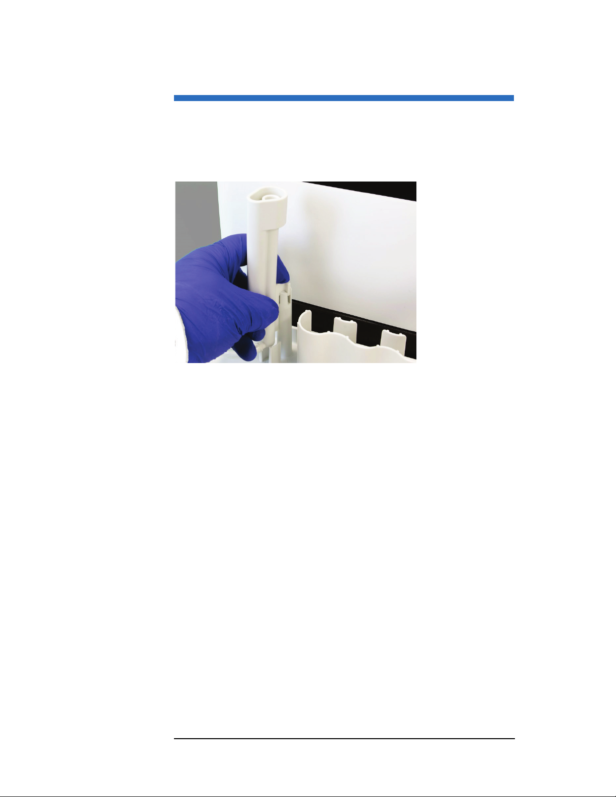
2 Place the rinse station on the post on the back left corner of the tray. Press
straight down until it is fully seated.
Figure 3-1 Mounting the Rinse Station
20
ASX-560 / ASX-280 Autosampler Operator’s Manual
21
Chapter 3: Installing the Autosampler
Mounting the Z-Drive
The Z-drive moves the probe up and down. The Z-drive is shipped detached
from the autosampler.
Attaching the Z-Drive to the Autosampler Arm
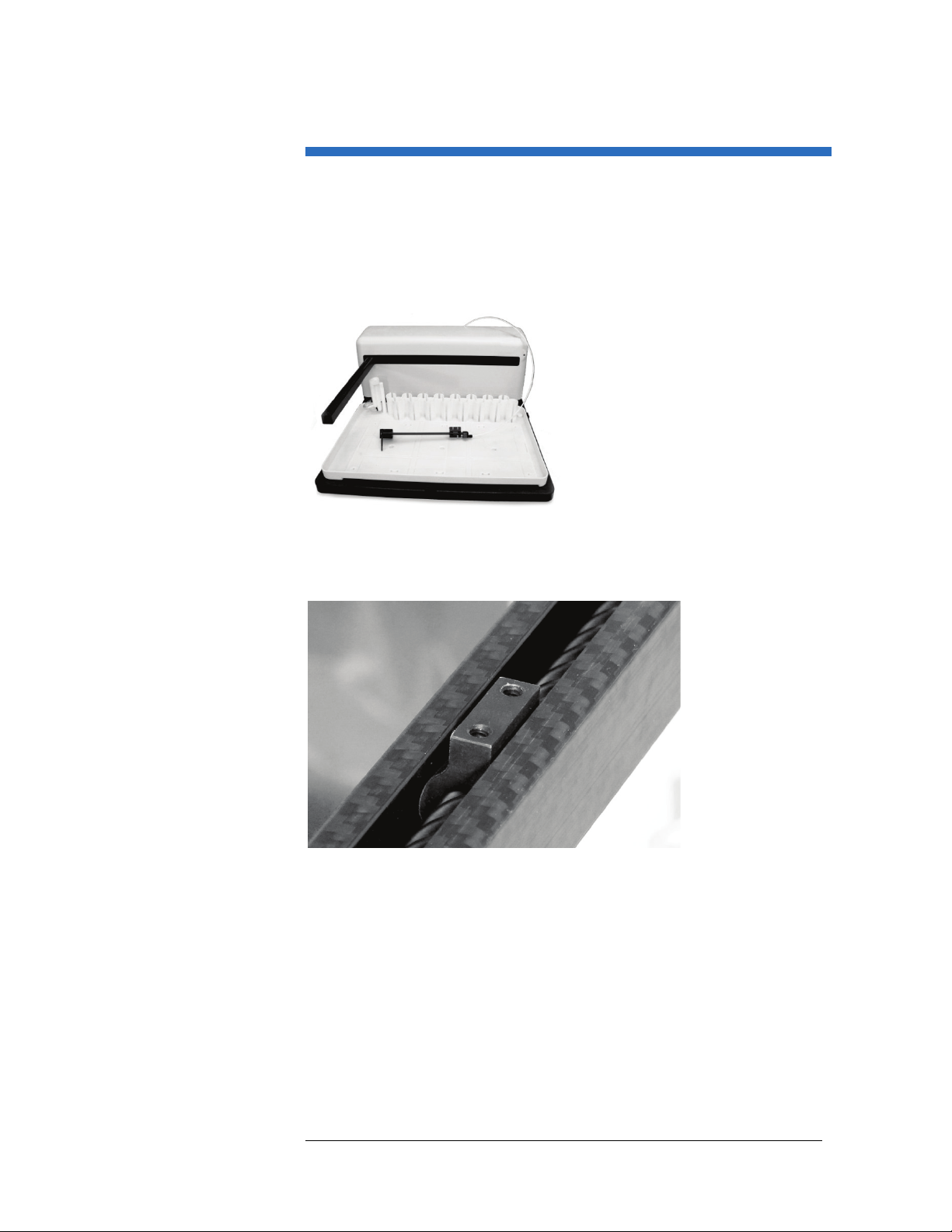
1 Carefully remove any packaging materials from the Z-drive.
Figure 3-2 Z-Drive Before Installation
2 Find the Y-axis carriage on the arm of the autosampler. The Z-drive will be
attached to this carriage.
Figure 3-3 Y-Axis Carriage
ASX-560 / ASX-280 Autosampler Operator’s Manual
Chapter 3: Installing the Autosampler
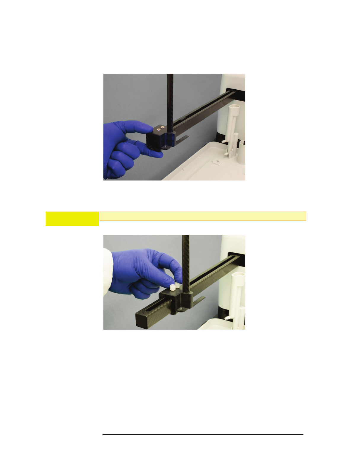
3 Slide the Z-drive onto the y-arm until the two holes in the Y-axis slider block
align with the matching holes in the Y-axis carriage.
Figure 3-4 Sliding the Z-Drive Onto the Arm
CAUT ION
4 Secure the Z-drive to the carriage using the two thumbscrews.
Do not tighten the thumbscrews with anything other than your fingers.
Figure 3-5 Securing Z-Drive Onto the Arm
22
ASX-560 / ASX-280 Autosampler Operator’s Manual
23
Chapter 3: Installing the Autosampler
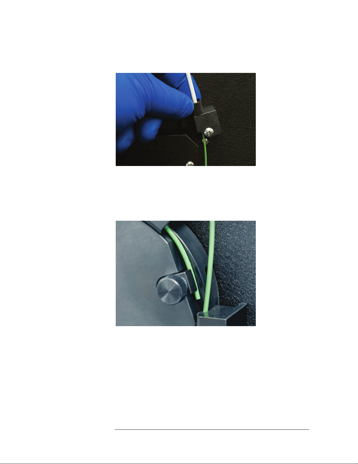
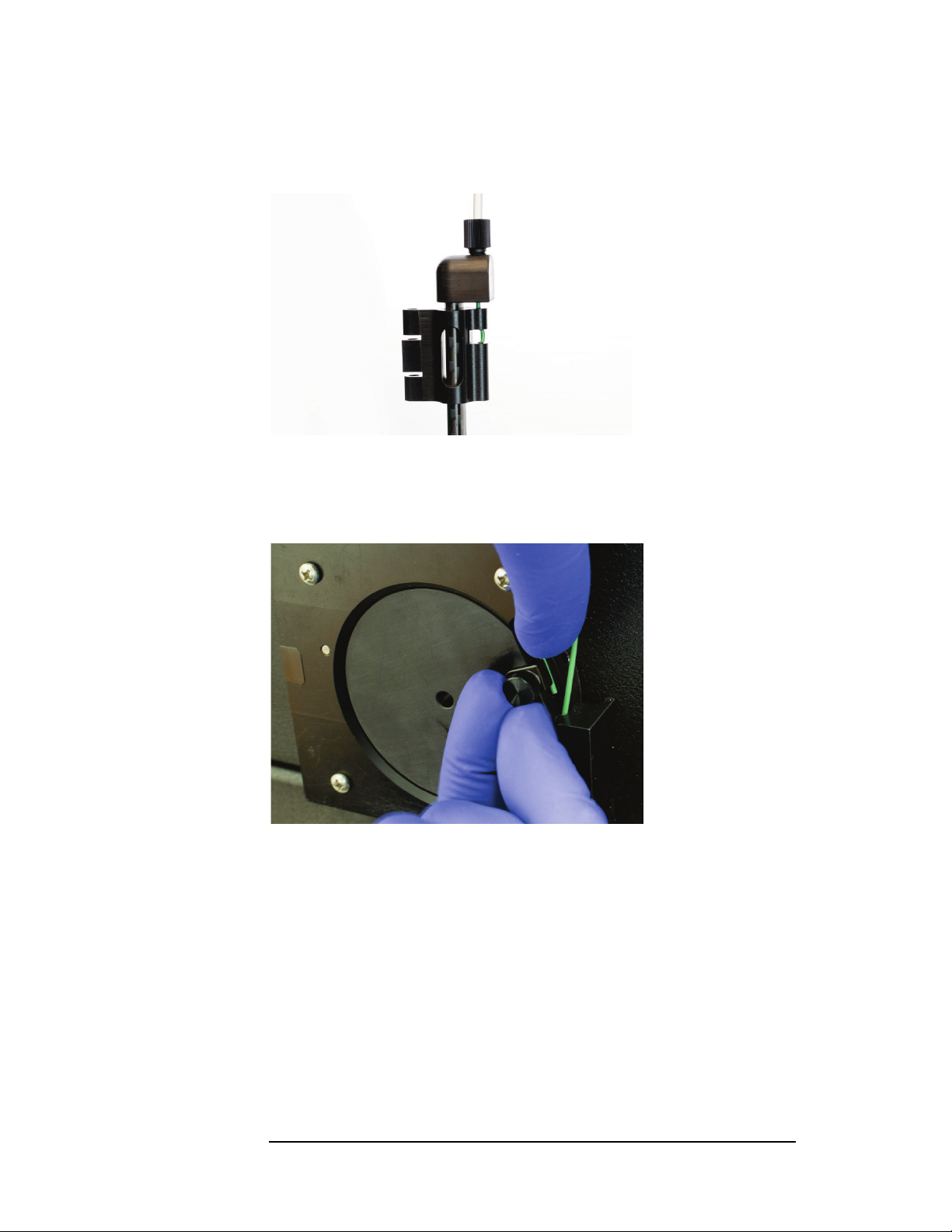
5 Feed the cable through the rear guide block and around the rotor, then tighten
the nut to secure the cable sleeve to the guide block.
Figure 3-6 Guide Block with Nut
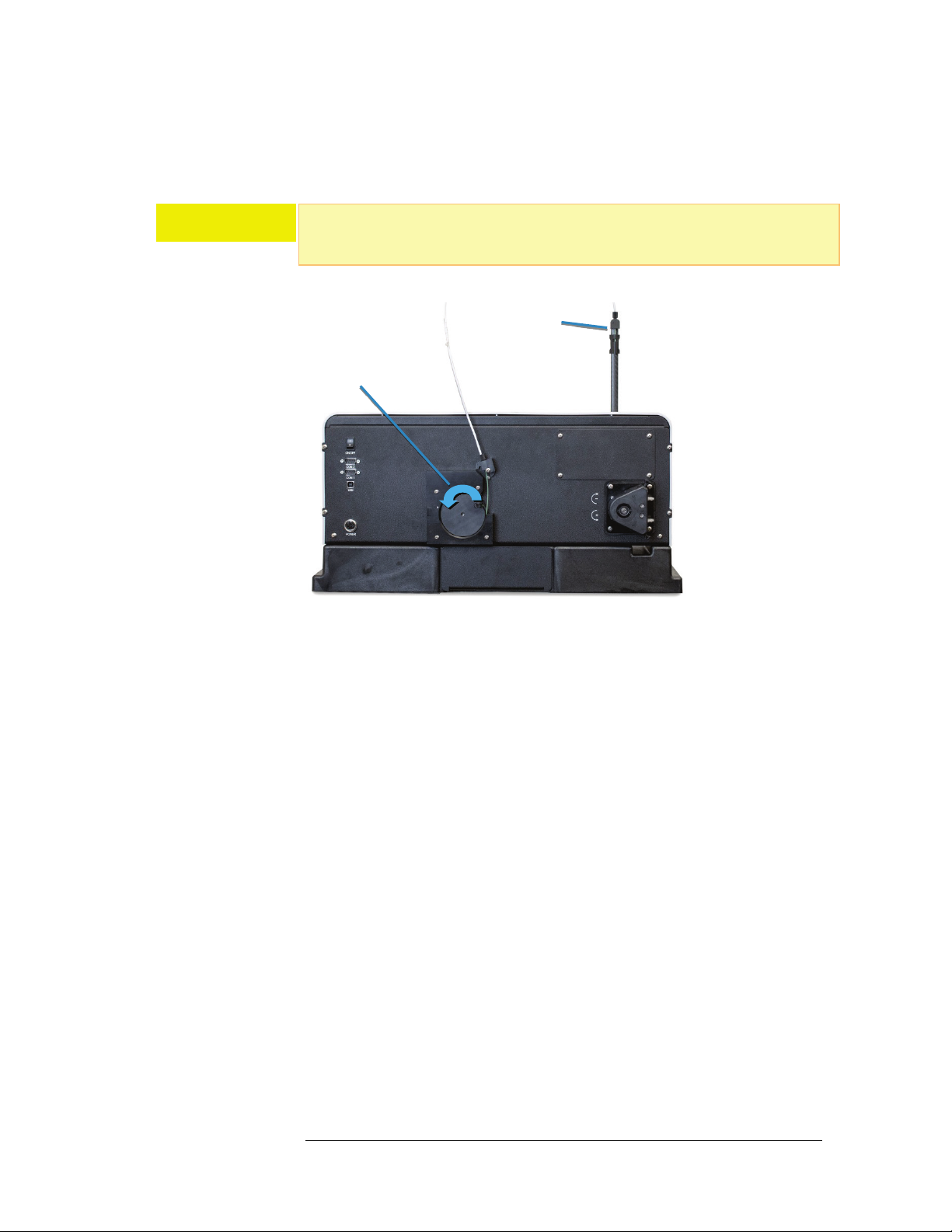
6 Turn the rotor clockwise as far as it will go.
7 Finish sliding the cable around the rotor on the back of the autosampler.
Loosen the thumbscrew on the rotor to allow the cable to pass through the
clamp, with about 2 mm of cable extending past the clamp.
Figure 3-7 Position of Cable on Rotor
ASX-560 / ASX-280 Autosampler Operator’s Manual
Chapter 3: Installing the Autosampler
8 Verify that there is a small gap between the Z-axis slider and cap at the top of
the Z-drive (approximately 1-3 mm). Adjust the cable a bit if necessary.
Figure 3-8 Z-Drive at Top Position With Gap
9 Hold the cable flat against the rotor and secure the cable by tightening
thumbscrew on the rotor. The thumbscrew should be as tight as possible using
just your fingers.
Figure 3-9 Securing Cable to Rotor
The cable is pre-cut to the proper length and does not need to be trimmed
when properly installed.
24
ASX-560 / ASX-280 Autosampler Operator’s Manual
25
Rotate to Move the
Drive
Z-Axis Slider
Chapter 3: Installing the Autosampler
10 Rotate the Z-drive rotor back and forth to ensure that the Z-drive moves up
and down freely.
CAUT ION
Never push the Z-axis slider to move it up or down. Pushing on the Z-axis slider can
kink the drive cable. Instead, rotate the Z-drive rotor on the back of the
autosampler.
Z-
Figure 3-10 Z-Drive Rotor
If the rotor does not rotate freely, STOP and reinstall the drive cable (see
"Replacing the Z-Drive" on page 75).

ASX-560 / ASX-280 Autosampler Operator’s Manual
Chapter 3: Installing the Autosampler
Connecting the Rinse Station
The rinse station is mounted to the tray of the autosampler, at the left end of
the standards rack.
Typically, deionized water, an acid rinse such as a 2% HNO
, or a solution from
3
the kerosene family, is used as the rinse solution.
The rinse solution flows from the sample probe reservoir to the drain (rinse
out) reservoir within the rinse station. The waste rinse solution is then drained
from the rinse station.
The inlet of the rinse station is at the bottom of the rinse station. The rinse
solution flows from the bottom to the top of the sample probe reservoir. Upflow rinsing is the most effective method for decontaminating the sample
probe tube between samples. Reversing the connections will reverse the flow
direction, resulting in cross-contamination and unsatisfactory performance.
Waste Rinse Solution
In most cases, rinse solution will be “recycled” by returning it to the rinse
solution bottle. If necessary, rinse solution can be pulled from a fresh bottle
and used solution drained to a waste container. Remember to label the waste
container according to your laboratory policy and local regulations.
Ensure that the tubing outlet is placed so that it will remain above the surface
of the liquid in the waste container. If the end of the tube is immersed, the
waste solution might back up and overflow.
Tubing Considerations
Verify that the supplied tubing material is compatible with the rinse solution
you are using. There are many different types of tubing that can be used for the
rinse station. Clear Tygon
(yellow), and PharMed
depending on the application and user preference. Clear Superthane
can used everywhere other than the pump tubing. Contact CETAC if you need
different tubing material.
The fittings on the rinse station use
fittings on the peristaltic pump use smaller ⅛ inch (3.2 mm) ID tubing. If
tubing needs to be replaced, a tubing kit with a adapter fittings can be ordered
from CETAC.
®
tubing is provided. Viton®, Tygon® Fuel and Lube
®
(opaque) may also be used for pump tubing
3
/16 inch (4.8 mm) ID tubing, but the
®
tubing
Carefully press the tubing straight on to the fittings to avoid breaking the
fittings. If you find it difficult to get a good connection to the rinse station,
remove the rinse station and press the tubing firmly so that it completely
covers the barb of the fitting. It helps to use your other hand to apply counterpressure.
26
ASX-560 / ASX-280 Autosampler Operator’s Manual
27
Chapter 3: Installing the Autosampler
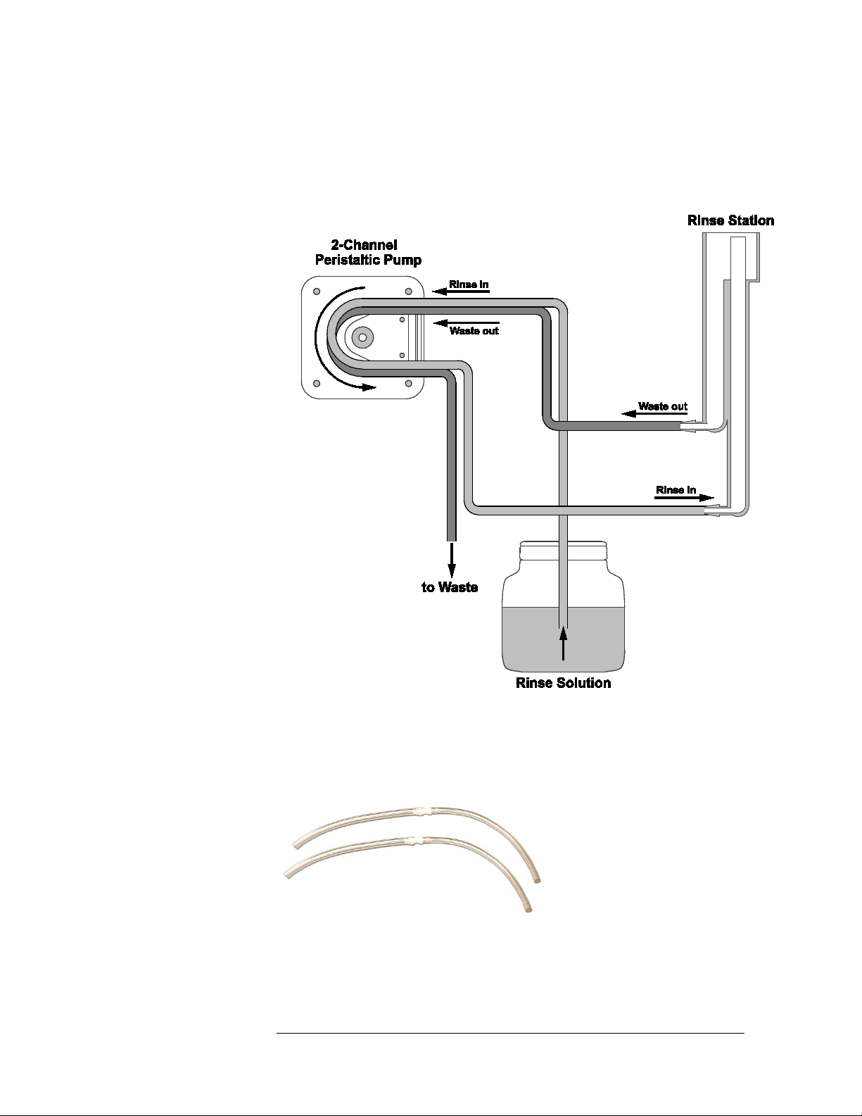
Pumped Drain Arrangement
In a pumped drain arrangement, one channel of the peristaltic pump to supply
rinse solution to the rinse station, while the other channel of the pump drains
the used rinse solution.
Figure 3-11 Typical Pumped Drain Arrangement
To connect the rinse station using the pumped drain, complete the following
steps:
1 Locate the two pieces of adapter tubing.
Figure 3-12 Adapter Tubing
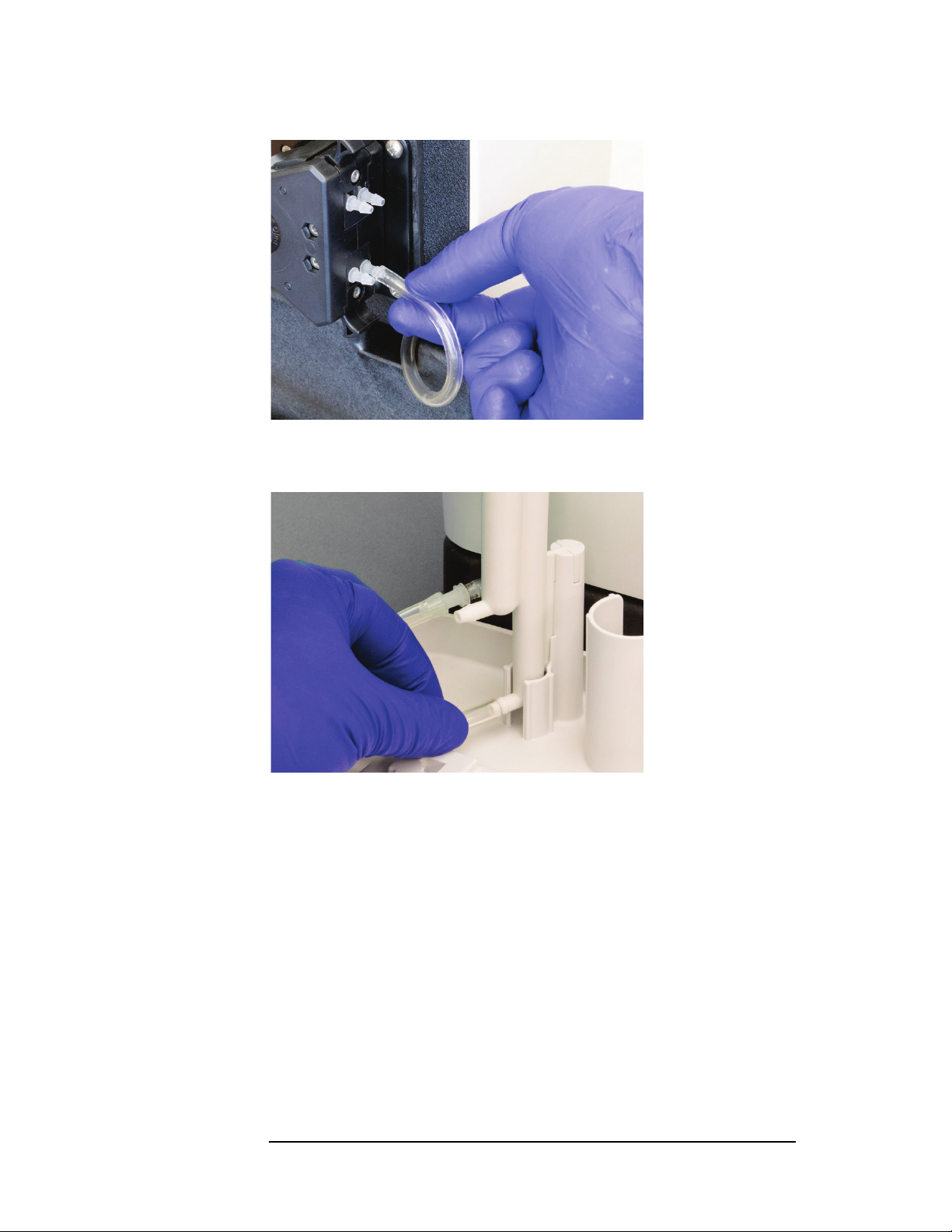
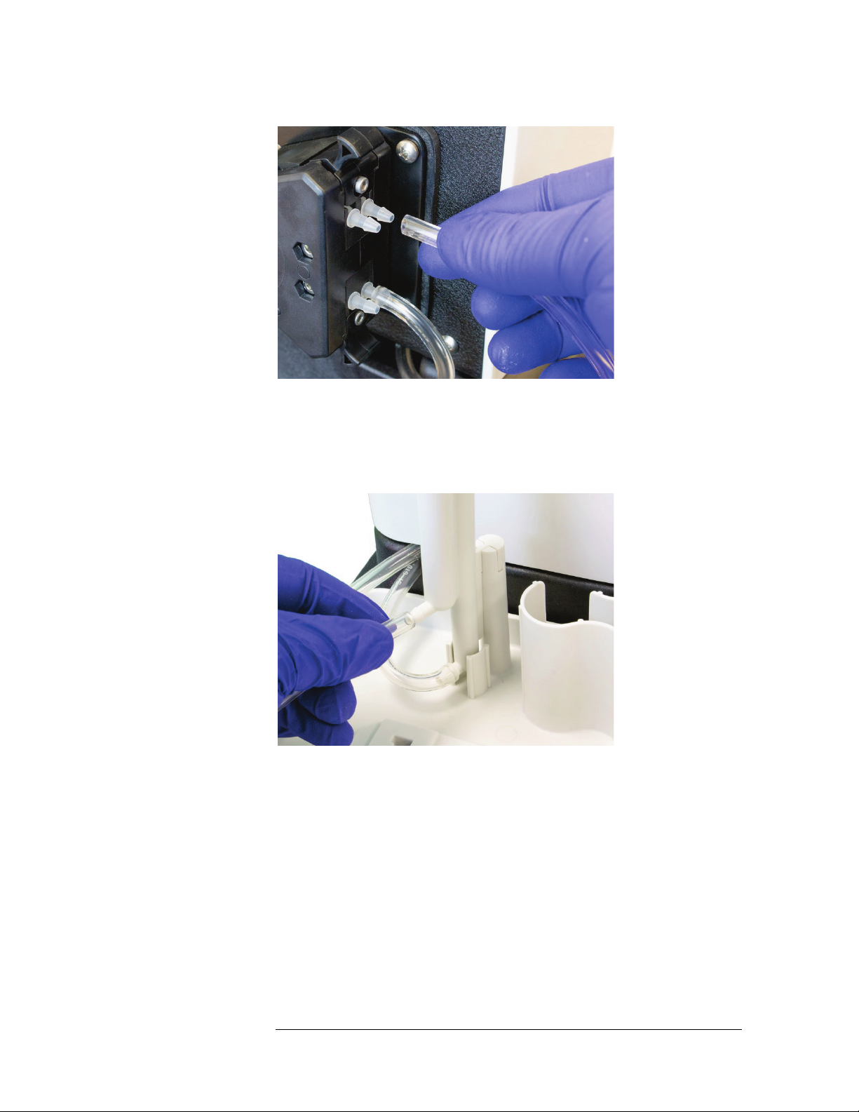
2 Connect the smaller end of one of the pieces of adapter tubing to the fitting at
the bottom of the pump, closest to the back of the autosampler.
ASX-560 / ASX-280 Autosampler Operator’s Manual
Chapter 3: Installing the Autosampler
Figure 3-13 Connecting the Pump Output
3 Connect the larger end of the tubing to the bottom fitting of the rinse station.
Figure 3-14 Connecting the Rinse Station Input
4 Find the pump channel which is connected to the rinse station. Use an
appropriate length of the smaller ⅛ inch (3.2 mm) ID tubing to connect the
rinse solution source to the fitting at the top of this channel.
28
ASX-560 / ASX-280 Autosampler Operator’s Manual
29
Chapter 3: Installing the Autosampler
Figure 3-15 Connecting the Rinse Solution Input
5 Locate the other piece of adapter tubing.
6 Connect the larger end of the adapter tubing to the outlet fitting of the rinse
station.
Figure 3-16 Connecting the Rinse Station Drain
7 Connect the smaller end of the adapter tubing to the input of the second pump
channel.

ASX-560 / ASX-280 Autosampler Operator’s Manual
Chapter 3: Installing the Autosampler
Figure 3-17 Connecting the Rinse Station Drain to the Pump Input
8 Connect up to 1.8 meters of the larger
3
/16 inch (4.8 mm) ID tubing between the
outlet fitting of the pump and the waste container.
Figure 3-18 Connecting the Rinse Station Drain
Ensure that the tubing outlet is placed so that it will remain above the surface
of the liquid in the waste container. If the end of the tube is immersed, the
waste solution might back up and overflow.
30
 Loading...