

Page 1

Copyright 2011-2016
07406B DCN7347
Teledyne API
29 September 2016
Manual Addendum
Models T320 and T320U
N2O Analyzers
(Addendum to T300/T300M Manual, PN 06864)
© TELEDYNE API (TAPI)
9970 CARROLL CANYON ROAD
SAN DIEGO, CA 92131-1106
USA
Toll-free Phone: 800-324-5190
Phone: +1 858-657-9800
Fax: +1 858-657-9816
Email: api-sales@teledyne.com
Website: http://www.teledyne-api.com/
Page 2

Page 3
should only be used for the purpose and in the manner described in
in a manner other than that for which it was
intended, unpredictable behavior could ensue with possible hazardous
SAFETY MESSAGES
Important safety messages are provided throughout this manual. Please read these messages carefully.
A safety message alerts you to potential hazards that could hurt you or others. Each safety message is
associated with a safety alert symbol. These symbols are found in the manual and inside the instrument. The
definition of these symbols is described below:
WARNING: Electrical Shock Hazard
HAZARD: Strong oxidizer
GENERAL WARNING/CAUTION: Read the accompanying
message for s pecifi c i nformation.
CAUTION : Hot Surface Warning
Technician Symbol: All operations marked with this symbol are to
be performed by qualified maintenance personnel only.
DO NOT TOUCH: Touching some parts of the instrument without
protection or proper tools could result in damage to t he part(s)
and/or the instrument.
Electrical Ground: This symbol inside the instrument marks the
central safety grounding point for the instrument.
CAUTION - General Safety Hazard
This instrument
this manual. If you use this instrument
consequences.
NEVER use any gas analyzer to sample combustible gas(es).
Note
Technical Assistance r egarding the use and maintenan ce of the T320/T320U or any other Teledyne API
product can be obtained by contacting Teledyne API’s Technical Support Department:
Phone: 800-324-5190
Email: sda_techsupport@teledyne.com
or by accessing various service options on o ur website at http://www.teledyne-api.com/.
07406B DCN7347 i
Page 4
AVERTISSEMENT : Risque de choc électrique
DANGER : Oxydant puissant
AVERTISSEMENT GÉNÉRAL / MISE EN GARDE : Lire la consigne
MISE EN GARDE : Surface chaude
Ne pas toucher : Toucher à certaines parties de l’instrument sans protection ou
Pictogramme « technicien » : Toutes les opérations portant ce symbole doivent
Mise à la terre : Ce symbole à l’intérieur de l’instrument détermine le point central
MISE EN GARDE
CONSIGNES DE SÉCURITÉ
Des consignes de sécurité importantes sont fournies tout au long du présent manuel dans le but d’éviter des
blessures corporelles ou d’endommager les instruments. Veuillez lire attentivement ces consignes. Chaque
consigne de sécurité est représentée par un pictogramme d’alerte de sécurité; ces pictogrammes se retrouvent
dans ce manuel et à l’intérieur des instruments. Les symboles correspondent aux consignes suivantes:
complémentaire pour des renseignements spécifiques
sans les outils appropriés pourrait entraîner des dommages aux pièces ou à
l’instrument.
être effectuées uniquement par du personnel de maintenance qualifié.
de la mise à la terre sécuritaire de l’instrument.
Cet instrument doit être utilisé aux fins décrites et de la manière décrite dans ce
manuel. Si vous utilisez cet instrument d’une autre manière que celle pour laquelle il
a été prévu, l’instrument pourrait se comporter de façon imprévisible et entraîner des
conséquences dangereuses.
NE JAMAIS utiliser un analyseur de gaz pour échantillonner des gaz combustibles!
ii 07406B DCN7347
Page 5

TABLE OF CONTENTS
1. INTRODUCTION ..................................................................................................................................................................... 5
2. SPECIFICATIONS, APPROVALS AND WARRANTY ........................................................................................................... 7
2.1. Specifications ................................................................................................................................................................... 7
2.2. EPA Equivalency Designation .......................................................................................................................................... 8
2.3. CE Mark Compliance ....................................................................................................................................................... 8
2.4. Warranty ........................................................................................................................................................................... 8
3. GETTING STARTED .............................................................................................................................................................. 9
3.1. Unpacking the T320/T320U .............................................................................................................................................. 9
3.2. Initial Operation of the T320/T320U ................................................................................................................................. 9
3.3. Functional Check .............................................................................................................................................................. 9
3.4. Initial Calibration ............................................................................................................................................................. 10
3.4.1. Calibration Gases ................................................................................................................................................... 10
3.4.2. Internal Pneumatic Flow ......................................................................................................................................... 11
3.4.3. Pneumatic Connections to T320/T320U Basic Configuration: ................................................................................ 12
3.4.4. Pneumatic Connections to T320/T320U with Internal Valve Options Installed ....................................................... 13
3.4.5. Pneumatic Connections to T320/T320U in Multipoint Calibration Applications ....................................................... 14
4. FREQUENTLY ASKED QUESTIONS & GLOSSARY .......................................................................................................... 15
5. OPTIO NAL HARDWARE AND SOFTWARE ....................................................................................................................... 17
5.1. Calibration Valve Options for the T320/T320U ............................................................................................................... 17
5.1.1. Zero/Span with common Shutoff valves (Option 50G) ............................................................................................ 18
6. BASIC OPERATION ............................................................................................................................................................. 19
6.1. Test Functions ................................................................................................................................................................ 19
6.1.1. Selecting a Test Channel Function for Output A4 ................................................................................................... 20
7. ADVANCED FEATURES ...................................................................................................................................................... 21
8. REMOTE OPERATION ......................................................................................................................................................... 23
8.1.1. Hessen Protocol ..................................................................................................................................................... 23
9. CALIBRATION PROCEDURES ........................................................................................................................................... 25
10. EPA PROTOCOL CALIBRATION ..................................................................................................................................... 27
11. PRINCIPLES OF OPERATION .......................................................................................................................................... 29
12. MAINTENANCE SCHEDULE ............................................................................................................................................. 31
13. TROUBLESHOOTING & SERVICE ................................................................................................................................... 33
LIST OF FIGURES
Figure 3-1. T320 Pneumatic Flow ............................................................................................................................11
Figure 3-2. T320U Pneumatic Flow ..........................................................................................................................11
Figure 3-2. Pneumatic Connections, Basic Configuration Using Gas Dilution Calibrator ........................................12
Figure 3-3. Pneumatic Connections, Basic Configuration Using Bottled Span Gas ................................................12
Figure 3-4. Pneumatics: Option Z/S Valve w ith Shutoff Valve for Pressurized Span and Atmospheric Zero..........13
Figure 3-5. Pneumatics: Option Z/S without Shutoff Valve ......................................................................................13
Figure 3-6. Pneumatics: Option Z/S Valve with Common Shutoff Valve for Pressurized Zero and Span ...............14
Figure 5-1. Internal Pneumatic Flow, Option Zero/Span with Common Shutoff Valves ..........................................18
LIST OF TABLES
Table 2-1. T320/T320U Basic Unit Specifications ...................................................................................................... 7
Table 5-1. T320/T320U Available Valve Options .....................................................................................................17
Table 5-2. Zero/Span/Shutoff Valve Operating States for Option 50G ....................................................................18
Table 6-1. Test Functions Defined ...........................................................................................................................19
Table 6-2. Test Channels Functions Available on the T320/T320U’s Analog Output ..............................................20
07406B DCN7347 iii
Page 6

TABLE OF CONTENTS Teledyne API T320/T320U Addendum to T300/T300M Manual
LIST OF APPENDICES
APPENDIX A – MENU TREES and SOFTWARE DOCUMENTATION
APPENDIX B –SPARE PARTS LIST
APPENDIX C - REPAIR QUESTIONNAIRE
APPENDIX D - SCHEMATICS
iv 07406B DCN7347
Page 7

1. INTRODUCTION
The T320 and T320U are Gas Filter Correlation (GFC) analyzers that are designed to measure low level and
trace level nitrous oxide (N
operating range; 1000 ppm for the T320 and 200 ppm for the T320U. The T320 and T320U are designed to be
used for monitoring background levels of N
contamination of bottled gases.
This addendum is a supplement to the T300/T300M manual (P/N 06864) to facilitate setup, operation,
calibration, troubleshooting and repair of T320 and T320U nitrous oxide (N
up information, operating ins tr uctions as well as maintenance, troubleshooting and repair methods are the same
for the T320/T320U and can be found in the T300/T300M manual (P/N 06864). The T320 is very similar to the
T300M, and the T320U is very similar to the T300:
When using the T300/T300M manual, it is necessary to substitute the words nitrous oxide for carbon monoxide
and the chemical abbreviation N
O), respectively. The primary difference between the models is their maximum
2
O in the atmosphere, byproducts of combustion products and
2
O) analyzers. Most of the basic set
2
T320 = T300M T320U = T300
O for CO:
2
Carbon Monoxide
→ Nitrous Oxide CO → N
O
2
There are six major differences between the T320/T320U and their counterpart models, T300M/T300:
• Operating wavelength: A different photo detector is used that closely matches the peak absorption
wavelength of N
• Gas Filter Correlation Filter (GFC) wheel: The GFC wheel is filled with N
correlate properly with N
2
O.
2
O.
O rather than CO to
2
• Software: Display text strings, variable names and variable values reflect the difference in gas name
and physical characteristic. Wherever “CO” is displayed on the T300/T300M “N2O” will be displayed on
the T320/T320U.
• Calibration Methods: There are no specialized USEPA calibration methods since these methods
currently do not exist.
• Calibration Gases: Since there are no readily available low cost N
generators like the TAPI model 701, whic h do not remove N
O, zero gas must be either N2 or synthetic
2
O scrubbers and traditional zero air
2
air - especially for the T320U.
• Calibration Valve Options: Due to there being no N
O scrubbers or traditional zero air generators for
2
either the T320 or the T320U, Options 51B and 51C for the T300M and T300 are not available for the
T320 or T320U.
NOTE
The information contained in this addendum is relevant to T320/T320U analyzers, some of which may
not be applicable to the current version of software.
07406B DCN7347 5
Page 8

Introduction Teledyne API T320/T320U Addendum to T300/T300M Manual
This page intentionally left blank.
6 07406B DCN7347
Page 9

1,2
1, 2, 3
1,2
1 Ethernet: 10/100Base-T
4 analog outputs
1 USB com port
3 4-20mA current outputs
2. SPECIFICATIONS, APPROVALS AND WARRANTY
This section provides the specifications for the T320 and the T320U analyzers, and references approvals and
warranty.
2.1. SPECIFICATIONS
Specifications differ between the T320 and the T320U analyzers for Ranges, Noise, Lower Detectable Limit and
Drift.
Table 2-1. T320/T320U Basic Unit Specifications
Parameter Model T320 Model T320U
Min: 0-1 ppm Full scale 0-200 ppb Full scale
Ranges
Measurement Units ppb, ppm, µg/m3, mg/m3 (selectable)
Zero Noise
Span Noise
Lower Detectable Limit
Zero Drift (24 hours) 2 < 0.1 ppm < 25 ppb
Span Drift (24 hours) 2, 4 < 0.5% of reading < 0.5% of reading
Lag Time 1 <10 sec
Rise/Fall Time 1 <60 sec to 95%
Linearity 6 1% of full scale
Precision 1, 5 0.5% reading
Sample Flow Rate 800 cm3/min. ± 10%
Voltage Coefficient < 0.05 % of reading per V
Power Requirements 100V-120V, 220V-240V, 50/60 Hz
Analog Output Ranges 10V, 5V, 1V, 0.1V (selectable)
Recorder Offset
Analog Output Resolution 1 part in 4096 of selected full-scale voltage
< 0.02 ppm (RMS) < 5 ppb (RMS)
< 0.5% of reading RMS over 8 ppm < 0.5% of reading RMS over 2 ppm
0-1000 ppm Full scale (selectable, dual
Max:
ranges and auto ranging supported)
< 0.04 ppm < 10 ppb
0-200 ppm Full scale (selectable, dual ranges
and auto ranging supported)
± 10%
Included I/O
Optional I/O
07406B DCN7347 7
2 RS-232 (300 – 115,200 baud)
2 USB device ports
8 opto-isolated digital status outputs
6 opto-isolated digital control inputs
1 RS485
8 analog inputs (0-10V, 12-bit)
4 digital alarm outputs
Multidrop RS232
Page 10

Specifications, Approvals and Warranty Teledyne API T320/T320U Addendum to T300/T300M Manual
Parameter
Model T320
Model T320U
1
Or 20 ppb, whichever is greater
4
For values greater than twice the LDL
Temperature Range
Humidity Range 0-95% RH, Non-Condensing
Dimensions (HxWxD) 7" x 17" x 23.5" (178 mm x 432 mm x 597 mm)
Weight 50 lb (22.7 kg)
Environmental Conditions Installation Category (Over voltage Category) II Pollution Degree 2
Certifications
As defined by the USEPA
2
At constant temperature and sample pressure
3
5 - 40°C operating
CE: IEC 61010-1:2001
North American: cNEMKO (Canada): CAN/CSA-C22.2 No. 61010-1-04
NEMKO-CCL (US): UL No. 61010-1 (2
Or 10 ppb, whichever is greater
5
Or LDL whichever is greater
6
nd
Edition)
2.2. EPA EQUIVALENCY DESIGNATION
There is no US EPA reference method for the measurement of nitrous oxide; therefore, neither the T320 nor the
T320U are designated as reference or equivalent methods. Hence, the EPA Protocol Calibration section of the
Model T300/T300M Operation Manual does not appl y.
2.3. CE MARK COMPLIANCE
See the CE Mark Compliance section of the T300/T300M manual (P/N 06864).
2.4. WARRANTY
See the Warranty page of the T300/T300M manual (P/N 06864).
8 07406B DCN7347
Page 11
1
These range displays appear if the
instrument’s reporting ranges are set for
either the DUAL to AUTO modes.
2
Not in “U” models.
3
Only in “U” models.
4
Only appears if analog output A4
is
actively reporting a TEST FUNCTION.
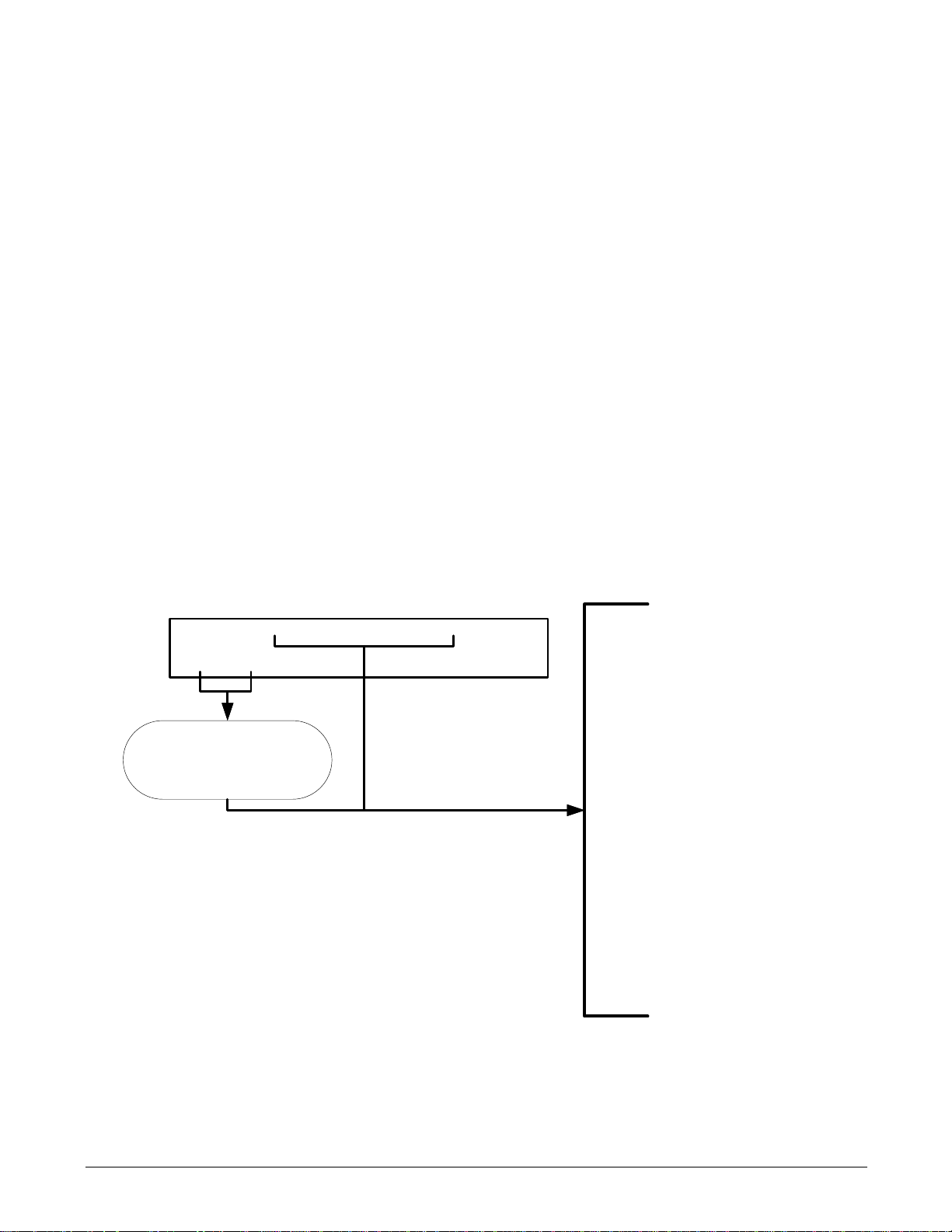
SAMPLE RANGE=50.
000 PPM N2O= XXXX
<TST TST> CAL SETUP
Toggle <TST TST> buttons
to scroll through list of
functions
·
RANGE=[Value] PPB
·
RANGE
1=[
Value] PPB
1
·
RANGE2=[Value
]
PPB
1
·
STABIL=[
Value]
PPM or PPB
·
N2O MEAS=[Value]
MV
·
N2O REF=[Value] MV
·
MR RATIO=[Value]
·
PRES
=[Value] IN-HG-A
·
SAMP FL=[Value] CC/M
·
SAMPLE TEMP=[Value]ºC
2
·
BENCH TEMP=[Value]ºC
·
WHEEL TEMP=[Value]ºC
·
OVEN TEMP=[Value
]ºC
3
·
BOX TEMP=[Value]ºC
2
·
PHT DRIVE=[Value] MV
·
SLOPE=[Value]
·
OFFSET=[Value]
·
TEST
=[Value] MV
4
·
TIME=[HH:MM:SS
]
3. GETTING STARTED
3.1. UNPACKING THE T320/T320U
Follow the unpacking directions in the Getting Started section of the T300/T300M manual (P/N 06864); note that
the Final Test and Validation Data Sheet for the T320 or the T320U are unique .
3.2. INITIAL OPERATION OF THE T320/T320U
The analyzer should be started and allowed to warm up; a functional check followed by calibration should be
performed. The process for starting and warming up the T320/T320U is identical to that described in the Initial
Operation section of the T300/T300M Operators Manual (P/N 06864).
3.3. FUNCTIONAL CHECK
The functional check information also in the Initial Operation section of the T300/T300M Operators Manual (P/N
06864) is applicable to the T320/T320U with the following exc epti on(s ) .
The Test functions available from the front panel of the T320 or T320U are:
07406B DCN7347 9
Page 12

Getting Started Teledyne API T320/T320U Addendum to T300/T300M Manual
3.4. INITIAL CALIBRATION
3.4.1. CALIBRATION GASES
The information found in the Calibration Gases section of the T300/T300M Operators Manual (P/N 06864) is
applicable to the T320/T320U with the following exceptions:
ZERO GAS
Zero gas is similar in chemical composition to the atmosphere that is to be measured but scrubbed of all
components that might affect the analyzers readings, in this case N
T320/T320U this gas MUST be synthetic air, ultra zero air or nitrogen (N
NOTE
Zero air created by a Zero Air Generator like the T-API Model T701 should not be used since the T701
does not scrub N2O. Likewise since there are no effective and convenient catalytic, absor ptive or
reactive scrubbers for N2O, T-API does not offer a zero scrubber cartridge.
O and water vapor. For the
2
).
2
SPAN GAS
Span gas is specifically mixed to match the chemical composition of the type of gas being measured at
near full scale of the desired measurement range. In this case, N
T320/T320U analyzer, it is recommended that you use a span gas with a N
80% of the measurement range for your application.
EXAMPLE: If the application is to measure between 0 ppm and 500 ppm, an appropriate span gas
concentration would be 400 ppm N
Some applications require a multipoint calibration procedure where span gases of different
concentrations are applied to the analyzer under test. We recommend using a bottle of calibrated N
gas of higher concentration in conjunction with a gas dilution calibrator such as a Teledyne Instruments
Model T700. This type of calibrator precisely mixes a high concentration gas from with zero gas (both
supplied externally as either synthetic air or N
concentration. Linearity profiles can be automated with this model and run unattended over night.
Currently there are no Standard Reference Material (SRM) N
(National Institute of Standards and Technology) therefore it is essential that span gas be purchased
from a reputable supplier and that the gas be traceable to a reputable national standards laboratory.
O in N2.
2
O measurements made with the
2
) to accurately produce span gas of the correct
2
O gases available o ff -the-shelf from NIST
2
O concentration equal to
2
O
2
10 07406B DCN7347
Page 13
Teledyne API T320/T320U Addendum to T300/T300M Manual Getting Started
INSTRUMENT CHASSIS
Flow
/ Pressure
Sensor PCA
SAMPLE
PRESSURE
SENSOR
FLOW
SENSOR
Sample Gas
Flow Control
SAMPLE GAS
INLET
EXHAUST
GAS OUTLET
Particulate Filt er
PUMP
GFC Wheel
Housing
GFC Motor Heat Sync
SAMPLE CHAMBER
INST RUM ENT CHASSIS
CO
Scrubber
Flow / Pressure
Sensor PCA
SAMPLE
PRESSURE
SENSOR
FLO W
SENSOR
Sample G as
Flow Control
SAMPLE G AS
INLET
EXHAUST
GAS OUTLET
/
PUMP
GFC Wheel
Housing
GF C Motor Heat Sync
SAMPLE CH AMBE R
Multi-Tube Nafion Dryer
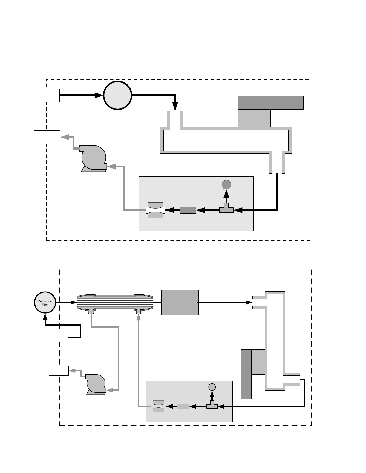
3.4.2. INTERNAL PNEUMATIC FLOW
The T320 internal pneumatic flow is illustrated in Figure 3-1.
The T320U internal pneumatic flow is illustrated in Figure 3-2.
Figure 3-1. T320 Pneumatic Flow
07406B DCN7347 11
Figure 3-2. T320U Pneumatic Flow
Page 14

Getting Started Teledyne API T320/T320U Addendum to T300/T300M Manual
Source of
SAMPLE GAS
Removed during
calibration
VENT
Calibrated N2O
Gas
at 100x span gas
concentration
VENT
here if input
is pressurized
Chassis
PRESSURE SPAN
IZS
SAMPLE
EXHAUST
VENT SPAN
Model T700 Gas
Dilution
Calibrator
Zero Gas
Synthetic Air,
Ultra-Zero Air,
N
2
Source of
SAMPLE GAS
Removed during
calibration
VENT
Calibrated
N
2
O Gas
at span gas
concentration
VENT
here if input
is pressurized
Chassis
PRESSURE SPAN
IZS
SAMPLE
EXHAUST
VENT SPAN
Zero Gas
Synthetic Air,
Ultra-Zero Air,
N
2
3.4.3. PNEUMATIC CONNECTIONS TO T320/T320U BASIC CONFIGURATION:
The information found in the Pneumatic Connections section of the T300/T300M Operators Manual (P/N 06864)
is applicable to the T320/T320U with the following changes:
• Synthetic air, ultra-zero air or N
the TAPI Model 701. The following figures document this difference.
Figure 3-3. Pneumatic Connections, Basic Configuration Using Gas Dil ution Calibrator
should be used as the zero gas rather than a Zero Gas Generator like
2
Figure 3-4. Pneumatic Connections, Basic Configuration Using Bottled Span Gas
12 07406B DCN7347
Page 15

Teledyne API T320/T320U Addendum to T300/T300M Manual Getting Started
Source of
SAMPLE GAS
VENT
Calibrated
N
2
O Gas
at span gas
concentration
VENT
here if input
is pressurized
Chassis
PRESSURE SPAN
IZS
SAMPLE
EXHAUST
VENT SPAN
VENT
Zero Gas
Synthetic Air,
Ultra-Zero Air,
N
2
Source of
SAMPLE GAS
Removed during
calibration
Calibrated
N
2
O
Gas
at span gas
concentration
VENT
here if input
is pressurized
Chassis
PRESSURE SPAN
IZS
SAMPLE
EXHAUST
VENT SPAN
VENT
Zero Gas
Synthetic Air,
Ultra-Zero Air,
N
2
VENT
3.4.4. PNEUMATIC CONNECTIONS TO T320/T320U WITH INTERNAL VALVE
OPTIONS INSTALLED
• The following figures show the pneumatic set up for T320/T320U analyzers with one of the three
available internal valve options installed. For more information on these options see Section 5 of this
addendum.
Figure 3-5. Pneumatics: Option Z/S Valve with Shutoff Valve for Pressurized Span and Atmospheric Zero
Figure 3-6. Pneumatics: Option Z/S without Shutoff Va lve
07406B DCN7347 13
Page 16

Getting Started Teledyne API T320/T320U Addendum to T300/T300M Manual
Source of
SAMPLE GAS
VENT
Calibrated
N2O Gas
at span gas
concentration
VENT
here if input
is pressurized
Chassis
PRESSURE SPAN
IZS
SAMPLE
EXHAUST
VENT SPAN
Zero Gas
Synthetic Air,
Ultra-Zero Air,
N
2
Figure 3-7. Pneumatics: Option Z/S Valve with Common Shutoff Valve for Pressurized Zero and Span
3.4.5. PNEUMATIC CONNECTIONS TO T320/T320U IN MULTIPOINT CALIBRATION
Some applications re quir e multipoint calibration checks where Span gas of several different concentrations is
needed. We recommend using high-concentration, certified, calibration gas supplied to the analyzer through a
gas dilution calibrator such as a Teledyne API T700. This type of calibrator precisely mixes span gas and zero
air to produce max concentration levels between 0 ppm and the concentration of the certified gas. This means
that both the source of zero air and span gas must be connected to the calibrator whose output is then
connected to the span inlet on the rear panel of the instrument.
APPLICATIONS
14 07406B DCN7347
Page 17

4. FREQUENTLY ASKED QUESTIONS & GLOSSARY
The information found in the Frequently Asked Questions section of the T300/T300M Operators Manual (P/N
06864) is applicable to the T320/T320U.
07406B DCN7347 15
Page 18

Frequently Asked Questions & Glossary Teledyne API T320/T320U Addendum to T300/T300M Manual
This page intentionally left blank.
16 07406B DCN7347
Page 19

OPTION
NO.
VALVES AND IZS
50G
Zero / Span Valves with Shut-off Valve (Pressurized Zero/Pressurized Span)
TOLL-FREE:
800-324-5190
FAX:
+1 858-657-9816
TEL:
+1 858-657-9800
E-MAIL:
api-sales@teledyne.com
WEB SITE:
www.teledyne-api.com
5. OPTIONAL HAR DWARE AND S O F TWARE
Not all options are available for the T320 and T320U as are available for the T300 and T300M.
5.1. CALIBRATION VALVE OPTIONS FOR THE
T320/T320U
There three valve options available for the T320 and T320U analyzers
Table 5-1. T320/T320U Available Valve Options
DESCRIPTION
50A Ambient Zero/Ambient Span Valves
50B Zero / Span Valve with shut-off valve (Ambient Zero/ Pressurized Span)
For descriptions of op tio ns 50A and 50B and their use please see the Calibration Valves Options section of the
T300/T300M Operators Manual (P/N 06864) but not ing that wherever a zero air generator like the TAPI 701 is
shown, synthetic air, ultra-zero air, or N
Section 5.1.1 of this addendum.
For assistance with ordering these options, please contact the Sales department of Teledyne API at:
should be substituted. For a description of option 50G please see
2
07406B DCN7347 17
Page 20

Optional Hardware and Software Teledyne API T320/T320U Addendum to T300/T300M Manual
MODE
VALVE
CONDITION
INSTRUMENT CHASSIS
Flow / Pressure
Sensor PCA
SAMPLE
PRESSURE
SENSOR
FLOW
SENSOR
Sample Gas
Flow Control
SAMPLE GAS
INLET
EXHAUST
GAS OUTLET
Particulate Fi lter
PUMP
IZS INLET
PRESSURE
SPAN INLET
VENT SPAN
OUTLET
Sample / Cal
Valve
Zero / Span
Valve
GFC Wheel
Housing
GFC Motor Heat
Sync
SAMPLE CHAMBER
Zero
Gas
In
Sample
Gas
In
Span
Gas
In
Shutoff
Valve
5.1.1. ZERO/SPAN WITH COMMON SHUTOFF VALVES (OPTION 50G)
Option 50G is operationally and pneumatically similar to Option 50B (see T300/T300M manual), except that both
the zero and span gases are applied to the analyzer under pressure. This option is designed to be used with
bottled zero and span gases. A shutoff valve is used to stop flow from the bottles during sample mode and a
common vent is used to bring the pressure of the calibration gas down to local ambient pressure.
Table 5-2. Zero/Span/Shutoff Valve Operating States for Option 50G
Sample/Cal Open to SAMPLE inlet
SAMPLE
(Normal State)
ZERO CAL
SPAN CAL
Zero/Span Open to internal ZERO AIR inlet
Shutoff Valve Closed
Sample/Cal Open to ZERO/SPAN valve
Zero/Span Open to ZERO AIR inlet
Shutoff Valve Open to ZERO/SPAN valve
Sample/Cal Open to ZERO/SPAN valve
Zero/Span Open to SPAN inlet
Shutoff Valve Open to ZERO/SPAN valve
Figure 5-1. Internal Pneumatic Flow, Option Zero/Span with Common Shutoff Valves
18 07406B DCN7347
Page 21

Units
The full-scale limit at which the output range of the analyzer’s Analog
PPB, PPM
Standard deviation of N2O concentration readings. Data points are recorded
The demodulated, peak IR detector output during the reference portion of
The result of N2O MEAS divided by N2O REF based on readings taken
The absolute pressure of the Sample gas as measured by a pressure
Wheel
Photo-detector
The sensitivity of the instrument as calculated during the last calibration
The overall offset of the instrument as calculated during the last calibration
Test Channel
The raw voltage being output on the analyzer’s A4 analog output. Only
The current time. This is used to create a time stamp on DAS readings, and
6. BASIC OPERATION
6.1. TEST FUNCTIONS
The information found in the Test Functions section of the T300/T300M Operators Manual (P/N 06864) is
applicable to the T320/T320U with the following exception(s):
• The following table supersedes Test Functions Defined table of the T300/T300M Operators Manual (P/N
06864).
Table 6-1. Test Functions Defined
Parameter Display Title
RANGE
- RANGE1
RANGE2
Stability
N2O Measure
N2O Reference
Measurement /
Reference Ratio
Sample Pressure
Sample Flow
Bench
Temperature
Temperature
Box Temperature
RANGE
STABIL
MEAS
REF
MR Rat io
PRES
SAMPLE FL
BENCH TEMP
WHEEL TEMP
BOX TEMP
PPB, PPM
UGM, MGM
UGM, MGM
MV
MV
–
In-Hg-A
cm3/min
°C
°C
°C
Meaning
Outputs is currently set.
• THIS IS NOT the Physical Range of the instrument. See Section 6.6.1 of
the T300/T300M Operators Manual (P/N 06864) for more information.
If DUAL or AUTO Range modes have been selected, two RANGE functions
will appear, one for each range.
every ten seconds using the last 25 data points.
The demodulated, peak IR detector output during the measure portion of the
GFC Wheel cycle.
the GFC wheel cycle.
during the normal sample measurement portion of the A-REF cycle.
This ratio is the primary value used to compute N
value displayed is not linearized.
sensor located inside the sample chamber.
Sample mass flow rate as measured by the flow rate sensor in the sample
gas stream,
Optical bench temperature.
GFC wheel temperature.
The temperature inside the analyzer chassis.
O concentration. The
2
Temp. Control
Voltage
Slope
Offset
Output
Current Time
PHT DRIVE
SLOPE
OFFSET
TEST
TIME
mV
–
–
mV
–
07406B DCN7347 19
The drive voltage being supplied to the thermoelectric coolers of the IR
photo-detector by the sync/demod Board.
activity. The SLOPE parameter is used to set the span calibration point of
the analyzer.
activity. The OFFSET parameter is used to set the zero point of the
analyzer response.
appears when the test channel is assigned a function.
by the AUTOCAL feature to trigger calibration events.
Page 22

Basic Operation Teledyne API T320/T320U Addendum to T300/T300M Manual
FULL SCALE
The drive voltage being supplied to the thermoelectric
NOTE
Upper span limit setting for the individual range modes are shared. Resetting the span limit in one mode
also resets the span limit for the corresponding range in the other modes as follows:
NOTE
Concentrations displayed in mg/m3 and ug/m3 use 0°C , 760 mmHg for Standard Temperature and
Pressure (STP). Consult your local regulations for the STP used by your agency.
NOTE
Once the units of measurement have been changed, the unit MUST be recalibrated, as the “expected
span values” previously in effect will no longer be valid. Simply entering new expected span values
without running the entire calibration routine is not sufficient.
The following equations give approximate conversions between volume/volume units and
weight/volume units:
N2O ppb x 2.052 = N2O ug/m
3
N2O ppm x 2.052 = N2O mg/m3
6.1.1. SELECTING A TEST CHANNEL FUNCTION FOR OUTPUT A4
This section supplements the corresponding section of the T300/T300M Operators Manual (P/N 06864)
The Test Functions available to be reported on analog output A4 are:
Table 6-2. Test Channels Functions Available on the T320/T320U’s Analog Output
TEST CHANNEL DESCRIPTION ZERO
NONE TEST CHANNEL IS TURNED OFF
N2O MEAS
N2O REF
SAMPLE
PRESSURE
SAMPLE FLOW
BENCH TEMP
WHEEL TEMP
BOX TEMP
PHT DRIVE
The raw output of the optical bench’s IR detector during
the measure phase of the m/r cycle
The raw output of the optical bench’s IR detector during
the reference phase of the m/r cycle
The pressure of gas in the optical bench’s sample chamber
The gas flow rate through the optical bench’s sample
chamber
The temperature of optical bench’s itself
The temperature of GFC wheel
The temperature of the circulating air inside the convection
oven section of the T320/T320U’s interior.
coolers of the IR photo-detector by the sync/demod Board.
0 mV 5000 mV
0 mV 5000 mV
0” Hg 40” Hg-In-A
0 cm3/min
0 C° 70 C°
0 C° 70 C°
0 C° 70 C°
0 mV 5000 mV
1000
cm
3
/min
Once a function is selected, the instrument not only begins to output a signal on the analog output, but also adds
TEST to the list of Test Functions viewable via the Front Panel Display.
20 07406B DCN7347
Page 23

7. ADVANCED FEATU RES
The information found in the Advanced Features section of the T300/T300M Operators Manual (P/N 06864) is
applicable to the T320 and T320U we recommend that you read that section before continuing.
07406B DCN7347 21
Page 24

Advanced features Teledyne API T320/T320U Addendum to T300/T300M Manual
This page intentionally left blank.
22 07406B DCN7347
Page 25

8. REMOTE OPERATION
The information found in the Remote Operation section of the T300/T300M Operators Manual (P/N 06864) is
applicable to the T320 and T320U we recommend that you read that section before continuing.
8.1.1. HESSEN PROTOCOL
The information found in the Hessen Protocol Gas ID section of the T300/T300M Operators Manual (P/N 06864)
is applicable to the T320/T320U with the following exception(s):
• There is only one default gas type programmed into the T320/T320U: the Hessen Gas ID for N
O is 320.
2
07406B DCN7347 23
Page 26

Remote Operation Teledyne API T320/T320U Addendum to T300/T300M Manual
This page intentionally left blank.
24 07406B DCN7347
Page 27

9. CALIBRATION P ROCEDURES
Calibration of the T320/T320U should be perf ormed according to the procedures des c ribed in the Calibration
esction of the T300/T300M Manual - P/N 06864 with the following notes and exceptions:
• Delivering span and zero gases for the higher resolution the T320/T320U can be difficult. Attention must
be paid to the quality of the gases, the level of contaminants in the gases as well as the history and
conditioning of the gas delivery components.
• The analyzer must be continually operating with and adequate flow of sample gas, for 2 hours prior to
performing a calibration (12 hours is recommended for the initial calibration).
• DO NOT calibrate the analyzer if it has been turned off or if no sample gas has been flow though it
within the last 2 hours.
• After this stabilization period is complete and just prior to performing the initial calibration, force the
instrument to perform an auto-reference measurement.
REQUIRED EQUIPMENT, SUPPLIES AND EXPEND ABL ES
• Gas lines to and from the analyzer should be PTFE or FEP Teflon, glass, or stainless steel only.
• Zero-air source which must be synthetic air, ultra-zero air or nitrogen (N
). A zero air generator like a T-
2
API M701 should not be used.
• Span gas source (defined in the Calibration section’s Span Gas subsection of the T300/T300M
Operators Manual; but use N
O instead of CO).
2
• A recording device such as a strip-chart recorder and/or data logger (optional). Data recording device
should be capable of bi-polar operation so that negative readings can be recorded.
• For electronic documentation, the internal data acquisition system can be used.
NOTE
If any problems occur while performing the fo llowing calibration procedures, refer to Troubleshooting
and Service sectionthe T300/T300M manual for troubleshooting tips.
MANUAL CAL IBRATION
The information found in the Manual Calibration section of the T300/T300M Operators Manual (P/N 06864) is
applicable to the T320/T320U with the following exception:
• Set the display to show the N2OSTB test rather than the CO STB test function mentioned in the
T300/T300M operator’s manual.
07406B DCN7347 25
Page 28

Calibration Procedures Teledyne API T320/T320U Addendum to T300/T300M Manual
This page intentionally left blank.
26 07406B DCN7347
Page 29

10. EPA PROTOCOL CALIBRATION
The information found in the EPA Prot ocil Ca libra ti on section of the T300/T300M Operators Manual (P/N 06864)
does not apply to the T320/T320U as there are no USEPA reference methods for the measurement of N
2
O.
07406B DCN7347 27
Page 30

EPA Protocol Calibration Teledyne API T320/T320U Addendum to T300/T300M Manual
This page intentionally left blank.
28 07406B DCN7347
Page 31

11. PRINCIPLES OF OPERATION
The information found in the Principles of Operation section of the T300/T300M Operators Manual (P/N 06864)
is applicable to the T320 and T320U (we recommend that you read this section before continuing) with the
following exception:
The wavelength of operation is 4.58µm versus 4.7µm for the T300/T300M.
07406B DCN7347 29
Page 32

Principles OF OPERATION Teledyne API T320/T320U Addendum to T300/T300M Manual
This page intentionally left blank.
30 07406B DCN7347
Page 33

12. MAINTENANCE SCHEDULE
The information found in the Maintenance section of the T300/T300M Operators Manual (P/N 06864) is
applicable to the T320/T320U with the following exception(s):
• Since a catalytic zero scrubber is not available for the T320 or T320U there is no replacement schedule
for the scrubber material.
• The Test record below should be used in place of the one included with the T300/T300M manual.
Table 12-1. T320/T320U Test Function Record
FUNCTION
STABILITY
N2O MEAS
N2O REF
MR RATIO
PRES
PHT DRIVE
SLOPE
OFFSET
BOX TEMP
OPERATING
MODE
ZERO CAL
ZERO CAL
ZERO CAL
ZERO CAL
SPAN CAL
SAMPLE
SAMPLE AFTER
WARM-UP
SPAN CAL
ZERO CAL
SAMPLE
DATE RECORDED
07406B DCN7347 31
Page 34

Maintenance Schedule Teledyne API T320/T320U Addendum to T300/T300M Manual
This page intentionally left blank.
32 07406B DCN7347
Page 35

13. TROUBLESHOOTING & SERVICE
The information found in the Troubleshooting and Service section of the T300/T300M Operators Manual (P/N
06864) is applicable to the T320 and T320U. It is recommended that you read that section before continuing.
07406B DCN7347 33
Page 36

Troubleshooting & Service Teledyne API T320/T320U Addendum to T300/T300M Manual P/N 06864
This page intentionally left blank.
34 07406B DCN7347
 Loading...