

Page 1

MANUAL ADDENDUM
MODEL T300U
CO Analyzer with Auto-Reference
(Addendum to T300/T300M Operation Manual, P/N 06864)
© TELEDYNE API (TAPI)
9970 CARROLL CANYON ROAD
SAN DIEGO, CA 92131-1106
Toll-free Phone:
800-324-5190
Phone:
+1 858-657-9800
Fax:
+1 858-657-9816
Email:
api-sales@teledyne.com
Website:
http://www.teledyne-api.com/
Copyright 2 01 0-2018 06867D DCN7970
Teledyne AP I 21 August 2018
Page 2

Page 3

06867D DCN7970 i
WARRANTY
See Warranty page in the T300/T300M Manual - P/N 06864.
ABOUT THIS MAN UAL
This manual is intended for use in conjunction with the Model T300/T300M
Operation Manual, part number 06864. Where operation of the Model T300U
diverges from that of the Model T300/T300M, this addendum takes precedence.
Page 4

Teledyne API - T300U Addendum to T300/T300M Manual
ii 06867D DCN7970
This page intentionally left blank.
Page 5
06867D DCN7970 iii
SAFETY MESSAGES
Important safety messages are provided throughout this manual for the purpose of avoiding personal injury
or instrument dam age. Ple ase rea d thes e m es sages c aref ully. Eac h saf et y mess age is as socia ted with a
safety alert symbol, and ar e placed throughout this manual an d inside the instrument. The s ymbols with
messages are defined as follows:
WARNING: Electrical Shock Hazard
HAZARD: Strong oxidizer
GENERAL WARNING/CAUTION: Read the accompanying message for
specific information.
CAUTION: Hot Surface Warning
Do Not Touch: Touching some parts of the instrument without
protection or proper tools could result in damage to the part(s) and/or the
instrument.
Technician Symbol: All operations marked with this symbol are to be
performed by qualified maintenance personnel only.
Electrical Ground: This symbol inside the instrument marks the central
safety grounding point for the instrument.
CAUTION
This instrument should only be used for the purpose and in the manner described
in this manual. If you use this instrument in a manner other than that for which it
was intended, unpredictable behavior could ensue with
possible hazardous
consequences.
NEVER use any gas analyzer to sample combustible g as(es)!
Note
Technical Assistance regarding the use and maintenance of the
T300/T300M or any other Teledyne API product can be obtained by
contacting Teledyne API’s Technical Support Department:
Phone: 800-324-5190
Email: api-techsupport@teledyne.com
or by accessing various service options on our website at
http://www.teledyne-api.com/
.
Page 6
Teledyne API - T300U Addendum to T300/T300M Manual
iv 06867D DCN7970
CONSIGNES DE SÉCURITÉ
Des consignes de sécurité importantes sont fournies tout au long du présent manuel dans le but d’éviter des
blessures corporelles ou d’endommager les instruments. Veuillez lire attentivement ces consignes. Chaque
consigne de sécur ité est re présentée par un pictogr amme d’aler te de sécur ité; ces pict ogramm es se retrouven t
dans ce manuel et à l’intérieur des instruments. Les symboles correspondent aux consignes suivantes :
AVERTISSEMENT : Risque de choc électrique
DANGER : Oxydant puissant
AVERTISSEMENT GÉNÉRAL / MISE EN GARDE : Lire la consigne
complémentaire pour des renseignements spécifiques
MISE EN GARDE : Surface chaude
Ne pas toucher : Toucher à certaines parties de l’instrument sans protection ou
sans les outils appropriés pourrait entraîner des dommages aux pièces ou à
l’instrument.
Pictogramme « technicien » : Toutes les opérations portant ce symbole doivent
être effectuées uniquement par du personnel de maintenance qualifié.
Mise à la terre : Ce symbole à l’intérieur de l’instrument détermine le point central
de la mise à la terre sécuritaire de l’instrument.
MISE EN GARDE
Cet instrument doit êt re utilisé aux fins décrites e t de la manière décrite d ans
ce manuel. Si vous utilisez cet instrument d’une autre manière que celle pour
laquelle il a été prévu, l’instrument pourrait se comporter de façon imprévisible
et entraîner des conséquences dangereuses.
NE JAMAIS utiliser un analyseur de gaz pour échantillonner des gaz
combustibles!
Page 7

06867D DCN7970 v
TABLE OF CONTENTS
1. INTRODUCTION ..................................................................................................................................................................... 9
1.1. Reference Numbering Convention ................................................................................................................................... 9
1.2. T300U Overview ............................................................................................................................................................... 9
1.3. Calibration Valve Options for the T300U ........................................................................................................................ 10
2. SPECIFICATIONS, APPROVALS, AND WARRANTY ........................................................................................................ 11
2.1. Specifications ................................................................................................................................................................. 11
2.2. EPA Equivalency Designation ........................................................................................................................................ 12
2.3. Approvals and Certifications ........................................................................................................................................... 12
2.3.1. Safety ..................................................................................................................................................................... 12
2.3.2. EMC ........................................................................................................................................................................ 12
2.3.3. Other Type Certifications ........................................................................................................................................ 12
3. GETTING STARTED ............................................................................................................................................................ 13
3.1. Unpacking the T300U ..................................................................................................................................................... 13
3.2. Instrument Layout ........................................................................................................................................................... 13
3.3. Connections and Setup .................................................................................................................................................. 15
3.3.1. Electrical Connections ............................................................................................................................................ 15
3.3.1.1. Connecting Analog Outputs ............................................................................................................................ 15
3.3.2. Connecting Status Outputs ..................................................................................................................................... 17
3.3.3. Pneumatics ............................................................................................................................................................. 18
3.4. Startup, Functional Checks, and Initial Calibration ......................................................................................................... 20
3.4.1. Startup .................................................................................................................................................................... 20
3.4.2. Warning Messages ................................................................................................................................................. 20
3.4.3. Functional Checks .................................................................................................................................................. 21
3.5. Initial Calibration ............................................................................................................................................................. 22
3.5.1. Pre-Calibration Stabilization ................................................................................................................................... 22
3.5.2. Basic CO Calibration SETUP ................................................................................................................................. 22
3.5.2.1. Calibration Gases ........................................................................................................................................... 22
3.5.3. Basic CO Calibration Procedure ............................................................................................................................. 23
4. T300U OPERATING INSTRUCTIONS ................................................................................................................................. 25
4.1. Summary of Setup and operation Differences between T300U and T300/T300M Analyzers. ........................................ 25
4.2. Operating Modes ............................................................................................................................................................ 26
4.2.1. Auto-Reference Mode (A-REF) .............................................................................................................................. 27
4.2.2. Test Functions ........................................................................................................................................................ 28
4.3. SETUP RNGE: Analog Output Reporting Range Configuration ................................................................................ 29
4.3.1. Physical Range versus Analog Output Reporting Ranges ...................................................................................... 29
4.3.2. Analog Output Ranges for CO Concentration ......................................................................................................... 29
4.3.3. RNGE MODE SNGL: Configuring the T300U Analyzer for Single Range Mode ........................................... 31
4.3.4. RNGE MODE DUAL: Configuring the T300U Analyzer for Dual Range Mode ............................................. 32
4.3.5. RNGE MODE AUTO: Configuring the T300U Analyzer for Auto Range Mode .............................................. 33
4.3.6. SETUP RNGE UNIT: Setting the Reporting Range Unit Type ....................................................................... 35
4.4. SETUP MORE AREF: Configuring and Performing Auto-Reference Measurements ............................................ 36
4.4.1. Adjusting the A-REF Mode Cycle Time .................................................................................................................. 36
4.4.2. Forcing an Auto-Reference Measurement .............................................................................................................. 38
4.5. SETUP MORE VARS: Variables Setup and Definition .......................................................................................... 39
4.6. SETUP MORE DIAG: Diagnostics Functions ....................................................................................................... 40
4.7. Analog Output Configuration .......................................................................................................................................... 41
4.7.1. Analog I/O Configuration ........................................................................................................................................ 41
4.7.2. Analog Output Calibration ....................................................................................................................................... 44
4.7.3. Selecting a Test Channel Function for Output A4 ................................................................................................... 45
4.7.4. Hessen Protocol ..................................................................................................................................................... 47
5. CALIBRATION PROCEDURES ........................................................................................................................................... 49
5.1. Required Equipment, Supplies and Expendables .......................................................................................................... 49
5.2. Manual Calibration ......................................................................................................................................................... 49
5.2.1. Manual Calibration Checks ..................................................................................................................................... 50
5.2.2. Manual Calibration with Zero/Span Valves ............................................................................................................. 50
5.2.3. Manual Calibration Checks with Zero/Span Valves ................................................................................................ 50
5.2.4. Calibration With Remote Contact Closures ............................................................................................................ 50
5.2.5. Automatic Zero/Span Cal/Check (AutoCal) ............................................................................................................ 50
5.2.6. CO Calibration Quality ............................................................................................................................................ 51
5.2.7. Calibration of Optional Sensors .............................................................................................................................. 51
6. EPA PROTOCOL CALIBRATION ........................................................................................................................................ 53
7. INSTRUMENT MAINTENANCE ........................................................................................................................................... 55
Page 8

Teledyne API - T300U Addendum to T300/T300M Manual Table of Contents
vi 06867D DCN7970
7.1. Perfoming an Auto-Reference Measurement after Maintenance .................................................................................... 55
8. PRINCIPLES OF OPERATION............................................................................................................................................. 59
8.1. Measurement Method .................................................................................................................................................... 59
8.1.1. Auto-Reference (A-REF) Ratio ............................................................................................................................... 59
8.2. Pneumatic Operation ...................................................................................................................................................... 60
8.2.1. The A-REF Carbon Monoxide Scrubber ................................................................................................................. 61
8.2.2. The A-REF Valve Assembly ................................................................................................................................... 61
8.2.3. The Nafion Dryer. ................................................................................................................................................. 61
8.3. Electronic Operation ....................................................................................................................................................... 64
8.3.1. Overview ................................................................................................................................................................. 64
8.3.2. The Relay PCA ....................................................................................................................................................... 65
8.3.2.1. Temperature Control of the Convection Oven ................................................................................................ 66
8.3.2.2. Oven Heater AC Power Configuration ............................................................................................................ 67
8.3.2.3. Status LEDs .................................................................................................................................................... 68
8.3.3. Motherboard ........................................................................................................................................................... 68
8.3.3.1. A to D Conversion ........................................................................................................................................... 68
8.3.3.2. Sensor Inputs .................................................................................................................................................. 68
8.3.4. Power Distribution................................................................................................................................................... 69
9. TROUBLESHOOTING & SERVICE ...................................................................................................................................... 71
9.1. General Notes ................................................................................................................................................................ 71
9.2. Fault Diagnosis with Warning Messages ........................................................................................................................ 72
9.2.1. Fault Diagnosis with Test Functions ....................................................................................................................... 74
9.2.2. Relay Board Status LEDs ....................................................................................................................................... 76
9.3. Gas Flow Problems ........................................................................................................................................................ 77
9.4. Other Performance Problems ......................................................................................................................................... 77
9.4.1. Unexplained Drift .................................................................................................................................................... 77
9.5. Subsystem Checkout ..................................................................................................................................................... 78
9.5.1. Relay Board ............................................................................................................................................................ 78
9.5.2. Motherboard ........................................................................................................................................................... 78
9.5.2.1. A/D Functions ................................................................................................................................................. 78
9.6. Technical Assistance ...................................................................................................................................................... 79
LIST OF FIGURES
Figure 3-1: T300U Internal Layout .................................................................................................................14
Figure 3-2: T300U Analog Output Connector ................................................................................................16
Figure 3-4: T300U Internal Pneumatic Flow – Ambient Zero/Span Valves (OPT 50A) .................................19
Figure 4-1: Display during A-REF Mode ........................................................................................................27
Figure 4-2: Analog Output Connector Pin Out ...............................................................................................29
Figure 8-1: T300U Gas Flow during Auto-Reference Measurements............................................................59
Figure 8-2: Auto-Reference Measurement Cycle...........................................................................................60
Figure 8-3: Semi-Permeable Membrane Drying Process ..............................................................................62
Figure 8-4: T300U Electronic Overview Block Diagram .................................................................................65
Figure 8-5: T300U Heating Control Block Diagram........................................................................................66
Figure 8-6: T300U Oven Heater Configuration Jumpers ...............................................................................67
Figure 8-7: T300U Oven Heater Configuration Circuit ...................................................................................67
Figure 8-8: T300U Distribution Block Diagram ...............................................................................................69
LIST OF TABLES
Table 2-1: T300U Basic Unit Specifications ..................................................................................................11
Table 3-1: Analog Output Data Type Default Settings ..................................................................................16
Table 3-2: Analog Output Pin Outs ...............................................................................................................16
Table 3-3: Status Output Pin Assignments ...................................................................................................17
Table 3-4: Possible Warning Messages at Start-Up .....................................................................................20
Table 4-1: T300U Operating Modes .............................................................................................................26
Table 4-2: Test Functions Defined ................................................................................................................28
Page 9

Table of Contents Teledyne API - T300U Addendum to T300/T300M Manual
06867D DCN7970 vii
Table 4-3: T300U VARS Menu .....................................................................................................................39
Table 4-4: T300U Diagnostic (DIAG) Submenus ..........................................................................................40
Table 4-5: DIAG - Analog I/O Functions .......................................................................................................41
Table 4-6: Test Channels Functions Available on the T300U’s Analog Output ............................................45
Table 4-7: T300U Hessen GAS ID List .........................................................................................................47
Table 4-8: Default Hessen Status Bit Assignments ......................................................................................47
Table 5-1: AUTOCAL Modes ........................................................................................................................50
Table 7-1: T300U Test Function Record .......................................................................................................57
Table 8-1: Auto-Reference Valve Operating States .....................................................................................61
Table 8-2: Relay Board Status LED’s ...........................................................................................................68
Table 9-1: Warning Messages - Indicated Failures ......................................................................................72
Table 9-2: Test Functions - Indic at ed Fail ur es ..............................................................................................74
Table 9-3: Relay Board Status LED Failure Indications ...............................................................................76
Table 9-4: Relay Board Control Devices .......................................................................................................78
LIST OF APPENDICES
APPENDIX A: Software Menu Trees, Revision L.8
APPENDIX B: Interconnect List and Diagram
Page 10

Teledyne API - T300U Addendum to T300/T300M Manual Table of Contents
viii 06867D DCN7970
This page intentionally left blank.
Page 11

06867D DCN7970 9
1. INTRODUCTION
This addendum for the Teledyne API Model T300U is a supplement to the T300/T300M
manual (P/N 06864) and provides an overview of the instrument operation and specific
details regarding those areas where the T300U is different in design or operating method
from the T300.
In most ways the T300U is identical to the T300/T300M in design and operation;
therefore, most of the basic set up information, operating instructions and calibration,
maintenance, troubleshooting and repair methods are the same and can be f ound in the
T300/T300M manual (P/N 06864).
1.1. REFERENCE NUMBERING CONVENTION
Unless otherwise specified, section, figure and table reference numbers referred to
within this text are relative to this document. EXAMPLE: “Table 2-1” refers to the table
within this document.
Additionally, in the electronic version(s) of this manual references internal to this
document will be active links to that section, figure or table.
References to sections, figures and tables in other manuals will be labeled as such and
will not be an active link. EXAMPLE: “Figure 6.1 of the T300/T300M Operators
Manual (P/N 06864)”.
1.2. T300U OVERVIEW
The Model T300U is a close derivative of the T300/T300M CO Ana lyzer; however its
higher sensitivity requires some changes to its design and operation, which are
documented in this addendum.
The primary differences between the T300U and the T300/T300M analyzers are:
• INTERFERENT REJECTION: Periodically the sample gas stream is routed through
an internal CO scrubber allowing the instrument to make a measurement of the
sample gas completely free of CO; the measurement made during this autoreference period (A-REF) is subtracted from the sample concentration
measurement. This corrects for instrument drift, ambient temperature changes and
changing CO
2
levels in the sample gas.
• OPERATING METHOD: An additional operating mode is added allowing the user to
manipulate several parameters associated with the A-REF measurement cycle.
• SAMPLE GAS CONDITIONING: A Nafion
drier is used to dry the sample and
alleviate any effects from humidity changes in the sample gas.
• IR OPTICS: The objective and field mirrors on the optical bench are gold plated.
This maximizes their reflectivity and increasing the amount of IR light reaching the
detector and improving the optical bench’s signal-to-noise performance.
• PNEUMATIC OPERATION: The flow rate is higher. It has a 1.8 LPM nominal flow
rate. The flow sensor is rated to 6 LPM.
• MECHANICAL DESIGN: The optical bench is placed in a temperature-controlled,
convection-heated oven. This dramatically reduces instrument noise and
temperature related drift.
Page 12

Introduction Teledyne API - T300U Addendum to T300/T300M Manual
10 06867D DCN7970
1.3. CALIBRATION VALVE OPTIONS FOR THE T300U
The hardware options for the T300x family of analyzers are available in the T300U. For
a list and descriptions of these options please see Section 1 of the T300/T300M
Operators Manual (P/N 06864).
However, the T300U offers one calibration valve option: Ambient Zero and Ambient
Span, except that due to the auto-reference gas path and multi-tube Nafion
dryer, this
option has a different gas flow in the T300U versus the T300/T300M.
Page 13

06867D DCN7970 11
2. SPECIFICATIONS, APPROVALS, AND WARRANTY
2.1. SPECIFICATIONS
Table 2-1: T300U Basic Unit Specifications
PARAMETER SPECIFICATION
Ranges
Min: 0-100 ppb Fu ll sca le
Max: 0-100 ppm Full scale (selecta ble dual ran ges and aut o rangin g supp or ted)
Measurement Units ppb, ppm, µg/m3, mg/m3 (selectable)
Zero Noise 1 ≤ 10 ppb RMS
Span Noise 1 < 0.5% of reading RMS above 2.5 ppm 3
Lower Detectable Limit < 20 ppb
Zero Drift (24 hours) 2 < 20 ppb
Span Drift (24 hours) 4
< 0.5% of reading above 5ppm
Lag Time 1 10 sec
Rise/Fall Time 1 < 60 sec to 95%
Linearity 5 1% of full scale
Precision 1, 5 0.5% reading
Sample Flow Rate 1800 cm3/min. ± 20%
AC Power Requirements
Rating
100V-120V~, 60Hz, 3.0 A
220V-240V~, 50/60 Hz, 3.0 A
Typical Power Consumption
165 W
225 W
Analog Output Ranges 10V, 5V, 1V, 0.1V (selectable)
Analog Output Resolution 1 part in 4096 of selected full-scale voltage
Recorder Offset ± 10%
Voltage Coefficient < 0.05 % of reading per V
Standard I/O
1 Ethernet: 10/100Base-T
2 RS-232 (300 – 115,200 baud)
2 USB front panel device ports
8 opto-isolated digital status o utput s
6 opto-isolated digital control i nputs (2 defined, 4 spare)
4 analog outputs
Optional I/O
1 USB com port
1 RS485
8 analog inputs (0-10V, 12-bit)
4 digital alarm outputs
Multidrop RS232
3 4-20mA current outputs
Environmental Conditions
Installation Category (Over voltage Category) II Pollution Degree 2
Intended for indoor use only at altitudes ≤ 2000 m
Temperature Range
5 - 40°C operating
Humidity Range 0-95% RH, Non-Condensing
Dimensions (HxWxD) 7" x 17" x 23.5" (178 mm x 432 mm x 597 mm)
Weight 50 lb (22.7 kg)
Certifications CE: EN61010-1:90 + A1:92 + A2:95, EN61326 - Class A
1
As defined by the USEPA
2
At constant temperature and voltage
3
Or 10 ppb, whichever is greater
4
Or 20 ppb, whichever is greater 5 Above 1 ppm range, o therwise 20 ppb for lower ranges
Page 14

Specifications, Approvals, and Warranty Teledyne API - T300U Addendum to T300/T300M Manual
12 06867D DCN7970
2.2. EPA METHOD DESIGNATION
Teledyne API’s T300U carbon monoxide analyzer is designated as a reference method
(RFCA-1093-093) for CO measurement, as defined in 40 CFR Part 53. The official List
of Designated Reference and Equivalent Methods is published in the U.S. Federal
Register
– http://www3.epa.gov/ttn/amtic/criteria.html.
2.3. APPROVALS AND CERTIFICATIONS
The Teledyne API Model T300/T300M analyzer was tested and certified for Safety and
Electromagnetic Compatibility (EMC). This section presents the compliance statements
for those requirements and directives.
2.3.1. SAFETY
IEC 61010-1:2001 (3r d Edit ion) , Safety requirements for electrical equipment for
measurement, control, and laboratory use.
CE: 2006/95/EC, Low-Voltage Directive
2.3.2. EMC
EN 61326-1 (IEC 61326-1), Class A Emissions/Industrial Immunity
EN 55011 (CISPR 11), Group 1, Class A Emissions
FCC 47 CFR Part 15B, Class A Emissions
CE: 2004/108/EC, Electromagnetic Compatibility Directive
2.3.3. OTHER TYPE CERTIFICATIONS
MCERTS: Sira MC 050068/05
For additional certification s , please cont ac t Technical Support.
Page 15

06867D DCN7970 13
3. GETTING STARTED
CAUTION
GENERAL SAFETY HAZARD
To avoid personal injury, always use two persons to lift and carry the
T300/T300M.
ATTENTION
COULD DAMAGE INSTRUMENT AND VOID WARRANTY
Printed Circuit Assemblies (PCAs) are sensitive to electro-static discharges
too small to be felt by the human nervous system. Failure to use ESD
protection when working with electronic assemblies will void the instrument
warranty. See A Primer on Electro-Static Discharge of the T300/300M
manual for more information on preventing ESD damage.
CAUTION!
Do not operate this instrument until you’ve removed dust plugs from SAMPLE
and EXHAUST ports on the rear panel!
Note
Teledyne API recommends that you store shipping containers/materials for
future use if/when the instrument should be returned to the factory for repair
and/or calibration service. See Warranty section in this manual and shipping
procedures on our Website at
http://www.teledyne-api.com under Customer
Support > Return Authorization.
3.1. UNPACKING THE T300U
Unpack and install the T300U per the directions in Sections 3.1 and 3.1.1. of the
T300/T300M manual (P/N 06864).
3.2. INSTRUMENT LAYOUT
The front pa nel of the T300U is identical to tha t of the T300/T300M (see Figure 3-1 of
the T300/T300M Operators Manual, P/N 06864). The Rear Panel is also very similar to
that of the T300/T300M (see Figure 3-4 of the T300/T300M Operators Manual, P/N
06864), the only difference being that the instrument’s particulate filter is mounted
externally on the upper left side of the rear panel rather than internally as on the
T300/T300M.
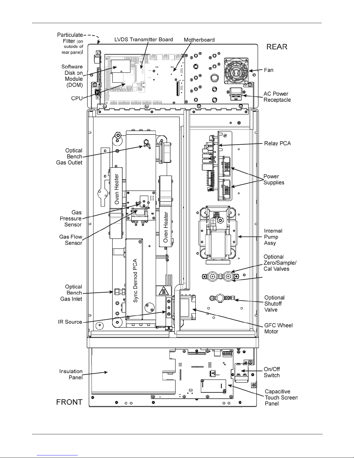
The internal layout of t he T300U (Figure 3-1) differs from the T300/T300M due to the
need to create a thermally insulated, convection-heated oven in which the optical bench
temperature is raised and maintained at a high and very stable temperature. Additionally,
there is a multi-tube, high flow Nafion
dryer t hat removes moisture from the sample
gas.
Page 16
Getting Started Teledyne API - T300U Addendum to T300/T300M Manual
14 06867D DCN7970
Figure 3-1: T300U Internal Layout
Page 17

Teledyne API - T300U Addendum to T300/T300M Manual Getting Started
06867D DCN7970 15
3.3. CONNECTIONS AND SETUP
The information found in Section 3.3 of the T300/T300M Operators Manual (P/N
06864) is applicable to the T300U with the exceptions of the Analog and Status Output
connections, as described here.
Note
To maintain compliance with EMC standards, it is required that the cable
length be no greater than 3 meters for all I/O connections, which include
Analog In, Analog Out, Status Out, Control In, Ethernet/LAN, USB, RS-232,
and RS-485.
3.3.1. ELECTRICAL CONNECTIONS
The electrical connection instructions in the T300/T300M Operators Manual apply
except as differentiated herein.
3.3.1.1. Connecting Analog Outputs
The analog outputs for the T300U are different from those of the T300/T300M. Unlike
the T300/T300M which can include options for measuring both O
2
and CO, the T300U
is a single gas analyzer (CO) and therefore does not require the fully configurable
version of the analog outputs. The following information replaces the Analog Outputs
Section of the T300/T300M Operators Manual.
The T300U is equipped with several analog output channels accessible through a
connector on the rear panel of the instrument:
• Channels A1 and A2 output a signal that is proportional to the CO concentration of
the sample gas.
• The default analog output voltage setting of these channels is 0 to 5 VDC with
a reporting range of 0 to 500 ppb.
• An optional Current Loop output is available for each.
• The output labeled A4 is special. It can be set by the user to output any one a
variety of diagnostic test functions.
• The default analog output voltage setting of these channels is also 0 to 5 VDC.
• See Section 4.2.2 for a list of available functions.
• There is NO optional Current Loop output is available for Channel A4.
Table 3-1 lists the default settings for each of these channels.
Page 18
Getting Started Teledyne API - T300U Addendum to T300/T300M Manual
16 06867D DCN7970
Table 3-1: Analog Output Data Type Default Settings
PARAMETER CHANNEL DEFAULT SETTING
A1
A2
A3
A4
1
DATA TY PE
1
CONC1 CONC2
Not
Available
TEST
CHANNEL
RANGE
0 – 5 VDC2
OVERRANGE
ON
REC OFS
0 mVDC
AUTO CAL.
ON
CALIBRATED
NO
OUTPUT
ON
1
See Table A-6 of T300/T300M Appendix A for definitions of these DAS data types
2
Optional current loop outputs are available for analog output channels A1& A2.
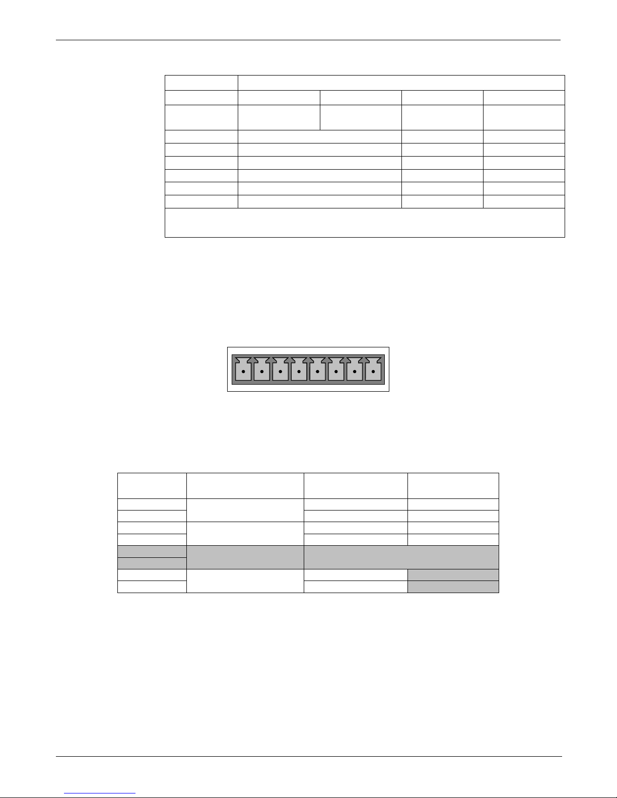
To access these signals attach a strip chart recorder and/or data-logger to the appropriate
analog output connections on the rear panel of the analyzer. Pin-outs for the analog
output connector are:
ANALOG OUT
A1 A2 A3 A4
+ - + - + - + -
Figure 3-2: T300U Analog Output Connector
Table 3-2: Analog Output Pin Outs
Pin Analog Output
Standard Voltage
Output
Current
Loop Option
1
A1
V Out
I Out +
2
Ground
I Out -
3
A2
V Out
I Out +
4
Ground
I Out -
5
A3
NOT USED
6
7
A4
V Out
Not Available
8
Ground
Not Available
Page 19

Teledyne API - T300U Addendum to T300/T300M Manual Getting Started
06867D DCN7970 17
3.3.2. CONNECTING STATUS OUTPUTS
The information found in Section 3.3.1.5. of the T300/T300M Operators Manual is
correct with the following exception:
Table 3-3: Status Output Pin Assignments
Output #
Status
Definition
Condition
1 SYSTEM OK On if no faults are present.
2
CONC VALID
On if CO concentration measurement is valid.
If the CO concentration measurement is invalid, this bit is OFF.
3 HIGH RANGE
On if unit is in high range of
DUAL
or
AUTO
Range Modes.
4 ZERO CAL On whenever the instruments ZERO point is being calibrated.
5 SPAN CAL On whenever the instruments SPAN point is being calibrated.
6 DIAG MODE On whenever the instrument is in DIAGNOSTIC mode.
7
A-REF On whenever the instrument in is A-REF mode.
8 SPARE
D
EMITTER BUSS The emitters of the transistors on pins 1-8 are bussed together.
+
DC POWER + 5 VDC
Digital Ground The ground level from the analyzer’s internal DC Power Supplies.
Page 20
Getting Started Teledyne API - T300U Addendum to T300/T300M Manual
18 06867D DCN7970
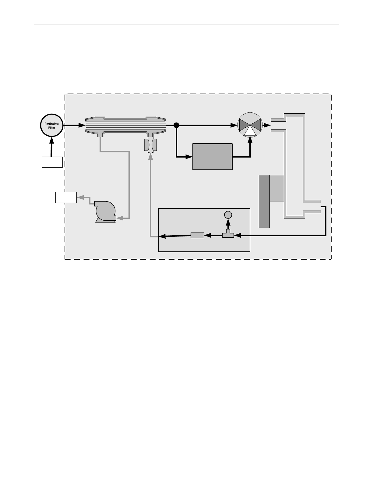
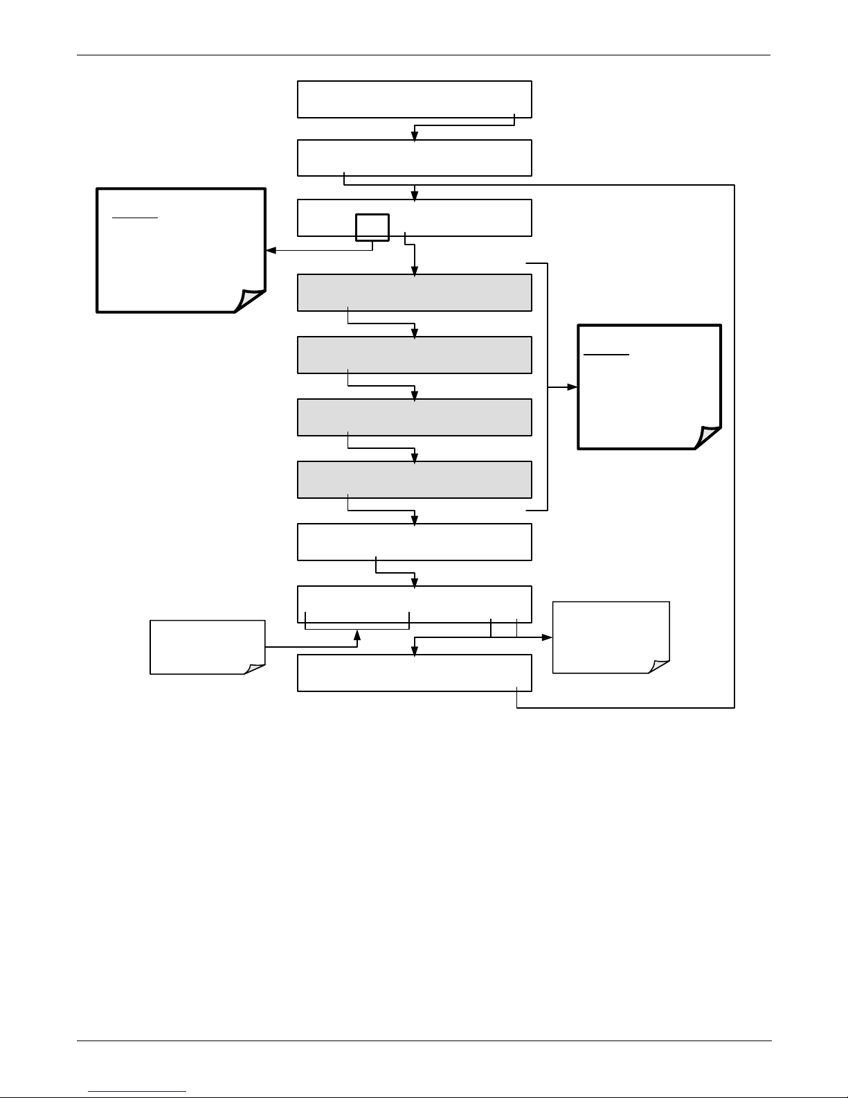
3.3.3. PNEUMATICS
The pneumatic flow of the T300U is different from the T300/T300M in two ways:
• The addition of a high-flow multi-tube Nafion
dryer.
• An additional gas path that passes the sample gas though a CO
scrubber used
during the auto-reference cycle.
INST RUM ENT CHASSIS
CO
Scrubber
Flow / Pressure
Sensor PCA
SAMPLE
PRESSURE
SENSOR
FLO W
SENSOR
Samp l e Gas
Flow Control
SAMPLE GAS
INLET
EXHAUST
GAS OUT LET
/
PUMP
GFC Wheel
Housing
GF C Motor Heat Sync
SAMPLE CH AMBER
Auto-
Reference
Valve
Multi-Tube Nafion
Dryer
3 2
1
NO COM
NC
Figure 3-3: T300U Internal Pneumatic Flow – Basic Configuration
Page 21
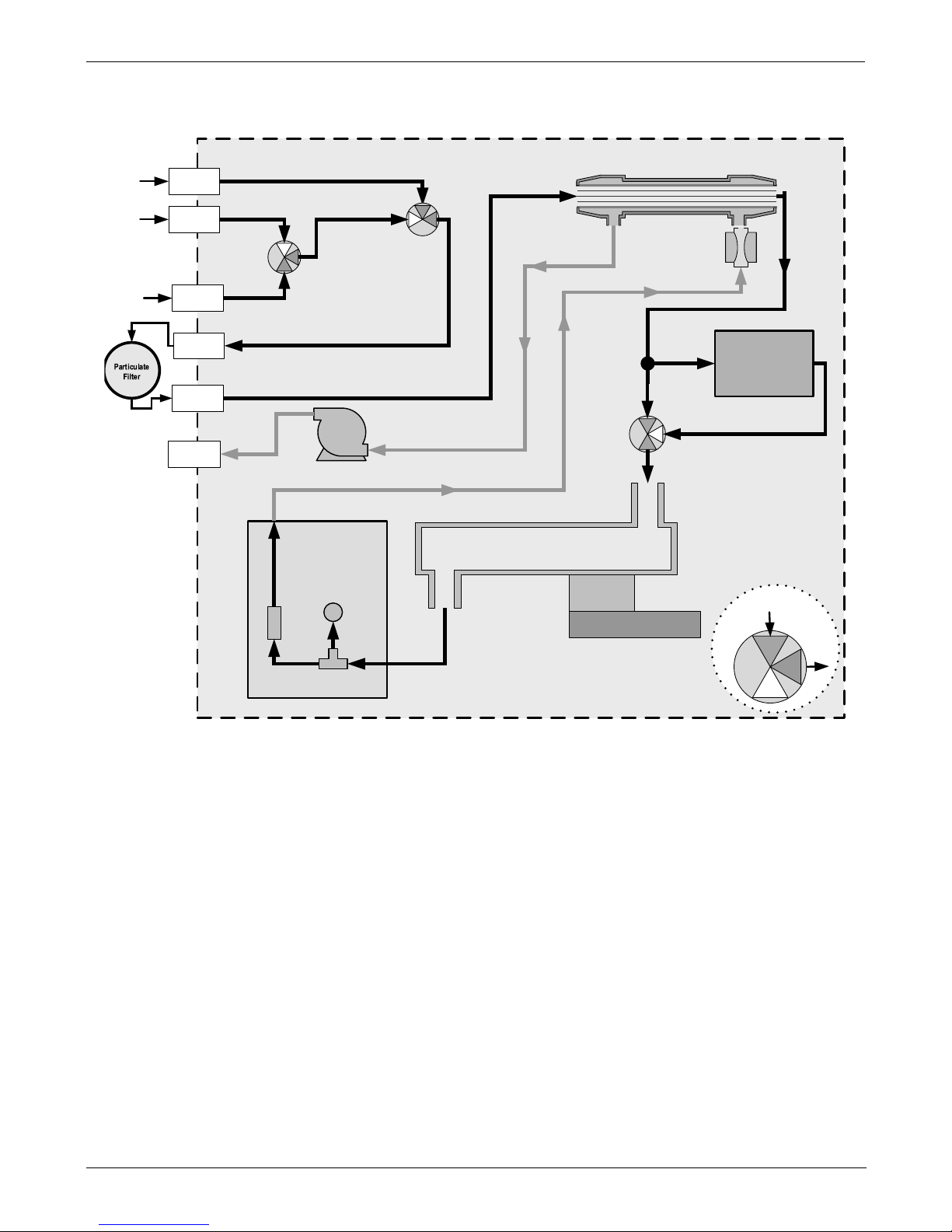
Teledyne API - T300U Addendum to T300/T300M Manual Getting Started
06867D DCN7970 19
INSTRUMENT CH ASSIS
SAMPLE
PRESSURE
SENSOR
FLO W
SENSOR
Samp l e Gas
Flow Control
Flow / Pressure
Sensor PCA
EXHAUST
GAS OUTLET
PUMP
SAMPLE
GAS I N L ET
ZERO INLET
SPA N
INLET
Sample / Cal
Valve
Zero / Span
Valve
Zero
Gas
In
Sam ple
Gas
In
Span
Gas
In
CO
Scrubber
Auto-
Reference
Valve
Multi-Tube Nafion
Dryer
SAMPLE CHAMBER
GFC Wheel
Housing
GF C Motor Heat Sync
SAMPLE
FILTE R OUT
SAMPLE
FILTER IN
VALVE KEY:
NO
COM
NC
Figure 3-4: T300U Internal Pneumatic Flow – Ambient Zero/Span Valves (OPT 50A)
Page 22

Getting Started Teledyne API - T300U Addendum to T300/T300M Manual
20 06867D DCN7970
3.4. STARTUP, FUNCTIONAL CHECKS, AND INITIAL
CALIBRATION
IMPORTANT IMPACT ON READINGS OR DATA
The analyzer’s cover must be installed and securely fastened to ensure that the
convection oven portion of the internal layout is capable of properly creating
and controlling temperatures of the analyzer’s optical bench.
3.4.1. STARTUP
The process for starting and warming up the T300U is identical to that described in
Section 3.4.1 of the T300/T300M Operators Manual (P/N 06864) except:
• It is best to allow the T300U to operate uninterrupted for at least 2 hours to allow the
temperature of all areas of the convection oven area to equalize.
3.4.2. WARNING MESSAGES
The information found in Section 3.4.2 of the T300/T300M Operators Manual (P/N
06864) is applicable to the T300U with the following exceptions (marked by bold print
and heavy outline):
Table 3-4: Possible Warning Messages at Start-Up
MESSAGE MEANING
ANALOG CAL WARNING
The instrument's A/D circuitry or one of its analog outpu ts is not cali brated.
AZERO WARN 1.001
Auto-reference ratio below the specified limits.
BENCH TEMP WARNING
Optical bench temperature is outside the specified limits.
BOX TEMP2 WARNING
The temperature inside the T300U chassis is outside the specified limits
(Replaces BOX TEMP WARNING)
CANNOT DYN SPAN
Remote span calibration failed while the dynamic span feature was set to turned on
CANNOT DYN ZERO
Remote zero calibration failed while the dynamic zero feature was set to turned on
CONFIG INITIALIZED
Configuration was reset to factory defaults or was erased.
DATA INITIALIZED
DAS data storage was erased.
OVEN TEMP WARNING
The temperature of the insulated convection oven area of the analyzer is
outside the specified limits.
PHOTO TEMP WARNING
Photometer temperature outside of warning limits.
REAR BOARD NOT DET
The CPU is unable to communicate with the motherboard.
RELAY BOARD WARN
The firmware is unable to communi cat e w ith the relay boar d.
SAMPLE FLOW WARN
The flow rate of the sample gas is outside the specified limits.
SAMPLE PRESS WARN
Sample pressure outside of operational parameters.
SAMPLE TEMP WARN
The temperature of the sample gas is outside the specified limits.
SOURCE WARNING
The IR source may be faulty.
SYSTEM RESET
The computer was rebooted.
WHEEL TEMP WARNING
The Gas Filter Correlation wheel temperature is outside the specified limits.
Page 23

Teledyne API - T300U Addendum to T300/T300M Manual Getting Started
06867D DCN7970 21
3.4.3. FUNCTIONAL CHECKS
The information found in Section 3.4.3 of the T300/T300M Operators Manual (P/N
06864) regarding performing an initial functional check of the analyzer is applicable to
the T300U with the following exception(s).
The Test functions available from the front panel of the T300U are:
1
These range displays appear if the
instrument’s reporting ranges are set for either
the DUAL or AUTO modes
.
2
Only appears if analog output A4 is actively
reporting a TEST FUNCTION
SAMPLE RANGE=50.000 PPM CO= XXXX
<TST TST> CAL SETUP
Toggle <TST TST> buttons
to scroll through list of
functions
•
RANGE=[Value] PPB
•
RANGE1=[Value] PPB
1
•
RANGE2=[Value] PPB
1
•
STABIL=[Value] PPB
1
•
CO MEAS=[Value] MV
•
CO REF=[Value] MV
•
MR RATIO=[Value]
•
AZERO RATIO=[Value]
•
PRES=[Value] IN-HG-A
•
SAMP FL=[Value] CC/M
•
BENCH TEMP=[Value]ºC
•
WHEEL TEMP=[Value]ºC
•
OVEN TEMP=[Value]ºC
•
SAMPLE TEMP=[Value]ºC
•
PHT DRIVE=[Value] MV
•
SLOPE=[Value]
•
OFFSET=[Value] PPB
•
TEST=[Value] MV
2
•
TIME=[HH:MM:SS]
Page 24

Getting Started Teledyne API - T300U Addendum to T300/T300M Manual
22 06867D DCN7970
3.5. INITIAL CALIBRATION
3.5.1. PRE-CALIBRATION STABILIZ ATION
Before initially calibrating the T300U it must be allowed to operate for a minimum of 12
hours.
After this stabilization period is complete and just prior to performing the initial
calibration, manually initiate an auto-reference measurement by following the
instructions in Section 4.4.
3.5.2. BASIC CO CALIBRATION SETUP
Note
The following procedure assumes that the instrument does not have any o f the
available Zero/Span Valve Options installed.
To perform the following calibration you must have sources for zero air and span gas
available for input into the sample port on the back of the analyzer. See Section 3.3.2.1
of the T300/T300M Operators Manual (P/N 06864) for instructions for connecting these
gas sources.
Note
All Gas lines should be PTFE (Teflon), FEP, glass, stainless steel or brass.
3.5.2.1. Calibration Gases
The information found in Section 3.3.2.11 of the T300/T300M Operators Manual (P/N
06864) is applicable to the T300U with the following exception:
ZER O AI R
Zero air is a gas that is similar in chemical composition to the earth’s atmosphere but
scrubbed of all components that might affect the analyzer’s readings, in this case CO
and water vapor.
For the T300U this gas MUST include at least 5% O
2
(required for the proper operation
of the analyzer’s CO scrubber).
For analyzers without an IZS or external zero air scrubber option, a zero air generator
such as the Teledyne Instruments Model 701 can be used.
Note
The zero air generator MUST be equipped with a hydrocarbon (HC) & CO
scrubber option. For the Teledyne Instruments M701, this is Option 2B.
Page 25

Teledyne API - T300U Addendum to T300/T300M Manual Getting Started
06867D DCN7970 23
3.5.3. BASIC CO CALIBRATION PROCEDURE
The initial calibration should be carried out using the same reporting range set up as
used during the analyzer’s factory calibration. This will allow you to compare your
calibration results to the factory calibration as listed on the Final Test and Validation
Data Sheet.
Because the T300U’s analog output setup differs from that of the T300/T300M and
because the T300U could not be modified to include the optional CO
2
or O2 sensor
packages, there are some minor differences in the initial Calibration procedure as
described in Section 3.4 of the T300/T300M Operators Manual (P/N 06864).
These differences are:
• STEP 1 - Set Lim it s :
• Reporting Range Limit should be set to 50.000 ppm .
• STEP 2 – Dilution Ratio:
• Ignore this step
• STEP 3 – Set CO Span Gas Concentration
• The CO span gas concentration should be 40.000 ppm
• STEP 4 – Zero/Span CalibratiOn
• Set the display to show the STABILITY test function.
• There is no GAS TO CAL step because there are no gas options to choose in
the T300U.
Ignore Sections 3.4.4.3 and 3.4.4.4 of the T300/T300M Operators Manual (P/N 06864)
since they relate to sensor options not available on the T300U.
Page 26

Getting Started Teledyne API - T300U Addendum to T300/T300M Manual
24 06867D DCN7970
This page intentionally left blank.
Page 27

06867D DCN7970 25
4. T300U OPERATING INSTRUCTIONS
4.1. SUMMARY OF SETUP AND OPERATION DIFFERENCES
BETWEEN T300U AND T300/T300M ANALYZERS.
For the most part the setup and operation instruction for the T300U are the same as those
described in Sections 4, 5, and 6 of the T300/T300M manual (P/N 06864) with the
following exceptions:
• There are several additional Test functions related to the optical bench’s convection
oven and the A-REF cycle (see Section 4.2.2).
• There is and additional warning message related to the optical bench’s convection
oven (see Section 3.4.2)
• There is an additional operating mode, AREF, which can be used to force the
instrument to make an auto-reference measurement and calculation.
• There are several additional DAS trigger events and parameters (see Appendix A of
this addendum).
• The reporting range setup and configuration of the A1 and A2 analog outputs is
different (see Section 4.3).
• The optional O
2
and CO2 sensor packages available for the T300/T300M are not
available on the T300U. Ignore all references to these in the T300/T300M
Operators Manual (P/N 06864) when operating the T300U.
• The set of available VARS is different (see Section 4.5).
• The set of submenus available under the DIAG menu is slightly different (see
Section 4.6).
• The set of signals available under the DIAG SIGNAL I/O submenu is different
(see Appendix A of this addendum).
• Because of the difference in how the analog output ranges are implemented
between the T300/T300M and the T300U, there are some differences in DIAG
ANALOG I/O CONFIGURATION submenu (see Section
4.7.1).
• There are no alarm outputs available of the T300U. Ignore Sec ti on 5.10 of the
T300/T300M Operators Manual (P/N 06864).
• There is an additional STATUS OUTPUT related to the A-REF cycle (see Section
3.3.2).
• The default Hessen protocol gas ID and status flag list is different from that of the
T300/T300M (see Secti on 4.7.4).
Page 28

T300U Operating Instructions Teledyne API - T300U Addendum to T300/T300M Manual
26 06867D DCN7970
4.2. OPERATING MODES
The information found in Section 4 of the T300/T300M Operators Manual (P/N 06864)
is applicable to the T300U with the following exception(s).
The following table supersedes Table 4-1 of the T300/T300M Operators Manual (P/N
06864).
Table 4-1: T300U Operating Modes
MODE
MEANING
A-REF
The analyzer is currently recording values for CO MEAS and CO ref, while the
sample gas stream is being routed through the CO scrubber of the autoreference gas path.
DIAG
One of the analyzer’s diagnostic modes is being utilized.
M-P CAL
This is the basic, multi-point calibration mode of the instrument and is activated by pressing the
CAL key.
SAMPLE
Sampling normally, flashing indicates adaptive filter is on.
SAMPLE A
Indicates that unit is in
SAMPLE
Mode and
AUTOCAL
feature is activated.
SETUP
SETUP mode is being used to configure the analyzer (CO sampling will continue during this
process as well as data collection and output).
SPAN CAL A
1
Unit is performing span cal procedure initiated automatically by the analyzer’s AUTOCAL
feature.
SPAN CAL M1
Unit is performing span cal procedure initiated manually by the user.
SPAN CAL R1
Unit is performing span cal procedure initiated remotely via the RS-232, RS-4485 or digital i/o
control inputs.
ZERO CAL A1
Unit is performing zero cal procedure initiated automatically by the analyzer’s AUTOCAL
feature.
ZERO CAL M1
Unit is performing zero cal procedure initiated manually by the user.
ZERO CAL R1
Unit is performing zero cal procedure initiated remotely via the RS-232, RS-4485 or digital I/O
control inputs.
1
The various CAL modes allow calibration of the analyzer. Because of their importance, these modes are described
separately in Section 9 of the T300/T300M Operators Manual (P/N 06864).
Page 29

Teledyne API - T300U Addendum to T300/T300M Manual T300U Operating Instructions
06867D DCN7970 27
4.2.1. AUTO-REFERENCE MODE (A-REF)
One of the most significant differences between the T300/T300M and the T300U
analyzers is the auto-reference measurement feature. In this mode, the analyzer makes
special measurements and calculations that are applied to the CO concentration
calculation to dramatically improve interferent rejection as well as compensate for
changes in ambient temperature of the sample gas and age related drift of the optical
bench components (see Section 8.1.1 for detailed information about how and when this
A-REF feature occurs).
When in A-REF mode, the analyzer:
• Freezes the CO concentration reading displayed on the front panel and output via
the analog outputs or COM Ports.
• Displays AUTO-REF in the Mode field of the analyzer’s front panel (see menu chart,
Figure 4-1).
• Sets the A-REF status output (pin-7 on the status output connector) to high.
Figure 4-1: Display during A-REF Mode
Note
Initiating a calibration through either the front panel touchscreen, the COM
ports or digital control inputs terminates the A-REF mode.
Also, when the instrument is in Calibration Mode, the A-REF mode is
suppressed until the instrument exits Calibration Mode.
See Section 4.4 for information about changing the A-REF cycle time or manually
initiating an auto-reference measurement.
Page 30

T300U Operating Instructions Teledyne API - T300U Addendum to T300/T300M Manual
28 06867D DCN7970
4.2.2. TEST FUNCTIONS
The information found in Section 4.1.1 of the T300/T300M Operators Manual (P/N
06864) is applicable to the T300U with the exception that the following table supersedes
Table 4-2 of the T300/T300M Operato rs Manu al (P/N 06864).
Table 4-2: Test Functions Defined
Parameter Display Title
Units
Meaning
RANGE
- RANGE1
RANGE2
RANGE
PPB, PPM
UGM, MGM
The full-scale limit at which the output range of the analyzer’s Analog
Outputs is currently set.
• THIS IS NO T t he Physic al Range of the instrument. See Section 4.3.2
for more information.
If DUAL or AUTO Range modes have been selected, two RANGE functions
will appear, one for each range.
Stability
STABIL
PPB, PPM
UGM, MGM
Standard deviation of CO concentration readings. Data points are recorded
every ten seconds using the last 25 data points. This function can be reset
to show O
2
or CO2 stability in instruments with those sensor options
installed.
CO Measure
MEAS
MV
The demodulated, peak IR detector output during the measure portion of the
GFC Wheel cycle.
CO Reference
REF
MV
The demodulated, peak IR detector output during the reference portion of
the GFC wheel cycle.
Measurement /
Reference Ratio
MR Rat io
-
The result of CO MEAS divided by CO REF based on readings taken during
the normal sample measurement portion of the A-REF cycle.
This ratio is the primary value used to compute CO concentration. The
value displayed is not linearized.
Auto-Reference
Ratio
AZERO RATIO -
The result of CO MEAS divided by CO REF based on readings
taken during the zero-reference portion of the A-REF cycle.
This ratio is the used to compute a reference correction factor
for computing the CO concentration. The value displayed is
not linearized.
Sample Pressure
PRES
In-Hg-A
The absolute pressure of the Sample gas as measured by a pressure
sensor.
Sample Flow
SAMPLE FL
cm3/min
Sample mass flow rate as measured by the flow rate sensor in the sample
gas stream,
Sample
Temperature
SAM P TEMP
°C
The temperature of the gas inside the sample chamber.
Bench
Temperature
BENCH TEMP
°C
Optical bench temperature.
Wheel
Temperature
WHEEL TEMP
°C
GFC wheel temperature.
Box Temperature
BOX TEMP
°C
The temperature inside the analyzer chassis.
Oven
Temperature
OVEN TEMP
2
°
C
The current temperature of the circulating air inside the T300U’s
convection oven area.
Photo-detector
Temp. Control
Voltage
PHT DRIVE
mV
The drive voltage being supplied to the thermoelectric coolers of the IR
photo-detector by the sync/demod Board.
Slope
SLOPE
-
The sensitivity of the instrument as calculated during the last calibration
activity. The SLOPE parameter is used to set the span calibration point of
the analyzer.
Offset
OFFSET
-
The overall offset of the instrument as calculated during the last calibration
activity. The OFFSET parameter is used to set the zero point of the
analyzer response.
Test Channel
Output
TEST
mV
The raw voltage being output on the analyzer’s A4 analog output. Only
appears when the test channel is assigned a function.
Current Time
TIME
-
The current time. This is used to create a time stamp on DAS readings, and
by the AUTOCAL feature to trigger calibration event s.
Page 31

Teledyne API - T300U Addendum to T300/T300M Manual T300U Operating Instructions
06867D DCN7970 29
4.3. SETUP RNGE: ANALO G OU TP UT REPORTING RANGE
CONFIGURATION
4.3.1. PHYSICAL R ANGE VERSU S ANALOG OUTPUT REPORTING
RANGES
Functionally, the T300U analyzer has one hardware “physical range” that is capable of
determining CO concentrations between 0 ppb and 100,000 ppb. This architecture
improves reliability and accuracy by avoiding the need for extra, switchable, gainamplification circuitry. Once properly calibrated, the analyzer’s front panel will
accurately report concentrations along the entire span of its physical range. T300U
analyzer’s physical range can create data resolution problems for most analog recording
devices. For example, in an application where the expected concentration of CO is
typically less than 1000 ppb, the full scale of expected values is only 1% of the
instrument’s 100,000 ppb physical range. Unmodified, the corresponding output signal
would also be recorded across only 1% of the range of the recording device.
The T300U solves this problem by allowing the user to select a scaled reporting range
for the analog outputs that only includes that portion of the physical range relevant to the
specific application.
Note
Only the reporting range of the analog outputs is scaled.
Both the DAS values stored in the CPU’s memory and the concentration
values reported on the front panel are unaffected by the settings chosen for the
reporting range(s) of the instrument.
4.3.2. ANALOG OUTPUT RANGES FOR CO CONCENTRATION
The analyzer has two active analog output signals related to CO concentration that are
accessible through a connector on the rear panel.
Not Used
ANALOG OUT
A1 A2 A3 A4
+
- + - + - + -
CO concentration
outputs
HIGH range when DUAL
mode is selected
Test Channel
Output
LOW range when DUAL
mode is selected
Figure 4-2: Analog Output Connector Pin Out
Page 32

T300U Operating Instructions Teledyne API - T300U Addendum to T300/T300M Manual
30 06867D DCN7970
The A1 and A2 channels output a signal that is proportional to the CO c oncent ratio n of
the sample gas. They can be configured:
• With independent reporting ranges reporting a “single” output signal (SNGL Mode,
see Section 4.3.3).
• Be to operate completely independently (DUAL mode, see Section 4.3.4). In this
mode the user can set the measure span and signal scale of each output in a
variety of combinations (but not the units of measure).
EXAMPLE:
A1 OUTPUT: Output Signal = 0-5 VDC representing 0-1000 ppb concentration
values
A2 OUTPUT: Output Signal = 0-10 VDC representing 0-500 ppb concentration
values.
• Or to automatically switch between the two ranges dynamically as the concentration
value fluctuates (AUTO modes, see Section 4.3.5).
Both the A1 and A2 outputs can be:
• Configured full scale outputs of: 0 - 0.1 VDC; 0 - 1VDC; 0 - 5VDC or; 0 - 10VDC.
• Equipped with optional 0-20 mADC current loop drivers and configured for any
current output within that range (e.g. 0-20, 2-20, 4-20, etc.).
The user may also add a signal offset independently to each output (see Section 4.7.1) to
match the electronic input requirements of the recorder or data logger to which the
output is connected.
DEFAULT SETTINGS
The default setting for these the reporting ranges of the analog output channels A1 and
A2 are:
• SNGL mode
• 0 to 500.0 ppb
• 0 to 5 VDC
Reporting range span may be viewed via the front panel by viewing the RANGE test
function. If the DUAL or AUTO modes are selected, the RANGE test function d will
be replaced by two separate functions, RANGE1 & RANGE2. Reporting range status
is also available as output via the external digital I/O status bits.
Note
Upper span limit setting for the individual range modes are shared. Resetting
the span limit in one mode also resets the span limit for the corresponding
range in the other modes as follows:
SNGL DUAL AUTO
Range
Range1 (Low)
Low Range
Range2 (Hi)
High Range
Page 33
Teledyne API - T300U Addendum to T300/T300M Manual T300U Operating Instructions
06867D DCN7970 31
4.3.3. RNGE MODE SNGL: CONFIGURING THE T300U ANALYZER
FOR SINGLE RANGE MODE
The single range mode sets a single maximum range for the both the A1 and A2 analog
outputs. If the single range is selected both outputs are slaved together and will
represent the same reporting range span (e.g. 0-50 ppm), however, their electronic signal
levels may be configured for different ranges (e.g. 0-10 VDC vs. 0-0.1 VDC.
This Reporting range can be set to any value between 0.1 ppb and 10,000 ppb. To select
SINGLE range mode and set the upper limit of the reporting range, press:
SETUP PRIMARY SETUP MENU
CFG
DAS
RNGE PASS CLK
MORE
EXIT
SAMPLE
RANGE
=50.000 PPM CO= XXXX
<TST TST> CAL SETUP
SETUP
RANGE MODE MENU
MODE SET UNIT EXIT
SETUP
RANGE MODE
:SNGL
SNGL DUAL AUTO ENTR EXIT
SETUP RANGE MODE
:SNGL
SNGL DUAL AUTO ENTR EXIT
SETUP RANGE MODE MENU
MODE SET UNIT EXIT
SETUP RANGE
:500.0 Conc
0 0 5 0 0 .0 ENTR EXIT
Toggled these buttons
to select the upper
SPAN limit for the
reporting range
EXIT
discards the new
setting
ENTR accepts the
new setting
Note
This is the default reporting range mode for the analyzer.
Page 34
T300U Operating Instructions Teledyne API - T300U Addendum to T300/T300M Manual
32 06867D DCN7970
4.3.4. RNGE MODE DUAL: CONFIGURING THE T300U ANALYZER
FOR DUAL RANGE MODE
DUAL range mode allows the A1 and A2 outputs to be configured with separate
reporting range spans as well as separate electronic signal levels. The analyzer software
calls these two ranges LOW and HI.
• The LOW range setting corresponds with the analog output labeled A1 on the rear
panel of the instrument and is viewable via the test function RANGE 1.
• The HIGH range setting corresponds with the A2 output and is viewable via the test
function R ANGE 2.
• While the software labels these two ranges as LOW and HI, when in DUAL mode
their upper limits need not conform to that convention. The upper span limit of the
LOW/RANGE1 can be a higher number than
that of HI/RANGE 2
To set the ranges press:
.
SETUP PRIMARY SETUP MENU
CFG DAS RNGE PASS CLK MORE EXIT
SAMPLE RANGE=50.000 PPM CO= XXXX
<TST TST> CAL SETUP
SETUP RANGE MODE MENU
MODE SET UNIT EXIT
SETUP RANGE MODE:SNGL
SNGL DUAL AUTO ENTR EXIT
SETUP RANGE MODE:SNGL
SNGL DUAL AUTO ENTR EXIT
SETUP RANGE MODE MENU
MODE SET UNIT EXIT
SETUP HIGH RANGE:500.0 Conc
0 0 5 0 0 .0 ENTR EXIT
Toggle these buttons
to select the upper
SPAN limit for the
reporting range
EXIT discards the new
setting
ENTR accepts the
new setting
SETUP LOW RANGE:100.0 Conc
0 0 1 0 0 .0 ENTR EXIT
The LOW and HIGH
ranges have separate
slopes and offsets for
computing the CO
concentration.
The two ranges must
be independently
calibrated
.
EXIT discards the
new setting
ENTR accepts the
new setting
Page 35

Teledyne API - T300U Addendum to T300/T300M Manual T300U Operating Instructions
06867D DCN7970 33
4.3.5. RNGE MODE AUTO: CONFIGURING THE T300U ANALYZER
FOR AUTO RANGE MODE
AUTO range mode gives the analyzer to ability to output data via a LOW range
(displayed on the front panel as RANGE1) and HIGH range (displayed on the front
panel as RANGE2) on a single analog output.
When the AUTO range mode is selected, the analyzer automatically switches back and
forth between user-selected LOW & HIGH ranges depending on the level of the CO
concentration.
• The unit will move from LOW range to HIGH range when the CO concentration
exceeds to 98% of the LOW range span limit.
• The unit will return from HIGH range back to LOW range once the CO concentration
falls below 75% of the LOW range span limit.
Page 36

T300U Operating Instructions Teledyne API - T300U Addendum to T300/T300M Manual
34 06867D DCN7970
To set the ranges press:
SETUP PRIMARY SETUP MENU
CFG DAS
RNGE PASS CLK MORE EXIT
SAMPLE RANGE=50.000 PPM CO= XXXX
<TST TST> CAL SETUP
SETUP RANGE MODE MENU
MODE SET UNIT EXIT
SETUP RANGE MODE:SNGL
SNGL DUAL AUTO ENTR EXIT
SETUP RANGE MODE:SNGL
SNGL DUAL AUTO ENTR EXIT
SETUP RANGE MODE MENU
MODE SET UNIT EXIT
SETUP HIGH RANGE:200.0 Conc
0 0 2 0 0 .0 ENTR EXIT
Toggled these buttons
to select the upper
SPAN limit for the
reporting range
EXIT discards the new
setting
ENTR accepts the
new setting
SETUP LOW RANGE:50.0 Conc
0 0 0 5 0 .0 ENTR EXIT
The LOW and HIGH
ranges have separate
slopes and offsets for
computing the CO
concentration.
The two ranges must
be independently
calibrated
.
EXIT discards the
new setting
ENTR accepts the
new setting
IMPORTANT IMPACT ON READINGS OR DATA
Avoid accidentally setting the LOW range (RANGE 1) of the instrument with a
higher span limit than the HIGH range (RANGE 2). This will cause the unit to
stay in the low reporting range perpetually and defeat the function of the AUTO
range mode.
Page 37

Teledyne API - T300U Addendum to T300/T300M Manual T300U Operating Instructions
06867D DCN7970 35
4.3.6. SETUP RNGE UNIT: SETTING THE REPORTING RANGE UNIT
TYPE
The T300U can display concentrations in ppb, ppm, ug/m3, mg/m3 units. Changing units
affects all of the COM port values, and all of the display values for all reporting ranges.
To change the units of measure press:
SETUP CONC UNITS
:PPB
PPB PPM UGM MGM ENTR EXIT
SETUP PRIMARY SETUP MENU
CFG DAS RNGE PASS CLK MORE EXIT
SAMPLE RANGE=50.000 PPM CO= XXXX
<TST TST> CAL SETUP
SETUP RANGE MODE MENU
MODE SET UNIT EXIT
Toggle these buttons
to select the units of
measure for the
reporting ranges
EXIT discards the new
setting
ENTR accepts the
new setting
Note
Concentrations displayed in mg/m3 and ug/m3 use 0C, 760 mmHg for
Standard Temperature and Pressure (STP). Consult your local regulations for
the STP used by your agency.
Note
Once the units of measurement have been changed, the unit MUST be
recalibrated, as the “expected span values” previously in effect will no longer
be valid. Simply entering new expected span values without running the entire
calibration routine is not sufficient.
The following equations give approximate conversions between volume/volume units
and weight/volume units:
CO ppb x 1.25 = CO ug/m
3
CO ppm x 1.25= CO mg/m3
Page 38

T300U Operating Instructions Teledyne API - T300U Addendum to T300/T300M Manual
36 06867D DCN7970
4.4. SETUP MORE AREF: CONFIGURING AND
PERFORMING AUTO-REFERENCE MEASUREMENTS
4.4.1. ADJUSTING THE A-REF MODE CYCLE TIME
The auto-reference measurement feature is initiated by the T300U at regular intervals
(see Section 8.1.1). It is triggered by the timer feature of the analyzers ACAL system,
which uses the instrument’s internal clock.
All T300U analyzers are shipped from the factory the ACAL system enabled (even on
instruments without calibration valve options installed) and the first ACAL sequence
already programmed and activated with the DELTA TIME parameter set for 4 hours
(for a more detailed discussion of the ACAL system see Section 9.4 of the T300/T300M
Operators Manual).
This interval time can be changed to fit the specific application in which the T300U is
being used. To change the A-REF interval, press:
Page 39
Teledyne API - T300U Addendum to T300/T300M Manual T300U Operating Instructions
06867D DCN7970 37
SETUP PRIMARY SETUP MENU
CFG ACAL DAS RNGE PASS CLK MORE EXIT
SAMPLE RANGE=50.000 PPM CO= XXXX
<TST TST> CAL SETUP
SETUP SEQ1) AUTO-REF,0:04:00
PREV NEXT MODE SET EXIT
NOTE
DO NOT
change the MODE.
Changing to mode to anything
other than AUTO-REF will
disable the A-REF feature and
seriously compromise the
accuracy of the T300U’s CO
measurements
SETUP TIMER ENABLE:ON
<SET SET> EDIT EXIT
SETUP STARTING DATE:01=JAN-07
<SET SET> EDIT EXIT
SETUP STARTING TIME:00:00
<SET SET> EDIT EXIT
SETUP DELTA DAYS:0
<SET SET> EDIT EXIT
SETUP DELTA TIME:04:00
<SET SET> EDIT EXIT
SETUP DELTA TIME:04:00
0 4 :0 0 ENTR EXIT
SETUP DELTA TIME:04:00
<SET SET> EDIT EXIT
Toggle these buttons
to change the A-REF
start interval.
EXIT discards the new
setting
ENTR accepts the
new setting
NOTE
DO NOT
change any of the
settings. Altering these
setting may disable the
A-REF feature and
seriously compromise the
accuracy of the T300U’s
CO measurements
Page 40
T300U Operating Instructions Teledyne API - T300U Addendum to T300/T300M Manual
38 06867D DCN7970
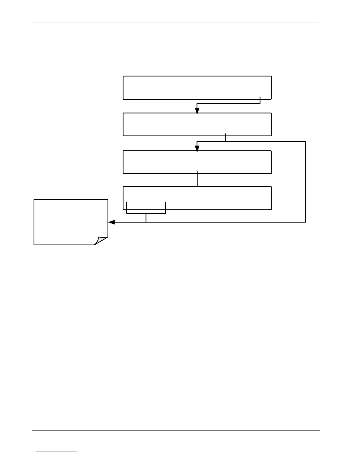
4.4.2. FORCING AN AUTO-REFERENCE MEASUREMENT
Sometimes it is advisable to perform an auto-reference measurement at other times such
as just before calibrating the analyz er.
To manually start an auto-reference measurement cycle, press:
YES initiates an new
A-REF cycle
NO aborts the A-REF
cycle
SETUP PRIMARY SETUP MENU
CFG DAS RNGE PASS CLK MORE EXIT
SAMPLE RANGE=50.000 PPM CO= XXXX
<TST TST> CAL SETUP
SETUP SECONDARY SETUP MENU
COMM VARS DIAG AREF EXIT
SETUP RESET AUTO-REFERENCE?
YES NO
Page 41

Teledyne API - T300U Addendum to T300/T300M Manual T300U Operating Instructions
06867D DCN7970 39
4.5. SETUP MORE VARS: VARIABLES SETUP AND
DEFINITION
The information found in Section 5.8 of the T300/T300M Operators Manual (P/N
06864) is applicable to the T300U with the following exception(s):
• There is no STABIL_GAS variable available under the VARS menu of the T300U.
• The following table supersedes Table 5-3 of the T300/T300M Operators Manual
(P/N 06864).
Table 4-3: T300U VARS Menu
NO. VARIABLE DESCRIPTION
ALLOWED
VALUES
0
DAS_HOLD_OFF
Changes the internal data acquisition system (DAS) hold-off
time, which is the duration when data are not stored in the
DAS because the software considers the data to be
questionable. That is the case during warm-up or just after
the instrument returns from one of its calibration modes to
SAMPLE mode. DAS_HOLD_OFF can be disabled entirely
in each DAS channel.
Can be between 0.5
and 20 minutes
Default=15 min.
1
CONC_PRECISION
Allows the user to set the number of significant digits to the
right of the decimal point display of concentration and
stability values.
AUTO, 1, 2, 3, 4
Default=AUTO
2
DYN_ZERO
Dynamic zero automatically adjusts offset and slope of the
CO response when performing a zero point calibration
during an AutoCal (Section 7).
ON/OFF
3
DYN_SPAN
Dynamic span automatically adjusts slope and slope of the
CO response when performing a zero point calibration
during an AutoCal (Section 7).
Note that the DYN_ZERO and DYN_SPAN features are not
allowed for applications requiring EPA equivalency.
ON/OFF
4
CLOCK_ADJ
Adjusts the speed of the analyzer’s clock. Choose the +
sign if the clock is too slow, choose the - sign if the clock is
too fast.
-60 to +60 s/day
Page 42

T300U Operating Instructions Teledyne API - T300U Addendum to T300/T300M Manual
40 06867D DCN7970
4.6. SETUP MORE DIAG: DIAGNOSTICS FUNCTIONS
The information found in Section 5.9 of the T300/T300M Operators Manual (P/N
06864) is applicable to the T300U with the following exception(s):
• There is no DISPLAY SEQUENCE CONFIGURATION submenu available under
the DIAG menu of the T300U.
• The following table supersedes Table 5-4 of the T300/T300M Operators Manual
(P/N 06864).
Table 4-4: T300U Diagnostic (DIAG) Submenus
DIAGNOSTIC FUNCTION AND MEANING
Front Panel
Mode Indicator
SIGNAL I/O: Allows observation of all digital and analog signals in the
instrument. Allows certain digital signals such as valves and heaters
to be toggled ON and OFF.
DIAG I/O
See
T300/T300M
Manual
ANALOG OUTPUT: When entered, the analyzer performs an analog
output step test. This can be used to calibrate a chart recorder or to
test the analog output accuracy.
DI AG AOU T
See
T300/T300M
Manual
ANALOG I/O CONFIGURATION: This submenu allows the user to
configure the analyzer’s four analog output channels, including
choosing what parameter will be output on each channel. Instructions
that appear here allow adjustment and calibration the voltage signals
associated with each output as well as calibration of the analog to
digital converter circuitry on the motherboard.
DI AG AIO
4.7.1
ELECTRIC TEST: The analyzer is performing an electric test. This test
simulates IR detector signal in a known manner so that the proper
functioning of the sync/demod board can be verified.
DIAG OPTIC
See
T300/T300M
Manual
DAR K CALIBRATION: The analyzer is performing a dark calibration
procedure. This procedure measures and stores the inherent dc
offset of the sync/demod board electronics.
DIAG ELEC
See
T300/T300M
Manual
PRESSURE CALIBRATION: The analyzer records the current output
of the sample gas pressure sensor. This value is used by the CPU to
compensate the CO concentration.
DIAG PCAL
See
T300/T300M
Manual
FLOW CALIBRATION: This function is used to calibrate the gas flow
output signals of sample gas and ozone supply. These settings are
retained when exiting DIAG.
DIAG FCAL
See
T300/T300M
Manual
Page 43

Teledyne API - T300U Addendum to T300/T300M Manual T300U Operating Instructions
06867D DCN7970 41
4.7. ANALOG OUTPUT CONFIGURATION
4.7.1. ANALOG I/O CONFIGURATION
Because the manner in which the analog outputs are implemented differs between the
T300/T300M and the T300U, ther e are significant diff erences in the manner i n which
the ANALOG I/O are manipulated.
This section replaces Section 5.9.3 of the T300/T300M Operators Manual (P/N 06864).
Table 4-5: DIAG - Analog I/O Functions
SUB MENU
FUNCTION
AOUT CALIBRATED
Initiates a calibration of the A1, A2 and A4 analog output channels that determines
the slope and offset inherent in the circuitry of each output. These values are stored
in the and applied to the output signals by the CPU automatically
CONC_OUT_1
1
Sets the basic electronic configuration of the A1 output. There are four options:
• RANGE: Selects the signal type (voltage or current loop) and level of the output
• A1 OFS: Allows them input of a DC offset to let the user manually adjust the
output level
• AUTO CAL: Enables / Disables the AOUT CALIBRATION Feature
• CALIBRATED: Performs the same calibration as AOUT CALIBRATED, but on this
one channel only.
CONC_OUT_2
1
Sets the basic electronic configuration of the A2 output. There are three options:
• RANGE: Selects the signal type (voltage or current loop) and level of the output
• A2 OFS: Allows them input of a DC offset to let the user manually adjust the
output level
• AUTO CAL: Enables / Disables the AOUT CALIBRATION Feature
• CALIBRATED: Performs the same calibration as AOUT CALIBRATED, but on this
one channel only.
TEST OUTPUT
1
Sets the basic electronic configuration of the A4 output. There are three options:
• RANGE: Selects the signal type (voltage or current loop) and level of the output
• A4 OFS: Allows them input of a DC offset to let the user manually adjust the
output level
• AUTO CAL: Enables / Disables the AOUT CALIBRATION Feature
• CALIBRATED: Performs the same calibration as AOUT CALIBRATED, but on this
one channel only.
AIN CALIBRATED
Initiates a calibration of the A-to-D Converter circuit located on the Mother Board.
1
Changes to RANGE or REC_OFS require recalibration of this output.
Page 44

T300U Operating Instructions Teledyne API - T300U Addendum to T300/T300M Manual
42 06867D DCN7970
To configure the analyzer’s three analog outputs, set the electronic signal type of each
channel and calibrate the outputs by:
1. Selecting an output type (voltage or current, if an optional current output driver has
been installed) and the signal level that matches the input requirements of the
recording device attached to the channel.
2. Determining if the over-range feature is needed and turn it on or off accordingly.
3. Considering if a Voltage scale is in use: a bipolar recorder offset may be added to
the signal if required.
4. Choosing a Test Channel parameter to be output on the channel.
5. Calibrating the output channel. This can be done automatically or manually for
each channel.
To access the analog I/O configuration sub menu, press:
Page 45
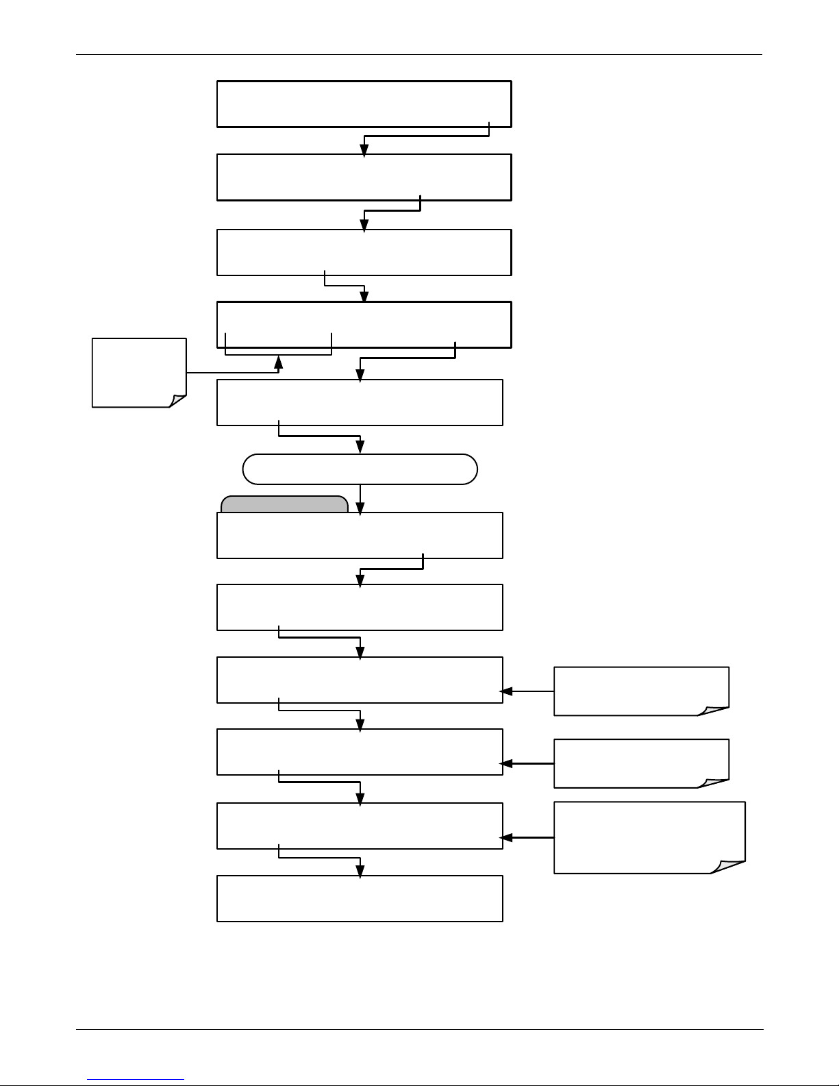
Teledyne API - T300U Addendum to T300/T300M Manual T300U Operating Instructions
06867D DCN7970 43
SETUP PRIMARY SETUP MENU
CFG DAS RNGE PASS CLK MORE EXIT
SAMPLE RANGE=50.000 PPM CO= XXXX
<TST TST> CAL SETUP
SETUP SECONDARY SETUP MENU
COMM VARS DIAG AREF EXIT
SETUP ENTER PASSWORD:818
8 1 8 ENTR EXIT
AIO Configuration Submenu
DIAG SIGNAL I/O
NEXT ENTR EXIT
Continue pressing NEXT until ...
DIAG ANALOG I/O CONFIGURATION
PREV NEXT ENTR EXIT
DIAG AIO A OUTS CALIBRATED: NO
<SET SET> CAL EXIT
DIAG AIO CONC_OUT_1: 5V, OVR, NOCAL
<SET SET> EDIT EXIT
DIAG AIO AIN CALIBRATED: NO
<SET SET> CAL EXIT
DIAG AIO CONC_OUT_2: 5V, OVR, NOCAL
<SET SET> EDIT EXIT
DIAG AIO TEST_OUTPUT: 5V,OVR, NOCAL
<SET SET> EDIT EXIT
Toggle these
buttons to enter
the correct
PASSWORD
Adjusts the signal output
for Analog Output A1
Adjusts the signal output
for Analog Output A2
Selects the parameter top be
output on the TEST channel
and adjusts its signal output
Page 46

T300U Operating Instructions Teledyne API - T300U Addendum to T300/T300M Manual
44 06867D DCN7970
4.7.2. ANALOG OUTPUT CALIBRATION
This section corresponds to Section 5.9.3.2 of t he T300/T300M Operators Man ual (P/N
06864).
ANALOG OUPUT calibration needs to be carried out on first startup of the analyzer
(performed in the factory as part of the configuration process) or whenever re-calibration
is required. The analog outputs can be calibrated automatically, either as a group or
individually, or adjusted manually.
During automatic calibration, the analyzer tells the output circuitry to generate a zero
mV signal and high-scale point signal (usually about 90% of chosen analog signal scale)
then measures actual signal of the output. Any error at zero or high-scale is corrected
with a slope and offset.
In its default state, the analyzer is configured for automatic calibration of all channels,
which is useful for clearing any analog calibration warnings associated with channels
that will not be used or connected to any input or recording device, e.g., datalogger.
However, manual calibration should be used for the 0.1V range or in cases where the
outputs must be closely matched to the characteristics of the recording device. Manual
calibration requires the AUTOCAL feature to be disabled. Automatic group calibration
can be performed via the AOUTS CALIBRATION command, or by the
DIAG>ANALOG I/O CONFIGURATION menu and pressing the CAL button within
each of the output submenus (e.g. CONC_OUT_1, CONC_OUT_2 or
TEST_OUTPUT).
MANUAL CALIBRATION OF ANALOG OUTPUTS CONFIGURED FOR CURRENT LOOP RANGES
The information found in Section 5.9.3.7 of the T300/T300M Operators Manual (P/N
06864) is applicable to the T300U with the following exception:
• The current output option can only be installed on outputs A1 and A2 of the
T300U
Page 47

Teledyne API - T300U Addendum to T300/T300M Manual T300U Operating Instructions
06867D DCN7970 45
4.7.3. SELECTING A TEST CHANNEL FUNCTION FOR OUTP UT A4
This section replaces Section 5.9.8.1 of the T300/T300M Operators Manual (P/N 06864)
The Test Functions available to be reported on analog output A4 are:
Table 4-6: Test Channels Functions Available on the T300U’s Analog Output
TEST CHANNEL DESCRIPTION ZERO FULL SCALE
NONE TEST CHANNEL IS TURNED OFF
CO MEASURE
The raw output of the optical bench’s IR
detector during the measure phase of the m/r
cycle
0 mV 5000 mV*
CO REFERENCE
The raw output of the optical bench’s IR
detector during the reference phase of the
m/r cycle
0 mV 5000 mV*
SAMPLE PRESSURE
The pressure of gas in the optical bench’s
sample chamber
0 "Hg 40 "Hg-In-A
SAMPLE FLOW
The gas flow rate through the optical bench’s
sample chamber
0 cm
3
/min 6000 cm3/min
SAMPLE TEMP
The temperature of gas in the optical bench’s
sample chamber
0 °C 70 °C
BENCH TEMP
The temperature of optical bench’s itself
0 °C 70 °C
WHEEL TEMP
The temperature of GFC wheel
0 °C 70 °C
OVEN TEMP
The temperature of the circulating air inside
the convection oven section of the T300U’s
interior.
0 °C 70 °C
PHT DRIVE
The drive voltage being supplied to the
thermoelectric coolers of the IR photo-detector by
the sync/demod board.
0 mV 5000 mV
TEMP4
SPARE
Once a function is selected, the instrument not only begins to output a signal on the
analog output, but also adds TEST to the list of Test Functions viewable via the Front
Panel Display.
Page 48
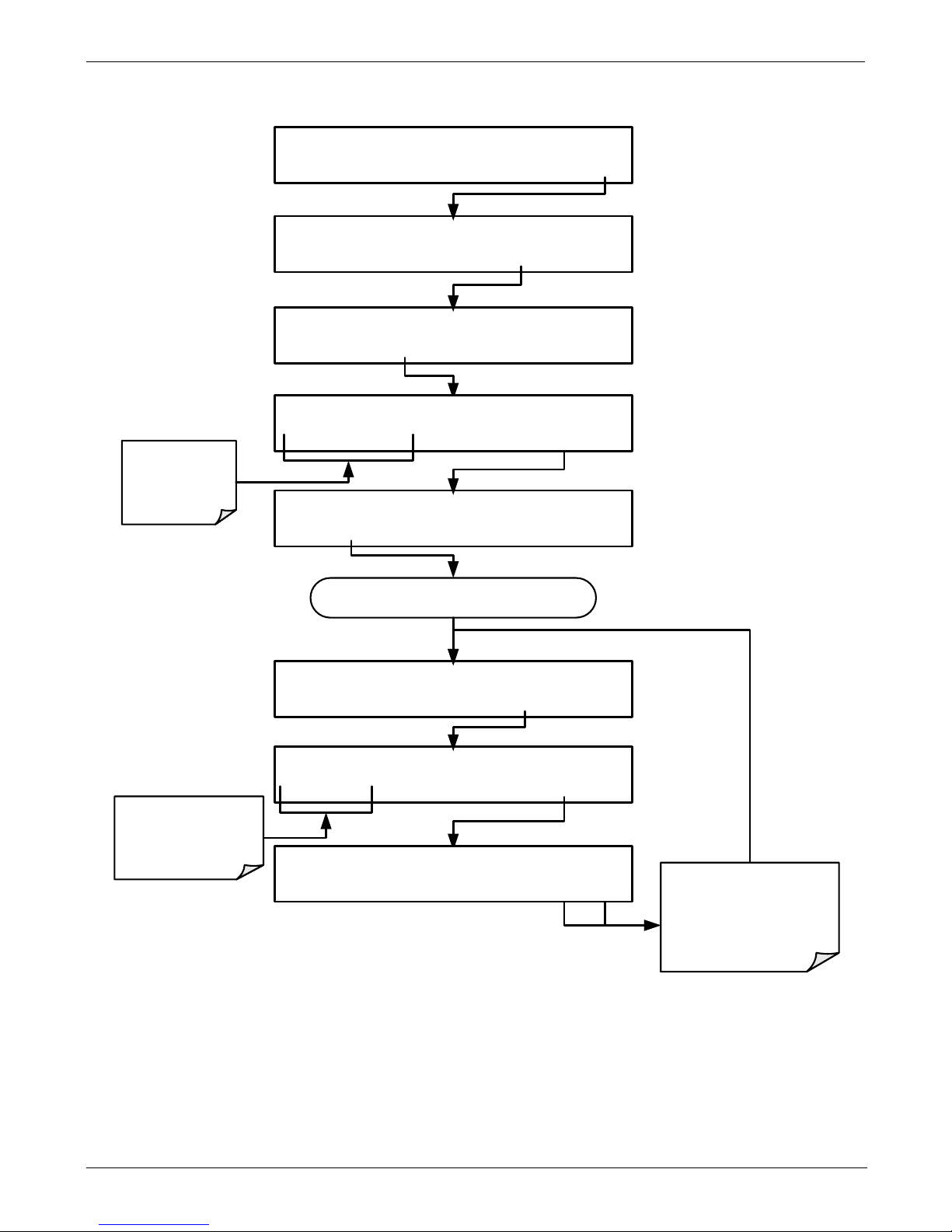
T300U Operating Instructions Teledyne API - T300U Addendum to T300/T300M Manual
46 06867D DCN7970
To activate the TEST Channel and select a function, press:
DIAG TEST CHAN:NONE
PREV
NEXT ENTR EXIT
DIAG SIGNAL I/O
PREV NEXT ENTR EXIT
DIAG TEST CHAN OUTPUT
PREV NEXT ENTR EXIT
Continue pressing NEXT
until ...
Toggle these buttons
to choose a TEST
CHANNEL parameter
DIAG TEST CHANNEL:OVEN TEMP
PREV NEXT ENTR EXIT
EXIT discards the new
setting
ENTR accepts the
new setting
SETUP PRIMARY SETUP MENU
CFG DAS RNGE PASS CLK MORE EXIT
SAMPLE
RANGE=50.000 PPM CO= XXXX
<TST TST> CAL SETUP
SETUP SECONDARY SETUP MENU
COMM VARS
DIAG
AREF EXIT
SETUP
ENTER PASSWORD:818
8 1 8 ENTR EXIT
Toggle these
buttons to enter
the correct
PASSWORD
Page 49

Teledyne API - T300U Addendum to T300/T300M Manual T300U Operating Instructions
06867D DCN7970 47
4.7.4. HESSEN PROTOCOL
The information found in Section 6.7.2 of the T300/T300M Operators Manual (P/N
06864) is applicable to the T300U with the following exception(s):
• There is only one default gas type programmed into the T300U, as follows:
Table 4-7: T300U Hessen GAS ID List
GAS DEFAULT HESSEN GAS ID
CO
310
• The list of Hessen status flags for the T300U is different from that of the
T300/T300M. The following table replaces Table 6-6 of the T300/T300M Operators
Manual (P/N 06864).
Table 4-8: Default Hessen Status Bit Assignmen ts
STATUS FLAG NAME DEFAULT BIT ASSIGNM ENT
WARNING FLAGS
SAMPLE FLOW WARNING 0001
BENCH TEMP WARNING 0002
SOURCE WARNING 0004
BOX TEMP WARNING 0008
WHEEL TEMP WARNING 0010
SAMPLE TEMP WARNING 0020
SAMPLE PRESSURE WARNING 0040
INVALID CONC
(The Instrument’s Front Panel Display Will Show The
Concentration As “XXXX”)
0080
OPERATIONAL FLAGS
In Manual Calibration Mode 0200
In Zero Calibration Mode 0400
In Span Calibration Mode 0800
UNITS OF MEASURE FLAGS
UGM 0000
MGM 2000
PPB 4000
PPM 6000
SPARE/UNUSED BITS
100, 1000, 8000
UNASSIGNED FLAGS (0000)
AZERO WARN RELAY BOARD WARNING
OVEN TEMP WARNING ANALOG CAL WARNING
MP CAL CANNOT DYN ZERO
PHOTO TEMP WARNING CANNOT DYN SPAN
SYSTEM RESET INVALID CONC
REAR BOARD NOT DETECTED
Page 50

T300U Operating Instructions Teledyne API - T300U Addendum to T300/T300M Manual
48 06867D DCN7970
This page intentionally left blank.
Page 51

06867D DCN7970 49
5. CALIBRATION PROCEDURES
Calibration of the T300U should be performed according to the procedures described in
Sections 9 & 10 of the T300/T300M Manual - P/N 06864 with the following notes and
exceptions:
• Delivering span and zero gases for the higher resolution the T300U can be difficult.
Attention must be paid to the quality of the gasses, the level of contaminants in the
gases as well as the history and conditioning of the gas delivery components.
• The analyzer must be continually operating with and adequate flow of sample gas,
for 2 hours prior to performing a calibration (12 hours is recommended for the initial
calibration).
• NOTE: DO NOT calibrate the analyzer if it has been turned off or if no sample gas
has been flowing though it within the last 2 hours.
• After this stabilization period is complete and just prior to performing the initial
calibration, force the instrument to perform an auto-reference measurement by
following the instructions in Secti on 4.4.2 .
5.1. REQUIRED EQUIPMENT, SUPPLIES AND EXPENDABLES
• Gas lines to and from the analyzer should be PTFE or FEP Teflon, glass, stainless
steel or brass only.
• Zero-air source (defined in Section 9.1.1.1 of the T300/T300M Operators Manual).
• Zero air must include at least 5% O
2
(required for the proper operation of the
CO scrubber).
• If a zero air generator such as the Teledyne Instruments M701 is used, it MUST
be equipped with a hydrocarbon (HC) & CO scrubber option. For the Teledyne
Instruments M701, this is Option 2B.
• Span gas source (defined in Section 9.1.1.3 of the T300/T300M Operators Manual).
• A recording device such as a strip-chart recorder and/or data logger (optional).
Data recording device should be capable of bi-polar operation so that negative
readings can be recorded.
• For electronic documentation, the internal data acquisition system can be used.
Note
If any problems occur while performing the following calibration procedures,
refer to Section 11 of this manual for troubleshooting tips
5.2. MANUAL CALIBRATION
The information found in Section 9.2 of the T300/T300M Operators Manual (P/N
06864) is applicable to the T300U with the following exception(s).
• Zero/Span Calibration
• Set the display to show the STABILITY test function (same as the CO STB
function mentioned in the T300/T300M operator’s manual).
• There is no GAS TO CAL step because the T300U cannot be modified to
include the O
2
and CO2 sensor packages.
Page 52

Calibration Procedures Teledyne API - T300U Addendum to T300/T300M Manual
50 06867D DCN7970
5.2.1. MANUAL CALIBRATION CHECKS
The information found in Section 9.2.2 of the T300/T300M Operators Manual (P/N
06864) is applicable to the T300U with the following exception(s).
• Set the display to show the STABILITY test function.
5.2.2. MANUAL CALIBRATION WITH ZERO/ SPAN VALVES
The information found in Section 9.3 of the T300/T300M Operators Manual (P/N
06864) is applicable to the T300U with the following exception(s).
• Set the display to show the STABILITY test function.
• There is no GAS TO CAL step.
5.2.3. MANUAL CALIBRATION CHECKS WITH ZERO/SPAN VALVES
The information found in Section 9.3.2 of the T300/T300M Operators Manual (P/N
06864) is applicable to the T300U with the following exception(s).
• Set the display to show the STABILITY test function.
• There is no GAS TO CAL step.
5.2.4. CALIBRATION WITH REMOTE CONTACT CLOSURES
The information found in Section 9.3.3.3 of the T300/T300M Operators Manual (P/N
06864) is applicable to the T300U with the following exception(s).
Note
It is required that the analyzer be forced to perform an auto-reference
measurement just prior to calibration, however this cannot be forced via the
analyzer’s digital control inputs.
The A-REF measurement can only be initiated using either the instrument’s
front pane interface or via Teledyne Instruments’ APICOM emulator software.
5.2.5. AUTOMATIC ZERO/SPAN CAL/CHECK (AUTOCAL)
The information found in Section 9.4 of the T300/T300M Operators Manual (P/N
06864) is applicable to the T300U with the following exception(s).
• The following table replaces Table 9-2 of the T300/T300M Operators Manual (P/N
06864).
Table 5-1: AUTOCAL Modes
MODE NAME
ACTION
DISABLED
Disables the Sequence
ZERO
Causes the Sequence to perform a zero calibration/check
ZERO-SPAN
Causes the Sequence to perform a zero and span concentration
calibration/check
SPAN
Causes the Sequence to perform a span concentration
calibration/check
AUTO-REF
Causes the analyzer to perform an auto-reference measurement.
Page 53

Teledyne API - T300U Addendum to T300/T300M Manual Calibration Procedures
06867D DCN7970 51
5.2.6. CO CALIBRATION QUALITY
The information found in Section 9.5 of the T300/T300M Operators Manual (P/N
06864) is applicable to the T300U.
5.2.7. CALIBRATION OF OPTIONAL SENSORS
There are no optional sensors in the T300U.
Page 54

Calibration Procedures Teledyne API - T300U Addendum to T300/T300M Manual
52 06867D DCN7970
This page intentionally left blank.
Page 55

06867D DCN7970 53
6. EPA PROTOCOL CAL IBRATION
The information found in Section 10 of the T300/T300M Operators Manual (P/N 06864)
is applicable to the T300U.
Page 56

EPA Protocol Calibration Teledyne API - T300U Addendum to T300/T300M Manual
54 06867D DCN7970
This page intentionally left blank.
Page 57

06867D DCN7970 55
7. INSTRUMENT M AINTENANCE
The information found in Section 11 of the T300/T300M Operators Manual (P/N 06864)
is applicable to the T300U with the following exception(s):
• The oven temperature should be tracked along with the other parameters listed on
Table 11-2 of the T300/T300M Operators Manual (see Table 7-1 below).
7.1. PERFOMING AN AUTO-REFERENCE MEASUREMENT AFTER
MAINTENANCE
It is very important to manually initiate an A-REF measurement whenever any
maintenance is performed on the T300U, particularly if that maintenance is involves:
• Opening the top cover or the front panel while the instrument is making A-REF
measurements.
• Opening the top cover or the front panel at any time when the next ACAL scheduled
A-REF measurement cycle is < 2 hours away.
• Turning off the analyzer at any time when the next ACAL scheduled A-REF
measurement cy cle is < 2 hours away.
This should be done no sooner than 2 hours after the T300U has been operating with the
front panel / top cover properly closed and sealed. One this manual A-REF
measurement is performed; the analyzer will discard any erroneous A-REF ratios that
may have been recorded before the instrument’s oven temperature had a chance to restabilize.
Page 58

Instrument Maintenance Teledyne API - T300U Addendum to T300/T300M Manual
56 06867D DCN7970
This page intentionally left blank.
Page 59

06867D DCN7970 57
Table 7-1: T300U Test Function Record
FUNCTION
OPERATING
MODE*
DATE RECORDED
STABILITY
ZERO CAL
CO MEAS
ZERO CAL
MR RATIO
ZERO CAL
SPAN CAL
PRES
SAMPLE
PHT
DRIVE
SAMPLE
AFTER
WARM-UP
SLOPE
SPAN CAL
OFFSET
ZERO CAL
OVEN
TEMP
SAMPLE
Page 60

Instrument Maintenance TELEDYNE API - T300U ADDENDUM TO T300/T300M MANUAL
58 06867D DCN7970
This page intentionally left blank.
Page 61

06867D DCN7970 59
8. PRINCIPLES OF OPERATION
8.1. MEASUREMENT METHOD
The information found in Section 13.1 of the T300/T300M Operators Manual (P/N
06864) is applicable to the T300U with the following addition. It is recommended that
you read that section before continuing.
8.1.1. AUTO-REFERENCE (A-REF) RATIO
The high er r esol ution of the T300U makes it more susceptible then the T300/T300M to
the effects of a variety of environmental conditions such as:
• Drift related to the age of the optical bench components ( e.g. the IR lamp, the IR
detector, etc.)
• Variations in the temperature of the sample gas (affecting it density).
• Interferents, specifically CO
2
and H2O.
The T300U accounts for these issues by adding an additional component to the CO
concentration calculation call the Auto-reference ratio.
This ratio is arrived at in the same manner as the measure/reference ratio (described in
Section 13.2.1.2 of the T300/T300M Operators Manual) with the difference that that
during the measurements that are to calculate the A-REF ratio, the gas stream is
switched to pass through a scrubber that completely removes all CO from the sample
gas. Therefore the measured difference between CO MEAS and CO R EF represents
the exact state of the sample gas and the optical bench’s sensors without CO present.
INST RUM ENT CHASSIS
CO
Scrubber
Flow / Pressure
Sensor PCA
SAMPLE
PRESSURE
SENSOR
FLO W
SENSOR
Samp l e Gas
Flow Control
EXTERNAL
SAMPLE GAS
INLET
EXHAUST
GAS OUT LET
/
PUMP
GFC Wheel
Housing
GF C Motor Heat Sync
SAMPLE CH AMBE R
Auto-
Reference
Valve
Multi-Tube Nafion
Dryer
Figure 8-1: T300U Gas Flow during Auto-Reference Measurements
Page 62

Principles of Operation Teledyne API - T300U Addendum to T300/T300M Manual
60 06867D DCN7970
The analyzer averages the last five A-REF ratios and multiplies this average by a
constant and the result is included in the final CO calculation as a positive o r negative
offset.
Whenever an A-REF is manually initiated either by using the AREF submenu via the
front panel (see Section 4.4.2) or by a ctivatin g pin-7 of the instrument’s digital control
input connector, all previously stored A-REF ratios are erased and the new ratio
inserted. This allows the user to correct for a bad A-REF reading (e.g. the oven
temperature during the A-REF cycle was too high/low)
The auto-reference measurement takes approximately 15 minutes. To ensure
that the sample chamber of the optical bench is properly purged when switching
between the sample and auto-reference measurements and vice-versa, each autoreference cycle includes a 3 minute dwell period before and after the actual
measurements are made. This cycle is restarted every 4 hours by an ACAL sequence,
programmed at the factory (see Section 4.4).
4 Hours
A-REF DWELL
(3 min)
SAMPLE DWELL
(3 min)
A-REF MEASUREMENT
(≤ 9 min)
≤ 15 min.
Sample Mode
(
Default Condition: Approx
. 3 hrs 45 min
)
Sample Mode
A-REF Valve Switches
Gas Stream to flow
through CO Scrubber
(Initiated by T300U’s ACAL
feature using the internal
clock)
A-REF Valve Switches
Gas Stream away from
CO Scrubber
(Initiated by T300U’s CPU
after sufficient number of
measurements taken to result
in reliable AREF ratio)
Figure 8-2: Auto-Reference Measurement Cycle
8.2. PNEUMATIC OPERATION
With the exceptions to the difference discussed on other portions of this addendum
regarding the A-REF CO scrubber and the Nafion
dryer, the pneumatic operation is the
same as that described in Section 13.3 of the T300/T300M Operators Manual (P/N
06864).
Page 63

Teledyne API - T300U Addendum to T300/T300M Manual Principles of Operation
06867D DCN7970 61
8.2.1. THE A-REF CARBON MONOXIDE SCRUBBER
A special CO scrubber is used to remove all of the CO from the gas stream when the
instrument is performing an auto-reference measurement. The scrubber contains a
substance that catalyses a chemical reaction converting any CO in the gas stream to CO
2
.
Note
To operate properly, the gas flowing though the scrubber must contain at least
5% O2.
This includes calibration gases such as zero air and span gas.
8.2.2. THE A-REF VALVE ASSEMBLY
The aut o-reference valve assembly is located next to the optical bench, at the re ar of t he
analyzer between the Nafion
dryer and the outer wall of the instrument (see Figure
3-1). The following table describes the state of each valve during the analyzer’s various
operational modes (see Figure 8-1).
Table 8-1: Auto-Reference Valve Operating States
Mode Valve State VALVE PORT CONNECTIONS
SAMPLE
(Normal State)
Gas stream from Nafion
Dryer &
SAMPLE inlet
3 2
A-REF DWELL
Gas stream from CO scrubber
1 2
A-REF MEASUREMENT
Gas stream from CO scrubber
1 2
SAMPLE DWELL
Gas stream from Nafion
Dryer &
SAMPLE inlet
3 2
8.2.3. THE NAFION DRYER.
Normal room air contains a certain amount of water vapor. While H2O is a very lowlevel interferent for IR absorption (in the same range as CO) it can cause enough
interference to affect the high-resolution measurements of the T300U.
To account for this the T300U has a special dryer added to the gas stream. The dryer
consists of a bundle of parallel tubes of Nafion
®
, a co-polymer similar to Teflon® that
absorbs water very well but not other chemicals. The multiple tube design of this dryer
creates a large reactive surface without causing a restriction in the higher gas flow rate
required by the T300U that a long single tube style dryer would.
Page 64
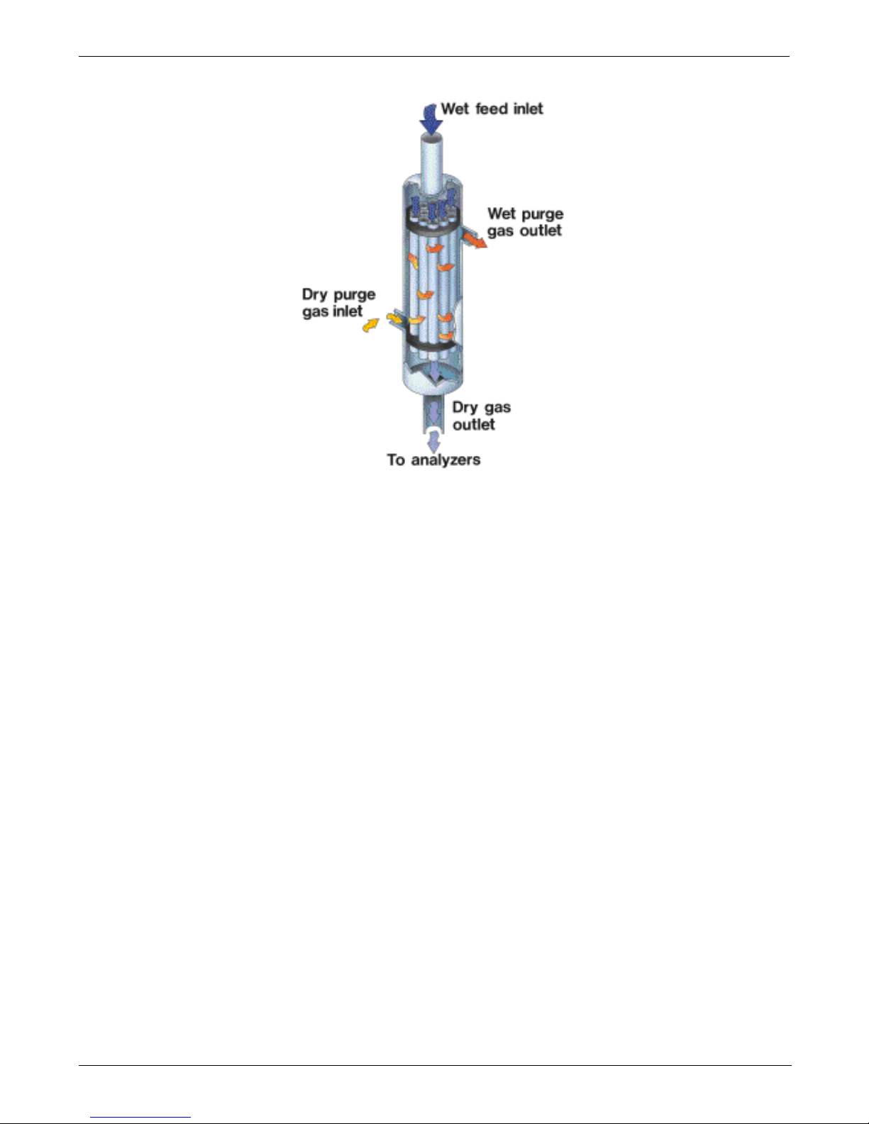
Principles of Operation Teledyne API - T300U Addendum to T300/T300M Manual
62 06867D DCN7970
Figure 8-3: Semi-Permeable Membrane Drying Process
Page 65

Teledyne API - T300U Addendum to T300/T300M Manual Principles of Operation
06867D DCN7970 63
The dryer consists of a bundle of 0.030" O.D. Nafion tubes housed within a single
large tube shell. Sample gas flows within the Nafion tubes while water vapor absorbs
into the tubular membrane walls and is removed. Moisture permeating the tubing is
carried away by a dry purge gas within the shell that flows countercurrent to the sample
gas.
This process is called per-evaporation and is driven by the humidity gradient between
the inner and outer tubes as well as the flow rates and pressure difference between inner
and outer tubing. Unlike micro-porous membrane permeation, which transfers water
through a relatively slow diffusion process, per-evaporation is a simple kinetic reaction.
Therefore, the drying process occurs quickly, typically within milliseconds.
The first step in this process is a chemical reaction between the molecules of the Nafion
®
material and water, other chemical components of the gases to be dried are usually
unaffected. The chemical reaction is based on hydrogen bonds between the water
molecule and the Nafion material. Other small polar gases that are capable of hydrogen
bonds can be absorbed this way, too, such as ammonia (NH
3
) and some low molecular
amines. The gas of interest to the T300U, CO, does not get absorbed and passes though
the dryer unaltered.
To provide a dry purge gas for the outer side of the Naf ion tube, the T300U returns some
of the dried air from the inner tube to the outer tube (see Figure 3-3).
When the analyzer is first started, or if the instrument is turned on after having been off
for more than 30 minutes, the humidity gradient between the inner and outer tubes is not
very large and the dryer’s efficiency is low at first but improves as this cycle reduces the
moisture in the sample gas and settles at a minimum humidity.
The dryer used in the T300U is capable of adequately drying ambient air to a dew point
of ≤ -6˚C (~4000 ppm residual H
2
O) at the flow rate of the analyzer.
Page 66

Principles of Operation Teledyne API - T300U Addendum to T300/T300M Manual
64 06867D DCN7970
8.3. ELECTRONIC OPERATION
8.3.1. OVERVIEW
The information found in Section 13.4 of the T300/T300M Operators Manual (P/N
06864) is applicable to the T300U with the following exception(s):
• This figure replaces Figure 13-9 of the T300/T300M Operators Manual.
Page 67
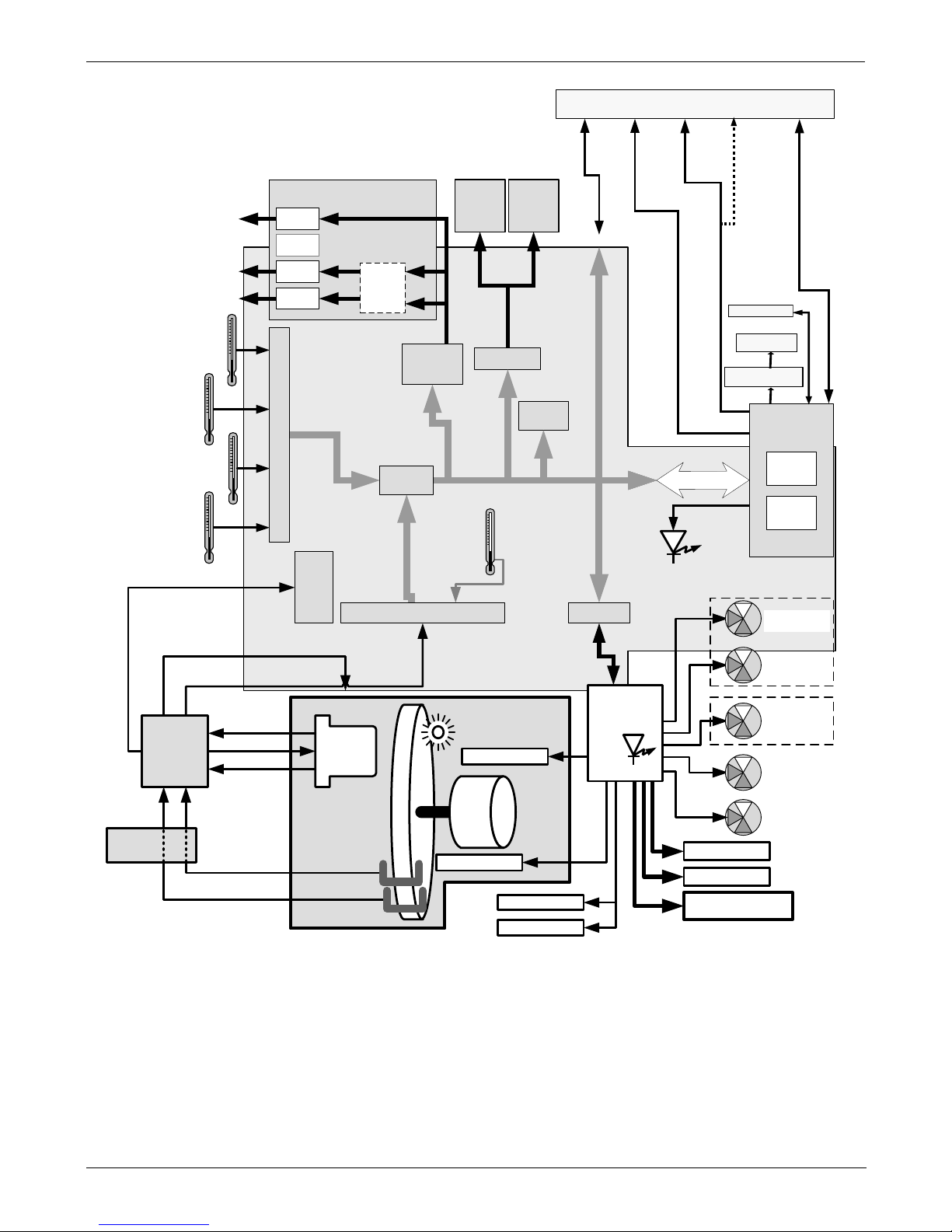
Teledyne API - T300U Addendum to T300/T300M Manual Principles of Operation
06867D DCN7970 65
INTERNAL PUMP
Analog Outputs
Aout 1
Aout 4
Analog
Outputs
(D/A)
External
Digital I/O
Power Up
Circuit
PC 104 Bus
PC 104
CPU Card
Disk on
Module
Flash
Chip
Aout 3
Aout 2
TEST CHANNEL OUTPUT
Status
Outputs
1 - 8
Control
Outputs
1 – 6
CPU
Status
LED
I
2
C Bus
Wheel Heater
Sensor Inputs
Chassis
Temperature
A
/D
Converter
SPAN Valve
(Optional)
Shutoff Valve
(Optional)
ZERO Valve
(
Optional
)
Sample Gas
Temperature
Optical Bench
Temperature
CO Concentration
RANGE2
CO Concentration
RANGE1
Measure/
Reference
Valve
MOTHERBOARD
AutoReference
Valve
Oven
Temperature
GFC Wheel
Temperature
Thermistor Interface
Internal
Digital I/O
SYNC
DEMOD
IR Photo-
detector
Bench Heater
Oven Heater
Oven Heater
Oven Fan
Oven Fan
Schmidt
Trigger
SENSOR STATUS &
CONTROL
CO MEAS
CO REF
Segment Sensor
M/R Sensor
PHT
Drive
TEC
Control
Detector
Output
Optional
mA
Output
RELAY
PCA
I2C
Status
LED
GFC WHEEL
GFC
Motor
IR SOURCE
(I2C Bus)
Ethernet
USB COM
port
COM1
(RS-232 only)
COM
2 (RS-232 or RS-485)
or USB
Touchscreen
Display
LVDS
Transmitter Board
COM
2
Female
RS232
Male
ANALOG
IN
Figure 8-4: T300U Electronic Overview Block Diagram
8.3.2. THE RELAY PCA
The information found in Section 13.4.4 of the T300/T300M Operators Manual (P/N
06864) is applicable to the T300U with the following exception(s):
Page 68

Principles of Operation Teledyne API - T300U Addendum to T300/T300M Manual
66 06867D DCN7970
8.3.2.1. Temperature Control of the Convection Oven
The information found in Section 13.4.4.1 of the T300/T300M Operators Manual (P/N
06864) is applicable to the T300U with the following exception(s):
• There are two heaters attached to either side of the optical bench (see Figure 3-1)
that radiate heat into the insulated, oven area of the analyzer. Each heater has a
fan attached to it that circulates the heated air throughout the oven airspace.
• The CPU senses the temperature level form different places inside the oven area
and determines the overall temperature of the oven. Eventually, all of the
components within the oven area will stabilize at the same temperature. This
usually takes about 24 hours after the instrument is turned ON.
• A separate fan blows directly on the A-to-D conversion circuitry of the motherboard
to more keep it at the same temperature as the oven airspace in order to eliminate
any temperature-coefficient related offset.
CONVECTION OVEN AREA
Oven Heater
Oven Heater
Wheel Heater
Bench Heater
GFC WHEEL
GFC
Motor
IR SOURCE
Thermistor(s):
• Sample Gas Temp
• Bench Temp
• GFC Wheel Temp
• Oven Temp
RELAY PCA
MOTHER BOARD
A/D
Converter
(V/F)
CPU
Solid State
AC Relays
CIRCULATION FANS
Motherboard
Temp-Co Fan
Figure 8-5: T300U Heating Control Block Diagram
Page 69
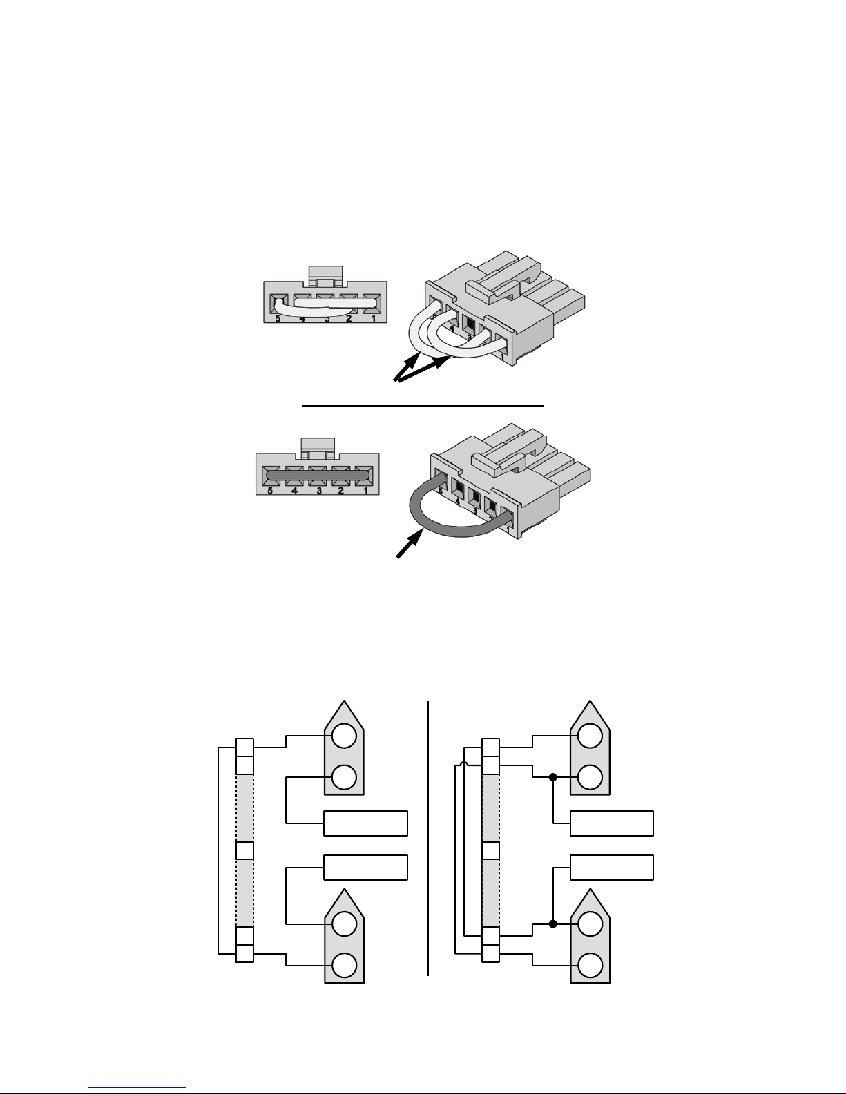
Teledyne API - T300U Addendum to T300/T300M Manual Principles of Operation
06867D DCN7970 67
8.3.2.2. Oven Heater AC Power Configuration
The two main heaters for the convection oven area of the T300U are AC heaters. A
jumper, located in line on the power connection between the relay PCA and the heaters,
set the heaters in one of two configurations:
• In parallel for 115 VAC operation, or;
• In series for 230 VAC operation.
Blue Jumper
115 VAC Configuration
White Jumpers
230 VAC Configuration
Figure 8-6: T300U Oven Heater Configuration Jumpers
220/230 VAC 110/115 VAC
1
2
1
2
AC High
Neutral
3
4
5
1
2
Configuration Plug (JP3)
Heater 1
(Inboard)
Heater 2
(outboard)
1
2
1
2
AC High
Neutral
3
4
5
1
2
Configuration Plug (JP3)
Heater 1
(Inboard)
Heater 2
(outboard)
Figure 8-7: T300U Oven Heater Configuration Circuit
Page 70

Principles of Operation Teledyne API - T300U Addendum to T300/T300M Manual
68 06867D DCN7970
8.3.2.3. Status LEDs
This information replaces that found in Sections 13.4.4.5 of the T300/T300M Operators
Manual.
• Eight LEDs, described in Table 8-2 are located on the analyzer’s relay board to
show the current status on the various control functions performed by the relay
board (see Figure 13-15 of the T300/T300M Operators Manual).
Table 8-2: Relay Board Status LED’s
LED
COLOR
FUNCTION
STATUS WHEN LIT
STATUS WHEN DARK
D1
RED Watchdog Circ uit
Cycles On/Off Every 3 Seconds under direct control of the
analyzer’s CPU.
D2
YELLOW Wheel Heater HEATING NOT HEATING
D3
YELLOW Bench Heater HEATING NOT HEATING
D4
YELLOW
Oven Heaters
HEATING
NOT HEATING
D5
GREEN
Sample/Cal Gas
Valve Option
Valve Open to
CAL GAS FLOW
Valve Open to
SAMPLE GAS FLOW
D6
GREEN
Zero/Span Gas
Valve Option
Valve Open to
SPAN GAS FLOW
Valve Open to
ZERO GAS FLOW
D7
GREEN
Shutoff Valve
Option
Valve Open to
CAL GAS FLOW
Valve CLOSED to
CAL GAS FLOW
D8
GREEN IR SOURCE Source ON Source OFF
8.3.3. MOTHERBOARD
The information found in Section 13.4.5 of the T300/T300M Operators Manual (P/N
06864) is applicable to the T300U with the following additions:
8.3.3.1. A to D Conversion
Because the T300U has much higher resolution and sensitivity than the T300/T300M,
the possibility that temperature-coefficient related drift could occur in the 10.3.3.1. A to
D conversion circuitry if there were a significant difference in temperature between the
converter and the surrounding airspace. To prevent this, a fan direct heated air directly
onto the A to D converter area of the motherboard to ensure that it is as close as possible
to the current temperature of the oven area.
8.3.3.2. Sensor Inputs
OVEN TEMPERATURE SENSOR
A thermistor is located in the center of the insulated oven area (see Figure 3-1). It
measures the analyzer’s inside temperature. This information is stored by the CPU and
can be viewed by the user for troubleshooting purposes via the front panel display by
selecting the test function OVEN TEMP or reported via the instruments TEST
CHANNEL analog output (A4) by setting the output function also named OVEN
TEMP.
Page 71
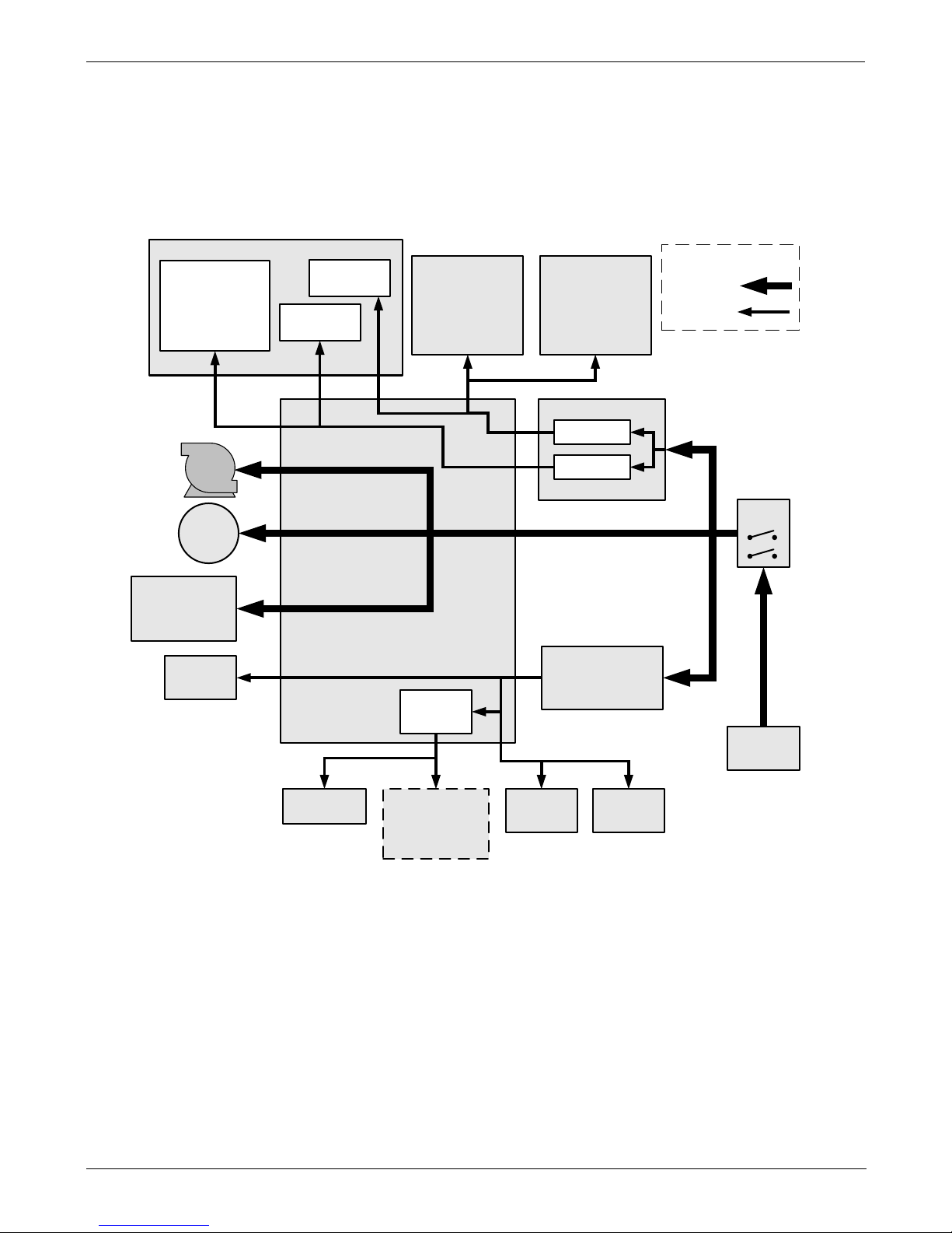
Teledyne API - T300U Addendum to T300/T300M Manual Principles of Operation
06867D DCN7970 69
8.3.4. POWER DISTRIBUTION
The information found in Section 13.4.7 of the T300/T300M Operators Manual (P/N
06864) is applicable to the T300U with the following exception(s):
• The following figure replaces Figure 13-16 of the T300/T300M Operators Manual
(P/N 06864).
GFC
Wheel
Motor
SENSOR SUITES
LOGIC DEVICES
(e.g. CPU and its
peripheral devices,
I
2
C bus,
Sync Demod PCA,
Motherboard, etc.)
RELAY PCA
ON / OFF
SWITCH
PS 2
(+12 VDC)
OPTIONAL
VALVES
(e.g. Sample/Cal,
Zero/Spans, etc.)
A-REF VALVE
COOLING
FAN
PUMP
AC HEATERS
· Bench Heater
· GFC Wheel Heater
· Oven Heaters
PS 1
ANALOG SENSORS
· IR detector
sensors
· Temp Sensors,
· Flow Sensors,
· Pressure Sensors
Pre-Amplifiers
& Amplifiers
Sensor Control
& I/O Logic
Solenoid
Drivers
KEY
AC POWER
DC POWER
AC
POWER IN
+5 VDC
±15 VDC
IR Source
P/S
OVEN
FAN(S)
OPTIONAL
DEVICES
(e.g. mA Outputs,
Multidrop PCA, etc.)
Figure 8-8: T300U Distribution Block Diagram
.
Page 72

Principles of Operation Teledyne API - T300U Addendum to T300/T300M Manual
70 06867D DCN7970
This page intentionally left blank.
Page 73

06867D DCN7970 71
9. TROUBLESHOO TI NG & SERVICE
9.1. GENERAL NOTES
CAUTION
THE OPERATIONS PRESENTED IN THIS SECTION MUST BE PERFORMED BY
QUALIFIED MAINTENANCE PERSONNEL ONLY.
PLEASE READ SECTION 14 OF THE T300/T300M MANUAL (P/N 06864) BEFORE
ATTEMP TI NG THE FO L LOWING TROUBLESHOOTING OR SERVICE PROCEDURES
WARNING - RISK OF ELECTRICAL SHOCK.
SOME OPERATIONS NEED TO BE CARRIED OUT WITH THE ANALYZER OPEN AND
RUNNING.
EXERCISE CAUTION TO AVOID ELECTRICAL SHOCKS AND ELECTROSTATIC OR
MECHANICAL D AMAGE TO THE ANALYZER.
DO NOT DROP TOOLS INTO THE ANALYZER OR LEAVE THOSE AFTER YOUR
PROCEDURES.
DO NOT SHORTEN OR TOUCH ELECTRIC CONNECTIONS WITH METALLIC TOOLS
WHILE OPERATING INSIDE THE ANALYZER.
USE COMMON SENSE WHEN OPERATING INSIDE A RUNNING ANALYZER.
The information found in Section 12 of the T300/T300M Operators Manual (P/N 06864)
is applicable to the T300U with the exceptions below.
CAUTION
ALWAYS ALLOW THE T300U TO OPERATE FOR AT LEAST 24 HOURS AFTER ALL
REPAIRS HAVE BEEN FINISHED AND THE INSTRUMENT’S CASE IS CLOSED.
AT THE END OF THIS 24-HOUR STA BILIZATION PERIOD MANUALLY INITIATE AN AREF MEASUREMENT (SEE SECTION 4.4.2)
Page 74

Troubleshooting & Service Teledyne API - T300U Addendum to T300/T300M Manual
72 06867D DCN7970
9.2. FAULT DIAGNOSIS WITH WARNING MESSAGES
The following Table replaces Table 13-1 of the T300/T300M Operators Manual.
Table 9-1: Warning Messages - Indicated Failures
WARNING
MESSAGE
FAULT CONDITION POSSIBLE CAUSES
BENCH TEMP
WARNING
The optical bench temp is
controlled at 48 ± 2
°
C.
Bad bench heater
Bad bench temperature sensor
Bad relay controlling the bench heater
Entire relay board is malfunctioning
BOX TEMP
WARNING
Box Temp is
< 5
°
C or > 48 °C.
NOTE: For T300U‘s operating for at least 2 hours, the box
temperature typically should be the same as the oven
temperature (46ºC).
Stopped motherboard stabilization fan
Stopped oven heater fan (there are two)
Failed oven heater (s)
Failed oven fan(s)
Failed oven temperature sensor
Failed relay controlling the one of the oven heaters
Failed relay board
CANNOT DYN
SPAN
Dynamic Span operation failed
Measured concentration value is too high or low.
Concentration slope value to high or too low
CANNOT DYN
ZERO
Dynamic Zero operation failed
Measured concentration value is too high.
Concentration offset value to high.
CONFIG
INITIALIZED
Configuration and Calibration data
reset to original Factory state.
Failed disk on module
User erased data
DATA INITIALIZED
Data Storage in DAS was erased
Failed disk on module
User cleared data
PHOTO TEMP
WARNING
PHT DRIVE is
>4800 mVDC
Failed IR photo-detector
Failed sync/demod board
IR photo-detector improperly attached to the sample chamber
Bench temp too high.
OVEN TEMP
WARNING
The temperature of the insulated
convection oven area of the
analyzer is outside of the specified
limits.
Oven temperature outside of specified range
Failed oven heater (s)
Failed oven fan(s)
Failed oven temperature sensor
Relay controlling the one of the oven heater
Failed relay board
REAR BOARD NOT
DET
Motherboard not detected on
power up.
Warning only appears on serial I/O com port(s)
Front panel display will be frozen, blank or will not respond.
Massive failure of motherboard
RELAY BOARD
WARN
The CPU cannot communicate with
the Relay Board.
I2C buss failure
Failed relay board
Loose connectors/wiring
SAMPLE FLOW
WARN
Sample flow rate is
<1400 cm
3
/min
or
> 2200 cm
3
/min.
Failed sample pump
Blocked sample inlet/gas line
Dirty particulate filter
Leak downstream of critical flow orifice
Failed flow sensor/circuitry
Page 75

Teledyne API - T300U Addendum to T300/T300M Manual Troubleshooting & Service
06867D DCN7970 73
WARNING
MESSAGE
FAULT CONDITION POSSIBLE CAUSES
SAMPLE PRES
WARN
Sample Pressure is
<10 in-Hg or > 35 in-Hg
Normally 29.92 in-Hg at sea level
decreasing at 1 in-Hg per 1000 ft of
altitude (with no flow – pump
disconnected).
If sample pressure is < 10 in-hg:
o Blocked particulate filter
o Blocked sample inlet/gas line
o Failed pressure sensor/circuitry
If sample pressure is > 35 in-hg:
o Pressurized sample gas. Install vent
o Blocked vent line on pressurized sample/zero/span gas
supply
o Bad pressure sensor/circuitry
SAMPLE TEMP
WARN
Sample temperature is < 10
o
C or >
100
o
C.
Ambient temperature outside of specified range
Failed bench heater
Failed bench temperature sensor
Relay controlling the bench heater
Failed relay board
SOURCE
WARNING
Occurs when CO Ref is <1250
mVDC or >4950 mVDC.
Either of these conditions will result
in an invalid M/R ratio.
GFC wheel stopped
Failed sync/demod board
If status LED’s on the sync/demod board ARE flashing, the
cause is most likely a failed:
o IR source
o Relay board
o IR photo-detector
SYSTEM RESET
The computer has rebooted.
This message occurs at power on. If you have not cycled the
power on your instrument:
o Failed +5 VDC power,
o Fatal error caused software to restart
o Loose connector/wiring
WHEEL TEMP
WARNING
The filter wheel temperature is
outside specified limites.
(The wheel temperature is typically
controlled at 62 ± 2
°
C).
Blocked cooling vents below GFC Assembly. (Make sure that
adequate clear space beneath the analyzer).
Analyzer’s top cover removed
Wheel heater
Wheel temperature sensor
Relay controlling the wheel heater
Entire relay board
Page 76

Troubleshooting & Service Teledyne API - T300U Addendum to T300/T300M Manual
74 06867D DCN7970
9.2.1. FAULT DIAGNOSIS WITH TEST FUNCTIO NS
The following table supersedes Table 12.2 of the T300/T300M Operators Manual (P/N
06864).
Table 9-2: Test Functions - Indicated Failures
TEST
FUNCTIONS
(As Displayed)
INDICATED FAILURE(S)
TIME
Time of day clock is too fast or slow
To adjust, see Section 5.6 of the T300/T300M Operators Manual (P/N 06864).
Battery in clock chip on CPU board may be dead.
RANGE
Incorrectly configured measurement range(s) could cause response problems with a Data logger or chart
recorder attached to one of the analog output.
If the Range selected is too small, the recording device will over range.
If the Range is too big, the device will show minimal or no apparent change in readings.
STABIL
Indicates noise level of instrument or CO concentration of sample gas (See Section 12.4.2 of the T300/T300M
Operators Manual for causes).
CO MEAS
&
CO REF
If the value displayed is too high the IR Source has become brighter. Adjust the variable gain potentiometer on
the sync/demod board (See Section 12.5.7.1 of the T300/T300M Operators Manual)
If the value displayed is too low or constantly changing and the CO REF is OK:
o Failed multiplexer on the mother board
o Failed sync/demod board
o Loose connector or wiring on sync/demod board
If the value displayed is too low or constantly changing and the CO REF is BAD:
o GFC wheel stopped or rotation is too slow
o Failed sync/demod board IR source
o Failed IR source
o Failed relay board
o Failed
I2C bus
o Failed IR photo-detector
MR RATIO
When the analyzer is sampling zero air and the ratio is too low:
o The reference cell of the GFC wheel is contaminated or leaki ng.
o The alignment between the GFC wheel and the segment sensor, the M/R sensor or both is incorrect.
o Failed sync/demod board
When the analyzer is sampling zero air and the ratio is too high:
o Zero air is contaminated
o Failed IR photo-detector
PRES
See Table 9-1 for SAMPLE PRES WARN
SAMPLE FL
Check for gas flow problems. (See Section 12.2 of the T300/T300M Operators Manual)
SAMPLE
TEMP
SAMPLE TEMP should be close to BENCH TEMP. Temperatures outside of the specified range or oscillating
temperatures are cause for concern
BENCH TEMP
Bench temp control improves instrument noise, stability and drift. Temperatures outside of the specified range
or oscillating temperatures are cause for concern. See Table 9-1 for BENCH TEMP WARNING
WHEEL TEMP
Wheel temp control improves instrument noise, stability and drift. Outside of set point or oscillating
temperatures are causes for concern. See Table 9-1 for WHEEL TEMP WARNING
BOX TEMP
If the box temperature is out of range:
o Check the motherboard stabilization fan (see Figure 3-1).
o See Table 9-1 for BOX TEMP WARNING.
OVEN TEMP
If the oven is temperature is out of range, check both of the oven heater fans in the power supply module.
Areas to the side and rear of instrument should allow adequate ventilation.
o Check the both of the oven fans (see Figure 3-1).
o Check both of the oven heaters.
See Table 9-1 for OVEN TEMP WARNING.
Page 77

Teledyne API - T300U Addendum to T300/T300M Manual Troubleshooting & Service
06867D DCN7970 75
TEST
FUNCTIONS
(As Displayed)
INDICATED FAILURE(S)
PHT DRIVE
If this drive voltage is out of range it may indicate one of several problems:
- A poor mechanical connection between the various components in inside the detector housing
- An electronic failure of the IR Photo-Detector’s built-in cooling circuitry, or;
- A temperature problem inside the analyzer chassis. In this case other temperature warnings would also be
active such as OVEN TEMP WARNING, BENCH TEMP WARNING or BOX TEMP WARNING.
SLOPE
Values outside range indicate
Contamination of the zero air or span gas supply
Instrum ent is miscalibrated
Blocked gas flow
Contaminated or leaking GFC wheel (either chamber)
Faulty IR photo-detector
Faulty sample faulty IR photo-detector pressure sensor (P1) or circuitry
Invalid M/R ratio (see above)
Bad/incorrect span gas concentration due.
OFFSET
Values outside range indicate
Contamination of the zero air supply
Contaminated or leaking GFC wheel (either chamber)
Faulty IR photo-detector
Page 78

Troubleshooting & Service Teledyne API - T300U Addendum to T300/T300M Manual
76 06867D DCN7970
9.2.2. RELAY BOARD STATUS LEDs
The information found in Section 12.1.4.3 of the T300/T300M Operators Manual (P/N
06864) is applicable to the T300U with the following exception:
• The following table replaces Table 12-5 of the T300/T300M Operators Manual.
Table 9-3: Relay Board Status LED Failure Indications
LED FUNCTION
SIGNAL I/O PARAMETER
DIAGNOSTIC TECHNIQUE
ACTIVATED BY VIEW RESULT
D2
Yellow
WHEEL
HEATER
WHEEL_HEATER WHEEL_TEMP
Voltage displayed should change. If not:
Failed Heater
Faulty Temperature Sensor
Failed AC Relay
Faulty Connectors/Wiring
D3
Yellow
BENCH
HEATER
BENCH_HEATER BENCH_TEMP
Voltage displayed should change. If not:
Failed Heater
Faulty Temperature Sensor
Failed AC Relay
Faulty Connectors/Wiring
D4
Yellow
OVEN
HEATERS
OVEN_HEATER OVEN_TEMP
Voltage displayed should change. If not:
Failed Oven Heater(s)
Failed Oven Fans(s)
Faulty Oven Temperature Sensor
Failed AC Relay
Faulty Connectors/Wiring
D5
Green
SAMPLE/CAL
GAS VALVE
OPTION
CAL_VALVE
N/A
Sample/Cal Valve should audibly change states. If
not:
Failed Valve
Failed Relay Drive IC on Relay Board
Failed Relay Board
Faulty +12 VDC Supply (PS2)
Faulty Connectors/Wiring
D6
Green
ZERO/SPAN
GAS VALVE
OPTION
SPAN_VALVE
N/A
Zero/Span Valve should audibly change states. If
not:
Failed Valve
Failed Relay Drive IC on Relay Board
Failed Relay Board
Faulty +12 VDC Supply (PS2)
Faulty Connectors/Wiring
D7
Green
SHUTOFF
VALVE OPTION
SHUTOFF_VALVE
N/A
Shutoff Valve should audibly change states. If not:
Failed Valve
Failed Relay Drive IC on Relay Board
Failed Relay Board
Faulty +12 VDC Supply (PS2)
Faulty Connectors/Wiring
D8
Green
IR SOURCE
IR_SOURCE CO_MEASURE
Voltage displayed should change. If not:
Failed I R Source
Faulty +12 VDC Supply (PS2)
Failed Relay Board
Failed IR Photo-Detector
Failed Sync/Demod Board
Faulty Connectors/Wiring
Page 79

Teledyne API - T300U Addendum to T300/T300M Manual Troubleshooting & Service
06867D DCN7970 77
9.3. GAS FLOW PROBLEMS
Along with the information found in Section 12.2 of the T300/T300M Operators Manual
(P/N 06864), also be aware that problems with the flow of gas through the Nafion
dryer
could also be a cause of pressure or flow problems through the T300U. Poor gas flow or
leaks related to the dryer can also cause it to not dry the sample gas efficiently allowing
extra H
2
O to interfere with the analyzer’s CO measurements.
In addition to the checks described in the T300/T300M Operators Manual
• Check for blockages in the dryer.
• Check for leakage in and around the dryer and its fixtures (both the wet gas stream
and the purge gas inlets/outlets.
If it becomes necessary to replace the Nafion dryer, contact Teledyne Instruments’
Customer Service (see Section 9.6) for parts and instructions.
9.4. OTHER PERFORMANCE PROBLEMS
The information found in Section 12.4 of the T300/T300M Operators Manual (P/N
06864) is applicable to the T300U with the following addition.
9.4.1. UNEXPLAINED DRIFT
Because the T300U makes higher resolution CO measurements than the T300/T300M,
subtle issues with certain subsystems that would be unimportant for the T300/T300M
can affect its accuracy: The most common of these are:
• Temperature Coefficient issues related to the motherboard’s A-to-D converter
• Age related changes to some of the optical bench components (e.g. the mirrors, the
IR source, the IR detector, etc.)
• Ambient changes in the condition of the instrument or the sample gas.
If a drift problem exists and calibrating the instruments zero and span points does not
correct the problem or there is no obvious component failure, perform the following
operations in order:
1. Let the analyzer run uninterrupted for at least 24 hours.
• This will ensure that the entire oven area and all of the components therein
have reached an equal and stabile temperature.
2. Perform an Internal A-to-D Converter calibration (see Section 5.9.3.10 of the
T300/T300M Operators Manual).
• This should solve any issues related to the A/D converter.
3. Perform a Dark Calibration of the Optical Bench (see Section 9.6.1 of the
T300/T300M Operators Manual).
• This should account for any issues related to changes in the optical bench
components.
4. Manually initiate an A-REF cycle (see Section 4.4.2).
• This should account for any issues related to changes in the ambient conditions
of the sample gas.
Page 80

Troubleshooting & Service Teledyne API - T300U Addendum to T300/T300M Manual
78 06867D DCN7970
9.5. SUBSYSTEM CHECKOUT
9.5.1. RELAY BOARD
The information found in Section 12.5.6 of the T300/T300M Operators Manual (P/N
06864) is applicable to the T300U with the following exception:
• The following table replaces Table 12-8 of the T300/T300M Operators Manual.
Table 9-4: Relay Board Control Devices
FUNCTION
CONTROL
DEVICE
IN SOCKET
Wheel Heater K1 Yes
Bench Heater K2 Yes
OVEN HEATER K3 YES
IZS Valves U4 Yes
IR Source Drive U5 No
9.5.2. MOTHERBOARD
9.5.2.1. A/D Functions
The T300U makes higher resolution CO measurements than the T300/T300M means
that it is susceptible to temperature coefficient issues related to the motherboard’s A-toD converter that could occur if the temperature of the motherboard differs significantly
from that of the rest of the analyzer’s oven area.
• Compare the values of the BOX TEMP & OVEN TEMP test functions. If they are
significantly different check the function of the:
• Oven theaters.
• The oven heater fans.
• The motherboard stabilization fan.
• The relays controlling the oven heaters.
• No abnormal blockages to airflow inside the oven area exist.
Page 81

Teledyne API - T300U Addendum to T300/T300M Manual Troubleshooting & Service
9.6. TECHNICAL ASSISTANCE
If this addendum and its trouble-shooting / repair sections do not solve your problems,
technical assistance may be obtained from:
Teledyne API
Technical Support
9970 Carroll Canyon Rd
San Diego, CA 92131-1106
Phone: +1 858 657 9800 or 1-800 324 5190
Fax: +1 858 657 9816
Email: api-techsupport@teledyne.com.
Before you contact Technical Support, fill out the Product Warranty
Repair/Questionnaire on our website at http://www.teledyne-api.com under Service &
Support.
06867D DCN7970 79
Page 82

Troubleshooting & Service Teledyne API - T300U Addendum to T300/T300M Manual
80 06867D DCN7970
This page intentionally left blank.
Page 83

06867D DCN7970
APPENDIX A – T300U/M300EU Version Specific Software Menu
Trees
(05924B DCN5871)
This Appendix to the T300U and M300EU Addenda contains only the software menu
trees unique to the T300U and the M300EU models. For the additional software
documentation, please refer to Appendix A in the related operation manual:
T300U - T300/T300M operation manual, PN 06864
M300EU - M300E/EM operation manual, PN 04288
Please note that in those appendices not all variables or parameters apply to the T300U
or M300EU, such as the O
or CO2 options, which are not available in these units.
2
A-1
Page 84

APPENDIX A: T300U, M300EU Software Menu Trees, Revision L.8 Teledyne API - T300U, M300EU 05924B DCN5871
06867D DCN7970
This page intentionally left blank.
A-2
Page 85

Teledyne API - T300U, M300EU 05924B DCN5871 APPENDIX A: T300U, M300EU Software Menu Trees, Revision L.8
A-3
APPENDIX A: T300U, M300EU Software Menu Trees, Revision L.8
RANGE=[Value] PPM
RANGE1=[Value] PPM
2
RANGE2=[Value] PPM
2
STABIL=[Value] PPM
CO MEAS=[Value] MV
CO REF=[Value] MV
MR RATIO=[Value]
AZERO RATIO=[Value]
PRES=[Value] IN-HG-A
SAMPLE FL=[Value] CC/M
BENCH TEMP=[Value] C
WHEEL TEMP=[Value] C
OVEN TEMP=[Value] C
PHT DRIVE=[Value] MV
SLOPE1=[Value]
SLOPE2=[Value]
OFFSEt=[Value]
OFFSET2=[Value]
TIME=[HH:MM:SS]
PRIMARY SETUP
MENU
SAMPLE
MSG
1
CALZ
3
CALS
3
CLR
1
SETUP
<TST TST>
CALTEST
1
DASCFG ACAL
4
CLKRANGE PASS MORE
SECONDARY
SETUP MENU
Press to
cycle
through the
active
warning
messages.
Press to
clear an
active
warning
messages.
DIAGCOMM VARS ALAR
5
LOW2HIGH
2
CONCZERO SPAN
LOW
2
HIGH
2
CONCSPAN
LOW
2
HIGH
2
1
Only appears when warning messages are active.
2
Only appears when the reporting ranges are set for either
DUAL or AUTO mode.
3
Only appears if analyzer is equipped with Zero/Span or IZS
valve options.
Figure A-1: Basic Sample Display Menu
06867D DCN7970
Page 86

APPENDIX A: T300U, M300EU Software Menu Trees, Revision L.8 Teledyne API - T300U, M300EU 05924B DCN5871
A-4
Figure A-2: Primary Setup Menu (Except DAS)
06867D DCN7970
Page 87

Teledyne API - T300U, M300EU 05924B DCN5871 APPENDIX A: T300U, M300EU Software Menu Trees, Revision L.8
A-5
Figure A-3: Primary Setup Menu
DAS Submenu
06867D DCN7970
Page 88

APPENDIX A: T300U, M300EU Software Menu Trees, Revision L.8 Teledyne API - T300U, M300EU 05924B DCN5871
A-6
SETUP
PASSDAS RNGE CLK
MORE
ACAL
CFG
SAMPLE
COMM
VARS
DIAG
EDIT
PRNTJUMPNEXTPREV
0) DAS_HOLD_OFF
1) CONC_PRECISION
2) DYN_ZERO
3) DYN_SPAN
4) CLOCK_ADJ
Go to DIAG Menu Tree
HESN
2
INET
1
ID
EDITSET><SET
COM1
COM2
1
TEST PORTBAUD RATEMODE
TEST
300
1200
2400
4800
9600
19200
38400
57600
115200
QUIET
COMPUTER
HESSEN PROTOCOL
E, 8, 1
E, 7, 1
RS-485
SECURITY
MULTIDROP PROTOCOL
ENABLE MODEM
ERROR CHECKING
XON/XOFF HANDSHAKE
HARDWARE HANDSHAKE
HARDWARE FIFO
COMMAND PROMPT
ON
OFF
ENTER PASSWORD: 818
ENTER PASSWORD: 818
ENTER PASSWORD: 818
EDITSET><SET
DHCP
ON OFF
INSTRUMENT IP
3
GATEWAY IP
3
SUBNET MASK
3
TCP PORT
4
HOSTNAME
5
1
M300E/EM, M300EU: Only appears if optional
Ethernet PCA is installed. When Ethernet PCA is
present COM2 submenu disappears.
2
Only appears if HESSEN PROTOCOL mode is ON
(See COM1 & COM2 – MODE submenu above).
3
INSTRUMENT IP, GATEWAY IP & SUBNET MASK are
only editable when DHCP is OFF.
4
M300E/EM, M300EU: Although TCP PORT is editable
regardless of the DHCP state, do not change the setting for
this property.
5
HOST NAME is only editable when DHCP is ON.
EDITEDIT
Go to
COMM / Hessen
Menu Tree
Figure A-4: Secondary Setup Menu
COMM and VARS Submenus
06867D DCN7970
Page 89
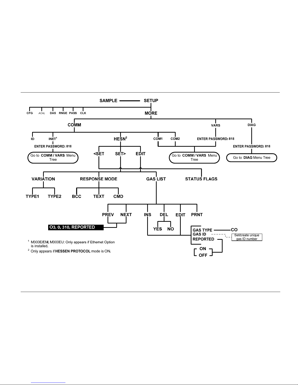
Teledyne API - T300U, M300EU 05924B DCN5871 APPENDIX A: T300U, M300EU Software Menu Trees, Revision L.8
A-7
Figure A-5: Secondary Setup Menu
Hessen Protocol Submenu
06867D DCN7970
Page 90
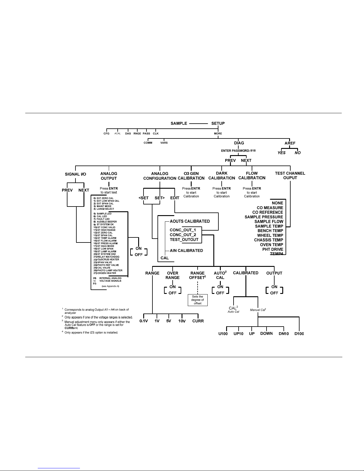
APPENDIX A: T300U, M300EU Software Menu Trees, Revision L.8 Teledyne API - T300U, M300EU 05924B DCN5871
A-8
Figure A-6: DIAG Menu
06867D DCN7970
Page 91
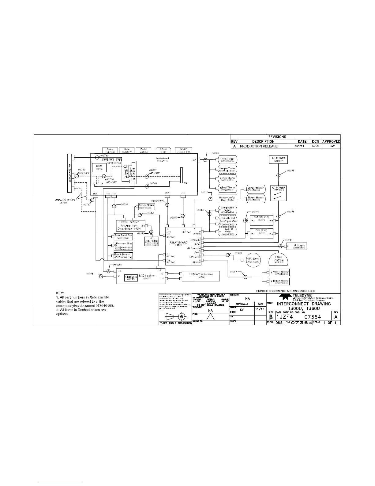
06867D DCN7970
B-1
Appendix B - Interconnect Diagram
 Loading...