

Page 1

USER MANUAL
MODEL 465H
OZONE MONITOR
©2007-2018 TAPI 06161H DCN7969
Teledyne API 21 August 2018
Teledyne API (TAPI)
9970 Carroll Canyon Road
San Diego, CA 92131-1106
Toll-Free: 800-324-5190
Phone: +1 858-657-9800
FAX: +1 858-657-9816
Email: api-sales@teledyne.com
Website: http://www.teledyne-api.com/
Page 2

Page 3
SAFETY MESSAGES
Important safety messages are provided throughout this manual for the purpose of avoiding
personal injury or instrument damage. Please read these messages carefully. Each safety
message is associated with a safety alert symbol and placed throughout this manual and inside the
instrument. The symbols with messages are defined as follows:
WARNING: Electrical Shock Hazard
HAZARD: Strong oxidizer
GENERAL WARNING/CAUTION: Read the accompanying message for
specific information.
CAUTION: Hot Surface Warning
Do Not Touch: Touching some parts of the instrument without protection or
proper tools could result in damage to the part(s) and/or the instrument.
Technician Symbol: All operations marked with this symbol are to be
performed by qualified maintenance personnel only.
Electrical Ground: This symbol inside the instrument marks the central
safety grounding point for the instrument.
CAUTION
GENERAL SAFETY HAZARD
This instrument should only be used for the purpose and in the
manner described in this manual. If you use it in a manner other
than that for which it was intended, unpredictable behavior could
ensue with possible hazardous consequences.
NEVER use any gas analyzer to sample combustible gas(es).
06161H DCN7969 Teledyne API Model 465H O3 Monitor User Manual i
Page 4
CONSIGNES DE SÉCURITÉ
Des consignes de sécurité importantes sont fournies tout au long du présent manuel dans
le but d’éviter des blessures corporelles ou d’endommager les instruments. Veuillez lire
attentivement ces consignes. Chaque consigne de sécurité est représentée par un
pictogramme d’alerte de sécurité; ces pictogrammes se retrouvent dans ce manuel et à
l’intérieur des instruments. Les symboles correspondent aux consignes suivantes :
AVERTISSEMENT : Risque de choc électrique
DANGER : Oxydant puissant
AVERTISSEMENT GÉNÉRAL / MISE EN GARDE : Lire la consigne
complémentaire pour des renseignements spécifiques
MISE EN GARDE : Surface chaude
Ne pas toucher : Toucher à certaines parties de l’instrument sans
protection ou sans les outils appropriés pourrait entraîner des dommages
aux pièces ou à l’instrument.
Pictogramme « technicien » : Toutes les opérations portant ce symbole
doivent être effectuées uniquement par du personnel de maintenance
qualifié.
Mise à la terre : Ce symbole à l’intérieur de l’instrument détermine le
point central de la mise à la terre sécuritaire de l’instrument.
MISE EN GARDE
Cet instrument doit être utilisé aux fins décrites et de la manière décrite dans
ce manuel. Si vous utilisez cet instrument d’une autre manière que celle pour
laquelle il a été prévu, l’instrument pourrait se comporter de façon
imprévisible et entraîner des conséquences dangereuses.
NE JAMAIS utiliser un analyseur de gaz pour échantillonner des gaz
combustibles!
ii Teledyne API Model 465H O3 Monitor User Manual 06161H DCN7969
Page 5
WARRANTY
WARRANTY POLICY (02024J)
Teledyne API (TAPI), a business unit of Teledyne Instruments, Inc.,
provides that:
Prior to shipment, TAPI equipment is thoroughly inspected and tested.
Should equipment failure occur, TAPI assures its customers that prompt
service and support will be available. (For the instrument-specific warranty
period, please refer to the “Limited Warranty” section in the Terms and
Conditions of Sale on our website at the following link:
http://www.teledyne-api.com/terms_and_conditions.asp).
COVERAGE
After the warranty period and throughout the equipment lifetime, TAPI
stands ready to provide on-site or in-plant service at reasonable rates similar
to those of other manufacturers in the industry. All maintenance and the first
level of field troubleshooting are to be performed by the customer.
NON-TAPI MANUFACTURED EQUIPMENT
Equipment provided but not manufactured by TAPI is warranted and will be
repaired to the extent and according to the current terms and conditions of
the respective equipment manufacturer’s warranty.
Product Return
Failure to comply with proper anti-Electro-Static Discharge (ESD) handling
and packing instructions and Return Merchandise Authorization (RMA)
procedures when returning parts for repair or calibration may void your
warranty. For anti-ESD handling and packing instructions please refer to the
manual, Fundamentals of ESD, PN 04786, in its “Packing Components for
Return to Teledyne API’s Customer Service” section. The manual can be
downloaded from our website at http://www.teledyne-api.com. RMA
procedures can also be found on our website.
All units or components returned to Teledyne API should be properly
packed for handling and returned freight prepaid to the nearest designated
Service Center. After the repair, the equipment will be returned, freight
prepaid.
The complete Terms and Conditions of Sale can be reviewed at
http://www.teledyne-api.com/terms_and_conditions.asp
CAUTION – Avoid Warranty Invalidation
06161H DCN7969 Teledyne API Model 465H O3 Monitor User Manual iii
Page 6

THIS PAGE IS INTENTIONALLY LEFT BLANK
iv Teledyne API Model 465H O3 Monitor User Manual 06161H DCN7969
Page 7

TABLE OF CONTENTS
1. INTRODUCTION......................................................................................................... 8
2. SPECIFICATIONS AND AGENCY APPROVALS ................................................. 9
2.1. SPECIFICATIONS ................................................................................................................................... 9
2.2. APPROVALS ........................................................................................................................................ 10
2.2.1. Safety ....................................................................................................................................... 10
2.2.2. EMC ........................................................................................................................................ 10
2.2.3. Other Type Certifications ....................................................................................................... 10
3. PRINCIPLE OF OPERATION ................................................................................. 11
4. GETTING STARTED ................................................................................................ 13
4.1. MECHANICAL INSTALLATION (FOR MONITORS IN NEMA 4X ENCLOSURES) ..................................... 13
4.1.1. Ventilation Clearance ............................................................................................................. 13
4.2. MECHANICAL INSTALLATION (19” RACK VERSION) ........................................................................... 14
4.2.1. Ventilation Clearance ............................................................................................................. 14
4.3. AC POWER CONNECTION (FOR MONITORS IN NEMA 4X ENCLOSURE) ............................................. 15
4.3.1. Wiring Requirements for NEMA Enclosures .......................................................................... 15
4.3.2. Wiring Instructions ................................................................................................................. 15
4.4. PNEUMATIC CONNECTIONS ................................................................................................................ 17
4.4.1. Installing Flow Control Assemblies ........................................................................................ 18
4.4.2. Ozone Inlet Connection ........................................................................................................... 19
4.4.3. Zero Gas Connection .............................................................................................................. 19
4.4.4. Exhaust Connection ................................................................................................................ 19
4.5. ELECTRICAL I/O CONNECTIONS ......................................................................................................... 21
4.5.1. Location of I/O Connectors in the NEMA Configuration ....................................................... 21
4.5.2. Analog Output ......................................................................................................................... 22
4.5.3. Status Outputs ......................................................................................................................... 22
4.5.4. Hi-Current Relay Outputs ....................................................................................................... 23
4.5.5. Digital Serial Interfaces .......................................................................................................... 24
5. FREQUENTLY ASKED QUESTIONS .................................................................... 25
6. HARDWARE AND SOFTWARE OPTIONS ............................................................... 26
6.1. RACK MOUNT SLIDES ......................................................................................................................... 26
6.2. ETHERNET (MODBUS
®
TCP/IP) ....................................................................................................... 26
7. OPERATION .............................................................................................................. 27
7.1. FRONT PANEL OVERVIEW ................................................................................................................... 27
7.1.1. Ozone Concentration Display ................................................................................................. 27
7.1.2. Menu Navigation Keypad ....................................................................................................... 27
7.1.3. Concentration Alarm Status/Reset .......................................................................................... 28
7.1.4. Status LED’s ........................................................................................................................... 28
7.2. FRONT PANEL MENUS ........................................................................................................................ 29
7.2.1. Menu Navigation Basics ......................................................................................................... 29
7.2.2. Editing Numeric Values .......................................................................................................... 29
7.2.3. SETUP-ALARM Menu ............................................................................................................ 32
7.2.4. SETUP-VARS Menu ................................................................................................................ 33
7.2.5. DIAG Menu ............................................................................................................................. 34
7.2.6. VIEW Menu ............................................................................................................................. 37
7.2.7. CONFIG Menu ....................................................................................................................... 38
7.3. ANALOG OUTPUT ............................................................................................................................... 38
06161H DCN7969 Teledyne API Model 465H O3 Monitor User Manual v
Page 8

8. DIGITAL COMMUNICATIONS ............................................................................. 39
8.1. DIGITAL COMMUNICATIONS OVERVIEW ............................................................................................ 39
8.2. CHANGING COM PORT HARDWARE CONFIGURATION ....................................................................... 39
8.3. RS-232 CONFIGURATION ................................................................................................................... 41
8.4. RS-485 CONFIGURATION ................................................................................................................... 42
8.5. ETHERNET CONFIGURATION .............................................................................................................. 43
8.5.1. Hardware Setup for Configuring the Ethernet Module .......................................................... 43
8.5.2. Verifying Network Hardware Connection .............................................................................. 43
8.5.3. Determining a Dynamically Assigned IP Address (DHCP Mode) ......................................... 44
8.5.4. Manually Assigning a Static IP Address ................................................................................ 44
8.6. MODBUS
8.6.1. Notes on MODBUS® registers ............................................................................................... 45
8.6.2. Real-Time Concentration and Status Registers (Read Only) ................................................. 46
8.6.3. Instrument Setup and Configuration Registers (Read / Write) ............................................... 46
®
REGISTER MAPS ............................................................................................................. 45
9. MAINTENANCE ........................................................................................................ 47
9.1. MAINTENANCE SCHEDULE ................................................................................................................. 47
9.2. INSTRUMENT LAYOUT ....................................................................................................................... 48
9.3. REPLACING INTERNAL PARTICULATE FILTER .................................................................................... 50
9.4. UV LAMP ADJUSTMENT .................................................................................................................... 51
9.5. UV LAMP REPLACEMENT .................................................................................................................. 52
9.6. REPLACING THE AUTO-ZERO VALVE ................................................................................................. 52
9.7. CONFIGURING THE ANALOG OUTPUT ................................................................................................ 53
9.8. CLEANING EXTERIOR SURFACES OF THE 465H .................................................................................. 54
9.9. BOOT LOADER OPERATION ................................................................................................................ 54
9.9.1. Boot Loader – Hardware Setup ............................................................................................. 54
9.9.2. Boot Loader – Software Setup ................................................................................................ 55
10. TROUBLESHOOTING ........................................................................................... 58
10.1. REFERENCE DRAWINGS ................................................................................................................... 58
10.1.1. Pneumatic Diagram ............................................................................................................. 58
10.1.2. Interconnect Diagram .......................................................................................................... 58
10.2. TROUBLESHOOTING USING FRONT PANEL STATUS LED’S OR STATUS OUTPUTS ............................ 60
10.2.1. Sensor OK ............................................................................................................................ 60
10.2.2. Invalid Reading .................................................................................................................... 61
10.2.3. Check Lamp ......................................................................................................................... 61
10.2.4. Pneumatic Error .................................................................................................................. 61
11. CALIBRATION ........................................................................................................ 63
11.1. FACTORY CALIBRATION .................................................................................................................. 63
12. TECHNICAL ASSISTANCE .................................................................................. 64
FIGURES
Figure 4-1: 465H Mounting Hole Locations and Dimensions ...................................................... 14
Figure 4-2. NEMA AC Power Connection to Monitor ................................................................. 16
Figure 4-3: Pneumatic Connections, Rack Mount Configuration ................................................. 17
Figure 4-4: Pneumatic Connections, NEMA Configuration ......................................................... 18
Figure 4-5: Rear Panel Electrical I/O Connections ....................................................................... 20
Figure 4-6: NEMA Electrical I/O Connections ............................................................................ 20
vi Teledyne API Model 465H O3 Monitor User Manual 06161H DCN7969
Page 9

Figure 4-7: NEMA I/O Label ....................................................................................................... 21
Figure 4-8: Status Output Schematic ............................................................................................ 22
Figure 7-1: Front Panel Display .................................................................................................... 27
Figure 7-2: Front Panel Menu Diagram ........................................................................................ 3 0
Figure 7-3: Front Panel Menu Diagram ........................................................................................ 3 1
Figure 7-4: Span Cal Menu ........................................................................................................... 37
Figure 8-1: COM Configuration Jumper Settings (SW3) ............................................................. 40
Figure 9-1: Instrument Layout, Rack Mount Configuration ......................................................... 48
Figure 9-2: Instrument Layout, NEMA Configuration ................................................................. 49
Figure 9-3: Internal Particulate Filter Replacement ...................................................................... 51
Figure 9-4: Mainboard – Analog Output Configuration ............................................................... 53
Figure 10-1: Pneumatic Diagram .................................................................................................. 58
Figure 10-2: Interconnect Diagram ............................................................................................... 59
TABLES
Table 4-1: 465H Ventilation Clearances, NEMA Version ............................................................ 13
Table 4-2: 465H Ventilation Clearances, Rack Mount Version .................................................... 14
Table 4-3: Status Output Definitions ............................................................................................ 23
Table 4-4: Relay Functions ........................................................................................................... 23
Table 7-1: Alarm LED’s ............................................................................................................... 28
Table 7-2: Status LED’s ................................................................................................................ 28
Table 7-3: Alarm Configuration Properties .................................................................................. 32
Table 7-4: VARS List ................................................................................................................... 33
Table 7-5: Analog Step Test Values ............................................................................................. 34
Table 7-6: Signal I/O List ............................................................................................................. 35
Table 7-7: VIEW Menu Parameters.............................................................................................. 3 7
Table 8-1: RS-232 Connector Details ........................................................................................... 41
Table 8-2: RS-232 Port Setup ....................................................................................................... 41
Table 8-3: RS-485 Connector Details ........................................................................................... 42
Table 8-4: RS-485 Port Setup ....................................................................................................... 42
Table 8-5: Ethernet LED Definitions ............................................................................................ 43
Table 9-1: Maintenance Schedule ................................................................................................. 47
Table 9-2: Required Software ....................................................................................................... 55
Table 10-1: Status LED/Output Definitions ................................................................................. 60
06161H DCN7969 Teledyne API Model 465H O3 Monitor User Manual vii
Page 10

1. INTRODUCTION
Teledyne API’s Model 465H (465H) Ozone Monitor measures high concentration ozone;
this microprocessor-controlled instrument provides fast response times with minimal zero
drift, and has built in tests and diagnostics to allow maximum uptime.
We at Teledyne API will be pleased to provide you with any support required so that you
may utilize our equipment to the fullest extent. Our full time technical support
department is always available to answer your questions.
Teledyne API, Technical Support,
9970 Carroll Canyon Road
San Diego, California 92131-1106 USA
Toll-free Phone:
Phone:
Fax:
Email:
Website:
800-324-5190
+1 858-657-9800
+1 858-657-9816
api-techsupport@teledyne.com
http://www.Teledyne-API.com
8 Teledyne API Model 465H O3 Monitor User Manual 06161H DCN7969
Page 11

N
2. SPECIFICATIONS AND AGENCY
APPROVALS
2.1. Specifications
PARAMETER DESCRIPTION
Measuring principle UV absorption (Beer Lambert Law)
Ranges
Measurement Units WT%, g/Nm3
Accuracy ± 1% of Full Scale
Precision/Repeatability ± 0.5% of Full Scale
Display Resolution 0.01 WT%, 0.1 g/Nm3
Response Time (95%) < 5 seconds to 95%
Compensation Pressure, Temperature (NTP = 273.15K, 760 mmHg)
Gas Inlet Pressure Range 3.0-30.0 psig
Sample Flow Rate 0.2-2.0 LPM
Humidity Range 10-90% RH, non-condensing
Temperature Range 5-45o C
Dimensions
(H x W x D)
Weight
Power 100-240 V~, 47-63 Hz, 74 W
Environmental
Analog Output (Bi-polar) 0-5V, 4-20 mA isolated output
Status Outputs System OK, Invalid Reading, Check Lamp, Pneumatic Error
RS-232 (optional RS-485) 57.6 Kbaud, DB-9 connector
0-5 WT% to 0-25 WT%
0-100 g/Nm
5.22” x 19.0" x 15.3" (3U RETMA Panel)
(133 mm x 483 mm x 388 mm)
In NEMA 4X enclosure, typical product envelope:
16.85" x 15.60 (±0.25)" x 6.65"
(428mm x 396 (±6)mm x 169mm)
Rack Mount – 13.6 lbs (6.17 kg)
EMA 4X enclosure – 15.3 lbs (6.94 kg)
in
Installation Category II
Pollution Degree 2
For Indoor Use Only
Maximum Operating Altitude 2000 meters
3
to 0-400 g/Nm3
06161H DCN7969 Teledyne API Model 465H O3 Monitor User Manual 9
Page 12

2.2. Approvals
This section presents Safety and Electromagnetic Compatibility (EMC) compliance
approvals for the Model 465H monitor.
2.2.1. Safety
IEC 61010-1:2001 (3rd Edition), Safety requirements for electrical
equipment for measurement, control, and laboratory use.
CE: 2006/95/EC, Low-Voltage Directive
2.2.2. EMC
EN 61326-1 (IEC 61326-1), Class A Emissions/Industrial
Immunity
EN 55011 (CISPR 11), Group 1, Class A Emissions
FCC 47 CFR Part 15B, Class A Emissions
CE: 2004/108/EC, Electromagnetic Compatibility Directive
2.2.3. Other Type Certifications
For additional certifications, please contact Technical Support:
Toll-free: 800-324-5190
Phone: +1 858-657-9800
Fax: +1 858-657-9816
Email: api-techsupport@teledyne.com
10 Teledyne API Model 465H O3 Monitor User Manual 06161H DCN7969
Page 13

T
P
3. PRINCIPLE OF OPERATION
The detection of ozone molecules is based on absorption of 254 nm UV light due to an
internal electronic resonance of the O3 molecule. The 465H uses a mercury lamp
constructed so that a large majority of the light emitted is at the 254nm wavelength. Light
from the lamp shines down a hollow quartz tube that is alternately filled with sample gas,
then filled with gas scrubbed to remove ozone. The ratio of the intensity of light passing
through the scrubbed gas to that of the sample forms a ratio I/Io. This ratio forms the
basis for the calculation of the ozone concentration.
The Beer-Lambert equation, shown below, calculates the concentration of ozone from the
ratio of light intensities.
C
6
10
O
3
L
273
psi
695.14
n
o
Where:
I = Intensity of light passed through the sample
Io = Intensity of light through sample free of ozone
= absorption coefficient
L = path length
= concentration of ozone in parts per million
C
O
3
= sample temperature in Kelvin
= pressure in pounds per square inch (absolute)
As can be seen the concentration of ozone depends on more than the intensity ratio.
Temperature and pressure influence the density of the sample. The density of the gas
changes the number of ozone molecules in the absorption cell which impacts the amount
of light removed from the light beam. These effects are addressed by directly measuring
temperature and pressure and including their actual values in the calculation. The
absorption coefficient is a number that reflects the inherent ability of ozone to absorb 254
nm light. Most current measurements place this value at 308 cm-1 atm-1 at STP. The
value of this number reflects the fact that ozone is a very efficient absorber of UV
radiation which is why stratospheric ozone protects the life forms lower in the
atmosphere from the harmful effects from solar UV radiation. Lastly, the absorption path
length determines how many molecules are present in the column of gas in the absorption
cell.
06161H DCN7969 Teledyne API Model 465H O3 Monitor User Manual 11
Page 14

The intensity of light is converted into a voltage by the detector/preamp module. The
voltage is converted into a number by a high resolution A/D (analog-to-digital) converter.
The digitized signal, along with the other variables, is used by the CPU to compute the
concentration using the above formula.
12 Teledyne API Model 465H O3 Monitor User Manual 06161H DCN7969
Page 15
4. GETTING STARTED
The 465H is shipped with the following standard equipment:
Power cord (Rack mount version only.)
Instruction manual.
Flow Control Assemblies (2X.)
Upon receiving the 465H, verify that there is no apparent shipping damage. (If damage
has occurred please advise shipper first, then Teledyne API.)
CAUTION
Connect the exhaust fitting on the rear panel to a
suitable vent outside the monitor area.
4.1. Mechanical Installation (for Monitors in
NEMA 4X Enclosures)
Mount the enclosure securely to a vertical surface.
Figure 4-1 shows the locations of the four mounting holes, which are 0.32”
(8.128 mm) diameter.
All four mounting holes should be used to secure the monitor.
Use stainless steel, 5/16” (8 mm) diameter bolts.
4.1.1. Ventilation Clearance
When installing the 465H be sure to leave sufficient ventilation clearance.
Table 4-1: 465H Ventilation Clearances, NEMA Version
Area Minimum required clearance
Back of the monitor None
Sides of the monitor 1 inch
Above and below the monitor 1 inch
06161H DCN7969 Teledyne API Model 465H O3 Monitor User Manual 13
Page 16
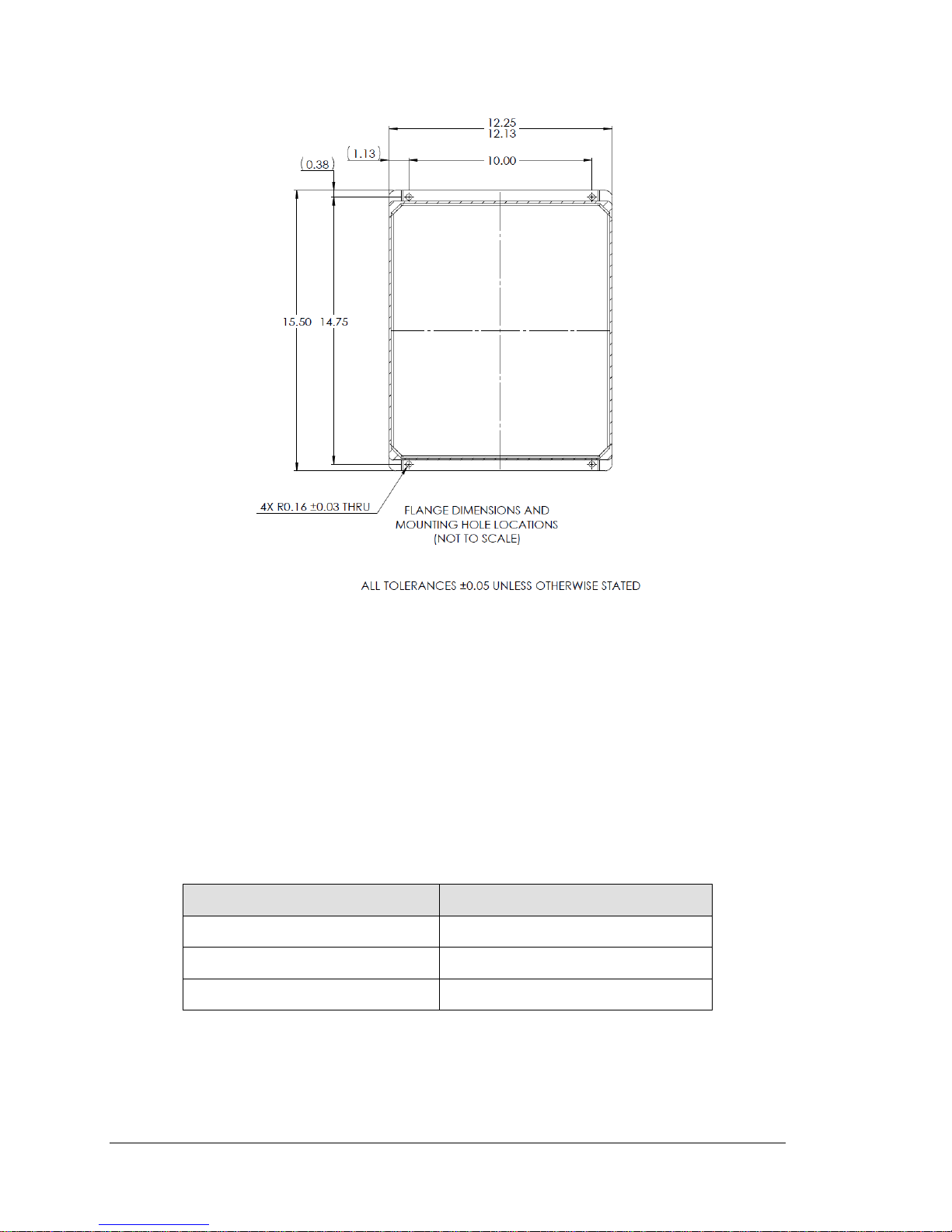
Figure 4-1: 465H Mounting Hole Locations and Dimensions
4.2. Mechanical Installation (19” Rack Version)
The Rack Mount version of the 465H was designed to be operated as a bench-top monitor
or to be mounted in a standard 19” RETMA instrumentation rack. For rack installations,
the four mounting feet should be removed from the bottom of the monitor.
4.2.1. Ventilation Clearance
When installing the 465H be sure to leave sufficient ventilation clearance.
Table 4-2: 465H Ventilation Clearances, Rack Mount Version
Area Minimum required clearance
Back of the monitor 3 inches
Sides of the monitor 1 inch
Above and below the monitor 1/2 inch
14 Teledyne API Model 465H O3 Monitor User Manual 06161H DCN7969
Page 17
4.3. AC Power Connection (for Monitors in
NEMA 4X Enclosure)
WARNING: Electrical Shock Hazard
Disconnect power to the AC mains before making or removing
A proper earth ground connection must be made to the
receptacle labeled “Earth Ground” on the 3 pin AC connector.
Failure to do so may result in a shock hazard and malfunction
4.3.1. Wiring Requirements for NEMA Enclosures
Use appropriate wiring rated for this type of equipment, ensuring that it meets local and
national safety and building requirements.
any electrical connections to the 465H.
WARNING: Electrical Shock Hazard
of the monitor
Ensure that overcurrent protection is used (a 5 A circuit breaker is recommended), and
that it fulfills the following requirements:
belocatedasneartotheinstrumentaspossible
quicklyandeasilyaccessible
clearlylabeledasthedisconnectingdeviceforthisinstrument
4.3.2. Wiring Instructions
1. Install a ½” conduit fitting for routing the electrical wiring into the monitor
through the hole provided in the bottom face of the NEMA enclosure; an
appropriate sealed conduit connector should be used.
2. Attach the leads of the power line to the AC power connector (see Figure 4-6).
06161H DCN7969 Teledyne API Model 465H O3 Monitor User Manual 15
Page 18
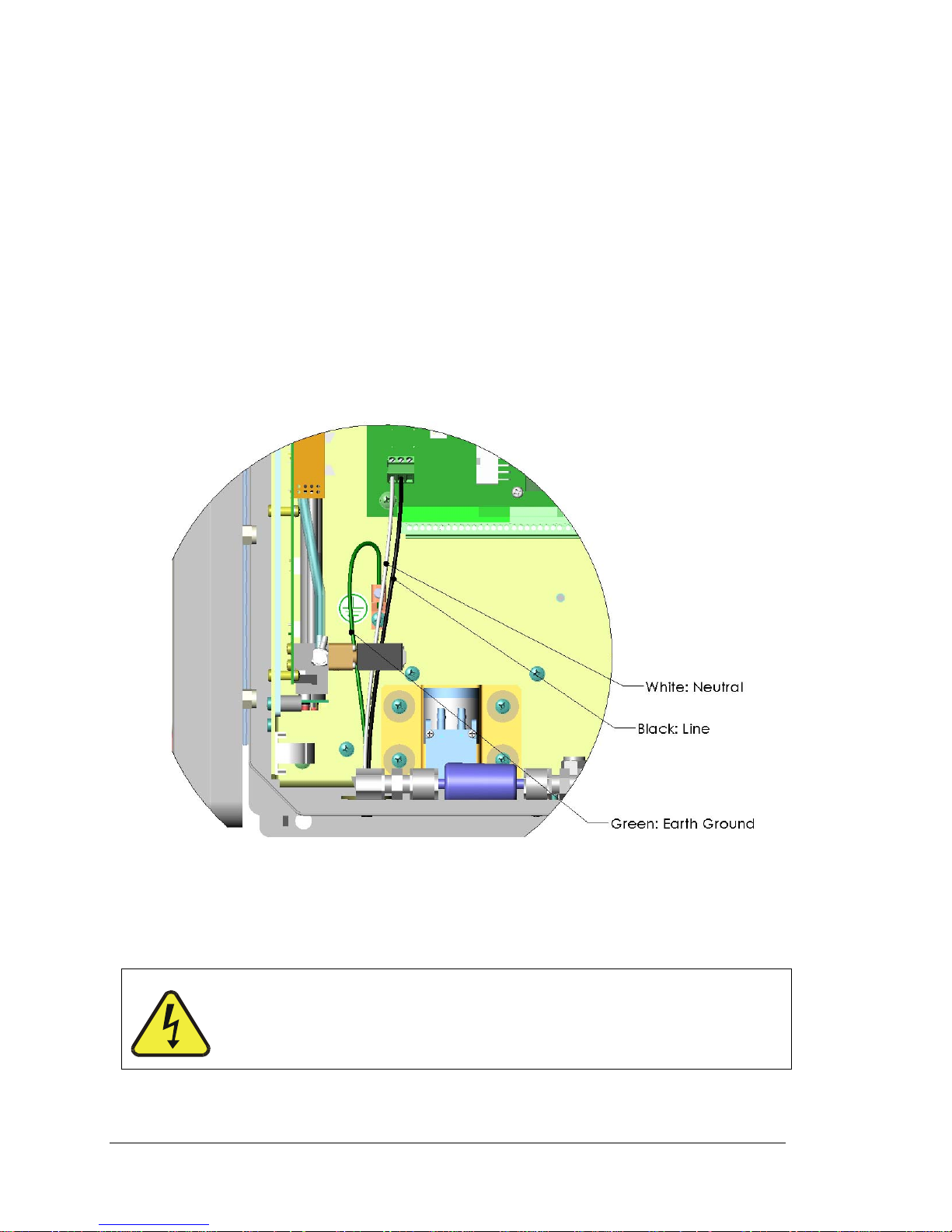
3. For the NEMA configuration, the electrical connection must be hard-wired to the
3-pin connector on the mainboard labeled J23. AC power connection to the
monitor should be made with 12-14 AWG stranded copper wire, connected to the
monitor as follows:
a. Earth Ground (green): Connect the earth ground wire to the screw terminal lug on
the chassis as shown in the Figure below. Do not connect
the earth ground wire directly to the PCB connector on the
mainboard PCB.
b. Line (Black): Connect the Line wire to the connector on the mainboard
PCB labeled “Line”.
c. Neutral (White): Connect the Neutral wire to the connector on the
mainboard PCB labeled “Neutral”.
Figure 4-2. NEMA AC Power Connection to Monitor
4. Connect the power cord to an appropriate power outlet (see the serial number tag
for correct voltage and frequency).
Verify that the instrument is set up for proper line voltage and
frequency. Observe local electrical codes when connecting
power to the monitor.
16 Teledyne API Model 465H O3 Monitor User Manual 06161H DCN7969
WARNING
Page 19
5. Turn on the 465H by switching the switch on the left side of the rear panel, or
applying power to the monitor (NEMA configuration.) The front panel display
should light with a sequence of messages, including the instrument serial number
and software revision. (When the instrument first powers up, the display will
show ‘xxxx’, indicating that the instrument is in start-up mode, waiting for the
UV detector readings to stabilize).
After the start-up period, the instrument will begin displaying the ozone concentration
and the optional stream selector will begin operating, if installed.
4.4. Pneumatic Connections
Figure 4-3: Pneumatic Connections, Rack Mount Configuration
06161H DCN7969 Teledyne API Model 465H O3 Monitor User Manual 17
Page 20
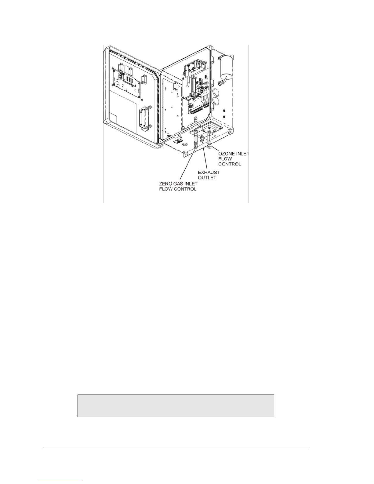
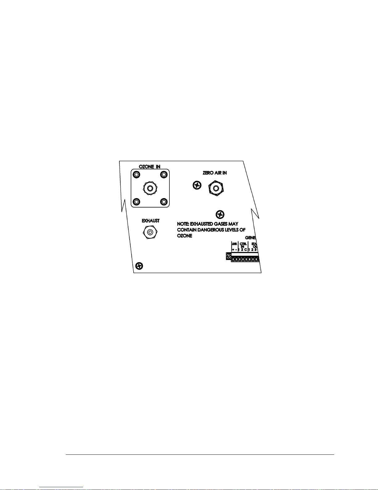
Figure 4-4: Pneumatic Connections, NEMA Configuration
4.4.1. Installing Flow Control Assemblies
Two (2) Flow Control assemblies are supplied separately from the monitor, these are
used to control the flow into the monitor. These Flow Control Assemblies will supply a
fixed flow into the monitor that is dependent on gas supply pressure.
Alternately, customer supplied needle valves can be used in place of these Flow Control
Assemblies if an adjustable flow control is desired. Use only needle valves that are
constructed of materials compatible with high concentrations of ozone, such as stainless
steel and Teflon.
Attach the Flow Control Assemblies by screwing them onto the threaded fittings of the
ozone inlet and the zero gas inlet (see Figure 9-1 and Figure 9-2).
Hand-tighten orifice assemblies until snug.
With a 9/16” open-end wrench, tighten each orifice assembly 1/8–1/4 turn. Use a
1/2” back-up wrench to anchor the fittings of the zero gas and ozone inlet ports in
place.
Do not over tighten the fittings.
NOTE
Both flow control assemblies are identical and interchangeable.
18 Teledyne API Model 465H O3 Monitor User Manual 06161H DCN7969
Page 21

4.4.2. Ozone Inlet Connection
Connect the ozone delivery line to the Flow Control Assembly (See Section 4.4.1) on the
“Ozone Inlet” on the bottom face of the enclosure (See Figure 4-3 and Figure 4-4.) The
ozone delivery should be regulated between 5-30psig.
NOTE
Customers who wish to attach their own flow control devices
(e.g. needle valves) should attach their hardware directly to the
¼” fitting (Swagelok compatible) of the ozone inlet and the zero
gas inlet.
1/4" O.D. FEP (Teflon) or Stainless Steel tubing is recommended to connect the sample
source to the monitor. Any fittings used in the sample lines should also be constructed of
Stainless Steel.
A Flow Control assembly is provided with the monitor, see Section 4.4.1.
4.4.3. Zero Gas Connection
Connect the oxygen or other dry zero gas sources to the to the Flow Control Assembly
(See Section 4.4.1) on the ‘Zero Gas Inlet.’ Zero Gas supply pressure should be regulated
between 5 and 30 psig.
4.4.4. Exhaust Connection
Connect a ¼” OD vent line to the “Exhaust” fitting on the rear panel. This line must be
vented outdoors or to an appropriate discharge system capable of handling ozone. Local
regulations regarding the discharge of ozone to the atmosphere must be observed.
NOTE
The monitor may be equipped with an internal ozone scrubber for
removal of ozone from the exhaust stream. For safety reasons,
the exhaust port must still be vented appropriately as described
above.
CAUTION
Exhaust gas from the 465H may contain dangerous
levels of ozone! Do not vent this gas into enclosed or
occupied areas.
06161H DCN7969 Teledyne API Model 465H O3 Monitor User Manual 19
Page 22

Figure 4-5: Rear Panel Electrical I/O Connections
Figure 4-6: NEMA Electrical I/O Connections
20 Teledyne API Model 465H O3 Monitor User Manual 06161H DCN7969
Page 23

4.5. Electrical I/O Connections
4.5.1. Location of I/O Connectors in the NEMA
Configuration
In the NEMA configuration of the 465H, the I/O connectors are located internally in the
instrument. See Figure 4-6 for their location. Connection to these terminals is usually
made via a conduit connection to the NEMA enclosure. A standard conduit penetration
may be added to one of the walls of the enclosure for this purpose, or the existing
penetration may be used.
The I/O label inside the NEMA cover provides information on the functions of the
connectors. See Figure 4-7 below for the location of the I/O Label.
06161H DCN7969 Teledyne API Model 465H O3 Monitor User Manual 21
Figure 4-7: NEMA I/O Label
Page 24

4.5.2. Analog Output
The analog output is located at the “General I/O” connector (See Figure 4-3.) and is
labeled “ANA.” The analog output can be configured for 0-5V voltage or 4-20 mA
current output. See Section 7.2.5.1 to automatically step-test the analog output.
The analog output is automatically scaled to the range of the instrument, i.e. if the
monitor range is 100 g/Nm3, then 5V would correspond to 100 g/Nm3 and 0V would
correspond to 0 g/Nm3. See Section 7.2.4 for information on changing the range of the
monitor.
4.5.3. Status Outputs
There are four instrument status outputs located at the “General I/O” connector. These
status outputs mirror the state of the four diagnostic LED’s on the front panel. If any of
these status outputs are in a different state than shown in Table 4-3 then some adjustment
or troubleshooting should be performed. See Section 10.2 for more detailed information.
Electrically these outputs are SPST dry contact relay closures with a common contact,
labeled ‘C’ on the rear panel. They are capable of switching up to 50 VDC, 250mA
maximum current. There are no polarity requirements, so the outputs can be used to sink
or source current from the ‘C’ pin, within the maximum voltage and current specified.
Schematically, the outputs look as shown in Figure 4-8 below:
Figure 4-8: Status Output Schematic
22 Teledyne API Model 465H O3 Monitor User Manual 06161H DCN7969
Page 25

The outputs are defined as follows:
Table 4-3: Status Output Definitions
Status
Output #
Name Normal Operating
State
1 Sensor OK On
2 Invalid Reading Off
3 Check Lamp Off
4 Pneumatic Error Off
4.5.4. Hi-Current Relay Outputs
Three form C relay outputs are provided on the rear panel on the nine pin connector (see
Figure 4-5). The relays are labeled “Relay 1,” “Relay 2,” and “Relay 3.”
The relays are dry contact type form C (SPDT) relays with Normally Open (N.O.),
Normally Closed (N.C.) and Common (COM) contacts. The relays are capable of driving
loads of up to 250VAC, 5A. For maximum contact life, the relays should only be used to
drive resistive loads. Contact life may be dramatically shortened if inductive loads are
driven without any provision for minimizing a high voltage “inductive kick” that can
occur. See Section 7.2.3 to configure the alarms.
Table 4-4: Relay Functions
Relay # Function Normal
Operating State
1 System OK Diagnostic
On
(Identical to Sensor OK
status output as
described in Table 4-3)
2 Hi Alarm Off
3 Hi-Hi Alarm Off
06161H DCN7969 Teledyne API Model 465H O3 Monitor User Manual 23
Page 26

4.5.5. Digital Serial Interfaces
There is one external communications port that can be configured for either the RS232,
RS485 (Half Duplex,) or Ethernet (10Mbit.) This section provides only a brief overview
of the digital serial connections. For more detailed information on configuring and using
the digital serial interfaces, see Section 8.
4.5.5.1. RS232 Connection
With the instrument configured for RS232, connection can be made to the DB-9
connector, labeled “RS232/485”, or to the three “COM” pins on the “General I/O”
connector. See Section 8.2 for additional details.
When using RS232, a 9-pin serial cable (TAPI P/N WR77) can be used to connect the
instrument to a standard PC (personal computer) serial port.
4.5.5.2. RS485 Connection
With the instrument configured for RS485, connection can be made to the DB-9
connector, labeled “RS232/485”, or to the three “COM” pins on the “General I/O”
connector. See Section 8.2 for additional details.
4.5.5.3. Ethernet Connection
With the instrument configured for Ethernet, connection should be made to the RJ-45
port labeled “Ethernet.” Connection can be made using a standard Category 5 or better
network patch cable. See Section 8.2 for additional details. TAPI can provide an
appropriate cable.
24 Teledyne API Model 465H O3 Monitor User Manual 06161H DCN7969
Page 27

5. FREQUENTLY ASKED QUESTIONS
6. Q: How long does the UV Lamp last?
A: The typical lifetime is about 2-3 years.
The lamp output will steadily decrease until lamp adjustment can no longer be
performed. The "Check Lamp" warning LED will tell the operator when this
adjustment should be attempted. When this adjustment can no longer be
performed, the lamp should be replaced. See Chapter 1 for more information.
06161H DCN7969 Teledyne API Model 465H O3 Monitor User Manual 25
Page 28

6. HARDWARE AND SOFTWARE OPTIONS
6.1. Rack Mount Slides
Rack mount slides can be attached to the sides of the instrument, allowing it to slide
completely out of a RETMA rack, facilitating maintenance activities.
6.2. Ethernet (MODBUS
The Ethernet option consists of a converter that provides a MODBUS® TCP/IP interface
to the monitor.
®
TCP/IP)
26 Teledyne API Model 465H O3 Monitor User Manual 06161H DCN7969
Page 29

7. OPERATION
7.1. Front Panel Overview
The 465H front panel provides a number of functions in addition to displaying the current
ozone concentration being measured. Figure 7-1 below shows the display and keypad
portion of the front panel.
Figure 7-1: Front Panel Display
7.1.1. Ozone Concentration Display
The 4-character LED display in the center of the front panel normally shows the current
ozone concentration being measured by the 465H. While displaying concentration, one
of the unit-of-measure indicators (i.e. WT%, or g/Nm3) should be backlit, indicating the
current measurement units. If none of these indicators are backlit, then the display is in
Menu mode or Startup mode and is not displaying the concentration. If the display is in
Menu mode, the display can be returned to Concentration mode by repeatedly pressing
the CFG button until one of the unit-of-measure indicators is lit.
NOTE
Even when the display is in Menu mode, normal measurement
and stream selector operation will continue in the background.
7.1.2. Menu Navigation Keypad
The menu navigation keypad (CFG, ENT and UP/DOWN buttons) is used to navigate
the various menu items available on the 465H. The menus allow the operator to view
operational parameters of the instrument as well as view and modify the configuration of
the instrument. See Section 7.2 for more detailed information.
06161H DCN7969 Teledyne API Model 465H O3 Monitor User Manual 27
Page 30

7.1.3. Concentration Alarm Status/Reset
The 465H front panel displays the concentration alarm status of the sample gas. The
LED labeled ‘ALARM STATUS’ shows the alarm status as follows:
Table 7-1: Alarm LED’s
Alarm Status LED Color Alarm State
Green No alarm active
Amber ‘HI’ alarm active
Red ‘HI-HI’ alarm active
If the alarms are configured for latching operation, then the RESET button can be used to
attempt to reset all alarms.
NOTE
Alarms can only be reset if the concentration measured has
subsequently dropped below the alarm limit.
If the alarms are configured for non-latching operation, they will be automatically cleared
when the concentration falls below the alarm threshold. The RESET button has no effect
when the alarms are configured for non-latching operation.
See Sections 7.2.3 and 4.5.4 for additional details on concentration alarms.
7.1.4. Status LED’s
There are four Status LED’s on the front panel to the right of the concentration display.
These LED’s provide a quick view of the instrument’s Status and provide indication of
any problems that may exist. The normal state for these LED’s after the initial warm-up
period is as follows:
Table 7-2: Status LED’s
Status LED Normal State
Sensor OK ON
Invalid Reading OFF
Check Lamp OFF
Pneumatic Error OFF
If any of these LED’s are in a different state than shown above, then some adjustment or
troubleshooting should be performed. See Section 10.2 for more detailed information.
28 Teledyne API Model 465H O3 Monitor User Manual 06161H DCN7969
Page 31

7.2. Front Panel Menus
The 465H has an interactive menu structure that can be operated from the front panel.
From within this menu structure, the operator can view real-time parameters such as
temperature and pressure, view configuration information, and edit setup parameters such
as alarm limits.
Figure 7-2 and Figure 7-3 below show the menu structure as well as the buttons that are
used to navigate it.
Starting with the display in Concentration mode, press CFG to enter Menu mode. At this
point the unit-of-measure LED should turn off and the first level of the Menu tree will be
active. Pressing the UP/DOWN arrows will now select from the items available at this
menu level. Press ENT to enter one of these sub-menus or press CFG to back out of this
menu level back to Concentration mode.
7.2.1. Menu Navigation Basics
1. Press CFG from Concentration mode to enter Menu mode.
2. Once in Menu mode, CFG will move backwards one level in the menu structure
and ENT will move forward.
3. Each menu level contains an EXIT selection. Selecting EXIT and pressing ENT
will exit the Menu mode and return the display to Concentration mode.
7.2.2. Editing Numeric Values
At certain places in the menu structure the operator can edit numeric values. The menu
buttons behave somewhat different when in this mode.
Press CFG to select a digit to edit. The selected digit will blink. Next press the
UP/DOWN arrows to increment/decrement the selected digit. Press CFG again to select
another digit. Pressing CFG at the last digit will wrap back to the first digit.
Once all the digits have been edited, press ENT to accept the new value.
To abort the editing process without changing the original value, press and hold the CFG
button until the display returns to the previous menu level.
NOTE
Limit checking is enforced, while editing values and changes that
would result in invalid values are ignored.
06161H DCN7969 Teledyne API Model 465H O3 Monitor User Manual 29
Page 32

Figure 7-2: Front Panel Menu Diagram
30 Teledyne API Model 465H O3 Monitor User Manual 06161H DCN7969
Page 33

DIAG
VIEW
ENT
ENT
SEE PREVIOUS
PAGE
SEE PREVIOUS
PAGE
ANALOG
STEP TEST
SIGNAL I/O
MEMORY
RESET
ZERO CAL
SPAN CAL
STORE
VARS
RESTORE
VARS
EXIT
MEAS
REF
ENT
ENT
ENT
ENT
ENT
ENT
ENT
See Section
6.2.5.1
See Section
6.2.5.2
See Section
6.2.5.3
See Section
6.2.5.4
See Section
6.2.5.5
Unavailable
Unavailable
CFG
M465H-Front Panel Menu Diagram, Rack Mount
ENT
SEE PREVIOUS
Figure 7-3: Front Panel Menu Diagram
PAGE
PRESSURE
LAMP
TEMP
SAMPLE
TEMP
FLOW
EXIT
S/N
COMM
ADDRESS
REV
BOOT
EXIT
See Section
6.2.6
See Section
6.2.7
06161H DCN7969 Teledyne API Model 465H O3 Monitor User Manual 31
Page 34

7.2.3. SETUP-ALARM Menu
The ALARM menu gives the option of enabling/disabling the HI, and HI-HI alarms, as
well as setting the concentrations at which they are triggered. The options available:
Table 7-3: Alarm Configuration Properties
Property Meaning Default Value Range
HI ALARM HI alarm trigger value 1.00 WT%,
1.00 g/Nm3
HIHI ALARM HI-HI alarm trigger value 1.02 WT%,
1.02 g/Nm3
ON/OFF HI
ALARM
ON/OFF HI HI
ALARM
HI alarm enable, enables HI alarm
operation
HI-HI alarm enable, enables HI-HI
alarm operation
ON ON/OFF
ON ON/OFF
0.02%-25.0%
0.02-400 g/Nm3
0.02%-25.0%
0.02-400 g/Nm3
32 Teledyne API Model 465H O3 Monitor User Manual 06161H DCN7969
Page 35

7.2.4. SETUP-VARS Menu
The VARS menu allows viewing and editing of various global setup variables that effect
how the 465H operates. These variables are stored in the instrument’s non-volatile
memory. Table 7-4 lists these variables and their function.
Table 7-4: VARS List
VAR Meaning Default
ALARM MODE Controls the latching behavior of
the concentration alarms. See
Section 7.1.3 for additional details.
ALARM DELAY Number of readings above alarm
limit required to trigger alarms
BC FILT SIZE Boxcar filter’s length for
concentration filter. Higher values
will smooth out the concentration
readings but will also increase the
response time.
FLOW SWITCH
ENABLE
COMM ADDRESS MODBUS® address for COM
UNIT Concentration unit-of-measure
Enables/disables operation of
optional flow switch
ports.
setting.
Range
Value
LATCHING LATCHING,
NONLATCHING
5 1 - 20
30 1-30
OFF ON, OFF
1 1 - 247
g/Nm3 WT%, g/Nm3
SCROLL DELAY Character delay for the front panel
display.
AZERO ENABLE Enables/Disengages zero
calibration
AZERO
INTERVAL
GAS CARRIER
WEIGHT
ANALOG RANGE Voltage range corresponding to
Interval at which zero calibration is
performed. (minutes)
Weight of gas without ozone, used
in %Weight measurement
ozone concentration.
20 6-100
ON ON/OFF
720 3-1440
32.00 20.0-40.0
20 5 – 50 g/Nm3
0.5 – 25.0 wt%
06161H DCN7969 Teledyne API Model 465H O3 Monitor User Manual 33
Page 36

7.2.5. DIAG Menu
The DIAG menu (See Figure 7-2 and Figure 7-3) contains functions that are useful for
calibration and I/O testing.
7.2.5.1. Analog Step-Test
When placed in this mode, the instrument will automatically step the analog output
through 5 points from 0 to 100 % and display the current value on the front panel. The
operator can suspend the automatic cycling and manually control the stepping by pressing
either one of the UP / DOWN arrow buttons. To resume automatic cycling, exit the
function by pressing CFG and re-enter by pressing ENT.
The 5 points will correspond to the following analog output values depending on whether
the output is configured for 0-5V or 4-20mA:
Table 7-5: Analog Step Test Values
Point 0-5V Output 4-20 mA Output
0% 0.00 V ± 0.02 4 mA ± 0.02
25% 1.25 V ± 0.02 8 mA ± 0.02
50% 2.50 V ± 0.02 12 mA ± 0.02
75% 3.75 V ± 0.02 16 mA ± 0.02
100% 5.00 V ± 0.02 20 mA ± 0.02
Press CFG to exit from the Analog Step-Test function.
7.2.5.2. Signal I/O
The Signal I/O menu allows the operator to manually control the various relay outputs
and control inputs available on the rear panel of the 465H. This function is useful for
testing or debugging external control systems (i.e. data-loggers or PLC’s) to which the
instrument may be connected.
See Section 4.5 for additional details on making connections to these I/O signals on the
rear panel.
See Figure 7-2 and Figure 7-3 for additional details on entering the Signal I/O menu.
34 Teledyne API Model 465H O3 Monitor User Manual 06161H DCN7969
Page 37

Table 7-6: Signal I/O List
Signal Name Rear Panel Label Function
AUX 1 IN CTRL IN - 1 UNDEFINED
AUX 2 IN CTRL IN - 2 UNDEFINED
RELAY 1 RELAY 1 SENSOR OK
RELAY 2 RELAY 2 HI ALARM
RELAY 3 RELAY 3 HI-HI ALARM
STAT OUT 1 STATUS OUT – 1 SENSOR OK
STAT OUT 2 STATUS OUT – 2 INVALID READING
STAT OUT 3 STATUS OUT – 3 CHECK LAMP
STAT OUT 4 STATUS OUT – 4 PNEUMATIC ERROR
STAT AUX 1 AUX OUT – 1 UNDEFINED
STAT AUX 2 AUX OUT – 2 UNDEFINED
7.2.5.3. Memory Reset
This function is currently disabled.
7.2.5.4. Zero Calibration
This function performs a zero calibration based on gas from the “Zero In” port.
If the Auto Zero calibration is enabled, the internal ozone offset factor will automatically
be adjusted every 720 minutes. If the zero calibration is disabled, then manual calibration
is necessary based on the customer’s applications. For normal applications, the Auto Zero
is not necessary.
The zero calibration allows the instrument to calibrate its internal ozone offset factor.
This should only be done with a source of zero air connected to the “Zero In” port of the
465H. Allow the instrument to stabilize on the zero air source before attempting to zero
the instrument. This normally takes 10-15 minutes.
When entering the Zero Calibration menu, the prompt “ENT TO CAL” appears on the
display. Simply confirm the calibration by pressing the ENT button to perform the
calibration (to abort the calibration, press and hold the CFG button to return to the
previous menu level.) After pressing ENT, the instrument will automatically exit the
menu mode and return to Concentration mode. The concentration reading should quickly
go to zero.
06161H DCN7969 Teledyne API Model 465H O3 Monitor User Manual 35
Page 38

NOTE
While measuring zero air, a certain amount of noise or
“dithering” of the concentration about the zero point will occur
and is normal. This noise is typically 0.01-0.02 Wt% in
magnitude.
7.2.5.5. Span Calibration
The Span Calibration also allows the instrument to calibrate its internal ozone offset
factor. The Span Calibration however, is done with some controlled concentration gas
connected to the “Sample In” port of the 465H. It is recommended that a span gas is
concentrated to around 80% of the operating range. Set the SPAN VALUE to the
measured concentration of your calibration gas. This normally takes 10-15 minutes.
NOTE
A Span Calibration should only be performed with a stable
source of Ozone and a reference monitor measuring the same gas
supply.
If you are unsure regarding the suitability of a particular source
of calibration gas, contact Technical Support at Teledyne API for
assistance (see Section 0.)
See Figure 7-4 shows the Span Cal menu. After the instrument has stabilized on the
source of span gas, navigate to the Span Cal menu (See Figure 7-2 and Figure 7-3) and
Press ENT. Next enter the Span Target concentration (the actual concentration of ozone
being supplied to the monitor) and press ENT. The display will next show a
confirmation menu, ENT TO SPAN. Press ENT to perform the Span Calibration, or
CFG to abort back to the start. If the calibration is successful, the display will return to
the concentration menu and the monitor reading should change adjust to read very close
to the target value. If the calibration cannot be performed, an OUT OF RANGE error
will be displayed. Press ENT to confirm and the display will return to the start of the
Span Cal menu.
If the OUT OF RANGE error occurs, it means the Span Cal cannot be performed
because it would result in an out of range slope value for the monitor. This means that
either the sensor in the monitor is malfunctioning, causing improper readings, or the
actual ozone concentration being supplied to the monitor is different than the target value
being entered.
36 Teledyne API Model 465H O3 Monitor User Manual 06161H DCN7969
Page 39

Figure 7-4: Span Cal Menu
7.2.6. VIEW Menu
The VIEW menu allows the operator to view various measurement parameters in realtime. This can be useful for diagnosing various instrument or system problems.
NOTE
These values are updated in real-time as they are repeatedly
scrolled on the display.
Table 7-7: VIEW Menu Parameters
Parameter Meaning Units Normal Range*
MEAS UV detector reading, measure cycle mV 250 – 1230
REF UV detector reading, reference
cycle
PRESSURE Sample pressure psia 9.0 – 18.0
LAMP
UV lamp temperature ºC 50.0 – 52.0
TEMP
SAMPLE
Sample temperature ºC 5.0 –50.0
TEMP
mV 250 – 1230
FLOW Flow Switch State ** ON/OFF ON
*After initial 20 minute warm-up period.
** Only available if Flow Switch Option is installed.
06161H DCN7969 Teledyne API Model 465H O3 Monitor User Manual 37
Page 40

7.2.7. CONFIG Menu
The CONFIG menu displays important information about the instrument. The Serial
Number, COMM address settings, and the latest revision of software installed are
information available in the CONFIG menu. Settings can be changed under other menus
(see sections 7.2.3, 7.2.4, and 7.2.5); however the CONFIG menu just contains
instrument-specific information.
7.3. Analog Output
The 465H provides an analog output of the current O3 reading on the rear panel (see
Section 4.5.2). The output can be configured for 0-5V or 4-20mA isolated current output.
The analog output provides a scaled, real-time output of the current ozone concentration
being measured by the instrument. See Section 7.2.4 for details on changing the analog
output range. See Section 9.6 for details on configuring the output for 0-5 V or 4-20 mA.
38 Teledyne API Model 465H O3 Monitor User Manual 06161H DCN7969
Page 41

8. DIGITAL COMMUNICATIONS
8.1. Digital Communications Overview
The 465H comes equipped with a digital communications (COM) port that can be
connected to a computer or digital data acquisition system. This COM port uses the
standardized MODBUS® protocol and can be configured for RS232, RS485, or Ethernet
(10 Mbit,) allowing for connections to a wide variety of devices and networks. See
Section 8.2 for more information on configuring the COM port.
The COM port can be used for data acquisition, alarm triggering, and instrument
configuration. All the functions that are available at the front panel of the instrument can
also be performed over the COM port.
NOTE
The APICOM software provided by Teledyne API does not currently
support communications with the 465H. Contact TAPI for more
information on compatible MODBUS® software that can be used
with the 465H.
8.2. Changing COM Port Hardware
Configuration
The operations outlined in this section are to be performed by
The COM port can be configured for RS232, RS485, or Ethernet. To change the COM
port hardware configuration, perform the following steps:
1. Disconnect power from the 465H.
2. Remove the six screws and the top cover.
3. Locate the DIP switches labeled SW3 on the rear portion of the mainboard.
4. Turn ON the switches specified for the desired COM configuration (See Figure
8-1.) All other switches on SW3 should be OFF.
WARNING: Electrical Shock Hazard
qualified maintenance personnel only!
5. Locate SW2 (DTE-DCE switch) on mainboard.
06161H DCN7969 Teledyne API Model 465H O3 Monitor User Manual 39
Page 42

6. For RS-232 operation, set SW2 to either DTE or DCE (See Section 8.3.) For RS-
485 operation, set SW2 to DCE.
7. Re-install the instrument cover.
8. Re-connect power to the instrument.
9. The software portion of the COM port configuration will now automatically be
completed after the next instrument boot-up.
SW3
3
4
21
765
1098
RS232 Configuration
ETHERNET
SW3
RS485
Close Indicated Positions Only
3
4
21
765
RS232
1098
RS485 Configuration
ETHERNET
SW3
RS485
Close Indicated Positions Only
1234
567
RS232
8910
Ethernet Configuration
ETHERNET
RS485
Close Indicated Positions Only
Figure 8-1: COM Configuration Jumper Settings (SW3)
RS232
40 Teledyne API Model 465H O3 Monitor User Manual 06161H DCN7969
Page 43

8.3. RS-232 Configuration
The RS-232 configuration is usually used when making a one-to-one connection between
the instrument and a single computer or PLC. The communications protocol used for the
RS-232 configuration is MODBUS
specification, please see http://www.modbus.org/.
With the instrument configured for RS-232, connection can be made to the DB-9
connector, labeled “RS232/485”, or to the three “COM” pins on the “General I/O”
connector. Only one of these connections should be used, the other must be left unconnected. Table 8-1 below details the pinouts of these two connectors:
Table 8-1: RS-232 Connector Details
®
RTU. For details on the MODBUS® RTU
Function DB-9
Connector Pin
(SW2 – DTE)
DB-9
Connector Pin
(SW2 – DCE)
General I/O
Connector
Transmit (Tx) 3 2 ‘T’
Receive (Rx) 2 3 ‘R’
Ground 5 5 ‘G’
NOTE
A DTE-DCE switch is provided so that the instrument can be
connected to another device using either a straight-through or
crossover (Null-Modem) cable. See Section 8.2 for details on
changing this configuration.
The serial port setup for RS-232 configuration is shown in Table 8-2 below:
Table 8-2: RS-232 Port Setup
Property Value
06161H DCN7969 Teledyne API Model 465H O3 Monitor User Manual 41
Baud Rate 57600
Data Bits 8
Parity None
Stop Bits 1
Flow Control None
Page 44

8.4. RS-485 Configuration
RS-485 is commonly used for factory automation busses with a computer or PLC acting
as a master. The communications protocol used for the RS-485 configuration is
MODBUS
http://www.modbus.org/.
With the instrument configured for RS-485, connection can be made to the DB-9
connector, labeled “RS232/485”, or to the three “COM” pins on the “General I/O”
connector. Table 8-3 below details the pinouts of these two connectors:
®
RTU. For details on the MODBUS® RTU specification, please see
Table 8-3: RS-485 Connector Details
Function DB-9
Connector Pin
General I/O
Connector
(SW2 – DCE)
RS485 - A 2 ‘T’
RS485 - B 3 ‘R’
Ground 5 ‘G’
NOTE
For RS-485 configuration, the DTE-DCE switch should always
be set to DCE. See Section 8.2 for details on changing this
configuration.
The serial port setup for RS-485 configuration is shown in Table 8-4 below:
Table 8-4: RS-485 Port Setup
Property Value
Baud Rate 57600
42 Teledyne API Model 465H O3 Monitor User Manual 06161H DCN7969
Data Bits 8
Parity None
Stop Bits 1
Flow Control None
Page 45

8.5. Ethernet Configuration
Ethernet is commonly used for factory automation busses with a computer or PLC acting
as a master. The communications protocol used for the Ethernet configuration is
MODBUS
http://www.modbus.org/.
A Windows software application, DeviceInstaller, is available for configuring the
Ethernet module used in the 465H. This application is available for download here:
http://www.lantronix.com/device-networking/utilities-tools/device-installer.html
8.5.1. Hardware Setup for Configuring the Ethernet
To make the first-time configuration of the Ethernet module as easy as possible, the
module comes from the factory with DHCP enabled. The 465H can simply be plugged
into a network with a DHCP server and an IP Address should be automatically assigned
to, and stored in, the device.
A simple network can easily be constructed for this purpose by using a small broadband
router commonly used for home networks. The 465H and a PC can then be connected to
the router and the router’s DHCP server will assign IP Addresses to both the PC and the
465H, enabling them to communicate.
®
TCP/IP. For details on the MODBUS® TCP/IP specification, please see
Module
8.5.2. Verifying Network Hardware Connection
With the 465H connected to a network and powered up, check the status of the two
LED’s on the Ethernet connector on the rear panel. The left-hand LED should be lit;
either amber or green indicating link status and the right-hand led should blink
periodically, indicating activity on the network. See Table 8-5 below for more details on
the status LED’s.
If neither of the LED’s are lit, then the Ethernet module may not be powered up or the
instrument may not be connected to a valid network. Check the COM port configuration
per Section 8.2 and make sure that it is set to “Ethernet.”
Table 8-5: Ethernet LED Definitions
Link LED (Left Side) Activity LED (Right Side)
Color Meaning Color Meaning
Off No Link Off No Activity
Amber 10 Mbps Connection Amber Half-Duplex
Green 100 Mbps Connection Green Full-Duplex
06161H DCN7969 Teledyne API Model 465H O3 Monitor User Manual 43
Page 46

8.5.3. Determining a Dynamically Assigned IP Address
(DHCP Mode)
The DeviceInstaller software application (See Section 8.5) can be used to search a
network for instruments and determine the IP Address assigned by a DHCP server.
1. Click Start->Programs->Lantronix DeviceInstaller->DeviceInstaller. If
your PC has more than one network adapter, a message displays. Select an
adapter and click OK.
2. Click on the Search icon. After a moment a list of instruments on the network
will be displayed. The 465H should be listed as an XPORT-IAP type device.
3. Double-click on the device in the right-hand section of the DeviceInstaller
window; a list of configuration parameters will be shown, including the IP
Address. If multiple devices are shown, the correct one can be determined by
matching the Hardware Address shown with the address printed on the label of
the Ethernet module in the 465H.
NOTE
The instrument cover must be removed to inspect this address in
the instrument.
8.5.4. Manually Assigning a Static IP Address
For applications where the IP Address must remain constant, a static IP Address can be
manually assigned to the instrument and the DHCP function must be disabled.
1. Click Start->Programs->Lantronix DeviceInstaller->DeviceInstaller. If
your PC has more than one network adapter, a message displays. Select an
adapter and click OK.
NOTE
If the unit already has an IP address (e.g., DHCP has assigned an
IP address), click the Search icon and select the unit from the list
of Lantronix device servers on the local network.
2. Click the Assign IP icon.
3. If prompted, enter the hardware address (on the product label) and click Next.
4. Select Assign a specific IP address and click Next.
44 Teledyne API Model 465H O3 Monitor User Manual 06161H DCN7969
Page 47

5. Enter the IP address. The Subnet mask displays automatically based on the
IP address; if desired, you may change it. On a local network, you can leave the
Default gateway blank (all zeros). Click Next.
6. Click the Assign button and wait several seconds until a confirmation message
displays. Click Finish.
7. Select the device from the main window list and select Ping from the Tools
menu. The Ping Device dialog box shows the IP address of the selected unit.
8. From the Tools menu, click the Ping button. The results display in the Status
window. Click the Clear Status button to clear the window so you can ping the
device again.
NOTE
If you do not receive “Reply” messages, make sure the unit is
properly attached to the network and that the IP address assigned
is valid for the particular network segment you are working with.
If you are not sure, check with your systems administrator.
9. Click the Close button to close the dialog box and return to the main window.
8.6. MODBUS
8.6.1. Notes on MODBUS
Concentration values in the MODBUS® registers are always expressed in terms of the
desired 465H settings, whether in %WT or g/Nm3.
®
Register Maps
®
registers
06161H DCN7969 Teledyne API Model 465H O3 Monitor User Manual 45
Page 48

8.6.2. Real-Time Concentration and Status Registers
(Read Only)
Decimal
Address Description Register Type
1 Stream Concentration Float Inverse 0 32
3 Hi Alarm Status Byte 0 8
3 Hi Hi Alarm Status Byte 8 8
4 Gas Flow (cc/min) Float Inverse 0 32
19 Sensor Reference Value Float Inverse 0 32
21 Sensor Measure Value (mV) Float Inverse 0 32
23 Sensor Pressure Value (mV) Float Inverse 0 32
25 Sensor Gas Temperature (K) Float Inverse 0 32
27 Sensor UV Lamp Temperature (oC) Float Inverse 0 32
Start
Bit # Bits
8.6.3. Instrument Setup and Configuration Registers
(Read / Write)
Decimal
Address Description
1030 Hi Alarm Value (WT%) Float Inverse 0 32
1032 Hi Hi Alarm Value (WT%) Float Inverse 0 32
1034 Hi Alarm Enable (WT%) Byte 0 8
1034 Hi Hi Alarm Enable (WT%) Byte 8 8
1035 Alarm Latch Mode Byte 0 8
1038 Analog Range (WT%) Float Inverse 0 32
Register
Type
Start
Bit # Bits
46 Teledyne API Model 465H O3 Monitor User Manual 06161H DCN7969
Page 49

9. MAINTENANCE
The operations outlined in this section are to be performed by
WARNING: Electrical Shock Hazard
qualified maintenance personnel only!
9.1. Maintenance Schedule
Table 9-1 outlines the suggested maintenance procedures and intervals for ensuring the
465H continues to operate accurately and reliably.
Table 9-1: Maintenance Schedule
Maintenance Item Recommended Interval Section
Replace particulate filter 6 months 9.3
Adjust UV lamp As Indicated by ‘Check Lamp’
LED or status output
Replace lamp As required; when adjustment can
no longer be performed.
Replace Auto Zero Valve Annually 9.6
Rebuild cell, replace orings
3 Years Return
9.4
9.5
to
Factory
06161H DCN7969 Teledyne API Model 465H O3 Monitor User Manual 47
Page 50

9.2. Instrument Layout
Figure 9-2 show the instrument layout of the 465H. These figures will be referenced in
the procedures that follow.
Figure 9-1: Instrument Layout, Rack Mount Configuration
48 Teledyne API Model 465H O3 Monitor User Manual 06161H DCN7969
Page 51

Figure 9-2: Instrument Layout, NEMA Configuration
06161H DCN7969 Teledyne API Model 465H O3 Monitor User Manual 49
Page 52

9.3. Replacing Internal Particulate Filter
1. Disconnect power from the 465H.
2. Loosen the six screws from the top cover (Rack Mount Configuration, see Figure
9-1) or open front panel (NEMA Configuration, see Figure 9-2.)
3. Remove the six screws and top cover from the instrument.
4. Locate the particulate housing filter on the rear panel (Rack Mount Configuration,
see Figure 9-1) or the bottom panel (NEMA Configuration, see Figure 9-2.)
5. Loosen the four screws on the sample filter body (see Figure 9-3.)
6. Remove the fours screws, the four washers and the sample filter body from the
sample filter base.
7. Remove the o-ring and inspect for any cracks or deformities. If there are no
cracks or deformities, place the o-ring back in the sample filter body.
NOTE
If the o-ring is cracked or deformed, discard the o-ring and
replace with a new one.
8. Remove the two sample filter retainers and glass fiber filter element from the
sample filter body.
9. Discard the glass fiber filter element.
10. Place a new glass fiber filter element in between the two sample filter retainers
and place in the sample filter body.
11. Place the sample filter body on the sample body base and secure with the four
screws and fours washers.
12. Reinstall the top cover on the instrument and secure with the six screws or close
the front panel.
50 Teledyne API Model 465H O3 Monitor User Manual 06161H DCN7969
Page 53

Figure 9-3: Internal Particulate Filter Replacement
9.4. UV Lamp Adjustment
1. Instrument should be running and warmed up for at least 20 minutes.
2. With instrument running, remove the six screws and the top cover (Rack Mount
Configuration) or open front panel (NEMA Configuration.)
3. Locate the Reference UV Detector adjustment pot, PR3, on the Mainboard PCA
(see Figure 9-1 or Figure 9-2.)
4. Navigate the front panel menu to VIEW menu and scroll to REF display and press
ENT. At this point there should be a scrolling display similar to “REF = XXXX
MV.” See Section 7.2 for details on menu navigation.
5. While observing the REF value on the display, slowly turn the pot to adjust the
value. The target adjustment range is as high as possible within the range of 800
– 1150 mV.
6. Locate the Measure UV Detector adjustment pot, PR4, on the mainboard PCA
(see Figure 9-1 or Figure 9-2.)
7. Navigate the front panel menu to VIEW menu and scroll to MEAS display and
press ENT. At this point there should be a scrolling display similar to “MEAS =
XXXX MV.” See Section 7.2 for details on menu navigation.
8. While observing the MEAS value on the display, slowly turn the pot to adjust the
value. The target adjustment range is as high as possible within the range of 800
– 1150 mV.
06161H DCN7969 Teledyne API Model 465H O3 Monitor User Manual 51
Page 54

9. If the required adjustment cannot be achieved by adjusting the UV Detector pot
alone, then additional adjustment can be made by loosening the two UV lamp
setscrews on the UV lamp housing (see Figure 9-1 or Figure 9-2) and rotating the
lamp. Rotate the lamp very slowly while observing the REF or MEAS value on
the display. Make sure the lamp does not pull out and remains seated in the
housing while it is being rotated. Re-tighten the two setscrews when a desired
point has been reached.
10. If necessary, additional “fine tuning” can now be done with the UV Detector
adjustment pots per steps 4-8.
11. Re-Install instrument cover and observe REF and MEAS values on display for a
couple minutes to verify it does not drift out of the adjustment range.
9.5. UV Lamp Replacement
1. Disconnect power from the 465H.
2. Remove the six screws and the top cover (Rack Mount Configuration) or open
front panel (NEMA Configuration.)
3. Loosen the two UV lamp setscrews on the UV lamp housing (see Figure 9-1 or
Figure 9-2.)
4. Unplug the lamp power cord from the connector labeled J18 on the mainboard
PCA.
5. Carefully slide the lamp out of housing.
6. Install the new lamp, seating it in the lamp housing until it stops.
7. Re-tighten the two UV lamp setscrews.
8. Plug the lamp power cord into J18 on the mainboard PCA.
9. Reconnect power to the instrument and turn on power switch. Let instrument
warm up for at least 20 minutes.
10. Perform UV lamp adjustment procedure per Section 9.4.
9.6. Replacing the Auto-Zero Valve
1. Disconnect power from the 465H.
2. Remove the six screws and the top cover (Rack Mount Configuration) or open
front panel (NEMA Configuration.)
3. Locate the auto-zero valve (See Figure 9-1 or Figure 9-2.)
4. Unplug the two-pin valve connector from the mainboard PCA.
5. Remove the 1/8” fittings from the valve.
6. Remove the bulkhead nut (from outside the panel: bottom in NEMA, rear in Rack
Mount). Note the orientation of the valve body so that the new valve can be
installed in the same orientation.
7. Remove valve body from the bulkhead.
8. Clean any residue or dirt off the surface of the bulkhead using a lint-free cloth and
distilled or DI water.
9. Install the new valve by reversing steps 1-7.
52 Teledyne API Model 465H O3 Monitor User Manual 06161H DCN7969
Page 55

9.7. Configuring the Analog Output
The analog output can be configured for either 0-5V DC or 4-20mA operation. To
change or verify the configuration of the analog output:
1. Disconnect power from the 465H.
2. Remove the six screws and the top cover (Rack Mount Configuration) or open
front panel (NEMA Configuration.)
3. Locate the Mainboard PCA (see Figure 9-1 or Figure 9-2).
4. Set the desired operation as shown in Figure 9-4.
5. Re-Install the top cover or re-secure the front panel (NEMA Configuration.)
CPU ALIVE
D14
R64
C1 C2
X1
PIC18F8720
C5
C7
C10
C14
74HC373
DISPLAY
U7
J4
C20
74HC373
C27
R23
+
C29
+
C33
U17
VR2
LM7805
C56
C58
R58
VR7
C70
C21
R24
U11
TP8
R26
U13
C31
PRESS
C34
C35
R30
C38
C46
U19
C40
U20
J7
HCF4052B
C39
U22
R36
R35
R40R39
C48
C47
C53
VR4
C57
C54
TC1044
U26
U27
C63
C60
MEAS_DET
VR6
TP21
C64
J16
C65
R56
C66
K6
C67
C68
PS2
J1
74HC373
U6
SRAM128KX8-SOP
U16
C36
U24
J8
C59
R53
U1
R55
C4
R66
C41
TP12
REF_DET
C61
R57
J19
SW1
R1
R67
J3
R8 R9
R7
FLOW
R11
R15
U8
ISO124
C19
C22
TP7
C30
5.0VREF
+
+
D4
M41T0
U18
Y1
+
Analog In
C37
R32
Expansion
VR3
VR5
R33
C43
R37
+
TP11
R38
C49
4.096VREF
PR3
R42
TP14
R47
REF
PR4
C55
R51
TP18
R52
MEAS
HEATER
R54
C62
D15
TP22
Q2
J17
J20
+9V
JP5
R59
Q3
U23
TP6
ISO_V
C28
PUMP
+12V
PS1
DAC
TP4
R43
J12
+12VL
C11 C12
U14
J24
SDA
TP13
TP19
RS-485/
Analog Out
Expansion
ISO_GND
C23
U15
VALVE
D5
C50
R44
C51
R48
TP16
J14
MODULE
+15V
LAMP INVERTER
J2
C6
U2
C15
U5
TP5
R19
C24
C26
.
.
C32
R27
.
R31
U21
D8
R46
SCL
TP15
-9V
J10
J15
AUX
+15V
JP2
JP3
JP4
DCP010515
R65
R12
U10
XTR110
C42
3.3V
TP1
R13 R14
TP20
DGND
TP3
TP2
+
R2
R4
R3
C3
VR1
U4
C9
LT1181
SW3
C13
C16
C17
SWITCH DIP 10
C18
PCF8575
U9
ETHERNET
Close Indicated Positions Only
R20
D2
7407
R21
C25
SPAN
U12
R25
PR1
ZERO
R28
PR2
I2
TP9
D6
D7
D9
D11
D13
J18
R62
G1
C71
PCA 05072
REV:
RELAY 1
R34
D10
R50
RELAY 2
D12
RELAY 3
K4
U28
7407
C69
R60
J21
U29
R63
AC
G2
J23
C72
C45
I1
TP10
R45
R49
J9
J13
+12V
R61
J5
K1
K2
K3
K5
K7
K8
K9
K10
DANGER!
HIGH VOLTAGE
TELEDYNE API
(C)2004
U3
XPORT XE
SW2
RS232RS 485
D3
R22
J6
R29
SW4
J11
N.C.
COM
N.O.
N.C.
COM
EARTH
LINE
NEUT
N.O.
N.C.
COM
N.O.
J22
16
15
14
13
12
11
10
9
8
7
6
5
4
3
2
1
4-20mA OUTPUT
JP3
Q1
R27
JP4
0-5V OUTPUT
JP3
Q1
R27
JP4
VCC
R6
R5
R10
C8
D1
R17
R18
R16
JP1
Q1
C44
R41
U25
C52
+15V
TP17
VALVE
+15V
Figure 9-4: Mainboard – Analog Output Configuration
06161H DCN7969 Teledyne API Model 465H O3 Monitor User Manual 53
Page 56

9.8. Cleaning Exterior Surfaces of the 465H
If necessary, the front panel mask and keyboard of the 465H can be cleaned with a damp
cloth. Do not attempt to clean any of the other surfaces of the instrument. Do not
submerge any part of the instrument in water or cleaning solution.
9.9. Boot Loader Operation
The main function of a boot loader is to load or update the firmware to the
microcontroller on the Printed Circuit Board (PCB) of an instrument. There are two
types of boot loader setup: hardware and software, described in the following sections.
NOTE
When an external MODBUS host device is attempting to
communicate with the instrument over the serial or Ethernet port
while the instrument is starting up, the instrument may halt. In
order to prevent the problem from occurring, ensure that there are
no devices attempting communication with the instrument during
start-up. Once the sign-on message is displayed on the front
panel, it is safe to begin communications.
9.9.1. Boot Loader – Hardware Setup
Verify that the instrument is configured for an RS-232 connection. See Section 8.2 for
details on changing the COM port configuration. The instrument can be connected to the
PC COM port using a 9-pin serial cable (TAPI P/N WR77).
54 Teledyne API Model 465H O3 Monitor User Manual 06161H DCN7969
Page 57

9.9.2. Boot Loader – Software Setup
Table 9-2 lists the required firmware loader software and firmware options.
Table 9-2: Required Software
SOFTWARE TYPE FILE TYPE/VERSION
PC Software FirmwareLoader.EXE
Instrument Firmware
05498-00_XX.HEX (for ppb, ppm, ugm)
05498-01_XX.HEX (for ppb, ppm, pphm)
The firmware loader is available on Teledyne API’s website at http://www.teledyne-
api.com/software/.
1. Install the firmware loader software onto a PC.
2. Verify the cable connections. Do not power up the instrument.
3. Run the firmware loader application on the PC.
4. Select the COM port that the instrument is connected to.
5. Select the HEX file for the appropriate firmware.
6. Refer to Section 9.9.2.1 to upload the firmware or to Section 9.9.2.2 to verify the
firmware.
06161H DCN7969 Teledyne API Model 465H O3 Monitor User Manual 55
Page 58

9.9.2.1. Upload Firmware
1. Press “Write”. The screen will display, “Wait for boot loader”.
2. When the screen displays, “Power cycle instrument now”, power up the
instrument.
NOTE
Search for boot loader will time out in 20 seconds. If the
instrument is not powered up in 20 seconds, the screen will
display, “No boot loader detected.” Go back to step 1 to rewrite
the firmware.
The firmware loader software should display a message “Boot loader found,
uploading…”. If this message is not displayed, power down the instrument and
receck the COM port configuration and cable (see Section 9.9.1) and retry.
3. When the upload is complete, a message, “Write-flash completed successfully”
should be displayed. If it is an unsuccessful upload, a message, “Write-flash
error” is displayed. If a Write-flash error occurs, ensure that the correct PC COM
port is selected for the instrument (see Section 9.9.2, step 4).
NOTE
It is not recommended to stop the writing process half way
through. This will cause the firmware to not be fully uploaded.
9.9.2.2. Verify Firmware
The verify function compares the instrument’s current firmware to the selected HEX file
(see Section 9.9.2, step 5) and confirms whether or not the files are a match.
1. Press “Verify”. The screen will display, “Wait for boot loader”.
2. When the screen displays, “Power cycle instrument now”, power up the
instrument.
NOTE
Search for boot loader will time out in 20 seconds. If the
instrument is not powered up in 20 seconds, the screen will
display, “No boot loader detected.” Go back to step 1 to verify
the firmware.
The firmware loader software should display a message “Boot loader found,
verifying…”. If this message is not displayed, power down the instrument and
receck the COM port configuration and cable (see Section 9.9.1) and retry.
56 Teledyne API Model 465H O3 Monitor User Manual 06161H DCN7969
Page 59

3. When the upload is complete, a message, “Verify-flash completed successfully”
should be displayed. If it is an unsuccessful upload, a message “Verify-flash
error” is displayed. If a Verify-flash error occurs, ensure that the correct PC
COM port is selected for the instrument (see Section 9.9.2, step 4).
NOTE
A verification process can be stopped at any point in time. This
will not affect the firmware that is already uploaded on the
instrument. The instrument will automatically go to the firmware
in 10 seconds.
06161H DCN7969 Teledyne API Model 465H O3 Monitor User Manual 57
Page 60

10. TROUBLESHOOTING
WARNING: Electrical Shock Hazard
The operations outlined in this section are to be performed by
qualified maintenance personnel only!
10.1. Reference Drawings
The drawings contained in this section are for general reference and may be useful when
performing certain troubleshooting activities.
10.1.1. Pneumatic Diagram
Figure 10-1 is a pneumatic diagram that can be referenced when performing
troubleshooting on the monitor.
O3 Gas In
Flow Control
Zero Gas In
Exhaust Out
Orifice
Flow Control
Orifice
Filter
Azero Valve
O3
Measurement
Cell
O3 Destruct
Flow Swich
(Optional)
Flow-Meter
Figure 10-1: Pneumatic Diagram
10.1.2. Interconnect Diagram
Figure 10-2 provide details on the electrical connections between the various electronic
modules in the 465H.
58 Teledyne API Model 465H O3 Monitor User Manual 06161H DCN7969
Page 61

FAN (REAR
PANEL)
FLOW SWITCH
(OPTIONAL)
03484-XXXX SENSOR ASSY
SW0000062 PRESSURE
SENSOR
RACK-MOUNT
VERSION ONLY
05072-0100 MAINBOARD PCA
J19
J15
J24 “ANALOG IN
EXPANSION”
J7
AC/DC Power
Supply
CN0000073 IEC TYPE
POWER ENTRY MODULE
SW0000051 POW ER
SWITCH/CIRCUIT
BREAKER
J23 AC IN
04511-0100 HEATER/
TEMP SENSOR PCA
02571-0100 MEAS
DETECTOR PCA
02571-0100 REF
DETECTOR PCA
03742 UV LAMP ASSY J18
05313-0100 DISPLAY PCA
04702 PUMP ASSY
(M465M ONLY)
05274 AUTO-ZERO
VALVE ASSY
J17
J20
J16
J8
J4
J2
+15V
I2C
N/C
12V
15V
J14 “MODULE +15”
J4
J2
J12 “PUMP +12V”
J13 “VALVE”
Figure 10-2: Interconnect Diagram
06161H DCN7969 Teledyne API Model 465H O3 Monitor User Manual 59
Page 62

10.2. Troubleshooting Using Front Panel Status
LED’s or Status Outputs
The 465H has 4 front-panel status LED’s that reflect the current operating status of the
monitor, and indicate fault conditions. There are also four relay Status Outputs on the
rear panel (or internally in the NEMA configuration) that also reflect the state of these
status LED’s. See Section 4.5.3 for more information on the Status Outputs.
The Status LED’s are categorized into Critical and Non-Critical warnings. Critical
warnings are those that would normally require immediately removing the monitor from
service and repairing it. Non-critical warnings are those that indicate some maintenance
would be useful, but not immediately required.
Table 10-1: Status LED/Output Definitions
Status
Output #
1 Sensor OK On
2 Invalid Reading Off
3 Check Lamp Off
4 Pneumatic
*If Flow Switch Option installed
Status LED
Label
Error
Normal
Operating
State
Off
Triggers Critical
Reference < 125.0 mV
Measure > 1230.0 mV
O3 Concentration < -0.5 WT%
O3 Concentration > Analog
Range
Reference < 250.0 mV
Pressure < 9.0 psia
Pressure > 18.0 psia
Flow < 500 cc/min
10.2.1. Sensor OK
The Sensor OK LED indicates the status of the O3 sensor module in the monitor. The
normal state of this LED (or Status Output) is On. If this LED remains off after the
normal warm-up period, then a failure has occurred and the monitor should be
removed from service and repaired.
The most common cause of this warning is a failure of the UV Lamp. A UV Lamp
Adjustment (See Section 9.4) should be attempted. If the UV Lamp cannot be
adjusted to meet the specified values, then a UV Lamp Replacement should be
performed (See Section 9.5.)
Warning?
Yes
No
No
No
This warning can also be caused by a communications error with the sensor module.
Inspect the two cables between the Mainboard PCA and Sensor Module for loose or
intermittent connections (See Section 9.2 for monitor layout.) If no cable problem
can be found, then the Sensor Module should be replaced.
60 Teledyne API Model 465H O3 Monitor User Manual 06161H DCN7969
Page 63

10.2.2. Invalid Reading
The Invalid Reading LED indicates that the instrument is reading a value that cannot
be represented properly on the analog output. Since the analog output is limited to 05V (or 4-20mA,) it cannot properly represent negative values, or values in excess of
the full-scale range.
If the monitor is consistently reading negative values, then a zero calibration should
be performed, see Section 7.2.5.4.
If the monitor is consistently reading values in excess of the full-scale range, then the
range value should be adjusted higher. See Section 7.2.4 for details on setting the
range value.
10.2.3. Check Lamp
The Check Lamp LED indicates that the UV Lamp intensity has dropped below
250mV, a level where UV Lamp Adjustment (See Section 9.4) should be made at the
next convenient opportunity. Note that this is a non-critical warning and immediate
service is not required. However if the UV Lamp intensity drops below 125mV, then
the Sensor OK LED will also turn off, indicating that the monitor must be
immediately serviced or taken off-line.
10.2.4. Pneumatic Error
The Pneumatic Error LED indicates that one of the pneumatic parameters, flow or
pressure, has gone outside of normal ranges. Note that this is a non-critical warning.
Unless it is also accompanied by Sensor OK LED turning off, the instrument does not
need to be removed from service at this time.
The first step in troubleshooting a Pneumatic Error is determining which parameter
has caused the warning. At the monitor front panel, navigate to the VIEW menu (See
Section 7.2.6.) Examine the Flow and Pressure values and compare them to the limits
described in Table 10-1 and take appropriate action as described below.
06161H DCN7969 Teledyne API Model 465H O3 Monitor User Manual 61
Page 64

10.2.4.1. Pressure Too High
a. The gas inlet pressure is too high. Verify that the ozone gas and zero gas
delivery pressure is regulated to between 9 and 18 psig (high pressure
error occurs when pressure exceeds 18 psig).
b. Something is restricting the flow in the monitor. Check for restriction in
the exhaust gas line. Check for kinked or obstructed tubing inside the
monitor.
c. The pressure sensor has failed or drifted. To check the pressure sensor,
disconnect the input gas and allow the monitor pressure to read ambient
pressure. On the mainboard PCA measure the voltage between Ground
(TP3) and the pressure signal (TP8.) This voltage should read between
1.15 – 1.34 V when measuring ambient (atmospheric) pressure. If the
voltage is outside this range, then the pressure sensor should be replaced.
10.2.4.2. Pressure Too Low
a. The exhaust line is connected to a vacuum source. Disconnect exhaust
line and see if pressure returns to specified range.
b. The pressure sensor has failed or drifted. To check the pressure
sensor, disconnect the input gas and allow the monitor pressure to read
ambient pressure. On the mainboard PCA measure the voltage
between Ground (TP3) and the pressure signal (TP8.) This voltage
should read between 1.15 – 1.34 V when measuring ambient
(atmospheric) pressure. If the voltage is outside this range, then the
pressure sensor should be replaced. Contact Teledyne API Technical
Spport for assistance.
62 Teledyne API Model 465H O3 Monitor User Manual 06161H DCN7969
Page 65

11. CALIBRATION
The operations outlined in this section are to be performed by
WARNING: Electrical Shock Hazard
qualified maintenance personnel only!
11.1. Factory Calibration
The 465H is calibrated to internal Teledyne API (TAPI) calibration standards to shipment. A
calibration certificate for your instrument can be purchased from TAPI if required. TAPI also
recommends that the 465H be re-calibrated once a year. TAPI can provide NIST traceable
calibration services at our factory or on-site. Please contact our Technical Support department
for details on these services (see Section 12).
06161H DCN7969 Teledyne API Model 465H O3 Monitor User Manual 63
Page 66

12. TECHNICAL ASSISTANCE
If this manual does not solve your problems, technical assistance may be obtained from:
Teledyne API, Technical Support
9970 Carroll Canyon Road
San Diego, California 92131-1106 USA
Toll-free Phone: 800-324-5190
Phone: +1 858-657-9800
Fax: +1 858-657-9816
Email: api-techsupport@teledyne.com
Website: http://www.Teledyne-API.com
64 Teledyne API Model 465H O3 Monitor User Manual 06161H DCN7969
 Loading...