

Percent Oxygen Analyzer Model 311PC
INSTRUCTION MANUAL
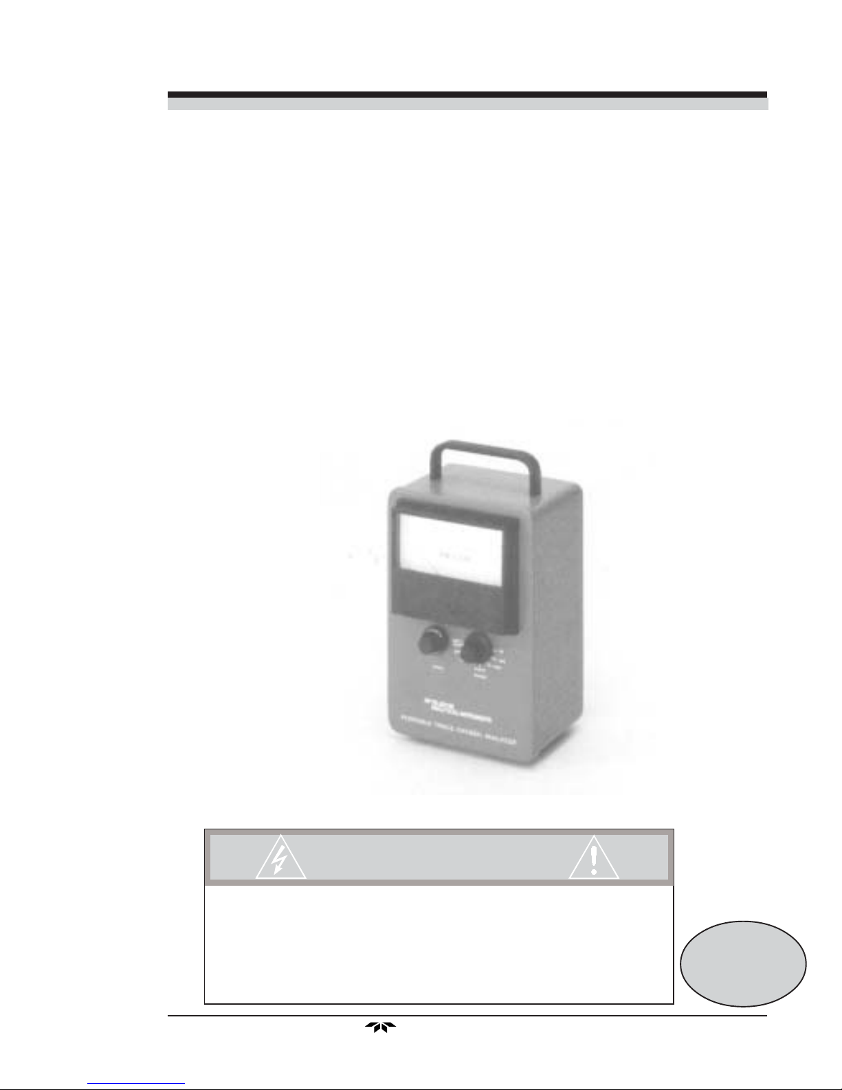
MODEL 311PC
PERCENT OXYGEN ANALYZER
HIGHLY TOXIC AND OR FLAMMABLE LIQUIDS OR GASES MAY BE PRESENT IN THIS MONITORING
SYSTEM.
PERSONAL PROTECTIVE EQUIPMENT MAY BE REQUIRED WHEN SERVICING THIS SYSTEM.
HAZARDOUS VOLTAGES EXIST ON CERTAIN COMPONENTS INTERNALLY WHICH MAY PERSIST FOR
A TIME EVEN AFTER THE POWER IS TURNED OFF AND DISCONNECTED.
ONLY AUTHORIZED PERSONNEL SHOULD CONDUCT MAINTENANCE AND/OR SERVICING. BEFORE
CONDUCTING ANY MAINTENANCE OR SERVICING CONSULT WITH AUTHORIZED SUPERVISOR/
MANAGER.
DANGER
Teledyne Analytical Instruments
P/N M61392
03/06/00
ECO # 00-0060
i

Percent Oxygen Analyzer Model
Copyright © 1999 Teledyne Analytical Instruments
All Rights Reserved. No part of this manual may be reproduced, transmitted,
transcribed, stored in a retrieval system, or translated into any other language or computer language in whole or in part, in any form or by any means, whether it be electronic, mechanical, magnetic, optical, manual, or otherwise, without the prior written
consent of Teledyne Analytical Instruments, 16830 Chestnut Street, City of Industry,
CA 91749-1580.
Warranty
This equipment is sold subject to the mutual agreement that it is warranted by us
free from defects of material and of construction, and that our liability shall be limited
to replacing or repairing at our factory (without charge, except for transportation), or at
customer plant at our option, any material or construction in which defects become
apparent within one year from the date of shipment, except in cases where quotations or
acknowledgments provide for a shorter period. Components manufactured by others
bear the warranty of their manufacturer. This warranty does not cover defects caused by
wear, accident, misuse, neglect or repairs other than those performed by Teledyne or an
authorized service center. We assume no liability for direct or indirect damages of any
kind and the purchaser by the acceptance of the equipment will assume all liability for
any damage which may result from its use or misuse.
311PC
We reserve the right to employ any suitable material in the manufacture of our
apparatus, and to make any alterations in the dimensions, shape or weight of any parts,
in so far as such alterations do not adversely affect our warranty.
Important Notice
This instrument provides measurement readings to its user, and serves as a tool by
which valuable data can be gathered. The information provided by the instrument may
assist the user in eliminating potential hazards caused by his process; however, it is
essential that all personnel involved in the use of the instrument or its interface, with the
process being measured, be properly trained in the process itself, as well as all instrumentation related to it.
The safety of personnel is ultimately the responsibility of those who control
process conditions. While this instrument may be able to provide early warning of
imminent danger, it has no control over process conditions, and it can be misused. In
particular, any alarm or control systems installed must be tested and understood, both as
to how they operate and as to how they can be defeated. Any safeguards required such
as locks, labels, or redundancy, must be provided by the user or specifically requested of
Teledyne at the time the order is placed.
Therefore, the purchaser must be aware of the hazardous process conditions.
The purchaser is responsible for the training of personnel, for providing hazard warning
methods and instrumentation per the appropriate standards, and for ensuring that hazard
warning devices and instrumentation are maintained and operated properly.
Teledyne Analytical Instruments (TAI, the manufacturer of this instrument,
cannot accept responsibility for conditions beyond its knowledge and control. No
statement expressed or implied by this document or any information disseminated by the
manufacturer or its agents, is to be construed as a warranty of adequate safety control
under the user’s process conditions.
ii
Teledyne Analytical Instruments

Percent Oxygen Analyzer Model 311PC
T able of Contents
1 Introduction
1.1 Description...................................................................1-1
1.2 Method of Analysis ......................................................1-1
1.3 Outstanding Features .................................................. 1-2
2 Installation
2.1 Sampling Equipment....................................................2-1
2.2 Power Service..............................................................2-1
3 Operation
3.1 Introduction..................................................................3-1
3.2 Cell Installation .............................................................3-1
3.3 Positive Pressure Sampling.........................................3-2
3.4 Atmospheric Pressure Sampling..................................3-2
3.5 Calibration ...................................................................3-3
3.4.1 Calibration Procedure Using Air ....................3 -3
3.4.2 Calibration Procedure Using Calibration Gas 3- 4
4 Maintenance
4.1 Battery Power Supply Service .....................................4- 1
4.2 Routine Maintenance...................................................4 -2
4.3 Cell Replacement ........................................................ 4-2
4.4 Cell Warranty ............................................................... 4-3
4.5 Transduction and Temperature Compensation............4-3
Appendix
Specifications......................................................................A-1
Recommended Spare Parts List for Model 311PC.............A-2
Drawing List ........................................................................A-2
Material Safety Data Sheet .................................................A-3
Teledyne Analytical Instruments
iii

Percent Oxygen Analyzer Model
311PC
iv
Teledyne Analytical Instruments

Percent Oxygen Analyzer Introduction 1
Introduction
1.1 Description
The Teledyneg Analytical Instruments (TAI) Model 311PC is a portable, intrinsically safe percent oxygen analyzer which can be operated
without an external power source and reliably calibrated without the use of
cumbersome, questionable, so-called “certified” calibration gases.
The instrument provides for percent oxygen analysis in the ranges
0–25%, 0–10%, 0–5%, 0–2.5% and 0–1% oxygen.
Sample oxygen is read from an extremely accurate integral meter
(0.5% linearity) whose range of measurement is determined by the position
of the range selector switch. The 0–2.5% range is read on the 0–25% scale
and the 0–1% range is read on the 0–10% scale. The linear 4.5 inch scale
(mirror equipped to eliminate parallax) provides excellent resolution and
accuracy.
Sample gas is introduced and vented via a pair of quick disconnect
fittings that feature integral shutoff valves which automatically close when
the mating male fitting is withdrawn. The fittings are an integral part of the
measuring cell manifold so that internal sample passage volume is at an
absolute minimum. Sample flow control, although not critical (0.1 to 10
liters/min.), must be accomplished with accessory equipment.
1.2 Method of Analysis
The sample oxygen is measured by a unique electrochemical transducer
which functions as a fuel cell; in this instance, the fuel is oxygen. Oxygen
diffusing into the cell reacts chemically to produce an electrical current that
is proportional to the oxygen concentration in the gas phase immediately
adjacent to the transducers sensing surface. The linear signal produced by
the transducer is amplified by a two stage amplifier. The dual stages of
amplification provide enough gain to drive the 0-100 microampere meter
and thermistor controlled network utilized to compensate for the positive
temperature coefficient of the transducer.
Teledyne Analytical Instruments
1–1

1 Introduction Model 311PC
1.3 Outstanding Features
The following unique features are incorporated into the Model
311PC:
• Micro-Fuel Cell
The Micro-fuel Cell (U.S. Pat. Nos. 3,767,552 and 3,668,101) is
a sealed electrochemical transducer with no electrolyte to change
or electrodes to clean. When the cell reaches the end of its
useful life, it is merely thrown away and replaced, as one would
replace a worn out battery in a flashlight. The life of the cell is
warranted by TAI (see Section 4.4) in a fashion similar to that
employed by the manufacturers of automobile batteries. This
procedure guarantees the customer compensation for failure of a
given cell to perform as specified.
• Reliable Calibration
The unique qualities of the Micro-fuel Cell allows the user to
calibrate the instrument with the most economical, reliable,
abundant, standardization gas there is — atmospheric air.
The 0–25% range should be used for air calibration; the
indicator needle of the meter is brought into coincidence with
the cal mark at 20.9% during air calibration. By drawing air
through the instrument (see the sample calibration procedure in
Section 3.2) reliable calibration can be achieved.
The electronics have been properly zeroed (a onetime factory
operation), so that the instrument does not produce an output
indication in the absence of oxygen. Refer to Section 3.2 if
readjustment is required.
• Integral Power Supply
The differential power requirement (plus and minus 3.6 volts
D.C.) of the instrument amplifier is furnished by two internally
mounted 750 milliampere hour nickel cadmium batteries. Fully
charged, these batteries will provide enough power to operate
the instrument continuously for a period of about thirty-five (35)
days. Furthermore, an overnight charge on a one-month duty
cycle should keep the original batteries supplied usable for many
years.
1–2
Teledyne Analytical Instruments

Percent Oxygen Analyzer Introduction 1
An integral charging circuit and a detectable power cord are
provided so that the batteries may be recharged from any 50 or
60 cycle, 105 to 125V (or with option, 220/240V) convenience
outlet.
The instrument is designed to either sample or have its batteries
recharged. Both operations cannot be carried out
simultaneously. TAI has deliberately interlocked the circuitry so
that both operations cannot be carried on at the same time.
Only when the selector switch is placed in the OFF position will
the neon lamp on the back plate of the Model 311PC light up to
indicate power to the battery charging circuit.
A current limiting resistor is potted into the end of each battery.
This assures that under no circumstances can more than 25
milliamperes (100 milliwatts) be switched or drawn from either
battery supply. This means that the Model 311PC may be used
in explosive atmospheres where arcs of 100 milliwatts or less
can be tolerated. The Model 311PC meets CENELEC approval
requirements as intrinsically safe for Group IIC Temperature
Class T4, hazardous locations as approved by BASEEFA
EX86B2228/3.
CAUTION: This safety feature does not apply when the instrument is being
charged (AC power cord connected and selector switch in the
“OFF” position). The instrument should not be used in explosive atmospheres when the batteries are being charged.
To determine the state of the rechargeable batteries, turn the
range selector knob counterclockwise to the battery test position
and hold there. The knob is a spring loaded switch. Observe that
the meter indicator stays within the battery limits. If it does not,
then recharge or replace the batteries. Release the Range
Selector Switch, it will automatically return to the OFF position.
• Accuracy and Response
The Model 311PC provides monitoring accuracies of ±2% of
full scale at constant temperature. A ±5% of full scale accuracy
is achievable throughout the operating temperature range of 0 to
50°C.
With a sample flowrate of 1–2 liters/min. 90% response is
achieved in 10 seconds.
Teledyne Analytical Instruments
1–3

1 Introduction Model 311PC
• Compact Packaging
The instrument is housed in 6-1/8 X 9-1/2 X 5-5/8 in aluminum
case that is equipped with a carrying handle and foot pads.
When in use, the analyzer should be placed in an upright position
on a level surface (off level positioning will detract from meter
accuracy).
Access to the instrument interior is gained by loosening (ccw)
the three (3) 1/4 turn screw driver type fasteners on the back of
the outer case. The case may then be detached from the control
panel assembly. Further disassembly may be accomplished by
removing the back plate assembly from its four (4) mounting
standoffs and laying the two separated assemblies out as
illustrated on the analyzer wiring diagram. The diagram is
included among the drawings at the rear of the manual.
• Analysis Ranges
This instrument is equipped with 5 oxygen analysis ranges:
0–25%, 0–10%, 0–5%, 0–2.5% and 0–1% oxygen. The oxygen
concentrations are read from an accurate integral meter with
appropriate scales for the included analysis ranges.
Note: The 0–2.5% range is read on the 0–25% scale and the 0–1% range is
read on the 0–10% scale.
The orange tinted portion of the scale applies only to the 0–25%
range of analysis. It indicates an oxygen rich environment and a
region unsuitable for measurement using this instrument.
Caution: Do not use this instrument for analysis in oxygen rich environ-
ments. This instrument is approved as "intrinsically safe" only
when used in environments containing 21% oxygen or below.
1–4
Teledyne Analytical Instruments

T race Oxygen Analyzer Installation 2
Installation
2.1 Sampling Equipment
The customer must provide a means of controlling the pressure and
flowrate of the sample gas. For positive pressure applications, TAI suggests
a simple throttle valve installed in the sample line between the sample point
and the analyzer. The flowrate should be limited to between 0.1 and 10
liters/min.
For atmospheric pressure sampling, connect a pump and flow control
valve downstream from the analyzer and draw (rather than push) the sample
through the instrument.
TAI supplies three (3) male disconnect fittings with the instrument:
one for installation of the customer’s sample line; one to be used to open the
vent fitting of the instrument; and one (equipped with a plastic tube) for
drawing air through the unit for calibration purposes.
2.2 Power Service
A source of single phase, 105 to 125 volt, 50 or 60 Hz power, capable
of delivering a maximum of ¼ ampere of current will be periodically required to recharge the instrument’s battery power supply. An internationally
approved 3 wire detachable power cord is provided with the instrument and
should be stored in a safe place when not in use.
Teledyne Analytical Instruments
2-1

2 Installation Model 31 1PC
Teledyne Analytical Instruments2-2

Percent Oxygen Analyzer Operation 3
Operation
3.1 Introduction
The Model 311PC is supplied completely assembled and ready for
instant use. The Micro-fuel Cell is packaged separately and should be
installed prior to use (see Section 3.2). The integral shut-off valves in the
quick disconnect sample fittings, if not disturbed, will provide a seal from
oxygen in the air and extend the life of the Micro-Fuel cell when the instrument is not used for extended periods of time (week—months).
When the range selector is advanced from the “OFF” position, power
to the instruments circuitry is established. The meter will instantly respond
to the residual oxygen within the integral sample passages. Depending on
the length of time since the last usage occurred, the reading will be somewhere between 0 and 21%.
3.2 Cell Installation
No tools are required to install the cell in the instrument. Simply
unscrew (ccw) the plug at the bottom of the analyzer. Remove the new cell
from its package and carefully remove the shorting device.
Note: Do not touch the gold colored sensing surface of the cell. It is
covered with a delicate Teflon membrane that can be ruptured in
handling.
Place the cell on the end of the manifold plug so that the sensing
surface of the cell is in contact with the plug and the electrical contact plate
end of the cell is facing upwards. Insert the cell and plug in the manifold
cavity, and screw the plug back into place. Apply as much pressure as you
can with your fingers, but use no tools.
Teledyne Analytical Instruments
3–1

3 Operation Model 31 1PC
3.3 Positive Pressure Sampling
When connecting the instrument to a positive pressure sample source,
always proceed as follows:
1) Before making any connections to the instrument, establish a
flowrate in the sample line of from 0.1–10 liters/min using a
throttle valve between the positive pressure source and the
instrument inlet (1–2 liters/min is suggested).
2) Install the vent fitting first, and then the sample source fitting.
When disconnecting the instrument, reverse the procedure: source
fitting first, and then vent fitting.
The objective of the connection — disconnection procedure is to
refrain from pressurizing the manifold.
Note: If a flowing sample was connected to the manifold without the vent
fitting in place, the pressure in the manifold would rise and equilibrate to the sample pressure almost immediately.
In such a situation, depending on the magnitude of the sample pres-
sure, leaks in the manifold could result.
Caution: If the meter reads in the orange portion of the scale while on the
0–25% oxygen scale after being calibrated, turn off the instrument and disconnect the source fitting followed by the vent
fitting. This instrument is not approved for service in oxygen
rich (oxygen concentration greater than 21%) environments.
3.4 Atmospheric Pressure Sampling
If the sample is at atmospheric pressure (or slightly negative), a
sample pump will be required downstream from the analyzer. The inlet
side of the pump should also be equipped with a throttle valve so that
sample flow can be reduced to between 0.1 and 10 liters/min (1–2 liters/min
is suggested). If pump loading is a consideration, the inlet side of the pump
will have to include a bypass path that is open to the atmosphere through an
additional throttle valve. The sample path and bypass path may then be
balanced by manipulating the two valves, so that sample flow is within the
prescribed limits without loading the pump.
Note: Under no circumstances should there be any restrictions in the line
between the sample point and the analyzer.
3–2
Teledyne Analytical Instruments

Percent Oxygen Analyzer Operation 3
If this should occur, a partial vacuum would be drawn on the cell.
Since the cell is a partial pressure sensitive device, any oxygen readings
taken under these conditions would be erroneous. Pressure less than 0.3
atm. could damage the cell.
Caution: If the meter reads in the orange portion of the scale while on the
0–25% oxygen scale after being calibrated, turn off the instrument and disconnect the source fitting followed by the vent
fitting. This instrument is not approved for service in oxygen
rich (oxygen concentration greater than 21%) environments.
3.5 Calibration
The inherently constant output of the cell during its useful life eliminates the need for frequent calibration. TAI feels that the interval between
calibrations should be dictated by the customer’s application.
The Model 311PC should be calibrated using a span gas with a known
oxygen concentration. Ambient air (20.9% ) is recommended for calibration.
The analyzer can be calibrated on any range using a span gas. The span
gas concentration should be within 70% to 90% of full scale of the range
selected.
Note: Using a span gas with a concentration greater than 100% of full
scale will put you in the next range and result in a reduced accuracy.
3.4.1 Calibration Procedure Using Air
To calibrate the instrument with atmospheric air as a standard, use the
following procedure:
1) Stand the instrument upright on a level surface, and with the
range switch in the “OFF” position, check the alignment of the
meter pointer with the zero mark on the scale. Use the mirror to
eliminate parallax, and adjust the screw on the face of the meter,
if necessary, until the pointer and zero mark are in precise
coincidence.
2) Advance the range switch to the 0–25% position.
Teledyne Analytical Instruments
3–3

3 Operation Model 31 1PC
3) Install the plastic tube equipped male disconnect fitting in either
of the analyzer’s sample ports, and a blank disconnect fitting in
the other port (direction of sample flow is of no importance). A
pump is recommended on the plastic tube. Pump the tube until
the meter reading is stable.
CAUTION: Do not use your mouth as a siphon. The micro-fuel cell could
leak. This cell contains potassium hydroxide solution (KOH)
which is caustic and extremely hazardous.
4) Unlock and adjust the span control until the meter pointer is in
coincidence with the “CAL” mark on the meter scale (20.9%).
Note: Be sure that you relock the control after the adjustment is made.
5) Immediately after step 4 has been accomplished, disconnect the
tubing equipped calibration fitting, and plug in either the sample
or a source of zero gas.
If the instrument is to be used for sampling after the calibration procedure has been completed, follow the decreasing oxygen reading by positioning the range switch so that the meter gives the best possible resolution of
the oxygen. Do not attempt to take a reading until the meter indication
stabilizes.
Always disconnect the source fitting first followed by the vent
fitting.
3.4.2 Calibration Procedure Using Calibration Gas
To calibrate the instrument using a gas source with a known concentration of oxygen, select a calibration gas with an oxygen concentration
between 70–90% of full scale on the range of interest. For example, if you
anticipate your sample gas will contain 0–0.5% oxygen, obtain a calibration
gas with 0.7–0.9% oxygen and calibrate the instrument on the 0–1% range.
To calibrate the instrument using a lab analyzed calibration gas use the
following procedure:
1) Stand the instrument upright on a level surface, and with the
range switch in the “OFF” position, check the alignment of the
meter pointer with the zero mark on the scale. Use the mirror to
eliminate parallax, and adjust the screw on the face of the meter,
if necessary, until the pointer and zero mark are in precise
coincidence.
2) Advance the range switch to the range position containing the
concentration of the calibration gas.
3–4
Teledyne Analytical Instruments

Percent Oxygen Analyzer Operation 3
3) Connect the calibration gas to either of the instrument's sample
port using a quick disconnect fitting. Use a blank quick
disconnect fitting on the other port to open the seal.
Always connect the vent fitting first followed by the source
fitting.
The analyzer is insensitive to flow rate, however for calibration,
use a flow rate similar to the sample flow you will be using. If
the flow rate will vary or is unknown, use a flowrate between
1–2 liters per minute. Allow sample to flow for several minutes
to flush the sample line. Watch the output of the meter for the
reading to stabilize.
4) Unlock and adjust the span control until the meter pointer is in
coincidence with the concentration of the calibration gas.
Note: Be sure that you relock the control after the adjustment is made.
5) Immediately after step 4 has been accomplished, disconnect the
calibration source gas fitting at the analyzer sample port, and
plug in either the sample or a source of zero gas.
Always disconnect the source fitting first, immediately followed by
the vent fitting.
Teledyne Analytical Instruments
3–5

3 Operation Model 31 1PC
3–6
Teledyne Analytical Instruments

Percent Oxygen Analyzer Maintenance 4
Maintenance
4.1 Battery Power Supply Service
The Model 311PC is designed to be intrinsically safe, and therefore is
for use only when it is not connected to the AC power line. TAI suggest
that an overnight recharge be accomplished every four (4) weeks of continuous use. To recharge the batteries, place the range switch in the “OFF”
position and connect the power cord to a convenient outlet.
Note: The amber charge lamp (back of case) will be lit during charging.
The integral charging circuit will automatically energize and regulate
the battery charging current when the switch is in the “OFF” position and
the AC cord is plugged into the power line.
CAUTION: Do not turn the range switch either to "BATT TEST" or to any
other operating position while the unit is connected to a power
line. Doing so may damage the equipment.
When recharging is completed, unplug the unit from the AC outlet.
Turn the range switch to the operating position and then to the “BATT
TEST” position.
Note: The “BATT TEST” position will not give a reliable indication of the
battery charge immediately after a charge cycle. Allow the unit to
run for several minutes before testing the batteries.
In the "BATT TEST" position, the meter should indicate between the
6 and the 8 on the 0-25% scale.
If the instrument is stored with the range switch in the “OFF” position
(charge cord disconnected), the period of time between charge periods is
extended from one month to four months. However, do not leave it longer
than this time period.
Teledyne Analytical Instruments
4–1

4 Maintenance Model 31 1PC
4.2 Routine Maintenance
Beyond adhering to a battery recharge schedule, no routine maintenance is required, as there are no moving parts in the instrument other than
the meter movement. The Micro-fuel Cell is a sealed, modular component
that should be replaced only when faulty.
4.3 Cell Replacement
The characteristics of the Micro-fuel Cell are similar to those of a
mercury battery in that both provide an almost constant output through
their useful life, and then fall off sharply towards zero at the end. If the
sample being analyzed has a low oxygen concentration, cell failure will
probably be indicated by the inability to properly calibrate the analyzer. The
user will find that very little adjustment of the 10-turn span potentiometer
will be required to keep the analyzer calibrated properly during the duration
of a given cell’s useful life. If large, many turn adjustments (cw) are required to calibrate the instrument, or calibration cannot be achieved within
the range of the control, the cell should be immediately replaced (read
section 5.4 before replacing cell).
To offset the possibility of not having a replacement cell available
when it is needed, TAI recommends that a spare cell be purchased shortly
after the instrument is placed in service, and each time the cell is replaced
thereafter.
The spare cell should be carefully stored in an area that is not subject
to large variations in ambient temperature (75°F nominal), and in such a
way as to eliminate any possibility of incurring damage. Under no circum-
stances, disturb the integrity of the cell package until the cell is to be
actually used. If the cell package is punctured and air permitted to enter,
the cell will immediately start to react to the presence of oxygen.
No tools are required to replace the cell in the instrument. Simply
unscrew (ccw) the plug at the bottom of the analyzer and the cell will drop
out of the manifold cavity.
Remove the new cell from its package, and carefully remove the
shorting clip.
Note: Do not touch the gold colored sensing surface of the cell. It is
covered with a delicate Teflon membrane that can be ruptured in
handling.
4–2
Teledyne Analytical Instruments

Percent Oxygen Analyzer Maintenance 4
Place the cell on the end of the manifold plug so that the sensing
surface of the cell is in contact with the plug and the electrical contact plate
end of the cell is facing upwards. Insert the cell and plug in the manifold
cavity, and screw the plug back into place. Apply as much pressure as you
can with your fingers, but use no tools.
4.4 Cell Warranty
The Class B-1 cell employed in the Model 311PC is warranted for six
(6) months of service.
With regard to spare cells, service time starts when the cell is removed
from its shipping package. The customer should stock only one spare cell
per instrument at a time. Do not attempt to stockpile spare cells.
The Model 311PC should not be used in applications where CO2 is a
major component in the sample. Concentrations of 1,000 ppm or less will
not effect the cell performance. Figure 4-1 is a graph showing the effects of
CO2 on cell life.
If a cell was working satisfactorily, but ceases to function before the
warranty period expires, the customer will receive credit, on a prorated
basis, toward the purchase of a new cell.
If you have a warranty claims must return the cell in question to the
factory for evaluation. If it is determined that failure is due to faulty workmanship or material, the cell will be replaced at no cost to the customer.
Note: Evidence of damage due to tampering or mishandling will render
the cell warranty null and void.
4.5 Transduction and Temperature
Compensation
The Micro-Fuel Cell has an inherent positive temperature coefficient,
the effects of which have been minimized through the implementation of a
calibrated thermistor compensation circuit.
Internal electronic calibration is accomplished by TAI. However,
should there be any doubt concerning it, the following procedure can be
used to recalibrate. Refer to the schematic.
1. Disconnect cell
2. Move range switch to “cal” position.
Teledyne Analytical Instruments
4–3

4 Maintenance Model 31 1PC
8
10
% Carbon Dioxide
Predict ed Weeks of Cell Life
Notes:
1. This curve assumes continuous exposure.
9
2. Intermittent exposure will extend life. In general,
the CO2 effect is cumulative and the average CO
2
concentration should be used to find the predicted
cell life.
8
3. Cells can be used to make spot check
measurements of O2 in the presence of high
concentrations of CO2 (up to 50% and more). The
7
CO2 containing sample should be purged out as
soon as a constant reading is obtained.
4. Abnormally slow response and recovery is
6
characteristic of cells operated as indicated in
notes 1, 2, and 3.
5
5. The reduction in cell life is primarily due to a
drop in output. This reduces to a point where the
instrument can no longer be spanned. Instruments
using B-1 cells in CO2 atmospheres should be
4
spanned more frequently (at intervals 10-20% of
the predicted life).
6. The CO2 effect on B-1 cells is independent of the
3
O2 level. The reduction in cell life due to their
being used in CO2 atmospheres is therefore
limiting and takes precedence over the normal
4–4
0,0
2
1
4
Figure 4-1: The Effect of CO2 on B-1 Cell Life
8
Teledyne Analytical Instruments
warranty.
12 16 20
24
2

Percent Oxygen Analyzer Maintenance 4
3. Adjust R1 (designated as R1 on schematic C37936 and
designated on the A1 PCB module assembly as R28) such that
the output of A1, pin 6, measures between 0 and +0.5 mV,
ideally +0.3 mV.
4. Adjust R2 (designated as R2 on schematic C37936 and
designated on the A3 PCB module assembly as R28) for 0 + 1
mV at output of A2, pin 6.
5. Verify that the offset is the same on all ranges.
6. Reconnect cell.
Teledyne Analytical Instruments
4–5

4 Maintenance Model 31 1PC
4–6
Teledyne Analytical Instruments

Percent Oxygen Analyzer Appendix
Appendix
Specifications
TBE/AI Sales Order Number:
Instrument Model Number: 311PC
Instrument Serial Number:
Micro-fuel Cell Class: B-1
Accuracy: ±2% of scale at constant temperature;
±5% of full scale over the operating
temperature range.
Operating Temperature Range: 30oF to 125oF
Response and Recovery: At the specified flowrate (1–2 l/min)
90% in 10 seconds.
Ranges of Analysis: 0–25% Oxygen
0–10% Oxygen
0–5% Oxygen
0–2.5% Oxygen
0–1% Oxygen
Recommended Span Gas: Atmospheric air, or span gas 70–90%
of full scale on range of interest.
Teledyne Analytical Instruments
A–1

Appendix Model 311PC
Recommended Spare Parts List for
Model 311PC
QTY PART NO. DESCRIPTION
1 F1122 IEC Fuse, 1/4 Amp. (for 220V units)
1 F1123 IEC Fuse, 1/2 Amp. (for 110V units)
1 C06689-B1 Micro-fuel Cell, Class B-1
2 B-9905 Battery
1 L79 Lamp
A minimum charge is applicable to spare parts orders.
IMPORTANT: Orders for replacement parts should include the part number
(if available) and the model and serial number of the system
for which the parts are intended.
Send Orders to:
Teledyne Analytical Instruments
16830 Chestnut St.
City of Industry, CA 91749-1580
Phone (626)934-1500, FAX (626)961-2538
Web: www.teledyne-ai.com
Drawing List
Model 311PC
C-62685 Pictorial Diagram
C-37936 Schematic
C-37938 Wiring Diagram (220V)
C-41661 Wiring Diagram (110V)
A–2
Teledyne Analytical Instruments

Percent Oxygen Analyzer Appendix
NOTE: The MSDS on this material is available upon request
through the Teledyne Environmental, Health and
Safety Coordinator. Contact at (626) 934-1592
Teledyne Analytical Instruments
A–3

Appendix Model 311PC
A–4
Teledyne Analytical Instruments

Percent Oxygen Analyzer Appendix
Material Safety Data Sheet
Section I – Product Identification
Product Name: Micro-Fuel Cells
Mini-Micro-Fuel Cells, all classes
Super Cells, all classes except T–5F
Electrochemical Oxygen Sensors, all classes.
Manufacturer: Teledyne Electronic Technologies/Analytical Instruments
Address: 16830 Chestnut Street, City of Industry, CA 91748
Phone: (626) 934-1500
Technical Support: (626) 934-1673
Environment Health
and Safety: (626) 934-1592
Date Prepared : 10/19/98
Section II – Ph ysical and Chemical Data
Chemical and Common Names: Potassium Hydoxide (KOH), 15% (w/v)
Lead (Pb), pure
CAS Number: KOH 1310–58–3
Pb 7439–92–1
KOH (15% w/v) Pb (pure)
Melting Point/Range: –10 to 0 °C 328 °C
Boiling Point/Range: 100 to 115 °C 1744 °C
Specific Gravity: 1.09 @ 20 °C 11.34
pH: >14 N/A
Solubility in Water: Completely soluble Insoluble
Percent Volatiles by Volume: None N/A
Appearance and Odor: Colorless, odorless solution Grey metal,
odorless
Teledyne Analytical Instruments
A–5

Appendix Model 311PC
Section III – Physical Hazards
Potential for fire and explosion: The electrolyte in the Micro-Fuel Cells is
not flammable. There are no fire or explosion hazards associated with Micro-Fuel Cells.
Potential for reactivity: The sensors are stable under normal conditions of
use. Avoid contact between the sensor electrolyte and strong acids.
Section IV – Health Hazard Data
Primary route of entry: Ingestion, eye/skin contact
Exposure limits:OSHA PEL: .05 mg/cu.m. (Pb)
ACGIH TLV: 2 mg/cu.m. (KOH)
Effects of overexposure
Ingestion: The electrolyte could be harmful or fatal
if swallowed.
Oral LD50 (RAT) = 3650 mg/kg
Eye: The electrolyte is corrosive; eye contact
could result in permanent loss of vision.
Dermal: The electrolyte is corrosive; skin contact
could result in a chemical burn.
Inhalation: Liquid inhalation is unlikely.
Signs/symptoms of exposure: Contact with skin or eyes will cause a
burning sensation and/or feel soapy or
slippery to touch.
Medical conditions
aggravated by exposure: None
Carcinogenicity: NTP Annual Report on Carcinogens: Not
listed
LARC Monographs: Not listed
OSHA: Not listed
Other health hazards: Lead is listed as a chemical known to the
A–6
Teledyne Analytical Instruments
State of California to cause birth defects
or other reproductive harm.

Percent Oxygen Analyzer Appendix
Section V – Emergency and First Aid Procedures
Eye Contact: Flush eyes with water for at least 15 minutes and get im-
mediate medical attention.
Skin Contact: Wash affected area with plenty of water and remove con-
taminated clothing. If burning persists, seek medical
attention.
Ingestion: Give plenty of cold water. Do not induce vomiting. Seek
medical attention. Do not administer liquids to an unconscious person.
Inhalation: Liquid inhalation is unlikely.
Section VI – Handling Inf ormation
NOTE: The oxygen sensors are sealed, and under normal circumstances,
the contents of the sensors do not present a health hazard. The
following information is given as a guide in the event that a cell
leaks.
Protective clothing: Rubber gloves, chemical splash goggles.
Clean-up procedures: Wipe down the area several times with a wet pa-
per towel. Use a fresh towel each time.
Protective measures
during cell replacement:Before opening the bag containing the sensor
cell, check the sensor cell for leakage. If the sensor cell leaks, do not open the bag. If there is
liquid around the cell while in the instrument, put
on gloves and eye protection before removing the
cell.
Disposal: Should be in accordance with all applicable state,
local and federal regulations.
NOTE: The above information is derived from the MSDS provided by the
manufacturer. The information is believed to be correct but does
not purport to be all inclusive and shall be used only as a guide.
Teledyne Analytical Instruments shall not be held liable for any
damage resulting from handling or from contact with the above
product.
Teledyne Analytical Instruments
A–7

Appendix Model 311PC
A–8
Teledyne Analytical Instruments
 Loading...