

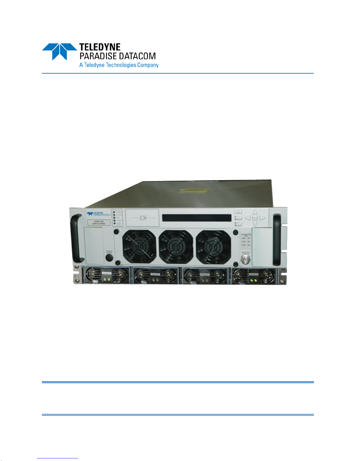
3 RU Chassis
Solid State Power Amplifier
Operations Manual
Teledyne Paradise Datacom Phone: (814) 238-3450
328 Innovation Blvd., Suite 100 Fax: (814) 238-3829
State College, PA 16803 USA Web: www.paradisedata.com
Email: sales@paradisedata.com
205356 REV T ECO 18284 08/09/2017

Teledyne Paradise Datacom, a division of Teledyne Wireless LLC, is a single source for high power
solid state amplifiers (SSPAs), Low Noise Amplifiers (LNAs), Block Up Converters (BUCs), and Modem
products. Operating out of two primary locations, Witham, United Kingdom, and State College, PA, USA,
Teledyne Paradise Datacom has a more than 20 year history of providing innovative solutions to enable
satellite uplinks, battlefield communications, and cellular backhaul.
Teledyne Paradise Datacom Teledyne Paradise Datacom Ltd.
328 Innovation Blvd., Suite 100 2&3 The Matchyns, London Road, Rivenhall End
State College, PA 16803 USA Witham, Essex CM8 3HA England
(814) 238-3450 (switchboard) +44 (0) 1376 515636
(814) 238-3829 (fax) +44 (0) 1376 533764 (fax)
Information in this document is subject to change without notice. The latest revision of this document
may be downloaded from the company web site: http://www.paradisedata.com.
Use and Disclosure of Data
The items described herein are controlled by the U.S. Government and authorized for export only to the
country of ultimate destination for use by the ultimate consignee or end-user(s) herein identified. They
may not be resold, transferred, or otherwise disposed of, to any other country or to any person other
than the authorized ultimate consignee or end-user(s), either in their original form or after being
incorporated into other items, without first obtaining approval from the U.S. government or as otherwise
authorized by U.S. law and regulations.
Proprietary and Confidential
The information contained in this document is the sole property of Teledyne Paradise Datacom. Any
reproduction in part or as a whole without the written permission of Teledyne Paradise Datacom is
prohibited.
All other company names and product names in this document are property of the respective
companies.
© 2017 Teledyne Paradise Datacom
Printed in the USA
2 205356 REV T 3 RU SSPA Chassis Operations Manual

Table of Contents
Section 1: General Information ............................................................................................. 11
1.0 Introduction ............................................................................................................. 11
1.1 Description .............................................................................................................. 11
1.2 Specifications .......................................................................................................... 12
1.3 Equipment Supplied ................................................................................................ 12
1.4 Inspection ................................................................................................................ 12
1.5 Rack Mounting ........................................................................................................ 12
1.6 Shipment ................................................................................................................. 12
1.7 Safety Considerations ............................................................................................. 12
1.7.1 High Voltage Hazards .............................................................................. 13
1.7.2 High Current Hazards .............................................................................. 13
1.7.3 RF Transmission Hazards ........................................................................ 14
1.7.4 Electrical Discharge Hazards ................................................................... 14
1.7.5 High Potential for Waveguide Arcing ....................................................... 14
1.8 Waveguide Pressurization and Dehydration ........................................................... 15
Section 2: Operation of Stand-Alone Unit ............................................................................ 19
2.0 Introduction ............................................................................................................. 19
2.1 Description of Controls, Indicators and Connectors ................................................ 19
2.1.1 Front Panel Features ............................................................................... 19
2.1.1.1 Fault Condition LEDs................................................................. 19
2.1.1.2 Standby Select Key .................................................................. 19
2.1.1.3 Front Panel Display ................................................................... 20
2.1.1.4 Navigation Keys ........................................................................ 20
2.1.1.5 Main Menu Key ........................................................................ 20
2.1.1.6 Local/Remote Key .................................................................... 20
2.1.1.7 Mute/Unmute Key ..................................................................... 20
2.1.1.8 Input Sample Port (Optional) [N-type (F)] .................................. 20
2.1.1.9 Output Sample Port (N-type (F)) ............................................... 20
2.1.1.10 Removable Fan Assembly ...................................................... 20
2.1.1.11 Removable Power Supply Modules......................................... 21
2.1.1.12 Front Panel Power Switch (Optional) ...................................... 21
2.1.2 Rear Panel Features ................................................................................ 21
2.1.2.1 AC Input Port (J10) [IEC 6100-3300 (F)] ................................... 21
2.1.2.2 DC Input with N+1 External Power Supply (J10) (Option) ......... 22
2.1.2.3 R3 Input Port (J1) [Type N (F)] .................................................. 24
2.1.2.4 RF Output Port (J2) [Band specific] ........................................... 24
2.1.2.5 Switch Port (J3) [6-pin MS-type] ................................................ 24
2.1.2.6 Serial Main (J4) [DB9 (F)] .......................................................... 25
2.1.2.7 Serial Local (J5) [DB9 (M)] ........................................................ 25
2.1.2.8 Program Port (J6) [DB25 (M)] .................................................... 25
2.1.2.9 Parallel I/O (J7) [DB37 (F)] ........................................................ 25
2.1.2.9.1 Hardware Mute (Tx Enable) ........................................ 27
2.1.2.10 Link Port (J8) [DB9 (M)] ........................................................... 27
2.1.2.11 Ethernet Port (J9) [RJ45] ......................................................... 27
2.1.2.12 Removable Fan Assembly ...................................................... 28
3 RU SSPA Chassis Operations Manual 205356 REV T 3

2.2 Menus ..................................................................................................................... 28
2.2.1 System Information Sub-Menu ................................................................. 29
2.2.1.1 Sys Info Page 1 ......................................................................... 30
2.2.1.1.1 Clear Faults Menu ...................................................... 30
2.2.1.2 Sys Info Page 2 ......................................................................... 31
2.2.1.3 Sys Info Page 3 ......................................................................... 31
2.2.1.4 Sys Info Page 4 ......................................................................... 31
2.2.1.5 Sys Info Page 5 ......................................................................... 32
2.2.1.6 Sys Info Page 6 ......................................................................... 32
2.2.1.7 Sys Info Page 7 ......................................................................... 32
2.2.1.8 Sys Info Page 8 ......................................................................... 33
2.2.1.9 Sys Info Page 9 (version 6.00) .................................................. 33
2.2.1.10 Sys Info Page 10 (version 6.00) .............................................. 34
2.2.1.11 IP Info Page 1 .......................................................................... 35
2.2.1.12 IP Info Page 2 .......................................................................... 35
2.2.1.13 IP Info Page 3 .......................................................................... 35
2.2.1.14 IP Info Page 4 .......................................................................... 36
2.2.1.15 Firmware Info Page 1 .............................................................. 36
2.2.1.16 Firmware Info Page 2 (version 4.0) ......................................... 36
2.2.1.17 Firmware Info Pages 3, 4, 5, 6 and 7 (version 4.0) ................. 36
2.2.1.18 Hardware Info Page 8 (version 6.00)....................................... 36
2.2.1.19 HPA Local Time Page 9 (version 6.00) ................................... 36
2.2.1.20 HPA Run Time Page 10 (version 6.00) ................................... 37
2.2.1.21 N+1 Master Info Page 1 .......................................................... 37
2.2.1.21.1 Clear Faults Menu .................................................... 38
2.2.1.22 N+1 Slave Info Page ............................................................... 38
2.2.1.22.1 Clear Faults Menu .................................................... 38
2.2.1.23 N+1 Master Info Page 2 .......................................................... 39
2.2.1.24 N+1 Master Info Page 3 .......................................................... 39
2.2.2 Communication Setup Sub-Menu ............................................................ 40
2.2.2.1 Protocol ..................................................................................... 40
2.2.2.2 Baud Rate ................................................................................. 40
2.2.2.3 System Address ........................................................................ 41
2.2.2.4 Interface .................................................................................... 41
2.2.2.5 IP Setup ..................................................................................... 41
2.2.2.5.1 More (SNMP, IP and Web Settings) ....................................... 42
2.2.2.5.2 More (Traps and Time Settings) ............................................. 43
2.2.2.6 N+1 Control (Floating Master Mode) ......................................... 44
2.2.3 Operation Setup Sub-Menu ..................................................................... 46
2.2.3.1 Info ............................................................................................ 46
2.2.3.2 Buzzer ....................................................................................... 46
2.2.3.3 Mute .......................................................................................... 46
2.2.3.4 Sys. Mode ................................................................................. 46
2.2.3.5 Attenuation ................................................................................ 47
2.2.3.6 RF Units .................................................................................... 47
2.2.4 Fault Monitoring Setup Sub-Menu ........................................................... 48
2.2.4.1 BUC Fault .................................................................................. 48
2.2.4.2 Auxiliary Faults .......................................................................... 48
2.2.4.3 RF Switch Faults ....................................................................... 49
2.2.4.4 Fault Latch ................................................................................. 49
4 205356 REV T 3 RU SSPA Chassis Operations Manual

2.2.4.5 Forward RF / Automatic Level Control ...................................... 49
2.2.4.5.1 Disable ........................................................................ 49
2.2.4.5.2 Low RF ....................................................................... 49
2.2.4.5.3 High RF....................................................................... 50
2.2.4.5.4 ALC On (Automatic Level Control) ............................. 50
2.2.4.5.5 Set Level ..................................................................... 51
2.2.4.5.6 Back ............................................................................ 51
2.2.5 Options Sub-Menu ................................................................................... 52
2.2.5.1 Backup User Settings ................................................................ 52
2.2.5.2 Restore ...................................................................................... 52
2.2.5.3 Lamp Test ................................................................................. 53
2.2.5.4 Password ................................................................................... 53
2.2.5.5 Fan Speed ................................................................................. 53
2.2.5.6 Reset ......................................................................................... 54
2.2.6 Redundancy Sub-Menu ........................................................................... 55
2.2.6.1 Switching ................................................................................... 55
2.2.6.2 Standby Select .......................................................................... 55
2.2.6.3 Standby Mode ........................................................................... 55
2.2.6.4 Status ........................................................................................ 55
2.2.6.5 Priority ....................................................................................... 56
2.2.6.6 N+1 System Operation Parameters .......................................... 56
2.2.6.6.1 N+1 Array Size ........................................................... 56
2.2.6.6.2 N+1 Address ............................................................... 56
2.2.6.6.3 Auto Gain Control ....................................................... 56
2.2.6.6.4 N+1 Info ...................................................................... 57
2.2.6.6.5 Module Eject ............................................................... 58
2.2.6.6.6 Back ............................................................................ 58
2.3 N+1 Operational Basics (Single Unit) ..................................................................... 59
2.4 N+1 Operational Basics (Two or More Units) ......................................................... 59
2.4.1 Selecting the Master Module .................................................................... 59
2.4.2 Controlling System Operation .................................................................. 60
2.4.3 N+1 Addressing ........................................................................................ 61
2.4.4 Adjust System Gain .................................................................................. 61
2.4.5 N+1 Automatic Gain Control Option ......................................................... 61
2.4.6 N+1 RF Power Measurements ................................................................. 62
2.4.7 N+1 Fault Detection ................................................................................. 62
2.5 Reflected Power Option .......................................................................................... 64
2.5.1 Reflected Power Alarm ............................................................................ 64
Section 3: Troubleshooting and Maintenance ..................................................................... 65
3.0 Troubleshooting Faults ........................................................................................... 65
3.0.1 Summary Fault ......................................................................................... 65
3.0.2 Voltage Fault ............................................................................................ 65
3.0.3 Temperature Fault .................................................................................... 65
3.0.4 Current Fault ............................................................................................ 66
3.0.5 Power Supply Fault .................................................................................. 66
3.0.6 Fan Fault .................................................................................................. 66
3.0.7 Low RF Fault ............................................................................................ 67
3.1 Modular SSPA Architecture .................................................................................... 68
3.1.1 Removable Fans (Intake and Exhaust) .................................................... 68
3 RU SSPA Chassis Operations Manual 205356 REV T 5

3.1.1.1 Fan and Heatsink Maintenance ................................................. 69
3.1.2 SSPA Module Removal ............................................................................ 70
3.1.3 Power Supply Module Removal ............................................................... 71
3.1.3.1 External N+1 Redundant Power Supply .................................... 71
3.1.4 Removable Controller Card (Rear Panel) ................................................ 72
3.1.3 Firmware Upgrade Procedure .................................................................. 73
3.1.3.1 Required Hardware ................................................................... 73
3.1.3.2 Required Software ..................................................................... 73
3.1.3.3 Web Upgrade Procedure ........................................................... 74
3.1.3.4 USB Port Upgrade Procedure ................................................... 76
3.2 Changing N+1 Hierarchy ......................................................................................... 77
3.2.1 Changing Hierarchical Order of Slave Units............................................. 77
3.2.2 Exchange N+1 Privileges Between Master and Slave Units .................... 77
3.2.3 Add an SSPA Unit to the System ............................................................. 78
Section 4: Operation of a 1:1 Redundant System .............................................................. 79
4.0 Introduction ............................................................................................................. 79
4.1 Hardware ................................................................................................................ 80
4.1.1 Power Supply ........................................................................................... 81
4.1.2 RF Switch ................................................................................................. 81
4.1.3 Switch Connector ..................................................................................... 81
4.1.4 Link Cable ................................................................................................ 82
4.2 Installation and SSPA configuration ....................................................................... 83
4.2.1 Configuring HPA to Work in 1:1 Redundant Mode (Internal Control) ....... 83
4.2.1.1 Setting SSPA1 to Work in 1:1 Mode .......................................... 83
4.2.1.2 Setting SSPA1 Switching Mode ................................................ 84
4.2.1.3 Setting SSPA1 Unit Status ........................................................ 84
4.2.2 Online / Standby Amplifier Selection ........................................................ 84
4.2.3 Auto Versus Manual Switching Mode ...................................................... 85
4.2.4 Physically Rotating Transfer Switch ......................................................... 85
4.2.5 Switchover Muting .................................................................................... 85
4.2.6 Parallel Port Special Functions ................................................................ 86
Section 5: Operation of a 1:2 Internal Redundant System ................................................ 87
5.0 Introduction ............................................................................................................. 87
5.1 Required Hardware ................................................................................................. 88
5.2 Power Supply .......................................................................................................... 89
5.3 RF Switches ............................................................................................................ 89
5.4 Switch Connector .................................................................................................... 89
5.5 Link Cable ............................................................................................................... 90
5.6 Installation and SSPA Configuration ....................................................................... 92
5.6.1 Installation ................................................................................................ 92
5.6.1.1 Configuring HPA to Work in 1:2 Mode (Internal Control) ........... 92
5.6.1.2 Setting HPA1 Switching Mode................................................... 92
5.6.1.3 Setting HPA1 Unit Status .......................................................... 92
5.6.2 Setting SSPA’s Polarization Priority ......................................................... 93
5.7 Online/Standby Amplifier Selection ......................................................................... 93
5.8 Auto Versus Manual Switching Mode ..................................................................... 94
5.9 Physically Rotating Transfer Switch ........................................................................ 94
5.10 Parallel Port Special Functions ............................................................................. 94
6 205356 REV T 3 RU SSPA Chassis Operations Manual

Section 6: L-Band Operation ................................................................................................. 95
6.0 Block Up Converter Overview ................................................................................. 95
6.1 ZBUC Converter Features ...................................................................................... 97
6.2 ZBUC Converter Theory of Operation .................................................................... 97
6.3 Smart Reference Technology ................................................................................. 98
6.3.1 Specifications for Internal Crystal Reference ........................................... 98
6.4 Typical System Configuration ................................................................................. 99
6.5 IFL Cable Considerations ....................................................................................... 99
Section 7: Remote Control Interface ................................................................................... 101
7.0 Overview ............................................................................................................... 101
7.1 Remote Control - Parallel ..................................................................................... 103
7.1.1 Control Outputs ..................................................................................... 103
7.1.2 Control Inputs ........................................................................................ 103
7.2 Serial Communication Protocol ............................................................................. 104
7.2.1 Header Sub-Packet ................................................................................ 104
7.2.1.1 Frame Sync Word ................................................................... 104
7.2.1.2 Destination Address ................................................................ 104
7.2.1.3 Source Address ....................................................................... 104
7.2.2 Data Packet ............................................................................................ 105
7.2.2.1 Protocol ID ............................................................................... 105
7.2.2.2 Request ID .............................................................................. 105
7.2.2.3 Command ................................................................................ 105
7.2.2.4 Data Tag .................................................................................. 106
7.2.2.5 Error Status / Data Address..................................................... 106
7.2.2.6 Data Length ............................................................................. 107
7.2.2.7 Data Field ................................................................................ 107
7.2.3 Trailer Packet ......................................................................................... 108
7.2.3.1 Frame Check ........................................................................... 108
7.2.4 Timing issues ......................................................................................... 108
7.2.5 Serial Communications Protocol ............................................................ 109
7.3 Access SSPA Subsystem through Packet Wrapper Technique ........................... 115
7.4 Example 1 Check SSPA settings .......................................................................... 116
7.5 Terminal Mode Serial Protocol for Paradise Datacom SSPA ............................... 118
7.6 Ethernet Interface ................................................................................................. 120
7.6.1 IPNet Interface ....................................................................................... 120
7.6.1.1 General Concept ..................................................................... 120
7.6.1.2 Setting IPNet Interface ............................................................ 122
7.6.1.3 Using the Rack Mount Web Interface ...................................... 123
7.6.2 SNMP Interface ...................................................................................... 125
7.6.2.1 Interface .................................................................................. 125
7.6.2.2 SNMP V3 Issues in Teledyne Paradise Datacom SSPAs ....... 125
7.6.2.3 SNMP MIB tree ....................................................................... 128
7.6.2.4 Description of MIB Entities ...................................................... 129
7.6.2.5 Configuring SSPA to Work with SNMP Protocol ..................... 134
7.6.2.6 Connecting to a MIB Browser .................................................. 135
7.6.3 Extended SNMP Operation .................................................................... 137
7.6.3.1 Extended SNMP MIB Tree ...................................................... 138
7.6.3.2 Extended SNMP MIB Tree Elements in Detail ........................ 140
3 RU SSPA Chassis Operations Manual 205356 REV T 7

Appendix A: Ethernet Interface Quick Set-Up ................................................................... 141
Appendix B: Proper 10/100 Base-T Ethernet Cable Wiring .............................................. 145
Appendix C: RM SSPA Control with Paradise Datacom Universal M&C ......................... 149
Appendix D: Automatic Level Control ................................................................................ 153
Appendix E: Documentation ................................................................................................ 155
List of Figures
Figure 1-1: Degradation of Breakdown Power by VSWR ............................................. 17
Figure 2-1: 3RU SSPA Chassis Front Panel ................................................................ 19
Figure 2-2: C-Band SSPA Rear Panel .......................................................................... 21
Figure 2-3: 3RU SSPA Chassis with 1RU N+1 Redundant Power Supply ................... 22
Figure 2-4: Terminal Block ............................................................................................ 23
Figure 2-5: Power Supply Alarm Cable Connection ..................................................... 23
Figure 2-6: Front Panel Menu Structure ....................................................................... 28
Figure 2-7: System Information Menu Structure ........................................................... 29
Figure 2-8: Slave Unit Display ...................................................................................... 38
Figure 2-9: Communication Setup Sub-Menu ............................................................... 40
Figure 2-10: Operation Setup Sub-Menu ...................................................................... 46
Figure 2-11: Fault Monitoring Setup Sub-Menu ............................................................ 48
Figure 2-12: Options Sub-Menu .................................................................................... 52
Figure 2-13: Redundancy Sub-Menu ............................................................................ 55
Figure 2-14: N+1 Info Menu .......................................................................................... 57
Figure 2-15: Front Panel Display, Master Unit (Online Indicator Illuminated) ............... 60
Figure 2-16: Front Panel Display, Slave Unit (Online Indicator Dark) ........................... 60
Figure 3-1: Front Panel Fault Display ........................................................................... 65
Figure 3-2: Unscrew Thumb Screws on Fan Tray and Slide Tray from Chassis .......... 68
Figure 3-3: Unplug Quick Connector ............................................................................ 68
Figure 3-4: Unscrew Four Thumb Screws on Rear Panel Fan Assembly .................... 68
Figure 3-5: Disconnect Power Connector to Remove Fan Tray ................................... 68
Figure 3-6: Example of Dust Blocking Heatsink Fins .................................................... 69
Figure 3-7: Heatsink Fins Cleared of Debris ................................................................. 70
Figure 3-8: Module Placement ...................................................................................... 70
Figure 3-9: Remove Power Supply Module .................................................................. 71
Figure 3-10: Loosen Retaining Thumb Screws ............................................................. 72
Figure 3-11: Remove Card to Access Programming Connectors ................................. 72
Figure 3-12: Web Upgrade Authentication Window ...................................................... 74
Figure 3-13: Firmware Upload Form ............................................................................. 74
Figure 3-14: Proceed With Upgrade Prompt ................................................................. 75
Figure 3-15: Upload Process Message ......................................................................... 75
Figure 3-16: Upload Completed Message .................................................................... 75
Figure 3-17: Windows Device Manager > Ports ........................................................... 76
Figure 3-18: Command Window Showing Program Prompts ....................................... 76
Figure 4-1: Block Diagram, 1:1 Redundant System ...................................................... 79
Figure 4-2: RM SSPA 1:1 Redundant Systems ............................................................ 80
Figure 4-3: Outline Drawing, Switch Connector Cable ................................................. 81
Figure 4-4: Outline Drawing, Link Port Cable ............................................................... 82
Figure 4-5: Cable Connection Between SSPAs and Waveguide Switch ...................... 83
Figure 4-6: “Unit 1” Indicator from Front Panel ............................................................. 84
Figure 5-1: Block Diagram, 1:2 Redundant System ...................................................... 87
Figure 5-2: Outline Drawing, Switch Connector Cable ................................................. 89
8 205356 REV T 3 RU SSPA Chassis Operations Manual

Figure 5-3: Outline Drawing, Link Port Cable ............................................................... 90
Figure 5-4: 1:2 System Wiring Diagram ........................................................................ 91
Figure 5-5: “Unit 1” Indicator from Front Panel ............................................................. 93
Figure 6-1: Configurator, 3RU Rack Mount SSPA, BUC Options ................................. 95
Figure 6-2: Schematic, Optional Block Up Converter ................................................... 96
Figure 6-3: Block Diagram of Block Up Converter / SSPA System............................... 96
Figure 6-4: SSPB Chassis with Evolution Series Modem ............................................ 99
Figure 8-1: Remote Control Interface Stack ............................................................... 101
Figure 7-2: Parallel I/O Form C Relay ........................................................................ 103
Figure 7-3: Basic Communication Packet ................................................................... 104
Figure 7-4: Header Sub-Packet .................................................................................. 104
Figure 7-5: Data Sub-Packet ...................................................................................... 105
Figure 7-6: Trailer Sub-Packet .................................................................................... 108
Figure 7-7: Packet Wrapper Technique ...................................................................... 115
Figure 7-8: Terminal Mode Session Example ............................................................. 119
Figure 7-9: UDP Redirect Frame Example ................................................................. 121
Figure 7-10: Web Interface Login Window .................................................................. 123
Figure 7-11: RM SSPA Web Interface, Status Tab ..................................................... 124
Figure 7-12: GetIF Application Parameters Tab ......................................................... 135
Figure 7-13: Getif MBrowser Window, With Update Data in Output Data Box ........... 135
Figure 7-14: Getif MBrowser Window, Setting settingValue.5 to a Value of ‘1’ .......... 136
Figure A-1: TCP/IP Properties Window ...................................................................... 141
Figure B-1: Modular Plug Crimping Tool ..................................................................... 145
Figure B-2: Transmission Line .................................................................................... 145
Figure B-3: Ethernet Cable Pin-Outs .......................................................................... 147
Figure B-4: Ethernet Wire Color Code Standards ....................................................... 147
Figure B-5: Wiring Using 568A Color Codes .............................................................. 147
Figure B-6: Wiring Using 568A and 568B Color Codes .............................................. 147
Figure C-1: New Rack Mount SSPA Dialog Window .................................................. 149
Figure C-2: SSPA Status Window .............................................................................. 150
Figure C-3: SSPA Faults Window ............................................................................... 150
Figure C-4: SSPA Settings Window ............................................................................ 151
Figure C-5: IP Setup Window ..................................................................................... 151
Figure C-6: N+1 Settings and Conditions Window ...................................................... 152
3 RU SSPA Chassis Operations Manual 205356 REV T 9

List of Tables
Table 1-1: Recommended Output Power Thresholds for Waveguide Pressurization ... 16
Table 1-2: De-rating of Waveguide Components Relative to Straight Waveguide ....... 16
Table 2-1: Switch Port (J3) Pin Outs ............................................................................. 24
Table 2-2: Serial Main (J4) Pin Outs ............................................................................. 25
Table 2-3: Parallel Connector (37 socket D connector) Pin Outs ................................. 26
Table 2-4: Ethernet Port (J9) Pin Outs .......................................................................... 27
Table 4-1: RF Switch Connector Wiring ........................................................................ 81
Table 4-2: Link Port (J8) Pin Outs ................................................................................. 82
Table 4-3: Parallel connector (37 socket D connector), Highlighting 1:1 Functions ..... 86
Table 5-1: RF Switch Connector Wiring ........................................................................ 89
Table 5-2: Link Cable Wiring ......................................................................................... 90
Table 6-1: ZBUC Converter Frequency Bands ............................................................. 97
Table 6-2: ZBUC Converter Local Oscillator Phase Noise ........................................... 97
Table 6-3: Common Coaxial Cable Characteristics ...................................................... 99
Table 8-1: Interfaces Enabled Based on Chosen Interface Setting Selection ............ 102
Table 7-2: Command Byte Values .............................................................................. 105
Table 7-3: Data Tag Byte Values ................................................................................ 106
Table 7-4: Error Status Byte Values ........................................................................... 107
Table 7-5: Request Frame Structure .......................................................................... 108
Table 7-6: Response Frame Structure ........................................................................ 108
Table 7-7: System Setting Details ............................................................................... 109
Table 7-8: System Threshold Addressing Details (Read Only) .................................. 112
Table 7-9: System Conditions Addressing Details ...................................................... 113
Table 7-10: OSI Model for RM SSPA Ethernet IP Interface ....................................... 121
Table 7-11: Detailed SNMP Settings .......................................................................... 130
Table 7-12: Detailed SNMP Thresholds ..................................................................... 132
Table 7-13: Detailed SNMP Conditions ...................................................................... 133
10 205356 REV T 3 RU SSPA Chassis Operations Manual

Section 1: General Information
1.0 Introduction
This section provides the general information for the Teledyne Paradise Datacom
Compact Rack Mount (CRM) Series Solid State Power Amplifier (SSPA) Chassis. This
includes a description of the unit and safety precautions for operation of the unit.
1.1 Description
The Teledyne Paradise Datacom Compact Rack Mount (CRM) Series SSPA Chassis
was specially designed to accommodate applications where rack space is at a
premium. At only 3RU in height and a depth of 24 inches (610 mm) the CRM Series
SSPA Chassis is perfect for use in Satellite News Gathering or flyaway applications.
A rich feature set has been maintained, despite the small size of the chassis. For field
maintainability, this chassis features:
• Front and rear panel removable fan trays
• Front panel removable power supply modules
• Rear panel removable controller card assembly
• Front panel RF output sample port
This chassis includes a wide array of standard interfaces:
• Front Panel Local Interface and Status Indicators
• RS232/RS485 (4-wire) Serial Communication (with either Windows-
based M&C or third-party M&C drivers available)
• Ethernet Port (SNMP, UDP Serial Programming, Web Browser Interface)
• Parallel I/O (Form C Contact Outputs, Opto Isolated Inputs)
Optional interfaces include:
• Remote Control Panel (using the optional 1RU RCP2-1000-RM)
The chassis’ microprocessor monitors various voltages, currents and temperatures
within the unit for a full fault analysis. The user also may select additional faults related
to the RF output level, an optional reflected RF power level and operating temperature.
An internal attenuator allows up to 20.0 dB of attenuation to be applied to the RF
signal. Temperature compensation limits the amplifier’s output response from varying
significantly over the operating temperature. Also, the system contains input and
output sample ports.
3 RU SSPA Chassis Operations Manual 205356 REV T 11

1.2 Specifications
Refer to the specification sheet in Appendix E for complete specifications.
1.3 Equipment Supplied
The following equipment is supplied with each unit:
• SSPA Chassis RM (3 RU high)
• Power Cord
• Rack Slides
• Operations Manual, 3RU Solid State Power Amplifier Chassis [205356]
1.4 Inspection
When the unit is received, an initial inspection should be completed. First ensure that
the shipping container is not damaged. If it is, have a representative from the shipping
company present when the container is opened. Perform a visual inspection of the
equipment to make sure that all items on the packing list are enclosed. If any damage
has occurred or if items are missing, contact:
Teledyne Paradise Datacom LLC
328 Innovation Blvd., Suite 100
State College, PA 16803 USA
Phone: +1 (814) 238-3450
Fax: +1 (814) 238-3829
1.5 Rack Mounting
The SSPA Chassis is designed to fit in a standard 19” (483 mm) wide EIA rack. The
unit is 3 rack units or 5.22 inches (133 mm) high by 24.13 inches (613 mm) deep.
1.6 Shipment
To protect the SSPA Chassis during shipment, use high quality commercial packing
methods. When possible, use the original shipping container and its materials. Reliable
commercial packing and shipping companies have facilities and materials to adequately repack the instrument.
1.7 Safety Considerations
Potential safety hazards exist unless proper precautions are observed when working
with this unit. To ensure safe operation, the user must follow the information, cautions
and warnings provided in this manual as well as the warning labels placed on the unit
itself.
12 205356 REV T 3 RU SSPA Chassis Operations Manual

1.7.1 High Voltage Hazards
High Voltage, for the purpose of this section, is any voltage in excess of 30V. Voltages
above this value can be hazardous and even lethal under certain circumstances. Care
should be taken when working with devices that operate at high voltage.
• All probes and tools that contact the equipment
should be properly insulated to prevent the operator
from coming in contact with the voltage.
• The work area should be secure and free from nonessential items.
• Operators should never work alone on high voltage
devices. There should always be another person present in the same work area to assist in the event of
an emergency.
• Operators should be familiar with procedures to employ in the event of an
emergency, i.e., remove all power, CPR, etc.
• An AC powered unit will have 115 VAC or 230 VAC entering through the
AC power connector. Caution is required when working near this connector, the AC circuit breaker, or the internal power supply.
1.7.2 High Current Hazards
Many high power devices are capable of producing large
surges of current. This is true at all voltages, but needs to
be emphasized for low voltage devices. Low voltage
devices provide security from high voltage hazards, but also
require higher current to provide the same power. High
current can cause severe injury from burns and explosion.
The following precautions should be taken on devices
capable of discharging high current:
• Remove all conductive personal items (rings, watches, medals, etc.)
• The work area should be secure and free of non-essential items.
• Wear safety glasses and protective clothing.
• Operators should never work alone on high risk devices. There should
always be another person present in the same area to assist in the event
of an emergency.
• Operators should be familiar with procedures to employ in the event of an
emergency, i.e., remove all power, CPR, etc.
Large DC currents are generated to operate the RF Module inside of the enclosure.
Extreme caution is required when the enclosure is open and the amplifier is operating.
Do not touch any of the connections on the RF modules when the amplifier is operat-
ing. Current in excess of 60 Amperes may exist on any one connector.
3 RU SSPA Chassis Operations Manual 205356 REV T 13
1.7.3 RF Transmission Hazards
RF transmissions at high power levels may cause eyesight damage and skin burns.
Prolonged exposure to high levels of RF energy has been linked to a variety of health
issues. Please use the following precautions with high levels of RF power.
• Always terminate the RF input and output connector
prior to applying prime AC input power.
• Never look directly into the RF output waveguide
• Maintain a suitable distance from the source of the
transmission such that the power density is below
recommended guidelines in ANSI/IEEE C95.1. The
power density specified in ANSI/IEEE C95.1-1992 is
10 mW/cm2. These requirements adhere to OSHA
Standard 1910.97.
• When a safe distance is not practical, RF shielding should be used to
achieve the recommended power density levels.
1.7.4 Electrical Discharge Hazards
An electric spark can not only create ESD reliability problems, it can also cause serious
safety hazards. The following precautions should be followed when there is a risk of
electrical discharge:
• Follow all ESD guidelines
• Remove all flammable material and solvents from the
area.
• All probes and tools that contact the equipment
should be properly insulated to prevent electrical discharge.
• The work area should be secure and free from nonessential items.
• Operators should never work alone on hazardous equipment. There
should always be another person present in the same work area to assist
in the event of an emergency.
• Operators should be familiar with procedures to employ in the event of an
emergency, i.e., remove all power, CPR, etc.
1.7.5 High Potential for Waveguide Arcing
As with all systems which utilize high power signals within
waveguide, the potential exists for an electric arc to form.
To minimize this risk, Teledyne Paradise Datacom requires all waveguide be pressurized and dehydrated.
14 205356 REV T 3 RU SSPA Chassis Operations Manual

1.8 Waveguide Pressurization and Dehydration
When working with high power amplifier systems that operate into waveguide, the inadvertent creation of arcs is always a concern. An arc in waveguide is the air discharge
breakdown due to the ionization of the air molecules by electrons. This breakdown in
waveguide occurs when the rate of electron production becomes greater than the loss
of electrons to diffusion to the surrounding walls.
It is extremely difficult to precisely predict the power levels at which the breakdown occurs. It is dependent on a variety of factors but the primary factors are:
• Waveguide temperature and atmospheric pressure
• Components in the Waveguide Transmission System such as: Flanges,
Bends, Tees, Combiners, Filters, Isolators, etc.
• Load VSWR presented to the amplifier.
When operating such a high power amplifier system it is imperative that the waveguide
transmission system be dehydrated and pressurized. Operation with an automatic air
dehydrator will provide dry pressurized air to ensure that condensation cannot form in
the waveguide. Also the higher the pressure that can be maintained in the waveguide;
the higher the power handling is in the waveguide system. Most commonly available
air dehydrators are capable of providing pressures of 0.5 to 7.0 psig (25-362 mmHg).
At low power levels (uniform field distribution), low pressure can give good results. For
non-uniform conditions, highly localized breakdown can occur. In this case the waveguide system will require much higher pressure. This occurs with bends, waveguide
flange joints. If line currents flow across a small gap introduced by poor tolerances,
flange mismatch, poorly soldered bends, field strengths in excess of that in the main
line can occur in the gap. Pressurization with air or high dielectric gases can increase
the power handling by factors of 10 to 100.
In High Power Amplifier systems an arc will travel from where it is ignited back to the
amplifier. Typical arc travel speed is on the order of 20 ft/sec. Increasing the waveguide pressure can reduce the speed of arc travel. It is difficult to get an accurate calculation of the amount of pressurization needed, but it is a good practice to get as
much pressure as your system can handle. All high power systems that meet the crite-
ria of Table 1-1 are pressure tested at the factory to 1.5 psig. As a guide we recommend using the power levels in Table 1-1 as the threshold levels where special atten-
tion should be given to dehydration and the overall simplification of waveguide system
design.
3 RU SSPA Chassis Operations Manual 205356 REV T 15
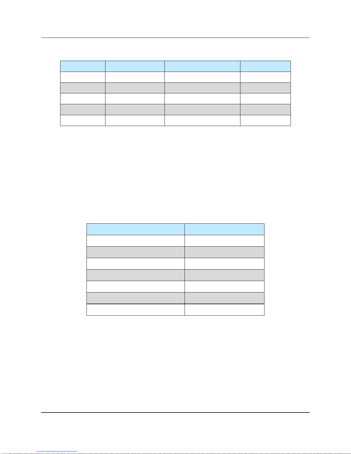
Table 1-1: Recommended Output Power Thresholds
for Waveguide System Pressurization
Satcom Band Frequency Range Amplifier Output Power Waveguide
S Band 1.7-2.6 GHz > 10 kW WR430
C-Band 5.7 - 6.7 GHz > 2 kW WR137
X-Band 7.9-8.4 GHz > 1kW WR112
Ku-Band 13.75-14.5 GHz > 500W WR75
Ka-Band 27-31 GHz > 100W WR28
It is a common misconception to look up the maximum theoretical power handling of a
particular type of waveguide and assume that this is the maximum power handling.
This may be the case for a straight waveguide tube with ideal terminations but these
values must be significantly de-rated in practical systems. Phase combined amplifier
systems can be particularly sensitive to the potential for waveguide arcing. This is due
to the numerous bends, magic tees, multiple waveguide flange joints, and other wave-
guide components. Table 1-2 shows the power handling capability of some popular
waveguide components normalized to the waveguide power rating. From this table, we
can see how a practical waveguide system’s power handling will de-rate significantly.
Table 1-2: Relative De-rating of Popular Waveguide
Components Relative to Straight Waveguide
Waveguide Component Relative Power Rating
H Plane Bend 0.6 to 0.9
E Plane Bend 0.97
90o Twist 0.8 to 0.9
Magic Tee 0.80
E-Plane Tee 0.06
H-Plane Tee 0.80
Cross Guide Coupler 0.21
Most waveguide systems have many of these components integrated before reaching
the antenna feed. It is not uncommon for a Satcom waveguide network to de-rate to
5% of the straight waveguide power rating.
The load VSWR also has an impact on the breakdown threshold in waveguide networks. Standing waves degrade the power handling of any transmission line network.
The graph of Figure 1-1 shows the rapid degradation of waveguide breakdown vs.
load VSWR. The chart shows that for a 2.0:1 load VSWR, the breakdown potential will
be half of what it would be with a perfectly matched load. This can degrade even more
when high Q elements such as band pass filters are included in the waveguide network.
16 205356 REV T 3 RU SSPA Chassis Operations Manual

DegradationofBreakdownPowerbyVSWR
1.00
0.90
0.80
0.70
0.60
0.50
0.40
0.30
0.20
PowerDegradation Ratio
0.10
0.00
1
1.1
1.2
1.3
1.4
1.5
1.6
1.7
1.8
1.9
2
2.1
2.2
2.3
2.4
2.5
2.6
2.7
2.8
2.9
3.0
Load VSWR
Figure 1-1: Degradation of Breakdown Power by VSWR
There are many factors to consider with high power amplifier systems in terms of the
output waveguide network. Especially when using HPA systems with output power
levels of Table 1-1, it is imperative to ensure that the output waveguide network is
pristinely clean and dry. An appropriate dehydrator should be used with capability of
achieving adequate pressure for the system’s output power. Take extra precaution to
make sure that any waveguide flange joints that are not already in place at the factory
are properly cleaned, gasket fitted, and aligned. A properly designed and maintained
waveguide network will ensure that no arcing can be supported and will provide many
years of amplifier service life.
3 RU SSPA Chassis Operations Manual 205356 REV T 17

THIS PAGE LEFT INTENTIONALLY BLANK
18 205356 REV T 3 RU SSPA Chassis Operations Manual
Section 2: Operation of Stand-Alone Unit
2.0 Introduction
This section contains operating information including a description of the front panel
indicators and controls, and I/O connectors and their functions.
2.1 Description of Controls, Indicators and Connectors
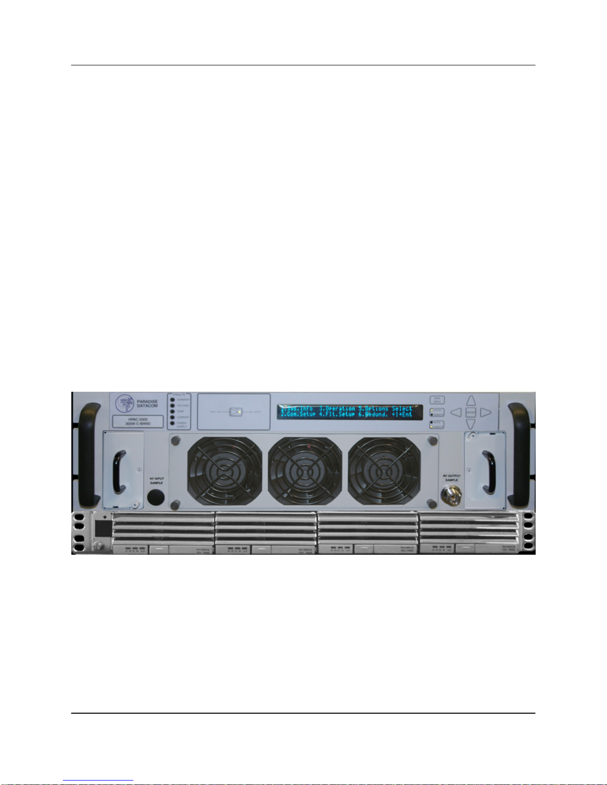
2.1.1 Front Panel Features
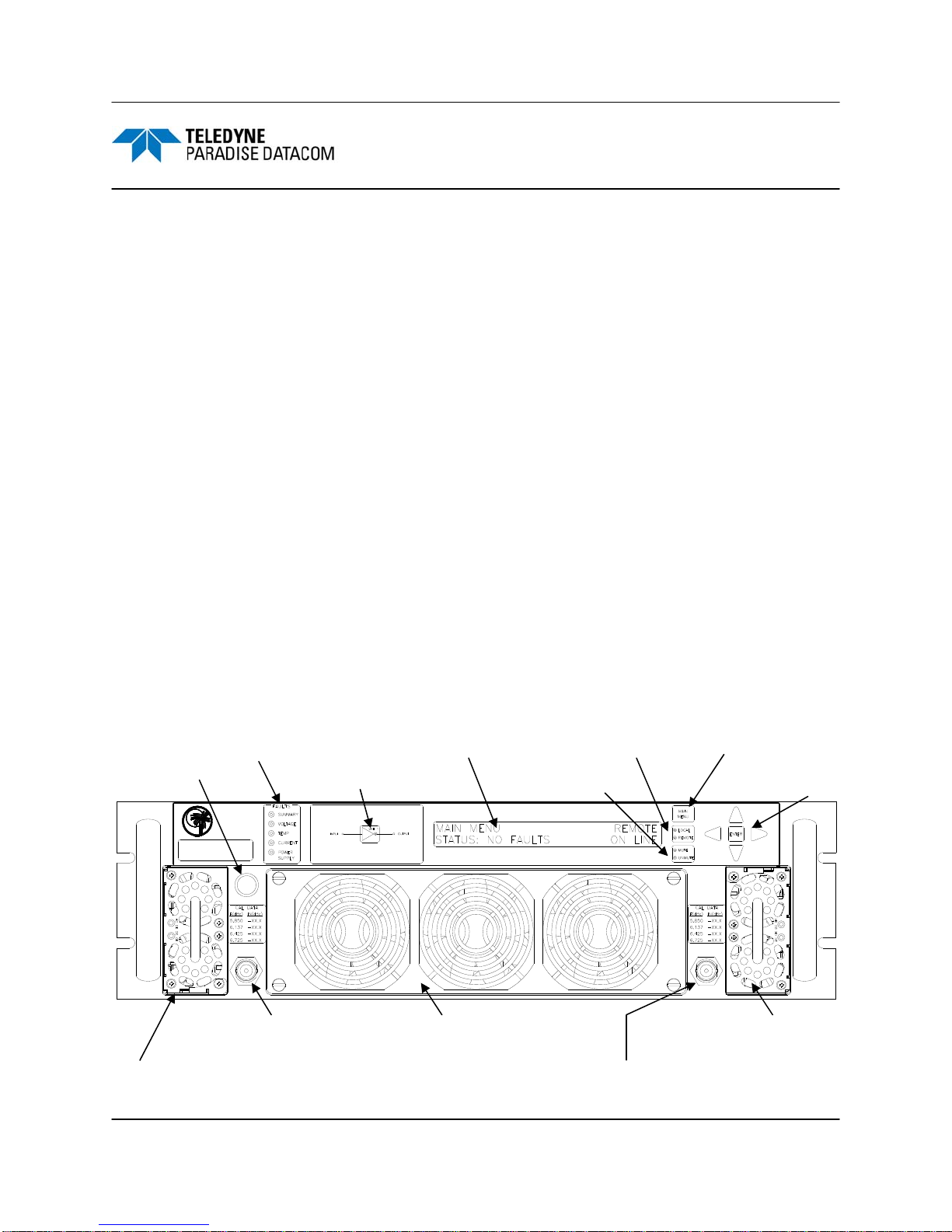
Figure 2-1 shows an illustration of the front panel view of a standard 3RU Rack Mount
chassis. The front panel features the prime power connection, a removable Monitor &
Control Card Assembly, removable fan assemblies, and the RF input and output ports.
2.1.1.1 Fault Condition LEDs
The RM SSPA has five fault condition LEDs on left side of the front panel which reflect
some of the HPA major faults plus the summary fault state.
2.1.1.2 Standby Select Key
The LED in this key illuminates when an HPA in a redundant system is Online, and
otherwise acts as a power ON indicator for a standalone HPA. Pressing this key will
put the Online HPA in a redundant system into Standby mode. Pressing this key has
no effect on a standalone HPA, and on the Standby HPA in a redundant system.
Fault Condition LEDs
Power Switch
(optional)
PARADISE
DATACOM
HPAC3-250
250W C-BAND
RF INPUT
RF INPUT
SAMPLE
SAMPLE
RF Input Sample Port (optional)
Removable Power Supply
40x2 Display Local/Remote key
Standby Select key
Mute/Unmute key
Removable Fan Assembly
RF Output Sample Port
Main Menu key
Navigation keys
RF OUTPUT
RF OUTPUT
SAMPLE
SAMPLE
Removable Power Supply
(in higher power units)
Figure 2-1: 3RU SSPA Chassis Front Panel
3 RU SSPA Chassis Operations Manual 205356 REV T 19

2.1.1.3 Front Panel Display
The front panel 40x2 character display allows the user to get detailed information
about state of the HPA and provides easy customization of operation through an
interactive menu structure.
2.1.1.4 Navigation Keys
The Up, Down, Left, Right and Enter keys on the right side of the front panel allow the
user to navigate through the menu selections displayed on the front panel display.
2.1.1.5 Main Menu Key
Provides a shortcut to the SSPA main menu.
2.1.1.6 Local/Remote Key
Allows the user to disable or enable the local control keypad console. If the SSPA is in
“Remote Only” mode, the unit will not react on any keystrokes except the “Local/
Remote” key.
2.1.1.7 Mute/Unmute Key
Provides an easy way to change the Mute state of the SSPA. Muting the amplifier via
the front panel requires 100 msec maximum (50 msec minimum). See Section
2.1.2.9.1 for a description of alternative muting methods.
2.1.1.8 Input Sample Port (Optional) [N-type (F)]
An optional RF input sample port is located on the lower left corner of the SSPA front
panel. This provides a -10 dBc coupled sample of the RF input signal. It is a N-type (f)
connector.
2.1.1.9 Output Sample Port (N-type (F))
The Output RF Sample Port connector is located on the right lower corner of the HPA
front Panel. This provides a -40 dBc coupled sample of the RF output signal. A
calibration sticker is located above the N-type (f) connector.
2.1.1.10 Removable Fan Assembly
The front panel fan assembly can be removed for maintenance. See Section 3. The
three-fan assembly operates at 20 VDC.
20 205356 REV T 3 RU SSPA Chassis Operations Manual
2.1.1.11 Removable Power Supply Modules
For units not using the external power supply, and depending on the power level of the
HPA, either one or two removable power supply modules are housed in the chassis.
Each module is a 1200W power supply, which has a single phase universal AC input
ranging from 90-265 VAC, 47-63 Hz and is power factor corrected to 0.99.
2.1.1.12 Front Panel Power Switch (Optional)
The 3RU SSPA Chassis has an optional front panel power switch which allows easy
access. This switch is illuminated when in the ‘on’ position.
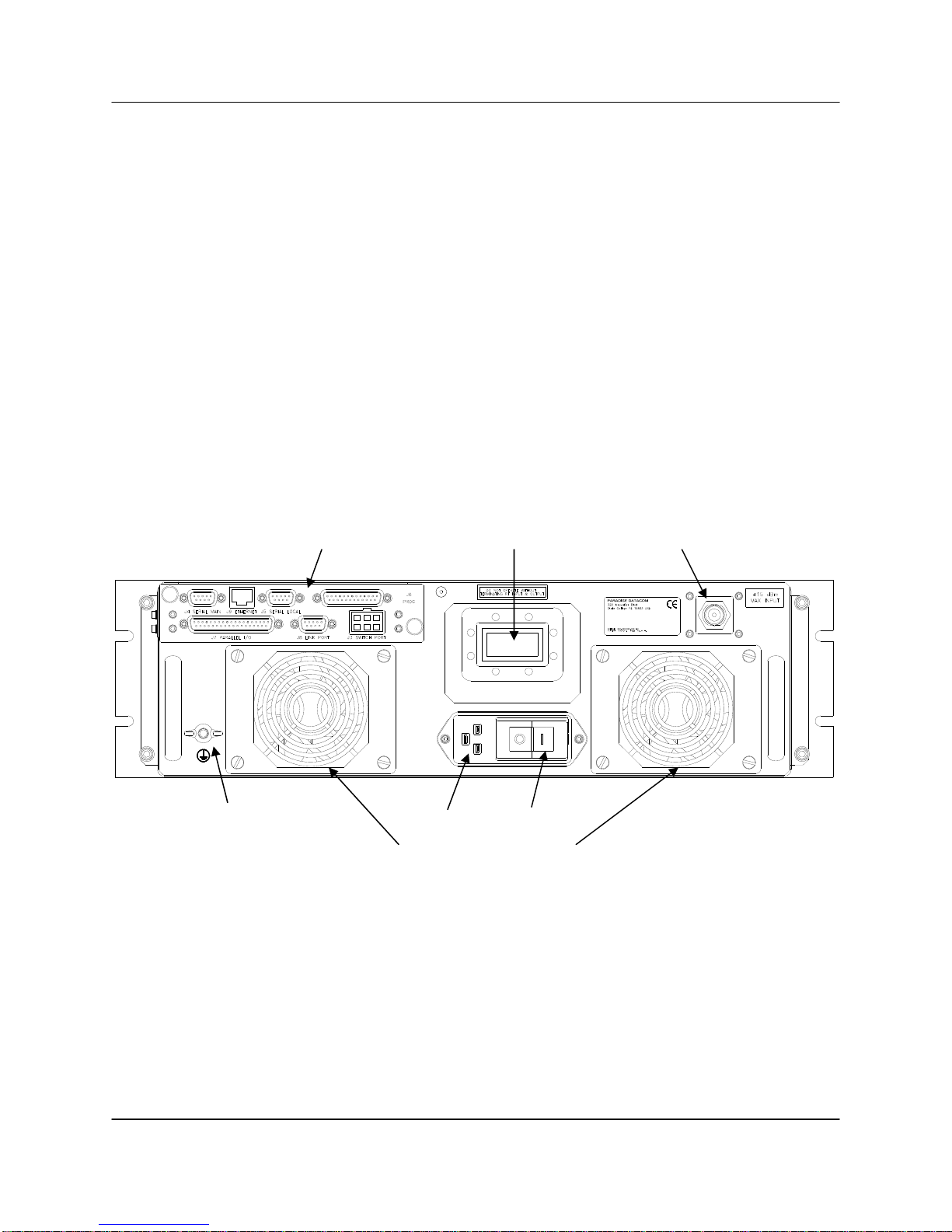
2.1.2 Rear Panel Features
Figure 2-2 shows an illustration of the rear panel view of a standard AC input Rack
Mount chassis. The rear panel features the prime power connection, a removable Monitor & Control Card Assembly, removable fan assemblies, and the RF input and output
ports.
M&C Card Assembly RF Output RF Input
J1
RF IN
AC IN
MODEL: XXXXXXXXXXXX
S/N: XXXX
RF OUT
J2
J10
P/N: LXXXXXX-X
Ground stud AC Input Power Toggle
Removable Fan Assemblies
Figure 2-2: C-Band SSPA Rear Panel
2.1.2.1 AC Input Port (J10) [IEC 6100-3300 (F)]
The prime power connector, J10, provides universal AC input by using auto-sensing
power supplies. The AC input can operate over a range of 90-265 VAC, at 47 to 63 Hz.
The power supply is also power factor corrected, enabling the unit to achieve a power
factor greater than 0.93. An IEC 6100-3300 (F) connector is used and a connecting
cable is included with the amplifier.
3 RU SSPA Chassis Operations Manual 205356 REV T 21
2.1.2.2 DC Input with N+1 Redundant External Power Supply (J10) (Option)
The combination of a separate +12 VDC output, fully redundant power supply is an
excellent means of obtaining the ultimate system reliability. The power supply is an
N+1 redundant configuration, meaning that a failure of a single power supply module
will not take the amplifier off the air.
In addition, the power supply modules are removable from the front panel while in
operation. There is never a need to remove the power supply from the equipment bay.
Weighing only 9 lbs. (4 kg) and occupying only 1 rack unit of cabinet space, the
redundant power supply chassis is an excellent companion to the SSPA chassis.
Power connection to the SSPA is via quick-snap connectors to the input power
bulkhead at Port J10.
Each power supply has a single phase, universal AC input ranging from 90-265 VAC,
47-63 Hz and is power factor corrected to 0.99. Depending on the power requirements
of the SSPA, the power supply is configured with up to four (4) 1200W hot-swappable
modules, each of which weigh approximately 5 lbs. (2.3 kg).
Figure 2-3 shows a 3RU SSPA chassis with a N+1 Redundant External Power Supply.
Note the blanking panels in place of the power supplies normally integral to the SSPA
chassis.
Figure 2-3: 3RU SSPA Chassis with 1RU N+1 Redundant Power Supply
It should be noted that if a power module is removed from the chassis during normal
operation, it will trigger a power supply fault. The operator must wait 30 seconds before
re-inserting the module or the fault will not clear.
The power supply chassis has a dual feed AC architecture. Power module slots 0 & 1
are supplied via AC Feed 1 and power module slots 2 & 3 are supplied via AC Feed 2.
22 205356 REV T 3 RU SSPA Chassis Operations Manual
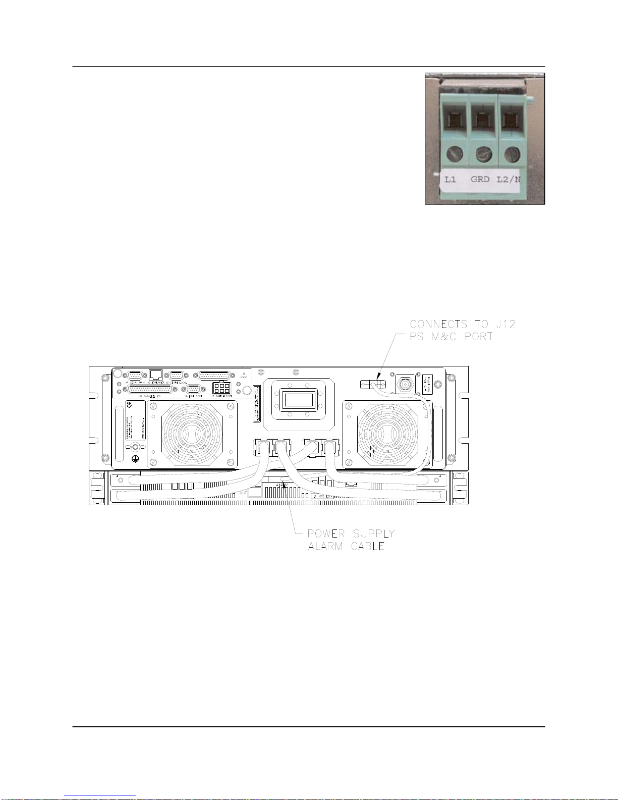
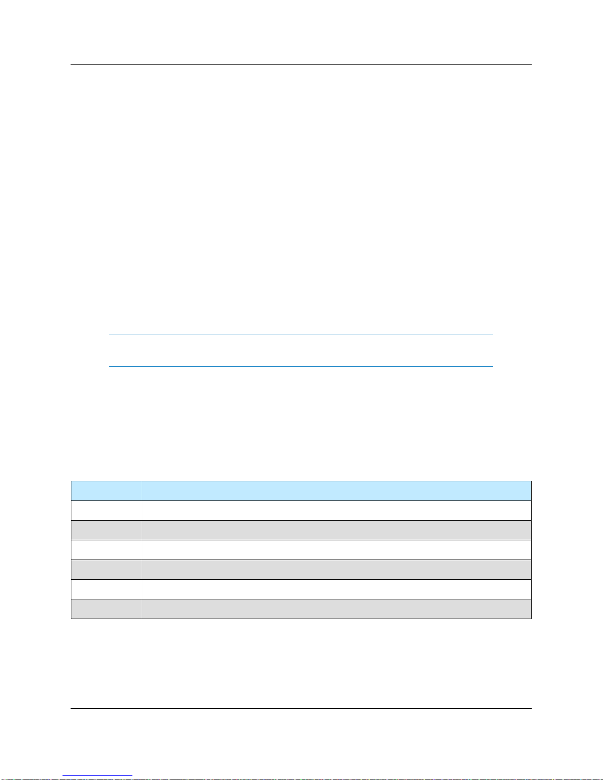
The AC connections on the shelf are made via rear accessed
compression style terminal blocks. See Figure 2-4. Connect
the first line/hot to L1, the second line or neutral to L2/N and
the AC ground to GND. These terminal blocks will accept up
to a maximum of 10 AWG wire, and should be torqued to
6 in-lbs.
The power supply is connected to the SSPA via an alarm
cable, part number L205676-1, supplied with the unit. This
cable connects between the Alarm port of the power supply
and the PS M&C Port (J12) of the SSPA. See Figure 2-5.
Figure 2-4:
Terminal block
Each power supply module has an alarm output. For logic reporting purposes, the
alarm outputs for power supply modules 1 and 2 are linked, as are those for power
supply modules 3 and 4. The power supply alarms are monitored by the SSPA Chassis
monitor and control system. This provides local and remote alarm reporting in the
event of a power supply module failure.
J12
PS M&C RF IN
RF OUT
J2
P/N: LXXXXXX-X
S/N: XXXX
MODEL: XXXXXXXXXXXX
+12VDC
IN
J1
Figure 2-5: Power Supply Alarm Cable Connection
The module alarms are open-collector signals with a high impedance state = fault logic
level. Under normal operation, the alarm outputs are in an open collector logic low
state.
The alarm connection from each power supply chassis is parallel connected by
supplied cable L206406-1. This cable also contains a current sharing line between the
two power supply chassis.
3 RU SSPA Chassis Operations Manual 205356 REV T 23
The power supply alarms may be monitored via the SSPA Chassis front panel menu.
See Section 2.2.1.2. In the event that one or more power supply modules enter a fault
condition, the SSPA Chassis will report a major (Summary) fault and will mute until the
fault conditions are cleared.
2.1.2.3 R3 Input Port (J1) [Type N (F)]
The type N female connector on the right side of the rear panel is used as the RF
input.
2.1.2.4 RF Output Port (J2) [Band specific]
L- and S-Band units have a coaxial output using a type N (f) connector. Higher frequency units utilize waveguide output flanges.
• C-Band: WR137 with a CPR-137 grooved flange;
• X-Band: WR112 with a CPRG112 grooved flange;
• Ku-Band: WR75 with a circular grooved flange.
Note: Do not operate the amplifier without having a termination or mating
connection on the RF Output Port. RF Hazard warnings apply.
2.1.2.5 Switch Port (J3) [6-pin MS-type]
A 6 pin Molex connector header with blind insertion system guides (mates with Molex
P/N 39-01-2060) is used in a 1:1 Redundancy System to provide switching for the
waveguide transfer switch (RF Switch). Table 2-1 shows the pin outs for the Switch
Port (J3).
Table 2-1: Switch Port (J3) Pin Outs
Pin # Function / Description
1 +28V Switch Drive Output. 3 Amp over current protection.
2 Switch 1 Position 2 drive
3 Switch 1 Position 1 drive
4 +28V Switch Drive Output. 3 Amp over current protection.
5 Switch 2 Position 2 drive
6 Switch 2 Position 1 drive
24 205356 REV T 3 RU SSPA Chassis Operations Manual
2.1.2.6 Serial Main (J4) [DB9 (F)]
A DB9 female connector serves as primary remote control interface connector. The
interface is re-configurable through the front panel or can be used as a RS-232 or
RS-485 interface (2 or 4 wires). The RS-485 TX and RX pairs must be twisted for maximum transmission distance. A user-configurable 120-ohm termination resistor is pro-
vided on the same connector. Table 2-2 shows the Serial Main (J4) connector pin outs.
Table 2-2: Serial Main (J4) Pin Outs
Pin # Function / Description
1 RS-485 TX+ (HPA Transmit +)
2 RS-485 TX- (HPA Transmit -)/RS-232 TX
3 RS-485 RX- (HPA Receive -)/RS-232 RX
4 RS-485 RX+ (HPA Receive +)
5 GND
6 Service Request 1 Form C relay NC contact (Closed on HPA Summary Fault)
7 Service Request Common Form C relay common contact
8 Service Request 2 Form C relay NO contact (Opened on HPA Summary Fault)
9 120 ohm termination (must be connected to pin 4 to enable termination)
2.1.2.7 Serial Local (J5) [DB9 (M)]
This DB9 male connector is used in advanced system integration and for system
debugging purposes. Leave unconnected unless specified otherwise.
2.1.2.8 Program Port (J6) [DB25 (M)]
A DB25 male connector is used to provide on field flash re-programmability for the
HPA controller card. In order to reload controller board firmware, connect this port to a
PC Parallel port through straight through cable. For a full description, see Section 3,
Troubleshooting and Maintenance.
2.1.2.9 Parallel I/O (J7) [DB37 (F)]
A DB37 female type connector, the Parallel I/O port contains a series of contact
closures for monitoring HPA faults as well as opto-isolated inputs for controlling some
HPA functions. Inputs react on the closure to ground. The minimal closure time is
50mS. See Table 2-3 for a description of the pin-outs for this connector.
3 RU SSPA Chassis Operations Manual 205356 REV T 25

Table 2-3: Parallel Connector (37 socket D connector) Pin Outs
Pin # Function / Description
1 Closed on Power Supply Fault Form C relay NC
2 Open on Power Supply Fault Form C relay NO
20 Power Supply Fault Common
21
22
3 Auxiliary Fault\Auto-Manual Common
4 Open on Mute. Form C Relay NC
5 Closed on Mute. Form C Relay NO
23 Mute Status Common
24 Closed on BUC Fault. Form C Relay NC
25 Open on BUC Fault. Form C Relay NO
6 BUC Fault Common
7 Closed on High Temperature Fault. Form C Relay NC
8 Open on High Temperature Fault. Form C Relay NO
26 High Temperature Fault Common
27
28
9 Regulator Low Voltage Fault\Standby-Online Common
10 Closed on DC Current Low Fault. Form C Relay NC
11 Open on DC Current Low Fault. Form C Relay NO
29 DC Current Low Fault Common
30 Closed on Low Forward RF Fault. Form C Relay NC
31 Open on Low Forward RF Form C Relay NO
12 Low Forward RF Fault Common
16 Auto/Manual toggle input. 50mS Closure to isolated ground to activate
17 Mute/Unmute toggle input. 50mS Closure to isolated ground to activate
18
35 HPA Standby input. 50mS Closure to isolated ground to activate
36 Local/Remote toggle. 50mS Closure to isolated ground to activate
37 Fault clear. 50mS Closure to isolated ground to activate
19 Isolated Signal Ground
15 +5V Isolated Power 20 mA
13, 32 +28V Auxiliary Power 1A
14, 33 Chassis Ground
1. Standalone mode. Closed on Auxiliary Fault
2. 1:1 Redundancy Mode. Closed on Automatic switchover mode. Form C relay NC
1. Standalone Mode. Open on Auxiliary Fault
2. 1:1 Redundancy Mode. Closed on Manual switchover mode. Form C relay NO
1. Standalone mode. Closed on Regulator Low Voltage Fault
2. 1:1 Redundancy Mode. Closed on HPA Standby. Form C relay NC
1. Standalone Mode. Open on Regulator Low Voltage Fault.
2. 1:1 Redundancy Mode. Closed on HPA Online Mode. Form C relay NO
Auxiliary Fault & Auxiliary Mute Input (See Section 2.1.2.9.1). 50 ms min. response
26 205356 REV T 3 RU SSPA Chassis Operations Manual
2.1.2.9.1 Hardware Mute (Tx Enable)
There are three ways to mute the amplifier via hardware input:
1. A 50 ms closure to ground on Port J7, Pin 17 toggles Mute/Unmute states;
2. Press the Main Menu key on the front panel; select 4.Fault Setup and press
the Enter key; select 2.Auxiliary Faults and press the Enter key; select
1.Action and press the Enter key; select 4.Alert+Mute and press the Enter
key; select 4.Fault Setup and press the Enter key; select 2.Auxiliary Faults
and press the Enter key; select 2.Fault Logic and press the Enter key; select 2.Fault on Low and press the Enter key. A continuous closure to
ground on Port J7, Pin 18 will then mute the amplifier. See Section 2.2.4.2;
3. Press the Main Menu key on the front panel; select 4.Fault Setup and press
the Enter key; select 2.Auxiliary Faults and press the Enter key; select
1.Action and press the Enter key; select 4.Alert+Mute and press the Enter
key; select 4.Fault Setup and press the Enter key; select 2.Auxiliary Faults
and press the Enter key; select 2.Fault Logic and press the Enter key; select 2.Fault on High. A continuous open to ground on Port J7, Pin 18 will
mute the amplifier. See Section 2.2.4.2.
2.1.2.10 Link Port (J8) [DB9 (M)]
The 9-pin male connector J8 Link Port is used to link a SSPA with other units in a
redundant system in order to pass online/standby status information between them.
Leave unconnected unless specified otherwise. See Section 4.1.4 and Section 5.5.
2.1.2.11 Ethernet Port (J9) [RJ45]
This is a RJ45 connector with integrated magnetics and LEDs. This port becomes the
primary remote control interface when the Interface is selected to “IPNet” as described
in Section 7.8. This feature allows the user to connect the unit to a 10/100 Base-T network and have full-featured M&C functions through a web interface. See Table 2-4.
Table 2-4: Ethernet Port (J9) Pin Outs
Note: IP address, Gateway address, Subnet mask, IP port and IP Lock
address need to be properly selected prior to first use (see Appendix A).
LED lamps on the connector indicate network status. A steady Green light indicates a
valid Ethernet link; a flashing Yellow LED indicates data transfer activity (on either the
Transmit and Receive paths).
3 RU SSPA Chassis Operations Manual 205356 REV T 27
Pin # Function / Description
1 TX+
2 TX-
3 RX+
6 RX-
4,5,7,8 GND
2.1.2.12 Removable Fan Assembly
The rear panel fan assemblies can be removed for maintenance or replacement. See
Section 3, Troubleshooting and Maintenance, for more details. Each of the two rear
fans operate at 24 VDC.
2.2 Menus
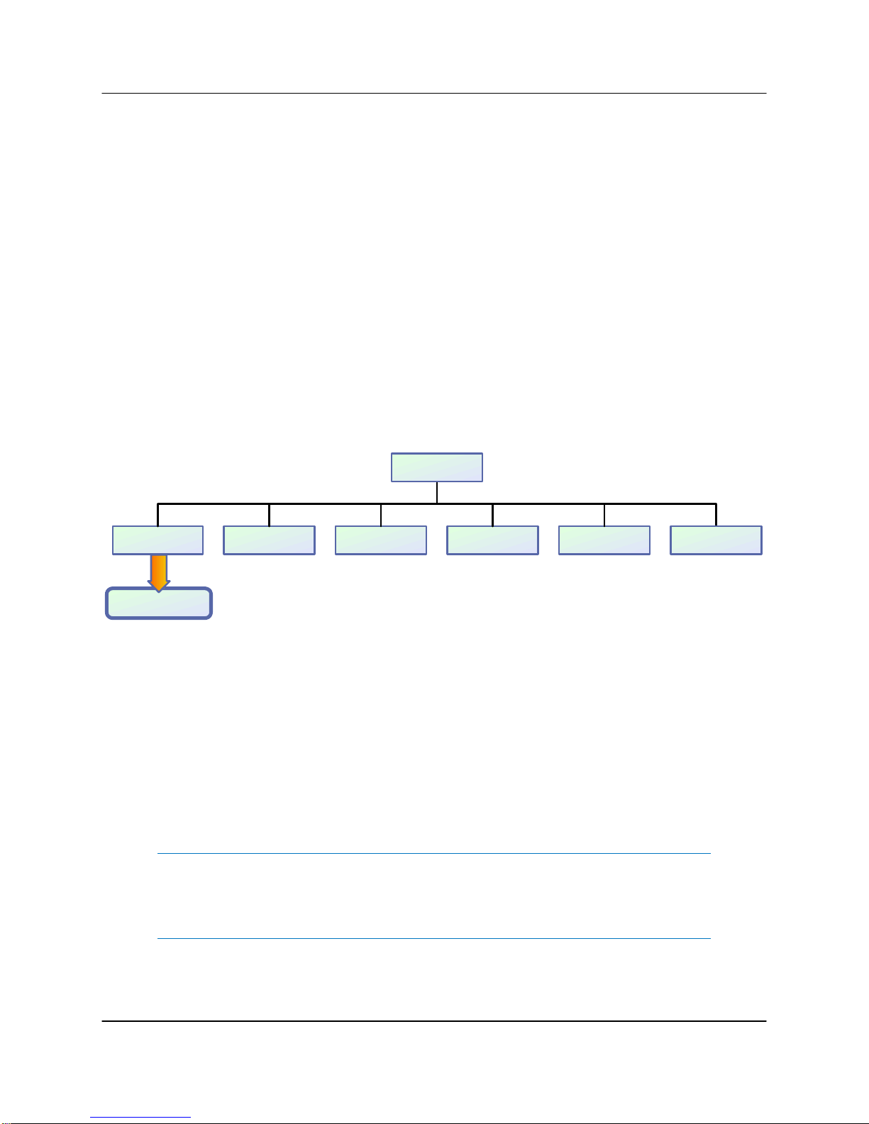
Figure 2-6 shows the Front Panel Menu Structure hierarchy. There are six main levels
of menu selections.
1. Sys.Info - System Information menu sublevel (See Section 2.2.1)
2. Com.Setup - Serial Communication related settings (See Section 2.2.2)
3. Operation Setup - System operation related settings (See Section 2.2.3)
4. Fault Monitoring Setup - Fault handling settings (See Section 2.2.4)
5. Options - Backup/restore and password settings (See Section 2.2.5)
6. Redundancy - Switching and standby settings (See Section 2.2.6)
Main Menu
2.Com Setup1.Sys Info 3.Operation 4.F l t. Se tu p 5.Options
To Sys Info Page 1
6.Redundancy
Figure 2-6: Front Panel Menu Structure
The menu tree is accessed by pressing the Main Menu key on the front panel of the
SSPA. Navigation through the menu structure is handled by using the Up Arrow [▲],
Down Arrow [▼], Left Arrow [◄], and Right Arrow [►] keys and the Enter key to
select from the items shown in the front panel display.
For menus where an actual numerical value must be entered, the Up Arrow [▲] and
Down Arrow [▼] keys change the number by factors of 10; the Left Arrow [◄] and
Right Arrow [►] keys change the number in increments of 1.
Note: If the Local/Remote key is toggled so that the Remote LED is
illuminated, the Main Menu key, Arrow keys and Enter key are disabled.
To regain local control, press the Local/Remote key so that the Local
LED is illuminated.
28 205356 REV T 3 RU SSPA Chassis Operations Manual
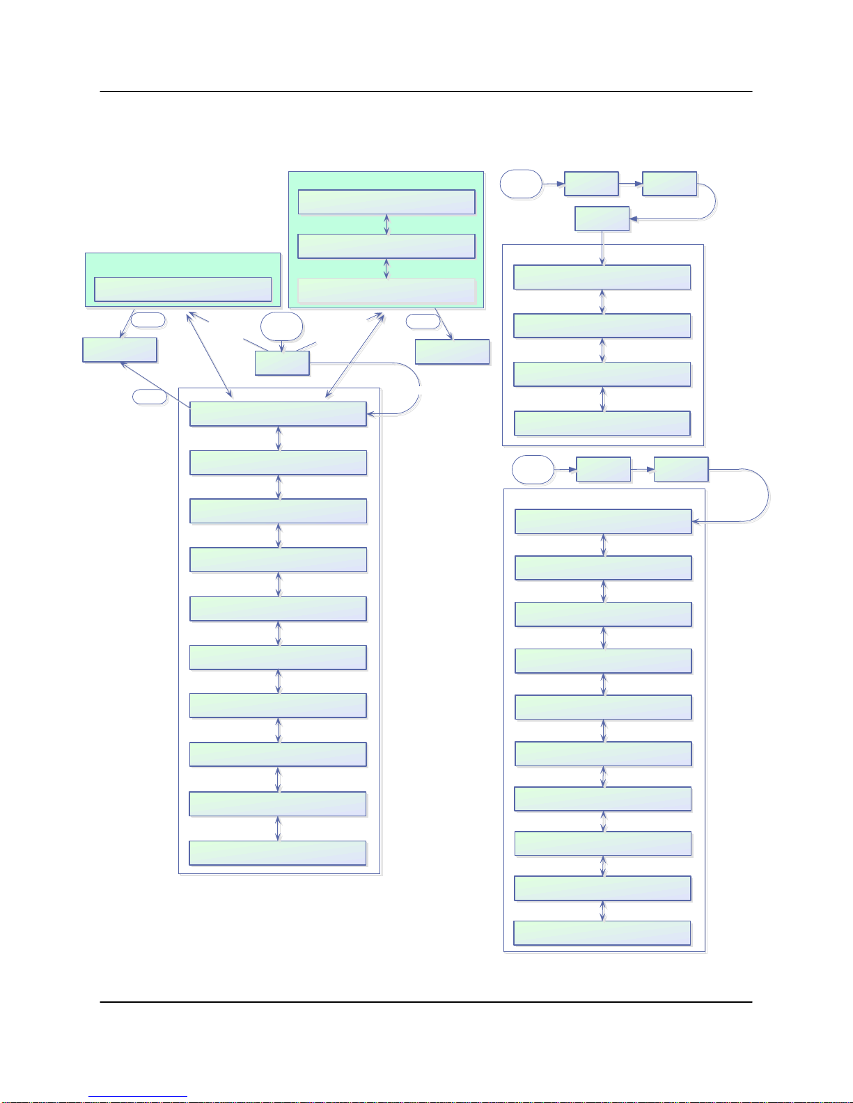
2.2.1 System Information Sub-Menu
The informative sublevel menu structure contains several pages, shown in Figure 2-7.
Unit operation under system c ontr ol
Enter
1.Clear Faults
2.Back
Enter
N+1 Slave unit system info
N+1 Slave Unit
S
l
a
v
e
U
System Info Menus
Atten.(dB):XX.X FrwrdRF(dBm):XX.X
Alarms:XXXXXX Ref.RF(dBm):XX.X
PS:XXXXXX LowRF:XXXXXX Fan:XXXXXX
AU X:XXXXXX VSWR:XXXXXX BUC: XXXXXX
RFSW1:XXXXXX State:XXXXXX Prior:XXXX
RFSW2:XXXXXX Mute:XXXXXX PolSel:XXXX
Prtcl:XXXXXX Intrfc :XXXXX Buzzer:XXX
Baud:XXXXX Addrs.:XXX Latch:XXX
Main
Menu
n
i
t
s
1.Sys.Info
N+1 Master unit system info
Cabinet Temp(C):XXX N+1Stbys ::XXXXXX
Cabinet Fan:XXXXXX
N+1 Arr.Size:XXX N+1 Alarms:XXXXXX
N+1 Address :XXX N+1 State:XXXXXX
Atten.(dB):XX.X SysRFOut(dBm):XX.X
AutoGain(dB):XX.X Ref.RF(dBm):XX.X
y
l
n
o
t
i
n
U
r
e
t
s
a
M
Enter
1.Clear Faults
2.Back
Non N+ 1 Un its
Main
Menu
IPAddr:XXX.XXX.XXX.XXX MAC:XXXXXXXXXX
CommunityGet:XXXXXXXXXXXXXXXXXXXXX
CommunitySet:XXXXXXXXXXXXXXXXXXXXX
Web Password:XXXXXXXXXXXXXXXXXXXXX
TrapNM SIP: XXX.XXX.XXX.XXX
Main
Menu
Digicore X Version X.XX (XX) Built YYYY.MM.DD
2.Com Setup 5.IPSetup
1.IPInfo
IP Setup Menus
Subnet:XXX.XXX.XXX.XXX Port:XXXXX
Gateway:XXX.XXX.XXX.XXX
LockIP:XXX.XXX.XXX.XXX
3.Operation
SSPA Firmw are Info
Teledyne Paradise Datacom LLC
SSPAID:XXXXXXXXXXXXXXXXXXXX
UserInfo:XXXXXXXXXXXXXXXXXXXX
1.Info
Mode:XXXXXXX Ctrl:XXXXXX Unit:XXXX
Stby:XXXX Switch:XXXXX FSpeed:XXX
PS1(V):XX.X Boost1( V):XX.X DC(A):XX.X
PS2(V):XX.X Boost2(V):XX.X
Regulator:XXXXXX Temperatu r e:XXXXXX
DCCurrent:XXXXXX Temp . ( C) :XXX
Mod1:XXXXX Mod3:XXXXX PreAmp:XXXXX
Mod2:XXXXX Mod4:XXXXX PSModFlts:XXX
Chssy T em p( C) :XXX BUCPS1(V): XX.X
RecordHigh(C):XXX BUC PS2(V):XX.X
MuteFault:XXXXX LastFault:XXXXX
MFaultCause:XXXXX MasterN1IP:XXX
Figure 2-7: System Information Menu Structure
Firmware:XXXXXXXXXX M odul e 1
ID:XXXXXXXXXXXXXXXXXXXXXX
Firmware:XXXXXXXXXX Module2
ID:XXXXXXXXXXXXXXXXXXXXXX
Firmware:XXXXXXXXXX Module3
ID:XXXXXXXXXXXXXXXXXXXXXX
Firmware:XXXXXXXXXX Module4
ID:XXXXXXXXXXXXXXXXXXXXXX
Firmware:XXXXXXXXXX PreAmp
ID:XXXXXXXXXXXXXXXXXXXXXX
PSType:XXX DigicoreID:XXX
I/OBoardID:XXX
Current Date/Time:
YY/MM/DD HH :MM:SS
HPA R u n T im e :
Days:DDDD Hrs:HH Min:MM Sec:SS
3 RU SSPA Chassis Operations Manual 205356 REV T 29

The user can also browse among these pages by navigating the cursor around the
menu fields and pressing the Enter button on the keypad. Note that this function will
not work if the “Fault Latch” option is selected.
In a N+1 configuration, the Master unit default System Information page is as de-
scribed in Section 2.2.1.21; the default page for Slave units is as described in Section
2.2.1.22. In non-N+1 configurations, the default page is as described in Section
2.2.1.1.
2.2.1.1 Sys Info Page 1
This is the HPA main status information page. The page shows:
• Atten.(dB) — HPA attenuation measured in dB, with accuracy of 0.1 dB;
• FrwrdRF(###) — Forward RF Power, measured in either dBm with reso-
lution of 0.1 dBm, or Watts with a resolution of 0.1 Watts, with a 20 dBm
dynamic range from the maximum rated output power;
• Alarms — Will display “FAULT!” if a fault is present on the HPA, or
“None” if no fault is present.
• Ref.RF(###) — Reflected RF Power, measured in either dB with resolu-
tion of 0.1 dBm, or Watts with a resolution of 0.1 Watts. Displays “N/A” if
unavailable. See Section 2.5 for further discussion.
When on this page, pressing the Enter key will open the Clear Faults Menu. The Clear
Faults Menu is also available from the N+1 Master Page 1 and N+1 Slave Info Page.
2.2.1.1.1 Clear Faults Menu
This page allows user to clear latched faults conditions, if the Fault Latch option is enabled.
• 1.Clear Faults — When selected, all latched fault conditions are cleared.
Also Master N+1 unit fault history and SNMP trap history will be cleared
when “Clear Faults” function is selected.
• 2.Back — When selected, navigates back to System Info page without
clearing fault state holders.
30 205356 REV T 3 RU SSPA Chassis Operations Manual

2.2.1.2 Sys Info Page 2
This page shows a variety of alarm states which may be present within the HPA. Fault
values could be “FAULT!”, “Normal” and “N/A”. If the fault condition doesn't apply to the
HPA it will display “N/A” for “Not Available”.
• PS — Power supply alarm, displays “Normal” if HPA power supplies are
normally operational and “FAULT!” if one or more power supplies failed.
• LowRF — Low RF fault;
• Fan — Cooling system failures;
• Aux. — Auxiliary fault condition;
• VSWR — High Reflected power fault;
• BUC — Block Up converter fault.
2.2.1.3 Sys Info Page 3
This page displays miscellaneous information related to the redundancy operation and
the HPA mute status.
• RFSW1 — Displays the state of RF switch 1, possible values - “Pos1”,
“Pos2”, “N/A”, “FAULT!”;
• RFSW2 — Displays the state of RF switch 2, possible values - “Pos1”,
“Pos2”, “N/A”, “FAULT!”;
• State — HPA online state, possible values “Online”, “Standby”;
• Mute — HPA mute state, possible values “Clear”, “Set”;
• Prior — Priority polarization select (1:2 Mode Only);
• PolSel — Current Polarization output (1:2 Mode Only)
2.2.1.4 Sys Info Page 4
This page displays various HPA settings:
• Prtcl. — Current HPA remote control protocol. Will display “Terminal”, if
terminal mode protocol is currently active and “Normal” if string I/O type
protocol is used.
• Baud — Selected baud rate for remote control serial port. Selection:
“2400”, “4800”, “9600”, “19200”, “38400”;
• Intrfc. — Selected serial port interface. Selection: “RS232”, “RS485”.
• Addrs. — HPA remote control network address. Value could be in range
from 0 to 254. Note: address 255 is reserved for global calls and should
not be used for an individual unit’s addressing.
• Buzzer — Audible alarm availability. “Dis” for disabled; “Enb” for enabled.
• Latch — Fault latch option selection. “Dis” for disabled; “Enb” for ena-
bled.
3 RU SSPA Chassis Operations Manual 205356 REV T 31

2.2.1.5 Sys Info Page 5
Page 5 shows settings related to the HPA 1:1 Redundant System operation.
• Mode — Indicates HPA operational mode. See Section 2.2.3.4.
• Stby. — Shows the HPA standby state selection. “Hot” - Hot standby op-
eration (HPA retains unmuted state during standby); “Cold” - Cold
standby (HPA always mutes itself in standby mode and unmutes when
switched online).
• Ctrl. — Shows HPA control style. “Local” - Both local and remote control
are supported; “Remote” - When only remote control provided (keypad
locked);
• Switch — Indicates switching style. “Auto” - Automatic fault tracking/
switching; “Manual” - If redundancy switching is provided by the operator.
• Unit — Redundancy topological factor. “HPA1” - HPA connected to RF
switch port 1 or 4 (Online Position 1 of the RF switch); “HPA2” - HPA
connected to RF switch port 2 or 3 (Online Position 2 of the RF switch).
• FSpeed — Displays the current fan speed setting of “Hi”, “Low” or “Auto”.
2.2.1.6 Sys Info Page 6
This page shows the status of the HPA’s internal power supplies.
• PS1(V) — Main power supply 1 output voltage with resolution of 0.1V.
Normal output voltage for GaAs amplifiers is in the range of 11 to 13 V;
The voltage range for GaN amplifiers depends on the frequency band of
the unit. Typical GaN SSPA power supply ranges are:
○ L– and S-Band SSPAs: 40 to 50 VDC;
○ C-Band SSPAs: 24 to 28 VDC;
○ X-Band SSPAs: 20 to 26 VDC;
○ Ku-Band SSPAs: 20 to 28 VDC;
○ Ka-Band SSPAs: 20 to 24 VDC.
• PS2(V) — Main power supply 2 output voltage. See above.
• Boost1(V) — Booster power supply 1 output voltage with resolution of
0.1V. Normal range 24 to 30 V (typical 28V);
• Boost2(V) — Booster power supply 2 output voltage.
• DC (A) — Total DC current draw by RF modules from main power sup-
ply. Value varies depending on the power level of the HPA. If the HPA is
muted, current normally drops to within the 0 to 5 A range.
32 205356 REV T 3 RU SSPA Chassis Operations Manual

2.2.1.7 Sys Info Page 7
This page shows RF module related faults and conditions.
• Regulator — RF module regulator low voltage fault. Values: “FAULT!” or
“Normal”;
• DC Current — Low DC current fault. Values: “FAULT!” or “Normal”;
• Temperature — High temperature fault. Values: “FAULT!” or “Normal”.
• Temp.(C) — Internal RF module plate temperature in Celsius. In multi-
module units, only the hottest module baseplate temperature is displayed.
2.2.1.8 Sys Info Page 8
This page shows individual RF module states in multi-module HPAs.
• Mod# & PreAmp — Mod1 to Mod4 represent the overall state of the rele-
vant RF Power modules. If the amplifier is equipped with a separate preamplifier module, the “PreAmp” value will represent the overall state of
the pre-amplifier. Under normal operation, the value will read “Normal”.
If a unique module does not exist in the HPA configuration, the value
shows “N/A” (not available). Each value represents the summary fault
state of an individual RF module, which includes the Voltage, Current and
Temperature state as well as the quality of data connection with module.
For a module or pre-amp exhibiting a fault condition, the value will read
“FAULT!”.
If the HPA controller card cannot reliably communicate with an SSPA
module, that module will be declared faulted. This type of fault will not affect the overall summary fault state, because the controller card has the
ability to track RF module faults independently. When an existing module
or pre-amp is present in the current HPA configuration, but fails to respond to control board status queries, “ComErr” (Communication Error)
will be displayed.
• PSModFlts — For amplifiers utilizing an external N+1 power supply, this
value indicates the number of detected N+1 PS module faults. For units
with an internal power supply, this value reads “000” and should be ignored. Check PS1 and PS2 Voltage readings to assess the state of an
internal power supply.
3 RU SSPA Chassis Operations Manual 205356 REV T 33

2.2.1.9 Sys Info Page 9 (version 6.00)
This page shows various miscellaneous operation parameters.
• Chssy Temp — Chassis temperature reading measured by the control
board. Since the control board is typically located at rear of the chassis,
this reading correlates with the exhaust air temperature;
• RecordHigh — The highest temperature detected over unit lifetime. This
value is updated each time a temperature higher than the current record
is detected. Value could be used for SSPAs problem troubleshooting.
Record data is factory reset only.
• BUC PS1(V) — This value represents the power supply voltage used for
biasing an optional BUC unit. Voltage could be used for detecting problems related to BUC operation. The SSPA does not have a specific alarm
threshold for this voltage. Normal reading for this parameter should be in
range of 15V– 16V.
• BUC PS2(V) — This value represents secondary BUC power supply volt-
ages. For a unit equipped with a single power supply this value shows “N/
A” (not available).
2.2.1.10 Sys Info Page 10 (version 6.00)
The page shows advanced fault analysis information and advanced N+1 operation features.
• MuteFault – This parameter allows the user to check the SSPA mute
condition. Possible values:
○ Clear — No present fault mute condition on SSPA unit. Mute/Unmute
function under full user control;
○ Set — One or more mute fault conditions present in the system. The
unit is forced to the Mute On condition.
• MFltCause — Parameter allows user to determine last detected Mute
fault condition. Possible values:
○ None — No detected Mute fault conditions;
○ AuxFlt — Mute fault condition triggered by a detected Auxiliary fault.
○ ExtM — Mute condition forced by external signal applied on the par-
allel port Mute input;
○ BUCFlt — Mute fault condition caused by a detected BUC fault;
○ PSFlt — The unit is forced to mute due to one or more failed N+1
power supply modules;
○ N+1Flt — N+1 configuration forced unit into a mute state due to an
internal summary fault condition;
• LastFault – This parameter shows information about the last detected
fault. The value is latched to the last fault occurrence. Use the Clear Fault
function to reset. Possible Values:
34 205356 REV T 3 RU SSPA Chassis Operations Manual

○ LowRF – Low RF level fault;
○ AuxFlt – Auxiliary fault;
○ BUCFlt – Block Up converter fault;
○ PSFlt- Power Supply fault;
○ ColdSt – Unit cold start power up detected;
○ N+1Flt – N+1 System Fault;
○ TmpFlt – High temperature fault;
○ RegFlt – Voltage Regulator fault;
○ CurFlt – Low DC Current fault;
○ HiVSWR – High reflected RF level fault;
○ Other – Unknown fault condition;
○ None – No information about present or past fault conditions (Clear
Fault function was implemented by user);
2.2.1.11 IP Info Page 1
This page is available through the Comm. Setup menu, and shows SSPA settings related to the IP interface.
• IP Address – IP address of the SSPA. Consult your network administra-
tor to set this address according to your LAN configuration.
• MAC – Medium Access Control address of the SSPA Ethernet controller.
This address is factory preset.
• Subnet – IP subnet mask of the SSPA. Consult your network administra-
tor to set this address.
• IPPort – IP port value for the SSPA. This address is valid only when IP-
Net protocol is selected. The port value should not be selected outside
the existing services range to avoid access conflict on the M&C PC end.
2.2.1.12 IP Info Page 2
This page shows SSPA settings related to the IP interface.
• Gateway – IP Gateway address. This address is used only if access to
the SSPA is provided from an outside LAN. If no such access is required,
the address must be set to 0.0.0.0
• LockIP – This address is used to increase the security measure for the
IPNet protocol. The SSPA will answer a request which comes only from a
specified IP address. Set this address value to 255.255.255.255 to disa-
ble this feature. See Section 2.2.2.5.1.
3 RU SSPA Chassis Operations Manual 205356 REV T 35

2.2.1.13 IP Info Page 3
This page shows SSPA settings related to the IP interface.
• CommunityGet – Security string used in SNMP protocol for “Get” re-
quests. Set this value to match the value specified in the NMS or MIB
browser. Maximum string length is 20 alpha-numeric characters. The
string allows read operation for the RM SSPA SNMP agent.
• CommunitySet – Security string used in SNMP protocol for “Set” re-
quests. Set this value to match the value specified in the NMS or MIB
browser. For security reasons this string must be different than the Community Get string. The maximum string length is 20 alpha-numeric characters. The string allows write operation for the RM SSPA SNMP agent.
Note: Community strings are essentially passwords. The user should use
the same rules for selecting them as for any other passwords: no
dictionary words, spouse names, etc. An alphanumeric string with mixed
upper- and lower-case letters is generally a good idea.
2.2.1.14 IP Info Page 4
This page contains information about the web password and Trap NMSIP.
• WebPassword — Indicates the selected password for the web page in-
terface. A blank value indicates that the web interface does not require a
password protected login.
• TrapNMSIP — Shows the selected IP address for the SNMP trap recipi-
ent. (Version 6.00).
2.2.1.15 Firmware Info Page 1
This page is available through the Operation Setup menu, and provides information
about the SSPA micro-controller unit firmware revision level and build date.
2.2.1.16 Firmware Info Page 2 (version 4.0)
This page provides additional SSPA information.
• SSPA ID – SSPA unique serial and model number.
• UserInfo – User information string, which could be set over SNMP proto-
col (see SNMP MIB info for details)
36 205356 REV T 3 RU SSPA Chassis Operations Manual

2.2.1.17 Firmware Info Pages 3, 4, 5, 6 and 7 (version 4.0)
These pages contain information about the firmware revision level and unique ID of
each RF module. A unit may contain one to four RF modules and up to one preamplifier. Pages will remain blank if a particular module is not installed.
2.2.1.18 Hardware Info Page 8 (version 6.00)
This page shows the hardware ID markers for the power supply configuration, the type
of hardware build of the DigitalCore board and the I/O board. This information is for
factory use only.
2.2.1.19 HPA Local Time Page 9 (version 6.00)
This page shows the optional device clock. The device clock is a user selectable parameter. User set time is power dependent. A backup capacitor is used to keep the
clock running while the SSPA is powered down. The clock will need to be reset if the
unit remains without power longer than 5 hours.
Clock output format is Year/Month/Day Hours:Minutes:Seconds. Only 24-Hour format
is supported at this time.
2.2.1.20 HPA Run Time Page 10 (version 6.00)
This page shows the days, hours, minutes and seconds since the unit was last powered up.
2.2.1.21 N+1 Master Info Page 1
This page can only be viewed when the SSPA unit is configured as the N+1 Master
unit. The page also becomes the default startup page for the Master SSPA .
Several parameters related to N+1 System operational parameters are displayed:
• Atten.(dB) — System level attenuation. In the case when the N+1 Auto
Gain option is turned on, this attenuation level may differ from an individual SSPA attenuation level;
• AutoGain(dB) or SSPAGain(dB) — Displays the estimated system wide
linear gain. Actual SSPA gain may differ if the unit has reached its satu-
rated power level or malfunctions (see Section 2.2.6.6.3);
• SysRFOut — Indicates system forward RF output power detected at the
output flange of the final phase combined structure. This value can be
displayed in dBm or Watts, depending on the RF Unit setting. If the RF
power detector unit is not accessible for any reason, the value shown will
be “N/A”.
3 RU SSPA Chassis Operations Manual 205356 REV T 37

Note: If detected power falls below lowest detectable threshold it will read
0.00. In reality, RF output power may differ from the displayed value.
Consult the system datasheet on RF detector dynamic range
specifications.
• Ref.RF — Indicates system reflected RF power. This value can be dis-
played in dBm or Watts, depending on the RF Unit setting. If the RF power detector unit is not accessible for any reason, the value shown will be
“N/A”.
Note: If reflected power falls below lowest detectable threshold it will read
0.00. In reality, RF output power may differ from the displayed value.
Consult the system datasheet on RF detector dynamic range
specifications.
When on this page, pressing the Enter key twice will open the Clear Faults Menu. The
Clear Faults Menu is also available from Sys Info Page 1 and N+1 Slave Info Page.
2.2.1.21.1 Clear Faults Menu
This page allows user to clear latched faults conditions, if the Fault Latch option is enabled.
• 1.Clear Faults — When selected, all latched fault conditions are cleared.
Also Master N+1 unit fault history and SNMP trap history will be cleared
when “Clear Faults” function is selected.
• 2.Back — When selected, navigates back to System Info page without
clearing fault state holders.
2.2.1.22 N+1 Slave Info Page
Figure 2-8 shows the display for all Slave units in the system.
This page can only be viewed when a SSPA unit is assigned as a N+1 Slave unit. All
normal Info pages pertaining to individual SSPA operation parameters are accessible
on subsequent menu levels. This page becomes the default page for N+1 slave unit.
When on this page, pressing the Enter key will open the Clear Faults Menu. The Clear
Faults Menu is also available from Sys Info Page 1 and N+1 Master Page 1.
38 205356 REV T 3 RU SSPA Chassis Operations Manual
Figure 2-8: Slave Unit Display

2.2.1.22.1 Clear Faults Menu
This page allows user to clear latched faults conditions, if the Fault Latch option is enabled.
• 1.Clear Faults — When selected, all latched fault conditions are cleared.
Also Master N+1 unit fault history and SNMP trap history will be cleared
when “Clear Faults” function is selected.
• 2.Back — When selected, navigates back to System Info page without
clearing fault state holders.
2.2.1.23 N+1 Master Info Page 2
This page displays additional N+1 system operation data, and can be accessed by
pressing the Up Arrow (▲) key from the N+1 Master Info Page 1. This page is only
accessible from the N+1 Master unit.
• N+1 Arr.Size — Displays the N+1 array size. Valid sizes: 2, 4, 8 or 16
units.
• N+1 Address — Displays the master unit N+1 priority address;
• N+1 Alarms — Displays the number of detected SSPA unit alarms pre-
sent in the system.
• N+1 State — Displays the current N+1 fault state. If the Master unit de-
tects no more than one (1) SSPA chassis alarm, the N+1 state will be
displayed as “Normal”; otherwise “FAULT!”.
2.2.1.24 N+1 Master Info Page 3
This page displays information related to N+1 system operation, and can be accessed
by pressing the Up Arrow (▲) key twice from the N+1 Master Info Page 1. This page
is only accessible from the N+1 Master unit.
• Cabinet Temp(C) — Displays the temperature within the system cabinet.
• Cabinet Fan — Displays the fault state of the cabinet exhaust impellers.
Possible states are: “Normal”, “FAULT!” or “N/A”.
3 RU SSPA Chassis Operations Manual 205356 REV T 39

Mai n Menu
To IP Info Page
1.2400
1.Sys Info
1.Normal
2.4800
1.IPInfo
1.Community Get
1.SetTrap
2.Com Setup
1.Protocol
2.Terminal
1.RS232
2.LocalIP
2.Community Set
2.CondTrap
3.9600
3.Operation
2.Baud Rate
2.RS485
3.SysAddress
4.19200
3.Subnet
3.Lock IP
3.TimeSet 4.TrapNMSIP
1 .. 255
5.38400
3.IPNet
4.Gateway
4.Web Password
4.Fl t. Se tu p
4.Interface
4.SNMP
5.Options
5.IP Setup
5.LocalPort
5.More 6.Back
5.Back
6.Redundancy
6.N+1Cntrl
6.More
3.SerAddrs2.MasterIP Dis 4.IPAddrs 5.Info 6.Back1.MasterIP Enb
Figure 2-9: Communication Setup Sub-Menu
2.2.2 Communication Setup Sub-Menu
This menu, shown in Figure 2-9, allows the user to select the parameters for commu-
nication between the SSPA and any remote monitor and control station.
2.2.2.1 Protocol
Allows the user to select the serial protocol. Available communication protocols include:
• 1.Normal — As described in Section 8.
• 2.Terminal — As described in Section 8.5.
2.2.2.2 Baud Rate
Selects the desired baud rate for serial communication. Available baud rates include
2400, 4800, 9600, 19200 and 38400. The factory default Baud Rate is 9600.
40 205356 REV T 3 RU SSPA Chassis Operations Manual

2.2.2.3 System Address
Sets the network address of the controller if used on a RS-485 network. Choose 1-255.
The factory default address is 0.
Note: Changes in serial communication settings from the front panel are
effective immediately. Changes to these parameters from serial interface
require that the unit be reset in order to take effect. The units can be
reset either by cycling power to the unit or by issuing a reset command
from the front panel. See Section 2.2.5.6.
2.2.2.4 Interface
User may selected between RS232, RS485, IPNet (Ethernet) or SNMP communication.
2.2.2.5 IP Setup
Select between the following menu items:
• 1.IP Info — This selection allows the user to review all IPNet Settings as
described in Section 2.2.1.11 through Section 2.2.1.14)
• 2.Local IP — This selection allows the user to set the unit’s Local IP Ad-
dress. Factory default is 192.168.0.9;
NewIP:XXX.XXX.XXX.XXX
• 3.Subnet Mask — This selection allows the user to set the Subnet Mask;
SubnetMask:XXX.XXX.XXX.XXX
Factory default is
255.255.255.0;
• 4.Default Gateway — This selection allows the user to set the network
Default Gateway Address. Factory default is 192.168.0.1;
DefGateway:XXX.XXX.XXX.XXX
• 5.LocalPort — This selection allows the user to set the Local Port for the
unit. The default Local Port address is 1007;
LocalPort:XXXXX
• 6.More — This selection opens the menu items listed in Section
2.2.2.5.1.
3 RU SSPA Chassis Operations Manual 205356 REV T 41

2.2.2.5.1 More (SNMP, IP and Web Settings)
This menu allows the user to set the Community String Selection (Set/Get) and assign
the Web Password.
Use the Up Arrow [▲] and Down Arrow [▼] keys to browse through selected characters. Press the Up Arrow [▲] and Down Arrow [▼] keys simultaneously to erase the
selected character. Press the Left Arrow [◄] and Right Arrow [►] keys to navigate
within the string. Maximum length is 20 characters.
• 1.Community Get — This selection allows user to set the SNMP Com-
munity Get String. Default is “public”;
CommunityGet:public
• 2.Community Set — This selection allows user to set the SNMP Com-
munity Set String. Default is “private”;
CommunitySet:private
• 3.LockIP — This selection allows user to set the IP address from which
requests will be accepted by the amplifier. The LockIP selection gives the
user the ability to increase the security measure for the IPNet protocol.
The SSPA will answer a request which comes only from the assigned IP
address. For firmware prior to version 6.00, set this address value to
0.0.0.0 or 255.255.255.255 to disable this feature.
Starting with version 6.00, the Lock IP address function has been updated to allow “Binding” and “Masking” functions. Binding" means that the
first datagram retrieved for this socket will bind to the source IP address
and port number. Once binding has been completed, the SSPA will answer to the bound IP source until the unit is restarted or reset. Without
binding, the socket accepts datagrams from all source IP addresses.
Address 0.0.0.0 allows all peers, but provides binding to first detected IP
source; Address 255.255.255.255 accepts all peers, without binding. If
Lock IP is a multicast address, then the amplifier will accept queries sent
from any IP address of multicast group;
LockIP:255.255.255.255
• 4.WebPassword — This selection allows the user to set the password
for the web interface. Default is “paradise”. Erase all characters to disa-
ble password protection;
WebPassword:paradi se
42 205356 REV T 3 RU SSPA Chassis Operations Manual

• 5.More — This selection opens the menu items listed in Section
2.2.2.5.2.
• 6.Back — This selection opens the menu items listed in Section 2.2.2.5.
2.2.2.5.2 More (Traps and Time Settings)
This menu allows the user to set SNMP Trap settings, and also set the time of the internal clock.
• 1.SetTrap — This selection allows the user to set the Settings Trap;
SettingsSend:X X
• 2.CondTrap — This selection allows the user to set the Conditions Trap;
ConditionsSend:XX
• 3.TimeSet — This selection allows the user to set the time. Clock output
format is YY/MM/DD HH:mm. Only 24-Hour format is supported at this
time. Press the Up Arrow [▲] key to increment the value highlighted by
the cursor. Press the Down Arrow [▼] key to decrease the value highlighted by the cursor. Press the Right Arrow [►] key to move the cursor
to the right; Press the Left Arrow [◄] key to move the cursor to the left;
S et New Time (YY/M M /DD HH: mm)
YY/ MM /DD HH:mm
• 4.TrapNMSIP — This selection allows the user to set the Trap NMS IP
Address;
TrapNMSIP:XXX.XXX.XXX.XXX
• 5.Back — This selection opens the menu items listed in Section
2.2.2.5.1.
3 RU SSPA Chassis Operations Manual 205356 REV T 43

2.2.2.6 N+1 Control (Floating Master Mode)
This menu allows the user to set parameters relating to Floating N+1 Master operation.
This feature allows having a single point of control for an N+1 system Master Module.
When enabled, this mode will switch the N+1 Master Module serial and IP address to a
dedicated floating Master IP and serial address.
Without this function, a faulted Master Module in an N+1 system delegates its control
privileges to another unit, which has a different serial and IP address.
With this feature activated, the Master serial and IP address are reassigned to the new
Master Module and the former master unit restores its normal communication parameters.
This mode of operation allows having single M&C connection point bonded to a known
IP and Serial address, regardless which module in the N+1 system assumes the role of
the Master Module. In this mode, the user could maintain a remote connection to a single Master unit. Simultaneous connections to other modules is optional.
If Floating Master mode is disabled, the N+1 Master unit responds to its unique IP and
serial address rather than to a dedicated master address. In this mode, simultaneous
connection to all N+1 unit in the system is the most desirable method of remote control
operation.
Floating Master mode could be used over both RS-485 and IP network. Communication over a RS-485 network requires the assignment of a unique Master serial address.
The module currently assigned as the Master Module will also respond to queries on
its own serial address.
When this mode is used over an IP network, certain factors need to be taken in account:
• The Master IP address must be a unique address, not used anywhere
else on the network;
• Since Floating Master mode is assumed, the Master Module will stop responding on its individual IP address and start responding on Master IP
address. When the Master Module assumes slave mode (and another
unit is assigned the Master privileges), the former Master unit responds
to its individual IP address;
• The Master address should be selected from same subnet mask and use
the same gateway address as the rest of the N+1 units in the system;
• During the switchover process from a unit’s normal IP address and Master address and back, the SSPA unit will execute a “gratuitous ARP” request to a network. The operator needs to make sure that the network
44 205356 REV T 3 RU SSPA Chassis Operations Manual

equipment connected to the system supports dynamic ARP tables which
could be updated by “gratuitous ARP”. Consult your network administrator for details;
• Floating Master mode needs to be disabled if network switches utilize
static ARP tables or if dynamic IP changes are forbidden.
Use of a dedicated serial Master address is optional, but desirable.
Menu selections include:
• 1.MasterIP Enable — This selection enables Floating Master mode;
• 2.MasterIP Disable — This selection disables Floating Master mode;
• 3.Serial Address — This selection allows the user to assign a unique
floating serial control address to the N+1 Master;
• 4.IP Address — This selection allows the user to assign a unique float-
ing IP address to the N+1 Master;
• 5.Info — This selection displays a informational menu regarding the
Floating N+1 Master mode. Includes the mode state (Enabled/Disabled),
the assigned serial address and assigned IP address.
• 6.Back — This selection opens the menu items listed in Section 2.2.2.6.
3 RU SSPA Chassis Operations Manual 205356 REV T 45

Mai n Men u
1.Info
To SSPA Firmwar e Info Page
2.Com Setup1.Sys Info
2.Buzzer
3.Operation 4.Flt. Setup 5.Options
3.Mute 4.Sys.Mode 5.Attenuation 6.RF Units
1.Mute On 2.Mute Off
1.StdAlone
2. 1:1 Mode1.Buzzer On 2.Buzzer Off
3. 1:2 Mode
6.Redundancy
0.0 .. 20.0 dB
4.1:1 PhComb 5.1:2 PhComb 6.SinglSw
1.dBms
2. Watts
Figure 2-10: Operation Setup Sub-Menu
2.2.3 Operation Setup Sub-Menu
This menu, shown in Figure 2-10, allows the user to select system-specific options.
2.2.3.1 Info
Shows the current firmware version. See Figure 2-7 and Section 2.2.1.12 through
Section 2.2.1.15.
2.2.3.2 Buzzer
Toggles the audible alarm buzzer on/off. Factory default is Enabled.
2.2.3.3 Mute
Allows user to Set or Clear the Mute status for the unit. Muting the amplifier via remote
M&C requires 70 msec maximum (30 msec typical).
2.2.3.4 Sys. Mode
Selects the logical state machine used by the controller. Available choices are:
• Standalone – Select this option for standalone SSPA application. All RF
waveguide switch controls are disabled;
• 1:1 Redundancy – Select this option for classic internal 1:1 redundancy
application. For proper function, a second SSPA is required and also
needs to be configured for the same operation mode. Other settings may
need to be selected, see internal 1:1 operation section for details;
• 1:2 Mode – This setting is used for the internal 1:2 redundancy operation
schema. See relevant section for operation details;
• PhComb – Mode used for hybrid 1:1 phase combined operation. Use of
N+1 controls is recommended in conjunction is highly recommended.
See 1:1 phase combined operation section for details;
46 205356 REV T 3 RU SSPA Chassis Operations Manual

• 1:2PhComb – This mode is similar to 1:2 mode, but is used to combine
two SSPA outputs rather than supplying a signal for two separate polarizations. Use of N+1 controls in conjunction is highly recommended. See
1:2 Phase combined operation section for details.
• SinglSw – This SSPA mode allows the control of a maintenance switch
connected to the output of single SSPA unit. This is not a redundancy operation mode. The switch is used to redirect the output of an SSPA between an antenna and a dummy load. See Maintenance Switch Operation section for details.
2.2.3.5 Attenuation
Allows user to set the desired attenuation between 0 and 20.0 dB in 0.1 dB steps.
2.2.3.6 RF Units
Allows user to set the unit of power measurement between dBm or Watts.
3 RU SSPA Chassis Operations Manual 205356 REV T 47

Main Menu
MENU ITEM
NOT ACTI V E
UNDER N+1 OPERATION
1.Action (BUC) 2.Logic (BU C)
1.Fault (BUC)
1.High (BUC) 2.Low
1.Fault (AUX) 5.Ignore
3.Fault+Mute2.Alert
1.Sys Info 3.Operation 4.Flt. Setup 5 .Options
1.BUC Fault
4.Ignore3.Fault+Mute2.Alert
4.Alert+M ute 6.Back
2.Com Setup
2. Aux. Faults 3 . R FSw Faul ts 4.Fault Latch
1.Action (AUX) 2.Logic (AUX)
1.Fault 4.Ignore (RFSW)3.Mute on Switch2.Alert
1.High (AUX) 2.Low
1.Disable 3.High RF 4.ALC On2.Low RF
1.Fault 3.Back
1.Fault (High RF) 3.Alert2.Faul t + Mute 4.Back
2.Alert
1.Latch Enb. 2.Latch Dis.
6.Redundancy
5.Fwd RF / ALC
5.Set Level
1.RF Level (dBm)
Figure 2-11: Fault Monitoring Setup Sub-Menu
2.2.4 Fault Monitoring Setup Sub-Menu
This menu, shown in Figure 2-1, allows the user to select how the SSPA will handle
fault conditions.
2.2.4.1 BUC Fault
Allows the operator to select the Action and Fault Logic for fault conditions associated
with the unit’s Block Up Converter. The operator can select the following Actions:
1.Fault; 2.Alert; 3.Fault + Mute; or 4.Ignore. The following Fault Logic parameters are
available: 1.High (BUC); or 2.Low.
2.2.4.2 Auxiliary Faults
Allows the operator to select the Action and Fault Logic for fault conditions associated
with the Auxiliary connections. The operator can select from the following Actions:
1.Fault (AUX); 2.Alert; 3.Fault + Mute; 4.Alert + Mute; or 5.Ignore. The following
Fault Logic parameters are available: 1.High (AUX); or 2. Low.
See Section 2.1.2.7.1 for a description of how to mute the amplifier using the 4.Alert +
Mute option.
48 205356 REV T 3 RU SSPA Chassis Operations Manual

2.2.4.3 RF Switch Faults
Determines whether a switch fault should cause a major alarm and attempt to switch,
or simply show an alert on the front panel, the latter case considered a minor alarm.
• 1.Fault — This is the Major Alarm mode. Summary alarm on fault;
• 2.Alert — This is the Minor Alarm mode. No summary alarm on fault;
• 3.Switch Mute — In this mode, when the switch position changes, the
amplifier is momentarily muted during switchover to prevent arcing in the
waveguide;
• 4.Ignore — This setting ignores any RF Switch faults.
2.2.4.4 Fault Latch
Determines the alarm reporting condition. A latched alarm will remain indicated on the
front panel until the operator clears the alarm by pressing the Enter key. Unlatched
alarms will allow the summary alarm indicator to stop displaying the alarm condition if
the circumstance creating the alarm has been cleared or corrected.
2.2.4.5 Forward RF / Automatic Level Control
This menu allows the operator to choose whether to enable or disable a Forward RF
Fault Alarm, or to set Automatic Level Control.
2.2.4.5.1 Disable
This selection disables the Forward RF Fault Alarm function, as well as the Automatic
Level Control function. Selecting this item also unlatches any Forward RF fault conditions.
2.2.4.5.2 Low RF
When this menu item is selected, an alarm is triggered when the RF output power falls
below a threshold value, which is adjustable by the operator (see Section 2.2.4.5.5).
The operator may set the fault handling to trigger either a Major Fault (Fault) or Minor
Fault (Alarm).
• 1.Fault — When selected, a Major Fault condition (Summary Alarm) is
triggered when RF output power falls below the set threshold value;
• 2.Alarm — When selected, a Minor Fault condition is triggered when RF
output power falls below the set threshold value;
• 3.Back — This selection displays the menu listed in Section 2.2.4.5,
3 RU SSPA Chassis Operations Manual 205356 REV T 49

2.2.4.5.3 High RF
When this menu item is selected, an alarm is triggered when the RF output power rises
above a threshold value, which is adjustable by the operator (see Section 2.2.4.5.5).
This function is available in units with firmware version 6.14 and above.
The operator may set the fault handling to trigger either a Major Fault (Fault), Major
Fault with Mute, or Minor Fault (Alarm).
• 1.Fault (High RF) — When selected, a Major Fault condition (Summary
Alarm) is triggered when RF output power rises above the set threshold
value;
• 2.Fault + Mute — When selected, a Major Fault condition (Summary
Alarm) is triggered when RF output power rises above the set threshold
value, and the amplifier is placed in a mute state. To avoid output oscillations between the Mute and Unmute states, this fault condition will latch
itself and will not self-clear without operator intervention;
• 3.Alarm — When selected, a Minor Fault condition is triggered when RF
output power rises above the set threshold value;
• 4.Back — This selection displays the menu listed in Section 2.2.4.5,
There are several methods to clear detected High RF Fault Mute:
1. Select “Fault Clear” menu from front panel menu (see Section 2.2.1.1.1);
2. Apply “Fault Clear” signal from Parallel I/O port (see Table 2-3, pin 37);
3. Disable Forward RF fault (see Section 2.2.4.5.1).
2.2.4.5.4 ALC On (Automatic Level Control)
The Automatic Level Control function will take control of the amplifier’s attenuation settings to maintain the desired RF output power level and will not allow any attenuation
adjustments via the front panel. The ALC circuit will have the greatest ability to adjust
for positive and negative RF input level changes when the amplifier’s gain level is typically 65 dB.
By following the steps below, the optimum ALC RF input level can be set quickly.
1. Using the front panel menu, make sure the amplifier is not in ALC mode;
2. Set the amplifier attenuation level to 10 dB;
3. Apply a CW RF signal to the amplifier;
4. Use a power meter to measure the output power of the amplifier;
5. Adjust the RF input level until the desired output power level is achieved;
Follow the steps listed above to activate the ALC control. The ALC will take over the
control of the output level and maintain the RF output level set point.
50 205356 REV T 3 RU SSPA Chassis Operations Manual

The ALC has the ability to accurately control the RF output power over a 15 dB range
from P
. The ALC will operate over a 20 dB range, but the accuracy of the last 5 dB
sat
will suffer. For example, if the saturated power from the amplifier is 59 dBm, the lowest
accurate power setting during ALC control is 44 dBm.
If the output power set point is set outside the operational range of the ALC circuit, the
ALC will adjust the output power to the lowest possible level and set a minor fault on
the amplifier’s front panel.
Note: Automatic Level Control is inactive when the system is in N+1
operation.
2.2.4.5.5 Set Level
The operator may set the detected RF Output value used as the threshold for either a
High RF or Low RF fault condition. Valid values are 0 to 80 dBm, adjustable in 1 dBm
steps.
When the amplifier is set to detect High RF faults, if the detected RF Output rises
above the set value, a fault condition is triggered.
When the amplifier is set to detect Low RF faults, if the detected RF Output falls below
the set value, a fault condition is triggered.
2.2.4.5.6 Back
This selection displays the menu listed in Section 2.2.4.5,
3 RU SSPA Chassis Operations Manual 205356 REV T 51

Mai n Men u
1.Backup
1.Backup User1 2.Backup User2 3.Back
1.Restore User1 3.Restore Fctry
1.I/O Card Only 2.I/O Card & RF Module 3.Coms Only 5.MemMode4.ClrFaults 6.Back
2.Restore User2
2.Com Setup1.Sys Info 3.Operation 4.Flt. Setup 5.Options
2.Restore 3.La mp Test 4.Password 5.Fan Speed 6.Reset
Press Enter
4.Back
1.Set 2.Clear
1.Low 2.High
3.Change
0..255
4.Back
3.Auto
4.Back
6.Redundancy
Figure 2-12: Options Sub-Menu
2.2.5 Options Sub-Menu
This menu, shown in Figure 2-12, makes available functions to backup or restore
settings, set a password or the speed that the cooling fans spin, and test the LEDs.
2.2.5.1 Backup User Settings
Allows the user to backup all settings to nonvolatile memory. There are two repositories for saved settings. Menu selections include:
• 1.Backup User1 — Select to save current settings to User1 repository;
• 2.Backup User2 — Select to save current settings to User2 repository;
• 3.Back — Select to return to Options Sub-Menu (Section 2.2.5).
2.2.5.2 Restore
Allows the user to restores saved settings from a previous backup or factory pre-set.
Menu selections include:
• 1.Restore User1 — Select to restore settings saved in User1 backup;
• 2.Restore User2 — Select to restore settings saved in User2 backup;
• 3.Restore Fctry — Select to restore factory default settings;
• 4.Back — Select to return to Options Sub-Menu (Section 2.2.5).
52 205356 REV T 3 RU SSPA Chassis Operations Manual

2.2.5.3 Lamp Test
This selection activates all LED indicators on the front panel, including the Fault
Indicators, Online Indicator, Local/Remote key and Auto/Manual key. Press the Enter
key to exit the Lamp Test.
2.2.5.4 Password
Allows the user to set, clear, or change a password that prohibits others from changing
controller settings. Menu selections include:
• 1.Set — Enables password protection. Uses last saved number from 1-
255;
• 2.Clear — Disables password protection;
• 3.Change — Allows user to define the password. A number from 1-255
can be selected. Use the front panel navigation keys to set the number.
The Up Arrow (▲) and Down Arrow (▼) keys change the number by
factors of 10. The Left Arrow (◄) and Right Arrow (►) keys change the
number in increments of 1; Press the Enter key to accept the new pass-
word.
• 4.Back — Select to return to the Options Sub-Menu (Section 2.2.5).
2.2.5.5 Fan Speed
Allows the user to set the unit’s fan speed. Menu selections include:
• 1.Low — Select to force the fans to spin at the lowest speed.
• 2.High — Select to force the fans to spin at the highest speed.
• 3.Auto — Select to allow the amplifier to monitor the internal module
plate temperature and adjust the power to the fans if the temperature rises (fans draw more power) or falls (fans draw less power) outside a preset temperature threshold.
• 4.Back — Select to return to the Options Sub-Menu (Section 2.2.5).
Warning! Running the fans on the 1.Low setting while the amplifier
is transmitting at its saturated power level may cause the internal
module plate temperature to increase to dangerous levels. Monitor
the temperature from the front panel and switch to a faster fan
setting if the temperature increases.
3 RU SSPA Chassis Operations Manual 205356 REV T 53

2.2.5.6 Reset
Allows the user to reset the SSPA controller hardware to activate certain settings. For
example, when the IP Address is modified the SSPA must be reset for it to use the
new IP Address. Firmware version 6.00 allows multiple reset levels for SSPA unit:
• 1.I/O Card — Resets all hardware on the removable M&C card as well as
the embedded cards on all RF modules. The amplifier will be Muted during the reset process. Hence, reset will cause a momentary loss of RF
output. All communication links to remote M&C will be dropped until reset
process is complete. The amplifier will use currently selected communication parameters (IP address, baud rate, etc);
• 2.I/O Card & RFModule — Resets only embedded chips in all RF mod-
ules. I/O card remains operational and maintains communication link to
remote M&C. The RF module will be muted during the reset process.
This function is useful for clearing latched fault conditions in SSPA units
under N+1 system control;
• 3.Coms only — Resets only communication parameters. If unmuted, the
SSPA maintains an unchanged RF output level during reset. Remote
COM links will be dropped and re-enabled with selected parameters;
• 4.ClrFaults — Clears all latched faults and remaining fault history infor-
mation. SSPA remains fully operational during the process;
• 5.MemMode — Allows alternate SSPA settings retention function. Two
choices are allowed:
○ RAM Mode — In this mode SSPA will not backup any settings chang-
es to internal EEPROM. This mode is optional and needs to be set by
the user every time when SSPA endured power cycle or I/O card reset. This mode is beneficial when the SSPA application requires frequent changes to the SSPA state (such as mute/unmute or attenuation changes). Since any EEPROM device has limited write cycles,
RAM mode allows the user to execute unlimited settings changes. If
the SSPA experiences a power or reset cycle in RAM mode, it will use
the last saved settings setup before RAM was engaged;
○ EEPROM mode — Default SSPA mode. Without user intervention,
the SSPA will retain this mode of operation. All changes to settings
setup performed over local or remote interface will be backed up to
EEPROM within 3 seconds time interval. If the SSPA experiences a
power cycle or reset, the last saved set of settings will be applied to
the unit upon each power up or I/O card reset. Any EEPROM device
has a limited ability to endure write cycles. Maximum write cycles ability for SSPAs with firmware version prior to 6.00 is 150,000 times. After exciding write cycles limit, the SSPA will operate in RAM mode,
utilizing a default set of settings on each power up. Firmware version
above 6.00 allows 3,000,000 minimum write cycles before opting out
to RAM mode;
• 6.Back — Select to return to the Options Sub-Menu (Section 2.2.5).
54 205356 REV T 3 RU SSPA Chassis Operations Manual

Main Menu
1.Switching
1.Auto 2.Manual
MENU ITEMS NOT ACTIVE
UNLESS IN STANDALONE MODE
OR ANY REDUNDANT MODE WITH
SWITCH LOCKI NG EN ABLED
1.DisN+1
2.4 units 3.8 units
1.Sys Info 3.Operation 4.Flt. Setup 5.Options
2. Stdby Select 3. Stdby Mode 4.Status
3.SwLock
1.Standby 2.Online
4.16 units
2.Com Setup
1.HPA1 2.HPA2
1.Hot Stby 2.C old Stby 1.Pol1 (1:2 only) 2.P ol2
1.Array size 2.N+1 Address 3.Gain Control
5.2 units
1.Auto Gain 5dB
6.Back
2.Auto Gain OFF
3.Keep Alive
3.HPA3 (1:2)
1 .. 16
4.FlexGain
6.Redundancy
5.Priority
4.N+1 Info
1.Eje ct Module 2.Clear Eject
6.N+1
6.Back5.ModEject
3.Back
Figure 2-13: Redundancy Sub-Menu
2.2.6 Redundancy Sub-Menu
Under this menu, shown in Figure 2-13, the user may select the redundancy settings
for units in a 1:1 redundant mode.
2.2.6.1 Switching
User may select between Auto switching, Manual switching or Switch Lock modes.
2.2.6.2 Standby Select
Allows user to select between Standby and Online states. This selection is not active
unless the unit is in Standalone mode, or in any redundancy or phase combined mode
(see Section 2.2.3.4) with Switch Lock enabled.
2.2.6.3 Standby Mode
User may select either Hot Standby or Cold Standby.
• 1.Hot Standby — In this mode, when the amplifier is in standby mode, it
is transmitting its signal to the dummy load. If the standby amplifier is
switched to the online state, full output power is immediately available.
• 2.Cold Standby — In this mode, when the amplifier is in standby mode,
it is muted. If the standby amplifier is switch to the online state, it will unmute and will take several moments to achieve full output power.
2.2.6.4 Status
Allows user to select between HPA1, HPA2 and HPA3. In 1:1 and 1:2 redundant systems, HPA2 is typically the standby amplifier.
3 RU SSPA Chassis Operations Manual 205356 REV T 55

2.2.6.5 Priority
For use in 1:2 redundant systems. Allows the user to select Polarity 1 or Polarity 2. If
the online amplifiers for Polarity 1 and Polarity 2 simultaneously enter a faulted state,
the standby amplifier will switch to the selected polarity.
2.2.6.6 N+1 System Operation Parameters
Under this set of menus, the user may select or adjust important N+1 options.
2.2.6.6.1 N+1 Array Size
This menu sets the type of N+1 system or disables N+1 operation for this unit. Choices
include the following: Disable N+1; System of 2 units; System of 4 units; System of 8
units; or System of 16 units. A single 5RU chassis in N+1 operation utilizes a system of
2 units.
Units connected to a N+1 system must have an identical N+1 array selection or have
N+1 operation disabled. A unit connected to a N+1 link cable with the N+1 option disabled will not be controlled by a N+1 Master. To the Master unit, it will appear as a faulted chassis.
2.2.6.6.2 N+1 Address
This option allows the selection of the unit’s N+1 priority address. All units in a N+1
array must be unique and with a contiguous N+1 address.
The unit with the lowest N+1 address has the highest priority when the system selects
a new Master unit in the event of the failure of the assigned Master unit. A unit with Address 1 will be the default Master unit. If Unit 1 fails, Unit 2 will take its place as the
Master unit.
2.2.6.6.3 Auto Gain Control
This option allows the user to enable or disable the N+1 Automatic Gain options.
• 1.AutoGain 5dB — When Auto Gain is enabled, the system will automat-
ically back off from maximum linear gain and reserve 5 dB of attenuator
range for gain compensation. When this option is enabled, the N+1 Master unit default System Information page will display: AutoGain(dB):XX.X
• 2.AutoGain Off — When Auto Gain is disabled, the system can be ad-
justed as if it was a single SSPA unit, attenuating system gain between 0
and 20 dBm. System gain will not apply automatic gain compensation if
any of the units in the N+1 redundancy array fails. When this option is
disabled, the Master unit default System Information page will display:
SSPAGain(dB):XX.X.
56 205356 REV T 3 RU SSPA Chassis Operations Manual

• 3.Keep Alive — The Keep Alive setting disables the automatic mute
function when a module enters a fault condition. This option may be beneficial in systems where the N+1 option is used only as a convenient single point of control, rather than as a redundancy control measure. Consult the factory on the use of this option.
• 4.Flex Gain — Flex Gain is a form of automatic gain control for N+1 sys-
tems. This control option has the same basic operation principles as the
standard Auto Gain option except that the gain reserves and amount of
gain compensation differ. This setting is designed to serve the special
gain compensation needs of hybrid PowerMAX SSPA systems.
When Flex Gain mode is enabled, the Master unit of the PowerMAX system automatically reserves a predetermined amount of attenuation to
each amplifier in the system and reduces overall system gain. In case of
one or more amplifier unit failures, the system will return a certain amount
of reserved gain in order to compensate system gain degradation from
the failed unit(s).
In the case of hybrid 4- and 2-way modes, the Master unit monitors the
amplifiers placed in standby mode and provides the proper amount of
gain compensation for these system configurations.
2.2.6.6.4 N+1 Info
When selected, the menu shown in Figure 2-14 is displayed and used for N+1 system
troubleshooting.
Las tFault/Ticks:XX
Fault Cause: XXXXXX
Figure 2-14: N+1 Info Menu
Note: The values shown do not indicate the current system state, but
instead offer a history of any fault occurrences.
• Last Fault/Ticks — Shows different information for Master and Slave
units. On the Master unit, it displays the unit address of the last detected
fault in the N+1 system. If the display shows “000”, that indicates no fault
instances since the unit assumed its Master state. On Slave units, the
value displayed is the number of system clock ticks remaining since the
last Master unit call. The Slave unit will assume Master state when the
tick count reaches 0.
• Fault Cause — Master unit only. Displays the cause for the last detected
N+1 unit fault. Possible values include “None,” for no faults; “Timeout,” if
a Slave unit fails to respond to a Master request for three (3) consecutive
queries; or “Summary,” if a unit exhibited a Summary fault.
3 RU SSPA Chassis Operations Manual 205356 REV T 57

2.2.6.6.5 Module Eject
When selected, this menu allows the operator to select a module in a multi-module amplifier that will be removed or re-installed for maintenance purposes.
• 1.Eject Module — Select this menu item to identify the address of the
module which will be removed from the amplifier. Enter the module ad-
dress in the resulting window and press the Enter key.
Module Address:XXX
• 2.Clear Eject — Select this menu item to identify the address of the mod-
ule which will be replaced into the amplifier. Enter the module address in
the resulting window and press the Enter key.
Module Address:XXX
• 3.Back — Select this item to return to the N+1 System Operation Param-
eters Sub-Menu (Section 2.2.6.6).
2.2.6.6.6 Back
Select this item to return to the Redundancy Sub-Menu (Section 2.2.6).
58 205356 REV T 3 RU SSPA Chassis Operations Manual

2.3 N+1 Operational Basics (Single Unit)
A single SSPA unit may be operated in N+1 mode in order to take advantage of the
Auto Gain Control features described in Section 2.2.6.6.3. In this case, each SSPA
module within the SSPA chassis is counted as a separate N+1 entity. For example, a
two-module 5RU chassis acts like a two-way N+1 array.
N+1 array indexing also accounts this type of functioning. Each 5RU chassis occupies
a segment of N+1 addressing equal to the number of modules; i.e., 2 modules = 2 addresses.
The remaining N+1 functions remain the same. When one of the internal modules develops a failure, it will be forced to mute by the internal SSPA controller. The unit will
develop a summary alarm, but will remain in N+1 master mode (if it was prior to failure). Multi-module units will delegate a new master mode only when all internal modules develop a failure.
Note: With multi-module RM SSPA chassis configurations, the N+1
system will require fewer chassis to form a N+1 redundancy array.
Examples of 4-way N+1 systems:
One (1) four-module 5RU, 6RU, or 7RU chassis;
Two (2) two-module 5RU, 4RU or 3RU chassis;
Four (4) one-module 4RU or 3RU chassis.
2.4 N+1 Operational Basics (Two or More Units)
A system which utilizes two or more 5RU SSPA chassis in an N+1 configuration may
be operated directly from the front panel as if it was a single very high power SSPA.
Any 5RU SSPA chassis in the system can serve as the Master Module single point of
control.
2.4.1 Selecting the Master Module
The selection of the Master Module is fully automatic and shifts from one SSPA to another based on the priority ranking assigned to the modules comprising each SSPA
unit. A lower priority index number (referred hereafter as the N+1 Address) means a
higher rank in the N+1 hierarchy. The fault-free unit with the lowest N+1 address is selected as the N+1 Master Module. The remainder of the units become N+1 Slave units.
Slave unit settings are under full control of the Master unit. Any system-related setting
change made on the Master Module automatically propagates to the Slave units to
keep all units under N+1 control in sync.
3 RU SSPA Chassis Operations Manual 205356 REV T 59

If the Master Module develops any kind of major fault condition, it delegates its Master
privileges to the unit which is next in N+1 ranking and becomes a slave unit. This type
of control architecture eliminates a single point of failure and achieves true N+1 system
redundancy.
The Master Module is designated with a lit Online indicator and VFD display showing
the overall system state. See Figure 2-15.
Figure 2-15: Front Panel Display, Master Unit (Online Indicator Illuminated)
The Online indicators of the Slave units are always turned off and the VFD displays the
message shown in Figure 2-16.
Figure 2-16: Front Panel Display, Slave Unit (Online Indicator Dark)
Any unit that develops a major fault condition will be automatically muted to avoid any
side effects of the faulted unit on overall system performance.
The Master Module offers two extra informative menu screens for displaying system
level information such as: System forward and reflected power levels, system wide
gain or attenuation, amount of faulted SSPA chassis in the system, etc.
To avoid control conflicts, slave units are forbidden to gather system-wide information,
therefore these system wide information screens always hidden on N+1 Slave units.
2.4.2 Controlling System Operation
The N+1 system is under the control of the Master Module at all times. Any systemwide settings changes (local or remote) need to be performed on the Master Module. If
a setting is adjusted on a Slave unit, the Master Module will erase and override it with
the current system setting.
Some settings are not controlled by the Master Module because they are used for unit
identification or required for local adjustment during maintenance. Settings such as the
SSPA Network Address, N+1 Address, and IP Address are not enforced by the Master
Module and need to be set individually at every SSPA chassis.
The setting for enabling/disabling/sizing the N+1 system is also not controlled by the
Master Module. This setting allows the user to virtually remove individual SSPA units
from the N+1 control array for maintenance and troubleshooting.
60 205356 REV T 3 RU SSPA Chassis Operations Manual

2.4.3 N+1 Addressing
During initial system installation, an appropriate N+1 address has to be selected for
each unit in the system. Each unit should be assigned a unique N+1 address. The valid addressing range is 1 to 16 for any type of system configuration. Address 0 is reserved for factory debugging and should not be used. Assigning an address higher
than the total number of SSPA chassis in the system (i.e., address 10 for a system
comprising four 5RU SSPA units) makes the unit thus assigned invisible to the Master
Module. The unit will continue to receive commands from the Master Module.
To set the N+1 address of a particular SSPA unit, press the Main Menu key; select
6.Redundancy and press the Enter key; select 6.N+1 and press the Enter key; select
2.N+1 Addressing and press the Enter key. Enter the desired address by using the
Left Arrow [◄] and Right Arrow [►] keys to increment the ones place and the Up Arrow [▲] and Down Arrow [▼] keys to increment the tens place.
The N+1 address order is not important for system operation. Assign the lowest address to the unit located most conveniently to the user. Subsequent addresses should
be assigned while keeping in mind the accessibility of the front panel controls.
See Section 3.2 for directions on changing the N+1 hierarchy of SSPAs in an active
system.
2.4.4 Adjust System Gain
Nominal system gain with Auto Gain enabled is 65 dB; nominal system gain with Auto
Gain disabled is 70 dB.
To adjust the gain of the system, press the Main Menu key; select 3.Operation and
press the Enter key; select 5.Attenuation and press the Enter key. Alternately, from
any of the System Information menus described in Section 2.3.1, press either the Left
Arrow [◄] or Right Arrow [►] key. Enter a value between 0 and 20.0 dB. If Auto Gain
is enabled, the system will reserve 5 dB of attenuator range for gain compensation and
attenuation is limited to a value between 0 and 15.0 dB.
2.4.5 N+1 Automatic Gain Control Option
Any modular hitless SSPA system may exhibit natural gain drift when one or more individual SSPA chassis is removed from the system or malfunctions. The automatic gain
control option allows the system to maintain a constant gain level during such events.
This feature is user selectable and can be activated from the SSPA front panel or a remote interface.
To toggle the Automatic Gain Control option, press the Main Menu key and select
6.Redundancy and press the Enter key; select 6.N+1 and press the Enter key; select
3 RU SSPA Chassis Operations Manual 205356 REV T 61

3.Gain Control and press the Enter key. Select either Auto Gain On or Auto Gain Off.
When this option is activated, the SSPA will automatically reserve 5 dB of attenuator
range for future gain compensation. This will reduce the maximum SSPA gain by 5 dB.
The attenuator range will also be reduced to 15 dB.
Five dB of reserved attenuator range allows the system to fully auto compensate gain
when one SSPA module in a single 5RU SSPA unit enters a fault condition.
2.4.6 N+1 RF Power Measurements
The N+1 system may be equipped with a dedicated RF power measurement unit. The
RF Power Detector provides RMS measurement of Forward and Reflected RF power
directly at the output waveguide and this reading is acquired by the N+1 Master unit.
Besides N+1 system level power detection, each individual SSPA unit may be
equipped with its own RF power detector. This reading can be viewed at each SSPA
unit and may be used for troubleshooting individual SSPA units.
To view the RF power detector reading on the front panel, press the Main Menu key,
select 1.SysInfo and press the Enter key; press the Down Arrow [▼] key to get to
Sys Info Page 1.
2.4.7 N+1 Fault Detection
The N+1 system carries comprehensive fault detection logic. Each SSPA chassis processes its internal fault conditions as if it was a standalone unit. All N+1 Slave units report any fault state to the Master Module, which is responsible for system wide fault
state handling. Failure of any single SSPA unit leads to a minor N+1 alarm on the Master Module. This type of fault condition will not produce a summary system alarm.
The user may view the number of faults in a system from the front panel by pressing
the Main Menu key of the Master Module; press the Up Arrow [▲] key to get to N+1
Master Info Page 2. Any detected SSPA unit alarms present in the system will be displayed at the “N+1 Alarms” screen.
If the Master unit detects two or more failed units, it will report a system-wide Summary
alarm (Summary alarm LED on the Master unit will illuminate). The cause of the alarm
will not be evaluated by the Master Module. To find cause of the failure, the operator
will need to evaluate the local fault conditions of the failed SSPA unit.
62 205356 REV T 3 RU SSPA Chassis Operations Manual

2.5 Reflected Power Option
When this option is installed, the user may measure the amount of reflected RF power
present at the amplifier’s output flange, with a dynamic range of 12 dB starting at the
maximum RF output.
For example, an amplifier with 50 dBm (100W) of maximum forward RF would be capable of reading reflected power levels from 38 dBm (6W) to 50 dBm (100W). The
amount of reflected power can be viewed on the Front Panel Display screen:
1. Press the Main Menu key on the front panel;
2. Select 1.SysInfo and press the Enter key.
Note: All Teledyne Paradise Datacom SSPAs are protected from short-
term 100% reflected power conditions. Teledyne Paradise Datacom does
not recommend operating the amplifier under a sustained condition of
100% reflected power. The addition of the reflected power sensor option
allows the operator to monitor the amount of reflected power on the
amplifier for the purposes of identifying issues with the transmission
signal. The user may set up a Major Alarm trigger for High Reflected
Power conditions in the Teledyne Paradise Datacom Universal M&C
software. This alarm only indicates the presence of the high reflected
power condition, and will not alter the amplifier settings to compensate for
the condition.
2.5.1 Reflected Power Alarm
Because the reflected power circuitry is not a true VSWR measurement, but simply a
measure of absolute reflected power, it is possible to set an alarm level. In units with
the reflected power monitor option, the alarm level is factory pre-set as a major alarm
at 80 percent of the amplifier’s rated power.
For example, an amplifier with 50 dBm (100W) of output power would have an alarm
level set to 49 dBm (80W).
Note: Teledyne Paradise Datacom does not recommend changing this
setting from the factory pre-set due to possible frequent false alarms that
may be generated if set at a much lower level. However, it is possible to
adjust the setting in the Universal M&C software.
3 RU SSPA Chassis Operations Manual 205356 REV T 63

THIS PAGE LEFT INTENTIONALLY BLANK
64 205356 REV T 3 RU SSPA Chassis Operations Manual

Section 3: Troubleshooting
and Maintenance
3.0 Troubleshooting Faults
The Rack Mount SSPA has five fault condition LEDs on left side of the
front panel which reflect a summary fault, and fault states for voltage,
temperature, current and the amplifier’s power supply. Additional fault
reporting is available via the front panel display readout. Figure 3-1 shows
a representation of the fault condition indicators.
The following sections describe steps the user should take to determine
the cause of a fault state in a stand-alone amplifier.
3.0.1 Summary Fault
This fault reflects the overall state of the SSPA. Only “major” faults affect
the summary fault state. Some faults may or may not affect the summary
fault depending on the SSPA settings.
3.0.2 Voltage Fault
The user should check the voltages displayed on page 6 of the system information
menu of the front panel display. If the voltages are outside of the normal output ranges
as described in Section 2.2.1.6, consult the factory.
3.0.3 Temperature Fault
If the amplifier experiences a temperature fault, follow the steps below:
• Check the ambient temperature of the room where the SSPA is installed.
Check the environmental specifications on the specification sheet for
your SSPA. If the ambient temperature is beyond these limits, the unit
may experience a temperature fault. If this is the case, action will need to
be taken to bring the ambient temperature into the specified range.
• If the ambient temperature is within the specified range and the unit still
experiences a temperature fault, the operator should perform a visual inspection of the fans to make sure they all appear to be spinning.
• Check the front panel read-out out for a fan fault. This can be found under the system information portion of the main menu on the front panel. If
a fan fault is present, the operator may need to replace the fan that is not
functioning.
Figure 3-1:
Front
panel fault
display
3 RU SSPA Chassis Operations Manual 205356 REV T 65

• The operator should check the booster board voltages on the front panel
display. This reading can be found under the system information portion
of the main menu on the front panel. The voltage should read approximately 28 VDC for each of the fans in the SSPA. If the booster voltage is
lower than 25 VDC, the operator should check for a power supply fault
and follow the procedures to handle this problem.
3.0.4 Current Fault
In the case of a current fault, follow the tips below:
• Check the current displayed on Page 6 of the system information menu
of the front panel display. If the amplifier is in the mute state, current
should drop within a range of 0 to 5 A.
3.0.5 Power Supply Fault
In the case of a power supply fault, follow the steps below:
• When using an external power supply with the amplifier, verify that all
power supply modules are operating normally. Replacement power supply modules are available through technical support.
• Check the power supply readings on the SSPA front panel. Observe any
fluctuations and record the level.
• Mute the amplifier. Check the power supply readings on the SSPA front
panel. Sometimes muting the amplifier corrects the power supply fault.
• Check the DSUB (alarm) cable that connects between the SSPA and the
external power supply. If this cable is pulled or making poor contact, this
may cause a false power supply alarm.
• Note that the amplifier M&C logic is designed to mute the amplifier is
more than one power supply module faults. If the DSUB power supply
alarm cable is removed, the amplifier will continue to operate but will
show a persistent power supply fault.
3.0.6 Fan Fault
In the case of a fan fault, follow the tips below:
• Inspect the fans.
• The user should check the booster board voltages on the front panel dis-
play. This can be found under the system information portion of the main
menu. The voltage should read approximately 28VDC for each of the
fans in the SSPA.
• If necessary, replace the fan (See Section 7.1.1).
66 205356 REV T 3 RU SSPA Chassis Operations Manual

3.0.7 Low RF Fault
In the case of a Low RF alarm, follow the steps below.
• Check the forward RF level on the front panel readout under the system
information menu. If the user has access to a power meter or spectrum
analyzer, this power level can be verified by means of the output sample
port on the front panel.
• Compare this value to the forward RF alarm threshold level in the Fault
Set-up menu. If the Threshold level is higher than the actual RF output
level, this will produce a low RF alarm, providing that the low RF alarm
option is enabled.
• At this point, be sure that the forward RF alarm threshold level is set to a
value corresponding to the desired output level for the SSPA in question.
The factory pre-set for this value is always 10 dBm below the specified
P
compression point of the SSPA. However, you may wish to set this
1db
level closer to the desired output level in order to catch any minor fluctuations below the set level. If the level is set too high, the low RF alarm may
be displayed when there are no legitimate problems. If the RF input signal has been lowered, this will also lower the output of the SSPA and
may cause a low RF alarm.
• If the user is certain that the amplifier is in an alarmed state due to problems other than the ones stated above, the user should verify that no other fault conditions are present. If a power supply fault, current fault, or
voltage fault is present, this may also cause the low RF alarm to show. If
any of these is the case, the user should refer to the sections corresponding to that specific fault.
3 RU SSPA Chassis Operations Manual 205356 REV T 67

3.1 Modular SSPA Architecture
The Teledyne Paradise Datacom SSPA Chassis consists of a modular design, which
allows for quick and easy maintenance and replacement in the event of a catastrophic
failure of one of the SSPA components.
3.1.1 Removable Fans (Intake and Exhaust)
The intake and exhaust fan assemblies can be easily replaced with minimal interruption of service. Replacement fans are available from Teledyne Paradise Datacom.
The front panel (intake) fan tray is secured by four captive thumb screws. To remove,
loosen the screws and carefully remove the fan tray from the chassis. See Figure 3-2.
Unplug the fan power cord from the connector at the top right of the plenum to fully
remove the fan plate assembly. See Figure 3-3.
Figure 3-2: Unscrew Thumb Screws on Fan
Tray and Slide Tray from Chassis
Figure 3-3: Unplug Quick Connector
Figure 3-4: Unscrew Four Thumb Screws on
Rear Panel Fan Assembly
68 205356 REV T 3 RU SSPA Chassis Operations Manual
Figure 3-5: Disconnect Power
Connector to Remove Fan Tray

The exhaust fans on the rear panel are each secured by (4) captive thumb screws. To
remove, loosen the screws and carefully remove the fan assembly from the chassis.
Unplug the fan power cord from the connector. See Figures 3-4 and 3-5.
3.1.1.1 Fan and Heatsink Maintenance
It is recommended that the cooling system of the SSPA be checked at least once per
month. If the environment in the area where the amplifier is being operated produces a
large amount of dust and debris, this check should be performed more frequently.
The intake fans of the amplifier can pull airborne debris into the enclosure, and fill the
spaces between the heatsink fins. See Figure 3-6. As this debris builds up inside the
amplifier, the airflow which is important in cooling the amplifier is impinged.
Figure 3-6: Example of Dust Blocking Heatsink Fins
Blockage of the heatsink will cause the internal temperature of the amplifier module to
rise above what is considered as normal operating conditions. While the amplifiers
have thermal protection, long periods of elevated temperatures could reduce amplifier
life.
The front panel menu can be used to check the amplifier base plate temperature. The
base plate temperature should normally not exceed 75 °C. To view the SSPA base
plate temperature, press the Main Menu key and select 1.SysInfo and press the Enter
key; press the Down Arrow (▼) key seven (7) times. If the base plate temperature
exceeds 75 °C, it is one indicator that the system’s airflow requires maintenance.
Note: The amplifier’s temperature alarm threshold is set to 85 °C. If the
base plate temperature reaches 85°C, the front panel Temp Fault LED
will activate. If the temperature reaches 90°C, the unit will shut down.
The heatsink fins should be visually inspected for excessive dirt and debris build-up. If
it appears there is excessive debris in the fans or heatsink; the fan tray can be removed for easy cleaning.
1.Using a Philips head screw driver, loosen the thumbscrews holding the front
fan tray in place.
2.Remove the front panel fan tray. See Figure 3-2.
3.Unplug the fan power cord from the power pole connector. See Figure 3-3.
4.Use the shop vacuum to collect all dust and debris.
3 RU SSPA Chassis Operations Manual 205356 REV T 69

5.Use a can of compressed air to dislodge any dust or debris lodged within the
heatsink fins and the fan assembly. Ensure that the heatsink fins are free
from all debris. See Figure 3-7.
Figure 3-7: Heatsink Fins Cleared of Debris
6.Plug the fan power cord into the power pole connector.
7.Re-insert the front panel fan tray.
8.Tighten the thumbscrews which hold the front fan tray in place. Tighten to
snug using a Philips head screw driver.
3.1.2 SSPA Module Removal
Important note: The SSPA module should not be removed while the
Rack Mount SSPA is under warranty. Doing so voids the warranty.
The 3RU Rack Mount SSPA Chassis houses one SSPA module beneath the top cover
plate, as shown in Figure 3-8.
Figure 3-8: Module Placement: C-band, left; Ku-band, right
The cover plate is held in place with 16 6-32 x 1/4” flat-head screws. Remove power to
the amplifier before removing this hardware.
Once the cover is removed, disconnect the power cables from the SSPA module. Also
disconnect the semi-rigid coax connections on the RF IN, Sample and optional
70 205356 REV T 3 RU SSPA Chassis Operations Manual

Reflected Power ports. Lastly, remove the four (4) 4-40 x 3/8” socket head cap screws,
with lock and flat washers, that secure the M&C ribbon cable to the module, and
disconnect the ribbon cable from the M&C port.
The SSPA module is secured to the heat sink plate by ten (10) 6-32 x 1-3/8” socket
head cap screws. The module is also attached to the waveguide output via socket
head cap screws [Four (4) 6-32 x 5/8” for Ku-band; eight (8) 10-32 x 5/8” for C-band]
with flat and lock washers. These must all be removed before the SSPA module can
be removed from the chassis.
3.1.3 Power Supply Module Removal
Certain 3RU SSPA Chassis use an internal power
supply module, which may be removed from the
front panel.
To remove a power supply module, simply loosen
the retaining screw on the front panel by turning
counter-clockwise then flip the top of the retaining
clasp away from the module. Grasp the handle and
pull the module firmly out of the power supply
chassis. See Figure 3-9.
To replace a module, slide the new unit slowly into
the empty slot in the housing until it is properly
Figure 3-9: Remove Power
Supply Module
seated, taking care not to slam or unnecessarily
force the unit into the slot. Secure the module by flipping the retaining clasp up until it
is flush with the module, then tighten the retaining screw.
3.1.3.1 External N+1 Redundant Power Supply
Amplifiers may be configured with an external N+1 redundant power supply. Each
power supply chassis can house up to four (4) power supply modules, and is fitted with
one more power supply module than necessary to power the amplifier.
A power supply modules can be removed and replaced from the power supply chassis
without taking the amplifier offline.
To remove a power supply module, lift up on the restraining tab on the front panel.
Grasp the handle and pull the module firmly out of the power supply chassis.
To install the power supply modules into the chassis, place a module into one of the
empty bays of the chassis making sure that the release knob is located at the lower left
side of the opening and the handle is at the top. Slide the module slowly into an empty
slot in the chassis until it is properly seated, taking care not to slam or unnecessarily
force the unit into the slot.
3 RU SSPA Chassis Operations Manual 205356 REV T 71

3.1.4 Removable Controller Card (Rear Panel)
The Rack Mount SSPA Controller card is a removable assembly located at the rear of
the SSPA. The controller card includes connections for the Switch (J3), Serial Main
(J4), Serial Local (J5), Programming (J6), Parallel I/O (J7), Link (J8) and Ethernet (J9)
ports.
To remove this card assembly, loosen the two restraining thumbscrews at the top left
and bottom right of the assembly. See Figure 3-10. Slide the assembly straight back
from the cavity, as shown in Figure 3-11.
Retaining Thumbscrews
Figure 3-10: Loosen Retaining
Thumb Screws
Figure 3-11: Remove Card to Access
Programming Connectors
A replacement controller card is available from the factory.
The DigiCore5 controller card is equipped with a configuration DIP switch block, S1.
This switch allows the adjustment of certain configuration parameters.
• S1.1 - S1.6 — Factory use only; Preset position is ON-ON-ON-OFF-OFFOFF;
• S1.7 - S1.8 — These settings allow Enable/Disable galvanic isolation of
the Main serial port (J4). Factory preset for these ports is OFF – OFF.
This configuration disconnects the Serial Main Ground pin from the chassis ground. If, for any reason, the galvanic ground isolation is not desired,
this feature could be disabled by changing the position of switches S1.7 S1.8 to ON – ON.
Warning! Disabling galvanic ground isolation increases the risk of
serial port electrical damage during a lightning strike, or under
other ground potential difference issues. If galvanic isolation is
disabled, Teledyne Paradise Datacom suggests connecting or
disconnecting the wire harnesses to this port only when the equipment is powered down.
72 205356 REV T 3 RU SSPA Chassis Operations Manual

3.1.3 Firmware Upgrade Procedure
Teledyne Paradise Datacom’s digital engineers continually strive to improve the performance of RM SSPA software and firmware. As this occurs, software and firmware upgrades are made available.
The DigiCore5 controller board allows two methods for upgrading the unit firmware:
• Upgrade over HTTP link by using web browser;
• Over programming USB connector J1;
The web upgrade is performed over the SSPA IP port and does not require any special
software. It can be performed through any suitable web browser.
Upgrade over the USB port requires the installation of specific hardware USB drivers
and batch scripts.
3.1.3.1 Required Hardware
The following equipment/hardware is necessary to perform the firmware upgrade.
• Depending on type of upgrade: Win7/XP PC with USB port or PC with
available 10/100 Base-T port;
• Mini USB cable or Ethernet patch cable;
3.1.3.2 Required Software
For web upgrade:
• Web browser (IE, Chrome or Firefox);
For USB upgrade:
• USB FTDI VCP drivers. For the latest set of virtual COM port (VCP) drivers, visit the FTDI web page (http://www.ftdichip.com/Drivers/VCP.htm).
Drivers need to be installed before making a connection between the PC
and the SSPA USB programming port.
• SSPA field programing utility. Contact Teledyne Paradise Datacom technical support to obtain the latest version. The Field Programming utility is
typically not required for installation.
• Firmware image upgrade file: code.bin.
3 RU SSPA Chassis Operations Manual 205356 REV T 73

3.1.3.3 Web Upgrade Procedure
The web upgrade is the preferred method of upgrading the HPA firmware.
Upgrading unit with incompatible firmware image may damage the equipment hardware. To ensure the proper firmware image file is used, contact Teledyne Paradise
Datacom technical support. Write down your current firmware version. You may want
also request image file of the current firmware in case it becomes necessary to revert
back to the original.
1. Connect the SSPA to a 10/100 Base-T network or to a PC 10/100 Base-T
network adapter. See Appendix A.
2. Open a web browser window (Chrome, Firefox or IE are preferred). Enter the
following address in the location window of the browser:
XXX.XXX.XXX.XXX/fw/
where XXX.XXX.XXX.XXX is the IPv4 address of the HPA unit. Press Enter.
3. The Upload Form is password protected. An authentication window should
come up to ensure authorization. Use “admin” as user name and the HPA
web logon password (default password is “paradise”). Click the “Log in” but-
ton (see Figure 3-12).
Figure 3-12: Web Upgrade Authentication Window
4. The firmware upload form will load in the browser window (See Figure 3-13).
Click the “Choose File” button and select the firmware image code.bin file
provided by technical support.
Figure 3-13: Firmware Upload Form
74 205356 REV T 3 RU SSPA Chassis Operations Manual

5. Click the “Upload” button. A warning message will appear; click the “OK” but-
ton (See Figure 3-14).
Figure 3-14: Proceed With Upgrade Prompt
6. The upload process will begin and the form will be informing about loading
process (See Figure 3-15). Do not interrupt this process and wait until its
completion with positive or negative result. The process may take up to 15
minutes. When completed, the form will notify about end of process. See
Figure 3-16.
Figure 3-15: Upload Process Message
Figure 3-16: Upload Completed Message
7. During the upgrade process, the HPA remains fully functional. The new firmware will stay dormant until the next reboot of the HPA control card. Reboot
the controller card by selecting the relevant front panel menu or by turning
off AC power to the HPA. Browse to the front panel menu firmware information page and verify the installed version.
8. If the load process was interrupted, for any reason, the HPA may not operate
properly after a reboot. It is still possible to recover from the problem by ap-
plying firmware upload over USB port. See Section 3.1.3.4 for details.
3 RU SSPA Chassis Operations Manual 205356 REV T 75

3.1.3.4 USB Port Upgrade Procedure
1. Contact Teledyne Paradise Datacom support to obtain the latest firmware
image and field programing utility. The programming utility package includes
an RFU upload utility, a script file and FTDI USB drivers. Use the USB upgrade method only if the web upgrade has failed!
2. Install FTDI VCP driver on the target PC;
3. Connect the USB mini port J1 at the back of HPA unit to an available PC
USB port. Warning! Connecting J1 to a PC USB will interrupt normal operation of the HPA unit. RF output will be shut down until the USB cable is unplugged!
4. After connecting the HPA, the target PC should recognize the newly connected hardware and connect to it using the previously installed VCP FTDI
drivers. Wait until this process is complete. Check the Windows device man-
ager Ports section and note the newly added USB Serial Port (See Figure 3-
17). You will need a COM port designator in the next step.
Figure 3-17: Windows Device Manager > Ports
5. Locate and run Upgrade.bat script file which was provided in firmware upgrade package. File will open command prompt window and request programing serial port designator. Enter port designator located in previous step
and then press “Enter”. The script file will start downloading a new image file
to the HPA. The resulting window is shown in Figure 3-18;
Figure 3-18: Command Window Showing Program Prompts
6. Unplug the USB cable from the HPA control card. The HPA unit should restart with the new firmware image.
76 205356 REV T 3 RU SSPA Chassis Operations Manual

3.2 Changing N+1 Hierarchy
Normally, the hierarchical structure of the N+1 array must be set during initial system
setup. However, the operator may change the N+1 addressing hierarchy at any time.
To ensure uninterruptible system operation during such system maintenance, certain
procedural steps must be followed.
3.2.1 Changing Hierarchical Order of Slave Units
To change the hierarchical order of N+1 slave units without interrupting the system
operation:
Important! The Master unit will lose sight of one of the slave units
for the duration of this procedure. If the system is in Auto Gain
mode, this condition will cause gain overshoot. Temporarily turn off
the Auto Gain feature.
1. Turn off Auto Gain setting if needed.
2. For the first slave unit, temporarily select an N+1 address setting outside the
maximum address for the current N+1 array. For example, in a system of
4 units, select address 5 or above; for a system of 8 units, select address
9 or above; etc.
3. For the second slave unit, change its N+1 address to match the previous
N+1 address of the first unit.
4. Change the N+1 address of the first slave unit to match the previous N+1
address of the second unit.
5. System addressing hierarchy is now exchanged between first and second
unit. Turn on Auto Gain option if required.
3.2.2 Exchange N+1 Privileges Between Master and Slave Units
To delegate master privileges to a slave unit without interrupting system operation:
1. On the slave unit intended to be set as new Master unit, set the N+1 address
value to “0”. Assuming the unit is free from internal faults, the unit will
instantly change its mode to Master.
2. On the former Master unit, select its N+1 address to match the address of
the former slave unit.
3. On the new Master unit, change the N+1 address value from “0” to the
address value of the former Master unit.
3 RU SSPA Chassis Operations Manual 205356 REV T 77

3.2.3 Add an SSPA Unit to the System
If one of the SSPA units was removed from the system or it down for maintenance,
adding it back to system array may cause an unexpected change to a system state. To
provide uninterruptible system operation, follow the procedure below.
1. Locate the current Master unit and change its N+1 address value to “0”;
2. If the new unit has an unknown N+1 address or has not been configured for
N+1 operation, turn off the Auto Gain option;
3. If the new unit has a known N+1 address in conflict with one of the current
SSPA slave units, resolve it by changing address of the current Slave unit.
4. Add new unit to system. Make sure newly added unit assumed N+1 slave
mode. Make sure current Master unit doesn’t detect any N+1 faults.
5. Change Master unit N+1 address from value “0” to it’s previous value.
6. Follow Scenario 1 and 2 if hierarchical order change is required.
78 205356 REV T 3 RU SSPA Chassis Operations Manual

Section 4: Operation of a
1:1 Redundant System
4.0 Introduction
This chapter describes how to configure and control a 1:1 redundant system which
consists of two Teledyne Paradise Datacom SSPAs and a waveguide/coaxial switch.
Two Rack Mount SSPA units can be connected in a 1:1 redundant configuration, which
can automatically switch to an operating amplifier if the on-line SSPA develops a
system fault. In order to work in redundant mode, both SSPAs must be properly
configured and interconnected. Because both SSPAs have a microprocessor unit, an
additional controller is not required.
Two amplifiers can be connected to each other and to a waveguide/coaxial switch.
One of the amplifiers is designated as “on-line”; the other is designated as “standby”.
The on-line SSPA receives the input RF signal and transmits an amplified RF signal to
the RF load. The output of the standby SSPA is terminated at the dummy load. Figure
4-1 shows a block diagram of a typical 1:1 Redundant System.
Figure 4-1: Block Diagram, 1:1 Redundant System
Two modes are available for the standby SSPA: “Hot” or “Cold” standby. An SSPA in
“Hot” standby mode remains fully operational (the preferred method). An SSPA in
“Cold” standby mode remains muted when off-line. This mode is only used where
prime power conservation is critical.
When the system is in “Auto” mode, if a summary fault develops in the on-line
amplifier, its state will be sensed by the standby SSPA through the link cable. If the
standby SSPA is in a non-faulted state, it will force the waveguide switch to reposition
and put itself into the online state. The process takes no more than 200 ms.
3 RU SSPA Chassis Operations Manual 205356 REV T 79

Figure 4-2: RM SSPA 1:1 Redundant Systems
Both SSPAs constantly monitor the waveguide switch position. The proper position for
the online SSPA is determined by the “Unit Status” setting. If the selected SSPA is
configured as “HPA1,” it will drive the RF switch to Position 1 to set itself to the on-line
state. Selecting unit status to “HPA2” will configure that SSPA to drive the switch to
Position 2 for the on-line state. In “Auto” mode, the online SSPA will make two
attempts to force the waveguide switch to take proper position before accepting its
new state.
4.1 Hardware
Two Teledyne Paradise Datacom Rack Mount SSPA units are used for a 1:1
redundant configuration. The units are connected to each other through a link cable,
which allows the exchange of online/standby statuses between SSPAs.
Both SSPA units are connected to the waveguide switch through a Y-cable. This
allows either amplifier to drive the switch to its proper position. Each unit must be
configured with a unique identity. If one SSPA is configured as “HPA1”, the other
should be configured as “HPA2”. Both SSPAs must be set to 1:1 Redundancy mode.
Figure 4-2 shows a 300W C-Band 1:1 Redundant System with an RCP2-1100
Redundant Controller.
80 205356 REV T 3 RU SSPA Chassis Operations Manual

4.1.1 Power Supply
Each SSPA may contain up to two 1200W, 12V power supplies, which supply power to
a waveguide switch via the Switch Port (J3) of the SSPA. The state of the power
supplies (referred to as “Boost1” and “Boost2”) can be monitored from the front panel
display and through remote serial protocol. Power supplies are fully protected from
over-current and over-voltage conditions and can reliably output up to 3A of DC
current.
4.1.2 RF Switch
The SSPA redundant system controls a waveguide/coaxial switch using the 6-pin rear
panel connector J3. The switches are controlled by applying +28V to the common of
the switch and pulsing either position to the ground. The system then verifies the
position of the switch.
4.1.3 Switch Connector
The 6-pin connector J3, Molex P/N 43810-002 can be located on the SSPA rear panel.
This connector is used to interface with the RF switch. Paradise Datacom recommends
the use of following parts to build a mating pair to this connector (all P/N by Molex): Pin
Crimp: 39-00-0039; receptacle: 39-01-2060; strain relief: 15-04-0296.
Table 4-1 shows the proper wiring to the MS3116F10-6S RF switch connector,
commonly used on waveguide switches. Figure 4-3 shows an outline drawing of a
typical switch connector cable. Figure 4-5 shows a representation of how the switch
and link cables are connected between the SSPAs and the waveguide switch.
Table 4-1: RF Switch Connector Wiring
HPA1, P2 HPA2, P3 RF Switch, P1 Description
1 1 B Common +28V
3 3 A Pos 1
2 2 C Pos 2
Figure 4-3: Outline Drawing, Switch Connector Cable
3 RU SSPA Chassis Operations Manual 205356 REV T 81

4.1.4 Link Cable
The 9-pin socket J8 connector Link Port is used to link two SSPAs in order to pass
online/standby status information between them.
Warning! Do not remove this cable while the system is in operation!
The system will not operate properly.
Table 4-2 shows the pin outs of J8. Figure 4-4 shows an outline drawing of a typical
link cable.
Table 4-2: Link Port (J8) Pin Outs
J8 Pin # Function / Description
6,7 Link Out (connect to “Link In” of Second SSPA)
8,9 Link In (connect to “Link Out” of Second SSPA)
1,2,3,4 Reserved, make no connection
5 Ground (Connect to same pin on Second SSPA)
Figure 4-4: Outline Drawing, Link Port Cable
82 205356 REV T 3 RU SSPA Chassis Operations Manual

SWITCH
CABLE
LINK
CABLE
Figure 4-5: Cable Connection Between SSPAs and Waveguide Switch
MODEL: XXXXXXXXXXXX
S/N: XXXX
MODEL: XXXXXXXXXXXX
S/N: XXXX
P/N: LXXXXXX-X
P/N: LXXXXXX-X
RF OUT
J2
AC IN
J10
RF OUT
J2
AC IN
J10
4.2 Installation and SSPA configuration
The two RM SSPA units are designed to be installed in a standard EIA rack.
Warning! Ensure the equipment rack is properly supported to prevent tipping forward
when the amplifiers are extended on their slides. SSPA 1 (HPA1) should be on the top
of SSPA2 (HPA2). Waveguide, semi-rigid cables (marked with the amplifier/switch
connections), Switch cable and link cable must be attached to the corresponding
connectors on both amplifiers.
4.2.1 Configuring Amplifiers to Work in 1:1 Redundant Mode (Internal Control)
4.2.1.1 Setting SSPA1 to Work in 1:1 Mode
1. From the front panel of SSPA1, press the Main Menu key;
2. Select 3.Operation and press the Enter key;
3. Select 5.Sys.Mode and press the Enter key;
4. Select 2.1:1 Mode and press the Enter key;
3 RU SSPA Chassis Operations Manual 205356 REV T 83

4.2.1.2 Setting SSPA1 Switching Mode
1. From the front panel of SSPA1, press the Main Menu key;
2. Select 6.Redund. and press the Enter key;
3. Select 1.Switching and press the Enter key;
4. Select desired SSPA switching method and press the Enter key.
Note: SSPA2 must use the same switching method as SSPA1.
4.2.1.3 Setting SSPA1 Unit Status
1. From the SSPA front panel press the Main Menu key;
2. Select 6.Redund. and press the Enter key;
3. Select 4.Status and press the Enter key;
4. Select 1.HPA and press the Enter key.
Note: SSPA2 unit status must be set to HPA2.
Repeat steps 4.2.1.1 through 4.2.1.3 for SSPA2.
4.2.2 Online / Standby Amplifier Selection
To determine the on-line state of a particular SSPA, check that the “Unit 1” button on
the front panel keypad (See Figure 4-6) is illuminated. To put the SSPA in Standby
mode, press the “Unit 1” key and the light should go off. If the system is in “Auto”
mode, the second SSPA will accept the on-line state only if there is no summary alarm.
Figure 4-6: “Unit 1” Indicator from Front Panel
The “Unit1” LED on the second SSPA will illuminate, indicting it is on-line and will
rotate the waveguide switch to the correct position. If the second SSPA does not
accept the on-line state, the first SSPA will revert to the on-line state after 1 second.
Note: Only the Online unit can be switched to Standby mode. The re-
verse process, switching the standby unit to the on-line state, will not
work.
In Manual mode, the Standby SSPA will always accept the Online state regardless of
its own fault status. The user can verify the state of the waveguide switch by browsing
to informative screen [3] on the front panel display. Item RFSW1 will indicate the state
of the waveguide switch, as detected by the SSPA. If the switch position can not be
detected; “Fault” will be displayed.
84 205356 REV T 3 RU SSPA Chassis Operations Manual

4.2.3 Auto Versus Manual Switching Mode
Normal operation mode for a 1:1 redundant configuration is “Auto”. This mode provides
automatic detection of SSPA faults and switchover to the operational SSPA. The system is also protected from operator errors; selecting a faulted SSPA is not allowed. In
situations when system maintenance must be performed, “Manual” mode should be
used. In “Manual” mode, the operator can select the on-line and standby SSPA by
pressing the “Unit1” key. The system will not provide automatic switchover from a faulted SSPA, but rather will keep the selected SSPA online, regardless of its state.
Note: In order to function normally, both SSPAs in the system must uti-
lize the same switching mode.
4.2.4 Physically Rotating Transfer Switch
It is possible to physically rotate the shaft on the transfer switch to change the online
and standby amplifiers positions. This can be done either in manual or automatic
mode. When the switch is physically rotated in automatic mode the online SSPA will
attempt to return the switch to its previous position. The SSPA will make two attempts
to return the switch before accepting the new position.
4.2.5 Switchover Muting
The following option was introduced into the SSPA control setup to overcome a
problem with microwave arcing, which may potentially damage a switching component
if the switching RF power exceeds 400 Watts. This particular problem becomes a
critical issue if coaxial RF pass switches are used.
In general, all Teledyne Paradise Datacom SSPAs are well protected against high
reflected power conditions, which may take place during output microwave switchover.
However, waveguide or coaxial switches will develop an internal electrical arc during
switchover if the output power is significant. Such conditions will not lead to instant
failure, but over time may diminish some critical RF switch characteristics.
If this option is activated, the system ability to output RF power will be bonded to the
switch position sensing circuitry. Such circuitry consists of the following components:
SSPA electronic switch position detector; wiring harness between SSPA and RF
switch; RF switch position sensors. Failure of any of these components will lead to a
break in transmission. The factory strongly recommends to NOT turn on this option unless absolutely necessary.
To enable switchover muting from the SSPA Front Panel:
1. Press the Main Menu key;
2. Select 4.Flt.Setup and press the Enter key;
3. Select 3.RF Switch and press the Enter key;
4. Select 4.MutedSwitch and press the Enter key.
3 RU SSPA Chassis Operations Manual 205356 REV T 85

4.2.6 Parallel Port Special Functions
In 1:1 Redundant Mode, each SSPA chassis will change some of its parallel I/O
functions to alternative functions. See Table 4-3 for details.
Table 4-3: Parallel connector (37 socket D connector), Highlighting 1:1 Functions
Pin # Function / Description
1 Closed on Power Supply Fault Form C relay NC
2 Open on Power Supply Fault Form C relay NO
20 Power Supply Fault Common
21
22
3 Auxiliary Fault\Auto-Manual Common
4 Open on Mute. Form C Relay NC
5 Closed on Mute. Form C Relay NO
23 Mute Status Common
24 Closed on BUC Fault. Form C Relay NC
25 Open on BUC Fault. Form C Relay NO
6 BUC Fault Common
7 Closed on High Temperature Fault. Form C Relay NC
8 Open on High Temperature Fault. Form C Relay NO
26 High Temperature Fault Common
27
28
9 Regulator Low Voltage Fault\Standby-Online Common
10 Closed on DC Current Low Fault. Form C Relay NC
11 Open on DC Current Low Fault. Form C Relay NO
29 DC Current Low Fault Common
30 Closed on Low Forward RF Fault. Form C Relay NC
31 Open on Low Forward RF Form C Relay NO
12 Low Forward RF Fault Common
16 Auto/Manual toggle input. 50mS Closure to isolated ground to activate
17 Mute/Unmute toggle input. 50mS Closure to isolated ground to activate
18
35 HPA Standby input. 50mS Closure to isolated ground to activate
36 Local/Remote toggle. 50mS Closure to isolated ground to activate
37 Fault clear. 50mS Closure to isolated ground to activate
19 Isolated Signal Ground
15 +5V Isolated Power 20 mA
13, 32 +28V Auxiliary Power 1A
14, 33 Chassis Ground
1. Standalone mode. Closed on Auxiliary Fault
2. 1:1 Redundancy Mode. Closed on Automatic switchover mode. Form C relay NC
1. Standalone Mode. Open on Auxiliary Fault
2. 1:1 Redundancy Mode. Closed on Manual switchover mode. Form C relay NO
1. Standalone mode. Closed on Regulator Low Voltage Fault
2. 1:1 Redundancy Mode. Closed on HPA Standby. Form C relay NC
1. Standalone Mode. Open on Regulator Low Voltage Fault.
2. 1:1 Redundancy Mode. Closed on HPA Online Mode. Form C relay NO
Auxiliary Fault & Auxiliary Mute Input (See Section 2.1.2.9.1). 50 ms minimum response time
86 205356 REV T 3 RU SSPA Chassis Operations Manual

Section 5: Operation of a
1:2 Internal Redundant System
5.0 Introduction
Three Rack Mount SSPA units with controller firmware version greater than 2.50 and
I/O board hardware version greater than 1 can be connected together to form a 1:2
redundant system without a separate 1:2 redundancy controller (internal redundancy).
The system provides automatic switchover to the spare SSPA to either polarization
path in case of a primary SSPA malfunction. In the case of two SSPA malfunctions, the
backup SSPA can be switched to either polarization path, according to a polarization
priority selection setting.
The standard 1:2 configuration has HPA1 online in the polarization 1 path, HPA3
online in the polarization 2 path, and HPA2 acting as spare backup for ether HPA1 or
HPA3 (see Figure 5-1).
Amp 1
RF IN-POL 1
Amp 2
RF IN-POL 2
Amp 3
RF OUT-POL 1
RF OUT-POL 2
Figure 5-1: Block Diagram, 1:2 Redundant System
A 1:2 redundancy system normally requires a separate redundancy controller (RCP).
The RCP is used to constantly check the state of the controlled HPAs and, in case of
malfunction, rotate the waveguide switches according to an internal logic table.
Operation of a 1:2 system with controller is more fully discussed in the Redundant
Systems Controller Operations Manual, document number 205933.
Teledyne Paradise Datacom also offers an internal 1:2 redundancy system, where the
extra controller is not required and the state of the system is negotiated between all
three HPAs over the redundancy link and switch cables. In this system, the link cable is
used to pass information regarding the standby/online state between the HPAs. The
switch cable is used to drive waveguide switches and determine their current position.
3 RU SSPA Chassis Operations Manual 205356 REV T 87

The system current state is determined by the position of the two waveguide switches.
Each HPA constantly monitors the state and assumes an online or standby state from
the switch position. All three HPAs need to be configured to “HPA1”, “HPA2” and
“HPA3” status according to their relative position to the waveguide switches. These
settings need to be provided to each HPA by the operator through the HPA front panel
menus or through a remote control interface.
The system is capable of operating in 2 modes: “Auto” and “Manual”.
Normally, the system needs to be configured in “Auto” mode. In this mode, when an
HPA develops a summary alarm, the system will automatically switch to the backup
HPA. “Manual” mode should be used only for maintenance purposes. During this
mode, automatic switchover will be performed if a malfunctioned HPA’s controller card
is completely dead. If an HPA has a summary fault, but the controller card is still alive
then HPA will remain in online state.
Both modes allow the user to switch HPAs from online to standby state by pressing
“Unit1” button on the front panel or through command on remote interface. Typical
switchover time is 200mS or less. Switchover also can be performed by physical
rotation of one or both waveguide switches. Unlike internal 1:1 redundancy mode, the
SSPA will not prevent the operator from turning the switch.
5.1 Required Hardware
• Three RM SSPAs with controller card firmware revision better than 2.50
and I/O card version better than 1. Internal 1:2 redundancy mode for earlier hardware/firmware revisions is not available. If you purchased your
SSPA as a standalone unit or as part of a 1:1 system, consult with Teledyne Paradise Datacom to determine if the revision of digital controller is
1:2 enabled. 1:2 redundancy Mode, unit HPA status and polarization priority need to be selected on all connected HPAs.
• 1:2 link cable. The link cable allows redundancy state information to pass
between the HPAs and should be connected to the HPA’s Link Port, J8.
Important! Cable ends are not symmetrical! When connecting HPAs
with the link cable make sure that connected units HPA status
(HPA1, HPA2 or HPA3) match the labels on the link cable ends!
• 1:2 switch cable. This cable provides an electrical connection between
the HPAs and waveguide switches. The cable allows either HPA to con-
trol both waveguide switches.
Important! Cable ends are not symmetrical! When connecting, observe the labels!
88 205356 REV T 3 RU SSPA Chassis Operations Manual

5.2 Power Supply
Each SSPA may contain up to two 28V (depending on the power level of the SSPA)
power supplies, to supply power to the waveguide switch. The state of the 28V power
supplies (referred as “Boost1” and “Boost2”) can be monitored from the SSPA front
panel display or through the remote serial protocol. Power supplies are fully protected
from over-current and over-voltage conditions and can reliably output up to 3A of DC
current.
5.3 RF Switches
The SSPA redundant system controls a -28V waveguide/coaxial switch using the 6-pin
rear panel connector J3. The switches are controlled by applying +28V to the common
of the switch and pulsing either position to the ground. The system then verifies the
position of the switch.
5.4 Switch Connector
The 6-pin connector J3, Molex P/N 43810-002 can be located on the SSPA rear panel.
This connector is used to interface with the RF switches. Paradise Datacom recommends the use of the following parts to build a mating pair to this connector (all P/N by
Molex): Pin Crimp: 39-00-0039; receptacle: 39-01-2060; strain relief: 15-04-0296.
Table 5-1 shows the proper wiring to the MS3116F10-6S RF switch connector,
commonly used on waveguide switches. Figure 5-2 shows an outline drawing of a
typical switch connector cable.
Table 5-1: RF Switch Connector Wiring
HPA1 (P5) HPA2 (P4) HPA3 (P3) Switch2 (P2) Switch1 (P1) Description
1 1 1 - B Common +28V
2 2 2 - C Switch 1 Pos2
3 3 3 - A Switch 1 Pos1
4 4 4 B - Common +28V
5 5 5 C - Switch 2 Pos2
6 6 6 A - Switch 2 Pos1
Figure 5-2: Outline Drawing, Switch Connector Cable
3 RU SSPA Chassis Operations Manual 205356 REV T 89

5.5 Link Cable
The 9-pin male connector J8 Link Port is used to link an HPA with the other two
redundant units in order to pass online/standby status information between them. The
link cable is an asymmetrical crossover cable. Take care to match the labels on each
cable with the HPA status of the units (i.e., plug cable end with label “HPA1” into the
SSPA with selected “HPA1” status, etc).
Warning! Do not remove this cable while the system is in operation!
The system will not operate properly.
Table 5-2 shows the pin-outs of J8. Figure 5-3 shows an outline drawing of a typical
link cable. Figure 5-4 shows a representation of how switch and link cables are
connected between the SSPAs and the waveguide switches.
Table 5-2: Link Cable Wiring
HPA1 J8 Link Port HPA2 J8 Link Port HPA3 J8 Link Port
Pin # Description Pin # Description Pin # Description
7 Link Out to HPA3 - - 8 Link In from HPA1
- - 6 Link Out to HPA3 9 Link In from HPA2
6 Link Out to HPA2 8 Link In from HPA1 - -
8 Link In from HPA2 7 Link Out to HPA1 - -
- - 9 Link In from HPA3 6 Link Out to HPA2
9 Link In from HPA3 - - 7 Link Out to HPA1
Figure 5-3: Outline Drawing, Link Port Cable
90 205356 REV T 3 RU SSPA Chassis Operations Manual

RF Switch 1
1 2 3 4 5
J3 Switch Port
A B C
6
7 86 9
J8 Link Port
RF Switch 2
HPA3
L203376-1
L203377-1
CA
B
1 2 3 4 5
J3 Switch Port
1 2 3 4 5
J3 Switch Port
HPA2
6
6
7 86 9
J8 Link Port
7 86 9
J8 Link Port
Figure 5-4: 1:2 System Wiring Diagram
3 RU SSPA Chassis Operations Manual 205356 REV T 91
HPA1

5.6 Installation and SSPA Configuration
5.6.1 Installation
All three SSPA units are designed to be installed in a standard EIA rack.
Warning! Ensure the equipment rack is properly supported to prevent tipping forward when the SSPAs are extended on their slides.
HPA3 should be located on the bottom of the rack, HPA2 should be located directly
above HPA3 and HPA1 should be located above HPA2. The waveguide assembly (or
semi-rigid coax cables) and mounting brackets connect the three units.
All three HPAs need to be configured for 1:2 mode (internal control). Each unit’s status
software setting has to be set to “HPA1”, “HPA2”, or “HPA3” according to the unit’s
physical position in the rack. See below for step by step instructions.
5.6.1.1 Configuring HPA to Work in 1:2 Redundant Mode (Internal Control)
1. From the HPA front panel, press the Main Menu key;
2. Select 3.Operation and press the Enter key;
3. Select 5.Sys.Mode and press the Enter key;
4. Select 3.1:2 Mode and press the Enter key;
Note: In a 1:2 system using a system controller (RCP2-1200), the
Sys.Mode for each amplifier in the system must be set to 1.Standalone.
5.6.1.2 Setting HPA1 Switching Mode
1. From the HPA front panel, press Main Menu key;
2. Select 6.Redund. and press Enter key;
3. Select 1.Switching and press Enter key;
4. Select desired HPA switching method and press Enter key;
Note: Each HPA must utilize the same switching method.
5.6.1.3 Setting HPA1 Unit Status
1. From the front panel of HPA1, press Main Menu key;
2. Select 6.Redund. and press Enter key;
3. Select 4.Status and press Enter key;
4. Select item 1.HPA1 and press Enter key.
Note: HPA2 unit status must be set to “2.HPA2” and HPA3 unit status
must be set to “3.HPA3”.
Repeat the steps above for HPA2 and HPA3.
92 205356 REV T 3 RU SSPA Chassis Operations Manual

5.6.2 Setting SSPA’s Polarization Priority
Polarization priority selection becomes very important in then case when two out of the
three SSPAs have developed summary faults. In this occasion, the remaining online
SSPA may redirect its output to support either polarization. This setting applies only for
HPA1 and HPA2. HPA3 has no physical ability to redirect its output to polarization 1
output due to obvious topological factors. The setting for HPA1 or HPA2 doesn’t have
to match and may be selected to suit the particular system needs.
To set SSPA polarization on any SSPA, follow steps below:
1. From front panel of SSPA, press the Main Menu key;
2. Select 6.Redund. and press Enter key;
3. Select 5.Priority and press Enter key;
4. Select desired polarization priority: 1.Pol1 or 2.Pol2;
5.7 Online/Standby Amplifier Selection
To determine the online state of a particular SSPA, check that the “Unit 1” button on
the front panel keypad (see Figure 5-5) is illuminated. To put an SSPA in standby
mode, press the “Unit1” key and the light should go off. If the system is in “Auto” mode,
the standby SSPA should accept an on-line state if cleared from a summary fault. The
“Unit1” LED on the standby SSPA will illuminate, indicating it is online and rotate the
waveguide switch(es) to the correct position to redirect its output power to the selected
polarity. If the standby SSPA doesn’t accept the online state, the first SSPA will revert
to the online state after 1 second.
Figure 5-5: “Unit 1” Indicator from Front Panel
The current SSPA’s polarity output selection can be monitored from the informative
menu of front panel display or through the remote control protocol. The standby SSPA
will indicate “None” as its priority selection. The on-line SSPA may indicate “Pol1” or
“Pol2”, depending on the current system state.
In Manual mode, the standby SSPA will always accept the online state regardless of its
own fault status.
The user can verify the state of the waveguide switches by browsing the informative
screen [3] on the front panel display. Items RFSW1 and RFSW2 will indicate the state
of the waveguide switches, as detected by the SSPA circuitry. If either switch position
cannot be detected, “Fault” will be displayed.
3 RU SSPA Chassis Operations Manual 205356 REV T 93

5.8 Auto Versus Manual Switching Mode
Normal operating mode for a RM SSPA in 1:2 redundant configuration is “Auto”. This
mode provides automatic detection of a SSPA fault and switchover to the operational
SSPA. The system is also protected from operator error; selecting a faulted SSPA is
not allowed. In situations when system maintenance must be performed, “Manual”
mode should be used. In “Manual” mode, the operator can select the online and
standby SSPA by pressing the “Unit1” key. The system will not provide automatic
switchover from a faulted SSPA, but rather will keep the selected SSPA online,
regardless of its state.
Note: In order to function normally, all SSPAs in the system must utilize
the same switching mode.
5.9 Physically Rotating Transfer Switch
It is possible to physically rotate the shaft on the transfer switch to change the online
and standby amplifiers. This can be done in either manual or automatic mode.
In “Auto” mode, the system will prevent the user from putting faulted SSPA online. The
on-line SSPAs will keep trying to rotate the switch until the proper configuration is restored.
If manual rotation is completed, the “Unit 1” LED of all system SSPA will change state
to reflect the new system configuration.
5.10 Parallel Port Special Functions
As with any redundant mode, each SSPA chassis will change some of its parallel I/O
functions to an alternative. See Table 4-3 for details.
94 205356 REV T 3 RU SSPA Chassis Operations Manual

Section 6: L-Band Operation
6.0 Block Up Converter Overview
Teledyne Paradise Datacom SSPAs are available with various L-Band up converter
options. The primary up converter option is the Zero dBm Block Up Converter,
ZBUCTM. The ZBUC block up converter is offered in four C-Band configurations, two
Ku-Band options, and one X-Band model. See Table 6-1 for specifications on the
respective models. The ZBUC converter offers ultra low phase noise for applications
where phase noise is an overriding factor.
The type of ZBUC converter housed within your SSPA is indicated by its model
number, as shown in Figure 6-1. The example in Figure 6-1 shows a 200W C-Band
Rack Mount SSPA with Internal Reference ZBUC converter. For a full description of
the configuration matrix, refer to the 3RU Rack Mount SSPA specification sheet
(204464).
The block up converters are high performance frequency translation devices which
provide excellent phase noise and spurious performance.
The ZBUC converter utilizes Teledyne Paradise Datacom’s proprietary “Smart
Reference Technology”. Smart Reference Technology allows the system user to
change reference frequency and power level or choose internal or external reference
without requiring any system configuration. An internal ZBUC converter adds about
1.5 pounds to the overall weight of the SSPA.
HPA
Band
Power Level (Watts)
Frequency Sub Band
3RU Rack Mount SSPA
Figure 6-1: Configurator, 3RU Rack Mount SSPA, BUC Options
C
3
2 0 0 A R M X X X X
Configuration Modifiers
System Configuration
Block Up Converter
M = Internal Reference ZBUC
P = External Reference ZBUC
X = None
3 RU SSPA Chassis Operations Manual 205356 REV T 95

TO SSPA
MODULE
RF INPUT
Figure 6-2: Schematic, Optional Block Up Converter
The schematic of Figure 6-2 shows the electrical position of the block up converter. It
is powered from a +15 VDC supply available from the Back Plane Board Assembly.
The Block Up Converter is simply cascaded with the SSPA at the input of the amplifier.
Figure 6-3 shows the basic block diagram of the system.
It is important to remember the requirement of a 10 MHz reference oscillator when
operating an SSPA with ZBUC converter (SSPB). If the 10 MHz reference is not
present, the M&C will report a BUC alarm and the SSPA module will mute. This
ensures that no spurious or ‘off frequency’ transmission could originate from the unit.
Note: Unless the ZBUC converter has the built-in internal reference op-
tion, with no 10 MHz reference signal present on the IFL input there will
be no output signal from the SSPA.
Figure 6-3: Block Diagram of Block Up Converter / SSPA System
96 205356 REV T 3 RU SSPA Chassis Operations Manual

6.1 ZBUC Converter Features
This section describes the features available in the Teledyne Paradise Datacom ZBUC
converter. The ZBUC converter is available as an option for the SSPA, and is available
in four C-Band models, two Ku-Band models and one X-Band model. Table
6-1 shows the specifications for the respective frequency plans.
Table 6-1: ZBUC Converter Frequency Bands
Band Frequency Plan* IF Input LO Frequency RF Output
C Standard C-Band 950 - 1525 MHz 4.900 GHz 5.850 - 6.425 GHz
C Extended C-Band 950 - 1825 MHz 4.900 GHz 5.850 - 6.725 GHz
C Palapa Band 950 - 1250 MHz 5.475 GHz 6.425 - 6.725 GHz
C Insat Band 950 - 1250 MHz 5.775 GHz 6.725 - 7.025 GHz
X Standard X-Band 950 - 1450 MHz 6.950 GHz 7.900 - 8.400 GHz
Ku Standard Ku-Band 950 - 1450 MHz 13.050 GHz 14.00 - 14.50 GHz
Ku Extended Ku-Band 950 - 1700 MHz 12.800 GHz 13.75 - 14.50 GHz
* Custom frequency plans available upon request.
Gain Change
0 - 4 dB
0 - 4 dB
0 - 4 dB
0 - 4 dB
0 - 2 dB
0 - 2 dB
0 - 2 dB
6.2 ZBUC Converter Theory of Operation
The ZBUC converter is a low gain block up converter with a P
topology allows the system to be integrated with little impact on the general electrical
specifications of the SSPA module.
The ZBUC converter utilizes single up conversion from L-Band to the desired RF band.
The local oscillator circuits are designed to maintain the lowest possible output phase
noise. The frequency synthesizer utilizes industry leading technology which
allows for phase noise performance previously unattainable in PLL design. The typical
phase noise specification is outlined in Table 6-2.
of 0 dBm. This
1dB
Table 6-2: ZBUC Converter Local Oscillator Phase Noise
Offset
10 Hz -30 -60 -60 -50 dBc/Hz
100 Hz -60 -80 -75 -65 dBc/Hz
1 KHz -70 -80 -75 -72 dBc/Hz
10 KHz -80 -85 -100 -90 dBc/Hz
100 KHz -90 -120 -110 -110 dBc/Hz
1 MHz -90 -125 -122 -120 dBc/Hz
Guaranteed
Max.
Band selectivity is accomplished using the most aggressive filtering possible while
maintaining specified power and spurious performance.
3 RU SSPA Chassis Operations Manual 205356 REV T 97
C-Band
Typical
X-Band
Typical
Ku-Band
Typical
Units

6.3 Smart Reference Technology
Teledyne Paradise Datacom’s zBUC block up converter comes standard with smart
reference technology. Smart reference technology allows the system operator to
change external system reference frequency without any system configuration
required. The zBUC converter will automatically sense and lock to a 10 MHz or 50
MHz system reference frequency. With the internal reference option installed, the
zBUC converter will operate with no external reference applied. In the event the system operator wishes to operate on external reference, the converter will automatically
sense the presence of an external reference and switch to external reference mode.
With the internal reference option installed, the internal reference also becomes a
backup reference which will become active in the event that external system reference
is lost.
External reference is applied to the zBUC converter via the L-Band input IFL and is
routed to the frequency synthesizer using the built-in demux circuitry.
Note: The external reference option requires the system operator to pro-
vide system reference to the zBUC/SSPB. The system will not lock and
will have no output without external reference applied.
Note: Internal reference option allows for either internal or external refer-
ence operation.
6.3.1 Specifications of Internal Crystal Reference
The 10 MHz crystal reference used in the internal reference option of the zBUC
converter has the following specifications:
Frequency Stability: ≤ ± 3 • 10-8 over the temperature range –20 to +85 °C
≤ ± 1 • 10
≤ ± 6 • 10-8 aging per year (after 30 days)
Warm up time: 20 minutes @ 25 °C for better than ≤ ± 1 • 10-8
Phase Noise: 10 Hz -120 dBc/Hz
100 Hz -140 dBc/Hz
1 KHz -145 dBc/Hz
10 KHz -152 dBc/Hz
100 KHz -155 dBc/Hz
Frequency Accuracy: Factory preset to ± 3 • 10
-9
aging per day (after 30 days)
-8
98 205356 REV T 3 RU SSPA Chassis Operations Manual

6.4 Typical System Configuration
This section shows the 3RU Rack Mount SSPB in a common system application.
Figure 6-4 shows the amplifier used with a Teledyne Paradise Datacom PD25 Evolu-
tion Series L-Band Modem.
Figure 6-4: SSPB Chassis with Evolution Series Modem
6.5 IFL Cable Considerations
Consideration should be given to using a high quality IFL between the indoor and
outdoor equipment. The system designer must always consider the total cable loss for
a given length and also the implications of the slope of attenuation across the 950 to
1450 MHz bandwidth. Table 6-3 gives the approximate attenuation vs. frequency for a
variety of cable types.
Table 6-3: Common Coaxial Cable Characteristics
Cable Type Center
Conductor DC
Resistance per
1000 ft.
RG-214 1.7 .425 7.8 11.3 3.5 10.5
Belden 8214 1.2 .403 6.8 9.2 2.4 7.2
Belden 7733 .9 .355 5.8 8.3 2.5 7.5
Belden 9914 1.2 .403 4.5 6.3 1.8 5.4
Belden 9913 .9 .403 4.2 5.6 1.4 4.2
Outer
Diameter
(inches)
Attenuation at
950 MHz
dB per 100 ft.
Attenuation at
1450 MHz
dB per 100 ft.
Slope across
band for 100
ft. cable (dB)
Slope across
band for 300
ft. cable (dB)
It is recommended to use a quality grade of 50 ohm cable such as Belden 9913, 9914,
or 7733. Check the manufacturer’s technical data to make sure that the insulation is
sufficient for the particular installation including the cable’s temperature range. Also
make sure the coaxial connector from the IFL cable to the amplifier input is wrapped
with a weather sealing tape to prevent water intrusion into the coaxial cable.
3 RU SSPA Chassis Operations Manual 205356 REV T 99

THIS PAGE LEFT INTENTIONALLY BLANK
100 205356 REV T 3 RU SSPA Chassis Operations Manual
 Loading...