

Page 1

QPHY-PCIE (Gen 1 and 2)
Operator’s Manual
Revision A – March, 2014
Relating to the following release versions:
Software Version Rev. 7.3.0.0
Script
PCI_Express_Test_Spec_Electrical_Layer_3_0_rev_0_9
Style Sheet Rev. 1.2
Page 2

700 Chestnut Ridge Road
Chestnut Ridge, NY, 10977-6499
Tel: (845) 425-2000, Fax: (845) 578 5985
teledynelecroy.com
© 2014 Teledyne LeCroy, Inc. All rights reserved.
Teledyne LeCroy and other product or brand names are trademarks or requested trademarks of their
respective holders. Information in this publication supersedes all earlier versions. Specifications are
subject to change without notice.
922543 Rev A
March, 2014
Page 3

QPHY-PCIE Operator’s Manual
Table of Contents
Introduction ............................................................................................................................... 1
About QualiPHY ............................................................................................................................................ 1
About QPHY -PCIE ........................................................................................................................................ 1
Required Hardware ....................................................................................................................................... 1
Test Fixtures .................................................................................................................................................. 2
Required Host Computer System ................................................................................................................. 5
Installation and Setup ............................................................................................................... 6
Install Base Application ................................................................................................................................. 6
Activate Components .................................................................................................................................... 6
Set Up Dual Monitor Display ......................................................................................................................... 7
Set Up Remote Control ................................................................................................................................. 7
Using QualiPHY ......................................................................................................................... 8
Accessing the Software ................................................................................................................................. 8
General Setup ............................................................................................................................................... 9
QualiPHY Test Process ............................................................................................................................... 10
Customizing QualiPHY ................................................................................................................................ 12
X-Replay Mode ........................................................................................................................................... 15
QPHY-PCIE Testing................................................................................................................. 16
Test Preparation .......................................................................................................................................... 16
QPHY-PCIE Test Configurations ................................................................................................................. 16
QPHY-PCIE Test Descriptions .................................................................................................................... 17
QPHY-PCIE Variables ................................................................................................................................. 19
QPHY-PCIE Limit Sets ................................................................................................................................ 20
Manual Deskewing Procedures.............................................................................................. 20
Cable Deskewing Using the Fast Edge Output........................................................................................... 20
Cable Deskewing Without Using the Fast Edge Output ............................................................................. 23
Error Messages ....................................................................................................................... 25
922543 Rev Error! Reference source not found. i
Page 4

Table of Figures
Figure 1. Compliance Load Board for 1, 4, 8 an d 16 lane connectors (CLB1). ..................................... 2
Figure 2. Compliance Base Board for 1, 4, 8 and 16 lane connectors (CBB1). .................................... 3
Figure 3. Compliance Load Board for 1 and 16 lane connectors (x1/x16 CLB2). ................................. 3
Figure 4. Compliance Load Board for 4 and 8 lane connectors (x4/x8 CLB2). ..................................... 4
Figure 5. Compliance Base Board for 4 and 8 lane connectors (CBB2). .............................................. 4
Figure 6 - QualiPHY framework dialog and Standard selection menu. ................................................. 8
Figure 7 - The Test Report Summary and Details pages. ...................................................................... 11
Figure 8 – X-Replay Mode window. ......................................................................................................... 15
Figure 9 - The Skew parameter right side dialog, Skew clock 2 tab, showing default setup. ........... 24
About This Manual
This manual assumes that you are familiar with using an oscilloscope−in particular the Teledyne
LeCroy oscilloscope that will be used with QualiPHY−and that you have purchased the QPHYPCIE software option. Some of the images in this manual may show QualiPHY products other
than QPHY-PCIE, or were captured using different model oscilloscopes, as they are meant to
illustrate general concepts only. Rest assured that while the user interface may look different
from yours, the functionality is identical.
ii 922543 Rev Error! Reference source not found.
Page 5

QPHY-PCIE Operator’s Manual
Introduction
About QualiPHY
QualiPHY is a highly automated compliance test software meant to help you develop and
validate the PHY (physical-electrical) layer of a device, in accordance with the official
documents published by the applicable standards organizations and special interest groups
(SIGs). You can additionally set custom variables and limits to test compliance to internal
standards.
QualiPHY is composed of a “framework” application that enables the configuration and control
of separate tests for each standard through a common user interface. Features include:
• Multiple Data Source Capability: Connect to your X-Stream oscilloscope via LAN or
other interfaces.
• User-Defined Test Limits: Parameter interconnect losses can be factored into the
parametric results.
• Flexible Test Results Reporting that includes XML Test Record Generation.
Understand a device performance distribution, or obtain process related information from
the devices under test.
About QPHY-PCIE
QPHY-PCIE is an automated test package performing all the normative, real-time oscilloscope
tests for sources in accordance with PCI Express Card Electromechanical Specification, Rev.
3.0.
The software can be run on any Teledyne LeCroy real-time oscilloscope with at least 6 GHz
bandwidth for 2.5 GT/s testing and 13 GHz for 5.0 GT/s testing.
Required Hardware
• Real-time Teledyne LeCroy oscilloscope with the QualiPHY software and an activated
QPHY-PCIE component
• 2 pair standard SMA-SMA cables for Gen 1 fixtures
• 1 pair standard SMA-SMP cables for Gen 2 fixtures
• PCIE base board (CBB) for testing system boards
• PCIe load board (CLB) for testing add-in cards
For the most complete and up-to-date list, see the PCI SIG website:
www.pcisig.com/specifications/pciexpress/compliance
922543 Rev Error! Reference source not found. 1
Page 6
Test Fixtures
The PCI Express standard describes a set of two fixtures used for connection to the signal
under test: the compliance load board (CLB) used to test system boards and the compliance
base board (CBB) used to test add-in cards. Both the CLB and CBB are available through the
PCI special interest group (PCI-SIG) at www.pcisig.org. Fixtures that are compliant with
Revision 1.1 of the Base and CEM Specifications are required to execute QPHY-PCIe tests for
Gen 1 add-in cards and system boards; likewise, f ixtures compliant with Revision 2.0 of the
specifications are required to execute tests for Gen 2 devices.
Using SMA type cables with t he Gen 1 fixtures, or SMA-to-SMP type cables with the Gen 2
fixtures, allows positive and negative line attachment of the differential signals directly to
separate channels on the instrument. The fixtures are designed to apply the compliance test
load to the ports of the device under test. The CBB provides a 100 MHz system clock used by
add-in cards plugged into the fixture and a socket for a standard ATX power supply.
The 50 Ω impedance on each oscilloscope channel provides the proper loading for compliance
testing. All PCI Express add-in cards and system boards must transmit a standard compliance
pattern when loaded with 50 Ω to ground on each line – all while no signal is being received.
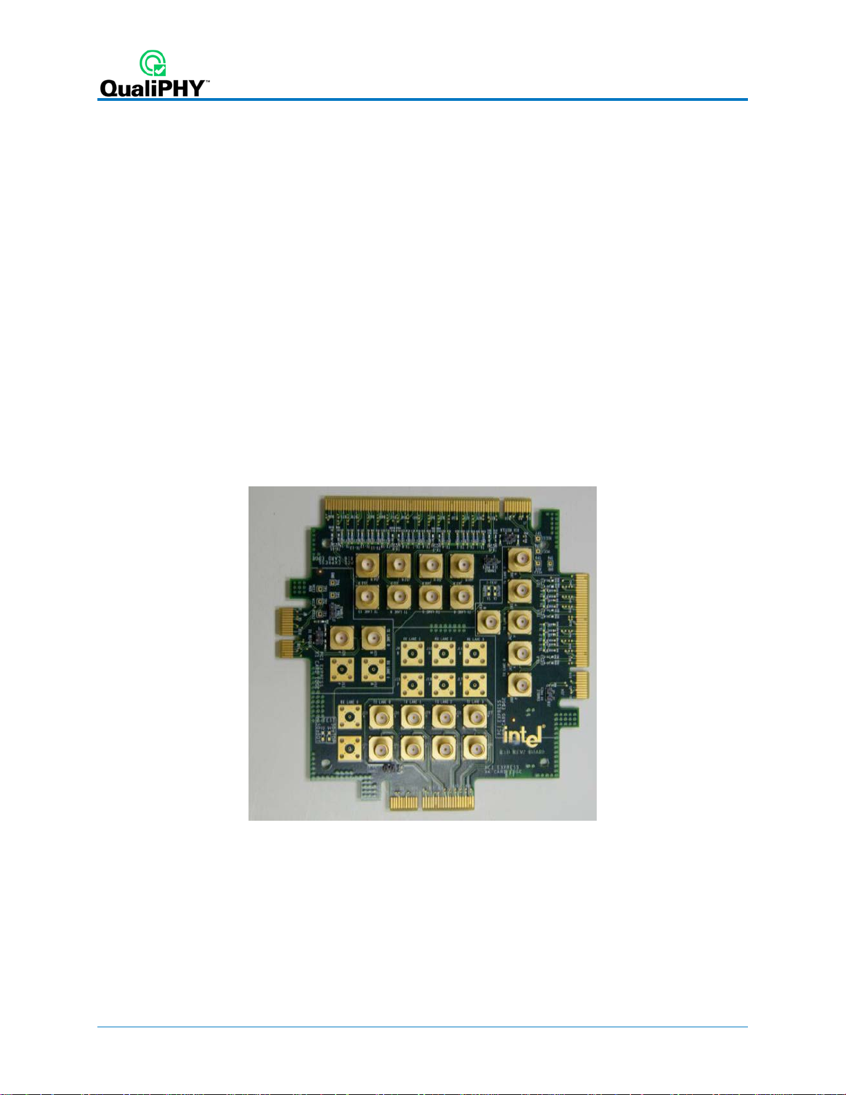
The compliance load board (CLB1) provides probing access for 1, 4, 8 and 16 lane connectors
that connect to Gen 1.1 system boards. This is used for testing system boards that only perform
at 2.5GT/s.
Figure 1. Compliance Load Board for 1, 4, 8 and 16 lane connectors (CLB1).
2 922543 Rev Error! Reference source not found.
Page 7
QPHY-PCIE Operator’s Manual
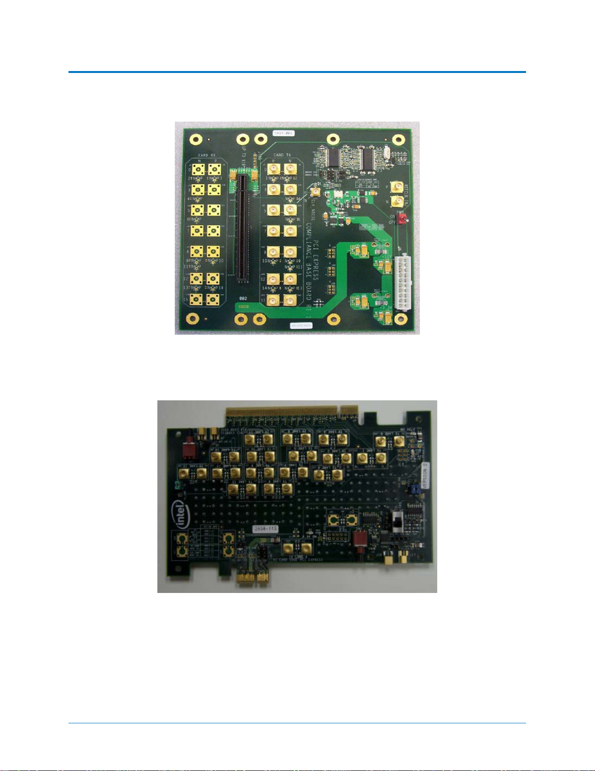
The compliance base board (CBB1) provides probing access for 1, 4, 8 and 16 lane connectors
that connect to Gen 1.1 add-in cards. This is used for testing add-in cards that only perform at
2.5GT/s.
Figure 2. Compliance Base Board for 1, 4, 8 and 16 lane connectors (CBB1).
The compliance load board (x1/x16 CLB2) provides probing access for 1 and 16 lane
connectors that connect to Gen 2.0 system boards.
Figure 3. Compliance Load Board for 1 and 16 lane connectors (x1/x16 CLB2).
922543 Rev Error! Reference source not found. 3
Page 8
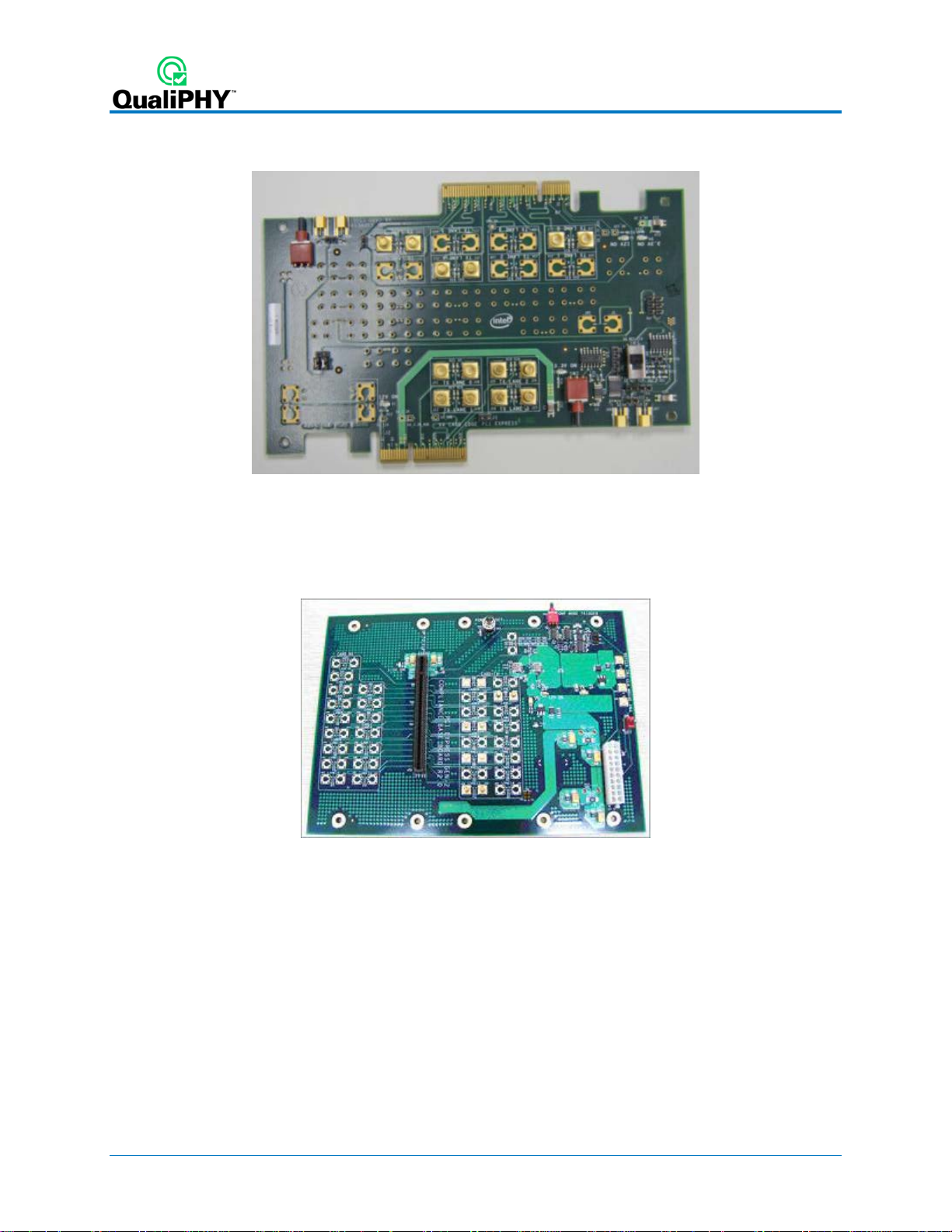
The compliance load board (x4/x8 CLB2) provides probing access for 4 and 8 lane connectors
that connect to Gen 2.0 system boards.
Figure 4. Compliance Load Board for 4 and 8 lane connectors (x4 /x8 CL B2).
The compliance base board (CBB2) provides probing access for 1, 4, 8 and 16 lane connectors
that connect to Gen 2.0 add-in cards. Also, the CBB2 provides a clean reference clock and
clock noise injection capabilities.
Figure 5. Compliance Base Board for 4 and 8 lane connectors (CBB2).
4 922543 Rev Error! Reference source not found.
Page 9

QPHY-PCIE Operator’s Manual
Required Host Computer System
Usually, the oscilloscope is the host computer for the QualiPHY software, and all models that
meet the acquisition requirements will also meet the host system requirements. However, if you
wish to run the QualiPHY software from a remote computer, these minimum requirements apply:
• Operating System:
o Windows 2000 Professional with service pack 4
o Windows XP Professional with service pack 2
o Windows VISTA with service pack 1
o Windows 7 Professional
• 1 GHz or faster processor
• 1 GB (32-bit) or 2 GB (64-bit) of RAM
• Ethernet (LAN) network capability
• Hard Drive:
o At least 100 MB free to install the framework application
o Up to 1GB per standard installed to store the log database (each database grows
from a few MB to a maximum of 1 GB)
See Set Up Remote Control
for configuration instructions.
922543 Rev Error! Reference source not found. 5
Page 10

Installation and Setup
QualiPHY is a Windows-based application that can be configured with one or more serial data
compliance components. Each compliance component is purchased as a software option.
Install Base Application
Download the latest version of the QualiPHY software from:
teledynelecroy.com/support/softwaredownload under Oscilloscope Downloads > Software Utilities
If the oscilloscope is not connected to the Internet, copy the installer onto a USB memory stick
with at least 30MB free space, then transfer it to the oscilloscope desktop or a folder on a D:\
drive to execute it.
Run QualiPHYInstaller.exe and follow the installer prompts. Choose all the components you
plan to activate. If you omit any components now, you will need to update the installation to
activate them later.
Note: Any previous installations of X-Replay, the QualiPHY base application, are overwritten
during the installation process.
By default, the oscilloscope appears as local host when QualiPHY is executed on the
oscilloscope. Follow the steps under Add Connection to QualiPHY
is 127.0.0.1.
to check that the IP address
Activate Components
The serial data compliance components are factory installed as p ar t of the main application in
your oscilloscope and are individually activated through the use of an alphanumeric code
uniquely matched to the oscilloscope’s serial number. This option key code is what is delivered
when purchasing a software option.
To activate a component on the oscilloscope:
1. From the menu bar, choose Utilities > Utilit ie s Setup.
2. On the Options tab, click Add Key.
3. Use the Virtual Keyboard to Enter Option Key, then click OK.
If activation is successful, the key code now appears in the list of Installed Option Keys.
4. Restart the oscilloscope application by choosing File > Exit, then double-clicking the
Star t DSO icon on the desktop.
6 922543 Rev Error! Reference source not found.
Page 11

QPHY-PCIE Operator’s Manual
Set Up Dual Monitor Display
Teledyne LeCroy recommends running QualiPHY on an oscilloscope equipped with Dual
Monitor Display capability. This allows the waveform and measurements to be shown on the
oscilloscope LCD display while the QualiPHY application and test results are displayed on a
second monitor.
See the oscilloscope Operator’s Manual or Getting Started Manual for instructions on setting up
dual monitor display.
Set Up Remote Contr ol
QualiPHY software can be executed from a remote host computer, controlling the oscilloscope
through a LAN Connection. To set up remote control:
• The oscilloscope must be connected to a LAN and assigned an IP address (fixed or
dynamic).
• The host computer must be on the same LAN as the oscilloscope.
Note: LXI, GPIB, LSIB, and USBTMC remote control is available for some model instruments.
Follow the same procedure, selecting the appropriate connection type on the oscilloscope and
in QualiPHY.
Configure Oscilloscope for Remot e Cont rol
1. From the menu bar, choose Utilities Utilities Setup...
2. Open the Remote tab and set Remote Control to TCP/IP.
3. Verify that the oscilloscope shows an IP address.
Add Connection to QualiPHY
1. On the host PC, download and run QualiPHYInstaller.exe.
2. Start QualiPHY and click the General Setup button.
3. On the Connection tab, click Scope Selector.
4. Click Add and choose the connection type. Enter the oscilloscope IP address from Step
3 above. Click OK.
5. When the oscilloscope is properly detected, it appears on the Scope Selector dialog.
Select the connection, and click OK.
QualiPHY is now ready to control the oscilloscope.
Select Connection
Multiple oscilloscopes may be accessible to a single remote host. In that case, go to General
Setup and use the Scope Selector at the start of the session to choose the correct connection.
QualiPHY tests the oscilloscope connection when starting a test. The system warns you if there
is a connection problem.
922543 Rev Error! Reference source not found. 7
Page 12

Using QualiPHY
This section provides an overview of the QualiPHY user interface and general procedures,
using examples from the QPHY-BroadR-Reach option. For detailed information about the
QPHY-PCIE software option, see QPHY-PCIE Testing
Accessing the Softw ar e
Once QualiPHY is installed and activated, it can be accessed from the oscilloscope menu bar by
choosing Analysis > QualiPHY, or by double-clicking the QualiPHY desktop icon on a remote
computer.
The QualiPHY framework dialog illustrates the overall software flow, fro m general set up through
running individual compliance tests. Work from left to right, making all desired settings on each
sub-dialog.
.
Figure 6 - QualiPHY framework dialog and Standard selection menu.
The sub-dialogs are organized into tabs each containing configuration controls related to that
part of the process. These are described in more detail in the following sections.
If Pause on Failure is checked, QauliPHY prompts to retry a measure whenever a test fails.
Report Generator launches the manual report generator dialog.
The Exit button at the bottom of the framework dialog closes the QualiPHY application.
8 922543 Rev Error! Reference source not found.
Page 13

QPHY-PCIE Operator’s Manual
General Setup
The first sub-dialog contains general system settings. These remain in effect for each session,
regardless of Standard, until changed.
Connection tab
Shows IP Address of the oscilloscope (local host 127.0 .0.1 if QualiPHY is run from the
oscilloscope). The Scope Selector allows you to choose the oscilloscope used for testing when
several are connected to the QualiPHY installation. See Set Up Remote Control
Session Info tab
Optional information about the test session that may be added to reports, such as: Operator
Name, Device Under Test (DUT), Temperature (in °C) of the test location, and any additional
Comments. There is also an option to Append Results or Replace Results when continuing a
previous session.
To optimize report generation, enter at least a DUT name at the beginning of each session.
Report tab
Settings related to report generation. Choose:
for details.
• Reporting behavior of:
o “Ask to generate a report after tests,” where you’ll be prompted to create a new
file for each set of test results.
o “Never generate a report after tests,” where you’ll need to manually execute the
Report Generator to create a report.
o “Always generate a report after tests,” to autogenerate a report of the latest test
results.
• Default report output format of XML, HTML, or PDF.
• A generic Output file name, including the full path to the report output folder.
Optionally, check Allow sty le sheet selection in Report Generator to enable the use of a
custom .xslt when generating reports (XML and HTML output only). The path to the .xslt is
entered on the Report Generator dialog.
Report Generator launches the Report Generator dialog, which contains the same settings as
the Report tab, only applied to individual reports.
Advanced tab
This tab launches the X-Replay Mode dialog. See X-Replay Mode.
About tab
Information about your QualiPHY installation.
922543 Rev Error! Reference source not found. 9
Page 14

QualiPHY Test Process
Once general system settings are in place, these are the steps for running test sessions.
Set Up Test Session
1. Connect the oscilloscope to the DUT. See QPHY-PCIE Testing Physical Setup.
2. Access the QualiPHY software to display the framework dialog.
3. If running QualiPHY remotely, click General Setup and open the Scope Selector to
select the correct oscilloscope connection.
4. If you have more than one component activated, click Standard and select the desired
standard to test against. Otherwise, your one activated component will appear as the
default selection.
Note: Although all the QualiPHY components appear on this dialog, only those activated
on the oscilloscope are enabled for selection.
5. Click the Configuration button and select the test configuration to run. T hese preloaded configurations are set up to run all the tests required for compliance and provide
a quick, easy way to begin compliance testing. See QPHY-PCIE Test Configurations
a description of your configurations.
You can also create custom configurations for internal compliance tests by copying and
modifying the pre-loaded configurations. See Customizing QualiPHY
for details.
for
6. Close the Edit/View Configuration dialog to return to the framework dialog.
Run Tests
1. On the framework dialog, click Start to begin testing.
When tests are in progress, this button changes to Stop. Click it at any time to stop the
test in process. You’ll be able to resume from the point of termination or from the
beginning of the test.
2. Follow the pop-up window prompts. QualiPHY guides you step-by-step through each of
the tests described in the standard specification, including diagrams of t he connection to
the DUT for each required test mode.
3. When all tests are successfully completed, both progress bars on the framework dialog
are completely green and the message “All tests completed successfully” appears. If
problems are encountered, you’ll be offered options to:
• Retry the test from the latest established point defined in the script
• Ignore and Continue with the next test
• Abort Session
10 922543 Rev Error! Reference source not found.
Page 15

QPHY-PCIE Operator’s Manual
Run Reports
The QualiPHY software automates report generation. On the framework dialog, go to General
Setup > Report to pre-configure reporting behavior. You can also manually launch the Report
Generator from the framework dialog.
The Report Generator offers the same selections as the Report tab, only applied to each report
individually, rather than as a system setting. There are also options to link a custom style sheet
(.xslt) to the report, or to Exclude Informative Results.
The Test Report includes a summary table with links to the detailed test result pages.
Figure 7 - The Test Report Summary and Details pages.
Reports are output to the base installation folder *\LeCroy\XReplay\Reports.
You can add your own logo to the report by replacing the file
*\LeCroy\XReplay\StyleSheets\CustomerLogo.jpg.
The recommended maximum size is 250x100 pixels at 72 ppi, 16.7 million colors, 24 bits. Use
the same file name and format.
922543 Rev Error! Reference source not found. 11
Page 16

Customizing QualiPHY
The pre-loaded configurations cannot be modified. However, you can create your own test
configurations by copying one of the pre-loaded configurations and modifying it.
Copy Configuration
1. Access the QualiPHY framework dialog and select a Standard.
2. Click Edit/View Configuration and select the configuration upon which to base the new
configuration. This can be a pre-loaded configuration or another copy.
3. Click Copy and enter a name and description. Once a custom configuration is defined, it
appears on the Configuration tab followed by “(Copy).”
4. Select the new, custom configuration and follow the procedures below to continue
making changes.
Note: If any part of a configuration is changed, the Save As button becomes active on
the bottom of the dialog. If a custom configuration is changed, the Save button will also
become active to apply the changes to the existing configuration.
Select Tests
On the Test Selector tab, select/deselect the tests that make up the configuration. Each test is
defined by the PCI CEM standard. A description of each test is displayed when it is selected.
To loop any of the tests in this configuration, select the test fr om the list, then choose to loop
indefinitely until stopped or enter the number of repetitions.
12 922543 Rev Error! Reference source not found.
Page 17

QPHY-PCIE Operator’s Manual
Edit Variables
The Variable Setup tab contains a list of test variables. See QPHY-PCIE Variables for a
description of each.
To modify a variable:
1. Select the variable on the Variable Setup tab, then click Edit Variable. (You can also
choose to Reset to Default at any time.)
2. The conditions of this variable appear on a pop-up. Choose the new condition to apply.
922543 Rev Error! Reference source not found. 13
Page 18

Edit Test Limits
The Limits tab shows the Limit Set currently associated with the configuration. Any limit set can
be associated with a custom configuration by selecting it in this field.
The Limits Manager shows the settings for every test limit in a limit se t. Those in the default
Compliance Limits set are the limits defined by the standard.
To cre ate a custom l i mit set:
1. On the Limits tab, click Limits Manager.
2. With the default set selected, click Copy Set and enter a name.
Note: You can also choose to copy and/or modify another custom set that has been
associated with this configuration.
3. Double click the limit to be modified, and in the pop-up enter the new values.
You can also Import Limits from a .csv file. Navigate to the file location after clicking the
button.
Tip: Likewise, Export Limits creates a .csv f ile from the current limit set. You may wish to
do this and copy it to format the input .csv file.
14 922543 Rev Error! Reference source not found.
Page 19

QPHY-PCIE Operator’s Manual
X-Replay Mode
The X-Replay mode window is an advanced (“developer”) view of QualiPHY. The tree in the
upper-left frame enables you to navigate to processes in the PCIE test script, in case you need
to review the code, which appears in the upper-right frame.
Two other partic u la r ly usef u l features are:
• A list of recent test sessions in the lower-left frame. While you can only generate a
report of the current test session in the QualiPHY wizard, in X-Replay Mode you can
generate a report for any of these recent sessions. Right-click on the session and
choose Create Report from context menu.
• The QualiPHY log in the bottom-right frame. The frame can be split by dragging up the
lower edge. The bottom half of this split frame now shows the raw Python output, which
can be useful if ever the script needs debugging.
Figure 8 – X-Replay Mode window.
922543 Rev Error! Reference source not found. 15
Page 20

QPHY-PCIE Testing
Test Preparation
Before beginning any test or data acquisition, warm the oscilloscope for at least 20 minutes.
Calibration is automatic under software control and no manual calibration is required. This
procedure will be run again if the oscilloscope temperature changes by more than a few degrees.
Required Test Modes
The QPHY-PCIE script requires that you place the DUT in the required test modes. The scr ipt
will prompt you to do so before each test, but it is recommended that you ensure the DUT is
capable of being placed in the required test modes before beginning testing.
Physical Setup
See the description of each test configuration for specific set up information.
QPHY-PCIE Test Configurations
Test configurations include variable settings, limit sets, and test selections.
For detailed descriptions of calibration and testing, please refer to the Teledyne LeCroy PCIE
Gen1 and Gen2 test procedures on PCISIG.com and the official test specification, PCI Express
Card Electromechanical Specif icat ion, Rev. 3.0.
2.5 GTs Clock Jitter Test
This configuration runs only Test 1.6 Clock Jitter for 2.5Gbps signals. Variations exist for
different source configurations: differential inputs on Input A or Input B, and single inputs on
Input A or Input B. This test requires the use of the PCI Express Clock Phase Jitter Test
Software, which can be downloaded from:
http://www.pcisig.com/specifications/pciexpress/compliance/compliance_library
Demo
This configuration runs all the Transmitter tests using waveforms saved on the oscilloscope in
D:\PCIe\Demo and the default limit set, Compliance Limits. This configuration is meant to easily
demonstrate the QPHY-PCIE capabilities when live signals cannot be tested. You will see
dialogs and connection diagrams similar to what you would see during an actual t est.
Empty Template
This configuration includes all tests and default variable settings specified in the PCIe standard.
It is meant to serve as a basis for creating custom configurations. The limit set in use is PCIe
2.1. Copy and save it with a unique name, then follow the steps in Customizing QualiPHY
modify the new configuration.
to
Signal Qualit y Tes t (CEM) , Add-in Ca rd
This configuration is meant to run all of the transmitter tests on a PCIe Add-In card. All the
variables are set to default, except Device T ype is set to “Add-In” and CleanClock is set to “Yes”.
The limit set used is PCIe 2.1. Both 2.5Gbps and 5.0Gbps Signal Quality tests are run.
16 922543 Rev Error! Reference source not found.
Page 21

QPHY-PCIE Operator’s Manual
Variations exist for different source configurations: differential inputs on Input A or Input B, and
single inputs on Input A or Input B.
Signal Qualit y Tes t (CEM) , Sys tem
This configuration is meant to run all of the transmitter tests on a PCIe System board. All the
variables are set to default. The limit set is use is PCIe 2.1. Both 2.5Gbps and 5.0Gbps Signal
Quality tests are run. Variations exist for different source configurations: differential inputs on
Input A or Input B, and single inputs on Input A or Input B.
QPHY-PCIE Test Descriptions
2.5 GT/s Signal Quality Tests
These tests use the “PCIe Compliance” Signal Type selection from the SDA II analysis software.
When “PCIe Compliance” is selected, SDA II uses the SigTest DLL in the background to
generate the Eye Diagrams and the Jitter results. This can only be done using 2.5GT/s signals.
• Mean Unit Interval
• Max Unit Interval
• Min Unit Interval
• Min Time Between Crossovers
• Data Rate
• Per Edge RMS Jitter
• Mean Median to Peak Jitter
• Max Median to Peak Jitter
• Min Median to Peak Jitter
• Mean peak-to-peak jitter
• Max peak-to-peak jitter
• Min peak-to-peak jitter
• Minimum transition eye voltage
• Maximum transition eye voltage
• Minimum non-transition eye voltage
• Maximum non-transition eye voltage
• Minimum transition eye voltage margin above eye
• Minimum transition eye voltage margin below eye
• Minimum non-transition eye voltage margin above eye
• Minimum non-transition eye voltage margin above eye
• Transition eye mask violations
• Non-transition eye mask violations
• Minimum Eye Width
• Differential peak to peak voltage
922543 Rev Error! Reference source not found. 17
Page 22

5.0 GT/s Signal Quality Tests
The following tests are run on the 5.0GT/s compliance pattern with 3.5dB of de-emphasis and
also with 6.0dB of de-emphasis.
• Mean Unit Interval
• Min Time Between Crossovers
• Data Rate
• Max Peak to Peak J i tter
• Total J itter at BER of 10e-12
• Deterministic Jitte r Delta -Delta
• Random Jitter (RMS)
• Minimum Transition Eye Voltage
• Maximum Transition Eye Voltage
• Minimum Non Transition Eye Voltage
• Maximum Non Transition Eye Voltage
• Minimum Transition Eye Voltag e Margin Above Eye
• Minimum Transition Eye Voltage Margin Below Eye
• Maximum Non Transition Eye Voltage Margin Above Eye
• Maximum Non Transition Eye Voltage Margin Below Eye
• Mask Violations Transition Eye
• Mask Violations Non Transition Eye
These tests use the SigTest analysis package that is built into the oscilloscope software. The
SigTest settings are set to be the same as when the SigTest software runs independently.
• Bit Rate = 5.0 GHz
• BER = -12
• Eye Type = Monochrome
• UIsPerEye = 1.67UI
• Jitter Filter Settings
o Order = Brick Wall
o Corner Freq = 1.5 MHz
o Damping = 707.11e-3
o Extra Pole = 0 Hz
o Delay = 0 fs
• Standard = PCIe2.0 Compliance
• Masks
o System Testing = System Dual Port 250mV
o Add-in Card 3.5dB Testing = Add-in card 3.5dB
o Add-in Card 6.0dB Testing = Add-in card 6.0dB
18 922543 Rev Error! Reference source not found.
Page 23

QPHY-PCIE Operator’s Manual
QPHY-PCIE Variables
CLEAN CLOCK
This variable allows the user to select whether or not they are using a clean clock. This variable maps
directly to the clean clock variable in SigTest. When set to Yes, this variable guarantees that the clock
does not have SSC and is known to be good. This variable should be set to Yes for add in card testing
(using a CBB, which generates the clock), and No for a system board test (because the System board
generates the clock). This control is only of use in the 2.5GT/s testing. The new SigTest algorithm for 5G
does not ask for this input. The default value for this variable is No.
D
ESKEW VALUE IN PICOSECONDS
This variable allows the user to specify the channel + cable deskew between channels C2 and
C3. The value is in picoseconds and is applied to the channel C2. This value is only applied to
C2 if “User Defined” is selected for the Deskew measure mode method variable.
D
ESKEW MEASURE MODE METHOD
This variable allows the user to select the method for deskewing their cables. The choices for
this variable are “Wizard Method” and “User Defined.” “Wizard Measured” is used to launch the
automated deskew measurement. “User Defined” is used if the user would like to set the
Deskew value in picoseconds variable when the deskew value is already known. The default
value for this variable is “Wizard Method.”
D
EVICE TYPE
This variable allows the user to select whether device type is a System Board or an Add-in
Card. When testing System Boards both the clock signal and the data signal must be captured
simultaneously . When testing Add-In Cards only the data signal is required for testing. The
default value for this variable is System.
F
ORMFACTOR
This variable allows the user to select whether their form factor is Desktop or Mobile. This
variable maps directly to the form factor variable in SigTest. The default value is Desktop.
S
AVED WAVEFORM PATH
This variable allows the user to specify the path that saved waveforms are recalled from when
running in demo mode or when TestMode is “Use Saved Data.” The default value for this
variable is “D:\Waveforms\PCIe.”
Waveforms are saved in a directory with the name of the Device Under Test, under this path.
The saved waveforms have a channel name prefix (such as "C2") followed by the bit rate,
deemphasis setting, and lane number; and the extension ".trc". For example:
C2_2.5GT_3.5dB_L0.trc. If the Test Mode variable is set to Use Saved Data the script will look
for files in the appropriate directory and with exactly these names, to repeat the tests using
previously saved data.
T
EST MODE
This variable allows the user to decide whether the tests should be run on newly acquired data
or if previously saved waveforms should be used. The choices for this variable are “Acquire
New Data” and “Use Saved Data.” If “Use Saved Data” is selected, the waveforms are recalled
from the location specified in the Saved Waveform Path variable. The default value for t his
variable is “Acquire New Data.”
922543 Rev Error! Reference source not found. 19
Page 24

QPHY-PCIE Limit Sets
The default installation of QPHY-PCIE contains only one limit set, called PCIe 2.1 This set
contains all of the limits for PCIe 1.1a and PCIe 2.1.
Manual Deske wing Procedures
This section is only applicable to the oscilloscope and the cables connecting to the oscilloscope
channels. Note that the cables connecting the PeRT3 to the fixture or to the DUT must be
phase matched within a tight tolerance because the PeRT, like any generator, does not have the
capability to compensate for mismatched cables connected to its outputs.
Cable Deskewing Using the Fast Edge Output
The following procedure demonstrates how to manually deskew two oscilloscope channels and
cables using the fast edge output, with no need for any T connector or adapters. This can be
done once the temperature of the oscilloscope is stable. The oscilloscope must be warm ed up
for at least a half-hour before proceeding. This procedure should be run again if the temperature
of the oscilloscope changes by more than a few degrees.
For the purpose of this procedure, the two channels being deskewed are referred to as Channel
X and Channel Y. The reference channel is Channel X and the channel being deskewed is
Channel Y.
1. Begin by recalling the Default Oscilloscope Setup.
2. Configure the oscilloscope as follows:
• Timebase
i.Fixed Sample Rate
ii.Set the Sample Rate to 40 GS/s
iii.Set the Time/Division to 1 ns/div
• Channels
i. Turn on Channel X and Channel Y.
ii. Set V/ div for Channel X and Channel Y to 100mV/div.
iii. Set the Averaging of Channel X and Channel Y to 500 sweeps.
iv. Set the Interpolation of Channel X and Channel Y to Sinx/x.
20 922543 Rev Error! Reference source not found.
Page 25

• Trigger
i.Configure to Source to be FastEdge.
ii.Set the Slope to Positive.
• Parameter Measurements:
i. Set the source for P1 to CX and the measure to Delay.
ii. Set the source for P2 to CY and the measure to Delay.
iii. Set the source for P3 to M1 and the measure to Delay.
3. Set the display to Single Grid.
QPHY-PCIE Operator’s Manual
• Click Display Single Gr id .
4. Using the appropriate adapter, connect Channel X to the Fast Edge Output of the
oscilloscope.
5. Adjust the Trigger Delay so that the Channel X signal crosses at the center of the
screen.
6. Change the Timebase to 50 ps/div.
7. Fine tune the Trigger Delay so that the Channel X signal crosses at the exact center of
the screen.
8. Press the Clear Sweeps button on the front panel to reset the averaging.
9. Allow multiple acquisitions to occur until the waveform is stable on the screen.
922543 Rev Error! Reference source not found. 21
Page 26

10. Save Channel X to M1.
• Click File Save Waveform.
• Set Save To Memory.
• Set the Source to CX.
• Set the Destination to M1.
• Click Save Now.
11. Disconnect Channel X from the Fast Edge Output and connect Channel Y to the Fast
Edge Output.
12. Press the Clear Sweeps button on the front panel to reset the averaging.
13. Allow multiple acquisitions to occur until the wavefor m is stable on the screen.
14. From the Channel Y menu, adjust the Deskew of Channel Y until Channel Y is directly
over the M1 trace.
15. Ensure that P3 and P2 are reasonably close to the same value. (Typically < 5ps
difference)
22 922543 Rev Error! Reference source not found.
Page 27

QPHY-PCIE Operator’s Manual
Cable Deskewing Without Using the Fast Edge Output
The following procedure demonstrates how to manually deskew two oscilloscope channels and
cables using the differential data signal, with no need for any T connector or adapters.
This can be done once the temperature of the oscilloscope is stable. The oscilloscope must be
warmed up for at least a half-hour before proceeding. This procedure should be run again if the
temperature of the oscilloscope changes by more than a few degrees.
1. Connect a differential data signal to C1 and C2 using two approximately matching
cables. Set up the oscilloscope to use the maximum sample rate. Set the timebase for a
few repetitions of the pattern (at least a few dozen edges).
2. On the C3 menu, check Invert. Now C1 and C2 should look the same.
3. Using the Measure Setup, set P1 to measure the Skew of C1, C2. Turn on Statistics
(Measure menu). Write down the mean skew value after it stabilizes. This mean skew
value is the addition of Data skew + cable sk ew + channel skew.
4. Swap the cable connections on the Data source side (on the test fixture), and then press
the Clear Sweeps button on the oscilloscope (to clear t he accumulated statistics; since
we changed the input).
5. Write down the mean skew value aft er it stabilizes. This mean skew value is the addition
of (-Data skew) + cable skew + channel skew.
6. Add the two mean skew values and divide the sum in half:
UU [Data skew + cable skew + channel skew] + [ (-Data skew) + cable skew + channel skew]UU
2
The above formula simplifies to:
[cable skew + channel skew]
7. Set the resulting value as the Deskew value in C1 menu.
8. Restore the cable connections to their Step 1 settings (previous). Press the Clear
Sweeps button on the oscilloscope. The mean skew value should be approximately zero
- that is the data skew. Typicall y, results are <1ps given a test fixture meant to minimize
skew on the differential pair.
9. On the C2 menu, clear the Invert checkbox and turn off the parameters.
922543 Rev Error! Reference source not found. 23
Page 28

In the previous procedure, we used the default setup of the Skew parameter (which is detecting
positive edges on both signals at 50%). We also inverted C2 in order to make C1 and C2 both
have positive edges at the same time.
Alternately, we clearly could have not inverted C2 and instead selected the Skew clock 2 tab in
the P1 parameter menu and set the oscilloscope to look for negative edges on the second input
(C2). However, we believe that the previous procedure looks much more aesthetically pleasing
from the display as it shows C2 and C3 with the same polarity.
Figure 9 - The Skew parameter right side dialog, Skew clock 2 tab, showing default setup.
24 922543 Rev Error! Reference source not found.
Page 29

QPHY-PCIE Operator’s Manual
Error Messages
These messages may appear when using QualiPHY.
“Warning, no valid technology package has been found…” This message appears if none
of the QualiPHY components have been activated on the oscilloscope before launching the
QualiPHY application. See Activate Components.
“No devices connected to the application or device not alive…” This message appears if
you are running QualiPHY from a remote PC, but a) you have not connected any oscilloscopes
to the installation, or b) the oscilloscopes are offline. See Set Up Remote Control
oscilloscope.
“This test requires Firmware version x.x.x.x or higher.” The test oscilloscope firmware
needs to be updated. Go to teledynelecroy.com/support/softwaredownload under Oscilloscope
Downloads > Firmware Update to download the latest firmware.
“An <oscilloscope model> or better is required for <test>.” The test cannot be run with this
oscilloscope. If using remote control, you may be able to choose another oscilloscope
connection.
“This test requires the <name> option.” Besides the QualiPHY component, you must
purchase and activate the named software option on the oscilloscope.
to connect an
922543 Rev Error! Reference source not found. 25
Page 30

 Loading...