

Page 1

QPHY-HDMI
Operator’s Manual
Revision A – December, 2013
Relating to the following release versions:
Software Version Rev. 7.3.x.x
Script HDMI.IRT
Style Sheet Rev. 1.2
Page 2

700 Chestnut Ridge Road
Chestnut Ridge, NY, 10977-6499
Tel: (845) 425-2000, Fax: (845) 578 5985
teledynelecroy.com
© 2013 Teledyne LeCroy, Inc. All rights reserved.
Teledyne LeCroy and other product or brand names are trademarks or requested trademarks of their
respective holders. Information in this publication supersedes all earlier versions. Specifications are
subject to change without notice.
922540 Rev A
December, 2013
Page 3

QPHY-HDMI Operator’s Manual
Table of Contents
Introduction ............................................................................................................................... 1
About QualiPHY ............................................................................................................................................ 1
About QPHY-HDMI ....................................................................................................................................... 1
Required Hardware ....................................................................................................................................... 1
Test Fixtures .................................................................................................................................................. 2
Required Host Com puter S yst em ................................................................................................................. 2
Installation and Setup ............................................................................................................... 3
Install Base Application ................................................................................................................................. 3
Activate Components .................................................................................................................................... 3
Set Up Dual Monitor Display ......................................................................................................................... 3
Set Up Remote Control ................................................................................................................................. 4
Configure Oscilloscope for Remote Control .......................................................................................... 4
Add Connection to QualiPHY ................................................................................................................ 4
Select Connection .................................................................................................................................. 4
Using QualiPHY ......................................................................................................................... 5
Accessing the Software ................................................................................................................................. 5
General Setup ............................................................................................................................................... 6
Connection tab ....................................................................................................................................... 6
Session Info tab ..................................................................................................................................... 6
Report tab .............................................................................................................................................. 6
Advanced tab ......................................................................................................................................... 6
About tab ................................................................................................................................................ 6
QualiPHY Test Process ................................................................................................................................. 7
Set Up Test Session .............................................................................................................................. 7
Run Tests ............................................................................................................................................... 8
Run Reports ........................................................................................................................................... 9
Customizing QualiPHY ................................................................................................................................ 10
Copy Configuration .............................................................................................................................. 10
Select Tests ......................................................................................................................................... 10
Edit Variables ....................................................................................................................................... 11
Edit Test Limits .................................................................................................................................... 12
X-Replay Mode ........................................................................................................................................... 13
QPHY-HDMI Testing ................................................................................................................ 14
Test Preparation .......................................................................................................................................... 14
Required Test Modes .......................................................................................................................... 14
Physical Setup ..................................................................................................................................... 14
Deskew ................................................................................................................................................ 14
QPHY-HDMI Test Configurations ................................................................................................................ 15
Clock and Data0 Basic Tests ............................................................................................................... 15
Clock and Data0 Tests at All Standard Frequencies ........................................................................... 15
Data0 & Data1 & Data2 Inter-Pair Skew (7-6) ..................................................................................... 15
Clock and Data0 Tests at Custom Frequency (340 MHz) ................................................................... 15
Demo of All Tests................................................................................................................................. 15
QPHY-HDMI Test Descriptions ................................................................................................................... 16
Test7-2: TMDS-VL ............................................................................................................................... 16
Test7-4: TMDS TRise, TFall ................................................................................................................ 17
Test7-5: TMDS Over/Undershoot ........................................................................................................ 17
Test7-6: TMDS Inter-P air S kew ........................................................................................................... 18
Test7-7: TMDS Intra-P air S kew ........................................................................................................... 19
Test7-8: TMDS Clock Duty Cycle ........................................................................................................ 20
922540 Rev A i
Page 4

Test7-9: TMDS Clock Jitter .................................................................................................................. 21
Test7-10: TMDS Data Eye Diagram .................................................................................................... 22
QPHY-HDMI Variables ................................................................................................................................ 23
Specific to “Test7-2: TMDS-VL” Group ................................................................................................ 24
Specific to “Test7-4: TMDS TRise, TFall” Group ................................................................................. 24
Specific to “Test7-6: TMDS Inter-Pair Skew” Group ............................................................................ 24
Specific to “Test7-7: TMDS Intra-Pair Skew” Group ............................................................................ 25
Specific to “Test7-8: TMDS Clock Duty Cycle” Group ......................................................................... 25
Specific to “Test7-9: TMDS-Clock Jitter” Group .................................................................................. 25
Specific to “Test7-10: TMDS-Data Eye Diagram” Group ..................................................................... 26
QPHY-HDMI Limit Sets ............................................................................................................................... 26
Manual Deskewing Procedures.............................................................................................. 27
Cable Deskewing Using the Fast Edge Output........................................................................................... 27
Cable Deskewing Using the DUT Signal .................................................................................................... 30
Error Messages ....................................................................................................................... 32
Table of Figures
Figure 1 - QualiPHY framework dialog and Standard selection menu. ................................................. 5
Figure 2 - The Test Report Summary Table and Detail page. ................................................................. 9
Figure 3 – X-Replay Mode window. ......................................................................................................... 13
Figure 4 - The Skew parameter right side dialog, Skew clock 2 tab, showing default setup. ........... 31
About This Manual
This manual assumes that you are familiar with using an oscilloscope−in particular the Teledyne
LeCroy oscilloscope that will be used with QualiPHY−and that you have purchased the QPHYHDMI software option. Some of the images in this manual may show QualiPHY products other
than QPHY-HDMI, or were captured using different model oscilloscopes, as they are meant to
illustrate general concepts only. Rest assured that while the user interface may look different
from yours, the functionality is identical.
ii 922540 Rev A
Page 5

QPHY-HDMI Operator’s Manual
Introduction
About QualiPHY
QualiPHY is highly automated compliance test software meant to help you develop and validate
the PHY (physical-electrical) layer of a device, in accordance with the official documents
published by the applicable standards organizations and special interest groups (SIGs). You can
additionally set custom variables and limits to test compliance to internal standards.
QualiPHY is composed of a “framework” application that enables the configuration and control
of separate tests for each standard through a common user interface. Features include:
• Multiple Data Source Capability: Connect to your X-Stream oscilloscope via LAN or
other interfaces.
• User-Defined Test Limits: Tighten limits to ensure devices are well within the passing
region, even if subsequently measured with different equipment.
• Flexible Test Results Reporting that includes XML Test Record Generation.
Understand a device performance distribution, or obtain process related information from
the devices under test.
About QPHY-HDMI
QPHY-HDMI is an automated test package performing all the normative, real-time oscilloscope
tests for sources in accordance with version 1.4 of the High Definition Multimedia Interface
Compliance Test Specification (HDMI).
The software can be run on any Teledyne LeCroy oscilloscope with at least 8 GHz bandwidth
(for testing clock rates above 148.5 MHz). The oscilloscope must also have the QualiPHY
software installed and the QPHY-HDMI software option activated.
Required Hardware
• Real-time Teledyne LeCroy oscilloscope with all required software installed.
Note: QPHY-HDMI tests are designed to run on WavePro/SDA/DDA 7Zi/ZI-A,
WaveMaster/SDA/DDA Zi/Zi-A, LabMaster 9Zi/Zi-A Series oscilloscopes with minimum
8GHz bandwidth. The HDMI test specification requires 8 GHz bandwidth for testing clock
rates above 148.5 MHz.
• SDAII or SDAIII oscilloscope software option. (SDAII / SDIII is standard on SDA model
oscilloscopes)
• 8 SMA Male to SMA Male cables
• 4 TF-HDMI-3.3V test adapters
• HDMI test fixtur e
For the most complete and up-to-date list, see the HDMI SIG website: http://www.hdmi.org
922540 Rev A 1
Page 6

Test Fixtures
Teledyne LeCroy recommends using the Wilder Technologies HDMI-TPA-P (plug test adapter)
used in conjunction with HDMI-TPA-E (EDI D board with EEPROM). This equipment is available
from Wilder Technologies individually or as part of the HDMI-TPA-PRRCE Test Adapter Kit. The
HDMI-TPA-PRRCE test adapter kit provides a very high bandwidth, low noise evaluation vehicle
that enables high-performance characterization of both plug and receptacle HDMI™ devices
with bandwidth greatly exceeding the 340 MHz (10.2 Gbps) of the latest v1.4b HDMI
specification.
Required Host Computer System
Usually, the oscilloscope is the host computer for the QualiPHY software, and all models that
meet the acquisition requirements will also meet the host system requirements. However, if you
wish to run the QualiPHY software from a remote computer, these minimum requirements apply:
• Operating System:
o Windows 2000 Professional with service pack 4
o Windows XP Professional with service pack 2
o Windows VISTA with service pack 1
o Windows 7 Professional
• 1 GHz or faster processor
• 1 GB (32-bit) or 2 GB (64-bit) of RAM
• Ethernet (LAN) network capability
• Hard Drive:
o At least 100 MB free to install the framework application
o Up to 1GB per standard installed to store the log database (each database grows
from a few MB to a maximum of 1 GB)
See Set Up Remote Control
for configuration instructions.
2 922540 Rev A
Page 7

QPHY-HDMI Operator’s Manual
Installation and Setup
QualiPHY is a Windows-based application that can be configured with one or more serial data
compliance components. Each compliance component is purchased as a software option.
Install Base Application
Download the latest version of the QualiPHY software from:
teledynelecroy.com/support/softwaredownload under Oscilloscope Downloads > Software Utilities.
If the oscilloscope is not connected to the Internet, copy the installer onto a USB memory stick,
then transfer it to the oscilloscope desktop or a folder on a D:\ drive to execute it.
Run QualiPHYInstaller.exe and follow the installer prompts. Choose all the components you
plan to activate. If you omit any components now, you will need to update the installation to
activate them later.
By default, the oscilloscope appears as local host when QualiPHY is executed on the
oscilloscope. Follow the steps under Add Connection to QualiPHY
is 127.0.0.1.
to check that the IP address
Activate Components
The serial data compliance components are factory installed as part of the main application in
your oscilloscope and are individually activated through the use of an alphanumeric code
uniquely matched to the oscilloscope’s serial number. This option key code is what is delivered
when purchasing a software option.
To activate an option on the oscilloscope:
1. From the menu bar, choose Utilities > Utilities Setup.
2. On the Options tab, click Add Key.
3. Use the Virtual Keyboard to Enter Option Key, then click OK.
If activation is successful, the key code now appears in the list of Installed Option Keys.
4. Restart the oscilloscope application by choosing File > Exit, then double-clicking the
Start DSO icon on the desktop.
Set Up Dual Monitor Display
Teledyne LeCroy recommends running QualiPHY on an oscilloscope equipped with Dual
Monitor Display capability. This allows the waveform and measurements to be shown on the
oscilloscope LCD display, while the QualiPHY application and test results are displayed on a
second monitor.
See the oscilloscope Operator’s Manual or Getting Started Manual for instructions on setting up
dual monitor display.
922540 Rev A 3
Page 8

Set Up Remote Contr ol
QualiPHY software can be executed from a remote host computer, controlling the oscilloscope
through a LAN Connection. To set up remote c ontrol:
• The oscilloscope must be connected to a LAN and assigned an IP address (fixed or
dynamic).
• The host computer must be on the same LAN as the oscilloscope.
Note: LXI, GPIB, LSIB, and USBTMC remote control is available for some model instruments.
Follow the same procedure, selecting the appropriate connection type on the oscilloscope and
in QualiPHY.
Configure Oscilloscope for Remot e Cont rol
1. From the menu bar, choose Utilities Utilities Setup...
2. Open the Remote tab and set Remote Control to TCP/IP.
3. Verify that the oscilloscope shows an IP address.
Add Connection to QualiPHY
1. On the host PC, download and run QualiPHYInstaller.exe.
2. Start QualiPHY and click the General Setup button.
3. On the Connection tab, click Scope Selector.
4. Click Add and choose the connection type. Enter the oscilloscope IP address from Step
3 above. Click OK.
5. When the oscilloscope is properly detected, it appears on the Scope Selector dialog.
Select the connection, and click OK.
QualiPHY is now ready to control the oscilloscope.
Select Connection
Multiple oscilloscopes may be accessible to a single remote host. In that case, go to General
Setup and use the Scope Selector at the start of the QPHY session to choose the correct
connection.
QualiPHY tests the oscilloscope connection when starting a test. The system warns you if there
is a connection problem.
4 922540 Rev A
Page 9
QPHY-HDMI Operator’s Manual
Using QualiPHY
This section provides an overview of the QualiPHY user interface and general procedures. For
detailed information about the QPHY-HDMI software option, see QPHY-HDMI Testing
Accessing the Softw ar e
Once QualiPHY is installed and activated, it can be accessed from the oscilloscope menu bar
by choosing Analysis > QualiPHY, or by double-clicking the QualiPHY desktop icon on a
remote computer.
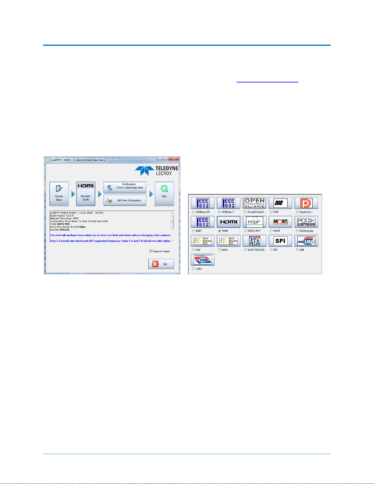
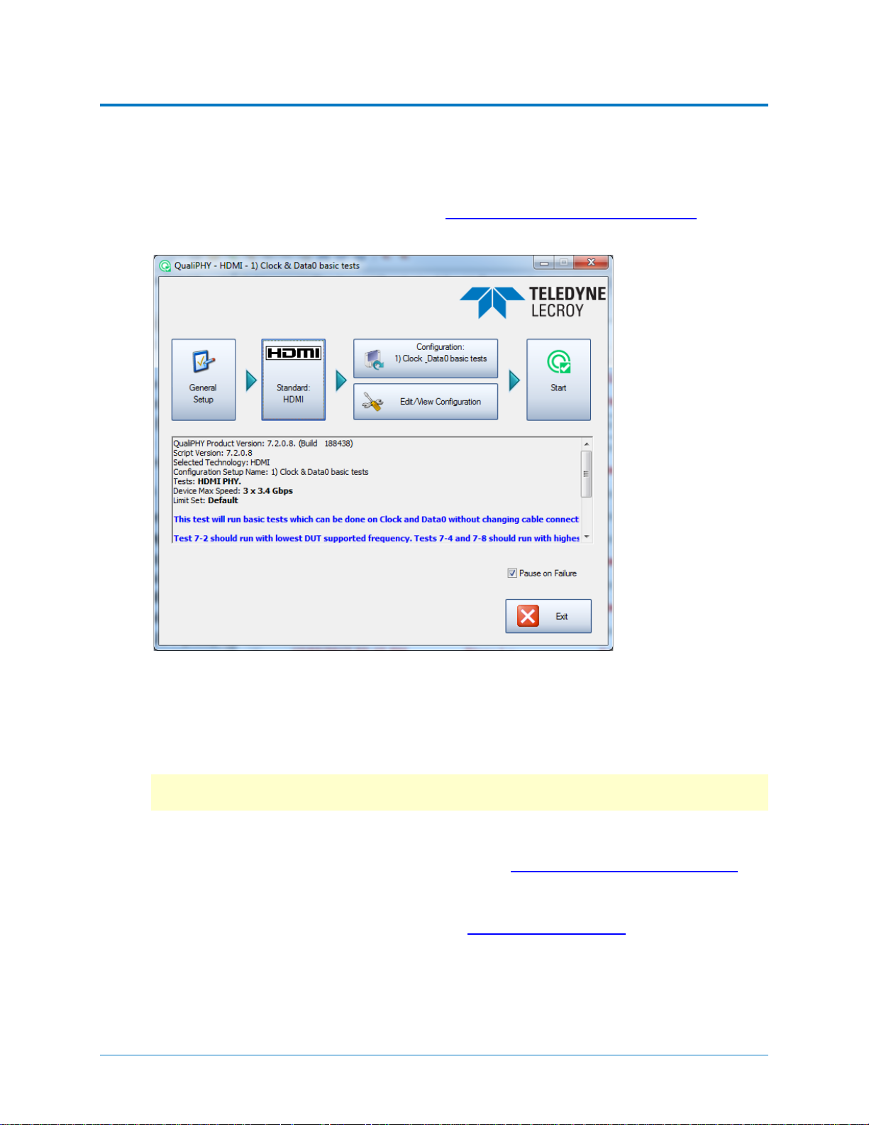
The QualiPHY framework dialog illustrates the overall software flow, from general set up
through running individual compliance tests. Work from left to right, making all desired settings
on each sub-dialog.
.
Figure 1 - QualiPHY framework dialog and Standard selection me nu.
The sub-dialogs are organized into tabs each containing configuration controls related to that
part of the process. These are described in more detail in the following sections.
If Pause on Failure is checked, QualiPHY prompts to retry a measure whenever a test fails.
Report Generator launches the manual report generator dialog.
The Exit button at the bottom of the framework dialog closes the QualiPHY application.
922540 Rev A 5
Page 10

General Setup
The first sub-dialog contains general system settings. These remain in effect for each session,
regardless of Standard, until changed.
Connection ta b
Shows IP Address of the test oscilloscope (local host 127.0.0.1 if QualiPHY is run from the
oscilloscope). The Scope Selector allows you to choose the oscilloscope used for testing when
several are connected to the QualiPHY installation. See Set Up Remote Control
Session Info tab
Optional information about the test session that may be added to reports, such as: Operator
Name, Device Under Test (DUT), Temperature (in °C) of the test location, and any additional
Comments. There is also an option to Append Results or Replace Results when continuing a
previous session.
To optimize report generation, enter at least a DUT name at the beginning of each session.
Report tab
Settings related to automatic report generation. Choose:
• Reporting behavior of:
for details.
o “Ask to generate a report after tests,” where you’ll be prompted to create a new
file for each set of test results.
o “Never generate a report after tests,” where you’ll need to manually execute the
Report Generator to create a report.
o “Always generate a report after tests,” to autogenerate a report of the latest test
results.
• Default report output type of XML, HTML, or PDF.
• A generic Output file name, including the full path to the report output folder.
Optionally, check Allow style sheet selection in Report Generator to enable the use of a
custom .css when generating reports. The path to the .css is entered on the Report Generator
dialog.
Report Generator launches the Report Generator dialog, which contains the same settings as
the Report tab, only applied to individual reports.
Advanced tab
This tab launches the X-Replay Mode dialog. See X-Replay Mode.
About tab
Information about your QualiPHY installation.
6 922540 Rev A
Page 11
QPHY-HDMI Operator’s Manual
QualiPHY Test Process
Once general system settings are in place, these are the steps for running test sessions.
Set Up Test Session
1. Connect the oscilloscope to the DUT. See QPHY-HDMI Testing Physical Setup.
2. Access the QualiPHY software to display the framework dialog.
3. If running QualiPHY remotely, click General Setup and open the Scope Selector to
select the correct oscilloscope connection.
4. If you have more than one component activated, click Standard and select the desired
standard to test against. Otherwise, your one activated component will appear as the
default selection.
Note: Although all the QualiPHY components appear on this dialog, only those selected
when installing QualiPHY are enabled for selection.
5. Click the Configuration button and select the test configuration to run. These preloaded configurations are set up to run all the tests required for compliance and provide
a quick, easy way to begin compliance testing. See QPHY-HDMI Test Configurations
a description of your configurations.
You can also create custom configurations for internal compliance tests by copying and
modifying the pre-loaded configurations. See Customizing QualiPHY
6. Close the Edit/View Configuration dialog to return to the framework dialog.
for de tails.
for
922540 Rev A 7
Page 12
Run Tests
1. On the framework dialog, click Start to begin testing.
When tests are in progress, this button changes to Stop. Click it at any time to stop the
test in process. You’ll be able to resume from the point of termination or from the
beginning of the test.
2. Follow the pop-up window prompts. QualiPHY guides you step-by-step through each of
the tests described in the standard specification, including diagrams of the connection to
the DUT for each required test mode.
3. When all tests are successfully completed, both progress bars on the framework dialog
are completely green and the message “All tests completed successfully” appears. If
problems are encountered, you’ll be offered options to:
• Retry the test from the latest established point defined in the script
• Ignore and Continue with the next test
• Abort Session
8 922540 Rev A
Page 13

QPHY-HDMI Operator’s Manual
Run Reports
The QualiPHY software automates report generation. On the framework dialog, go to General
Setup > Report to pre-configure reporting behavior. You can also manually launch the Report
Generator from the framework dialog once a test is run.
The Report Generator offers the same selections as the Report tab, only applied to each report
individually, rather than as a system setting. This enables you to save reports for each test
session, rather than overwrite the generic report file. There are also options to link a custom
style sheet (.xslt) to the report, or to Exclude Informative Results.
The Test Report includes a summary table with links to the detailed test result pages.
Figure 2 - The Test Report Summary Table and Detail page.
Reports are output to the base installation folder *\LeCroy\XReplay\Reports.
You can add your own logo to the report by replacing the file
*\LeCroy\XReplay\StyleSheets\CustomerLogo.jpg.
The recommended maximum size is 250x100 pixels at 72 ppi, 16.7 million colors, 24 bits. Use
the same file name and format.
922540 Rev A 9
Page 14

Customizing QualiPHY
The pre-loaded configurations cannot be modified. However, you can create your own test
configurations by copying one of the standard test configurations and modifying it.
Copy Configuration
1. Access the QualiPHY framework dialog and select a Standard.
2. Click Edit/View Configuration and select the configuration upon which to base the new
configuration. This can be a pre-loaded configuration or another copy.
3. Click Copy and enter a name and description. Once a custom configuration is defined, it
appears on the Configuration tab followed by “(Copy).”
4. Select the new, custom configuration and follow the procedures below to continue
making changes.
Note: If any part of a configuration is changed, the Save As button becomes active on
the bottom of the dialog. If a custom configuration is changed, the Save button will also
become active to apply the changes to the existing configuration.
Select Tests
On the Test Selector tab, select/deselect the tests that make up the configuration. Each test is
defined by the HDMI standard. A description of each test is displayed when it is selected.
To loop any of the tests in this configuration, select the test from the list, then choose to loop
indefinitely until stopped or enter the number of repetitions.
10 922540 Rev A
Page 15

QPHY-HDMI Operator’s Manual
Edit Variables
The Variable Setup tab contains a list of test variables. See QPHY-HDMI Variables for a
description of each.
To modify a variable:
1. Select the variable on the Var iable Setup tab, then click Edit Variable. (You can also
choose to Reset to Default at any time.)
2. The conditions of this variable appear on a pop-up. Choose the new condition to apply.
922540 Rev A 11
Page 16

Edit Test Limits
The Limits tab shows the Limit Set currently associated with the configuration. Any limit set can
be associated with a custom configuration by selecting it in this field.
The Limits Manager shows the settings for every test limit in a limit set. Those in the default set
are the limits defined by the standard.
To create a custom limit set:
1. On the Limits tab, click Limits Manager.
2. With the default set selected, click Copy Set and enter a name.
Note: You can also choose to copy and/or modify another custom set that has been
associated with this configuration.
3. Double click the limit to be modified, and in the pop-up enter the new values.
You can also Import Limits from a .csv file. Navigate to the f ile location after clicking the
button.
Tip: Likewise, Export Limits creates a .csv file from the current limit set. You may wish to
do this and copy it to format the input .csv file.
12 922540 Rev A
Page 17

QPHY-HDMI Operator’s Manual
X-Replay Mode
The X-Replay mode window is an advanced (“developer”) view of QualiPHY. The tree in the
upper-left frame enables you to navigate to processes in the HDMI test script, in case you need
to review the code, which appears in the upper-right frame.
Two other particularly useful features are:
• A list of recent test sessions in the lower-left frame. While you can only generate a
report of the current test session in the QualiPHY wizard, in X-Replay Mode you can
generate a report for any of these recent sessions. Select the session and choose
Report > Create Report from the menu bar.
• An event log is shownn the bottom-right frame. The frame can be split by dragging up
the lower edge. The bottom half of this frame now shows the raw Python output, which
can be useful if ever the script needs debugging.
Figure 3 – X-Replay Mode window.
922540 Rev A 13
Page 18

QPHY-HDMI Testing
Test Preparation
Before beginning any test or data acquisition, the oscilloscope should be warmed for at least 20
minutes.
Calibration is automatic under software control and no manual calibration is required. The
calibration will be run again if the temperature of the oscilloscope changes by more than a few
degrees.
Required Test Modes
The QPHY-HDMI script requires that you place the DUT (Device Under Test) in the required test
modes. The script will prompt you to do so before each specific test, but it is recommended that
you ensures the DUT is capable of being placed in the required test modes before beginning
testing.
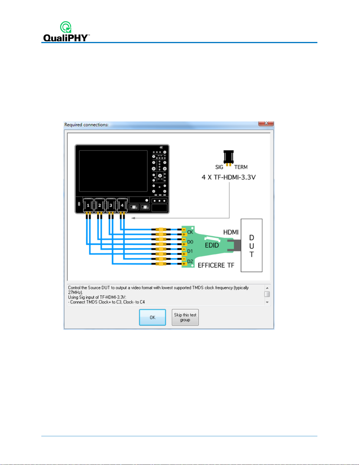
Physical Setup
The T el edyne LeCroy direct measurement solution uses SMA cables to connect two differential
signals at one time to the oscilloscope channels through the TF-HDMI-3.3V SIG input. SMA
cables are also used to terminate the unused signal onto specific TERM inputs.
See the description of each test configuration for specific set up information.
Deskew
HDMI signals are properly probed using two separate channels on the oscilloscope connected
to the appropriate SMA jacks on the test fixture. The highest measurement accuracy is achieved
when the timing skew between the two channels is calibrated.
The configurations will guide you through an initial deskew procedure. See the end of this
manual for two approaches to deskew. For optimal results, we recommend that you always first
deskew channels 2 and 3, then channels 1 and 2, followed by channels 3 and 4.
14 922540 Rev A
Page 19

QPHY-HDMI Operator’s Manual
QPHY-HDMI Test Configurations
Test configurations include variable settings, limit sets, and test selections. All ut ilize the Default
limit set. See QPHY-HDMI Variables
See the QPHY-HDMI Limit Sets for more information about the default test limits.
Clock and Data0 Basic Tests
This configuration runs all Clock and Data0 tests that can be run without changing cable.
Maximum device speed is 3 x 3.4 Gbps. Test 7-2 should run with lowest DUT supported
frequency . Tests 7-4 and 7-8 should run with highest DUT supported frequency.
These tests do not require the use of the “FindScale” variable to increase precision. Change the
variable “TMDS Data pair to test” to Data1 and Data2.
Clock and Data0 Tests at All Standard Frequencies
This configuration runs all Clock and Data0 tests that can be run without changing cable
connections at all frequencies. Maximum device speed is 3 x 3.4 Gbps. Tests 7-7 should run
with highest DUT supported frequency. Tests 7-9 and 7-10 are configured to run at all DUT
standard frequencies (27 MHz, 74.25 MHz, 148.5 MHz, and 222.75 MHz).
These tests require the use of the “FindScale” variable to increase precision. Change the
variable ‘TMDS Data pair to test” to Data1 and Data2.
for a description of each variable and its default value.
Data0 & Data1 & Data2 Inter-Pair Skew (7-6)
This configuration runs the Data Inter-Pair Skew (7-6) tests for all data lane combinations (D0D1, D0-D2, D1-D2). Maximum device speed is 3 x 3.4 Gbps. The tests require several cable
connections and disconnections. Test 7-6 should run with highest DUT supported frequency.
Clock and Data0 Tests at Cust om F re que nc y (340 MHz)
This configuration runs Clock Jitter and Eye Diagram tests (7-9 and 7-10) on Clock and Data0 at
a custom frequency (340 MHz). Maximum device speed is 3 x 3.4 Gbps. This combination is
useful when highest DUT supported frequency is not a standard frequency.
You can test other custom frequencies using the variable “DUT TMDS Clock Alternate
Frequencies” in groups 7-9 and 7-10. Change the variable “TMDS Data pair to test” to Data1
and Data2.
Demo of All Tests
This configuration runs all the tests in index order using stored waveforms in D:\HDMI\Demo
and the Default limit set. This configuration is meant to easily demonstrate the QPHY-HDMI
capabilities when live signals cannot be tested. You will see dialogs and connection diagrams
similar to what you would see during an actual test.
922540 Rev A 15
Page 20

QPHY-HDMI Test Descriptions
These are the standard HDMI compliance tests.
Test7-2: TMDS-VL
This test confirms that DC voltage levels on the HDMI link are within specified limits for each
TMDS signal.
R
EQUIREMENT
Single-ended, low level output voltage, VL:
If attached Sink supports only <=165MHz : (AVcc - 600mVolts) ≤ VL ≤ (AVcc - 400mVolts)
If attached Sink supports >165MHz : (AVcc - 700mVolts) ≤ VL ≤ (AVcc - 400mVolts)
Reference: [HDMI: Table 4-15] Source DC Characteristics at TP1
ETHODOLOGY
M
1. Connect TP A-P adapter to Source DUT HDMI output connector.
2. Connect TF-HDMI-3.3V to TMDS_DATA0+.
3. Configure the EDID to indicate only 27MHz formats (480p and 576p, no Deep Color
support) with the 640x480p Established Timings bit set.
4. Control the Source DUT to output a video format with lowest supported TMDS clock
frequency (typically 27MHz).
5. Capture 1000 or more repetitions, triggered at the vertical mid-point of the High-to-Low
transition of a H-L-L-L bit sequence. Each capture must be of duration 3*TBIT.
6. Display the voltage (vertical) histogram on the scope, with the histogram data
accumulated only from the last 2-bits of the H-L-L-L sequence.
7. Read the VL value as the most common low-level voltage shown on the histogram. If (VL
> 2.90V) OR (VL < 2.70V) then
8. Capture 10,000 repetitions, triggered at mid-point of waveform, of duration ≥ 2*TBIT to
get proper histograms.
9. Display the voltage (vertical) histogram on the scope. If (VL > 2.90V) OR (VL < 2.70V)
then FAIL
10. Repeat the test for all eight TMDS signals.
11. If CDF field Source_Above_165 , then switch to an EDID that additionally indicates:
a. Support for 1080p50Hz and 60Hz
b. Deep Color 36-bits/pixel
c. Max_TMDS_Clock of 225MHz (value = 225/5 = 45)
12. Repeat t est sequence above still using lowest clock rate format. If (VL > 2.90V) OR (VL
< 2.60V) then FAIL.
13. Repeat the test for all eight TMDS signals.
16 922540 Rev A
Page 21

QPHY-HDMI Operator’s Manual
Test7-4: TMDS TRise, TFall
This test confirms that the rise times and fall times on the TMDS differential signals fall within
the limits of the specification.
R
EQUIREMENT
75psec ≤ Rise Time or Fall Time
Reference: [HDMI: Table 4-16] Source AC Characte ristics at TP1
ETHODOLOGY
M
1. Connect TP A-P adapter to Source DUT HDMI output connector.
2. Configure Source DUT to output a video format and pixel size with highest supported
TMDS clock frequency .
3. Accumulate at least 10,000 triggered waveforms.
4. Measure TRISE as the mode of the sampled edge times from 20% to 80% of the
differential swing voltage rising edge.
5. Measure TF ALL as the mode of the sampled edge times from 80% to 20% of the
differential swing voltage on the falling edge.
If (TRISE < 75ps) then FAIL.
If (TFALL < 75ps) then FAIL.
6. Repeat the test for all remaining TMDS clock and data pairs.
Test7-5: TMDS Over/Undershoot
This test confirms that the differential TMDS signals do not have overshoot or undershoot
beyond that allowed by the specified limits (HDMI 1.0 only).
922540 Rev A 17
Page 22

Test7-6: TMDS Inter-Pair Skew
This test confirms that that any skew between the differential pairs in the TMDS portion of the
HDMI link does not exceed the limits in the specification.
R
EQUIREMENT
Inter-pair skew must not exceed 0.20*TPIXEL.
Reference: [HDMI: T able 4-16] Source AC Characteristics at TP1
ETHODOLOGY
M
1. Connect TP A-P adapter to Source DUT HDMI output connector.
2. Connect the first TF-HDMI-3.3V to TMDS_DATA0.
3. Connect the second TF-HDMI-3.3V to TMDS_DATA1.
4. Configure Source DUT to output an HDMI signal with a video format and pixel size with
highest supported TMDS clock frequency.
5. Capture (trigger) or find a sequence of Control Period encoded characters. Either 10-bit
or 20-bit trigger may be used. For 10-bit trigger:
6. Find the first bit of the TMDS character on the two TMDS channels. The CTL encoding
pattern 1101010100 corresponds to:
a. TMDS_DATA0: HSYNC=1, VSYNC=0
b. TMDS_DATA1: CTL0=1, CTL1=0 (any Preamble)
c. T MDS_DATA2: CTL2=1, CTL3=0 (Data Island Preamble)
If it is difficult to capture using the above patterns, then any of the following (Control
Period) patterns may be used:
a. 0010101011
b. 1101010100
c. 0010101010
d. 1101010101
7. Examine second channel for any valid CTL code and measure TIPSKEW between
channels.
8. For 20-bit trigger, find the first bit of the following 20-bit sequence on the TMDS
channels.
a. For Channel 0: 0010101011 0011001101
b. For Channel 0: 0010101010 0011001101
c. For Channel 0: 1101010101 0011001101
d. For Channel 1: 0010101010 1100110010
e. For Channel 2: 0010101011 0011001101
9. Examine second channel for the appropriate sequence and measure TIPSKEW between
channels. If TSKEW > 0.2*TCHARACTER then FAIL.
10. Repeat the test for remaining combinations of TMDS_DATAx pairs.
18 922540 Rev A
Page 23

QPHY-HDMI Operator’s Manual
Test7-7: TMDS Intra-Pair Skew
This test confirms that any skew within any one differential pair in the TMDS portion of the HDMI
link does not exceed the limits in the specification.
R
EQUIREMENT
Intra-pair skew between TMDS DATA pairs must not exceed 0.15*TBIT.
Reference: [HDMI: T able 4-16] Source AC Characteristics at TP1
ETHODOLOGY
M
1. Connect TP A-P adapter to the Source DUT HDMI output connector.
2. Connect the first TF-HDMI-3.3V to TMDS_DATA0+.
3. Connect the second TF-HDMI-3.3V to TMDS_DATA0-.
4. Configure Source DUT to output a video format and pixel size with highest supported
TMDS clock frequency.
5. Set the trigger on TMDS_DATA0+ rising edge.
6. Display the waveform of TMDS_DATA0+ and DATA0-. Accumulate 10,000 or more
triggers. Find the closest falling edge of DATA0- (either preceding or following DATA0+
rising edge) and determine the most common 50% crossing point of that TMDS_DATA0falling edge using a horizontal (time) Histogram method.
7. Measure skew from trigger point to most common 50% crossing point of TMDS_DATA0-.
If (skew > 0.15*TBIT) then FAIL.
8. Repeat the test for all remaining TMDS differential pairs.
922540 Rev A 19
Page 24

Test7-8: TMDS Clock Duty Cycle
This test confirms that the duty cycle of the differential TMDS clock does not exceed the limits
allowed by the specification.
R
EQUIREMENT
Clock duty cycle must be at least 40% and not more than 60%.
Reference: [HDMI: T able 4-16] Source AC Characteristics at TP1
ETHODOLOGY
M
1. Connect TP A-P adapter to Source DUT HDMI output connector.
2. Configure Source DUT to output a video format and pixel size with highest supported
TMDS clock frequency .
3. Connect TF-HDMI-3.3V to TMDS Clock.
4. Display the waveform of 1 clock period.
5. Configure the Digital Oscilloscope: trigger source is the TMDS Clock rising edge, turn on
infinite persistence, measurement is duty cycle, capture at least 10,000 or more triggers.
6. Measure minimum duty cycle as earliest crossing of TMDS_CLOCK falling edge. If
(TDUTY(MIN) < 40%, then FAIL.
7. Measure maximum duty cycle as latest crossing of TMDS_CLOCK falling edge.) If
(TDUTY(MAX) > 60%, then FAIL.
20 922540 Rev A
Page 25

QPHY-HDMI Operator’s Manual
Test7-9: TMDS Clock Jitter
This test confirms that the TMDS Clock does not carry excessive jitter.
R
EQUIREMENT
TMDS differential clock jitter must not exceed 0.25*TBIT, relative to the ideal Recovery Clock.
Reference: [HDMI: T able 4-16] Source AC Characteristics at TP1
EST METHODOLOGY
T
1. Connect TP A-P adapter to the Source DUT HDMI output connector.
2. Connect two TF-HDMI-3.3V test fixtures to each line of the TMDS Clock pair.
3. Configure oscilloscope and CRU: evaluate 16M samples per channel (can be acquired
with a single or with multiple smaller captures).
4. Configure Source DUT to output one video format for each of the following TMDS Clock
frequencies if that frequency is supported by the DUT: 27MHz (or 25MHz), 74.25MHz,
148.5MHz, and 222.75MHz. For each of these test frequencies, perform the following:
a. Capture the waveform and process it with the Digital Oscilloscope.
b. If test frequency is <=165MHz, then set Sampling Rate ≥10GSa/s
If test frequency is >165MHz, then set Sampling Rate ≥20GSa/s
c. Measure Clock jitter as difference between farthest left sampling point and
farthest right sampling point, at Vertical setting = VC = 0V ± 20mV. If Clock jitter
exceeds 0.25*TBIT then FAIL.
5. Repeat the test for remaining supported test frequencies. Only one video format/pixelsize combination is required per TMDS clock rate.
922540 Rev A 21
Page 26

Test7-10: TMDS Data Eye Diagram
This test confirms that the differential signal on each TMDS differential data pair has an “eye
opening” (region of valid data) that meets or exceeds the limits on eye opening in the
specification.
R
EQUIREMENT
Refer to the “Eye Diagram Mask at TP1 for Source Requirements.
Reference: [HDMI: Figure 4-18] Eye Diagram Mask at TP1
ETHODOLOGY
M
1. Connect TP A-P-TDR to Source DUT HDMI output connector.
2. Connect the first TF-HDMI-3.3V to TMDS Clock, and configure as trigger.
3. Connect the second TF-HDMI-3.3V to TMDS_DATA0.
4. Connect 50 ohm pull-ups to each of the non-probed TMDS lines to 3.3V.
5. Configure Source DUT to output one video format for each of the following TMDS Clock
frequencies if that frequency is supported by the DUT: 27MHz (or 25MHz), 74.25MHz,
148.5MHz, and 222.75MHz, and, if not already covered, the highest DUT-supported
frequency. For each of these test frequencies, perform the following.
6. Capture the waveforms on the Digital Oscilloscope. Process with the CRU to display the
data eye diagram.
a. Set memory length to 16M samples per-channel.
b. If test frequency is <=165MHz then set Sampling Rate ≥10GSa/s
If test frequency is >165MHz then set Sampling Rate ≥20GSa/s
7. Compare the data eye to the TP1 Eye Diagram Mask. If any part of the waveform
exceeds either the high or low maximum voltage (+/- 780mV), then FAIL.
8. Shift the mask left or right through one entire TBIT to determine if any horizontal position
has no capture points within eye mask. No vertical shifting is allowed. If no shifted
position exists where no part of the waveform touches or crosses into the data eye, then
FAIL.
9. Measure the data jitter at the zero crossing point. Measurement box vertical setting: 0V
±5mV. If data jitter > 0.3*TBIT then FAIL.
10. Repeat the test for remaining TMDS_DATA pairs.
11. Repeat the test for remaining supported test frequencies. Only one video format/pixelsize combination is required per TMDS clock rate.
22 922540 Rev A
Page 27

QPHY-HDMI Operator’s Manual
QPHY-HDMI Variables
EXECUTION ORDER MODE
Choose between CablingOrdered and IndeOrdered to define how the tests will be run. Currently
only IndexOrdered is available.
D
EMO MODE
Select demonstration mode. When enabled, previously stored HDMI waveforms will be used.
HDMI
VERSION TESTED
Select HDMI Compliance test version. There are two versions available: 1.4 and 1.3.
N
UMBER OF SWEEPS ACQUIRED FOR A MEASURE
Increase the number of sweeps to increase precision. Decrease for speed. Choose between 1,
5 or 10. Default is 10.
U
SER DEFINED SIGNAL VERTICAL GAIN
If set to default (or negative value), the script will initiate an automated find scale to determine
the gain and offset. If set to a positive value, it will be used to set the gain of all signals and the
"Re-use vertical settings" variable will be ignored. Default is 0.
U
SER DEFINED SIGNAL VERTICAL OFFSET
If variable is defined (> 0), this offset will be used for the signal and trigger levels.
R
E-USE VERTICAL SETTINGS
Enable re-use of memorized vertical settings (to speed up test). Choose between Yes and No.
Default is No (disabled) to ensure gain and offset are correctly set. This variable is ignored if
"User defined signal vertical gain" > 0.
S
AVE ACQUIRED WAVEFORMS
Saved waveforms can be used later in demonstration or optimized version of script. Choose
between Yes or No. Default is No. This setting is ignored (no save) if using stored waveforms is
enabled and in Demo mode.
S
ILENT MODE CONTROL
Turn on/off user interaction. Useful to let the test run repetitively in the background. Choose
between Yes or No. Default is No.
TMDS
DATA PAIR TO TEST
Define which Data Pair to test. Connect TMDS DATA + to C1 and DATA - to C2. Choose
between D0, D1, D2 or D1,D2,D3. The last option is the default and will test all Data Pairs.
U
SE STORED TRACE FOR PIXEL CLOCK MEASURE OPTIMIZATION
Use to measure the pixel clock frequency only once. Choose between Yes and No, Default is
No.
922540 Rev A 23
Page 28

WAVEFORM PATH
Specify the path on the oscilloscope to save/recall waveforms. When not in Demo Mode and
Save acquired waveforms is enabled, the waveforms will be saved in this folder. When set to
Demo Mode or Use stored trace for pixel clock measure, saved waveforms should be available
in this folder. Default is "D:\Waveforms\HDMI".
Specific to “Test7-2: TMDS-VL” Group
NUMBER OF SEGMENTS ACQUIRED IN SEQUENCE
HDMI specification requires 10'000 segments. For debugging only, r educe the number of
segments to speed-up processing. Choose between 10’000, 1000, 500 or 50. Default is 10’000.
R
ECALLED WAVEFORM FILE INDEX (5 DIGITS)
Enter the 5 digits number corresponding to the index of the file you want to recall. Default is
00000.
S
UPPORT OF TMDS FREQUENCY >= 165 MHZ
Choose between Yes or No. Default is No. If attached Sink device supports only <=165MHz,
limit is: (AVcc - 600mVolts) ≤ VL ≤ (AVcc - 400mVolts). If attached Sink device supports
>165MHz, limit is: (AVcc - 700mVolts) ≤ VL ≤ (AVcc - 400mVolts).
Specific to “Test7-4: TMDS TRise , TFal l” Grou p
RECALLED WAVEFORM FILE INDEX (5 DIGITS)
Enter the 5 digits number corresponding to the index of the file you want to recall. Default is
00000.
U
SE INTERNAL PEAK IF SIGNAL HAS TWO PEAKS
Default is No. Choose Yes to debug specific signal shape. HDMI signals can have two peaks in
amplitude. Classic measure of rise/fall time at 20-80% doesn't give stable results in this case.
So if two peaks are detected, we can use the internal one to determine rise/fall levels. But we
have observed signals with "faked" internal peaks. These additional peaks give inaccurate (too
short) rise/fall time. So disabling the use of internal peaks allows forcing usage of the highest
peaks.
Specific to “Test7-6: TMDS Inter -Pair Skew” Group
DATA-DATA TEST COMBINATIONS
Choose the combination of Data Pair to be tested between D0-D2 or D0-D1 or D2-D1 or D0D2,D0-D1,D2-D1. The last option is the default and will test all Data Pairs.
R
ECALLED WAVEFORM FILE INDEX (5 DIGITS)
Enter the 5 digits number corresponding to the index of the file you want to recall. Default is
00000.
24 922540 Rev A
Page 29

QPHY-HDMI Operator’s Manual
Specific to “Test7-7: TMDS I n tra-Pair Skew” Group
NUMBER OF SEGMENTS ACQUIRED IN SEQUENCE
HDMI specification requires 10'000 segments. For debugging only, r educe the number of
segments to speed-up processing. Choose between 10’000, 1000, 500 or 50. Default is 10’000.
Recalled Waveform File Index (5 digits)
Enter the 5 digits number corresponding to the index of the file you want to recall. Default is
00000.
Specific to “Test7-8: TMDS Clock Duty Cy cle” Group
NUMBER OF SEGMENTS ACQUIRED IN SEQUENCE
HDMI specification requires 10'000 segments. For debugging only, r educe the number of
segments to speed-up processing. Choose between 10’000, 1000, 500 or 50. Default is 10’000.
R
ECALLED WAVEFORM FILE INDEX (5 DIGITS)
Enter the 5 digits number corresponding to the index of the file you want to recall. Default is
00000.
Specific to “Test7-9: TMDS-Clock Jitter” Group
DUT TMDS CLOCK STANDARD FREQUENCIES
Configure Source DUT to output one video format for each of the following TMDS Clock
frequencies if that frequency is supported by the DUT: 27MHz (or 25MHz), 74.25MHz,
148.5MHz, 222.75MHz. Use DUT TMDS Clock Alternate Frequencies if the highest DUTsupported frequency is not in this list or if you wish to define custom frequencies.
DUT
TMDS CLOCK ALTERNATE FREQUENCIES
If different than 0, this value will be used as the maximum DUT TMDS Clock frequency in
addition to the standard frequencies selected. The frequency must be entered in scientific
format (e.g., 340 MHz as 340e6). You can enter a list of values using the “,” separator. Default
value is 0.
T
IMEBASE USED TO CREATE EYE DIAGRAM
Increase/decrease the number of points acquired to create Eye Diagram. 100us/div gives
enough samples to fulfill the 16 MS/Channel HDMI requirement.
R
ECALLED WAVEFORM FILE INDEX (5 DIGITS)
Enter the 5 digits number corresponding to the index of the file you want to recall. Default is
00000.
922540 Rev A 25
Page 30

Specific to “Test7-10: TMDS-Data Eye Diagram” Group
DUT TMDS CLOCK STANDARD FREQUENCIES
Configure Source DUT to output one video format for each of the following TMDS Clock
frequencies: 27MHz (or 25MHz), 74.25MHz, 148.5MHz, 222.75MHz and, if not already covered,
the highest DUT-supported frequency. Use alternate frequency if the highest DUT-supported
frequency is not already covered.
DUT
TMDS CLOCK ALTERNATE FREQUENCIES
If different than 0, this value will be used as the maximum DUT TMDS Clock frequency in
addition to the standard frequencies selected. The frequency must be entered in scientific
format, e.g. 340MHz as 340e6. The default value is 0.
R
ECALLED WAVEFORM FILE INDEX (5 DIGITS)
Enter the 5 digits number corresponding to the index of the file you want to recall. Default is
00000.
T
IMEBASE USED TO CREATE EYE DIAGRAM
Increase/decrease the number of points acquired to create Eye Diagram. 100us/div gives
enough samples to fulfill the 16 MS/Channel HDMI requirement.
QPHY-HDMI Limit Sets
The default installation of QPHY-HDMI contains only one limit set, called “HDMI_Default.” In
this script, limits are only used to convey Unit labels. The actual limits for each value tested are
encoded in or computed by the script and cannot be changed. The default limits used by QPHYHDMI are specified in version 1.4 of the High Definition Multimedia Interface Compliance Test
Specification (HDMI) .
26 922540 Rev A
Page 31

QPHY-HDMI Operator’s Manual
Manual Deske wing Procedures
This section is only applicable to the oscilloscope and the cables connecting to the oscilloscope
channels.
Cable Deskewing Using the Fast Edge Output
The following procedure demonstrates how to manually deskew two oscilloscope channels and
cables using the fast edge output, with no need for any T connector or adapters.
Note: Fast Edge output is available only on some models. If your oscilloscope does not have
Fast Edge output, see Cable Deskewing Using the DUT Signal.
This can be done once the temperature of the oscilloscope is stable. The oscilloscope must be
warmed up for at least a half-hour before proceeding. This procedure should be run again if the
temperature of the oscilloscope changes by more than a few degrees.
For the purpose of this procedure, the two channels being deskewed are referred to as Channel
X and Channel Y. The reference channel is Channel X and the channel being deskewed is
Channel Y.
1. Begin by recalling the Default Oscilloscope Setup.
2. Configure the oscilloscope as follows:
• Timebase
i. Fixed Sample Rate
ii. Set the Sample Rate to 40 GS/s
iii. Set the Time/Division to 1 ns/div
• Channels
i. Turn on Channel X and Channel Y.
ii. Set V/div for Channel X and Channel Y to 100mV/div.
iii. Set the Averaging of Channel X and Channel Y to 500 sweeps.
iv. Set the Interpolation of Channel X and Channel Y to Sinx/x.
922540 Rev A 27
Page 32

• Trigger
i. Configure to Source to be FastEdge.
ii. Set the Slope to Positive.
• Parameter Measurements:
i. Set the source for P1 to CX and the measure to Delay.
ii. Set the source for P2 to CY and the measure to Delay.
iii. Set the source for P3 to M1 and the measure to Delay.
3. Set the display to Single Grid.
• Click Display Single Grid.
4. Using the appropriate adapter, connect Channel X to the Fast Edge Output of the
oscilloscope.
5. Adjust the Trigger Delay so that the Channel X signal crosses at the center of the
screen.
6. Change the Timebase to 50 ps/div.
7. Fine tune the Trigger Delay so that the Channel X signal crosses at the exact center of
the screen.
8. Press the Clear Sweeps button on the front panel to reset the averaging.
9. Allow multiple acquisitions to occur until the waveform is stable on the screen.
28 922540 Rev A
Page 33

QPHY-HDMI Operator’s Manual
10. Save Channel X to M1.
• Click File Save Waveform.
• Set Save To Memory.
• Set the Source to CX.
• Set the Destination to M1.
• Click Save Now.
11. Disconnect Channel X from the Fast Edge Output and connect Channel Y to the Fast
Edge Output.
12. Press the Clear Sweeps button on the front panel to reset the averaging.
13. Allow multiple acquisitions to occur until the waveform is stable on the screen.
14. From the Channel Y menu, adjust the Deskew of Channel Y until Channel Y is directly
over the M1 trace.
15. Ensure that P3 and P2 are reasonably close to the same value. (Typically < 5ps
difference)
922540 Rev A 29
Page 34

Cable Deskewing Using the DUT Signal
This procedure does not require a Fast Edge output. Its other advantages are:
• It does not require adapters.
• You can de-skew at the same V/div settings you'll use to capture your data (because you
are capturing your data for this procedure).
• If the differential data signal has higher speed edges than the oscilloscope's AUX OUT, it
is easier to get good timing measurements with the faster edges. This is definitely the
case for HDMI.
Note: This procedure demonstrates how to deskew channels 2 and 3. For optimal results, this
method should be followed for channels 2 and 3, and then channels 1 and 2, followed by
channels 4 and 3 to insure that all channels are deskew appropriately.
1. Connect a differential data signal to C2 and C3 using two approximately matching
cables. Set up the oscilloscope as you plan to use it. Set the timebase to capture a few
repetitions of the compliance test pattern (at least a few dozen edges). Press Auto to
start acquisition.
2. On the C3 dialog, check Invert. Now C2 and C3 should look the same.
3. On the Measure dialog, set P1 to measure the Skew of C2, C3. Turn on Statistics.
Write down the mean skew value after it stabilizes. This mean skew value is the addition
of Data skew + cable skew + channel skew.
4. Swap the cable connections on the Data source side (on the test fixture), and then press
the Clear Sweeps button on the oscilloscope (to clear the accumulated statistics; since
we changed the input).
5. Write down the mean skew value after it stabilizes. This mean skew value is the addition
of (-Data skew) + cable skew + channel skew.
6. Add the two mean skew values and divide the sum in half:
The above formula simplifies to:
[cable skew + channel skew]
30 922540 Rev A
Page 35

QPHY-HDMI Operator’s Manual
7. Set the resulting value as the Deskew value in C2 menu.
8. Restore the cable connections to their Step 1 settings (previous). Press the Clear
Sweeps button on the oscilloscope. The mean skew value should be approximately zero
- that is the data skew. Typically, r esult s are <1ps given a test fixture meant to minimize
skew on the differential pair.
9. On the C3 dialog, un-check the Invert checkbox and turn off the parameters.
Now that the oscilloscope inter-channel skew and cable skew is compensated for, you
are ready to test.
The procedure as given above relies on the default setup of the Skew parameter (which is:
detecting positive edges on both signals, at 50%). C3 was inverted in order to make C2 and C3
both have positive edges at the same time. The default setup of any parameter is in effect at the
time it is set up.
Figure 4 - The Skew parameter right side dialog, Skew clock 2 tab, showing default setup.
922540 Rev A 31
Page 36

Error Messages
These messages may appear when using QualiPHY.
“Warning, no valid technology package has been found…” This message appears if none
of the QualiPHY components have been activated on the oscilloscope before launching the
QualiPHY application. See Activate Components.
“No devices connected to the application or device not alive…” This message appears if
you are running QualiPHY from a remote PC, but a) you have not connected any oscilloscopes
to the installation, or b) the oscilloscopes are offline. See Set Up Remote Control
oscilloscope.
“This test requires Firmware version x.x.x.x or higher.” The test oscilloscope firmware
needs to be updated. Go to teledynelecroy.com/support/softwaredownload under Oscilloscope
Downloads > Firmware Update to download the latest firmware.
“An <oscilloscope model> or better is required for <test>.” The test cannot be run with this
oscilloscope. If using remote control, you may be able to choose another connected
oscilloscope.
“This test requires the <name> option.” Besides installing the QualiPHY software, you must
purchase and activate the named software option on the oscilloscope.
to connect an
32 922540 Rev A
Page 37

 Loading...