

Page 1
QPHY-ENET
Ethernet Serial Data
Operator’s Manual
Revision G – October, 2008
Relating to the Following Release Versions:
• Software Option Rev. 5.7
• ENET Script Rev. 1.7
• Style Sheet Rev. 1.2
Page 2
LeCroy Corporation
700 Chestnut Ridge Road
Chestnut Ridge, NY 10977–6499
Tel: (845) 578 6020, Fax: (845) 578 5985
Internet: www.lecroy.com
© 2008 by LeCroy Corporation. All rights reserved.
LeCroy, ActiveDSO, WaveLink, JitterTrack, WavePro, WaveMaster, WaveSurfer, WaveExpert, WaveRunner and
WaveJet are registered trademarks of LeCroy Corporation. Other product or brand names are trademarks or
requested trademarks of their respective holders. Information in this publication supersedes all earlier versions.
Specifications subject to change without notice.
This electronic product is subject to
disposal and recycling regulations
that vary by country and region.
Manufactured under an ISO 9000
Registered Quality Management System
Visit Hwww.lecroy.comH to view the
certificate.
Many countries prohibit the
disposal of waste electronic
equipment in standard waste
receptacles.
For more information about proper
disposal and recycling of your
LeCroy product, please visit
www.lecroy.com/recycle.
Document Number: 915044 Rev G
2
QPHY-ENET Operator’s Manual Rev G
Page 3

QPHY-ENET Software Option
TABLE OF CONTENTS
INTRODUCTION ........................................................................................................................ 7
Compatibility ............................................................................................................................................................... 7
10Base-T, 100Base-TX and 1000Base-T .......................................................................................................... 7
10Base-T and 100Base-TX ................................................................................................................................ 7
Test Items ................................................................................................................................................................... 8
10Base-T [IEEE 802.3-2005] .............................................................................................................................. 8
100Base-TX [ANSI X3.263-1995] ....................................................................................................................... 8
1000Base-T [IEEE 802.3-2005] on pair A, B, C and D....................................................................................... 9
TF-ENET-B Test Fixture Package ............................................................................................................................ 10
Ethernet Test Fixture Sections ................................................................................................................................. 11
QualiPHY Compliance Test Platform ....................................................................................................................... 13
INSTALLATION ....................................................................................................................... 15
Oscilloscope Option Key Installation ........................................................................................................................ 15
Typical (Recommended) Configuration .................................................................................................................... 15
Remote (Network) Configuration ............................................................................................................................. 15
Oscilloscope Selection ............................................................................................................................................. 15
Connecting the oscilloscope to the Device Under Test (DUT) ................................................................................. 16
Accessing the QPHY-ENET Software using QualiPHY ........................................................................................... 16
Customizing QualiPHY ............................................................................................................................................. 18
QualiPHY-ENET Operation ...................................................................................................................................... 20
1000Base-T A, B, C or D Pair Selection .................................................................................................................. 21
OSCILLOSCOPE OPERATION .............................................................................................. 22
10Base-T Tests ........................................................................................................................................................ 24
Figure 13. Section A 10Base-T test area ......................................................................................................... 24
Table 2. 10Base-T section A jumper setting ..................................................................................................... 24
10Base-T DOV Mask and Voltage Test ........................................................................................................... 25
10Base-T TP_IDL Mask Test ........................................................................................................................... 28
10Base-T Link Test Pulse Mask ....................................................................................................................... 31
10-Base-T Output Timing Jitter ......................................................................................................................... 34
10Base-T Common Mode Output Voltage Test ............................................................................................... 37
100Base-TX Tests .................................................................................................................................................... 38
100Base-TX compliance test patterns .............................................................................................................. 39
100Base-TX Mask Test .................................................................................................................................... 41
100Base-TX Jitter Test ..................................................................................................................................... 42
100Base-TX Duty cycle distortion ..................................................................................................................... 43
100Base-TX Amplitude, Symmetry, and Overshoot ......................................................................................... 44
100Base-TX Rise and Fall Time ....................................................................................................................... 46
1000Base-T Measurements ..................................................................................................................................... 47
1000Base-T Peak Differential Voltage, Droop, Template - Mode 1 with Disturbing Signal ............................. 48
1000Base-T Transmitter Distortion - Mode 4 with Disturbing Signal ................................................................ 52
Mode 1 and Mode 4 without Disturbing Signal ................................................................................................. 54
1000BaseT jitter tests – with and without TX_TCLK ........................................................................................ 55
1000Base-T Master Jitter - Mode 2 without TX_TCLK ..................................................................................... 57
1000Base-T Slave Jitter - Mode 3 without TX_TCLK ....................................................................................... 58
1000Base-T Master and Slave Jitter - with TX_TCLK ...................................................................................... 59
1000Base-T Common Mode Output Voltage Test ........................................................................................... 66
TF-ENET-B JUMPER PIN CONFIGURATION GENERAL INFORMATION ............................ 67
Jumpers and Connectors .................................................................................................................................. 68
10BT w & w/o Twisted Pair Model section (A) .................................................................................................. 68
1000BT Jitter section (B) .................................................................................................................................. 68
Common Mode Output Voltage section (C) ...................................................................................................... 69
QPHY-ENET Operator’s Manual Rev G
3
Page 4

1000BT Template Tests section (D) ................................................................................................................. 69
Load & Probes section (F) ................................................................................................................................ 69
Differential Return Loss section (G) .................................................................................................................. 69
LINK PARTNER TESTING FOR 10BASE-T & 100BASE-TX DEVICES ................................ 70
TF-ENET-B TEST AND CALIBRATION PROCEDURES .......................................................... 72
Cable Deskewing ..................................................................................................................................................... 72
Signal Path Calibration Procedure ........................................................................................................................... 74
Disturber Calibration Procedure ............................................................................................................................... 77
Disturbing Signal Source .......................................................................................................................................... 78
Mode 1 Disturbing Signal .................................................................................................................................. 78
Mode 4 Disturbing Signal .................................................................................................................................. 78
Recommended Generator ................................................................................................................................ 78
FIGURES
Figure 1. TF-ENET-B test fixture package ........................................................................................................... 10
Figure 2. TF-ENET-B test fixture board sections ................................................................................................ 11
Figure 3. Report menu in QualiPHY General Setup ............................................................................................ 13
Figure 4. The Test Report includes a summary table with links to the detailed test results ......................... 14
Figure 5. QualiPHY main menu and compliance test Standard selection menu ............................................. 16
Figure 6. QualiPHY configuration selection menu ............................................................................................. 17
Figure 7. QualiPHY test item selection menu ...................................................................................................... 18
Figure 8. Variable Setup and Limits Manager windows ..................................................................................... 19
Figure 9. Start button ............................................................................................................................................. 20
Figure 10. Example of pop-up message box ....................................................................................................... 20
Figure 11. Example of pop-up connection diagram and dialog box ................................................................. 20
Figure 12. ENET Main Menu .................................................................................................................................. 22
Figure 13. Section A 10Base-T test area .............................................................................................................. 24
Figure 14. Fixture setup for 10Base-T mask test ................................................................................................ 25
Figure 15. 10Base-T DOV Mask Test .................................................................................................................... 26
Figure 16. DOV Peak Voltage Test ....................................................................................................................... 27
Figure 17. 10Base-T DOV Harmonics ................................................................................................................... 27
Figure 18. Fixture setup for TP_IDL test .............................................................................................................. 28
Figure 19. TP_IDL head mask test ........................................................................................................................ 29
Figure 20. TP_IDL tail mask test ........................................................................................................................... 30
Figure 21. Fixture setup for Link Pulse mask test .............................................................................................. 31
Figure 22. Link pulse mask test (head portion) .................................................................................................. 32
Figure 23. Link pulse mask test (tail portion) ...................................................................................................... 33
Figure 24. Fixture setup for jitter test .................................................................................................................. 34
Figure 25. Output Timing Jitter for 8BT ............................................................................................................... 35
Figure 26. Output Timing Jitter for 8.5BT ............................................................................................................ 36
Figure 27. Fixture setup for Common Mode Output Voltage ............................................................................. 37
Figure 28. Fixture setup for 100Base-TX mask test ........................................................................................... 39
Figure 29. Adjustment of vertical scale and coupling ........................................................................................ 40
Figure 30. 100Base-TX Mask Test ........................................................................................................................ 41
Figure 31. 100Base-TX Jitter Test ........................................................................................................................ 42
Figure 32. 100Base-TX duty cycle distortion ...................................................................................................... 43
4
QPHY-ENET Operator’s Manual Rev G
Page 5

QPHY-ENET Software Option
Figure 33. 100Base-TX differential output voltage and overshoot ................................................................... 45
Figure 34. 100Base-TX Rise and Fall Time .......................................................................................................... 46
Figure 35. Transmitter test signal in IEEE 802.3-2005 standard in clause 40.6 ............................................... 47
Figure 36. Fixture setup for Mode 1 and Mode 4 test with Disturbing Signal .................................................. 48
Figure 37. Block diagram of TF-ENET-B fixture section D ................................................................................ 49
Figure 38. 1000Base-T mode 1 test showing all masks ..................................................................................... 50
Figure 39. 1000Base-T mode 1 test showing one mask; all mask test results are listed in the menu ......... 51
Figure 40. 1000Base-T mode 1 test main menu .................................................................................................. 51
Figure 41. Setting the disturbing signal level for mode 1 test .......................................................................... 53
Figure 42. Mode 4 distortion measurement ......................................................................................................... 53
Figure 43. Fixture setup for Mode 1 and Mode 4 test without Disturbing Signal ............................................ 54
Figure 44. Menu setting for making the measurements without disturber present ........................................ 54
Figure 45. Mode 2 and Mode 3 w/o TX_TCLK w/o Link Partner ........................................................................ 56
Figure 46. Mode 2 and Mode 3 with TX_TCLK and Link Partner ....................................................................... 56
Figure 47. Mode 2 with TX_TCLK measuring Jtxout .......................................................................................... 60
Figure 48. Master Jitter with TX_TCLK and Link Partner ................................................................................... 60
Figure 49. Slave Jitter setup with TX_TCLK and Link Partner .......................................................................... 62
Figure 50. Example Slave with TX_TCLK Jitter display. .................................................................................... 63
Figure 51. Jitter test channel definition, this cable connects the Device Under Test to the Link Partner ... 65
Figure 52. Fixture setup for Common Mode Output Voltage ............................................................................. 66
Figure 53. TF-ENET-B test fixture board .............................................................................................................. 67
Figure 54. TF-ENET-B with jumpers and connections highlighted in yellow and labeled accordingly ........ 67
Figure 55. TF-ENET-B with connectors used for Link Partner testing ............................................................. 70
Figure 56. Example of setting the Ethernet Card on a Windows-Based PC to 10Mbps/Half Duplex Mode .. 70
Figure 57. The Skew parameter right side dialog, Skew clock 2 tab, showing default setup ........................ 73
Figure 58. Ethernet test menu for Differential Data connection confirmation ................................................. 74
Figure 59. TF-ENET-B fixture Disturbing Signal section block diagram .......................................................... 75
Figure 60. Data Amplitude measurement for Splitter calibration...................................................................... 76
Figure 61. Attenuated data measurement for Splitter calibration ..................................................................... 76
Figure 62. Disturbing Signal Amplitude measurement ...................................................................................... 77
TABLES
Table 1. Test Supported by TF-ENET-B Test Fixture ......................................................................................... 12
Table 2. 10Base-T section A jumper setting........................................................................................................ 24
Table 3. Pair and Jumpers configurations .......................................................................................................... 39
Table 4. Gigabit Ethernet tests, modes and fixtures .......................................................................................... 47
Table 5. Section D test pair jumper configurations ............................................................................................ 49
Table 6. Section G connector configuration and pair ........................................................................................ 54
Table 7. Mode 1 and 4 test Without Disturbing Signal ....................................................................................... 55
Table 8. Jitter Test Mode Limits ........................................................................................................................... 57
Table 9. Jumper configuration for each pair measurements (connection & termination) ............................. 69
QPHY-ENET Operator’s Manual Rev G
5
Page 6

6
QPHY-ENET Operator’s Manual Rev G
Page 7

QPHY-ENET Software Option
INTRODUCTION
QPHY-ENET is an automated test package that performs electrical tests for the three common networking
standards over unshielded twisted pair (UTP) cables normally referred to as CAT5 or CAT5E. The electrical tests
are performed on 10Base-T, 100Base-TX, and 1000Base-T signals as specified in the IEEE 802.3-2005 and
ANSI X3.263-1995 standards.
The QPHY-ENET option gives the user the ability to both automate compliance testing and debug devices, hosts
and hubs. Users may be specifically interested in the following capabilities:
• Users interested in compliance testing should begin by using QualiPHY.
• Users interested in debugging circuits, should begin by using the oscilloscope’s embedded test tools.
• Users that begin by using QualiPHY may detect failures on their device, and then have the option of
switching to the oscilloscope’s embedded test tools.
This manual covers the use of both QualiPHY (compliance testing) and the oscilloscope’s embedded test tools
(debugging).
The QualiPHY environment provides automated testing and report generation. For more information about
QualiPHY, see the QualiPHY Operator’s Manual (PDF document).
Compatibility
ENET is a software option compatible with the following LeCroy X-Stream™ oscilloscopes:
10Base-T, 100Base-TX and 1000Base-T
Oscilloscopes with a bandwidth of less than 1 GHz are not recommended for these standards.
Some tests requires at least 4 MS of memory in order to run (e.g. Mode 2 w/o clk Master Jitter on 1000Base-T).
• All WaveMaster series oscilloscopes
• All SDA series Serial Data Analyzer
• All DDA series Disk Drive Analyzer
• WavePro 7xxZi
• WavePro 7100, 7200, 7300, including “A” models
• WaveRunner 6100, 6200, including “A” models
• WaveRunner 104Xi, 204Xi, including "MXi" models
10Base-T and 100Base-TX
• WaveRunner 62Xi, 64Xi, 44Xi, including "MXi" models
• WaveRunner 6050 including “A” models
QPHY-ENET Operator’s Manual Rev G
7
Page 8

Test Items
10Base-T [IEEE 802.3-2005]
Peak Differential Output Voltage [14.3.1.2.1]
Differential Output Voltage Harmonics [14.3.1.2.1]
Template - Internal MAU (Normal & Inverted) [14.3.1.2.1]
Template - External MAU (Normal & Inverted) [14.3.1.2.1]
TP_IDL 100 Ω without TPM (Head & Tail) [14.3.1.2.1]
TP_IDL Load 1 without TPM (Head & Tail) [14.3.1.2.1]
TP_IDL Load 2 without TPM (Head & Tail) [14.3.1.2.1]
Link Pulse 100 Ω without TPM (Head & Tail) [14.3.1.2.1]
Link Pulse Load 1 without TPM (Head & Tail) [14.3.1.2.1]
Link Pulse Load 2 without TPM (Head & Tail) [14.3.1.2.1]
TP_IDL 100 Ω with TPM (Head & Tail) [14.3.1.2.1]
TP_IDL Load 1 with TPM (Head & Tail) [14.3.1.2.1]
TP_IDL Load 2 with TPM (Head & Tail) [14.3.1.2.1]
Link Pulse 100 Ω with TPM (Head & Tail) [14.3.1.2.1]
Link Pulse Load 1 with TPM (Head & Tail) [14.3.1.2.1]
Link Pulse Load 2 with TPM (Head & Tail) [14.3.1.2.1]
8BT Output Timing Jitter 100 Ω without TPM Internal MAU [14.3.1.2.3]
8.5BT Output Timing Jitter 100 Ω without TPM Internal MAU [14.3.1.2.3]
8BT Output Timing Jitter 100 Ω with TPM Internal MAU [14.3.1.2.3]
8.5BT Output Timing Jitter 100 Ω with TPM Internal MAU [14.3.1.2.3]
Common mode output voltage [14.3.1.2.5]
100Base-TX [ANSI X3.263-1995]
UTP DOV Base to Upper [ANSI 9.1.2.2]
UTP DOV Base to Lower [ANSI 9.1.2.2]
Overshoot Positive [ANSI 9.1.3]
Overshoot Negative [ANSI 9.1.3]
Signal Amplitude Symmetry [ANSI 9.1.4]
Rise Base to Upper [ANSI 9.1.6]
Fall Upper to Base [ANSI 9.1.6]
Rise Lower to Base [ANSI 9.1.6]
Fall Base to Lower [ANSI 9.1.6]
Rise/Fall Symmetry [ANSI 9.1.6]
Duty Cycle Distortion [ANSI 9.1.8]
Jitter Base to Upper [ANSI 9.1.9]
8
QPHY-ENET Operator’s Manual Rev G
Page 9

QPHY-ENET Software Option
Jitter Base to Lower [ANSI 9.1.9]
Twisted Pair Active Output Interface template [ANSI Appendix J]
1000Base-T [IEEE 802.3-2005] on pair A, B, C and D
Peak Differential Output Voltage point A, B, A vs. B, C, D [40.6.1.2.1]
Maximum Output Droop FG, HJ [40.6.1.2.2]
Template Mask point A, B, C, D, F, H [40.6.1.2.3]
Transmitter Distortion - Mode 4 [40.6.1.2.4]
Transmitter timing jitter Master (UnFiltered & Filtered) - Mode 2 [40.6.1.2.5]
Transmitter timing jitter Slave (UnFiltered & Filtered) - Mode 3 [40.6.1.2.5]
MDI common-mode output voltage [40.8.3.3]
QPHY-ENET Operator’s Manual Rev G
9
Page 10
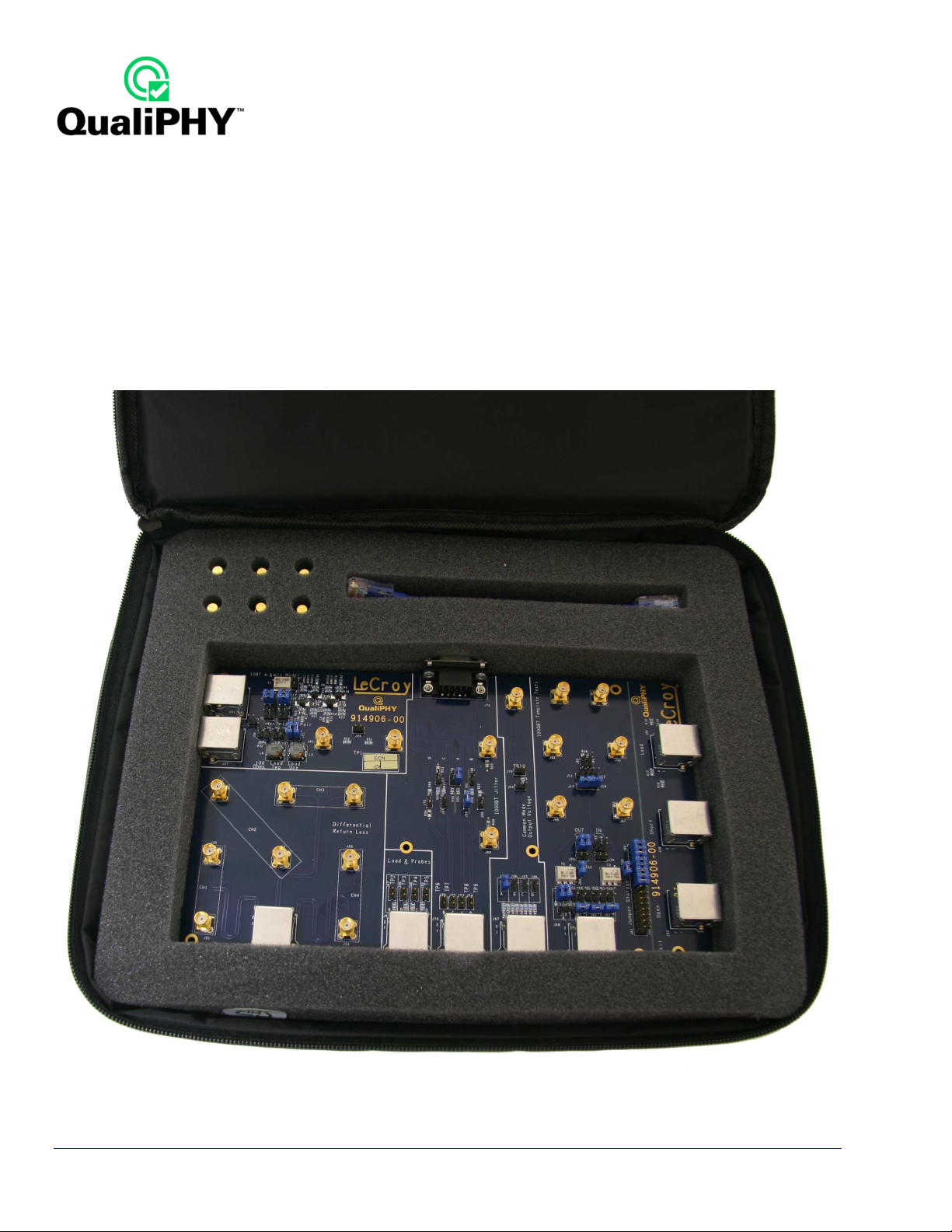
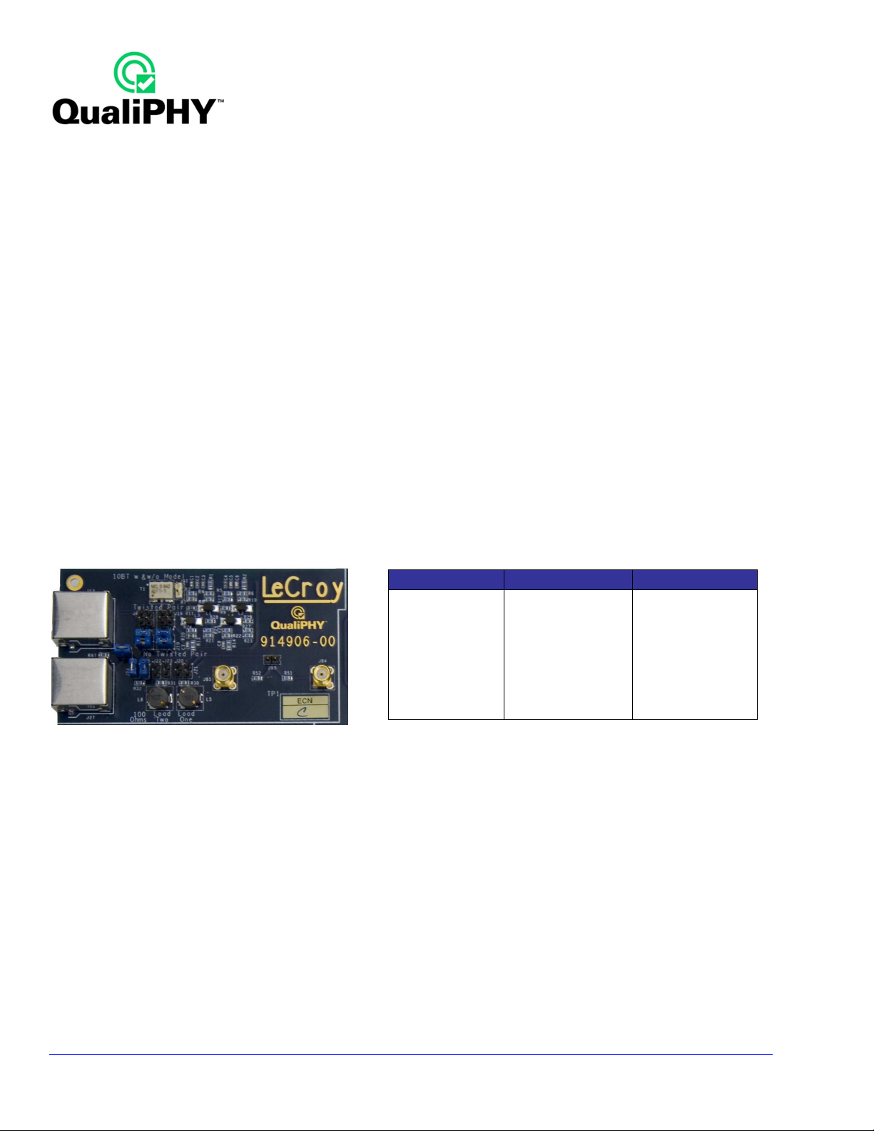
TF-ENET-B Test Fixture Package
The TF-ENET-B package is delivered in a soft pouch with a foam insert.
TF-ENET-B Standard supplied items include:
- Main Board
- 50 Ω Terminator (6)
- 6” RJ45 short cable (1)
- Jumpers (28)
- 18” SMA to SMA cables (2)
- BNC to SMA adapters (2)
10
Figure 1. TF-ENET-B test fixture package
QPHY-ENET Operator’s Manual Rev G
Page 11
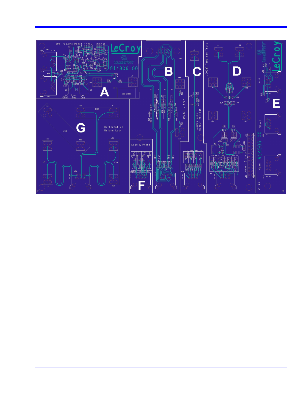
Ethernet Test Fixture Sections
QPHY-ENET Software Option
Figure 2. TF-ENET-B test fixture board sections
10BT w & w/o Model section (A)
1000Base-T Jitter section (B)
Common Mode Voltage Output section (C)
1000BT Template Disturbing Signal Tests section (D)
Return Loss Measurement section (E)
Jitter Master/Slave Test section (F) (for Differential Probe)
Differential Return Loss section (G)
QPHY-ENET Operator’s Manual Rev G
11
Page 12
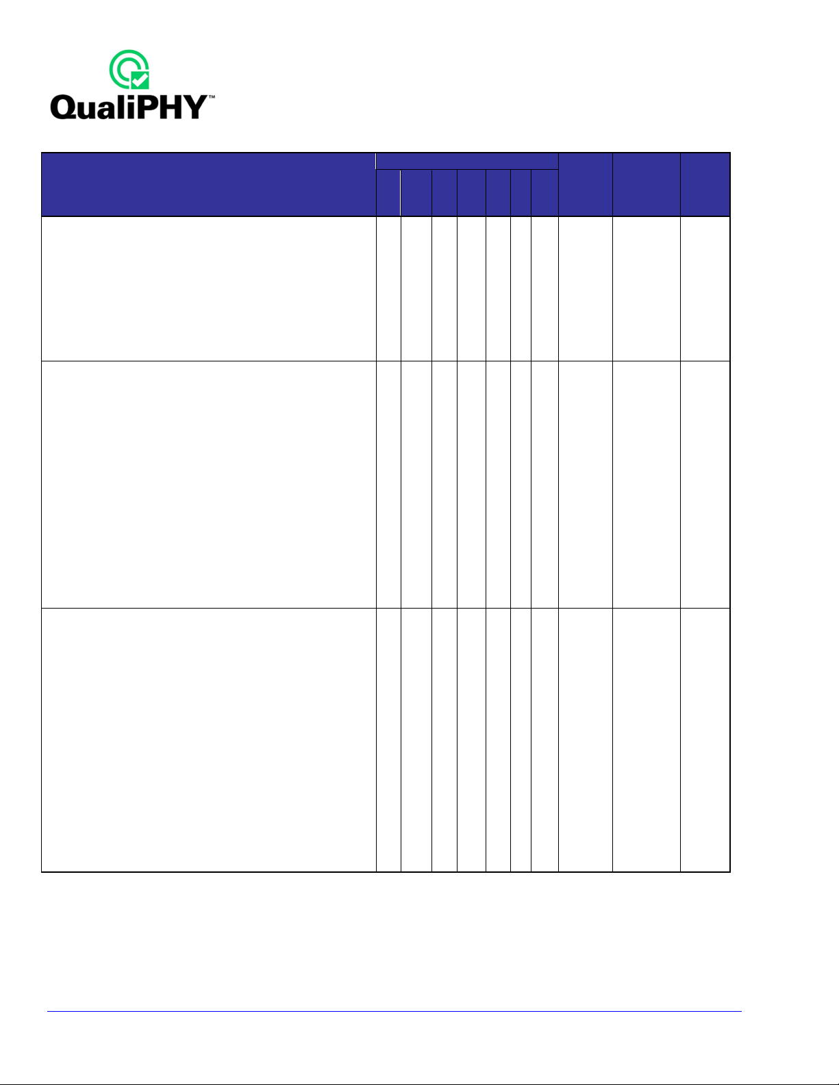
TEST ITEM
TF-
ENET
-B section
Jitter
A B C D E F G
1000BASE-T
MODE 1, 4 with Disturber
MODE 1, 4 without Disturber
MODE 2: MASTER JITTER with TX_TCLK
MODE 3: SLAVE JITTER with TX_TCLK
MODE 3: MASTER/SLAVE JITTER without TX_TCLK
COMMON MODE OUTPUT VOLTAGE
100BASE-TX
UTP DIFFERENTIAL OUTPUT VOLTAGE
OVERSHOOT
SIGNAL AMPLITUDE SYMMETRY
RISETIME BASE TO UPPER
FALLTIME UPPER TO BASE
RISETIME LOWER TO BASE
FALLTIME BASE TO LOWER
RISE/FALL TIME SYMMETRY
DUTY CYCLE DISTORTION
JITTER
TWISTED-PAIR ACTIVE OUTPUT INTERFACE TEMPLATE
10BASE-T
PEAK DIFFERENTIAL OUTPUT VOLTAGE
HARMONICS
INTERNAL/EXTERNAL MAU NORMAL
INTERNAL/EXTERNAL MAU INVERTED
100 Ω: TP_IDL & LINK PULSE*
LOAD 1: TP_IDL & LINK PULSE*
LOAD 2: TP_IDL & LINK PULSE*
OUTPUT TIMING JITTER*
8BT OUTPUT TIMING JITTER*
8.5BT OUTPUT TIMING JITTER*
COMMON MODE OUTPUT VOLTAGE
*WITH & WITHOUT TWISTED-PAIR MODEL
X X
X
X
X X X
X
X
X
X
X
X
X
X
X
X
X
X
X
X
X
X
X
X
X
X
X
X
X
X
Test
Cable
Link
Partner
AWG
12
Table 1. Test Supported by TF-ENET-B Test Fixture
QPHY-ENET Operator’s Manual Rev G
Page 13
QPHY-ENET Software Option
QualiPHY Compliance Test Platform
QualiPHY is LeCroy’s unique compliance test framework which leads the user through the compliance tests.
QualiPHY displays connection diagrams to ensure tests run properly, automates the oscilloscope setup, and
generates full compliance reports.
QPHY-ENET (DSO option) can be used without QualiPHY if each compliance test is executed manually.
However, QualiPHY makes QPHY-ENET easy and fast. QualiPHY is designed to use the TF-ENET-B test fixture
without using probes.
The LeCroy QPHY-ENET package displays all parameters for each measurement on the instrument screen along
with pass/fail indicators and the appropriate waveforms.
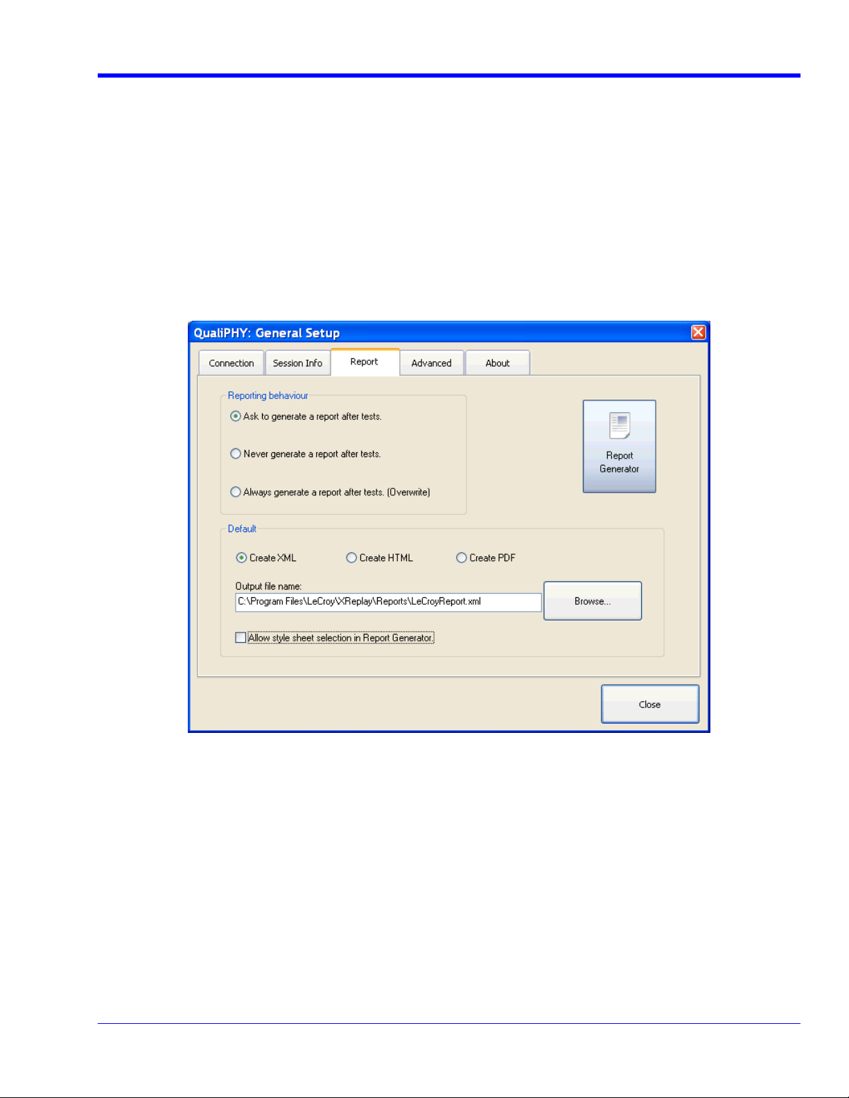
The QualiPHY software application automates the test and report generation.
QPHY-ENET Operator’s Manual Rev G
Figure 3. Report menu in QualiPHY General Setup
13
Page 14
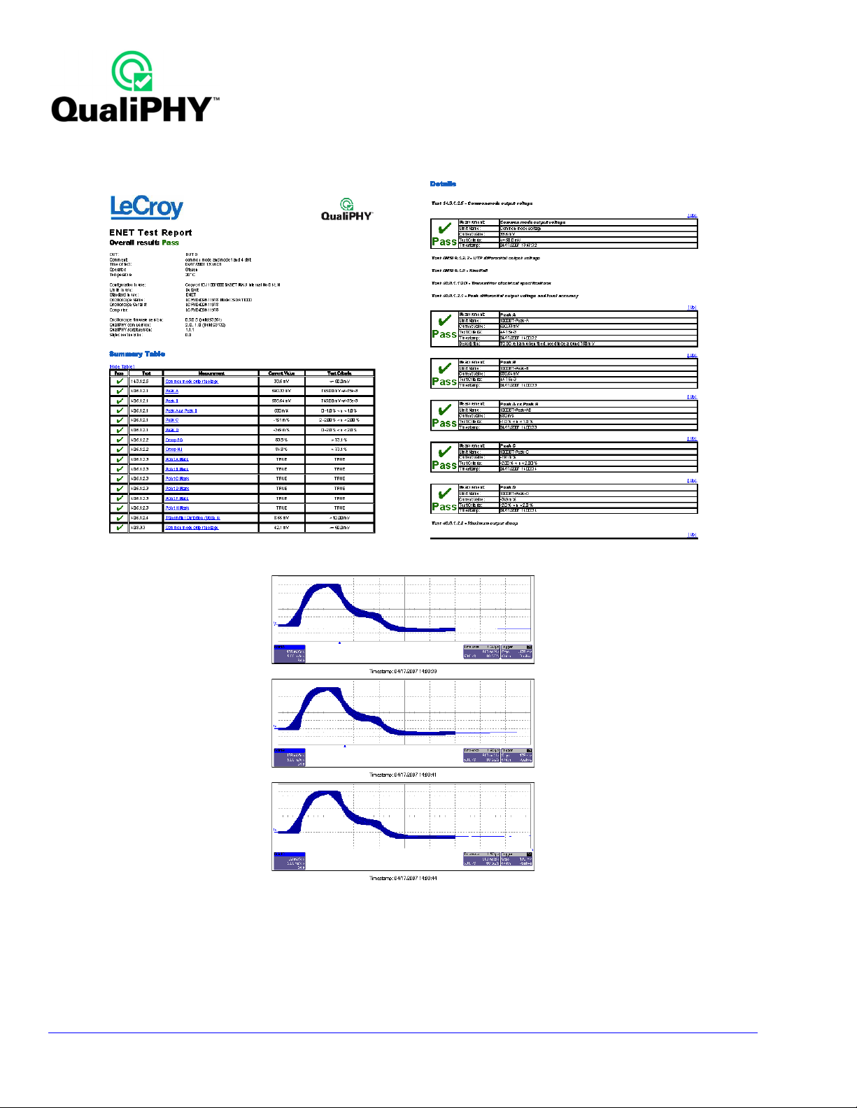
See the QualiPHY Operator’ s Manual for more information on how to use the QualiPHY framework.
Figure 4. The Test Report includes a summary table with links to the detailed test results
14
QPHY-ENET Operator’s Manual Rev G
Page 15

QPHY-ENET Software Option
INSTALLATION
Oscilloscope Option Key Installation
An option key must be purchased to enable the QPHY-ENET option. Call LeCroy Customer Support to place an
order and receive the code.
Enter the key and enable the purchased option as follows:
1. From the oscilloscope menu select Utilities Utilities Setup
2. Select the Options tab and click the Add Key button.
3. Enter the Key Code using the on-screen keyboard.
4. Restart the oscilloscope to activate the option after installation.
Typical (Recommended) Configuration
QualiPHY software can be executed from the oscilloscope or from a host computer. The first step is to install
QualiPHY, see the QualiPHY Operator’s Manual for installation instructions.
LeCroy recommends running QualiPHY on an oscilloscope equipped with Dual Monitor Display capability (Option
DMD-1 for oscilloscopes where this is not standard). This allows the waveform and measurements to be shown
on the oscilloscope LCD display while the QualiPHY application and test results are displayed on a second
monitor.
By default, the oscilloscope appears as a local host when QualiPHY is executed in the oscilloscope. Follow the
steps under XOscilloscope SelectionX (as follows) and check that the IP address is 127.0.0.1.
Remote (Network) Configuration
It is also possible to install and run QualiPHY on a host computer, controlling the oscilloscope with a Network/LAN
Connection.
The oscilloscope must already be configured, and an IP address (fixed or network-assigned) must already be
established.
Oscilloscope Selection
Set up the oscilloscope using QualiPHY over a LAN (Local Area Network) by doing the following:
1. Make sure the host computer is connected to the same LAN as the oscilloscope. If unsure, contact
your system administrator.
2. From the oscilloscope menu, select Utilities Utilities Setup
3. Select the Remote tab.
4. Verify the oscilloscope has an IP address and the control is set to TCP/IP.
5. Run QualiPHY in the host computer and click the General Setup button.
6. Select the Connection tab.
7. Enter the IP address from step 4 (previous).
8. Click the Close button.
QualiPHY is now ready to control the oscilloscope.
QPHY-ENET Operator’s Manual Rev G
15
Page 16
QualiPHY tests the oscilloscope connection after clicking the Start button. The system prompts you if there is a
connection problem. QualiPHY’s Scope Selector function can also be used to verify the connection. Please refer
to the QualiPHY Operator’s Manual for explanations on how to use Scope Selector and other QualiPHY
functions.
Connecting the oscilloscope to the Device Under Test (DUT)
The most accurate method of attaching the oscilloscope to the Device Under Test is by directly connecting the
fixture to the oscilloscope channels using a pair of SMA cables. The connections to the oscilloscope should be
made with good quality SMA cables of equal length. If the tests are being performed on a WavePro or
WaveRunner oscilloscope (which has only BNC connections) a SMA to BNC adaptor is required for each
channel. See the Cable Deskewing section of this manual for the calibration procedure.
Accessing the QPHY-ENET Software using QualiPHY
This section provides a basic overview of QualiPHY’s capabilities. Please refer to the QualiPHY Operator’s
Manual for detailed information.
Access the QPHY-ENET software using the following steps:
1. Wait for the oscilloscope to start and to have its main application running.
2. Launch QualiPHY from the Analysis menu if installed on the oscilloscope or,
3. Launch QualiPHY from the desktop icon if installed on a host computer.
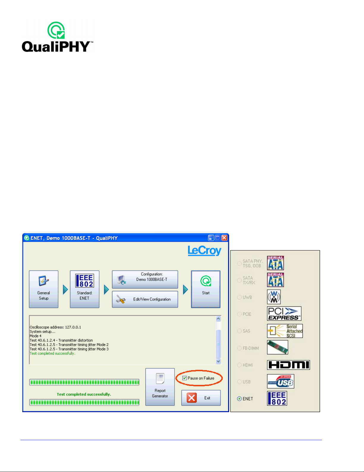
4. From the QualiPHY main window (as follows), select Standard, then ENET (IEEE 802) from the pop-up
menu (if not already selected). If you check the Pause on Failure box (circled) the system prompts to
retry the measure whenever it fails.
16
Figure 5. QualiPHY main menu and compliance test Standard selection menu
QPHY-ENET Operator’s Manual Rev G
Page 17
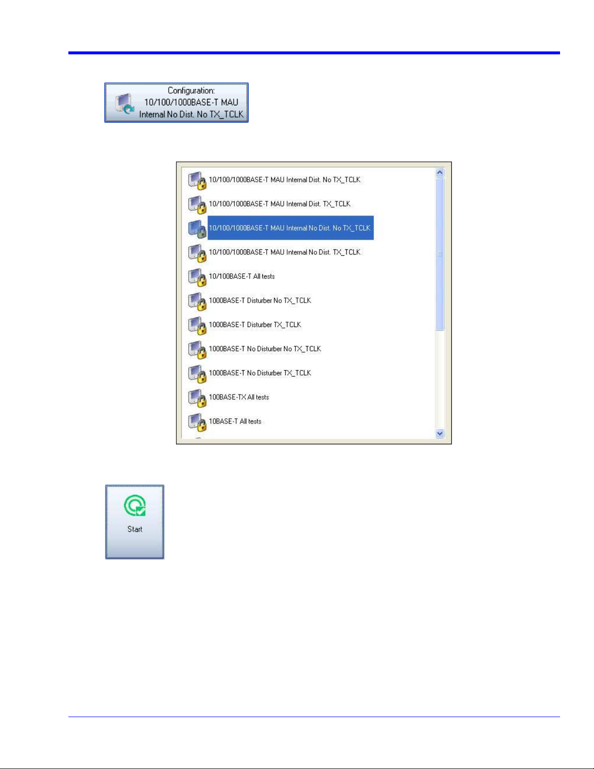
5. Click the Configuration button in the QualiPHY main menu:
6. Select a configuration from the pop-up menu:
QPHY-ENET Software Option
Figure 6. QualiPHY configuration selection menu
7. Click Start.
8. Follow the pop-up window prompts.
QPHY-ENET Operator’s Manual Rev G
17
Page 18
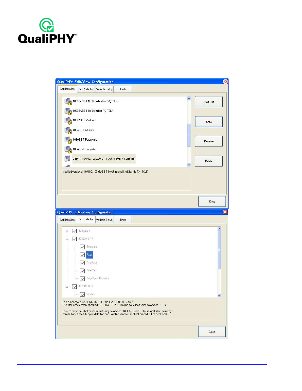
Customizing QualiPHY
The predefined configurations in the Configuration screen cannot be modified. However, you can create your
own test configurations by copying one of the standard test configurations and making modifications. A
description of the test is also shown in the description field when selected.
18
Figure 7. QualiPHY test item selection menu
QPHY-ENET Operator’s Manual Rev G
Page 19
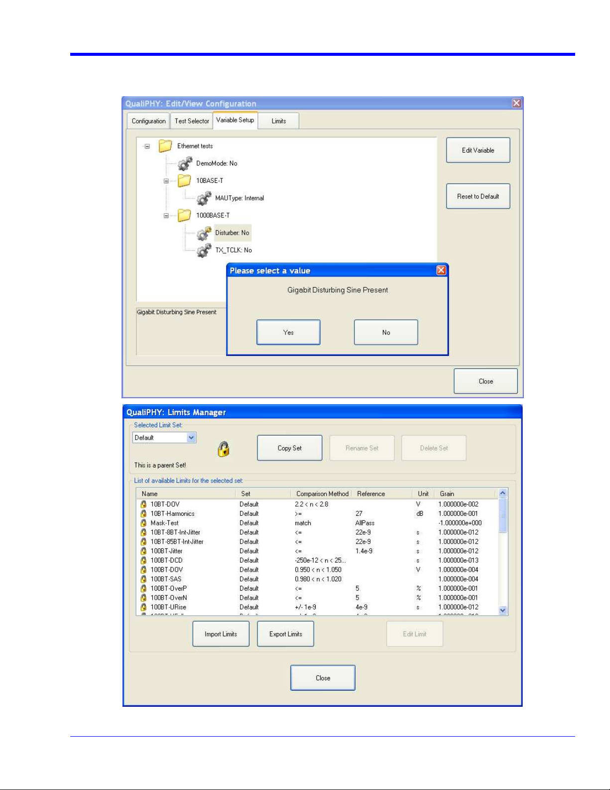
QPHY-ENET Software Option
Once a custom configuration is defined, script variables and the test limits can be changed by using the Variable
Setup and Limits Manager from the Edit/View Configuration window.
QPHY-ENET Operator’s Manual Rev G
Figure 8. Variable Setup and Limits Manager windows
19
Page 20
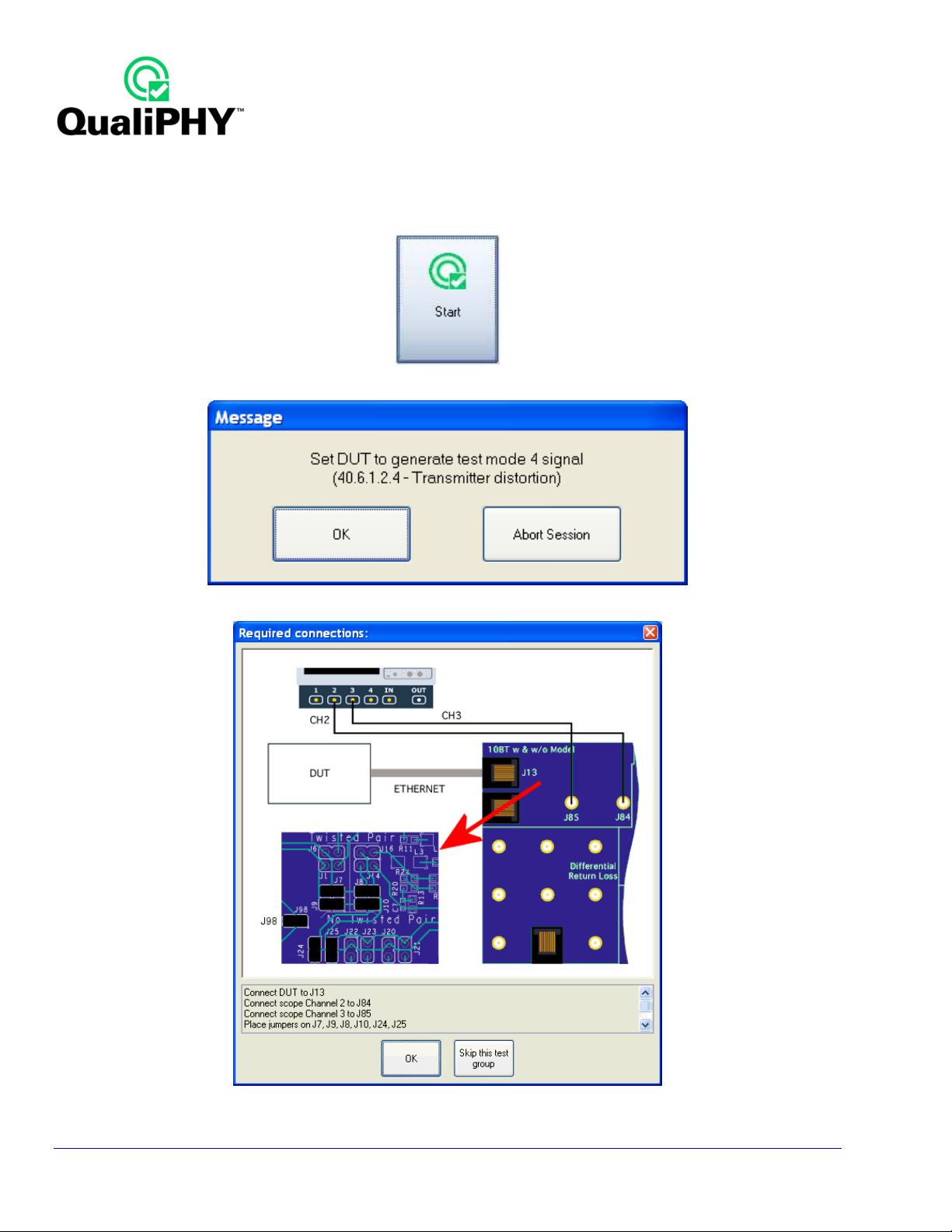
QualiPHY-ENET Operation
After pressing Start in the QualiPHY menu, a pop-up connection diagram and dialog box is shown to help set up
the test QualiPHY also instructs to change test signal mode (when necessary) with the QualiPHY pop-up
message box shown as follows.
Figure 9. Start button
Figure 10. Example of pop-up message box
20
Figure 11. Example of pop-up connection diagram and dialog box
QPHY-ENET Operator’s Manual Rev G
Page 21
QPHY-ENET Software Option
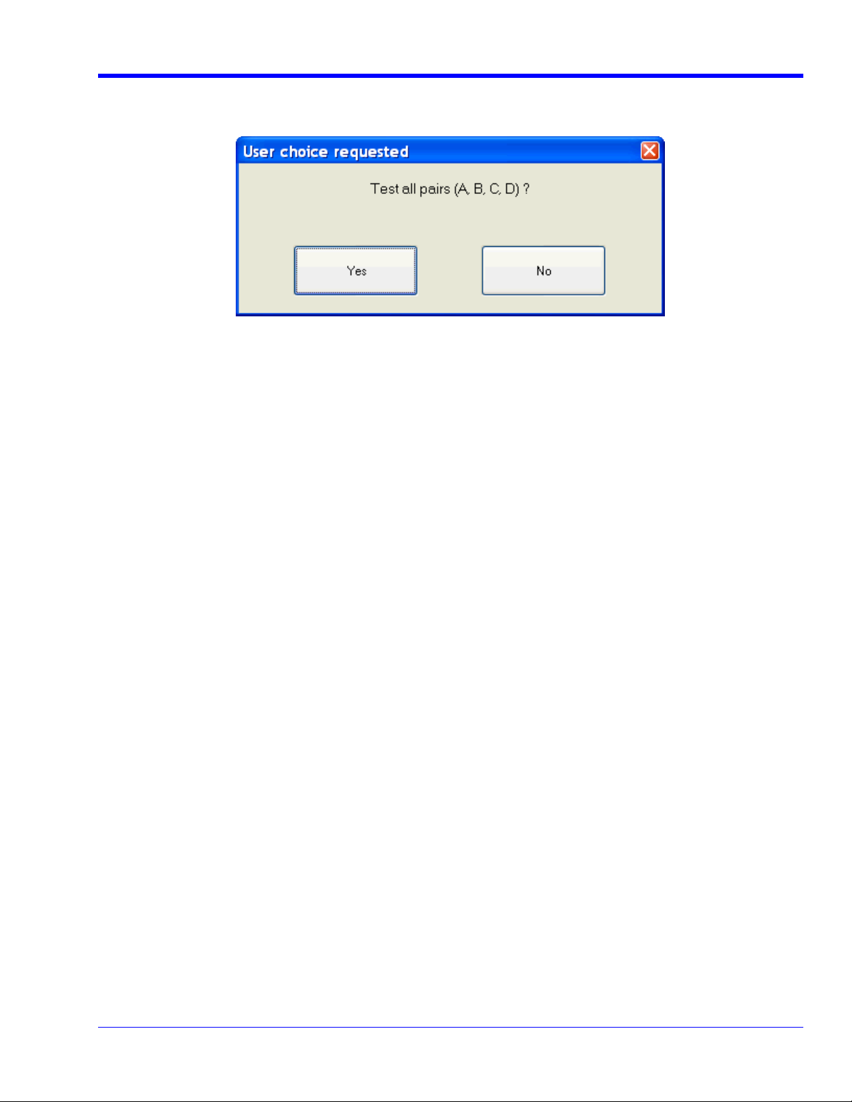
1000Base-T A, B, C or D Pair Selection
In the 1000Base-T test, a pop-up menu asks if the user is testing all 4 pairs of transmission lines.
If selecting No, the user is then prompted for each pair individually. This allows the user to only test the selected
pairs.
QPHY-ENET Operator’s Manual Rev G
21
Page 22
OSCILLOSCOPE OPERATION
This topic explains how to operate the oscilloscope manually. All of the following steps explained are automated
when using QualiPHY.
Although the oscilloscope settings can be changed at any time, it is not recommended to do so while a QualiPHY
script configuration is running. Doing so can modify the measurement and give erroneous report results.
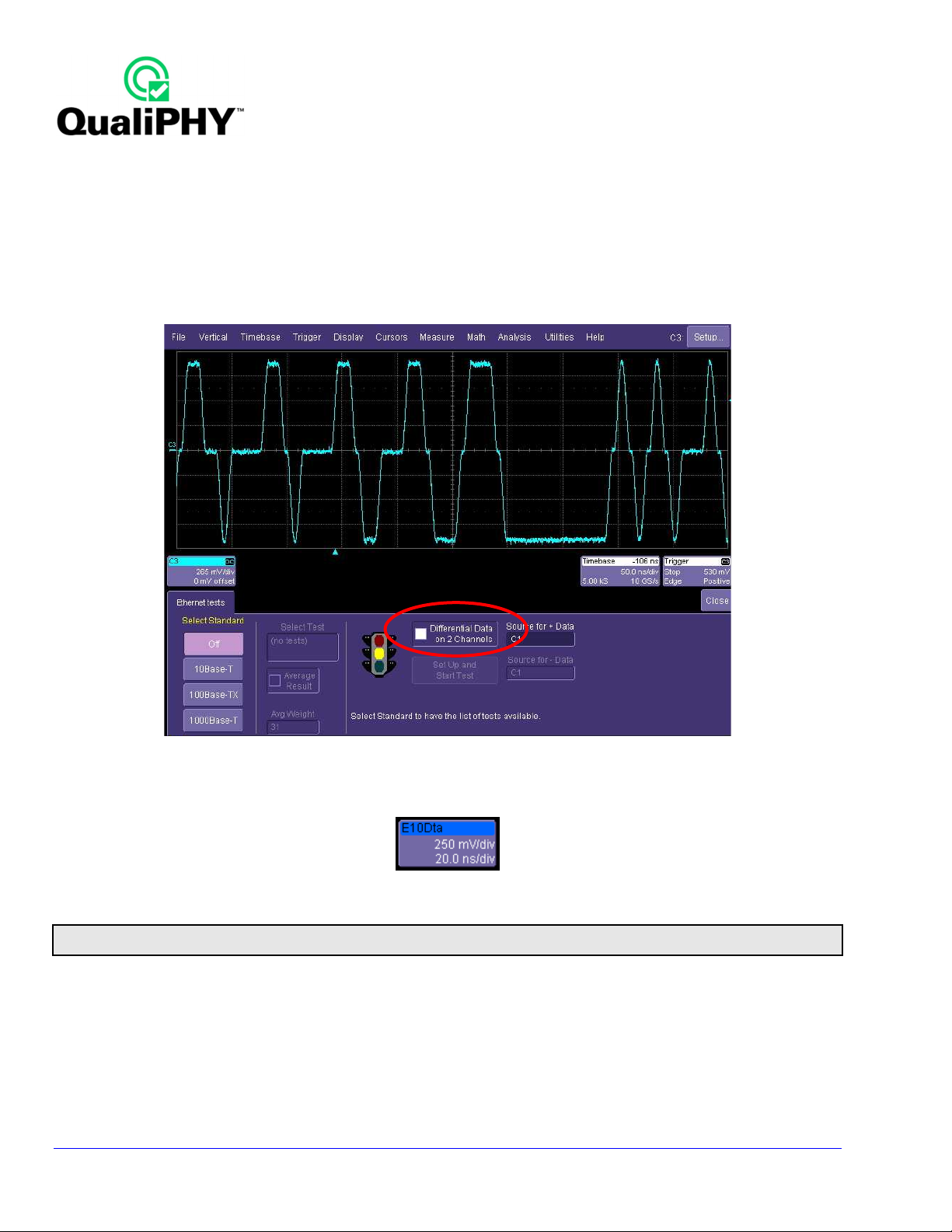
The main menu (pictured as follows) is shown at the bottom of the oscilloscope screen. The four buttons on the
left (10Base-T, 100Base-TX, 1000Base-T, and OFF) provide choices for the test standard.
Figure 12. ENET Main Menu
If the Ethernet Tests dialog is closed, it can be redisplayed in its most recent state by selecting Ethernet Tests
from the Analysis menu or by touching the ENET waveform descriptor label at the bottom-left of the screen:
The name in the title bar of the descriptor label indicates the measurement waveform. For the previous case, the
descriptor label is E10Dta.
Note: QualiPHY hides the dialog at the beginning of each script. This allows the best resolution for screen-shots to be incorporated on reports.
If the user chooses to redisplay the dialog, the screen–shots in the report are smaller.
22
QPHY-ENET Operator’s Manual Rev G
Page 23

QPHY-ENET Software Option
Source selection fields are displayed on the right side of the menu. The TF-ENET-B fixture is designed to use 2
SMA cables to ensure the best signal quality. The Differential Data on 2 Channels checkbox sets the
oscilloscope to use two channels to probe the differential pair.
Set C2 as Source for + Data and C3 as Source for - Data. Two controls for master TX_TCLK and slave
TX_TCLK are used for the 1000Base-T mode 2 and mode 3 jitter tests, and are grayed out otherwise.
When a differential probe is used, select the channel for the probe connection in the Source for + Data field.
The following topics describe the use of the ENET software option for testing 10Base-T, 100Base-TX, and
1000Base-T signal types.
QualiPHY automates most of the steps. Pop-up messages appear when specific actions must be done by the
user and a report is generated at the end of the compliance test.
QPHY-ENET Operator’s Manual Rev G
23
Page 24
10Base-T Tests
The required tests for the 10Base-T signal type are pulse mask, voltage level, and jitter. The requirements are
given in the IEEE 802.3-2005 standard (clause 14). The mask test requires the use of a “Twisted Pair Model,”
which effectively is a low-pass filter modeling the effect of transmitting the signal over a standard CAT5 cable.
This Twisted Pair Model is available in section A of TF-ENET-B from LeCroy.
Please refer to the test list in the 10 Base-T IEEE 802.3-2005 section of this manual.
Run the full set of 10Base-T tests by choosing the 10BASE-T All tests configuration in QualiPHY.
If the test needs to be done manually, use the following procedure:
1. From the menu bar, select Analysis Ethernet Tests
2. Touch the 10Base-T button on the left side of the menu to select the 10Base-T test mode.
The TF-ENET-B fixture allows for connecting each wire in the pair to a separate channel. Use the fixture section A
in the TF-ENET-B fixture set (XFigure 13X, as follows) to probe the signal using two channels. The test loads are
embedded in TF-ENET-B Fixture. Installing and removing Jumpers allows you to change test loads. (XTable 2X).
The 10Base-T transmitter is tested at the output of the Media Access Unit (MAU). This connection is made using
an RJ45 twisted pair connector. The MAU can be internal or external to the transmitter; and there are different
requirements for each type of MAU. The ENET software provides separate masks for each type of MAU to
accommodate these different requirements.
The 10Base-T test area of the TF-ENET-B also allows for devices to be tested using a link partner. See the Link
Partner Testing for 10Base-T & 100Base-TX section of this manual for more details.
Mode Install Jumper Remove Jumper
With TPM J1, J6, J14, J16 J7, J8, J9, J10
Without TPM J7, J8, J9, J10 J1, J6, J14, J16
100 Ω J24, J25 J20, J21, J22, J23
LOAD 1 J20, J21 J22, J23, J24, J25
LOAD 2 J22, J23 J20, J21, J24, J25
Figure 13. Section A 10Base-T test area Table 2. 10Base-T section A jumper setting
24
QPHY-ENET Operator’s Manual Rev G
Page 25

QPHY-ENET Software Option
10Base-T DOV Mask and Voltage Test
The differential output voltage (DOV) is defined as the absolute value of the peak differential voltage measured
into a 100 Ω termination. The mask test evaluates the pulse shape.
The transmitter should be set to generate a Pseudo Random bit pattern of at least 511 bits in duration. This
type of pattern will repeat every 511 bits or more so that over a shorter measurement time, the data will appear to
be random.
Note: The method for setting the Device Under Test into transmit mode is device specific. Contact your PHY chip vendor for information on
how to do this.
1. Connect DUT to J13 at section A of TF-ENET-B by using a short RJ45 cable included with TF-ENET-B
package. Remove jumpers J7, J8, J9, J10, J20, J21, J22, J23, and install jumpers J1, J6, J14, J16, J24,
J25, to test for TPM 100 Ω.
2. Connect oscilloscope channel 2 to J84, channel 3 to J85 (XFigure 14X, previous).
3. Touch the 10Base-T button under “Select Standard.”
4. Select the appropriate mask from the “Select Test” field:
• DOV Mask MAU Ext for external MAU testing
• DOV Mask MAU Ext Inv for external MAU testing of the negative-going pulses
• DOV Mask MAU Int for internal MAU testing
• DOV Mask MAU Int Inv for internal MAU testing of the negative-going pulses
Only two of the four masks above will be used for any given device (either internal or external MAU). Both
positive and negative-going pulses must be tested.
5. Check the Differential Data on 2 Channels checkbox to enable probing with two separate channels and
enter C2 in Source for + Data, C3 in Source for - Data field.
QPHY-ENET Operator’s Manual Rev G
Figure 14. Fixture setup for 10Base-T mask test
25
Page 26

6. Click the Set Up and Start Test button to start the test and display the pass/fail results.
7. Repeat the mask test for each of the test loads (100 Ω, LOAD1, and LOAD2) by changing jumpers setting
in Table 2, and for each pulse polarity (normal and inverted). There will be total 6 mask tests. Be sure to
touch the Set Up and Start Test button after each test is selected.
8. Remove jumpers J1, J6, J14, J16, and install jumpers J7, J8, J9, J10, to test without TPM.
9. Connect SMA cables from oscilloscope Channel 2 to fixture J84, Channel 3 to J85 (XFigure 14X).
10. Select DOV Peak in the “Select Test” field, then touch the Set Up and Start Test button. The screen will
change and the peak differential output voltage (DOV) will be measured. Parameter P1 indicates the peak
voltage, and Q1 and Q2 test the upper and lower limits of this value.
11. Select DOV Harmonics in the “Select Test” field, then touch the Set Up and Start Test button. The
display will show the Ethernet signal trace, and P1 will display the peak harmonic level in the power
spectrum of the signal. The Device Under Test should be transmitting an “all ones” pattern, which will be
coded as alternating positive and negative going pulses. This waveform will give the worst-case power
spectrum with the highest-level harmonics.
26
Figure 15. 10Base-T DOV Mask Test
QPHY-ENET Operator’s Manual Rev G
Page 27

QPHY-ENET Software Option
Figure 16. DOV Peak Voltage Test
QPHY-ENET Operator’s Manual Rev G
Figure 17. 10Base-T DOV Harmonics
27
Page 28

10Base-T TP_IDL Mask Test
This test measures the wave shape of the TP_IDL signal at the output of the MAU. This signal is sent over the
interface to indicate that the Device Under Test is ready to receive data. In this configuration, the TP_IDL signal is
an end-of-packet indicator. The TP_IDL begins with a positive transition and must remain at a positive voltage
level for between 2.5 and 4.5 bit times before going negative. Once the signal goes negative (below -50 mV) it
may not exceed +50 mV. The signal may not exceed +/- 50 mV after 45 bit periods. These requirements are built
into the masks in the measurement software.
The masks are broken into two parts: head and tail. The head mask includes the limits from the first transition out
to 20 bit intervals. The tail mask contains the requirements beyond 20 bit intervals. The mask test must pass for
two different test loads (LOAD1 and LOAD2) and is performed with and without the Twisted Pair Model. The
configuration provided in QualiPHY also test with 100 Ω load, although this is not required by the standard, it may
help debug faulty devices.
Figure 18. Fixture setup for TP_IDL test
1. Connect DUT to J13 and oscilloscope to the section A of TF-ENET-B as shown in XFigure 18X.
2. Install jumpers in this section to test for Twisted Pair Model (TPM) LOAD1. Refer to Table 2 (previous).
3. Set the DUT to transmit Pseudo Random data.
Note: The method for setting the Device Under Test into transmit mode is device specific. Contact your PHY chip vendor for information on
how to do this.
4. Touch the 10Base-T button under “Select Standard.”
5. Select TP_IDL Head Mask in the “Select Test” field. You should check the Average Result checkbox so
that the test is performed on an averaged waveform. Averaging reduces the noise in the trace.
6. Touch the Set Up and Start Test button to begin testing. The software will search for the TP_IDL pulse
and center it within the mask automatically.
28
QPHY-ENET Operator’s Manual Rev G
Page 29

QPHY-ENET Software Option
7. Select TP_IDL Tail Mask in the “Select Test” field.
8. Touch the Set Up and Start Test button to begin testing.
9. Install jumpers to test for TPM LOAD2; refer to Table 2 (previous).
10. Select TP_IDL Head Mask in the “Select Test” field.
11. Touch the Set Up and Start Test button to begin testing.
12. Select TP_IDL Tail Mask in the “Select Test” field.
13. Touch the Set Up and Start Test button to begin testing.
14. Install jumpers to test for no TPM LOAD1; refer to Table 2 (previous).
15. Select TP_IDL Head Mask in the “Select Test” field.
16. Touch the Set Up and Start Test button to begin testing.
17. Select TP_IDL Tail Mask in the “Select Test” field.
18. Touch the Set Up and Start Test button to begin testing.
19. Install jumpers to test without TPM LOAD2; refer to Table 2 (previous).
20. Select TP_IDL Head Mask in the “Select Test” field.
21. Touch the Set Up and Start Test button to begin testing.
22. Select TP_IDL Tail Mask in the “Select Test” field.
23. Touch the Set Up and Start Test button to begin testing.
QPHY-ENET Operator’s Manual Rev G
Figure 19. TP_IDL head mask test
29
Page 30

Figure 20. TP_IDL tail mask test
30
QPHY-ENET Operator’s Manual Rev G
Page 31

QPHY-ENET Software Option
10Base-T Link Test Pulse Mask
The link test pulse is a single-bit positive-going pulse that is transmitted by the MAU whenever it is active, and
before any traffic is present. This pulse is generated by a 10Base-T interface with no external connections. The
link test pulse mask is similar to the TP_IDL mask except for its duration. The mask test is performed using the
Twisted Pair Model jumpers setting in section A of TF-ENET-B (Table 2, Figure 19) and the test must pass for all
conditions. The mask test must pass for two different test loads (LOAD1 and LOAD2) and is performed with and
without the Twisted Pair Model. The configuration provided in QualiPHY also tests with a 100 Ω load. This is not
required by the standard, but it may help debug faulty devices.
Figure 21. Fixture setup for Link Pulse mask test
1. Connect DUT to J13 and oscilloscope to the SMA connector in the section A as shown in XFigure 21X.
Install jumpers to test with Twisted Pair Model (TPM) LOAD1. Refer to XTable 2X (previous).
2. Apply power to the Device Under Test. The link test pulse should appear on the oscilloscope screen.
3. Touch the 10Base-T button in the “Select Standard” field.
4. Select Link Test Pulse Head Mask in the “Select Test” field. You should check the Average Result
checkbox so that the test is performed on an averaged waveform. Averaging reduces the noise in the
trace.
5. Touch the Set Up and Start Test button to begin testing.
6. Select Link Test Pulse Tail Mask in the “Select Test” field.
7. Touch the Set Up and Start Test button to begin testing.
8. Install jumpers to test with TPM LOAD2. Refer to XTable 2X (previous).
9. Select Link Test Pulse Head Mask in the “Select Test” field.
10. Touch the Set Up and Start Test button to begin testing.
11. Select Link Test Pulse Tail Mask in the “Select Test” field.
12. Touch the Set Up and Start Test button to begin testing.
QPHY-ENET Operator’s Manual Rev G
31
Page 32

13. Install jumpers to test without TPM LOAD1. Refer to XTable 2X (previous).
14. Select Link Test Pulse Head Mask in the “Select Test” field.
15. Touch the Set Up and Start Test button to begin testing.
16. Select Link Test Pulse Tail Mask in the “Select Test” field.
17. Touch the Set Up and Start Test button to begin testing.
18. Install jumpers to test without TPM LOAD2. Refer to XTable 2X (previous).
19. Select Link Test Pulse Head Mask in the “Select Test” field.
20. Touch the Set Up and Start Test button to begin testing.
21. Select Link Test Pulse Tail Mask in the “Select Test” field.
22. Touch the Set Up and Start Test button to begin testing.
32
Figure 22. Link pulse mask test (head portion)
QPHY-ENET Operator’s Manual Rev G
Page 33

QPHY-ENET Software Option
Figure 23. Link pulse mask test (tail portion)
QPHY-ENET Operator’s Manual Rev G
33
Page 34

10-Base-T Output Timing Jitter
The timing jitter at the output of the MAU is determined by measuring the timing of the zero crossings at 8 bits and
8.5 bits from the triggering zero crossing. The jitter is measured and reported in parameter P1 below the grid on
the oscilloscope display.
A random bit stream from the device is used for this test, and two jitter measurements are made: one on the
transition at 8 bits from the trigger and the other at the transition at 8.5 bits from the trigger. The transitions
represent TD1 and TD0 values and are indicated in the user interface as 8 BT and 8.5 BT, respectively. In either
case (TD1 or TD0) the jitter, as indicated in parameter P1, shall be less than 22 ns for an internal MAU and 11 ns
for an external MAU. The output jitter is measured with and without the Twisted Pair Model and terminated into a
100 Ω resistive load.
Figure 24. Fixture setup for jitter test
1. Connect DUT to J13 at section A of TF-ENET-B by using a short RJ45 cable included with TF-ENET-B
package. Install jumpers for the test with TPM 100 Ω. Refer to XTable 2X (previous).
2. Connect oscilloscope channel 2 to J84, channel 3 to J85 (XFigure 24X).
3. Set the DUT to transmit Pseudo-Random bit stream.
Note: The DUT can be set to transmit random data by connecting the DUT to a Link Partner and transmitting a large file to the partner.
Please see the Link Partner Testing For 10BASE-T & 100BASE-TX Devices section of this manual for details on using a Link Partner.
4. Touch the 10Base-T button under “Select Standard.”
5. Select Output Timing Jitter 8 BT in the “Select Test” field.
6. Select external or integrated MAU as appropriate in the “MAU Type” field.
7. Touch the Set Up and Start Test button to begin testing.
8. The measurement displayed in P1 is the peak-to-peak value of the variation in the location of the
transition.
34
QPHY-ENET Operator’s Manual Rev G
Page 35

QPHY-ENET Software Option
9. Select Output Timing Jitter 8.5 BT in the “Select Test Field.”
10. Select external or integrated MAU as appropriate in the “MAU Type” field.
11. Touch the Set Up and Start Test button to begin testing.
12. The measurement displayed in P1 is the peak-to-peak value of the variation in the location of the
transition.
13. Install jumpers for the test without TPM 100 Ω. Refer to XTable 2X (previous).
14. Select external or integrated MAU as appropriate in the “MAU Type” field.
15. Touch the Set Up and Start Test button to begin testing.
16. The measurement displayed in P1 is the peak-to-peak value of the variation in the location of the
transition.
QPHY-ENET Operator’s Manual Rev G
Figure 25. Output Timing Jitter for 8BT
35
Page 36

Figure 26. Output Timing Jitter for 8.5BT
36
QPHY-ENET Operator’s Manual Rev G
Page 37

QPHY-ENET Software Option
10Base-T Common Mode Output Voltage Test
This test ensures that the zero to peak common mode output voltage at the MDI is within conformance limits. The
zero to peak common mode output voltage is measured as the worst-case minimum to worst-case maximum
common mode output voltage. This test does not use a high-pass filter. This measurement is made for pair A
only.
Figure 27. Fixture setup for Common Mode Output Voltage
1. Connect DUT to J67 and connect oscilloscope channel 2 to J2 as shown in XFigure 27X.
2. Measure pair A by setting jumper J35.
3. The common mode signal must be less than 50 mV to pass the test.
QPHY-ENET Operator’s Manual Rev G
37
Page 38

100Base-TX Tests
The 100Base-TX signal is an MLT-3 signal, that is, symbols are encoded into one of three voltage levels on the
twisted pair (+1, 0, and -1 V). The electrical requirements for this signal are defined in the ANSI X3.263-1995
standard for FDDI interfaces. The tests required by the standard are listed in the X100Base-TX [ANSI X3.263-
1995]X section (previous).
To run the full set of 100Base-TX tests, choose the 100BASE-TX All tests configuration in QualiPHY.
If the test needs to be run manually, use the following procedure:
1. From the menu bar, select Analysis Ethernet Tests
2. Touch the 100Base-TX button on the left side of the menu to select the 100Base-TX test mode.
The 10Base-T test area of the TF-ENET-B also allows for devices to be tested using a link partner. See the Link
Partner Testing for 10Base-T & 100Base-TX topic of this manual.
38
QPHY-ENET Operator’s Manual Rev G
Page 39

QPHY-ENET Software Option
100Base-TX compliance test patterns
100Base-TX testing requires special patterns that need to be generated from DUT port. DUT makers supply the
software to generate these testing patterns.
Figure 28. Fixture setup for 100Base-TX mask test
1. Connect the Device Under Test to the RJ45 jack J64 on the section G of TF-ENET-B using the short
cable supplied in the fixture kit.
2. Connect SMA cables to the oscilloscope for the pair you want to test using section G of the TF-ENET-B
test fixture. Refer to XTable 3.X.
Pair
Pair CH2
PairPair
A J51 J30
B J52 J31
C J32 J53
D J54 J33
Table 3. Pair and Jumpers configurations
3. Using the Vertical menu of the oscilloscope, set the coupling to “DC50Ω” and the offset to 0 V.
4. Set the Device Under Test to transmit a 100Base-TX Halt Line State (Jitter 9.1.9) signal.
Note: The test pattern needed depends on the test performed. Also, how to make a device generate the pattern is implementation specific.
Please consult your Ethernet PHY device manufacturer for information on setting the device to transmit the specific test patterns The ENET
software will also perform measurements on any arbitrary data pattern from the Device Under Test. Specific patterns are called out in this
procedure where they are required by the standard.
5. Adjust the level of the signal on channel 2 until it completely fills the grid on the oscilloscope screen
(about 7.5 divisions). Select “Variable Gain” in the Volts/Div control in the vertical menu. This provides
the maximum dynamic range to the measurement.
CH2 CH3
CH2CH2
CH3
CH3CH3
6. Set the vertical scale on channel 3 to the same value as that in channel 2 after the signal in channel 2 has
QPHY-ENET Operator’s Manual Rev G
39
Page 40

been set in previous step.
Figure 29. Adjustment of vertical scale and coupling
The signal should be adjusted using the Volts/div control to fill the grid. Note the green checkmark in the Variable
Gain control, which allows settings to be adjusted in 1 mV steps.
40
QPHY-ENET Operator’s Manual Rev G
Page 41

QPHY-ENET Software Option
100Base-TX Mask Test
Mask testing of 100Base-TX signals is a useful and quick method to determine the signal quality. While the 802.3
and ANSI specifications do not strictly require it, it is commonly used because a compliant signal will not have any
mask failures. More detailed analysis is required for compliance, however, because non-compliant signals may
not exhibit mask failures.
1. Set the Device Under Test to transmit the IDLE 100Base-TX data pattern. This pattern is transmitted by
the interface whenever there is no communication to a Link Partner.
2. Touch the 100Base-TX button under “Select Standard.”
3. Check Differential Data on 2 Channels.
4. Enter C2 in the Source for + Data field and C3 in the Source for - Data field (XFigure 30X).
5. Select Mask Test in the “Select Test” field.
6. Touch the Set Up and Start Test button to begin mask testing.
7. The position of the signal relative to the mask can be adjusted by the Alignment Adj. control if the mask
does not line up properly in the horizontal direction.
8. Q1 indicates the pass/fail condition, and a running count of the number of passed sweeps out of the total.
QPHY-ENET Operator’s Manual Rev G
Figure 30. 100Base-TX Mask Test
41
Page 42

100Base-TX Jitter Test
Jitter in 100Base-TX signals is defined as the time interval error between an ideal clock at the 125 MHz symbol
rate and the measured timing of the rising and falling edges of the positive and negative pulses. The reference
clock is recovered from the data signal under test using a numerical PLL computed from the threshold crossings
of the signal under test. The jitter test is performed on a scrambled IDLE stream. The IDLE stream is generated
by a 100Base-TX interface when it is terminated with no Link Partner.
1. Apply power to the Device Under Test. An MLT3 signal trace should be displayed on the oscilloscope
screen at this point.
2. Touch the 100Base-TX button under “Select Standard.”
3. Select Jitter in the “Select Test” field.
4. Check Differential Data on 2 Channels.
5. Enter C2 in the Source for + Data field and C3 in the Source for - Data field.
6. Touch the Set Up and Start Test button to begin testing.
7. P1 indicates the total jitter (peak-to-peak), and the number of passing sweeps (acquisitions) out of the
total.
8. The nominal bit rate is shown in the Base Frequency field. Click the Find Frequency field if the bit rate
is significantly different from 125 MHz or if the jitter number is excessively large.
9. The Average Result checkbox, when checked, averages the measured value of p-p jitter over the
number of acquisitions selected in the Avg Weight field.
Note: The results continue to be tested against the specified limit on each acquisition. The average is a moving window: for each acquisition
up to the specified weight, the average includes one additional measurement. After the weight count is reached, the oldest value is dropped
from the average and the latest measurement is added in.
42
Figure 31. 100Base-TX Jitter Test
QPHY-ENET Operator’s Manual Rev G
Page 43

QPHY-ENET Software Option
100Base-TX Duty cycle distortion
The duty cycle distortion measurement determines the timing error on four consecutive transitions of the
transmitter signal, consisting of consecutive positive and negative pulses. This MLT-3 code is generated by a
10101010 sequence. Duty cycle distortion is measured as the maximum deviation from the nominal 16 ns
spacing between all of the transitions at their 50% amplitudes.
1. Apply power to the Device Under Test. An MLT-3 signal trace should be displayed on the oscilloscope
screen at this point.
2. Set the Device Under Test to transmit a 1010... pattern.
3. Touch the 100Base-TX button under “Select Standard.”
4. Select Duty Cycle Distortion in the “Select Test” field.
5. Check Differential Data on 2 Channels.
6. Enter C2 in the Source for + Data field and C3 in the Source for - Data field.
7. Touch the Set Up and Start Test button to begin testing.
8. P1 indicates the duty cycle distortion and the number of passing sweeps (acquisitions) out of the total.
9. The Average Result checkbox, when checked, averages measurements over the number of sweeps
(acquisitions) specified in the Avg Weight field.
QPHY-ENET Operator’s Manual Rev G
Figure 32. 100Base-TX duty cycle distortion
43
Page 44

+
100Base-TX Amplitude, Symmetry, and Overshoot
The peak differential voltage of the MLT-3 signal should be +/-1 V, and the overshoot of transitions must be
limited to 5 %. Additionally, the symmetry between the positive and negative pulses must be within 2 % of each
other.
The overshoot value is measured by capturing the peak voltage at a transition from 0 V to 1 V (or 0 V to -1 V) and
comparing this level to the mean voltage of the signal when no transitions are occurring. The waveform for this
test must consist of a transition followed by 14 bit times during which the signal has no transitions.
The signal amplitude symmetry (SAS) is determined from the positive and negative peak voltage values using the
following equation:
||
out
98.0 ≤
V
≤
||
−
out
V
02.1
1. Apply power to the Device Under Test. An MLT3 signal trace should be displayed on the oscilloscope
screen at this point.
2. Set the Device Under Test to transmit the appropriate waveform, containing transitions between 0 V and
alternately +1 V and -1 V, with each state followed by 14 bit times during which no transition takes place.
3. Select 100Base-TX in the “Select Standard” field.
4. Select Amplitude Measurements in the “Select Test” field.
5. Check Differential Data on 2 Channels.
6. Enter C2 in the Source for + Data field and C3 in the Source for - Data field.
7. Touch the Set Up and Start Test button to begin testing.
8. Parameter P1 indicates the differential output voltage (DOV), P2 indicates the signal amplitude symmetry
(SAS), P3 indicates the overshoot for positive-going pulses, and P4 indicates the overshoot for negativegoing pulses.
9. The Average Result checkbox, when checked, averages measurements over the number of sweeps
(acquisitions) specified in the Avg Weight field.
PLEASE NOTE THE FOLLOWING:
• Maximizing the signal on the oscilloscope screen gives the best measurement results. Failure to adjust the signal to its highest level
may result in false failures being reported for the test.
• If you use a Random Pattern instead of the DCD (01010 NRZ bit) pattern, you may have a different test result.
44
QPHY-ENET Operator’s Manual Rev G
Page 45

QPHY-ENET Software Option
Figure 33. 100Base-TX differential output voltage and overshoot
QPHY-ENET Operator’s Manual Rev G
45
Page 46

100Base-TX Rise and Fall Time
The rise time of the MLT-3 signal is defined as the transition time from the baseline (0 V) to either the positive or
negative going peak, while the fall time is the time for the transition from either the positive or negative pulse to
the baseline. The times are measured from the 10 to 90 % levels. They are also measured for all transitions in the
waveform, and must be between 3 and 5 ns. In addition, all measured values for a given transmitter must be
within 0.5 ns of each other.
1. Apply power to the Device Under Test. An MLT3 signal trace should be displayed on the oscilloscope
screen at this point.
2. Select 100Base-TX in the “Select Standard” field.
3. Select Rise/Fall Measurements in the “Select Test” field.
4. Check Differential Data on 2 Channels.
5. Enter C2 in the Source for + Data field and C3 in the Source for - Data field.
6. Touch the Set Up and Start Test button to begin testing.
7. Parameters P1 through P7 display the results of this test. P1 and P2 give the rise and fall times for
positive-going pulses and P3 and P4 are the rise and fall times for negative-going pulses. Parameters P5
and P6 give the minimum and maximum rise/fall measurements and P7 gives the range between these
values.
8. The Average Result checkbox is grayed out in this mode, since averaging is not applicable to this
measurement.
46
Figure 34. 100Base-TX Rise and Fall Time
QPHY-ENET Operator’s Manual Rev G
Page 47

QPHY-ENET Software Option
1000Base-T Measurements
Transmitter measurements for gigabit Ethernet over copper (1000Base-T) are defined in the IEEE 802.3-2005
standard in clause 40.6. Four test modes are required in the physical layer device. A disturbing sine wave is
required for modes 1 and 4. The frequency and amplitude of this sine wave for each mode is listed in XTable 4X.
Section D of TF-ENET-B fixture is used for mode 1 and mode 4 tests with Disturbing Signal, section G is used for
the same tests without disturbing signal. Mode 2 and mode 3 tests are using section G of TF-ENET-B fixture.
Figure 35. Transmitter test signal in IEEE 802.3-2005 standard in clause 40.6
The tests required by the standard are listed in the X1000Base-T [IEEE 802.3-2005] on pair A, B, C and DX topic
on page X9X.
Table 4. Gigabit Ethernet tests, modes and fixtures
Test Test mode Fixture location Disturbing Sine Wave
w/Dist wo/Dist Frequency Amplitude
Peak differential output voltage
Maximum output droop
Differential output templates
Transmitter distortion
Jitter in master mode
Jitter in slave mode
Common Mode Output Voltage
1
1
1
4
2
3
4
D
D
D
D
G
G
C
G
G
G
G
31.25 MHz
31.25 MHz
31.25 MHz
20.833 MHz
N/A
N/A
N/A
2.8 V
2.8 V
2.8 V
5.4 V
p-p
p-p
p-p
p-p
N/A
N/A
N/A
These tests require calibration of the setup using TF-ENET-B, refer to the corresponding XSignal Path Calibration
ProcedureX topic on page X74X.
To run the full set of 1000Base-T tests, choose the 1000BASE-T All tests configuration in QualiPHY.
If the test needs to be run manually, use the following procedure:
1. From the menu bar, select Analysis Ethernet Tests
2. Touch the 1000Base-T button on the left side of the menu to select the 1000Base-T test mode.
QPHY-ENET Operator’s Manual Rev G
47
Page 48

1000Base-T Peak Differential Voltage, Droop, Template - Mode 1 with Disturbing Signal
This test is defined in 40.6.1.2.1 as: The absolute value of the peak of the waveform at point A and B, as defined
in XFigure 35X, shall fall within the range of 0.67V to 0.82 V (0.75 V +/-0.83 dB). These measurements are to be
made for each pair while operating in test mode 1 and observing the differential signal output at the MDI using the
transmitter test fixture with no intervening cable.
This test is performed on a physical interface transmitting the mode 1 waveform. Test section D is used to
perform the peak voltage and template tests. The disturbing sine wave is required for these tests. If you test mode
1 and 4 without disturbing sine wave, please refer to the XMode 1 and Mode 4 without Disturbing SignalX topic
on page X54X. When a disturbing signal is not used, the measurement should be made with the device terminated
into a 100 Ω resistive load. The difference of the peak absolute value at the points A and B should be less than
1 %. Ideally, the peak voltage at points C and D is 0.5 times the average of the peak voltage at points A and B.
The absolute value of the peak voltage at point C and D difference should be less than 2 % from the ideal voltage.
Note: The method for putting a particular PHY device into this and the other test modes required for 1000Base-T tests is unique to the
manufacturer. Contact the manufacturer of your PHY device for information on how to do this.
48
Figure 36. Fixture setup for Mode 1 and Mode 4 test with Disturbing Signal
QPHY-ENET Operator’s Manual Rev G
Page 49

QPHY-ENET Software Option
Figure 37. Block diagram of TF-ENET-B fixture section D
1. Calibrate data path (see the XSignal Path Calibration ProcedureX topic on page X74X).
2. Calibrate disturber sine wave (see the XDisturber Calibration ProcedureX topic on page X77X).
3. Connect AWG to J3 and J4.
4. Connect DUT to J68.
5. Install jumpers on J17/J19, J99/J100, J91/J92 and select Pair for your test.
Pair Install Remove
A J39, J40 J61, J60, J62
B J43, J44 J59, J60, J62
C J41, J42 J59, J61, J62
D J45, J46 J59, J61, J60
Table 5. Section D test pair jumper configurations
6. Transmit signal with disturbing sine wave should look like the picture shown in XFigure 41X. Select
1000Base-T under “Select Standard.”
7. Select Mode 1 Transmit Wform in the “Select Test” field.
8. Check Differential Data on 2 Channels box and enter C2 for Source for + Data and C3 for Source for
– Data.
9. Touch the Set Up and Start Test button to begin testing. The test automatically attempts to position each
pulse, so that it passes its template.
QPHY-ENET Operator’s Manual Rev G
49
Page 50

10. The Average Result checkbox is checked by default. Entering a number in the Avg Weight field causes
the selected number of waveforms to be averaged for each pulse (A, B, C, D, E and F).
Note: The templates used in this test have a very tight tolerance so even a small amount of noise in the measurement setup can cause mask
failures. It is recommended that averaging be used to reduce the measurement noise. The waveform looks distorted and may fail the mask
while the averaging accumulates.
11. Parameters P1 through P4 indicate the peak differential voltages at points A, B, C, and D. P5 indicates
the average absolute value of the peak voltages at A and B. P6 and P7 are the droop values.
12. The pass/fail qualifiers in Q1 through Q8 test the measurements against the standard requirements. The
criteria are listed below each qualifier. More detail on each of the criteria can be viewed by clicking on the
qualifier.
13. The Mask Tests tab shows the test results for the 6 masks defined by the standard. The Mask Tests
table lists the test result (OK/FAIL) for each mask. Clicking on any one of the tests in the list displays the
corresponding pulse with its compliance mask. A red circle highlights points where the curve touches the
mask.
14. Check the Show all Masks checkbox to view an octal grid displaying all of the mask tests on one screen.
The two grids on the top left of the display are reserved for the oscilloscope trace and the trace filtered by
the measurement filter (labeled EnetDta).
Note: The octal grid appears very small on the screen. Click the Close button at the top right of the menu to close it and expand the view. The
menu can be re-displayed by clicking on any one of the waveform descriptor boxes at the bottom left of the display or by selecting “Ethernet
tests” in the Analysis menu.
15. Repeat steps 9 through 14 for the other three pairs on the device by changing jumpers according to the
table in step 5.
50
Figure 38. 1000Base-T mode 1 test showing all masks
QPHY-ENET Operator’s Manual Rev G
Page 51

QPHY-ENET Software Option
Figure 39. 1000Base-T mode 1 test showing one mask; all mask test results are listed in the menu
QPHY-ENET Operator’s Manual Rev G
Figure 40. 1000Base-T mode 1 test main menu
51
Page 52

1000Base-T Transmitter Distortion - Mode 4 with Disturbing Signal
The distortion test measures the error in the signal under test relative to an ideal waveform generated by a
mathematical model of the PAM-5 coded signal. TF-ENET-B section D, which contains the disturbing signal, is
used for this test. The disturbing signal is set to a frequency of 20.833 MHz (125 MHz / 6) at a peak-to-peak
amplitude of 2.7 V at the input to the DUT. This is set using the Fixture Calibration procedure. The test requires
that the absolute maximum peak error be less than 10 mV.
The fixture used for this test allows the DUT to be subjected to the 2.7 V disturbing sine wave, but allows very
little of the disturbing sine wave to reach the oscilloscope. This allows the distortion measurement to be made on
an 8 bit oscilloscope. Due to the presence of the remnant of the disturbing sine wave, plus any noise, averaging is
required to be able to read <10 mV distortion. Our implementation averages Ethernet symbols in the vertical
domain only so that low-frequency wandering of the clock between acquisitions does not degrade the distortion
measurements. It takes a substantial number of sweeps for the “distortion” result to fall to below 10 mV and
remain stable; expect to average at least 100 sweeps. Clear sweeps clears this average. For automated test
support, the software sets a variable, which is available via automation, indicating when it believes the result
value, should be read. The variable is:
App.Ethernet.Dstr.GBM4ProducedGoodResult
This variable becomes set when the result is <8 mV after the first sweep, or is <9 mV after more than 30 sweeps
(this is the usual good case), or after 150 sweeps.
WARNING: The fixture requires the disturbing sine wave. Each side (0 degrees and 180 degrees) must
come from a 50 Ω source. If the disturbing sine wave is not present the BNC inputs must be terminated
with 50 Ω. Otherwise, reflections of the DUT’s signal from the un-terminated connections increase
distortion.
1. Calibrate data path (see the XSignal Path Calibration ProcedureX topic on page X74X).
2. Calibrate Disturber sine wave (see the XDisturber Calibration ProcedureX topic on page X77X).
3. Connect AWG to J3 and J4.
4. Connect DUT to J68.
5. Install jumpers on J17/J19, J99/J100, J91/J92 and select Pair for your test (refer to XTable 5. Section D test
pair jumper configurationsX).
6. Transmit signal with disturbing sine wave should look like the picture shown in XFigure 41X.
7. Set the Device Under Test to transmit the mode 4 waveform.
8. Adjust the Volts/div control in the Vertical menu to maximize the signal plus disturber on the oscilloscope
screen.
9. Select 1000Base-T under “Select Standard”.
10. Select Mode 4 Distortion in the “Select Test” field.
11. Enter the channels to which the SMA cables are connected: C2 for the Source for + Data field and C3 for the
Source for - Data field.
12. Click the Set Up and Start Test button to begin the test.
13. The initial distortion values may be above 30 mV but quickly drops as the averaging process proceeds. The
measurement reaches a minimum value and then varies around this level.
52
QPHY-ENET Operator’s Manual Rev G
Page 53

QPHY-ENET Software Option
Figure 41. Setting the disturbing signal level for mode 1 test
QPHY-ENET Operator’s Manual Rev G
Figure 42. Mode 4 distortion measurement
53
Page 54

Mode 1 and Mode 4 without Disturbing Signal
These tests are performed on a physical interface transmitting the mode 1 and mode 4 waveform. Test section G
is used to perform the peak voltage and template tests. When a disturbing signal is not used, the measurement
should be made with the device terminated by a 100 Ω resistive load. The test procedure is identical to
X
1000Base-T Peak Differential Voltage, Droop, Template - Mode 1 with Disturbing SignalX (page X48X) except
for not changing jumpers but changing a connection of SMA cable location in section G (XFigure 43X), when each
pair is measured, according to the table shown in XTable 6X. Mode 1 test uses Mode 1 signal and Mode 4 test uses
Mode 4 signal for the tests.
Pair CH2 CH3
A J51 J30
B J52 J31
C J32 J53
D J54 J33
Table 6. Section G connector configuration and pair
Figure 43. Fixture setup for Mode 1 and Mode 4 test without Disturbing Signal
1. On the oscilloscope’s Ethernet menu, Disturber present checkbox MUST be unchecked.
Figure 44. Menu setting for making the measurements without disturber present
54
QPHY-ENET Operator’s Manual Rev G
Page 55

QPHY-ENET Software Option
2. Use Differential Return Loss section of the board (G: recommended), for SMA cable connection (differential
probe can be used for section F).
3. Alternately, use the 1000BT template section as follows. Install jumpers on J77/J71 (the oscilloscope
connects to the DUT input signal) and install jumpers according to XTable 7X:
Pair Install Remove
A J39, J40 J61, J60, J62
B J43, J44 J59, J60, J62
C J41, J42 J59, J61, J62
D J45, J46 J59, J61, J60
Table 7. Mode 1 and 4 test Without Disturbing Signal
WARNING: Since J99 and J100 are not installed the input signal pair is not connected to the splitters. J77
and J71 connect the input signal pair to J86 and J87 (outputs to the oscilloscope) directly. So, this jumper
configuration makes this section of the board a straight through connection just like the Differential
Return Loss section of the board, but with multiple jumpers in the signal path.
Note: The Mode 1 and Mode 4 tests as defined in 802.3-2005 require the disturbing sine wave. Running the test without the
disturbing sine wave can be informative but it is not a required test.
1000BaseT jitter tests – with and without TX_TCLK
IEEE 802.3-2005 edition states at the end of section 40.6.1.1.3 (Test Fixtures): “Additionally, to allow for
measurement of transmitted jitter in master and slave modes, the PHY shall provide access to the 125MHz
symbol clock, TX_TCLK, that times the transmitted symbols The PHY shall provide a means to enable this
clock output if it is not normally enabled.” (Emphasis is ours.) This statement is reflected by two items in the
protocol implementation conformance statement (PICS) proforma for Clause 40, in 40.12.7 (PMA Electrical
Specifications), PME42 and PME43. The same text appeared in previous versions of the 802.3 specification back
to IEEE 802.3-2000.
Nonetheless it has become clear that most devices do not provide access to TX_TCLK in production models.
If your DUT does provide access to TX_TCLK please use the “Mode 2 Master Jitter” and “Mode 3 Slave Jitter”
1000BaseT tests. These follow the 802.3 standard.
If your DUT does not provide access to TX_TCLK, then use the “Mode 2 w/o clk Master Jitter” and “Mode 3 w/o
clk Slave Jitter” selections. They are discussed as follows.
The “w/o clk” jitter tests are based on “Appendix 40. B – Transmitter Timing Jitter, No TX_TCLK access”, version
1.1 dated March 25, 2002, which is part of the Gigabit Ethernet Consortium Clause 40 PMA Test Suite, version
2.4. The Gigabit Ethernet Consortium is based at the University of New Hampshire Interoperability Lab. This
document can be found at: HUftp://ftp.iol.unh.edu/pub/ethernet/test_suites/CL40_PMA/PMA_Test_Suite_v2.4.pdfU
This procedure was not proposed for inclusion in 802.3-2005, almost certainly because, as it says, “this procedure
deviates from the specifications outlined in Clause 40.6.1.2.5, it is not intended to serve as a legitimate substitute
for that clause, but rather as an informal test that may provide some useful insight” Nonetheless tests based on
this appendix have become the accepted way to measure jitter on devices that do not provide access to
TX_TCLK, as reflected in the GEC’s PMA Test Suite.
QPHY-ENET Operator’s Manual Rev G
55
Page 56

Figure 45. Mode 2 and Mode 3 w/o TX_TCLK w/o Link Partner
56
Figure 46. Mode 2 and Mode 3 with TX_TCLK and Link Partner
QPHY-ENET Operator’s Manual Rev G
Page 57

QPHY-ENET Software Option
1000Base-T Master Jitter - Mode 2 without TX_TCLK
Clause 40.6.1.2.5 of IEEE 802.3-2005 says to measure the jitter between the TX_TCLK and the data at the MDI
(Medium Dependent Interface) that is Jtxout - apply a 5 kHz high-pass filter to the TX_TCLK jitter, measure the
peak-to-peak remaining jitter, and add Jtxout, the result must be less than 0.3 ns. Also, the result of measuring
the peak-to-peak jitter on the TX_TCLK relative to an un-jittered reference must be less than 1.4 ns.
We can assume the Jtxout is small. So, it proposes the following measurements when TX_TCLK is unavailable:
the unfiltered peak-to-peak jitter at the MDI and the peak-to-peak remaining jitter when the unfiltered jitter is
filtered by a 5 kHz high-pass filter.
Since unfiltered jitter measured at the MDI is the sum of TX_TCLK jitter, plus Jtxout, if the result is less than
1.4 ns peak-to-peak then we can be sure that the TX_TCLK jitter is also less than 1.4 ns – in this case we can say
that this measurement “passes.” Keep in mind, this test is more difficult to pass than the test of unfiltered jitter on
TX_TCLK test specified in IEEE 802.3-2005 because the signal on the MDI includes Jtxout. It is not possible to
say with certainty that the DUT should fail this test if the result is more than 1.4ns because it is not possible to
know how much of the measured jitter was Jtxout.
Appendix 40.B-1 (Page 43 of the Gigabit Ethernet Consortium, Clause 40, PMA Version 2,.4:16, June 2006) also
measures the signal at the MDI to approximate the filtered jitter on the TX_TCLK test because the signal on the
MDI is the only signal available.
In the filtered master jitter test in IEEE 802.3-2005 Jtxout is not filtered. The peak-to-peak value of Jtxout
(remember, that is the jitter between TX_TCLK and the signal at the MDI) is added to the filtered TX_TCLK jitter.
In this test, the signal on the MDI (with the TX_TCLK jitter plus Jtxout) is high-pass filtered. Therefore, this test is
easier to pass than the test in 802.3 (because Jtxout is filtered). So, if a device produces a value greater than
0.3 ns, we can say with certainty that it has failed the filtered TX_TCLK test. However, it is not possible to say with
certainty that a DUT passed this test if the filtered jitter at the MDI is less than 0.3 ns. This (like 802.3) is also
because it is not possible to know how much of the measured jitter was due to Jtxout.
So, the larger the contribution from Jtxout, the more this test underestimates the filtered jitter test result, since the
standard test would add the peak-to-peak unfiltered Jtxout to the filtered TX_TCLK peak-to-peak jitter. Appendix
40.B-1 summarizes this in the following XTable 8X:
Parameter Conformance Limit Result < Limit Result > Limit
Unfiltered TM2 jitter
Filtered TM2 jitter
Perform the test by doing the following:
1. Make the DUT generate the Test Mode 2 signal.
2. Connect the MDI of the DUT to J64 of the TF-ENET text fixture.
3. Connect oscilloscope channel 2 and channel 3 as described in XTable 9. Jumper configuration for each
pair measurementsX (as follows) to test a given pair (A, B, C, D). See XFigure 45X for an example
connection diagram.
4. On the oscilloscope menu, select Analysis Ethernet tests. Set up the test and press the Set Up and
Start Test button. Both filtered and unfiltered measurements are made on the same data.
1.4 ns PASS Inconclusive
0.3 ns Inconclusive FAIL
Table 8. Jitter Test Mode Limits
QPHY-ENET Operator’s Manual Rev G
57
Page 58

1000Base-T Slave Jitter - Mode 3 without TX_TCLK
Note : The following test must only be done after the Mode 2 without clock test (previous) is done on each pair. This is because the two results
from the Mode 2 without clock test are remembered and used for this one.
Approximating the slave jitter tests with only the MDI port available is harder than approximating the master jitter
tests. Slave jitter measurements are meant to be made with both devices connected to each other using their MDI
ports and operating normally. However, since a slave device must receive a signal at the MDI from which it
recovers the TX_TCLK, it’s not possible to measure the slave’s output jitter because each pair is bi-directional.
This procedure assumes that a device with one MDI port is put into Test Mode 3, recovers the clock from its own
master clock, and generates the Test Mode 3 signal without requiring an incoming signal at its MDI. The
procedure then proposes the following measurements:
1. Measure the unfiltered peak-to-peak jitter on the Test Mode 3 signal from the DUT, relative to an unjittered reference. Now, subtract the unfiltered TM2 peak-to-peak jitter.
2. Filter the Test Mode 3 jitter with the 32 kHz high-pass filter (specified in 802.3 section 40.6.1.2.5) and
measure the remaining peak-to-peak jitter. Now, subtract the Filtered TM2 peak-to-peak jitter.
3. This differs from the tests specified in 802.3, section 40.6.1.2.5 in two significant ways:
• First, it is not possible to insert the jitter test channel (802.3, section 40.6.1.1.1) between whatever the
DUT is using as its timing reference and its recovered clock.
• Second, in the 802.3 specified procedure the jitter between the TX_TCLK and the signal at the MDI
Jtxout is also sent into the jitter test channel by the master. Some different (and probably lower) jitter
is present if the DUT is using an internal reference as the source from which it “recovers” the clock.
Both of differences make it easier for the DUT to recover a clock. So, the limits from the test specified in
the 802.3 standard (1.4 ns and 0.4 ns, respectively) cannot be used as conformance limits. This
procedure suggests the numerical results of these slave mode tests should be reported “for purely
informational purposes without judging them on a pass/fail basis.” LeCroy follows this suggestion.
Perform the test by doing the following:
Note: Remember, you should have already run the Master jitter test on the pair you intend to measure slave jitter.
1. Make the DUT generate the Test Mode 3 signal.
2. Connect the MDI of the DUT to J64 of the TF-ENET text fixture.
3. Connect to oscilloscope channel 2 and channel 3 as described in XTable 9. Jumper configuration for
each pair measurementsX (as follows) to test a given pair (A, B, C, D). See XFigure 45X for an example
connection diagram.
4. On the oscilloscope menu, select Analysis Ethernet tests. Set up the test and press the Set Up and
Start Test button. Both filtered and unfiltered measurements are made on the same data.
58
QPHY-ENET Operator’s Manual Rev G
Page 59

QPHY-ENET Software Option
1000Base-T Master and Slave Jitter - with TX_TCLK
For devices exposing TX_TCLK, as required by 802.3-2005, jitter can be measured as specified in the 802.32005 standard. This process involves three steps.
1. Measure Jtxout, defined as the peak-to-peak jitter on the MDI output signal (data) relative to the
TX_TCLK, while the DUT is in test mode 2 (Master timing mode) or test mode 3 (Slave timing mode). This
measurement is made on each of the four MDI pairs (both the master and the slave).
2. Measure both the unfiltered and filtered TX_TCLK relative to an “unjittered reference,” while the DUT is
configured for normal operation as a master (requiring linkage to the Link Partner using a short cable). In
our implementation, the “unjittered reference” is the mean frequency of each acquisition and phasealigned with the data on each acquisition.
The jitter is the difference between an actual observed zero crossing time and the corresponding “ideal”
crossing time.
3. Now, measure the unfiltered and filtered TX_TCLK jitter with the DUT operating as a SLAVE. The slave
jitter is defined with respect to the Master’s TX_TCLK. Therefore, both the DUT (slave) and Link Partner
(master) TX_TCLK must be acquired simultaneously. Also, the DUT must be connected to the Link
Partner through a Jitter Test Channel (which is a cable made of different impedance sections, defined in
the 802.3-2005 standard).
The following topics explain the three steps in greater detail.
Note: This process is documented and detailed in the “Test 40.1.5” section of the Gigabit Ethernet Consortium Clause 40 PMA Test Suite,
version 2.4. We’d like to thank the Gigabit Ethernet Consortium for agreeing to let us refer to this document. The Gigabit Ethernet Consortium
is based at the University of New Hampshire Interoperability Lab.
The document can be found at:
HU
ftp://ftp.iol.unh.edu/pub/ethernet/test_suites/CL40_PMA/PMA_Test_Suite_v2.4.pdfU
Step 1: Master and Slave Jtxout Measurements
Jtxout in the master mode is measured with the transmitter under test and terminated into a 100 Ω resistive load.
The transmitter under test is set to transmit an alternating +0.5/-0.5 V pattern during configuration for test mode 2.
Connect the TX_TCLK and one pair of the MDI output to the oscilloscope, as shown in XFigure 47X (as follows).
Capture 100ms to 1s worth of edge data (requires multiple acquisitions). The peak-to-peak jitter of the output
signal (on the signal output lines) relative to the corresponding transition of the transmit clock (TX_TCLK) is
measured. Write this value down, and repeat the process for the other three pairs.
Jtxout in the slave mode is measured similarly, except the DUT is configured for test mode 3.
The result should be 8 values – one for each pair in master mode, and one for each pair in slave mode. These
values are combined with results from steps 2 and 3 (as follows). There are no pass/fail criteria on Jtxout values
themselves.
1. Attach an active or differential probe (Minimum Bandwidth 1.5GHz) to the TX_TCLK signal of the DUT.
On the oscilloscope’s Ethernet Tests menu, enter the channel to which this probe is connected as
“Master TX_TCLK.”
2. Apply power to the Device Under Test and set it to mode 2 (or mode 3). A clock signal should appear on
the channel to which the probe is attached.
3. Select 1000Base-T from the Select Standard field choices.
4. Select Master and Slave Jtxout from the Select Test field choices.
5. Connect one pair of the MDI output to the oscilloscope, using SMA cables. Use the menu to enter the
channel to which the SMA cables are attached: C2 for the Source for + Data field and C3 for the Source
for – Data field.
6. Click the Set Up and Start Test control to begin the test.
7. Parameter P1 is Jtxout, the p-p jitter on the MDI output pair relative to the TX_TCLK. Write down this
value for later use.
QPHY-ENET Operator’s Manual Rev G
59
Page 60

8. Repeat this process for each of the four MDI pairs in both the master timing mode (test mode 2) and the
slave timing mode (test mode 3).
The menu item labeled “Master TX_TCLK” is always named this way and should be used as such for test
modes 2 and 3.
When all 8 values have been measured, enter the worst Master Jtxout and the worst Slave Jtxout values on
the oscilloscope, on the “Jtxout values” tab of the Ethernet Tests dialog. These values will be used in steps 2
and 3.
Figure 47. Mode 2 with TX_TCLK measuring Jtxout
Figure 48. Master Jitter with TX_TCLK and Link Partner
60
QPHY-ENET Operator’s Manual Rev G
Page 61

QPHY-ENET Software Option
Step 2: Master TX_TCLK Jitter
This step measures both unfiltered and filtered TX_TCLK jitter in Master mode.
Note: This measurement requires access to the master TX_TCLK signal. This clock can be probed on one of the pins of the PHY chip using
an active probe. Contact your PHY chip vendor for information on the location of this signal.
1. Attach an active or differential probe (Minimum Bandwidth 1.5GHz) to the TX_TCLK signal to the DUT.
On the oscilloscope’s Ethernet Tests menu, enter the channel to which this probe is connected as “Master
TX_TCLK”.
2. Apply power to the Device Under Test and configure it for normal operation in the Master mode. A clock
signal should appear on the channel to which the probe is attached.
3. Configure the Link Partner for normal operation in the Slave mode.
4. Connect the DUT to the Link Partner using a short UTP patch cable to verify a valid link exists between
the two devices.
5. Select 1000Base-T in the Select Standard field.
6. Select Master TX_TCLK Jitter in the Select Test field.
7. Click the Set Up and Start Test control to begin the test. Acquire between 100ms and 1s worth of data
(in multiple acquisitions).
8. Parameter P1 is the peak-peak jitter on the TX_TCLK relative to an un-jittered reference. The reference
for this measurement is computed on each acquisition. Parameter P2 is a constant; it is the “worst Jtxout”
for the master, from the Jtxout values tab, that was present when “Setup and Start Test” was pressed. P3
is the filtered peak-peak jitter the track of P1 and P4 is the sum of P2 and P3.
The result in P1 passes if it is less than 1.4ns. The result in P4 passes if it is less than 0.3ns.
QPHY-ENET Operator’s Manual Rev G
61
Page 62

Step 3: Slave TX_TCLK Jitter
Jitter in slave mode is designed to measure the jitter in the recovered clock in the Device Under Test relative to
the reference clock in a second 1000Base-T transmitter (also known as the Link Partner in this test). The Link
Partner is connected to the Device Under Test using a section of specially-configured CAT5 cable as described in
IEEE 802.3-2005 in clause 40.6.1.1.1.
The test channel description from the specification is reproduced in figure 52 (as follows). Four sections of cable
with different lengths and impedances build up the channel (as shown in the figure). The test channel shows a
worst-case connection between the master (Link Partner) and slave (Device Under Test).
62
Figure 49. Slave Jitter setup with TX_TCLK and Link Partner
QPHY-ENET Operator’s Manual Rev G
Page 63

QPHY-ENET Software Option
Figure 50. Example Slave with TX_TCLK Jitter display.
The trace shows the filtered track of the timing jitter between the master and slave clock signals (TX_TCLK).
QPHY-ENET Operator’s Manual Rev G
63
Page 64

1. Set the Device Under Test for normal operation in Slave mode.
2. Use an active or differential probe (Minimum Bandwidth 1.5GHz) to probe the TX_TCLK on the Device
Under Test (slave).
3. Connect a second active or differential probe (Minimum Bandwidth 1.5GHz) to the TX_TCLK on the Link
Partner (master).
4. On the oscilloscope’s Ethernet Menu, enter which channels are connected to which signals.
5. Ensure that the DUT is receiving valid data by verifying the DUT GMII management register bit 10.13 is
set to 1.
6. Select 1000Base-T in the Select Standard field.
7. Select Slave TX_TCLK Jitter in the Select Test field.
8. Click the Set Up and Start Test button to begin the test. Acquire between 100ms and 1s of data (in
multiple acquisitions).
9. The parameter P1 shows the p-p jitter of the slave TX_TCLK relative to the master TX_TCLK. P2 is the
jitter in P1 filtered through a 32 kHz high-pass filter. P3 is a constant, it is the “worst Slave Jtxout”
measured during Step 1 (previous) that was entered on the “Jtxout values” tab of the oscilloscope’s
Ethernet Tests menu. P4 is the sum of P2 and P3. P5 is the simultaneously measured peak-to-peak
value of the MASTER jitter filtered by a 5kHz high-pass filter. P6 is P4-P5.
P1 must be less than 1.4 ns and the parameter P6 must be less than 400ps (which means, P4 must be no
more than 400ps greater than the simultaneously measured peak to peak Master jitter filtered by a 5KHz high
pass filter).
Note: The TX_TCLK signal is normally probed on one of the pins of the Ethernet PHY chip. Contact the PHY chip vendor to determine the
appropriate pin to probe. In many cases, this clock is not externally available.
64
QPHY-ENET Operator’s Manual Rev G
Page 65

QPHY-ENET Software Option
Figure 51. Jitter test channel definition, this cable connects the Device Under Test to the Link Partner
QPHY-ENET Operator’s Manual Rev G
65
Page 66

1000Base-T Common Mode Output Voltage Test
This test ensures that the peak-to-peak common mode output voltage at the MDI is within conformance limits.
The peak-to-peak common mode output voltage is measured as the worst-case minimum to worst-case maximum
common mode output voltage. This test does not use a high-pass filter. This measurement is made for 4 pairs
(A,B,C,D) by changing J35, J36, J37, J38 jumper pins.
Figure 52. Fixture setup for Common Mode Output Voltage
1. Connect DUT to J67 and connect oscilloscope Channel 2 to J2.
2. Measure each Pair by changing Jumpers (A: J35, B: J36, C: J37, D: J38).
3. The transmitter signal must be less than 50 mV to pass the test.
66
QPHY-ENET Operator’s Manual Rev G
Page 67

QPHY-ENET Software Option
TF-ENET-B JUMPER PIN CONFIGURATION GENERAL INFORMATION
This section provides a quick reference to TF-ENET-B test fixture along with the LeCroy QPHY-ENET Ethernet
compliance test software.
Figure 53. TF-ENET-B test fixture board
Figure 54. TF-ENET-B with jumpers and connections highlighted in yellow and labeled accordingly
QPHY-ENET Operator’s Manual Rev G
67
Page 68

Jumpers and Connectors
Section A: With TPM; J1/J6/J14/J16, Without TPM; J7/J8/J9/J10,
100 Ω:J24/J25, Load1: J20/J21, Load2: J22/J23, Link Partner termination: J98.
Section B: Pair A; J15/J58, B; J18/J66, C; J56/J69, D; J57/J70
Section C: Pair A; J35, B; J36, C; J37, D; J38.
Signal termination when using differential probe: J55.
Section D: Pair A; J39/J40/J60/J61/J62, Pair B; J43/J44/J59/J60/J62, Pair C; J41/J42/J59/J61/J62, Pair D;
J45/J46/J59/J60/J61
Connect Splitter to Waveform Generator across J3/J4: J17/J19,
Connect DUT input to oscilloscope J86/J87: J71/J77,
Connect Splitter to oscilloscope across J86/J87: J91/J92,
Connect DUT input to Splitter: J99/J100.
Section F: Pair A; TP2, Pair B; TP3, Pair C; TP4, Pair D; TP5
Section G: SMA output to oscilloscope: Pair A; J30/J51, Pair B; J31/J52, Pair C; J53/J32, Pair D; J33/J54
10BT w & w/o Twisted Pair Model section (A)
• Use the Twisted Pair Model by installing the jumpers on J1, J6, J14 and J16 and removing the jumpers
from J7, J8, J9 and J10.
• Use the No Twisted Pair Model by installing the jumpers on J7, J8, J9 and J10 and removing the jumpers
from J1, J6, J14 and J16.
• Use the 100 Ohm load by installing the jumpers on J24 and J25 and removing the jumpers from J20, J21,
J22 and J23.
• Use Load 1 by installing the jumpers on J20 and J21 and removing the jumpers from J22, J23, J24 and J25.
• Use Load 2 by installing the jumpers on J22 and J23 and removing the jumpers from J20, J21, J24 and J25.
• Installing jumper J98 terminates pair A with 100 Ω. If no link partner is being used, this configuration is
required. Removing jumper J98 uses the link partner’s termination of pair A. If a link partner is being used,
this configuration is required. Refer to the
XLink
Partner Testing For 10BASE-T & 100BASE-TX DevicesX
section of this manual for more details.
• The output is from J84 and J85, or from J95 using a differential probe. The TPM input signal is available for
a differential probe at J97.
1000BT Jitter section (B)
This section of the board is used for the Master & Slave, Jtxout, Master TX_TCLK Jitter, and Slave TX_TCLK
Jitter tests as specified in IEEE 802.3-2005. To use these tests you must have access to TX_TCLK from the
master (Mode 2) and from the slave (Mode 3); and for Mode 3 you must be able to connect the master to the
slave (through a Gigabit Ethernet Test cable) and still be able to measure both the master’s and slave’s output
signals and TX_TCLK’s. As described previously in this manual, it has been found that almost all devices do not
support these tests. Therefore, we have implemented a form of the test that requires only the data signal, as used
by the Gigabit Ethernet Consortium. If you are using the “Mode 2 w/o TX_TCLK” or “Mode 3 w/o TX_TCLK” tests
please use the Differential Return Loss section (G) of the board; see the description of that section (as follows).
If you have a master and slave with access to TX_TCLK, you need a Gigabit Ethernet Jitter Test cable.
The jumpers on this section of the board are J15, J18, J56, J57 and J58, J66, J69 and J70. The first four connect
to one side of an Ethernet signal pair to J88 through a 453 Ω resistor. The second four connect to the other side
of an Ethernet signal pair to J89 through a 453 Ω resistor. The oscilloscope is connected to J88 and J89. The
signal seen by the oscilloscope is 1/10 the amplitude of the Ethernet signal.
68
QPHY-ENET Operator’s Manual Rev G
Page 69

QPHY-ENET Software Option
As shown on the board, J15 and J58 connect pair A to the oscilloscope; J18 and J66 connect pair B to the
oscilloscope; J56 and J69 connect pair C to the oscilloscope and J57 and J70 connect pair D to the oscilloscope.
Install jumpers only on one of these pairs.
Common Mode Output Voltage section (C)
In this section, each side of an Ethernet signal pair is connected to a common point through a 47.5 Ω resistor.
J35, J36, J37 and J38 connect one of those common points to the two available measurement points: SMA
connector J2, and differential probe connector J79 (TP10). If the measurement is made using a high-impedance
probe at J79, then please place a jumper across J55, to provide a 50 Ω load for the common mode voltage. If
measurement is made using J2, then please remove the jumper from J55.
1000BT Template Tests section (D)
Use this section for Gigabit Ethernet Mode 1 and Mode 4 (Distortion) measurements. Both of these tests subject
the DUT to a disturbing sine wave. This section of the board is meant to allow the oscilloscope to make the
required measurements by attenuating the disturbing sine wave seen by the oscilloscope.
Pair
A J39, J40 J43, J44, J41, J42, J45, J46 A J60, J61, J62 J59
B J43, J44 J39, J40, J41, J42, J45, J46 B J59, J60, J62 J61
C J41, J42 J39, J40, J43, J44, J45, J46 C J59, J61, J62 J60
D J45, J46 J39, J40, J41, J42, J43, J44 D J59, J60, J61 J62
Install Remove Pair Install Remove
Table 9. Jumper configuration for each pair measurements (connection & termination)
Connect the oscilloscope to J86 (+) and J87 (-)
Connect Disturbing Signal to J3 and J4
After establishing the above jumper configurations, you can perform the Data Path calibration, or skip to the
Disturber calibration, or skip directly to making measurements if the calibrations were previously performed. The
Disturber calibration requires a slightly different jumper configuration, which is specified in the XDisturber
Calibration ProcedureX section of this manual.
Load & Probes section (F)
There are no jumpers in this section. The Test Points are connected to each Ethernet signal pair across a 100 Ω
resistive load. This section can be use for direct connection to a high impedance differential probe. We
recommend using the “Differential Return Loss” section instead, which provides a direct connection of each side
of each Ethernet signal pair to the 50 Ω termination in an oscilloscope channel via SMA cables.
Differential Return Loss section (G)
Use this section for 100Base-TX template, 100Base-TX distortion, Gigabit Ethernet “Mode 2 without TX-TCLK”
and “Mode 3 without TX-TCLK” tests. This section provides a direct connection of each side of each Ethernet
signal pair to the 50 Ω termination in an oscilloscope channel via SMA cables. To minimize cross talk when
measuring one signal pair, the signals of the other pairs should be terminated, each with a 50 Ω SMA terminator.
There are no jumpers in this section.
QPHY-ENET Operator’s Manual Rev G
69
Page 70

LINK PARTNER TESTING FOR 10BASE-T & 100BASE-TX DEVICES
Note: Link Partner testing is for informational purposes only. The required compliant test patterns are not available in Link Partner Mode.
The second RJ45 connector (J27) in the 10BT w & w/o TPM section is used for link partner testing for both
10Base-T and 100Base-TX Devices. Remove jumper J98 to use the link partner’s termination of pair A.
Figure 55. TF-ENET-B with connectors used for Link Partner testing
To perform tests using a link partner, the user must have control over the device used as a link partner. The link
partner device must be set to operate in Half Duplex Mode (either 10Mbps or 100Mbps). Use the following steps
to set the Ethernet Card on a Windows-Based PC to 10Mbps Half Duplex Mode:
1. Select Start Control Panel. Double-click on System. Click the Hardware tab on the System
Properties screen. Click the Device Manager button and find Network Adapters.
2. Expand the Network Adapters and double-click yours from the ones shown.
3. On the Properties screen for the adapter, click the Advanced tab, select Link Speed & Duplex from the
Property field, and 10Mbps/Half Duplex from the Value drop-down.
4. Click the OK button.
Figure 56. Example of setting the Ethernet Card on a Windows-Based PC to 10Mbps/Half Duplex Mode
70
QPHY-ENET Operator’s Manual Rev G
Page 71

QPHY-ENET Software Option
The DUT should be providing data output instead of just the link pulse. When this occurs, the DUT is ready to be
tested.
Note: When performing 10Base-T testing with a link partner, the signal output from the previous procedure is used for all tests except the Link
Test Pulse Head and Tail Tests. Be sure to disconnect the link partner from the test fixture for these tests.
When performing 100Base-TX testing with a link partner, make sure the test fixture is set to No Twisted Pair and
the load is set to 100 Ohms. Remember, the probe attenuation for the 2 differential channels being used must
be manually set to ÷10. Lastly, the 2 differential channels must have their Coupling set to 50ΩΩΩΩ.
The Probe Attenuation and the Coupling are set at different times based on whether or not the user is using
QualiPHY or the Menu-Based Ethernet Test Package as follows:
• Using QualiPHY – After clicking OK to the connection dialog window, the Set DUT to generate scrambled
Halt Line State screen is shown. Before clicking the OK button on this prompt, manually set channels 2 and
3 to ÷10 probe attenuation. Click the OK button only with the probe attenuation set for channels 2 and 3 first.
• Using the Menu-Based Ethernet Test Package – The process must begin by running any test. Once the
test has started, manually set the on-screen probe attenuation to ÷10. The probe attenuation remains as set
for the selected channels – even when re-running the selected test or running other test.
QPHY-ENET Operator’s Manual Rev G
71
Page 72

TF-ENET-B TEST AND CALIBRATION PROCEDURES
This topic describes the procedures to calibrate the TF-ENET-B connection cables and signal path and the
Disturbing Signal for 1000Base-T Mode 1 and Mode 4 tests.
Cable Deskewing
The following procedure demonstrates how to deskew two oscilloscope channels and cables using the differential
data signal of the DUT - with no need for any T connector or adapters.
This can be done once the temperature of the oscilloscope is stable. The oscilloscope must be warmed up for at
least a half-hour before proceeding. This procedure should be run again if the temperature of the oscilloscope
changes by more than a few degrees.
1. Connect the differential data signal to C2 and C3 using two approximately matching cables. Set up the
oscilloscope as you plan to use it (e.g. for SDA13000/SDA11000: two 11GHz channels, C2 and C3; on
the Smart Memory menu set Fixed Sample Rate 40GS/s). Set the timebase for a few repetitions of the
compliance test pattern, at least a few dozen edges.
2. On the C3 menu, check Invert. Now C2 and C3 should look the same.
3. Using the Measure Setup, set P1 to measure the Skew of C2, C3. Turn on Statistics (Measure menu).
Write down the mean skew value after it stabilizes. This mean skew value is the addition of Data skew +
cable skew + channel skew.
4. Swap the cable connections on the Data source side (on the test fixture), and then press the Clear
Sweeps button on the oscilloscope (to clear the accumulated statistics; since we changed the input).
5. Write down the mean skew value after it stabilizes. This mean skew value is the addition of (-Data skew)
+ cable skew + channel skew.
6. Add the two mean skew values and divide the sum in half:
U
[Data skew + cable skew + channel skew] + [(-Data skew) + cable skew + channel skew]U
2
7. The above formula simplifies to:
[cable skew + channel skew]
8. Set the resulting value as the Deskew value in C2 menu.
9. Restore the cable connections to their Step 1 settings (previous). Press the Clear Sweeps button on the
oscilloscope. The mean skew value should be approximately zero - that is the data skew. Typically,
results are <1ps given a test fixture meant to minimize skew on the differential pair.
10. On the C3 menu, un-check the Invert checkbox and turn off the parameters.
72
QPHY-ENET Operator’s Manual Rev G
Page 73

QPHY-ENET Software Option
In the previous procedure, we used the default setup of the Skew parameter (which is detecting positive edges on
both signals at 50%). We also inverted C3 in order to make C2 and C3 both have positive edges at the same
time.
Alternately, we clearly could have not inverted C3 and instead selected the Skew clock 2 tab in the P1 parameter
menu and set the oscilloscope to look for negative edges on the second input (C3). However, it is somewhat
agreed that the previous procedure looks much more aesthetically pleasing from the display as it shows C2 and
C3 with the same polarity.
Figure 57. The Skew parameter right side dialog, Skew clock 2 tab, showing default setup
QPHY-ENET Operator’s Manual Rev G
73
Page 74

Signal Path Calibration Procedure
Even the highest quality differential probes will be non-linear and have noise levels that may be unacceptable for
measuring 1000Base-T Ethernet signals. The noise and distortion in the probe will add to the signal being
measured and may result in mask or distortion failures. One way to eliminate probing effects is to connect the
signal under test directly to the oscilloscope inputs. By using the 50 Ω impedance of the oscilloscope channels
between each signal wire and ground, a 100 Ω differential impedance across the wire pair is achieved. This
configuration gives the ideal compliance load and eliminates the probe and its distortions.
This procedure measures the attenuation of the signal due to the fixture. The procedure is very important for
1000Base-T Mode 1 and 4 tests. Follow the procedure to set correct attenuation ratio of the fixture. The disturbing
signal adjustment, which is described in the next section, should be done, in order to set right amplitude at the
signal path. This procedure is using section D on the TF-ENET-B test fixture.
Figure 58. Ethernet test menu for Differential Data connection confirmation
Before proceeding with the calibration, please make sure that you have correct settings shown above. TF-ENETB uses 2 same length SMA cables connected to Channel 2 and Channel 3.
Differential Data on 2 Channels check box should be checked.
Source for + Data is C2.
Source for – Data is C3.
Note: When you check the Disturber Present box, the Fixture Calibration tab is shown.
74
QPHY-ENET Operator’s Manual Rev G
Page 75

QPHY-ENET Software Option
1. Connect DUT to J68.
2. Install jumpers on J71 and J77, and remove jumpers from J91, J92, J99 and J100.
3. Connect the oscilloscope channel 2 to J86, channel 3 to J87. The 50 Ω termination of the oscilloscope inputs
will terminate the signal pair with 100 Ω.
J91, J92 connect oscilloscope
to output of the power divider.
J77, J71 connect oscilloscope
to input signal pair.
Figure 59. TF-ENET-B fixture Disturbing Signal section block diagram
4. Generate Mode 4 signal.
J17 and J19 connect the output
of the splitters to J3 and J4.
J99 and J100 connect signal pair
to the inputs of the splitters.
5. On the Fixture Calibration menu press Measure (Data Amplitude), and wait for it to finish.
QPHY-ENET Operator’s Manual Rev G
75
Page 76

Figure 60. Data Amplitude measurement for Splitter calibration
6. Connect AWG to J3 and J4.
7. Set AWG output to 0 V.
8. Remove jumpers from J71, J77, and install jumpers on J17, J19, J91, J92, J99 and J100.
9. On the Fixture Calibration dialog, press Measure (Attenuated Data), wait for it to finish.
10. Press Apply to apply the calibration settings.
Figure 61. Attenuated data measurement for Splitter calibration
Note: The TF-ENET-B fixture attenuation is close to 3.00 dB. This is the default value. You can enter this value on the menu without doing the
calibration.
76
QPHY-ENET Operator’s Manual Rev G
Page 77

QPHY-ENET Software Option
Disturber Calibration Procedure
This procedure measures the amplitude of the disturbing sine wave being applied to the DUT. The calibration is
required to adjust the amplitude of the disturbing sine wave, which is generated by a dual-channel waveform
generator with 180-degree phase shift. See XTable 4. Gigabit Ethernet tests, modes and fixturesX for the various
signal frequency and amplitude settings used throughout the tests.
Note: All harmonics of the sine wave must be >40dB below fundamental. The TF-ENET-B embedded power splitter divides the signal
between the oscilloscope and the disturbing signal source.
1. Disconnect DUT from J68.
2. Connect waveform generator to J3 and J4.
3. Remove jumpers from J91 and J92, and install jumpers on J17, J19, J99, J100, J71 and J77.
4. Connect the oscilloscope channel 2 to J86, channel 3 to J87. The 50 Ω termination of the oscilloscope inputs
will terminate the signal pair with 100 Ω.
5. Set the waveform generator (AWG) to output the Mode 1 disturbing sine wave. The two output signals must
have the same amplitude but a 180 degree phase shift.
6. On Fixture Calibration dialog, press Measure (Disturber Amplitude) and adjust both AWG outputs until
reading is 1.4 V (Frequency is 31.25 MHz) for the Mode 1 test. Since the fixture splitter divides the value in
half, the entered value is half the standard voltage. Press Measure after each AWG adjustment.
7. Record the value of the AWG voltage setting for Mode 1 testing.
8. On the Fixture Calibration dialog, press Measure (Disturber Amplitude). Adjust both AWG outputs until
reading is 2.7 V for the Mode 4 test (Frequency is 20.833 MHz). Since the fixture splitter divides the value in
half, the entered value is half the standard voltage. Press Measure after each AWG adjustment.
9. Record the value of the AWG voltage setting for Mode 4 testing.
Figure 62. Disturbing Signal Amplitude measurement
QPHY-ENET Operator’s Manual Rev G
77
Page 78

Disturbing Signal Source
The signal generator used as the disturbing signal source must be set as follows. The exact amplitude of the
signal depends on the result from the calibration. See the XDisturber Calibration ProcedureX (previous).
Mode 1 Disturbing Signal
CH1 : Waveform: SINE, Frequency: 31.25 MHz, Phase 0 degree
CH2 : Waveform: SINE, Frequency: 31.25 MHz, Phase 180 degree
Mode 4 Disturbing Signal
CH1 : Waveform: SINE, Frequency: 20.833 MHz, Phase 0 degree
CH2 : Waveform: SINE, Frequency: 20.833 MHz, Phase 180 degree
Recommended Generator
This type of test requires an Arbitrary Waveform Generator with dual-channel 250 MS/s waveform generation
capability. One such AWG is the TABOR Electronics Ltd. Model WW2572A. For more information on this AWG,
visit HUhttp://www.taborelec.comU
78
QPHY-ENET Operator’s Manual Rev G
 Loading...