

Page 1

QPHY-DDR3
DDR3 Serial Data
Operator’s Manual
917717 Revision C – July 2011
Relating to the Following Release
Versions:
• Software Option Rev. 6.1
• DDR3 Script Rev. 1.1
• Style Sheet Rev. 1.2
Page 2

LeCroy Corporation
700 Chestnut Ridge Road
Chestnut Ridge, NY, 10977-6499
Tel: (845) 578-6020, Fax: (845) 578 5985
Internet: www.lecroy.com
© 2009 by LeCroy Corporation. All rights reserved.
LeCroy and other product or brand names are trademarks or requested trademarks of their respective
holders. Information in this publication supersedes all earlier versions. Specifications are subject to
change without notice.
917717 Rev C
Page 3

QPHY-DDR3 Software Option
TABLE OF CONTENTS
INTRODUCTION TO QPHY-DDR3 ............................................................................................ 7
Required equipment ................................................................................................................................................... 7
SIGNALS MEASURED .............................................................................................................. 7
CK, CK# Input ............................................................................................................................................................ 7
DQ Input/Output ......................................................................................................................................................... 7
DQS, DQS# Input/Output ........................................................................................................................................... 7
CS# Input ................................................................................................................................................................... 7
BASIC FUNCTIONALITY .......................................................................................................... 8
READ Burst Operation ............................................................................................................................................. 14
WRITE Burst Operation ........................................................................................................................................... 15
USING QUALIPHY DDR3 ........................................................................................................ 16
QUALIPHY COMPLIANCE TEST PLATFORM ....................................................................... 16
Oscilloscope Option Key Installation ........................................................................................................................ 19
Typical (Recommended) Configuration .................................................................................................................... 19
Remote (Network) Configuration ............................................................................................................................. 19
Oscilloscope Selection ............................................................................................................................................. 19
Accessing the QPHY-DDR3 Software using QualiPHY ........................................................................................... 20
Customizing QualiPHY ............................................................................................................................................. 23
QPHY-DDR3 Operation............................................................................................................................................ 25
DDR3 MEASUREMENT PREPARATION ................................................................................. 8
Deskewing the Probes ............................................................................................................................................... 8
Differential Probe Deskew Procedure using TF-DSQ on non-Zi oscilloscopes ......................................................... 8
Differential Probe Deskew Procedure on Zi oscilloscopes using PCF200 ................................................................ 8
PCF200 Fixture Overview ................................................................................................................................... 8
Probe Connection to PCF200 ............................................................................................................................. 9
Probe Calibration Menu .................................................................................................................................... 10
Probe Calibration Procedure ............................................................................................................................ 11
QPHY-DDR3 TEST CONFIGURATIONS ................................................................................ 26
1) Clock tests DDR3-1333 (1 Probe) ....................................................................................................................... 26
2) CKdiff-DQse-DQSdiff 1333 Write Burst (3 Probes) ............................................................................................. 26
3) CKdiff-DQse-DQSdiff 1333 Read Burst (3 Probes) ............................................................................................. 28
4) Eye Diagram (3 Probes Debug) ........................................................................................................................... 28
5) Eye Diagram with CS Enabled (4 Probes Debug) ............................................................................................... 28
6) CKDiff-DQse-DQS-ADD/CTRLse (4 Probes Debug) .......................................................................................... 28
7) CKdiff-DQse-DQSp-DQsn (4 probes test, each DQS signal probed single ended) ............................................ 29
8) CKp-CKn-DQse-DQSdiff (4 probe test, each CK signal is probed single ended) ............................................... 29
9) Vref tests .............................................................................................................................................................. 29
D1) Demo of All Tests ............................................................................................................................................... 29
QPHY-DDR3 VARIABLES ...................................................................................................... 29
General Variables ..................................................................................................................................................... 29
DUT Speed Grade in MT/s ............................................................................................................................... 29
DQ Signal Name ............................................................................................................................................... 30
DQS Signal Name............................................................................................................................................. 30
Clock Signal Name ........................................................................................................................................... 30
DUT Power Supply VDDQ ................................................................................................................................ 30
4th Probe Names ...................................................................................................................................................... 30
917717 Rev C 3
Page 4

Chip Select Signal Name .................................................................................................................................. 30
Script Settings .......................................................................................................................................................... 30
Save Acquired Waveforms ............................................................................................................................... 30
Silent mode control ........................................................................................................................................... 30
Stop On Test to review results .......................................................................................................................... 30
Use Chip Select (require one more probe) ....................................................................................................... 30
Waveform Path ................................................................................................................................................. 30
Latency Setting ........................................................................................................................................................ 30
Overall Read Latency ....................................................................................................................................... 30
Overall Write Latency ....................................................................................................................................... 31
Demo Settings .......................................................................................................................................................... 31
Use Stored Waveforms ..................................................................................................................................... 31
Recalled Waveform File Index (5 digits) ........................................................................................................... 31
Define format used to set trace names ............................................................................................................. 31
Use Stored Trace for Speed Grade .................................................................................................................. 31
Advanced Settings ................................................................................................................................................... 32
Clock Period per Screen Division ..................................................................................................................... 32
Number of cycles for Clock test ........................................................................................................................ 32
Max. Number Of Samples Per Clock Period .................................................................................................... 32
Configuration Specific Variables............................................................................................................................... 32
XX Channel Gain .............................................................................................................................................. 32
XX Channel Index ............................................................................................................................................. 32
XX Channel Invert ............................................................................................................................................. 32
XX Channel Offset ............................................................................................................................................ 32
Speed Bin Paramters ............................................................................................................................................... 32
CAS Latency ..................................................................................................................................................... 32
CAS Write Latency............................................................................................................................................ 33
Speed Bin ......................................................................................................................................................... 33
QPHY-DDR3 LIMIT SETS ....................................................................................................... 34
DDR3-800 ................................................................................................................................................................ 34
DDR3-1066 .............................................................................................................................................................. 34
DDR3-1333 .............................................................................................................................................................. 34
DDR3-1600 .............................................................................................................................................................. 34
QPHY-DDR3 TESTS ................................................................................................................ 34
Clock Test s ............................................................................................................................................................... 34
tCK(avg), Average Clock Period ................................................................................................................................ 34
tCK(abs), Absolute Clock Period ................................................................................................................................ 34
tCH(avg), Average High Pulse Width ......................................................................................................................... 34
tCL(avg), Average Low Pulse Width .......................................................................................................................... 35
tCH(abs), Absolute High Pulse Width ........................................................................................................................ 35
tCL(abs), Absolute Low Pulse Width .......................................................................................................................... 35
tJIT(duty), Half Period Jitter ....................................................................................................................................... 35
tJIT(per), Clock Period Jitter ...................................................................................................................................... 35
tJIT(cc), Cycle to Cycle Period Jitter .......................................................................................................................... 35
tERR(n per), Cumulative Error ................................................................................................................................... 36
Eye Diagram ............................................................................................................................................................ 36
Write Burst (Inputs) .................................................................................................................................................... 36
Read Burst (Outputs) ................................................................................................................................................. 36
Electrical Tests ......................................................................................................................................................... 36
Write Bursts (Inputs) ......................................................................................................................................... 36
Slew (Input Slewrate) ..................................................................................................................................................... 36
SlewR and SlewF ....................................................................................................................................................... 36
Logic Levels ................................................................................................................................................................... 37
VIH(ac), maximum AC input logic high ....................................................................................................................... 37
4 917717 Rev C
Page 5

QPHY-DDR3 Software Option
VIH(dc), minimu m DC input lo gic high ....................................................................................................................... 37
VIL(ac), maximum AC input logic low ......................................................................................................................... 38
VIL(dc), minimum DC input logic low ......................................................................................................................... 38
Read Bursts (Outputs) ...................................................................................................................................... 38
SRQ (Output Slew Rate) ................................................................................................................................................ 38
SRQr and SRQf ......................................................................................................................................................... 38
Timing Tests ............................................................................................................................................................. 38
Read Bursts ...................................................................................................................................................... 38
tDQSQ, DQS-DQ Skew for DQS and Associated DQ Signals ....................................................................................... 38
tQH, DQ/DQS Output Hold Time From DQS.................................................................................................................. 39
tDQSCK, DQS Output Access Time from CK/CK # ....................................................................................................... 39
Write Bursts ...................................................................................................................................................... 41
tDQSS, DQS latching rising transitions to associated CK edge ..................................................................................... 41
tDQSH, DQS Input High Pulse Width ............................................................................................................................. 41
tDQSL, DQS Input Low Pulse Width .............................................................................................................................. 41
tDSS, DQS Falling Edge to CK Setup Time ..................................................................................................... 42
tDSH, DQS Falling Edge Hold Time from CK ................................................................................................... 42
tDS(base), DQ and DM Input Setup Time ........................................................................................................ 42
tDH(base), DQ and DM Input Hold Time .......................................................................................................... 42
Four Probe tests measurements using ADDR/CTL ................................................................................................. 42
tIS /tIH (base) - Address and Control Input Setup Time (Hold Time) ............................................................... 42
tIPW, Control and Address Input pulse width for each input ............................................................................ 43
VIX(ac), AC Differential Input Cross Point Voltage ........................................................................................... 44
917717 Rev C 5
Page 6

FIGURES
Figure 1. READ Burst Operation RL = 5 (AL = 0, CL = 5, BL8) [JESD79-3D Figure 25] ...................... 14
Figure 2. READ Burst Operation RL = 9 (AL = 4, CL = 5, BL8) [JESD79-3D Figure 26] ...................... 14
Figure 3. Write Timing Definition and Parameters [JESD79-3D Figure 43] ......................................... 15
Figure 4. Report menu in QualiPHY General Setup ............................................................................... 17
Figure 5. The Test Report includes a summary table with links to the detailed test results ............. 18
Figure 6. QualiPHY main menu and compliance test Standard selection menu ................................ 21
Figure 7. QualiPHY configur ation selection menu ................................................................................ 22
Figure 8. QualiPHY test item selection menu ......................................................................................... 23
Figure 9. Variable Setup and Limits Manager windows ........................................................................ 24
Figure 10. Start button .............................................................................................................................. 25
Figure 11. Example of pop-up connection diagram and dialog box .................................................... 25
Figure 12. PCF200 Deskew Fixture ........................................................................................................... 9
Figure 13. Differential probe properly connected to the fixture (Solder-In configuration) ............... 10
Figure 14. Accessing the probe calibration menu ................................................................................. 11
Figure 15. Basic Probes Calibration menu ............................................................................................. 11
Figure 16. Ad van ced Mode Probe Calibration menu ...................................... Error! Bookmark not defined.
Figure 17. Probes Calibration menu Advanced tab ........................................ Error! Bookmark not defined.
Figure 18. AC input test signal waveform [JESD79-3D figure 94] ........................................................ 37
Figure 19 - Data output (read ) timing [JESD79-3D figure 27] ............................................................... 39
Figure 20. Burst read operation [JESD79-3D figure 28] ........................................................................ 40
Figure 21. Burst write operation [JESD79-3D figure 43] ....................................................................... 41
Figure 22. Data input (write) timing [JESD79-3D figure 43] .................................................................. 41
Figure 23: tIS illustration (Figure 111 from JESD79-3E) ........................................................................ 43
Figure 24: Vref table (Table 23 from JESD79-3E) ................................................................................... 44
6 917717 Rev C
Page 7

QPHY-DDR3 Software Option
INTRODUCTION TO QPHY-DDR3
QPHY-DDR3 is an automated test package performing all of the real time oscilloscope tests for Double
Data Rate in accordance with JEDEC Standard No. JESD79-3D.
The software can be run on the LeCroy SDA/DDA/WavePro 740Zi and 760Zi and all
SDA/DDA/WaveMaster 8Zi oscilloscopes.
Required equipment
• SDA/DDA/WavePro 740/760Zi or SDA/DDA/WaveMaster 8Zi oscilloscope.
• Four D620 Probes with WL-PLink ProLink probe body.
• Alternatively, D610 probes may be used if the voltage swing of the signal is within +/- 2.5Vp-p.
• TF-DSQ Probe Deskew and Calibration Fixture (not needed if using a Zi model oscilloscope).
SIGNALS MEASURED
The compliance test requires probing the following signals (# refers to the negative polarity of the
differential signal):
CK, CK# Input
Clock: CK and CK# are differential clock inputs. All address and control input signals are sampled on the
crossing of the positive edge of CK and negative edge of CK#. Output (read) data is referenced to the
crossings of CK and CK# (both directions of crossing).
DQ Input/Output
Data Input/Output: Bi-directional data bus.
DQS, DQS# Input/Output
Data Str o b e: output with read data, input w ith write data. This signal is in phase with read data. The data
strobes DQS is paired with complementary signal DQS# to provide differential pair signaling to the system
during both reads and writes.
CS# Input
Chip Select: used only in m ulti-ranked systems. This is where 2 DIMM modules would be communicated
to on the same DDR3 bus. This signal is used to differentiate between the signals that were meant for
the DIMM the customer is measuring versus the signals that were meant for the other DIMM in the
system. Depending on the read and write latency of the system, the chip select signal is present on the
bus several clock cycles earlier than the actual read or write burst that is corresponds to. Be sure to set
the Overall Read Latency and Overall Write Latency variables when using the chip select signal.
917717 Rev C 7
Page 8

DDR3 MEASUREMENT PREPARATION
Before starting any test or data acquisition, the oscilloscope must be warmed for at least 20 minutes.
Calibration is automatic under software control and no manual calibration is required. The procedure
should be run again if the temperature of the oscilloscope changes by more than a few degrees.
Deskewing the Probes
Deskewing the probes is a mandatory requirement for running QPHY. Given the unknown
conditions posed by individual customer setups, it is required that the customer check the signal
Deskew manually once before giving a thumbs-up on the lane skew and proceeding with the
QPHY test. Having a skew on the signal will cause tests to generate erroneous failures or mask
conditions that could be problematic.
Differential Probe Deskew Procedure using TF-DSQ on non-Zi oscilloscopes
Follow the procedure described in the TF-DSQ Probe Deskew and Calibration Fixture manual. Deskew all
four channels with their respective probe, using external trigger (AUX IN) as reference signal.
You can get more information on TF-DSQ using the oscilloscope Help menu and searching for Probe
Calibration. There is also a section on Desk ew Theory of Operatio n.
Differential Probe Deskew Procedure on Zi oscilloscopes using PCF200
Use the PCF200 Characterization Fixture provided as a standard accessory with the WaveLink series
probes. This fixture determines the effect of probe input loading on the circuit under test and the probe
response to the signal being measured, using the A T, ST, Dx10, and Dx20 modules with SI, or SP, or QC
(QC for WL-PLink only) interconnect leads.
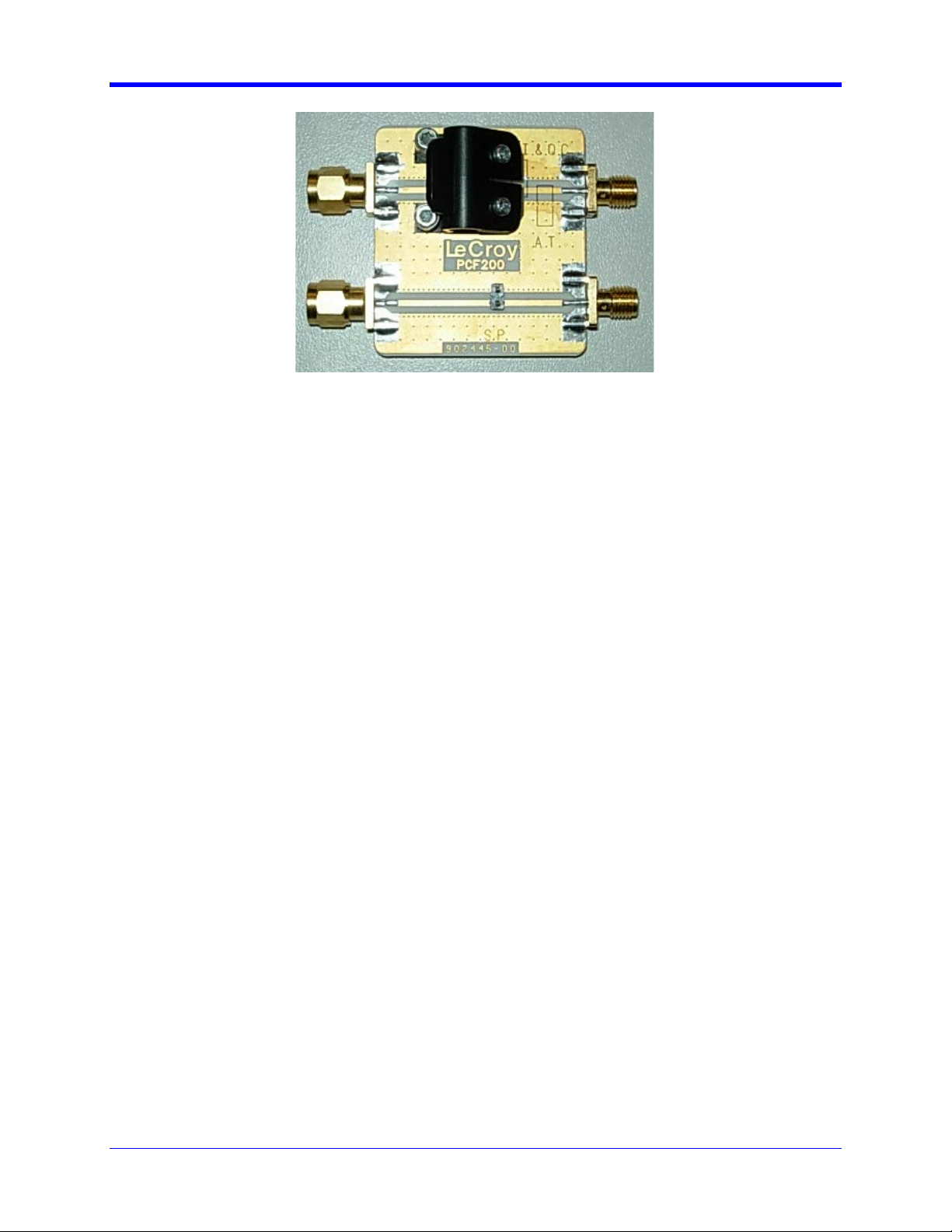
PCF200 Fix tu re Overview
Major components of the PCF200 fixture are shown in the following figure:
• SMA male connector Fast Edge input.
• SMA female connector output to AUX IN for 50-ohm termination.
• Clip for connection of Solder-In probes.
• 2-pins header for connection of Square-Pin probes.
8 917717 Rev C
Page 9
QPHY-DDR3 Software Option
Figure 1. PCF200 Deskew Fixture
A SMA male to BNC male 50-ohm cable is required to perform the calibration.
System assembly is accomplished in the following steps:
1. Connect the BNC end of the 50 ohm cable to the oscilloscope AUX IN input.
2. Connect the SMA end of the 50 ohm cable to the SMA female connector on the PCF200 fixture.
On oscilloscope models with a dedicated Fast Edge SMA output,
3a. Connect the PCF200 SMA male connector to the oscilloscope Fast Edge SMA output.
Skip to the next section.
On oscilloscope models without a dedicated Fast Edge SMA output,
3b. Using an BNC to female SMA adapter, connect the PCF200 SMA male connect to the
oscilloscope AUX OUT output.
4. Under Utilities → Utilities Setup, select Fast Edge from within the Aux Output tab.
Probe Connection to PCF200
The PCF200 provides multiple probe connectors for various kinds of probes. There are 2 circuits
depending on the type of probes to calibrate:
• The upper circuit is for Solder-In (SI) and Quick-Connect (QC) probes. This circuit can also be
used for AT probes using the designated area to apply the probe tips.
• The lower circuit is for Square-Pin (SP) probes.
Probes are connected electrically in a single-ended arrangement: the positive (+) side of the probe must
be connected to the signal trace, while the negative (-) side is connected to the ground plane. The
positive polarity marking is located on the tip end of the probe in white as a plus sign.
917717 Rev C 9
Page 10
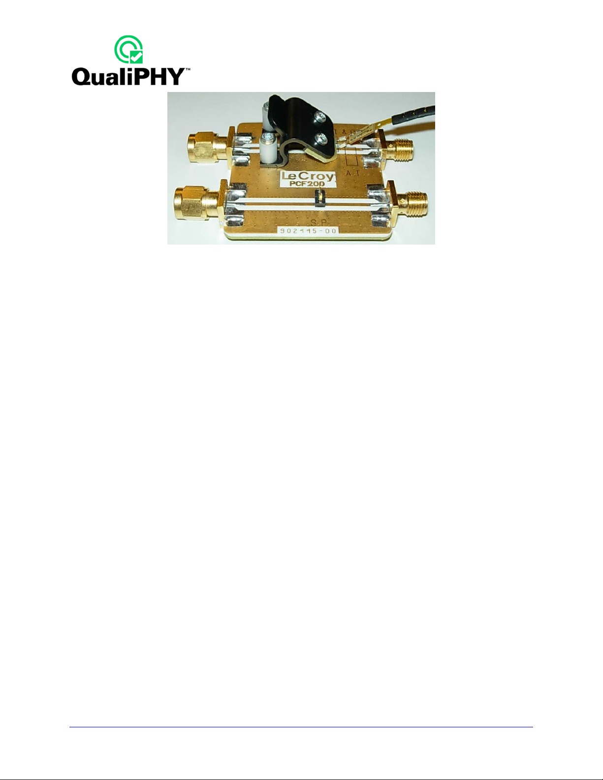
Figure 2. Differential probe properly connected to the fixture (Solder-In configuration)
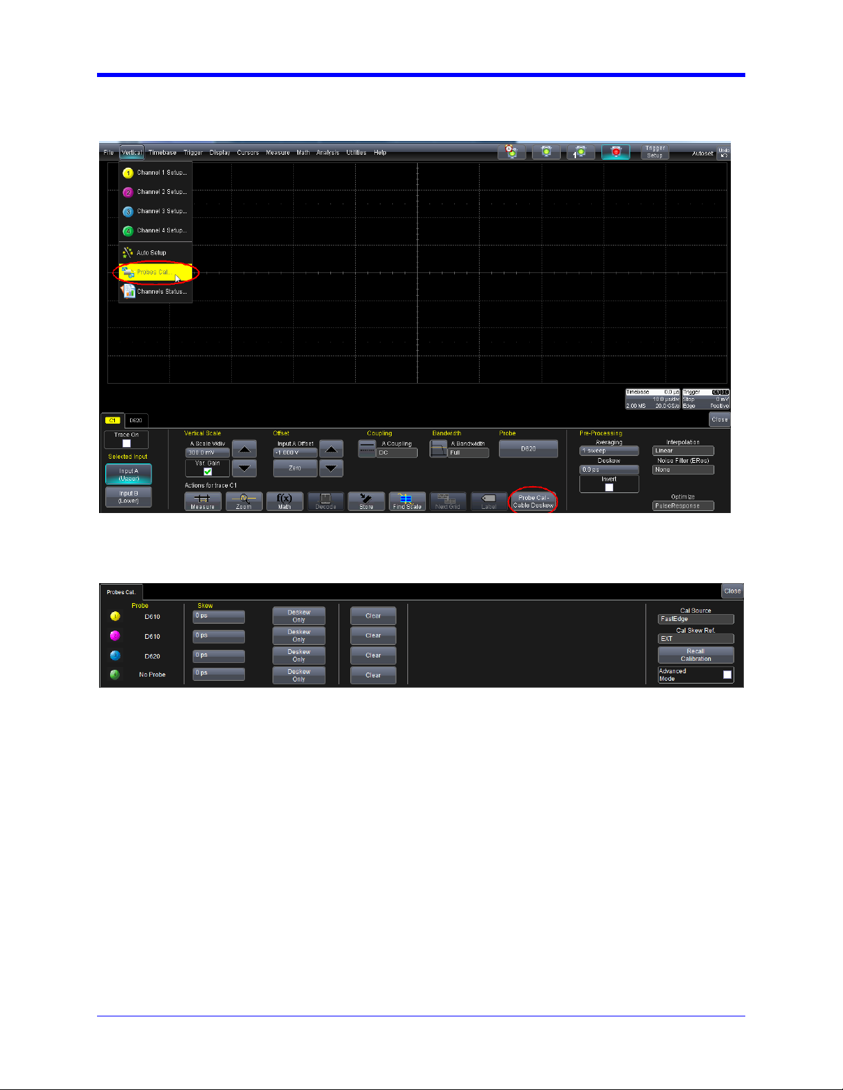
Probe Calibration Menu
10 917717 Rev C
Page 11
QPHY-DDR3 Software Option
The probe calibration menu can be accessed from the Vertical drop-down menu or from the channel
dialog:
Figure 3. A ccessing the probe calibration menu
Figure 4. Basic Probes Calibration menu
The information in the probe calibration menu is organized such that each row represents the information
for a given channel, and each column represents the calibration information or control for that channel.
Probe Calibration P ro c e dure
Depending on the compliance test that is to be performed, probes must connect with certain channels.
This is especially important when probes of different models are used simultaneously. The connection
setup for a particular test can be found in the pop-up dialog box after pressing the start button in Qualiphy.
Should probes be calibrated on the wrong channel, this procedure must be rerun.
Complete the following to properly deskew each probe.
1. Connect probes to their respective channel.
2. Select FastEdge for Cal Source.
3. Select EXT for for Cal Skew Ref.
The following is to be performed separately with each probe.
917717 Rev C 11
Page 12

1. Connect the probe to the PCF200 Fixture.
2. Press the Deskew Only button in the appropriate row representing the channel to be deskewed.
Now you are ready to probe the circuit and perform your measurements. If power is interrupted during
your measurements, reboot the oscilloscope and manually recall your settings.
12 917717 Rev C
Page 13

QPHY-DDR3 Software Option
BASIC FUNCTIONALITY
The functionality is extracted from JEDEC Standard No. JESD79-3D, section 3.
The DDR3 SDRAM is a high-speed dynamic random-access memory internally configured as an eight-
bank DRAM. The DDR3 SDRAM uses an 8n prefetch architecture to achieve high-speed operation. The
8n prefetch architecture is combined with an interface designed to transfer two data words per clock cycle
at the I/O pins. A single read or write operation for the DDR3 SDRAM consists of a single 8n-bit wide, four
clock data transfer at the internal DRAM core and two corresponding n-bit wide, one-half clock cycle data
transfers at the I/O pins.
Read and write operation to the DDR3 SDRAM are burst oriented, start at a selected location, and
continue for a burst length of eight or a “chopped” burst of four in a programmed sequence. Operation
begins with the registration of an Active command, which is then followed by a Read or Write command.
The address bits registered coincident with the Active command are used to select the bank and row to
be activated
(BA0-BA2 select the bank; A0-A15 select the row; refer to “DDR3 SDRAM Addressing” on page 15 for
specific requirements). The address bits registered coincident with the Read or Write command are used
to select the starting column location for the burst operation, determine if the auto precharge command is
to be issued (via A10), and select BC4 or BL8 mode on the fly (via A12) if enabled in the mode register.
Prior to normal operation, the DDR3 SDRAM must be powered up and initialized in a predefined manner.
917717 Rev C 13
Page 14
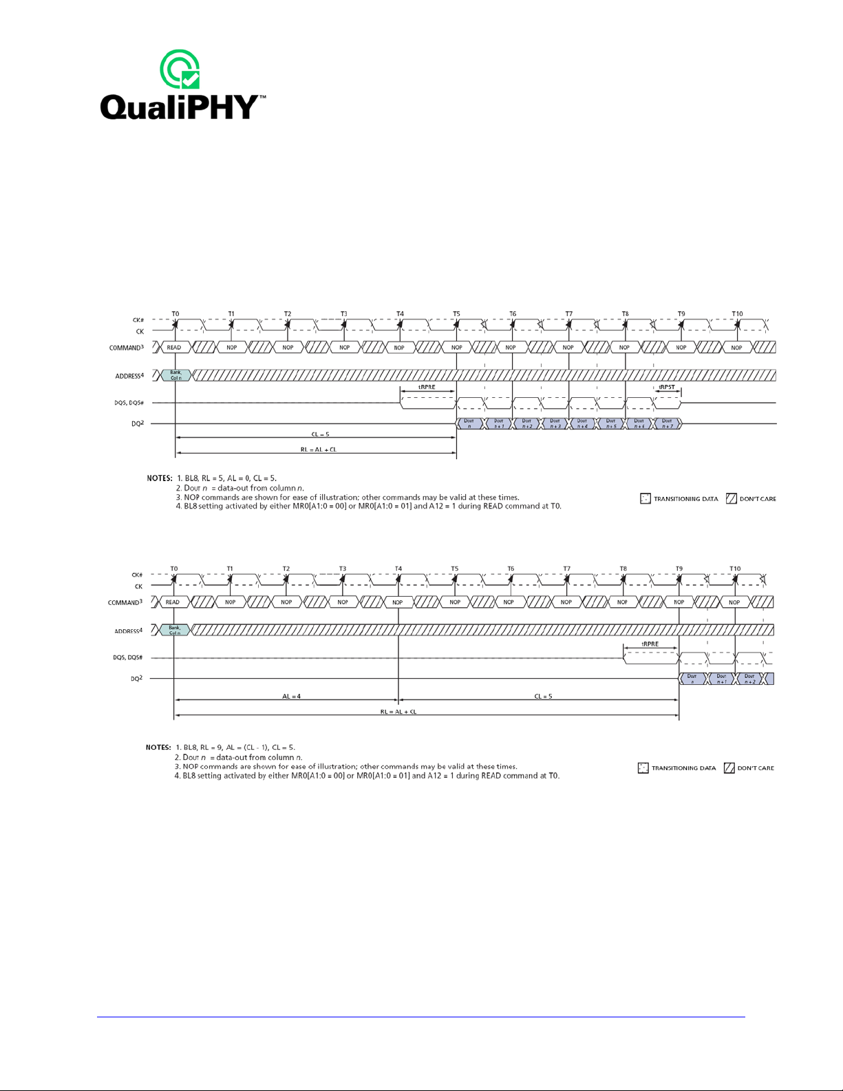
READ Burst Operation
During a READ or WRITE command, DDR3 supports BC4 and BL8 on the fly using address A12 during
the READ or WRITE (AUTO PRECHARGE can be enabled or disabled).
• A12 = 0, BC4 (BC4 = burst chop, tCCD = 4).
• A12 = 1, BL8.
• A12 is used only for burst length control, not as a column address.
Figure 5. READ Burst Operation RL = 5 (AL = 0, CL = 5, BL8) [JESD79-3D Figure 25]
Figure 6. READ Burst Operation RL = 9 (AL = 4, CL = 5, BL8) [JESD79-3D Figure 26]
14 917717 Rev C
Page 15

QPHY-DDR3 Software Option
WRITE Burst Operation
During a READ or WRITE command, DDR3 supports BC4 and BL8 on the fly using address A12 during
the READ or WRITE (AUTO PRECHARGE can be enabled or disabled).
• A12 = 0, BC4 (BC4 = burst chop, tCCD = 4).
• A12 = 1, BL8.
• A12 is used only for burst length control, not as a column address.
Figure 7. Write Timing Definition and Parameters [JESD79-3D Figure 43]
917717 Rev C 15
Page 16

USING QUALIPHY DDR3
QualiPHY DDR3 guides the user, step-by-step, through each of the source tests described in JEDEC
Standard No. 79-3D. To do this, the user must setup a test session.
Users choose test configurations to run. There are several pre-loaded test configurations including:
1) Clock tests DDR3-1333 (1 Probe)
2) CKdiff-DQse-DQSdiff 1333 Write Burst (3 probes)
3) CKdiff-DQse-DQSdiff 1333 Read Burst (3 probes)
4) Eye Diagram (3 Probes Debug)
5) Eye Diagram with CS enabled (4 Probe, fixG)
6) Add/Ctrl tests DDR3-1333 (4 probes, fixG)
7) PrePostamble tests (3 Probes, fixG)
D1) Demo of All tests
The pre-loaded configurations provide quick and easy ways to begin compliance testing. You can create
your own custom configurations (see the Customizing QualiPHY topic for details).
The variables are pre-loaded with the standard settings for compliance testing; however, the user may
choose to create their own configuration with the variables set as desired.
QUALIPHY COMPLIANCE TEST PLATFORM
QualiPHY is LeCroy’s compliance test framework which leads the user through the compliance tests.
QualiPHY displays connection diagrams to ensure tests run properly, automates the oscilloscope setup,
and generates complete, detailed reports.
The QualiPHY software application automates the test and report generation.
16 917717 Rev C
Page 17

QPHY-DDR3 Software Option
Figure 8. Report menu in QualiPHY General Setup
917717 Rev C 17
Page 18

See the QualiPHY Operator’s Manual for more information on how to use the QualiPHY framework.
Figure 9. The Test Report includes a summary table with links to the detailed test results
18 917717 Rev C
Page 19

QPHY-DDR3 Software Option
Oscilloscope Option Key Installation
An option key must be purc hased to enable the QPHY-DDR 3 option. Call LeCroy Customer Support to
place an order and receive the code.
Enter the key and enable the purchased option as follows:
1. From the oscilloscope menu select Utilities Utilities Setup.
2. Select the Options tab and click the Add Key button.
3. Enter the Key Code using the on-screen keyboard.
4. Restart the oscilloscope to activate the option after installation.
Typical (Recommended) Configuration
QualiPHY software can be executed from the oscilloscope or a host computer. The first step is to install
QualiPHY. Please refer to the QualiPHY Operator’s Manual for installation instructions.
LeCroy recomm ends running Quali PHY on an oscillos cope equipped with Dua l Monitor Dis play capabilit y
(Option DMD-1 for oscilloscopes where this is not standard). This allows the waveform and
measurements to be shown on the oscilloscope LCD display while the QualiPHY application and test
results are displayed on a second monitor.
By default, the oscilloscope appears as a local host when QualiPHY is executed in the oscilloscope.
Follow the steps under Oscilloscope Selection (as follows) and check that the IP address is 127.0.0.1.
Remote (Network) Configuration
It is also possible to install and run QualiPHY on a host computer, controlling the oscilloscope with a
Network/LAN Connection.
The oscilloscope must already be configured, and an IP address (fixed or network-assigned) must already
be established.
Oscilloscope Selection
Set up the oscilloscope using QualiPHY over a LAN (Local Area Network) by doing the following:
1. Mak e sure the host computer is connect ed to the same LAN as the oscilloscop e. If unsure, contact
your system administrator.
2. From the oscilloscope menu, select Utilities Utilities Setup.
3. Select the Remote tab.
4. Verify the oscilloscope has an IP address and the control is set to TCP/IP.
5. Run QualiPHY in the host computer and click the General Setup button.
6. Select the Connection tab.
7. Enter the IP address from step 4 (previous).
8. Click the Close button.
QualiPHY is now ready to control the oscilloscope.
917717 Rev C 19
Page 20

QualiPHY tests the oscilloscope connection after clicking the Start button. The system prompts you if
there is a connection problem. QualiPHY’s Scope Selector function can also be used to verify the
connection. Please refer to the QualiPHY Operator’s Manual for explanations on how to use Scope
Selector and other QualiPHY functions.
Accessing the QPHY-DDR3 Software using QualiPHY
This topic provides a basic overview of QualiPHY’s capabilities. Please refer to the QualiPHY Operator’s
Manual for detailed information.
Access the QPHY-DDR3 software using the follo wing s teps:
1. Wait for the oscilloscope to start and have its main application running.
2. Launch Qu aliPHY from the Analysis menu if installed on the oscilloscope or fr om the desktop ic on if
installed on a host computer.
3. From the Q ualiPH Y main window (as f ollows), select Standard, then DDR3 from the pop-up m enu (if
not already selected) . If yo u check the Pause on Fa ilure b ox (circ led) QualiPH Y prompts to retr y the
test in the case of a failure.
20 917717 Rev C
Page 21

QPHY-DDR3 Software Option
Figure 10. QualiPHY main menu and compliance test Standard selection menu
917717 Rev C 21
Page 22

4. Click the Configuration button in the QualiPHY main menu:
5. Select a configuration from the pop-up menu:
Figure 11. QualiPHY configuration selection menu
6. Click Start.
7. Follow the pop-up window prompts.
22 917717 Rev C
Page 23

QPHY-DDR3 Software Option
Customizing QualiPHY
The predefined configur ations in t he Configuration sc reen can not be m odified. Ho wever, you can create
your own test confi gurat ion s b y copying one of the standard test conf ig urat ions a nd making modifications.
A description of the test is also shown in the description field when selected.
Figure 12. QualiPHY test item selection menu
917717 Rev C 23
Page 24

Once a custom conf iguration is defined, scr ipt variables and the test limits can be changed by us ing the
Variable Setup and Limits Manager from the Edit/View Configuration window.
Figure 13. Variable Setup and Limits Manager windows
24 917717 Rev C
Page 25

QPHY-DDR3 Software Option
QPHY-DDR3 Operation
After pressing Start in the QualiPHY menu, the softwar e instructs how to set up the test using pop-up
connection diagrams and dialog boxes.
Figure 14. Start button
Figure 15. Example of pop-up connec tion diagram and dialog box
917717 Rev C 25
Page 26

QPHY-DDR3 TEST CONFIGURATIONS
Configurations include variable settings and limit sets as well, not just test selections. See the section for
a description of each variable value and its default value. See the QPHY-DDR3 Limit Sets section for
more information about the limit sets.
1) Clock tests DDR3-1333 (1 Probe)
This configuration runs all of the clock tests. All of the variables are set to their defaults. The limit set in
use is DDR3-1333. The tests run are:
• tCK(avg)
• tCK(abs)
• tCH(avg)
• tCL(avg)
• tCH(abs)
• tCL(abs)
• tJIT(duty)
• tJIT(per)
• tJIT(CC)
• tERR(n per)
2) CKdiff-DQse-DQSdiff 1333 Write Burst (3 Probes)
This configuration runs all of the tests that are run on write bursts of the DDR3 signals in which 3 probes
are required. All of the variables are set to their defaults. The limit set in use is DDR3-1333. The tests run
are:
• Eye Diagram – Write Bursts (Inputs)
• SlewR
• SlewF
• VIH(ac)
• VIH(dc)
• VIL(ac)
• VIL(dc)
• tDVAC
• tVAC
• AC Overshoot peak amplitude
• AC Overshoot area above VDDQ
• AC Undershoot Peak Amplitude
• AC Undershoot Area below VSSQ
• VOH(ac/dc)
26 917717 Rev C
Page 27

• VOL(ac/dc)
• VSWING
• tQSH
• tQSL
• tHP, tQHS
• tLZ(DQ)
• tLZ(DQS)
• tRPRE
• tDQSS
• tDQSH
• tDQSL
• tDIPW
• tDSS
• tDSH
• tDS(base + derated)
QPHY-DDR3 Software Option
• tDH(base + derated)
917717 Rev C 27
Page 28

3) CKdiff-DQse-DQSdiff 1333 Read Burst (3 Probes)
This configuration runs all of the tests that are run on read bursts of the DDR3 signals in which 3 probes
are required. All of the variables are set to their defaults. The limit set in use is DDR3-1333. The tests run
are:
• Eye Diagram – Read Bursts (Outputs)
• SRQr
• SRQf
• tDQSQ
• tQH
• tDQSCK
4) Eye Diagram (3 Probes Debug)
This configuration runs the Eye Diagram tests on both the read bursts and the write bursts. All of the
variables are set to their defaults. The limit set in use is DDR3-1333. The tests run are:
• Eye Diagram – Write Bursts (Inputs)
• Eye Diagram – Read Bursts (Outputs)
5) Eye Diagram with CS Enabled (4 Probes Debug)
This configuration runs the Eye Diagram tests on both the read bursts and the write bursts. All of the
variables are set to their defaults except the Use Chip Select is set to Yes. The limit set in use is DDR3-
1333. The tests run are:
• Eye Diagram – Write Bursts (Inputs)
• Eye Diagram – Read Bursts (Outputs)
6) CKDiff-DQse-DQS-ADD/CTRLse (4 Probes Debug)
• SlewR
• SlewF
• VIH(ac/dc)
• VIL(ac/dc)
• VSWING
• AC Overshoot Peak Amplitude
• AC Overshoot Area above VDDQ
• AC Undershoot Peak Amplitude
• AC Undershoot Area below VSSQ
• tIS (base + derated)
28 917717 Rev C
Page 29

QPHY-DDR3 Software Option
• tIH (base + derated)
• tIPW
7) CKdiff-DQse-DQSp-DQsn (4 probes test, each DQS signal probed single ended)
• VSEH(ac)
• VSEL(ac)
• VIX(ac)
• AC Overshoot Peak Amplitude
• AC Overshoot Area above VDDQ
• AC Undershoot Peak Amplitude
• AC Undershoot Area below VSSQ
• SlewR
• SlewF
8) CKp-CKn-DQse-DQSdiff (4 probe test, each CK signal is probed single ended)
• VSEH(ac)
• VSEL(ac)
• AC Overshoot Peak Amplitude
• AC Overshoot Area above VDDQ
• AC Undershoot Peak Amplitude
• AC Undershoot Area below VSSQ
• SlewR
• SlewF
9) Vref tests
• Vref(dc)
D1) Demo of All Tests
This configuration uses the saved waveforms found in the D:\Waveforms\DDR3 folder and run all of the
tests. All of the variables are set to their defaults except Use Stored Waveforms is set to Yes and Use
Stored Trace for Speed Grade is set to Yes. The limit set in use is DDR3-1333. All supported tests are
run.
QPHY-DDR3 VARIABLES
General Variables
The following variables are used by all configurations. They can be used in conjunction with the test
selection and limit set selection to create custom configurations.
DUT Spe ed Gr a de in MT/s
Transfer speed of the DUT. Used to set the oscilloscope timebase and sampling rate, see Clock Period
Per Screen Division variable for more explanation. Choose between: 800, 1066, 1333, 1600 MT/s or
custom. Default is 1333MT/s.
917717 Rev C 29
Page 30

DQ Signal Name
Select name of data (DQ) SUT. Choose between available DDR signal names. Default is DQ0.
DQS Signal Name
Select name of strobe (DQS) SUT. Choose between available DDR signal names. Default is DQS0.
Clock Signal Name
Select name of clock (CK) SUT. Choose between available DDR signal names. Default is CK.
DUT Power Supply VDDQ
Value of VDDQ used to compute test limits as specified by Jedec standard. Default is 1.5 V.
4th Probe Names
Chip Select Signal Name
Select the name of the Chip Select SUT. Choose between available DDR signal names. Default is CS0.
Script Settings
Save Acquired Waveforms
Saved waveforms can be used later in demonstration or optimized version of script. Choose between Yes
or No. The default is No. This setting is ignored (no save) if using stored waveforms is enabled and in
Demo mode.
Silent mode control
No more interaction with the user when silent mode is on. Choose between Yes or No. Default is No. This
is useful to let the test run without interruption in the background.
Stop On Test to review results
When set to Yes, the script stops after each test allowing you to view the results. The setup is saved so
the oscilloscope settings can be modified by the user. On resume, the setup is recalled. Any new
acquisition done may cause the script to produce unexpected results.
Use Chip Sel ect (re q uir e one mor e pr ob e)
When set to Yes, the script will use the chip select signal to correctly identify read and write bursts in
multi-ranked systems. The chip select line is used in conjunction with the Overall Read Latency and
Overall Write Latency variables to correctly identify the proper read and write bursts.
Waveform Path
Specify the path on the oscilloscope to save/recall waveforms. When not in Demo Mode and when Save
acquired waveforms is enabled, the waveforms are saved in this folder. When set to Demo Mode or
when Use stored trace for pixel clock measure, wavef orm s are also available from this folder. The
default location is D:\Waveforms\DDR3.
Latency Setting
Overall Read Latency
This is used to specify the Delay between DDR command (Read) to first data bit of related read burst.
This is needed when using the Chip Select line to correctly identify read and write bursts in multi-ranked
systems. This latency is measured in clock periods.
30 917717 Rev C
Page 31

QPHY-DDR3 Software Option
Overall Write Latency
This is used to specify the Delay between DDR command (Write) to first data bit of related read burst.
This is needed when using the Chip Select line to correctly identify read and write bursts in multi-ranked
systems. This latency is measured in clock periods.
Demo Settings
Use Stored Waveforms
When enabled, previously stored DDR3 waveforms is used. The default is No.
Recalled Waveform File Index (5 digits)
Enter the 5 digits number corresponding to the index of the file you want to recall. The default is 00000.
Define format used to set trace names
This setting stores a saved waveform naming format or convention. The choices are LeCroy or Dialog.
The LeCroy choice produces waveform names automatically by the software. Dialog prompts the user
for custom waveform names. The default setting is LeCroy.
Use Stored Trace for Spe ed Grade
This is an optimization used specifically to measure the clock frequency only once. Choose from Yes or
No values and the default selection is No.
917717 Rev C 31
Page 32

Advanced Settings
Clock Period per Screen Division
Oscilloscope timebase and sampling rate is set to acquire the given number of clock cycle per display
horizontal division at a given DUT Speed Grad in MT/s and for a Max. Number of Samples Per Clock
Period. The default is 3341 clock periods (this gives a 10us/div timebase at 667 MT/s and 3.3MS max for
100 samples per period).
Timebase = [Clock Period Per Screen Division] / ([DUT Speed Grade in MT/s] / 2 * 1e6)
Maximum Samples = [Max. Number Of Samples Per Clock Period] * [Cl o c k Pe rio d Per Scr een
Division] * 10
Number of cycl es for Cl ock test
Jedec standard requires 200 cycles for the Clock compliance test.
This is the default value of this variable. Any positive number can be entered.
Max. Number Of Samples Per Clock Period
The oscilloscope timebase and sampling rate is set to acquire the given number of points per clock
period. The oscilloscope is always set to at least acquire at 20GS/s. Also, if an oscilloscope with greater
than 6GHz bandwidth is used, the bandwidth is limited to 6GHz. See the Clock Period Per Screen
Division topic for more details. Choose between 10;20;50;100;200;500 or 1000. The default value is 100.
Configuration Specific Variables
The following variables are specific to the configuration in which they appear under. Some of these
variables appear under multiple configurations.
XX Channel Gain
Allows the user to manually specify the vertical scale in V/div for XX SUT. XX can be Clock, DQ, DQS,
DQSn, ADD/CTRL, or DM. The default is 0 for auto-scale.
XX Channel Index
Allows the user to manually specify the channel XX SUT. XX can be Clock, DQ, DQS, DQSn, ADD/CTRL,
or DM. Default is 1 for CK, 2 for DQS, 3 for DQ and 4 for others
XX Channel Invert
Allows the user to invert XX SUT. XX can be Clock, DQ, DQS, DQSn, ADD/CTRL, or DM. The default is
False.
XX Channel Offset
Allows the user to manually specify the offset in Volts for XX SUT. XX can be Clock, DQ, DQS, DQSn,
ADD/CTRL, or DM. The default is 0 for auto-scale.
Speed Bin Paramters
CAS Latency
Allows the user to specify the CAS Latency (CL) used to define tCK(avg) limits (see tables 61 to 64 in
JEDEC Standard).
32 917717 Rev C
Page 33

QPHY-DDR3 Software Option
CAS Write Latency
Allows the user to specify the CAS Write Latency (CWL) used to define tCK(avg) limits (see tables 61 to
64 in JEDEC Standard).
Speed Bin
Allows the user to specify the Speed Bin used to define tCK(avg) limits (see tables 61 to 64 in JEDEC
Standard).
917717 Rev C 33
Page 34

QPHY-DDR3 LIMIT SETS
DDR3-800
This corresponds to the JEDEC JESD79-3D DDR3 standard specification limits for 800 MT/s.
DDR3-1066
This corresponds to the JEDEC JESD79-3D DDR3 standard specification limits for 1066 MT/s.
DDR3-1333
This corresponds to the JEDEC JESD79-3D DDR3 standard specification limits for 1333 MT/s..
DDR3-1600
This corresponds to the JEDEC JESD79-3D DDR3 standard specification limits for 1600 MT/s.
QPHY-DDR3 TESTS
Clock Tests
All time measure on clock CK are done at level VREF.
tCK(avg), Average Clock Period
tCK(avg) is calculated as the average clock period across any consecutive 200 cycle window, where each
clock period is calculated from rising edge to rising edge.
tCK(abs), Absolute Clock Period
tCK(abs) is defined as the absolute clock period, as measured from one rising edge to the next
consecutive
rising edge. tCK(abs) is not subject to production test.
tCH(avg), Average High Pulse Width
tCH(avg) is defined as the average high pulse width, as calculated across any consec uti ve 200 hi gh
pulses.
34 917717 Rev C
Page 35

QPHY-DDR3 Software Option
tCL(avg), Average Low Pulse Width
tCL(avg) is defined as the average low pulse width, as calculated across any consecutive 200 low pulses.
tCH(abs), Absolute High Pulse Width
tCH(abs) is the absolute instantaneous clock high pulse width, as measured from one rising edge to the
following falling edge.
tCL(abs), Absolute Low Pulse Width
tCL(abs) is the absolute instantaneous clock low pulse width, as measured from one falling edge to the
following rising edge.
tJIT(duty), Half Period Jitter
tJIT(duty) is defined as the cumulative set of tCH jitter and tCL jitter over 200 consecutive cycles.
tCH jitter is the largest deviation of any single tCH from tCH(avg).
tCL jitter is the largest deviation of any single tCL from tCL(avg).
tJIT(duty) = Min/max of {tJIT(CH), tJIT(CL)}
where,
tJIT(CH) = {tCHi - tCH(avg) where i=1 to 200}
tJIT(CL) = {tCLi - tCL(avg) wher e i=1 to 200}
tJIT(per), Clock Period Jitter
tJIT(per) is defined as the largest deviation of any signal tCK from tCK(avg).
tJIT(per) = Min/max of {tCKi - tCK(avg) where i = 1 to 200}.
tJIT(per) defines the single period jitter when the DLL is already locked.
tJIT(per,lck) uses the same definition for single period jitter, during the DLL locking period only.
tJIT(per) and tJIT(per,lck) are not subject to production test.
tJIT(cc), Cycle to Cycle Period Jitter
tJIT(cc) is defined as the absolute difference in clock period between two consecutive clock cycles.
tJIT(cc) = Max of |{tCKi +1 - tCKi}|.
tJIT(cc) defines the cycle to cycle jitter when the DLL is already locked.
tJIT(cc,lck) uses the same definition for cycle to cycle jitter, during the DLL locking period only.
tJIT(cc) and tJIT(cc,lck) are not subject to production test.
917717 Rev C 35
Page 36

tERR(n per), Cumulative Error
tERR is defined as the cumulative error across n multiple consecutive cycles from tCK(avg). tERR is not
subject to production test.
There are 12 different tests:
tERR(2per), tERR (3per), tERR (4per), tERR (5per), tERR(6per), tERR (7per), tERR (8per), tERR (9per),
tERR (10per), tERR (11per), tERR (12per), tERR (13-50per),
Eye Diagram
Write Burst (Inputs)
This is an informational only test that creates the eye diagram of all of the write bursts found in the
acquisition. The Eyes are created for both the Data signal and the Strobe signal and shown on the
screen at the same time to allow for debugging of strobe timing.
Read Burst (Outputs)
This is an informational only test that creates the eye diagram of all read bursts found in the acquisition.
The Eyes are created for both the Data signal and the Strobe signal and shown on the screen at the same
time to allowing for strobe timing debugging.
Electrical Tests
Write Bursts (Inputs)
Slew (Input Slewrate)
This test applies to all input signals.
SlewR and SlewF
Apply to all input signals.
The input signal minimum slew rate is to be maintained over the range from VREF to VIH(ac) min for
rising edges (SlewR) and the range from VREF to VIL(ac) max for falling edges (SlewF) of single-ended
signal. This test is informational only.
36 917717 Rev C
Page 37

QPHY-DDR3 Software Option
For differential signals (e.g. CK - CK#) slew rate for rising edges is measured from Vihdiffmin to
Vihdiffmax. This test is informational only .
Figure 16. AC input test signal waveform [JESD79-3D figure 94]
Logic Levels
VIH(ac), maximum AC input logic high
Measure the local maximum value from VREF to VREF of the high pulse histogram. If multiple pulses are
measured, take the lowest number and the highest number as the worst cases.
The lowest number must be greater than or equal to the minimum limit and the highest number must be
less than or equal to the maximum limit.
VIH(dc), minimum DC input logic high
Measure the local minimum and maximum values from the first VIH(ac)min crossing point to the time
corresponding to VIH(dc)min crossing a 1V/ns slewrate slope to VREF. If multiple pulses are measured,
take the lowest, respectively the highest, number as the worst case.
917717 Rev C 37
Page 38

The local minimum must be greater than or equal to the minimum limit. The local maximum must be less
than or equal to the maximum limit.
VIL(ac), maximum AC input logic low
Measure the local minimum value from VREF to VREF of the low pulse histogram. If multiple pulses are
measured, take the lowest number and the highest number as the worst cases.
The lowest number must be greater than or equal to the minimum limit and the highest number must be
less than or equal to the maximum limit.
VIL(dc), minimum DC input logic low
Measure the local minimum and maximum values from the first VIL(ac)max crossing point to the time
corresponding to VIL(dc)max crossing a 1V/ns slewrate slope to VREF. If multiple pulses are measured,
take the lowest, respectively the highest, number as the worst case.
The local minimum must be greater than or equal to the minimum limit. The local maximum must be less
than or equal to the maximum limit.
Read Bursts (Outputs)
SRQ (Output Slew Rate)
SRQr and SRQf
Apply to all output signals.
The output slew rate is measured from VOL(ac) to VOH(ac) for the rising edge and from VOH(ac) to
VOL(ac) for the falling edge
Timing Tests
Read Burs ts
tDQSQ, DQS-DQ Skew for DQS and Associated DQ Signals
Maximum skew between the DQS line and the associated DQ line within a read burst
38 917717 Rev C
Page 39

QPHY-DDR3 Software Option
Measure timing from DQS at VREF to DQ rising at VIH(ac)min and falling at VIL(ac)max.
Figure 17 - Data output (read) timing [JESD79-3D figure 27]
tQH, DQ/DQS Output Hold Time From DQS
This measures the timing from DQS at VREF to DQ at VIH(dc) (rising edge) or VIL(dc) (falling edge). See
figure 22.
tDQSCK, DQS Output Access Time from CK/CK #
Time from CK rising at VREF level to DQS rising at VREF level.
917717 Rev C 39
Page 40

Figure 18. Burst read operatio n [JESD79-3D figure 28]
This is a measure similar to tDQSS but on the Read frame (the result can be negative).
40 917717 Rev C
Page 41

QPHY-DDR3 Software Option
Write Bursts
tDQSS, DQS latching rising transitions to associated CK edge
CK rising edge at VREF level to DQS rising edge at VREF level, see Figure 21.
Figure 19. Burst write operation [JESD79-3D figure 43]
tDQSH, DQS Input High Pulse Width
DQS High pulse width at VREF level, see Figure 22.
Figure 20. Data input (write) timing [JESD79-3D figure 43]
tDQSL, DQS Input Low Pulse Width
DQS Low pulse width at VREF level, see Figure 22.
917717 Rev C 41
Page 42

tDSS, DQS Falling Edge to CK Setup Time
Time from DQS falling edge at VREF level to CK rising edge at VREF level, see Figure 22.
tDSH, DQS Falling Edge Hold Time from CK
Time from CK rising edge at VREF level to DQS falling edge at VREF level, see Figure 22.
tDS(base), DQ and DM Input Setup Time
Input waveform timing tDS with differential data strobe enabled, is referenced from the input signal
crossing at the VIH(ac)min level to the differential data strobe crosspoint at VREF for a rising signal, and
from the input signal crossing at the VIL(ac)max level to the differential data strobe crosspoint at VREF for
a falling signal applied to the device under test
DQS and DQS# signals must be monotonic between VIL(dc)max and VIH(dc)min.
Setup (tDS) nominal slew rate for a rising signal is defined as the slew rate between the last crossing of
VREF(dc) and the first crossing of VIH(ac)min. Setup (tDS) nominal slew rate for a falling signal is defined
as the slew rate between the last crossing of VREF(dc) and the first crossing of VIL(ac)max.
JESD79-3D Tables 73 and 74 explain the limit compensation versus the slewrate of the measured
signals. Timing limits are initially specified for input slewrate of 1V/ns for single-ended signals and 2V/ns
for differential signal (for DQS and CK).
tDH(base), DQ and DM Input Hold Time
Input waveform timing tDH with differential data strobe enabled, is referenced from the differential data
strobe crosspoint at VREF to the input signal crossing at the VIH(dc)min level for a falling signal and from
the differential data strobe crosspoint at VREF to the input signal crossing at the VIL(dc)max level for a
rising signal applied to the device under test
DQS and DQS# signals must be monotonic between VIL(dc)max and VIH(dc)min.
Hold (tDH) nominal slew rate for a rising signal is defined as the slew rate between the last crossing of
VIL(dc)max and the first crossing of VREF(dc). Hold (tDH) nominal slew rate for a falling signal is defined
as the slew rate between the last crossing of VIH(dc)min and the first crossing of VREF(dc).
JESD79-3D Tables 43 and 44 explain the limit compensation versus the slewrate of the measured
signals. Timing limits are initially specified for input slewrate of 1V/ns for single-ended signals and 2V/ns
for differential signal (for DQS and CK).
Four Probe tests measurements using ADDR/CTL
tIS /tIH (base) - Address and Control Input Setup Time (Hold Time)
Input waveform timing is referenced from the input signal crossing at the VIH(ac)min level to the
differential clock crosspoint at VREF for a rising signal, and from the input signal crossing at the
VIL(ac)max level to the differential clock crosspoint at VREF for a falling signal applied to the device
under test. See Figure 23 below.
42 917717 Rev C
Page 43

QPHY-DDR3 Software Option
Figure 21: tIS illustration (Figure 111 from JESD79-3E)
Setup (tIS) nominal slew rate for a rising signal is defined as the slew rate between the last crossing of
VREF(dc) and the first crossing of VIH(ac)min. Setup (tIS) nominal slew rate for a falling signal is defined
as the slew rate between the last crossing of VREF(dc) and the first crossing of VIL(ac)max.
Jedec JESD79-2E Specific Note 9 (page 95 to 100) with tables 46 and 47 explain the limit compensation
versus the slewrate of the measured signals. Timing limits are initially specified for input slewrate of 1V/ns
for single-ended signals and 2V/ns for differential signal (for DQS and CK).
tIPW, Control and Address Input pulse width for each input
Pulse width of a input signal is defined as the width between the first crossing of Vref(dc)
and the consecutive crossing of Vref(dc).
917717 Rev C 43
Page 44

VIX(ac), AC Differential Input Cross Point Voltage
The typical value of VIX(ac) is expected to be about 0.5 x VDDQ of the transmitting device and VIX(ac) is
expected to track variations in VDDQ. VIX(ac) indicates the voltage at which differential input signals must
cross.
Vref(DC)
It is the linear average of Vref (t) over a very long period of time (e.g., 1 sec). This average has to meet
the min/max requirements in Table below. Furthermore V(t) may temporarily deviate from Vref(DC) by no
more than +/- 1% VDD.
Figure 22: Vref table (Table 23 from JESD79-3E)
§ § §
44 917717 Rev C
 Loading...