

QPHY-BroadR-Reach
BroadR-Reach Serial Data
Operator’s Manual
Revision B – November, 201 3
Relating to the Following Release
Versions:
• Software Version Rev. 7.3
• BroadR-Reach Script Rev. 7.3
• Style Sheet Rev. 1.2.

700 Chestnut Ridge Road
Chestnut Ridge, NY, 10977-6499
Tel: (845) 425-2000, Fax: (845) 578 5985
teledynelecroy.com
© 2013 by Teledyne LeCroy . All rights reserved.
Teledyne LeCroy and other product or brand names are trademarks or requested trademarks of their
respective holders. Information in this publication supersedes all earlier versions. Specifications are
subject to change without notice.
922533 Rev B
November 2013

QPHY-BroadR-Reach Software Option
TABLE OF CONTENTS
INTRODUCTION TO QUALIPHY BROADR-REACH ..................................................... 5
Required Equipment ..................................................................................................................................... 5
USING QUALIPHY BROADR-REACH ........................................................................... 6
QUALIPHY COMPLIANCE TEST PLATFORM .............................................................. 7
Oscilloscope Option Key Installation ............................................................................................................. 9
Typical (Recommended) Configuration ......................................................................................................... 9
Remote (Network) Configuration .................................................................................................................. 9
Oscilloscope Selection .................................................................................................................................. 9
Accessing the QPHY-BroadR-Reach Software using QualiPHY ................................................................ 10
Customizing QualiPHY ................................................................................................................................ 12
Creating Custom Configurations ................................................................................................................. 13
QPHY-BroadR-Reach Operation ................................................................................................................ 15
BROADR-REACH MEASUREMENT PREPARATION ................................................. 16
Required T est Modes .................................................................................................................................. 16
Physical Setup ............................................................................................................................................ 16
QPHY-BROADR-REACH TEST CONFIGURATIONS .................................................. 17
QPHY-BROADR-REACH VARIABLES ........................................................................ 18
QPHY-BROADR-REACH LIMIT SETS ......................................................................... 19
QPHY-BROADR-REACH TEST DESCRIPTIONS ....................................................... 20
Test 1 - Transmitter Output Droop ....................................................................................................... 20
Test 2 - Transmitter Jitter (Master) and Transmit Clock Frequency .................................................... 22
Test 3- Transmitter Jitter (Slave) and Transmit Clock Frequency ....................................................... 24
Test 4 - Transmitter Distortion Test ..................................................................................................... 26
Test 5 - Transmitter Power Spectral Density (PSD) ............................................................................ 30
922533 Rev B 3

TABLE OF FIGURES
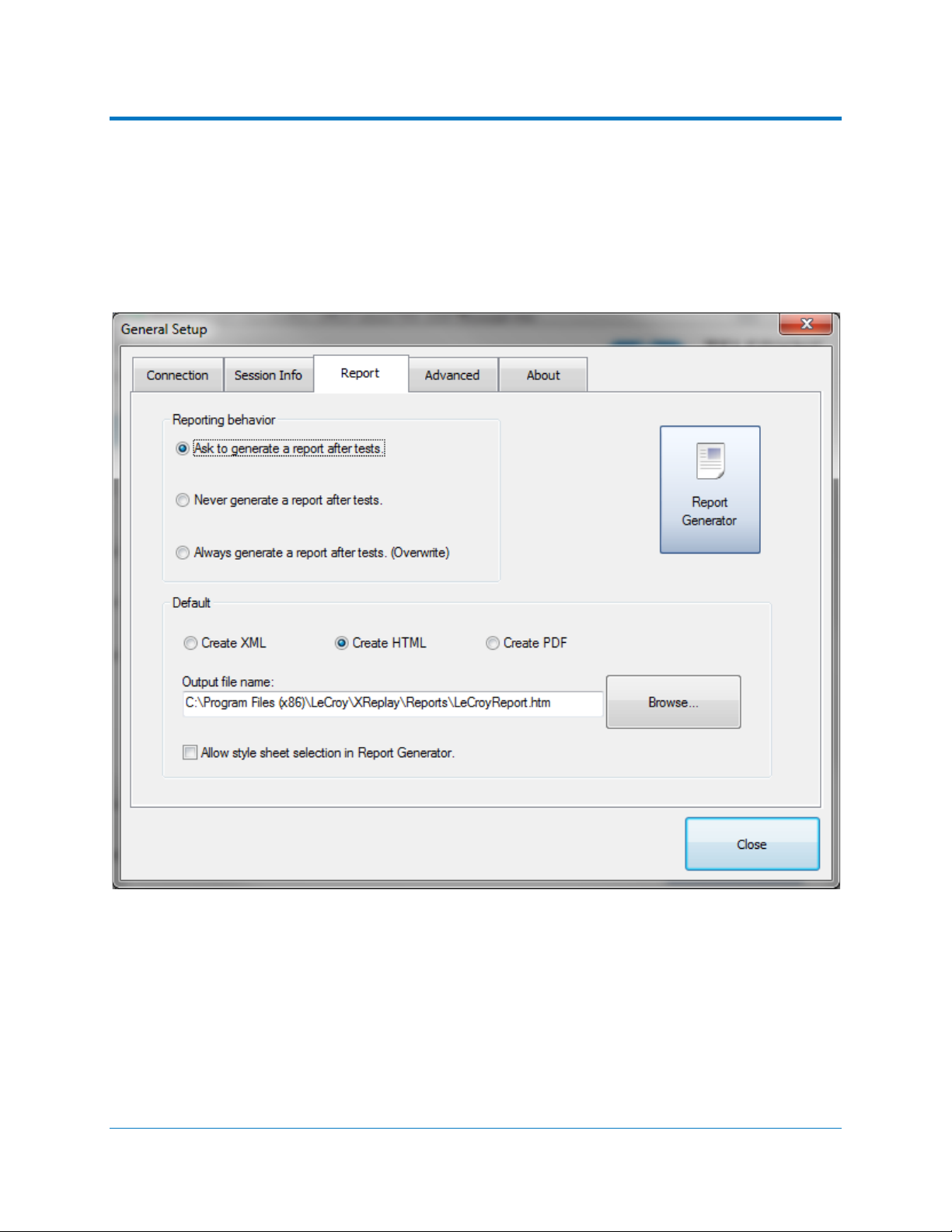
Figure 1 - Report menu in QualiPHY General Setup................................................................................ 7
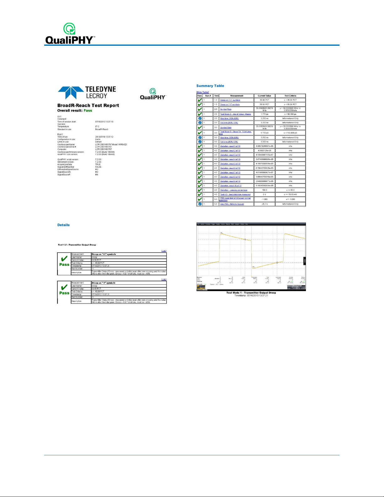
Figure 2 - The Test Report includes a summary table with links to the detailed test results ............. 8
Figure 3 - QualiPHY main menu and compliance test Standard selection menu ............................... 10
Figure 4 - QualiPHY configuration selection menu. .............................................................................. 11
Figure 5 - QualiPHY test item selection menu ....................................................................................... 12
Figure 6 - Variable Setup and Limits Manager windows ....................................................................... 14
Figure 7 - Star t bu tton ............................................................................................................................... 15
Figure 8 - Example of pop-up connection diagram and dial og b ox .................................................... 15
Figure 9 - Example of RJ45/UTP adapter ................................................................................................ 16
Figure 10 - Example of Custom SMA Breakout fixture .......................................................................... 17
Figure 11 – Definition of Droop Measurement ....................................................................................... 20
Figure 12 – Transmitter Output Droop .................................................................................................... 21
Figure 13 – Transmitter Output Droop Test Resul ts .............................................................................. 21
Figure 14 – Transmitter Jitter (Master) and Transmit Clock Frequency .............................................. 23
Figure 15 – Transmitter Jitter (Master) and Transmit Clock Frequency Test Results ........................ 23
Figure 16 – Transmitter Jitter (Slave) and Transmit Clock Frequency Setup ..................................... 24
Figure 17 – Transmitter Jitter (Slave) and Transmit Clock Frequency ................................................ 25
Figure 18 – Transmitter Jitter (Slave) and Transmit Clock Frequency Test Results .......................... 25
Figure 19 – Connection Diagram for Transmitter Distortion Test using TF-ENET-B ......................... 26
Figure 20 – Disturbing Sine Wave Characteristics ................................................................................ 27
Figure 21 – Transmitter Distortion Test Setup ....................................................................................... 27
Figure 20 – Transmitter Distortion .......................................................................................................... 28
Figure 19 – Transmitter Distortion Test Results .................................................................................... 29
Figure 20 – Transmitter Power Spectral Density (PSD) ........................................................................ 31
Figure 21 – Transmitter Power Spectral Density (PSD) Test Results .................................................. 31
4 922533 Rev B

QPHY-BroadR-Reach Software Option
INTRODUCTION TO QUALIPHY BROADR-REACH
QPHY-BroadR-Reach is an automated test package performing all of the normative real time
oscilloscope tests for sources in accordance with the BroadR-Reach Physical Layer Transceiver
Specification For Automotive Applications, v .2.0.
The software can be run on any Teledyne LeCroy Zi and Xi Series oscilloscope with at least 1 GHz
bandwidth and a sample rate of at least 10GS/s (WaveRunner series and up). The oscilloscope must
also be equipped with QPHY-BroadR-Reach and either the JTA2 (standard on all Zi series
oscilloscopes), SDAII, or SDAIII options.
Required Equipment
• Real time Teledyne LeCroy Oscilloscope meeting the above requirements (at least 1 GHz
bandwidth, and sample rate of at least 10GS/s)
o All LabMaster 9 Zi-A oscilloscopes
o All SDA/DDA/WaveMaster 8 Zi-A oscilloscopes
o SDA/DDA/WavePro 725Zi-A and higher bandwidth oscilloscopes
o WaveRunner 610 Zi and higher bandwidth oscilloscopes
o WaveRunner 104 MXi-A /Xi-A Series and higher bandwidth oscilloscopes
Note: If a WaveRunner Xi oscilloscope is being used, the XWEB option is additionally
required.
• QPHY-BroadR-Reach and either the JTA2, SDAII, or SDAIII options
Note: SDA software is included on all SDA and DDA oscilloscope models. JTA2 is
standard on all Zi series oscilloscopes.
• MATLAB Runtime Component 7.7 is required to run the MATLAB script for the distortion test
o Available for download from Teledyne LeCroy website
• A pair of SMA cables of equal length. Depending upon the oscilloscope model SMA/BNC
adapters may also be required.
Note: A Teledyne LeCroy ZD1000 Differential Probe or greater can alternatively be used
• AWG for Distortion Test - Teledyne LeCroy WaveStation 2022 or equivalent AWG
• Test Fixture - Teledyne LeCroy recommends the use of the TF-ENET-B (Ethernet test fixture)
with QPHY-BroadR-Reach if an RJ45 connection is available. Equivalent test fixtures may
also be used.
Note: The TF-ENET-B requires a RJ45 input. Due to the variety of different potential
connectors on the UTP (Unshielded Twisted Pair) cable, the operator will be responsible
for providing a method to connect the UTP cable to the RJ45 input on the TF-ENET-B.
Alternatively, a custom SMA breakout fixture can be used. See
information.
Physical Setup for more
922533 Rev B 5

USING QUALIPHY BROADR-REACH
QualiPHY BroadR-Reach guides the user, step-by-step, through each of the tests described in the
BroadR-Reach specification: BroadR-Reach Physical Layer Transceiver Specification For Automotive
Applications, v.2.0. To do this, the user must set up a test session.
Before beginning testing, users choose the test configuration they wish to run. There are two pre-loaded
test configurations. They are:
• Demo
• Run Live with pauses, single ended inputs on row A
These pre-loaded configurations provide quick and easy ways to begin compliance testing (see the
QPHY-BroadR-Reach Test Configurations section for details on each configuration). If the user does
not want to run any of these configurations, they can create their own custom configuration (see the
Creating Custom Configurations section for details).
The pre-loaded configurations are set up to run all of the tests required for compliance. If this is not what
the user wants, the variables can be modified (see the QPHY-BroadR-Reach Variables section of this
manual).
The variables are pre-loaded with the standard settings for compliance testing; however, the user may
choose to create their own configuration with the variables set as desired.
6 922533 Rev B
QPHY-BroadR-Reach Software Option
QUALIPHY COMPLIANCE TEST PLATFORM
QualiPHY is Teledyne LeCroy’s compliance test framework which leads the user through the
compliance tests. QualiPHY displays connection diagrams to ensure tests run properly, automates the
oscilloscope setup, and generates complete, detailed reports.
The QualiPHY software application automates the test and report generation.
Figure 1 - Report menu in QualiPHY Ge n eral Set up
922533 Rev B 7
See the QualiPHY Operator’s Manual for more information on how to use the QualiPHY framework.
Figure 2 - The Test Report includes a summary table with links to the detailed test results
8 922533 Rev B

QPHY-BroadR-Reach Software Option
Oscilloscope Option Key Installation
The required option keys must be purchased to enable the QPHY-BroadR-Reach compliance tests. Call
Teledyne LeCroy Customer Support to place an order and receive the codes.
1. ... Enter the key and enable th e purchased option as follows:
2. ... From the oscilloscope menu select Utilities Utilities Setup...
3. ... Select the Options tab and click the Add Key button.
4. ... Enter the Key Code(s) using the on-screen keyboard.
5. ... Restart the oscilloscope to activate the options after installation.
Typical (Recommended) Configuration
QualiPHY software can be executed from the oscilloscope or a host computer. The first step is to install
QualiPHY. Please refer to the QualiPHY Operator’s Manual for installation instructions.
Teledyne LeCro y rec ommends runni ng QualiPHY on an osc illoscope equippe d with Dual Monit or Display
capability (Option DMD-1 f or oscilloscopes where this is not s tandar d). This allows the waveform and
measurements to be s hown on the osc illoscope LC D display while the QualiPH Y application and
test results are displayed on a second monitor.
By default, the oscilloscope appears as a local host when QualiPHY is executed in the oscilloscope.
Follow the steps under O sc illo scop e Se lectio n (as follows) and check that the IP address is 127.0.0.1.
Remote (Network) Configuration
It is also possible to install and run QualiPHY on a host computer, controlling the oscilloscope with a
Network/LAN Connection.
The oscilloscope m ust already be conf igured, and an IP address (fixed or network -assigned)
must already be established.
Oscilloscope Selection
Set up the oscilloscope using QualiPHY over a LAN (Local Area Network) by doing the following:
1. ... Make sur e the host computer is connected to the same LAN as the oscilloscope. If
unsure, contact your system administrator.
2. ... From the oscilloscope menu, select Utilities Utilities Setup...
3. ... Select the Remote tab.
4. ... Verify the oscilloscope has an IP address and the control is set to TCP/IP.
5. ... Run QualiPHY in the host computer and click the General Setup button.
6. ... Select the Connection tab.
7. ... Enter the IP address from step 4 (previous).
8. ... Click the Close button.
QualiPHY is now ready to control the oscilloscope.
QualiPHY tests the oscillos cope connection after clicking the Start button. T he system prompts you if
there is a connection problem. QualiPHY’s Scope Selector function can also be used to verify the
connection. Please refer to the QualiPHY Operator’s Manual for explanations on how to use Scope
Selector and other QualiPHY functions.
922533 Rev B 9
Accessing the QPHY-BroadR-Reach Software using QualiPHY
This topic provides a basic overview of QualiPHY’s capabilities. Please refer to the QualiPHY Operator’s
Manual for detailed information.
Access the QPHY-BroadR-Reach software using the following steps:
1. Wait for the oscilloscope to start and have its main application running.
2. Launch QualiPHY from the Analysis menu if installed on the osc illoscope or from the desktop
icon if installed on a host computer.
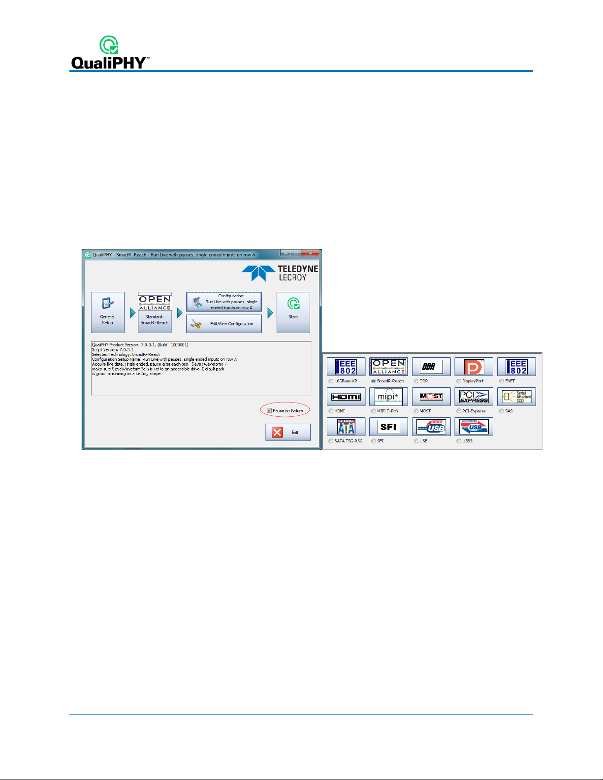
3. From the QualiPHY main window (as follows), select Standard, then BroadR-Reach from the
pop-up menu (if not alr eady s elected) . If you check the Pause on Failure box (circled) QualiPHY
prompts to retry the measure whenever a test fails.
Figure 3 - QualiPHY main menu and compliance test Standard selection menu
continued
10 922533 Rev B
 Loading...