

Teledyne Q-Lite, Q-LiteE Installation And Operating Handbook
Issue 3.1.10, 14 March 2017
2017
EN 55022 - Class B
EN 55024
EN 60950
Teledyne Paradise Datacom Ltd. Teledyne Paradise Datacom LLC
2&3 The Matchyns, Rivenhall End, 328 Innovation Blvd.
Witham, Essex, CM8 3HA, England. State College, PA 16803, U.S.A.
Tel: +44(0)1376 515636 Tel: +1 814 238 3450
http://www.paradisedata.com
Copyright © 2013-2017 Teledyne Paradise Datacom Ltd. All rights reserved.
Q-Lite™ Satellite Modem
Installation and Operating Handbook

Q-Lite Satellite Modem Installation and Operating Handbook
ii
Table of Contents
Chapter 1 Welcome ................................................................................................ 1-1
Chapter 2 About This Handbook ........................................................................... 2-1
2.1 Conventions ....................................................................................................... 2-1
2.2 Trademarks ........................................................................................................ 2-1
2.3 Disclaimer ........................................................................................................... 2-1
Chapter 3 Safety and Compliance Information .................................................... 3-1
3.1 Safety Compliance ............................................................................................. 3-1
3.2 Environmental Compliance ................................................................................. 3-2
3.3 Electromagnetic Compatibility (EMC) Compliance .............................................. 3-3
Chapter 4 Installation ............................................................................................. 4-1
4.1 Unpacking .......................................................................................................... 4-1
4.2 Line Supply ......................................................................................................... 4-1
4.3 Mounting in an Enclosure ................................................................................... 4-1
4.4 Getting Started ................................................................................................... 4-2
4.5 Enclosure Design Guidelines .............................................................................. 4-2
4.5.1 Temperature Warnings and Alarms ................................................................ 4-3
Chapter 5 Introduction ........................................................................................... 5-1
5.1 Overview ............................................................................................................ 5-1
5.2 Standard-Fit Hardware ....................................................................................... 5-2
5.2.1 L-band Operation ............................................................................................ 5-2
5.2.2 Ethernet Operation ......................................................................................... 5-2
5.3 Hardware Options ............................................................................................... 5-2
5.3.1 Terrestrial Interface Option Cards ................................................................... 5-2
5.3.1.1 G.703 Option Card .................................................................................. 5-2
5.3.1.2 EIA-530 Option Card ............................................................................... 5-3
5.3.1.3 IDR Option Card ..................................................................................... 5-3
5.3.1.4 LVDS Option Card .................................................................................. 5-3
5.3.1.5 HSSI Option Card ................................................................................... 5-3
5.3.1.6 Quad E1 Option Card .............................................................................. 5-3
5.3.2 Other Option Cards ......................................................................................... 5-4
5.3.3 BUC Power Supply Options ............................................................................ 5-4
5.4 Software Options ................................................................................................ 5-4
5.5 Optional Front Panel ........................................................................................... 5-8
5.5.1 Status Indicators ............................................................................................. 5-8
5.5.2 LCD Display .................................................................................................... 5-9
5.5.2.1 Keypad .................................................................................................... 5-9
5.6 Q-Lite™ Circuit Board Connectors .................................................................... 5-10
5.7 Utilities Card Connectors .................................................................................. 5-13
Chapter 6 User Interfaces ...................................................................................... 6-1
6.1 User Control ....................................................................................................... 6-1

Q-Lite Satellite Modem Installation and Operating Handbook
iii
6.1.1 Local Mode ..................................................................................................... 6-1
6.1.2 Takeaway Mode ............................................................................................. 6-1
6.2 Web User Interface ............................................................................................. 6-2
6.2.1 Login Screen .................................................................................................. 6-2
6.2.2 Status Screen ................................................................................................. 6-3
6.2.2.1 Status Setup ........................................................................................... 6-5
6.2.2.2 Status Demodulator ................................................................................ 6-6
6.2.2.3 Status Paired Carrier™ ........................................................................... 6-7
6.2.2.4 Status ACM ............................................................................................. 6-7
6.2.2.5 Status AUPC ........................................................................................... 6-8
6.2.2.6 Status BUC ............................................................................................. 6-8
6.2.3 Edit Screen ..................................................................................................... 6-8
6.2.4 Edit->Tx-Rx->Service Screen ......................................................................... 6-9
6.2.4.1 Terrestrial Interface ............................................................................... 6-10
6.2.4.2 Rx Values Track Tx ............................................................................... 6-10
6.2.4.3 Tx/Rx Service ........................................................................................ 6-10
6.2.4.4 Tx/Rx Rate Control ................................................................................ 6-12
6.2.4.5 Tx/Rx Data Rate ................................................................................... 6-13
6.2.4.6 Tx/Rx Symbol Rate ............................................................................... 6-13
6.2.4.7 Tx Clock Source .................................................................................... 6-14
6.2.4.8 Rx Clock Source ................................................................................... 6-14
6.2.4.9 Tx/Rx FEC Type ................................................................................... 6-15
6.2.4.10 Tx/Rx Modulation .............................................................................. 6-15
6.2.4.11 Tx/Rx FEC Code Rate ....................................................................... 6-15
6.2.4.12 Tx/Rx Frequency Band ...................................................................... 6-17
6.2.4.13 Tx/Rx Carrier Frequency ................................................................... 6-17
6.2.4.14 Tx/Rx Spectral Roll-off ...................................................................... 6-17
6.2.4.15 Tx/Rx Spectral Inversion ................................................................... 6-18
6.2.4.16 L-band Output Power ........................................................................ 6-18
6.2.4.17 Modem/BUC Carrier .......................................................................... 6-18
6.2.5 Edit->Tx-Rx->Service->Advanced Screen .................................................... 6-18
6.2.5.1 FastLink™ Optimisation Mode .............................................................. 6-19
6.2.5.2 DVB-S2 Tx/Rx Pilot Tones .................................................................... 6-19
6.2.5.3 DVB-S2/S2X Tx/Rx Frame Size ............................................................ 6-20
6.2.5.4 Sweep Mode ......................................................................................... 6-20
6.2.5.5 Sweep Width ......................................................................................... 6-20
6.2.5.6 Acknowledge Power Break ................................................................... 6-20
6.2.1 Edit->Tx-Rx->Advanced Timeslot Screens ................................................... 6-21
6.2.2 Edit->Tx-Rx->Framing Screen ...................................................................... 6-21
6.2.3 Edit->Tx-Rx->AUPC Screen ......................................................................... 6-21
6.2.3.1 AUPC Mode .......................................................................................... 6-21
6.2.3.2 Target Remote Eb/No ........................................................................... 6-22
6.2.3.3 Maximum AUPC Power Offset .............................................................. 6-22
6.2.3.4 Maximum Negative AUPC Power Offset ............................................... 6-22
6.2.3.5 AUPC Method ....................................................................................... 6-22
6.2.3.6 Carrier Loss Action ................................................................................ 6-23
6.2.3.7 Local Demod Unlocked Action .............................................................. 6-23
6.2.4 Edit->Tx-Rx->BUC/LNB Screen .................................................................... 6-24
6.2.4.1 BUC Interface ....................................................................................... 6-24
6.2.4.2 BUC LO Frequency ............................................................................... 6-24
6.2.4.3 BUC Attenuation ................................................................................... 6-25
6.2.4.4 DC to BUC ............................................................................................ 6-25

Q-Lite Satellite Modem Installation and Operating Handbook
iv
6.2.4.5 10MHz to BUC ...................................................................................... 6-25
6.2.4.6 Mute BUC Services in Standby ............................................................. 6-25
6.2.4.7 LNB Type .............................................................................................. 6-26
6.2.4.8 LNB LO Frequency ............................................................................... 6-26
6.2.4.9 DC to LNB ............................................................................................. 6-26
6.2.4.10 10MHz to LNB ................................................................................... 6-26
6.2.4.11 Mute LNB Services in Standby .......................................................... 6-27
6.2.5 Edit->Unit Screen ......................................................................................... 6-27
6.2.6 Edit->Unit->M&C Screen .............................................................................. 6-27
6.2.6.1 Modem Control and Passwords ............................................................ 6-28
6.2.6.2 RADIUS Server IP Address and Fallback Address ................................ 6-29
6.2.6.3 RADIUS Shared Secret ......................................................................... 6-29
6.2.6.4 RADIUS Authentication Validity............................................................. 6-30
6.2.6.5 RADIUS Server Timeout ....................................................................... 6-31
6.2.6.6 Remote M&C Interface .......................................................................... 6-31
6.2.6.7 Modem Identity ..................................................................................... 6-33
6.2.6.8 Submit Mode ......................................................................................... 6-33
6.2.7 Edit->Unit->M&C->SNMP Screen ................................................................. 6-34
6.2.8 Edit->Unit->M&C->Email Screen .................................................................. 6-35
6.2.9 Edit->Unit->M&C->HTTPS Screen ................................................................ 6-38
6.2.10 Edit->Unit->Alarms Screen ....................................................................... 6-39
6.2.10.1 LinkGuard™ Interference .................................................................. 6-39
6.2.10.2 Tx/Rx AIS Alarm Action ..................................................................... 6-39
6.2.10.3 Local/Remote Eb/No Alarm Threshold .............................................. 6-40
6.2.10.4 Buffer Slip Alarm Threshold ............................................................... 6-40
6.2.10.5 BUC DC Current Alarm ..................................................................... 6-40
6.2.10.6 Ethernet Port Down Alarms ............................................................... 6-41
6.2.11 Edit->Unit->Station Clock Screen .............................................................. 6-41
6.2.11.1 Station Clock Source ......................................................................... 6-41
6.2.11.2 Station Clock Frequency ................................................................... 6-42
6.2.11.3 Locking the High-Stability Oscillator to the Station Clock ................... 6-42
6.2.12 Edit->Unit->SAF Screen ............................................................................ 6-42
6.2.13 Edit->Unit->Upgrade Screen ..................................................................... 6-43
6.2.14 Edit->Unit->Miscellaneous->Time Screen ................................................. 6-47
6.2.1 Edit->Unit->Miscellaneous->Reset Screen ................................................... 6-47
6.2.1 Edit->Unit->Miscellaneous->NTP Screen ...................................................... 6-48
6.2.2 Edit->Unit->Carrier ID Screen ....................................................................... 6-48
6.2.2.1 Carrier ID Global Unique Identifier ........................................................ 6-49
6.2.2.2 Carrier ID Latitude and Longitude ......................................................... 6-49
6.2.2.3 Carrier ID Custom Message and Telephone Number ............................ 6-49
6.2.2.4 Carrier ID .............................................................................................. 6-49
6.2.3 Edit->IP Screen ............................................................................................ 6-50
6.2.3.1 IP Mode ................................................................................................ 6-50
6.2.3.2 Bridge M&C........................................................................................... 6-53
6.2.3.3 TCP Accleration .................................................................................... 6-53
6.2.3.4 Round-trip Satellite Delay...................................................................... 6-54
6.2.3.5 Header Compression ............................................................................ 6-54
6.2.3.6 Payload Compression ........................................................................... 6-54
6.2.3.7 ACM Mode ............................................................................................ 6-55
6.2.3.8 ACM Rain Fade Margin ......................................................................... 6-56
6.2.3.9 M&C IP Address, Subnet Mask & Modem IP Gateway .......................... 6-56
6.2.3.10 Traffic/Satelite IP Addresses and Subnet Masks ............................... 6-57

Q-Lite Satellite Modem Installation and Operating Handbook
v
6.2.3.11 IP Encapsulation Type ...................................................................... 6-58
6.2.3.12 Encapsulation PID ............................................................................. 6-58
6.2.3.13 MPE MAC Address ........................................................................... 6-59
6.2.3.14 Weighted QoS ................................................................................... 6-59
6.2.3.15 Ethernet Speed/Duplex ..................................................................... 6-60
6.2.3.16 IPv4/IPv6 Mode ................................................................................. 6-61
6.2.3.17 Ethernet MTU .................................................................................... 6-61
6.2.3.18 M&C VLAN ........................................................................................ 6-61
6.2.4 Edit->IP->Advanced Screen.......................................................................... 6-62
6.2.4.1 Terrestrial Buffer Size ........................................................................... 6-64
6.2.4.2 Satellite Buffer Size ............................................................................... 6-64
6.2.4.3 Active Queue Management ................................................................... 6-64
6.2.4.4 Ethernet DHCP Server .......................................................................... 6-66
6.2.4.5 Enable NAT........................................................................................... 6-66
6.2.4.6 DHCP Server Start/End Addresses and Traffic IP Address ................... 6-66
6.2.4.7 DNS IP Address .................................................................................... 6-66
6.2.4.8 Ethernet Address Learning .................................................................... 6-66
6.2.4.9 Web Acceleration .................................................................................. 6-67
6.2.4.10 DNS IP Address ................................................................................ 6-67
6.2.4.11 Enable Dynamic Routing ................................................................... 6-67
6.2.4.12 sFlow Metrics Collection .................................................................... 6-68
6.2.4.13 Null Packet Insertion ......................................................................... 6-68
6.2.4.14 PCR Restamping .............................................................................. 6-69
6.2.4.15 MPEG Over IP Type .......................................................................... 6-69
6.2.4.16 TS Data Rate and Nominal De-jitter Buffer Delay .............................. 6-69
6.2.4.17 Destination Address and Destination Port ......................................... 6-70
6.2.4.18 Local Multicast Address and Local Port ............................................. 6-70
6.2.4.19 Stream Tx/Rx Terrestrial Interface ..................................................... 6-71
6.2.4.20 Stream Tx/Rx Identifier ...................................................................... 6-71
6.2.4.21 Stream Tx Data Rate ......................................................................... 6-71
6.2.4.22 Stream Tx Modulation ....................................................................... 6-71
6.2.4.23 Stream Tx FEC Code Rate ................................................................ 6-72
6.2.4.24 Stream Tx Pilot Tones ....................................................................... 6-72
6.2.4.25 Stream Tx Frame Size ...................................................................... 6-73
6.2.4.26 Tx/Rx Symbol Rate ........................................................................... 6-73
6.2.4.27 Point-to-multipoint Operation ............................................................. 6-73
6.2.4.28 VLAN Filtering ................................................................................... 6-74
6.2.4.29 Download Root Authority Security Certificate .................................... 6-75
6.2.5 Edit->IP->QoS Screen .................................................................................. 6-75
6.2.6 Edit->IP->Static Routes Screen .................................................................... 6-75
6.2.7 Edit->IP->Header Compression Routes Screen ............................................ 6-77
6.2.8 Edit->Paired Carrier Screen .......................................................................... 6-78
6.2.8.1 Paired Carrier Enable ............................................................................ 6-78
6.2.8.2 Round-trip Delay ................................................................................... 6-81
6.2.8.3 Satellite Longitude................................................................................. 6-82
6.2.8.4 Earth Station Longitude ......................................................................... 6-82
6.2.8.5 Earth Station Latitude ............................................................................ 6-82
6.2.8.6 Minimum Round-trip Delay .................................................................... 6-83
6.2.8.7 Maximum Round-trip Delay ................................................................... 6-83
6.2.9 Edit->Memories Screen ................................................................................ 6-83
6.2.9.1 Edit->Memories->Recall Screen ............................................................ 6-84
6.2.9.2 Edit->Memories->Recall->Advanced Reversionary Control Screen....... 6-84

Q-Lite Satellite Modem Installation and Operating Handbook
vi
6.2.9.3 Edit->Memories->Store Screen ............................................................. 6-86
6.2.9.4 Edit->Memories->Download Screen ...................................................... 6-86
6.2.9.5 Edit->Memories->Upload Screen .......................................................... 6-87
6.2.10 Edit->Redundancy Screen ........................................................................ 6-87
6.2.11 ClearLinQ™ Tx Adaptive Predistorter Screens ......................................... 6-89
6.2.12 View Screen .............................................................................................. 6-91
6.2.12.1 Rx Spectrum Monitor ......................................................................... 6-92
6.2.12.2 Rx Constellaton Monitor .................................................................... 6-94
6.2.12.3 IP Graphs .......................................................................................... 6-97
6.2.12.4 Other Time-based Graphs ................................................................. 6-99
6.2.12.5 Alarms ............................................................................................. 6-100
6.2.12.6 System Log ..................................................................................... 6-101
6.2.12.7 View->Setup Screen ....................................................................... 6-101
6.2.12.8 View->Unit Screen .......................................................................... 6-102
6.2.12.9 View->SAF Screen .......................................................................... 6-103
6.2.13 Test Screen ............................................................................................ 6-104
6.2.14 BER Test ................................................................................................ 6-105
6.2.15 IP Test Features ..................................................................................... 6-107
6.3 Front-panel Interface ...................................................................................... 6-109
6.3.1 Keypad Operation ....................................................................................... 6-109
6.3.1.1 Cursor ................................................................................................. 6-109
6.3.1.2 Navigation Keys .................................................................................. 6-109
6.3.1.3 Alphanumeric Keys ............................................................................. 6-110
6.3.1.4 Special Function Keys ......................................................................... 6-110
6.3.2 LCD Screen Layout .................................................................................... 6-111
6.4 Front Panel Menu Structure ............................................................................ 6-112
6.4.1 Main Menu .................................................................................................. 6-112
6.4.2 Status Menu ............................................................................................... 6-113
6.4.3 Edit Menu ................................................................................................... 6-114
6.4.3.1 Edit->Tx Menu .................................................................................... 6-115
6.4.3.2 Edit->Rx Menu .................................................................................... 6-116
6.4.3.3 Edit->Unit Menu .................................................................................. 6-117
6.4.4 View Menu .................................................................................................. 6-118
6.4.5 Test Menu ................................................................................................... 6-118
Chapter 7 Modem Concepts .................................................................................. 7-1
7.1 System Clocking ................................................................................................. 7-1
7.1.1 Transmit Clocking ........................................................................................... 7-2
7.1.1.1 Internal Clock .......................................................................................... 7-2
7.1.1.2 Tx Clock In .............................................................................................. 7-2
7.1.1.3 Receive Reference.................................................................................. 7-3
7.1.2 Receive Clocking ............................................................................................ 7-4
7.1.2.1 Satellite ................................................................................................... 7-4
7.1.2.2 Tx Clock In .............................................................................................. 7-4
7.1.2.3 Station Clock ........................................................................................... 7-5
7.1.2.4 Internal Clock .......................................................................................... 7-6
7.1.3 Guidelines for Clocking Configuration ............................................................. 7-6
7.1.3.1 Clock Loop at One End ............................................................................ 7-6
7.1.3.2 No Clock Loop ......................................................................................... 7-7
7.1.3.3 Determining Buffer Size .......................................................................... 7-7
7.1.3.4 G.703 Clock Extension ............................................................................ 7-8
7.2 Automatic Uplink Power Control ......................................................................... 7-8

Q-Lite Satellite Modem Installation and Operating Handbook
vii
7.2.1 Introduction ..................................................................................................... 7-8
7.2.2 Configuring AUPC .......................................................................................... 7-9
7.3 1:1 Redundancy Operation ............................................................................... 7-10
7.3.1 Overview....................................................................................................... 7-10
7.3.2 Switching Operation ...................................................................................... 7-10
7.3.3 Setup Procedure ........................................................................................... 7-11
7.3.4 IP Addressing and Operation in Redundancy Configurations ........................ 7-11
7.3.4.1 1:1 IP Operation .................................................................................... 7-11
7.3.4.2 1:N IP Operation ................................................................................... 7-12
7.4 Software Activated Features ............................................................................. 7-12
7.5 Software Upgrading .......................................................................................... 7-13
7.6 LinkGuard™ Interference Detection .................................................................. 7-14
7.7 FastLink Low-latency LDPC .............................................................................. 7-15
7.8 IP Functionality ................................................................................................. 7-17
7.8.1 Base Modem IP ............................................................................................ 7-17
7.8.2 IP Addressing ............................................................................................... 7-18
7.8.2.1 Gateways .............................................................................................. 7-18
7.8.3 Throughput Performance .............................................................................. 7-18
7.8.4 Jumbo Ethernet Frame Support .................................................................... 7-18
7.8.5 M&C VLAN ................................................................................................... 7-18
7.8.6 IP Over ESC ................................................................................................. 7-19
7.8.7 IP Interoperability .......................................................................................... 7-20
7.8.8 IP Connectivity Modes .................................................................................. 7-20
7.8.9 TCP Acceleration .......................................................................................... 7-20
7.8.10 Traffic Shaping .......................................................................................... 7-21
7.8.10.1 Guaranteed Bandwidth ...................................................................... 7-21
7.8.10.2 Maximum Bandwidth ......................................................................... 7-22
7.8.10.3 Priority ............................................................................................... 7-22
7.8.10.4 Stream Classification ......................................................................... 7-22
7.8.10.5 Traffic Shaping Graphs ..................................................................... 7-27
7.8.11 Static and Dynamic Routing ...................................................................... 7-28
7.8.12 Header Compression ................................................................................ 7-28
7.8.13 VLAN Operation ........................................................................................ 7-29
7.8.14 Adaptive Coding and Modulation (ACM) ................................................... 7-30
7.9 DVB-S2X, DVB-S2 and SmartLink .................................................................... 7-32
7.10 Paired Carrier™ ................................................................................................ 7-35
7.11 Antenna Control ................................................................................................ 7-39
7.12 Beacon Receiver .............................................................................................. 7-41
7.13 Point-to-multipoint Interoperation with Q-MultiFlex ............................................ 7-43
Chapter 8 Remote Control Protocol ...................................................................... 8-1
Chapter 9 Data Interfaces ...................................................................................... 9-1
Chapter 10 Connector Pinouts .............................................................................. 10-1
Chapter 11 Fault Messages ................................................................................... 11-1
11.1 Transmit Faults ................................................................................................. 11-2
11.2 Transmit Warnings ........................................................................................... 11-4
11.3 Receive Faults .................................................................................................. 11-5
11.4 Receive Warnings ............................................................................................ 11-7

Q-Lite Satellite Modem Installation and Operating Handbook
viii
11.5 Unit Faults ........................................................................................................ 11-9
11.6 Unit Warnings ................................................................................................. 11-10
11.7 Start-up Problems ........................................................................................... 11-10
Chapter 12 Specification Summary ...................................................................... 12-1
12.1 Common Main Specifications ........................................................................... 12-1
12.2 Tx Modulator Specifications .............................................................................. 12-3
12.3 Rx Demodulator Specifications ......................................................................... 12-4
12.4 Clocking and Buffering Specifications ............................................................... 12-4
12.5 Framing and Deframing Specifications ............................................................. 12-5
12.6 Drop and Insert Option Specifications ............................................................... 12-5
12.7 Extended Drop and Insert Option Specifications ............................................... 12-6
12.8 BERT Option Specifications .............................................................................. 12-6
12.9 AUPC Specifications......................................................................................... 12-6
12.10 Traffic Log Specifications .............................................................................. 12-7
12.11 Common Specifications ................................................................................ 12-7
12.12 Internet Traffic .............................................................................................. 12-8
12.13 BUC / LNB facilities ...................................................................................... 12-8
12.14 FEC BER/PER Performance......................................................................... 12-9
12.14.1 DVB-S2/S2X ........................................................................................... 12-10
12.14.2 FastLink .................................................................................................. 12-14
12.14.3 TPC ........................................................................................................ 12-14
12.14.4 DVB-S/DSNG ......................................................................................... 12-15
12.15 FEC Minimum/Maximum Data Rates .......................................................... 12-16
Chapter 13 Glossary .............................................................................................. 13-1
Chapter 14 Technical Support ............................................................................... 14-1
Q-Lite Satellite Modem Installation and Operating Handbook
1-1
Chapter 1 Welcome
Figure 1-1 Q-Lite™ Advanced COTM Satellite Modem
The Q-Lite™ satellite modem (Figure 1-1) embodies a new concept in satellite modem
technology: a compact, state-of-the-art software-defined modem that can be easily
integrated into custom enclosures for comms-on-the-move and portable satellite
communication systems.
The Q-Lite™ L-band modem has a powerful processor that is ideal for handling IP traffic.
In common with other Q Series modems, it incorporates a software suite called XStream
IP™. This has been created in response to a perceived widespread dissatisfaction in the
industry with the usability and quality of service provided by IP-over-satellite in general.
Paradise has re-engineered every aspect of IP support from the ground up to ensure
ease of use, a high degree of integration between features and outstanding performance
and efficiency.
Specifically:
• XStream IP™ is the most advanced integrated suite of IP optimisation and traffic
management features available in any satellite modem.
• XStream IP™ is specifically optimised to be highly efficient and reliable over satellite.
• XStream IP™ provides 150,000 packets-per-second processing capability for
lightning-fast IP throughput.
• XStream IP™ is simple to set up and use.

Q-Lite Satellite Modem Installation and Operating Handbook
1-2
• XStream IP™ includes all IP features as standard making it very good value.
The design aim for Paradise’s Q Series modems, of which the Q-Lite™ is one, was to
create the industrys most versatile and bandwidth-efficient satellite modem. Among the
satellite band-width saving features available are:
• Paired Carrier™, allowing two carriers to be overlapped in the space segment,
saving up to 50% bandwidth.
• DVB-S2 and DVBS2X state-of-the-art Forward Error Correction (FEC)
representing the most bandwidth-efficient FEC technology available.
• Spectral roll-off factors down to 5%, saving up to 15% bandwidth compared
with 20% roll-off.
• IP compression, saving up to 50% bandwidth.
• Adaptive Coding and Modulation (ACM), saving up to 50% bandwidth.
• TCP Acceleration, enabling up to 93% bandwidth utilization for TCP traffic.
• ClearLinq™ Tx adaptive pre-distorter, providing up to 2dB compensation for
linear and non-linear distortion in the channel.
• 9-tap Rx equaliser, providing compensation for linear distortion in the channel,
such as from group delay. The equaliser is automatically switched on in all
modes of operation above 10Msps.
New levels of usability are provided by a leading set of built-in diagnostic tools including
spectrum and constellation monitors that facilitate the detection of any link degradation. In
addition, LinkGuard™ (U.S. patent 8351495) monitors underneath the received carrier
for any interference, while on traffic.
The Q-Lite™ modem is backwards compatible with all Quantum and Evolution series
modems.
DVB-S2X, the successor to DVB-S2, is the most efficient and robust coding and
modulation standard available for satellite transmission.
Although the Q-Lite™ is primarily used for IP links, Paradise’s SmartLink™ technology
allows non-packetized continuous traffic, such as EIA-530 traffic, to also be used with
DVB-S2. The Q-Lite™ therefore provides a painless migration path to newer, more
efficient communications technology while fully supporting legacy services.
FastLink™ Low-Density Parity-Check (LDPC) Forward Error Correction (FEC) combines
high coding gain with low latency. FastLink™ can therefore be used to replace both
conventional LDPC (which has high latency) and Turbo Product Code FEC (which has a
lower coding gain).
Paired Carrier™ allows space segment reuse. It overlays transmit and receive carriers in
the same space segment reducing satellite bandwidth requirements by up to 50%. It can
be used in addition to, not instead of, other bandwidth saving techniques. It incorporates
ViaSat’s patented PCMA technology, which is protected under U.S. patent numbers
5,596,439, 6,011,952 and 6,725,017.
This handbook will guide you through the process of installing and using your Q-Lite™
satellite modem.

Q-Lite Satellite Modem Installation and Operating Handbook
1-3
Redundancy Switch operation is documented separately – see ‘Installation and Operating
Handbook for Q Series Redundancy Switches’.

Q-Lite Satellite Modem Installation and Operating Handbook
2-1
Chapter 2 About This Handbook
2.1 Conventions
This warning symbol is intended to alert the user to the presence
of a hazard that may cause death or serious injury.
This information symbol is intended to alert the user to the
presence of important operating instructions critical to correct
system function.
2.2 Trademarks
All trademarks used in this handbook are acknowledged to be the property of their
respective owners.
2.3 Disclaimer
Although every effort is made to ensure the accuracy and completeness of the
information in this handbook, this cannot be guaranteed and the information contained
herein does not constitute a product warranty. A separate product warranty statement is
available. Teledyne Paradise Datacom maintains a programme of continuous product
improvement and reserves the right to change specifications without prior notice.

Q-Lite Satellite Modem Installation and Operating Handbook
3-1
Chapter 3 Safety and Compliance Information
PLEASE READ THE FOLLOWING INFORMATION BEFORE
INSTALLATION AND USE.
3.1 Safety Compliance
To ensure operator safety, this satellite modem conforms to the provisions of EMC Low
Voltage Directive 2006/95/EC and complies with the following standard:
• EN 60950-1:2006 ‘Safety of Information Technology Equipment, Including
Electrical Business Equipment’.
Prior to installation and at all points during operation the following points must be
observed.
This satellite modem requires the use of a regulated 24V power
supply that provides a line conductor and ground connection. The
power system must have a direct ground connection.

Q-Lite Satellite Modem Installation and Operating Handbook
3-2
3.2 Environmental Compliance
All Teledyne Paradise Datacom satellite modem products are compliant with the following
EC environmental directives:
• The Reduction of Hazardous Substances (RoHS) Directive 2011/65/EU.
• The Waste Electrical and Electronic Equipment (WEEE) Directive 2012/19/EU.
The equipment should not be directly connected to the Public Telecommunications
Network.
Operation of the equipment in an environment other than that stated will invalidate the
safety standards.
The equipment must not be operated in an environment in which it
is exposed to:
• Unpressurised altitudes greater than 6000 metres.
• Extreme temperatures outside the stated operating range.
• Excessive dust.
• Moisture or humid atmosphere above 95% relative
humidity.
• Excessive vibration.
• Flammable gases.
• Corrosive or explosive atmosphere.

Q-Lite Satellite Modem Installation and Operating Handbook
3-3
3.3 Electromagnetic Compatibility (EMC) Compliance
This satellite modem conforms to the provisions of EMC Directive 2004/108/EC and
complies with the following EC and FCC standards:
• Emissions: EN 55022:2010 Class B – ‘Information Technology Equipment –
Radio Disturbance Characteristics – Limits and Methods of Measurement’.
• Immunity: EN 55024:2010 (incorporating EN61000-4-2:2009; EN61000-43:2006, A1, A2; EN61000-4-4:2012; EN61000-4-6:2009) – ‘Information
Technology Equipment – Immunity Characteristics – Limits and Methods of
Measurement ’.
• Federal Communications Commission (FCC) Federal Code of Regulation Part
15, Subpart B.
All D-type connectors must have grounding fingers on the plug shell to guarantee
continuous shielding. The back-shells must comply with the requirements of VDE 0871
and FCC 20708, providing at least 40dB of attenuation from 30MHz to 1GHz. A good
quality cable with a continuous outer shield, correctly grounded, must be used.
Connections to transmit and receive IF interfaces must be made with double-screened
coaxial cable (for example, RG223/U).
The modem Ethernet ports should not be connected directly to outdoor Ethernet cables
that may be be subject to transient overvoltages due to atmospheric discharges and
faults in the power distribution network. Instead, the modem should be connected via an
Ethernet switch or router to provide isolation from overvoltages as recommended in
clause 6 of EN 60950-1.

Q-Lite Satellite Modem Installation and Operating Handbook
4-1
Chapter 4 Installation
4.1 Unpacking
Prior to unpacking, inspect the exterior of the shipping container for any sign of damage
during transit. If damage is evident, contact the carrier immediately and submit a damage
report.
Carefully unpack all items, taking care not to discard any packing materials. Should the
unit need to be returned to Teledyne Paradise Datacom then you should use the original
packing carton as it is designed to provide the necessary level of protection during
shipment.
Once unpacked, visually inspect the contents to ensure all parts are present and that
there is no visible damage. Other than the unit itself, the shipping container should
contain a power cord and a Quick Start Guide.
4.2 Line Supply
This satellite modem is classified by the EN 60950-1 safety standard as a ‘Pluggable
Equipment Type A’. A regulated 24V DC power supply must be used. The power supply
connector on the Q-Lite™ allows for a second power supply to be connected in parallel in
order to provide protection against the failure of a single supply. Typical power
consumption is 25W; maximum power consumption is 33W.
No power supply or power cord is provided.
The installation of the satellite modem and the connection to the power supply must be
made in compliance with local and national wiring regulations for a Category II ‘impulse
over-voltage’ installation. The satellite modem should be positioned to allow a convenient
means of disconnection from the line supply.
4.3 Mounting in an Enclosure
The unit is shipped with an optional L-bracket that may be useful for any preliminary testing
of the unit prior to installation in its final enclosure, at which point the L-bracket would
normally be removed.
When designing an enclosure, it should be ensured that adequate ventilation and cooling
are provided. One fan connector is provided as standard and a second fan connector is
available on the optional Utilities Card.

Q-Lite Satellite Modem Installation and Operating Handbook
4-2
4.4 Getting Started
Connect the appropriate cables to the transmit and receive L-band TNC connectors, along
with the cable for the traffic interface. If a front-panel keypad membrane and LCD display
have been provided then connect the cables for both of these to the appropriate Q-Lite™
connectors.
Power the unit and wait for it to complete its initialization when it will display summary
status information.
From the front-panel menu, select Main->Edit->All in order to set the configuration prior to
operation.
It is also possible to set up the unit from a web browser as described in Section 7.4.
When setting up a number of units that have similar configurations, the configuration
settings of one unit can be saved, extracted and then transferred to each of the other
units in turn. This procedure is explained in Section 7.4.3.
Getting started is covered in more detail in the Q-Lite™ modem Quick Start Guide
(provided with the unit).
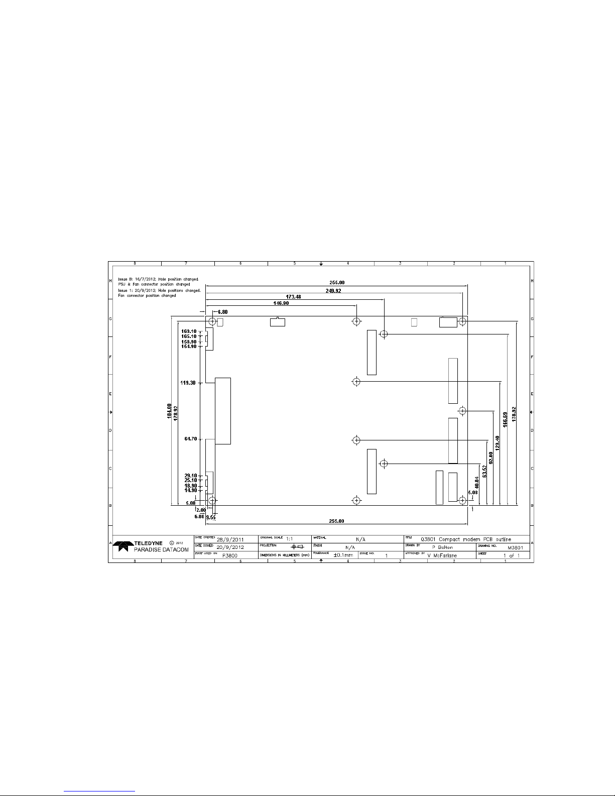
4.5 Enclosure Design Guidelines
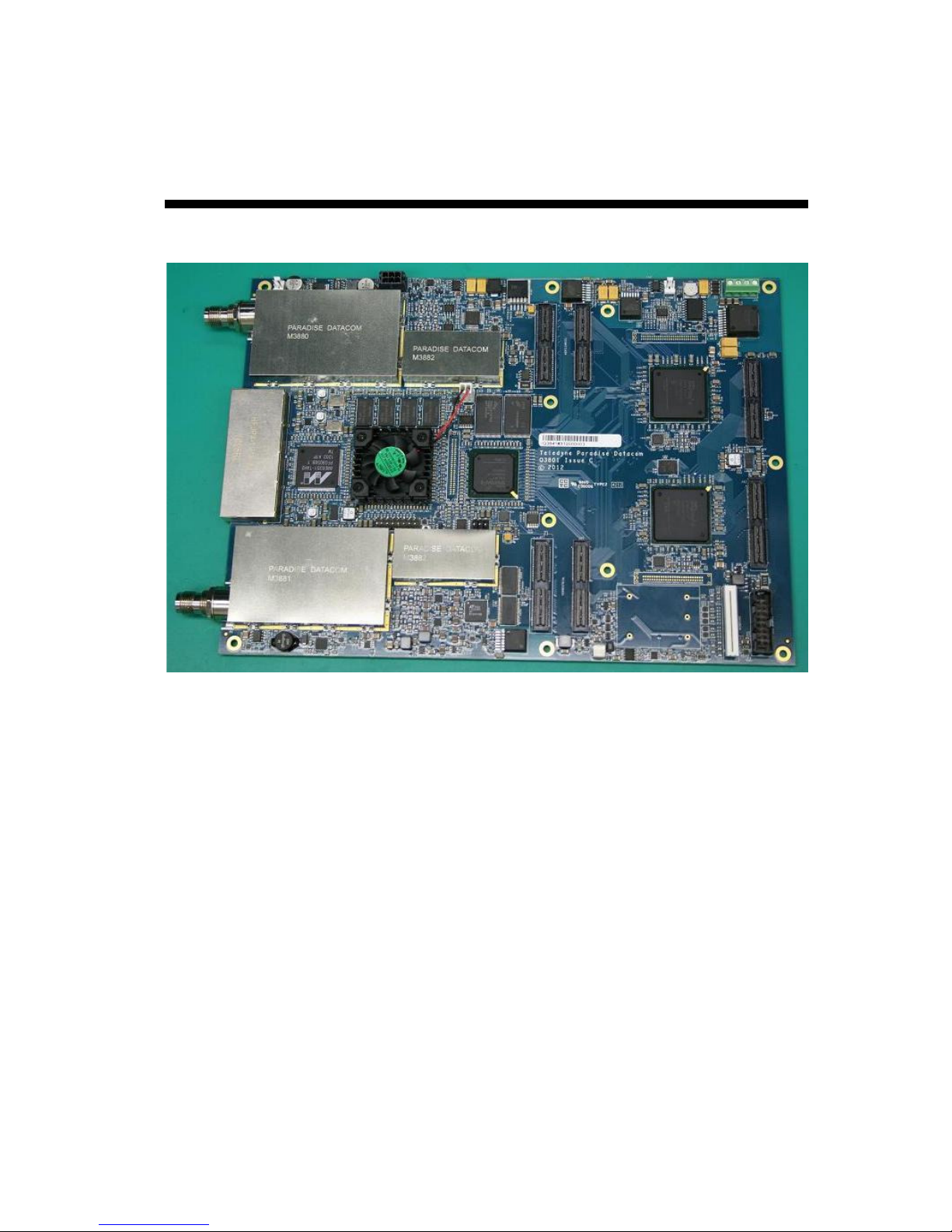
The dimensions for the Q-Lite™ circuit board are shown in Figure 4-1. A higher
resolution drawing of the circuit board dimensions is available on request from Technical
Support.
The circuit board, as supplied, is suitable for incorporation into enclosures that mount the
board to a metal chassis and employ fans to move air out of the box. Power supply
regulation devices dissipate heat via the circuit-board mounting holes, which need to be
attached to a metal plate or chassis. Other devices dissipate heat into the enclosure and
and this typically will need to be expelled by a fan in the enclosure. The microprocessor
has its own fan to move heat away from the device locally.
The modem operating temperature range is -40°C to +85°C. Temperature warnings and
alarms, which have implications for the design of the cooling for the enclosure, are
discussed in the next section.
It is possible to design an enclosure that does not have fans to remove heat. A heatsink
can be used to remove heat from any of the devices on the top of the board and the
mounting holes. Any such design could replace the microprocessor fan or it can be
retained if the design can make use of it. Any heatsink can itself be cooled by fans if
required. Thermal profile information for the board is available from Technical Support if
needed.
As measured from the top side of the circuit board, the highest component heights are as
follows:
Q-Lite Satellite Modem Installation and Operating Handbook
4-3
• With no mezzanine, terrestrial or Utilities cards fitted: 13mm. This is due to the
10MHz external oscillator, which could potentially be removed after which the
heighest component is 8mm.
• With a mezzanine card (for DVB-S2, FastLink™ or Paired Carrier™) fitted:
13mm.
• With a terrestrial interface card fitted: 30mm.
• With a Utilities card fitted: 32.5mm.
When fitted with the L-bracket provided by Paradise, a 5mm stand-off is used underneath
the board and this height (or the equivalent measurement for any replacement bracket)
needs to be added to give the total height.
Figure 4-1 Q-Lite™ Circuit Board Dimensions
4.5.1 Temperature Warnings and Alarms
The modem operating temperature range is -40°C to +85°C. Temperature is measured on
the surface of the main PCB, which will typically be hotter than the ambient temperature
inside the enclosure by around 20°C. It is the ambient temperature that is crucial to
correct operation, not the reported surface temperature. Consequently, operator warning
are raised at +94.5°C and below -12.1°C. Operator alarms are raised at -22.1°C and
+104.5°C. In other words, warnings are provided when within approximately 10 degrees
of the upper and lower temperature limits and alarms occur when the temperature
reaches the actual limits. By default, the transmit carrier is muted when a temperature

Q-Lite Satellite Modem Installation and Operating Handbook
4-4
alarm occurs due to the potential for the modem software to lose control over the
hardware and for erratic behavior to occur. The enclosure designer is responsible for
coping with any temperature rise in the enclosure relative to the ambient temperature
outside of the enclosure.

Q-Lite Satellite Modem Installation and Operating Handbook
5-1
Chapter 5 Introduction
5.1 Overview
The Q-Lite™ satellite modem is designed primarily for closed network operation in mobile
environments, providing a data link between geographically distant sites via satellite.
Features include:
• DVB-S2 (EN 302 307-1) and DVB-S2X (EN 302 307-2) operation including
Adaptive Coding and Modulation (ACM).
• L-band frequency range of 950MHz to 2050MHz.
• Closed network modes.
• Variable bidirectional data rates between 2.4kbps and 200Mbps.
• BPSK, QPSK, Offset QPSK, 8PSK, 8QAM, 16QAM, 16APSK, 32APSK, 64APSK
and 64QAM modulation schemes.
• Forward Error Correction (FEC) options of Turbo Product Code (TPC), FastLink
low-latency Low Density Parity Code (LDPC) and DVB-S2/S2X.
• Spectral roll-off factors of 5%, 10%, 15%, 20%, 25% and 35%.
• Terrestrial interfaces including Internet Protocol (IP), RS422, V.35 and RS232.
• Automatic Uplink Power Control (AUPC) automatically adjusts modem output
power to maintain a constant Eb/No at the distant end of the satellite link.
• Optional front-panel display and keypad for local control.
• Remote equipment can be controlled over the satellite via serial or IP traffic
interfaces. Remote modem control is supported via web browsing, the Simple
Network Management Protocol (SNMP), Telnet and the proprietary Paradise
Universal Protocol (PUP) command protocol.
• XStream IP™, providing an advanced integrated suite of IP optimisation and
traffic management features. These include Transport Control Protocol (TCP)
acceleration, header and payload compression, encryption, static and dynamic
routing, Dynamic Host Control Protocol (DHCP), IEEE 802.1p Quality of Service
(QoS) support, IEEE 802.1q VLAN support, traffic shaping and Adaptive Coding
and Modulation (ACM). A dual IPv4/IPv6 TCP/IP stack is provided. IPv4 support is
provided for all IP functions as the default. With respect to IPv6, bridging and
routing are supported along with an IPv6 embedded web server. Modem IP
addresses and static routes can also be entered and displayed in IPv6 format.
TCP acceleration is supported at up to the maximum data rate for the modem.
Up to 10000 concurrent accelerated TCP connections are supported along with up
to 40,000 unaccelerated TCP connections. Bandwidth utilization when TCP
acceleration is enabled is typically over 90%. Bridging, static routing and
dynamic routing (RIP V1 and V2, OSPF V2 and V3 and BGP V4) are all
supported. Ethernet, IP, User Datagram Protocol (UDP) and Real Time Protocol
(RTP) header compression are supported. The 14-byte Ethernet frame is
typically compressed to one byte. IP/UDP/RTP headers are typically compressed
to between one and three bytes. The one-way packet processing limit for header
compression is 60,000 packets per second (pps); the two-way limit is 45,000 pps.
IP/UDP/RTP header compression is compliant with the RFC 3095 (Robust Header
Compression) standard. IP payload compression is provided (compliant with the

Q-Lite Satellite Modem Installation and Operating Handbook
5-2
RFC 1951 ‘DEFLATE’ standard). This compresses TCP and UDP packet
payloads by typically 50%.
5.2 Standard-Fit Hardware
5.2.1 L-band Operation
The following are provided as standard:
• L-band operation, via transmit and receive L-band TNC-type connectors
(supporting 50Ω operation at 950 to 2050MHz).
• A high-stability L-band 10MHz reference signal for output to a Block Up Converter
(BUC) or Low-Noise Block (LNB) in order to phase-lock the BUC or LNB’s local
oscillator to a highly stable frequency reference.
5.2.2 Ethernet Operation
Four Gigabit Ethernet RJ45 connectors are fitted as standard. These can be used
concurrently for modem Monitor and Control (M&C) and satellite traffic. These provide a
combined 150,000 packets-per-second processing capability and data rates over satellite
of up to 200Mbps bidirectional.
Ethernet speed, duplex and cable termination (crossover versus straight-through) are
auto-negotiated. Speed and duplex can also be set to fixed values if desired.
5.3 Hardware Options
5.3.1 Terrestrial Interface Option Cards
One terrestrial interface card may be fitted. In addition, a four-port Ethernet switch for IP
is provided as standard.
The Q-Lite™ supports the same set of terrestrial interface cards as the Q-Flex™ modem
although not all of these are listed on the Q-Lite™ datasheet. If you have an application
that requires a terrestrial interface card that is not on the datasheet then then please
contact Sales or Technical Support.
5.3.1.1 G.703 Option Card
The G.703 option card (part number P3722) provides support for G.703 E1/T1, E2/T2 and
E3/T3 traffic rates. Unbalanced G.703 is provided on two BNC 75Ω sockets and balanced
G.703 is provided on two RJ45 sockets. For balanced operation, T1 line impedance is
100Ω, E1 line impedance is 120Ω and T2 line impedance is 110Ω. Unbalanced E1, T2, E3

Q-Lite Satellite Modem Installation and Operating Handbook
5-3
and T3 line impedance is 75Ω. Line impedance is software selectable. The following
software features are included as standard with the G.703 option card:
• G.703 clock extension, providing a high-stability reference clock over satellite
(alternative to GPS). In this mode the G.703 card is used purely as a high-stability
clock generator for some other traffic source, such as serial data.
• Timeslot Drop & Insert feature, allowing fractional E1/T1 services.
5.3.1.2 EIA-530 Option Card
The EIA-530 option card (part number P3720) provides selectable RS422, X.21, V.35 and
RS232 operation up to 10Mbps via a 25-way D-type female connector.
5.3.1.3 IDR Option Card
The Intermediate Data Rate (IDR) option card (part number P3721) provides an IESS
308-compliant IDR capability including two 32kbps ADPCM ESC audio channels, multiple
backward alarms support and independent ESC and Auxiliary ports. The connectivity is
via a 50-way D-type female connector.
The following software features are included as standard with the IDR option card:
• Advanced AUX feature providing variable rate synchronous Aux channel. This
includes the option to replace IDR audio channels with serial data.
• Audio option. This allows two audio streams in 64kbps or two audio and 64kbps
data in 128kbps.
5.3.1.4 LVDS Option Card
The Low Voltage Differential Signal (LVDS) option card (part number P3001) provides
LVDS at data rates of up to 60Mbps via a 25-way D-type female connector.
5.3.1.5 HSSI Option Card
The High Speed Serial Interface (HSSI) option card (part number P3705) provides HSSI
at data rates of up to 60Mbps via an industry-standard 50-way SCSI-2 DCE connector.
5.3.1.6 Quad E1 Option Card
The Quad E1 option card (part number P3706) supports four synchronous G.703 HDB3encoded balanced RJ45 ports. Along with full E1 bearers, Drop and Insert of up to 32
timeslots is provided on all four interfaces. The Quad E1 card and G.703 card are
compatible when used for a single full E1.
All data rates between 64kbps and 8448kbps are supported in multiples of 64kbps. The
data is multiplexed onto a single carrier using either an IBS frame format (with overhead
of 6.7%) or Closed Network frame format (with no overhead) or Closed Network + ESC

Q-Lite Satellite Modem Installation and Operating Handbook
5-4
frame format (with overhead of less than 0.5%). The absolute minimum amount of
bandwidth is used in all cases, in direct proportion to the required number of timeslots.
5.3.2 Other Option Cards
The following feature-specific option cards are available:
• P3609 DVB-S2/S2X option card.
• P3605 FastLink™ option card, required for FastLink™ low-latency Low-Density
Parity-Check (LDPC) Forward Error Correction (FEC) operation.
• P3607 Paired Carrier™ option card, required for Paired Carrier™ operation
(which overlays transmit and receive carriers in the same space segment reducing
the overall required satellite bandwidth).
5.3.3 BUC Power Supply Options
The Q-Lite™ satellite modem can be connected to a Power Supply Unit (PSU) for
powering a Block Up Converter (BUC). Refer to Table 5-1 for the available Paradise BUC
power supply options. The BUC PSU is a separate item from the satellite modem circuit
board and therefore space must also be assigned in any custom enclosure design for the
BUC PSU.
Part Number BUC PSU
Type
P3543 200W 48V output
A.C. in/D.C. out
P3544 200W 24V output
A.C. in/D.C. out
P3545 +/-48V input, 200W 48V output
D.C. in/D.C. out
P3546 +/-48V input, 200W 24V output
D.C. in/D.C. out
P3547 +48V input, 200W 48V output
D.C. in/D.C. out
Table 5-1 BUC Power Supply Options
5.4 Software Options
Several software options, known as Software Activated Features (SAF), are available as
shown in Table 5-2. These can be purchased on a pay-as-you-go basis and
retrospectively activated in deployed units as required. The SAF concept (including timelimited free access to most features) is explained in Section 8.5.
In the table, the SAF Code column lists the acronyms by which features are referred to on
the modem’s local user interface.
Feature
SAF
Code
Description
Transmit
TX Enables the Tx service.
Receive
RX Enables the Rx service.

Q-Lite Satellite Modem Installation and Operating Handbook
5-5
Terrestrial data rate
0 to 2048kbps
DR0 Enables data rates in the given range.
Terrestrial data rate
0 to 5Mbps
D1L Enables data rates in the given range.
Terrestrial data rate
0 to 10Mbps
D1H Enables data rates in the given range.
Terrestrial data rate
0 to 25Mbps
DR2 Enables data rates in the given range.
Terrestrial data rate
0 to 60Mbps
DR3 Enables data rates in the given range.
Terrestrial data rate
0 to 100Mbps
DR4 Enables data rates in the given range.
Terrestrial data rate
0 to 200Mbps
DR5 Enables data rates in the given range.
Table 5-2 Software Activated Features (continues over page)

Q-Lite Satellite Modem Installation and Operating Handbook
5-6
Feature
SAF
Code
Description
XStream IP
™
DVB-S2X
• IP-over-DVB encapsulation. Supports the
transmission of IP packets with/without Ethernet
frames over DVB-S2/DVB-S2X using Multiprotocol
Encapsulation (MPE) (EN 301 192), Unidirectional
Lightweight Encapsulation (ULE) (RFC 4326) and
Paradise XStream Encapsulation (PXE).
• ACM. Enables DVB-S2/DVB-S2X Adaptive Coding
and Modulation (ACM).
• VCM. Allows either two ASI streams, or one ASI
stream and one IP stream, to be multiplexed onto a
single carrier.
DVB-S2
X CCM
Tx
S2XT Enables DVB-S2X Tx operation for all supported
modulations. Includes XStream IP™ DVB-S2X.
DVB-S2X
CCM
Rx
S2XR Enables DVB-S2X Rx operation for all supported
modulations. Includes XStream IP™ DVB-S2X.
DVB-S2 Tx
DVB2T Enables DVB-S2 Tx operation for all supported
modulations. Includes SmartLink™ and XStream IP™
DVB-S2X.
DVB-S2 Rx
DVB2R Enables DVB-S2 Rx operation for all supported
modulations. Includes SmartLink™ and XStream IP™
DVB-S2X.
XStream IP
™
XSIP This provides the following features:
• IP traffic shaping. Provides guaranteed
throughput levels for specific IP streams using
Committed Information Rate and Burst Information
Rate. Stream differentiation is by IP address, IEEE
802.1p priority class, Diffserv DSCP class, MPLS
EXP field, VLAN ID or PID value.
• IP header compression. Enables Ethernet, TCP,
UDP, IP and RTP packet header compression.
• IP payload compression. Enables TCP and UDP
payload compression compliant to RFC 1951
(‘DEFLATE’).
• Dynamic routing. Enables choice of RIP V1 and
V2, OSPF V2 and V3 and BGP V4 dynamic
routing.
• TCP acceleration. Acceleration of TCP data over
satellite to the prevailing data rate of the modem.
• HTTP web acceleration. Speeds up download of
web pages to web browsers; includes DNS
caching.
• Encryption. AES 256-bit key encryption of IP
packets. Note that encryption is export-controlled
technology and is provided on the Q-LiteE model
only.
Table 5-2 Software Activated Features (continues over page)

Q-Lite Satellite Modem Installation and Operating Handbook
5-7
Feature
SAF
Code
Description
Paired Carrier
™
56kbps to 256kbps
PCMZ
Enables
Paired Carrier
™
data rates in the given range
(inclusive). Incorporates ViaSat’s patented PCMA
technology. For all supported data rates, Paired
Carrier™ is subject to a minimum occupied bandwidth
of 30kHz and a maximum of 54MHz.
Paired Carrier
™
256kbps to 512kbps
PCMA
Enables
Paired Carrier
™
data rates in the given
range.
Paired
Carrier
™
512kbps to 1.024Mbps
PCMB
Enables
Paired Carrier
™
data rates in the given
range.
Paired Carrier
™
1.024Mbps to 2.5Mbps
PCMC
Enables
Paired Carrier
™
data rates in the given
range.
Paired Carrier
™
2.5Mbps to 5Mbps
PCMD
Enables
Paired Carrier
™
data rates in the given
range.
Paired Carrier
™
5Mbps to 10Mbps
PCME
Enables
Paired Carrier
™
data rates in the given
range.
Paired Carrier
™
10Mbps to 15Mbps
PCMF
Enables
Paired Carrier
™
data rates in the given
range.
Paired Carrier
™
15Mbps to 20Mbps
PCMG
Enables
Paired Carrier
™
data rates in the given
range.
Paired Carrier
™
20Mbps to 25Mbps
PCMH
Enables
Paired Carrier
™
data rates in the given
range.
Paired Carrier
™
25Mbps to 30Mbps
PCMI
Enables
Paired Carrier
™
data rates in the given
range.
Paired Carrier
™
30Mbps to 40Mbps
PCMJ
Enables
Paired Carrier
™
data rates in the given
range.
Paired Carrier
™
40Mbps to 50Mbps
PCMK
Enables
Paired Carrier
™
data rates in the given
range.
Paired Carrier
™
50Mbps to 60Mbps
PCML
Enables
Paired Carrier
™
data rates in the given
range.
Paired Carrier
™
60Mbps to 80Mbps
PCMM
Enables
Paired Carrier
™
data rates in the given
range.
Paired Carrier
™
80Mbps to 100Mbps
PCMN
Enables
Paired Carrier
™
data rates in the given
range.
Paired Carrier
™
100Mbps to 200Mbps
PCMO
Enables
Paired C
arrier
™
data rates in the given
range.
Table 5-2 Software Activated Features (continues over page)
Q-Lite Satellite Modem Installation and Operating Handbook
5-8
Feature
SAF
Code
Description
FastLink
™ LDPC
FL
Enables
FastLink
™
low-latency LDPC to the
prevailing data rate of the modem (subject to maximum
data rate of 100Mbps). Includes all relevant
modulations and FEC rates.
DVB-CID
CID
DVB Carrier ID
.
Tx carrier identification per ETSI 103
129.
Optimised spectral roll
-
off
ROFF Enables 5%, 10% and 15% spectral roll-off options.
Table 5-2 Software Activated Features
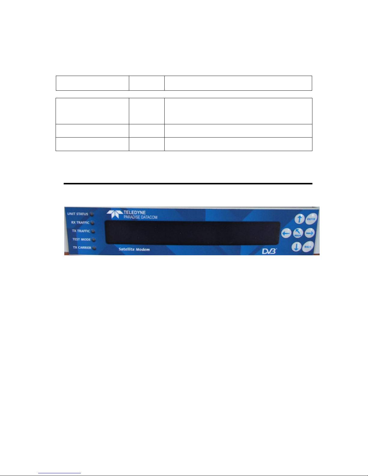
5.5 Optional Front Panel
Figure 5-1 Optional Modem Front Panel
The front panel (shown in Figure 5-1) is an optional item suitable for attaching to
approximately a half-width enclosure and comprises:
• Light Emitting Diodes (LEDs) that provide basic modem status.
• A Liquid Crystal Display (LCD) that acts as the local user interface.
• A keypad for menu navigation and alphanumeric entry.
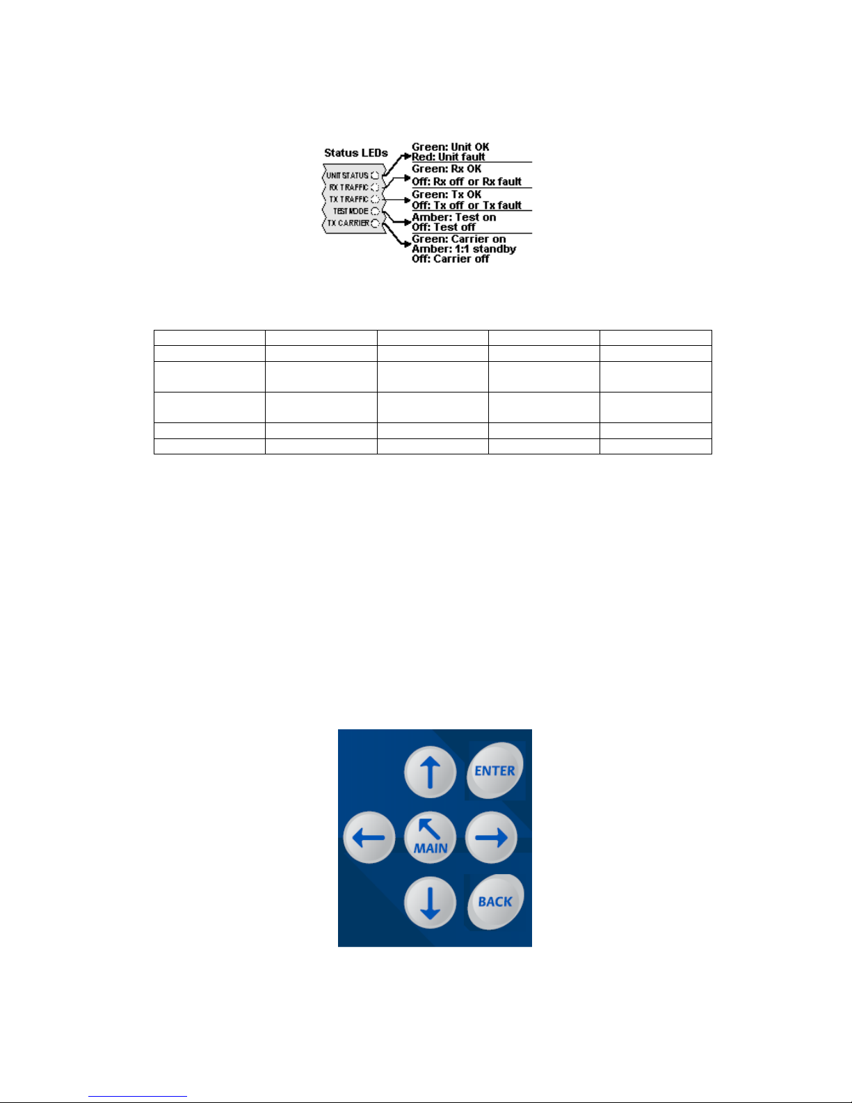
5.5.1 Status Indicators
The five front-panel LEDs display warning and fault information as shown in Figure 5-2
and as described in Table 5-3.
Q-Lite Satellite Modem Installation and Operating Handbook
5-9
Figure 5-2 Front-panel Status Indicators
Off Red Amber
Green
Unit Status
Not used
Unit fault
Not used
Unit OK
Rx Traffic
Rx fault or Rx
disabled
Not used Not used
Rx OK
Tx Traffic
Tx fault or Tx
disabled
Not used Not used
Tx OK
Test Mode
Normal mode
Not used
Test mode
Not used
Tx Carrier
Carrier muted
Not used
1:1 standby Carrier active
Table 5-3 Front-panel LED Status
5.5.2 LCD Display
The backlit LCD is a graphical display formatted to give three lines of 40 text characters
and is highly legible even in strong ambient light. The contrast is adjustable and the
backlight can be switched off or on.
5.5.2.1 Keypad
The keypad (see Figure 5-3) is incorporated into a sealed tactile membrane and allows
full alphanumeric entry and navigation using arrow keys.
Figure 5-3 Front-panel Keypad
Q-Lite Satellite Modem Installation and Operating Handbook
5-10
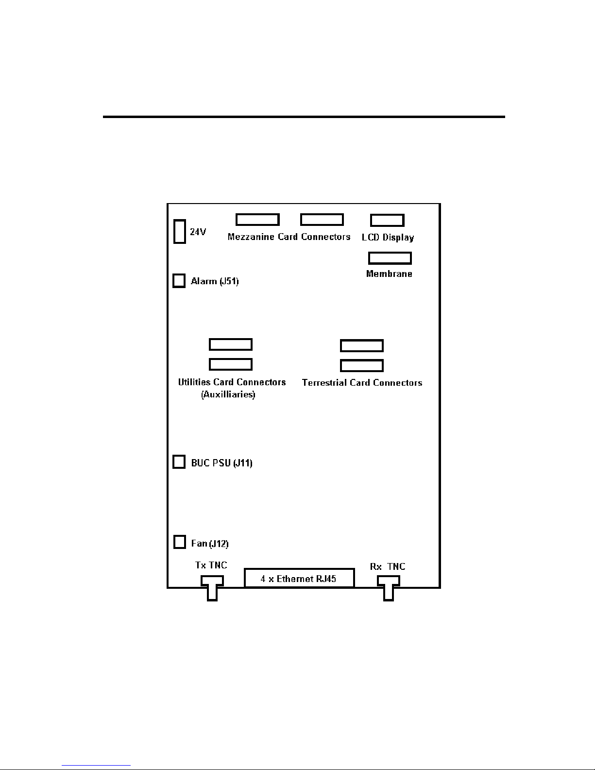
5.6 Q-Lite™ Circuit Board Connectors
The Q-Lite™ circuit board, shown in Figure 6-4, provides a set of terrestrial and satellite
data interfaces. Additional functionality is accessible through the connectors on the Utility
Card. All connector pinouts are defined in Chapter 11.
Figure 5-4 Q-Lite™ Connector Functions

Q-Lite Satellite Modem Installation and Operating Handbook
5-11
The Q-Lite™ circuit board connectors are as follows:
• +24V DC Connector
The modem is designed to operate from a regulated +24V DC input. There is no
further regulation of the 24V provided on the circuit board itself and therefore the
input must be at exactly 24V. A four-way screw-terminal is provided with duplicate
24V and ground pins, allowing for a second independent power source to be used
to increase reliability.
• Alarm Connector (J51)
This is a two-pin Molex single-output summary alarm that combines all of the alarm
states in the modem including traffic and unit alarms. It is an open-collector output
where open circuit indicates that there is an alarm and the closed state (when the
output is pulled to ground) indicates the absence of any fault.
• Tx L-band Output
This is a 50Ω TNC-type femail connector. The output power level can be varied
from 0dBm to –30dBm.
• Terrestrial Interface Position
There is one terrestrial interface position that can be fitted with a variety of interface
cards including EIA-530, G.703, Quad E1, Quad ASI, LVDS, HSSI and STM-1/OC3/Optical Ethernet.
• Rx L-band Input
This is a 50Ω TNC-type female connector. The carrier signal level at the input of the
modem must be in the following range:
Minimum signal level: -130 +10 log (symbol rate) dBm
Maximum signal level: -80 + 10 log (symbol rate) dBm
The maximum wanted-to-composite power level that is supported with no
implementation loss is defined by the equation:
Maximum wanted-to-composite power level: -102 + 10 log (symbol rate) dBm
The maximum composite power level is +10dBm.
 Loading...