

Page 1
Issue 3.0.55, 30 January 2015
2015
EN 55022 - Class B
EN 55024
EN 60950
Teledyne Paradise Datacom Ltd. Teledyne Paradise Datacom LLC
2&3 The Matchyns, Rivenhall End, 328 Innovation Blvd.
Witham, Essex, CM8 3HA, England. State College, PA 16803, U.S.A.
Tel: +44(0)1376 515636 Tel: +1 814 238 3450
Fax: +44(0)1376 533764 Fax: +1 814 238 3829
http://www.paradisedata.com
Copyright © 2013-2015 Teledyne Paradise Datacom Ltd. All rights reserved.
Q-Flex™ Satellite Modem
Installation and Operating Handbook
Page 2

Q-Flex Satellite Modem Installation and Operating Handbook
ii
Table of Contents
Chapter 1 Welcome ................................................................................................ 1-1
Chapter 2 About This Handbook ........................................................................... 2-1
2.1 Conventions ....................................................................................................... 2-1
2.2 Trademarks ........................................................................................................ 2-1
2.3 Disclaimer ........................................................................................................... 2-1
Chapter 3 Safety and Compliance Information .................................................... 3-1
3.1 Safety Compliance ............................................................................................. 3-1
3.2 Environmental Compliance ................................................................................. 3-2
3.3 Electromagnetic Compatibility (EMC) Compliance .............................................. 3-3
Chapter 4 Installation ............................................................................................. 4-1
4.1 Unpacking .......................................................................................................... 4-1
4.2 Line Supply ......................................................................................................... 4-1
4.3 Rack Mounting .................................................................................................... 4-1
4.4 Getting Started ................................................................................................... 4-2
Chapter 5 Introduction ........................................................................................... 5-1
5.1 Overview ............................................................................................................ 5-1
5.2 Standard-Fit Hardware ....................................................................................... 5-2
5.2.1 IF/L-band Operation ........................................................................................ 5-2
5.2.2 Ethernet Operation ......................................................................................... 5-2
5.3 Hardware Options ............................................................................................... 5-3
5.3.1 Terrestrial Interface Option Cards ................................................................... 5-3
5.3.1.1 4-port Gigabit Ethernet Switch ................................................................ 5-3
5.3.1.2 G.703 Option Card .................................................................................. 5-3
5.3.1.3 EIA-530 Option Card ............................................................................... 5-3
5.3.1.4 STM-1/OC-3/Optical Ethernet Option Card ............................................. 5-3
5.3.1.5 IDR Option Card ..................................................................................... 5-4
5.3.1.6 LVDS Option Card .................................................................................. 5-4
5.3.1.7 HSSI Option Card ................................................................................... 5-4
5.3.1.8 Quad E1 Option Card .............................................................................. 5-4
5.3.2 Other Option Cards ......................................................................................... 5-5
5.3.3 BUC Power Supply Options ............................................................................ 5-5
5.4 Software Options ................................................................................................ 5-5
5.5 Front Panel ......................................................................................................... 5-9
5.5.1 Status Indicators ............................................................................................. 5-9
5.5.2 LCD Display .................................................................................................... 5-9
5.5.2.1 Keypad .................................................................................................. 5-10
5.6 Rear Panel ....................................................................................................... 5-10
Chapter 6 User Interfaces ...................................................................................... 6-1
6.1 User Control ....................................................................................................... 6-1
6.1.1 Local Mode ..................................................................................................... 6-1
Page 3

Q-Flex Satellite Modem Installation and Operating Handbook
iii
6.1.2 Takeaway Mode ............................................................................................. 6-1
6.2 Web User Interface ............................................................................................. 6-2
6.2.1 Login Screen .................................................................................................. 6-2
6.2.2 Status Screen ................................................................................................. 6-3
6.2.2.1 Status Setup ........................................................................................... 6-5
6.2.2.2 Status Demodulator ................................................................................ 6-6
6.2.2.3 Status Paired Carrier™ ........................................................................... 6-7
6.2.2.4 Status ACM ............................................................................................. 6-7
6.2.2.5 Status AUPC ........................................................................................... 6-8
6.2.2.6 Status BUC/LNB ..................................................................................... 6-8
6.2.3 Edit Screen ..................................................................................................... 6-8
6.2.4 Edit->Tx-Rx->Service Screen ......................................................................... 6-9
6.2.4.1 Terrestrial Interface ............................................................................... 6-10
6.2.4.2 Rx Values Track Tx ............................................................................... 6-11
6.2.4.3 Tx/Rx Service ........................................................................................ 6-11
6.2.4.4 Tx/Rx Rate Control ................................................................................ 6-12
6.2.4.5 Tx/Rx Data Rate ................................................................................... 6-12
6.2.4.6 Tx/Rx Symbol Rate ............................................................................... 6-13
6.2.4.7 Tx Clock Source .................................................................................... 6-14
6.2.4.8 Rx Clock Source ................................................................................... 6-14
6.2.4.9 Tx/Rx FEC Type ................................................................................... 6-15
6.2.4.10 Tx/Rx Modulation .............................................................................. 6-15
6.2.4.11 Tx/Rx FEC Code Rate ....................................................................... 6-15
6.2.4.12 Tx/Rx Frequency Band ...................................................................... 6-17
6.2.4.13 Tx/Rx Carrier Frequency ................................................................... 6-17
6.2.4.14 Tx/Rx Spectral Roll-off ...................................................................... 6-18
6.2.4.15 Tx/Rx Spectral Inversion ................................................................... 6-19
6.2.4.16 IF/L-band Output Power .................................................................... 6-19
6.2.4.17 Modem/BUC Carrier .......................................................................... 6-20
6.2.5 Edit->Tx-Rx->Service->Advanced Screen .................................................... 6-20
6.2.5.1 DVB-S2 Tx/Rx Pilot Tones .................................................................... 6-20
6.2.5.2 DVB-S2 Tx/Rx Frame Size .................................................................... 6-21
6.2.5.3 Sweep Mode ......................................................................................... 6-21
6.2.5.4 Sweep Width ......................................................................................... 6-21
6.2.5.5 Acknowledge Power Break ................................................................... 6-21
6.2.5.6 Reed-Solomon FEC Options ................................................................. 6-22
6.2.1 Edit->Tx-Rx->Advanced Timeslot Screens ................................................... 6-22
6.2.2 Edit->Tx-Rx->Framing Screen ...................................................................... 6-22
6.2.3 Edit->Tx-Rx->AUPC Screen ......................................................................... 6-22
6.2.3.1 AUPC Mode .......................................................................................... 6-23
6.2.3.2 Target Remote Eb/No ........................................................................... 6-23
6.2.3.3 Maximum AUPC Power Offset .............................................................. 6-23
6.2.3.4 Maximum Negative AUPC Power Offset ............................................... 6-24
6.2.3.5 AUPC Method ....................................................................................... 6-24
6.2.3.6 Carrier Loss Action ................................................................................ 6-24
6.2.3.7 Local Demod Unlocked Action .............................................................. 6-24
6.2.4 Edit->Tx-Rx->BUC/LNB Screen .................................................................... 6-25
6.2.4.1 BUC Interface ....................................................................................... 6-25
6.2.4.2 BUC LO Frequency ............................................................................... 6-26
6.2.4.3 BUC Attenuation ................................................................................... 6-26
6.2.4.4 DC to BUC ............................................................................................ 6-26
6.2.4.5 10MHz to BUC ...................................................................................... 6-26
Page 4

Q-Flex Satellite Modem Installation and Operating Handbook
iv
6.2.4.6 Mute BUC Services in Standby ............................................................. 6-26
6.2.4.7 LNB Type .............................................................................................. 6-27
6.2.4.8 LNB LO Frequency ............................................................................... 6-27
6.2.4.9 DC to LNB ............................................................................................. 6-27
6.2.4.10 10MHz to LNB ................................................................................... 6-27
6.2.4.11 Mute LNB Services in Standby .......................................................... 6-27
6.2.5 Edit->Unit Screen ......................................................................................... 6-27
6.2.6 Edit->Unit->M&C Screen .............................................................................. 6-28
6.2.6.1 Modem Control and Passwords ............................................................ 6-29
6.2.6.2 RADIUS Server IP Address and Fallback Address ................................ 6-29
6.2.6.3 RADIUS Shared Secret ......................................................................... 6-29
6.2.6.4 RADIUS Authentication Validity............................................................. 6-30
6.2.6.5 RADIUS Server Timeout ....................................................................... 6-31
6.2.6.6 Remote M&C Interface .......................................................................... 6-31
6.2.6.7 Modem Identity ..................................................................................... 6-33
6.2.7 Edit->Unit->M&C->SNMP Screen ................................................................. 6-33
6.2.8 Edit->Unit->M&C->Email Screen .................................................................. 6-34
6.2.9 Edit->Unit->M&C->HTTPS Screen ................................................................ 6-37
6.2.10 Edit->Unit->Alarms Screen ....................................................................... 6-38
6.2.10.1 LinkGuard™ Interference .................................................................. 6-38
6.2.10.2 Tx/Rx AIS Alarm Action ..................................................................... 6-38
6.2.10.3 Local/Remote Eb/No Alarm Threshold .............................................. 6-39
6.2.10.4 Buffer Slip Alarm Threshold ............................................................... 6-39
6.2.10.5 BUC DC Current Alarm ..................................................................... 6-39
6.2.10.6 LNB DC Current Alarm ...................................................................... 6-40
6.2.11 Edit->Unit->Station Clock Screen .............................................................. 6-40
6.2.11.1 Station Clock Source ......................................................................... 6-41
6.2.11.2 Station Clock Frequency ................................................................... 6-41
6.2.11.3 Locking the High-Stability Oscillator to the Station Clock ................... 6-42
6.2.12 Edit->Unit->SAF Screen ............................................................................ 6-42
6.2.13 Edit->Unit->Upgrade Screen ..................................................................... 6-43
6.2.14 Edit->Unit->Miscellaneous->Time Screen ................................................. 6-44
6.2.1 Edit->Unit->Miscellaneous->Reset Screen ................................................... 6-44
6.2.1 Edit->Unit->Carrier ID Screen ....................................................................... 6-45
6.2.1.1 Carrier ID Global Unique Identifier ........................................................ 6-46
6.2.1.2 Carrier ID Latitude and Longitude ......................................................... 6-46
6.2.1.3 Carrier ID Custom Message and Telephone Number ............................ 6-46
6.2.1.4 Carrier ID .............................................................................................. 6-46
6.2.2 Edit->IP Screen ............................................................................................ 6-46
6.2.2.1 IP Mode ................................................................................................ 6-47
6.2.2.2 Bridge M&C........................................................................................... 6-49
6.2.2.3 TCP Accleration .................................................................................... 6-49
6.2.2.4 Round-trip Satellite Delay...................................................................... 6-50
6.2.2.5 Header Compression ............................................................................ 6-50
6.2.2.6 Payload Compression ........................................................................... 6-50
6.2.2.7 ACM Mode ............................................................................................ 6-50
6.2.2.8 ACM Rain Fade Margin ......................................................................... 6-52
6.2.2.9 M&C IP Address, Subnet Mask & Modem IP Gateway .......................... 6-52
6.2.2.10 Traffic/Satelite IP Addresses and Subnet Masks ............................... 6-53
6.2.2.11 IP Encapsulation Type ...................................................................... 6-54
6.2.2.12 Encapsulation PID ............................................................................. 6-54
6.2.2.13 MPE MAC Address ........................................................................... 6-55
Page 5

Q-Flex Satellite Modem Installation and Operating Handbook
v
6.2.2.14 Weighted QoS ................................................................................... 6-55
6.2.2.15 IPv4/IPv6 Mode ................................................................................. 6-56
6.2.2.16 M&C and IP Traffic Ethernet Speed/Duplex ...................................... 6-56
6.2.2.17 Ethernet MTU .................................................................................... 6-58
6.2.3 Edit->IP->Advanced Screen.......................................................................... 6-58
6.2.3.1 Terrestrial Buffer Size ........................................................................... 6-59
6.2.3.2 Satellite Buffer Size ............................................................................... 6-60
6.2.3.3 Ethernet Address Learning .................................................................... 6-60
6.2.3.4 Point-to-multipoint Mode ....................................................................... 6-61
6.2.3.5 VLAN Filtering ....................................................................................... 6-61
6.2.3.6 Null Packet Insertion ............................................................................. 6-62
6.2.3.7 PCR Restamping .................................................................................. 6-62
6.2.3.8 MPEG Over IP Type ............................................................................. 6-63
6.2.3.9 Destination Address and Destination Port ............................................. 6-63
6.2.3.10 Local Multicast Address and Local Port ............................................. 6-63
6.2.3.11 Stream Tx/Rx Terrestrial Interface ..................................................... 6-64
6.2.3.12 Stream Tx/Rx Identifier ...................................................................... 6-64
6.2.3.13 Stream Tx Data Rate ......................................................................... 6-64
6.2.3.14 Stream Tx Modulation ....................................................................... 6-64
6.2.3.15 Stream Tx FEC Code Rate ................................................................ 6-65
6.2.3.16 Stream Tx Pilot Tones ....................................................................... 6-65
6.2.3.17 DVB-S2 Tx Frame Size ..................................................................... 6-65
6.2.3.18 Tx/Rx Symbol Rate ........................................................................... 6-65
6.2.4 Edit->IP->QoS Screen .................................................................................. 6-65
6.2.5 Edit->IP->Static Routes Screen .................................................................... 6-66
6.2.6 Edit->IP->Header Compression Routes Screen ............................................ 6-67
6.2.7 Edit->Paired Carrier Screen .......................................................................... 6-68
6.2.7.1 Paired Carrier Enable ............................................................................ 6-68
6.2.7.2 Round-trip Delay ................................................................................... 6-71
6.2.7.3 Satellite Longitude................................................................................. 6-72
6.2.7.4 Earth Station Longitude ......................................................................... 6-72
6.2.7.5 Earth Station Latitude ............................................................................ 6-72
6.2.7.6 Calculated Satellite Delay ..................................................................... 6-73
6.2.7.7 Minimum Round-trip Delay .................................................................... 6-73
6.2.7.8 Maximum Round-trip Delay ................................................................... 6-73
6.2.8 Edit->Memories Screen ................................................................................ 6-73
6.2.8.1 Edit->Memories->Recall Screen ............................................................ 6-74
6.2.8.2 Edit->Memories->Recall->Advanced Reversionary Control Screen....... 6-75
6.2.8.3 Edit->Memories->Store Screen ............................................................. 6-76
6.2.8.4 Edit->Memories->Download Screen ...................................................... 6-77
6.2.8.5 Edit->Memories->Upload Screen .......................................................... 6-77
6.2.9 Edit->Redundancy Screen ............................................................................ 6-78
6.2.10 View Screen .............................................................................................. 6-79
6.2.10.1 Rx Spectrum Monitor ......................................................................... 6-81
6.2.10.2 Rx Constellaton Monitor .................................................................... 6-82
6.2.10.3 IP Graphs .......................................................................................... 6-83
6.2.10.4 Other Time-based Graphs ................................................................. 6-85
6.2.10.5 Alarms ............................................................................................... 6-86
6.2.10.6 System Log ....................................................................................... 6-87
6.2.10.7 View->Setup Screen ......................................................................... 6-87
6.2.10.8 View->Unit Screen ............................................................................ 6-88
6.2.10.9 View->SAF Screen ............................................................................ 6-89
Page 6

Q-Flex Satellite Modem Installation and Operating Handbook
vi
6.2.11 Test Screen .............................................................................................. 6-90
6.2.12 BER Test .................................................................................................. 6-91
6.3 Front-panel Interface ........................................................................................ 6-93
6.3.1 Keypad Operation ......................................................................................... 6-93
6.3.1.1 Cursor ................................................................................................... 6-93
6.3.1.2 Navigation Keys .................................................................................... 6-93
6.3.1.3 Alphanumeric Keys ............................................................................... 6-94
6.3.1.4 Special Function Keys ........................................................................... 6-94
6.3.2 LCD Screen Layout ...................................................................................... 6-95
6.4 Front Panel Menu Structure .............................................................................. 6-96
6.4.1 Main Menu .................................................................................................... 6-96
6.4.2 Status Menu ................................................................................................. 6-97
6.4.3 Edit Menu ..................................................................................................... 6-98
6.4.3.1 Edit->Tx Menu ...................................................................................... 6-99
6.4.3.2 Edit->Rx Menu .................................................................................... 6-100
6.4.3.3 Edit->Unit Menu .................................................................................. 6-101
6.4.4 View Menu .................................................................................................. 6-102
6.4.5 Test Menu ................................................................................................... 6-102
Chapter 7 Modem Concepts .................................................................................. 7-1
7.1 System Clocking ................................................................................................. 7-1
7.1.1 Transmit Clocking ........................................................................................... 7-2
7.1.1.1 Internal Clock .......................................................................................... 7-2
7.1.1.2 Tx Clock In .............................................................................................. 7-2
7.1.1.3 Receive Reference.................................................................................. 7-3
7.1.2 Receive Clocking ............................................................................................ 7-4
7.1.2.1 Satellite ................................................................................................... 7-4
7.1.2.2 Tx Clock In .............................................................................................. 7-4
7.1.2.3 Station Clock ........................................................................................... 7-5
7.1.2.4 Internal Clock .......................................................................................... 7-6
7.1.3 Guidelines for Clocking Configuration ............................................................. 7-6
7.1.3.1 Clock Loop at One End ............................................................................ 7-6
7.1.3.2 No Clock Loop ......................................................................................... 7-7
7.1.3.3 Determining Buffer Size .......................................................................... 7-7
7.1.3.4 G.703 Clock Extension ............................................................................ 7-8
7.2 Automatic Uplink Power Control ......................................................................... 7-8
7.2.1 Introduction ..................................................................................................... 7-8
7.2.2 Configuring AUPC .......................................................................................... 7-9
7.3 1:1 Redundancy Operation ............................................................................... 7-10
7.3.1 Overview....................................................................................................... 7-10
7.3.2 Switching Operation ...................................................................................... 7-10
7.3.3 Setup Procedure ........................................................................................... 7-11
7.3.4 IP Addressing and Operation in Redundancy Configurations ........................ 7-11
7.3.4.1 1:1 IP Operation .................................................................................... 7-11
7.3.4.2 1:N IP Operation ................................................................................... 7-12
7.4 Software Activated Features ............................................................................. 7-12
7.5 Software Upgrading .......................................................................................... 7-13
7.6 LinkGuard™ Interference Detection and Carrier Relocation ............................. 7-14
7.7 FastLink Low-latency LDPC .............................................................................. 7-15
7.8 IP Functionality ................................................................................................. 7-19
7.8.1 Base Modem IP ............................................................................................ 7-19
7.8.2 IP Addressing ............................................................................................... 7-20
Page 7

Q-Flex Satellite Modem Installation and Operating Handbook
vii
7.8.2.1 Gateways .............................................................................................. 7-20
7.8.3 Throughput Performance .............................................................................. 7-20
7.8.4 Jumbo Ethernet Frame Support .................................................................... 7-20
7.8.5 IP Over ESC ................................................................................................. 7-20
7.8.6 IP Interoperability .......................................................................................... 7-22
7.8.7 IP Connectivity Modes .................................................................................. 7-22
7.8.8 TCP Acceleration .......................................................................................... 7-22
7.8.9 Traffic Shaping ............................................................................................. 7-23
7.8.9.1 Guaranteed Bandwidth ......................................................................... 7-23
7.8.9.2 Maximum Bandwidth ............................................................................. 7-23
7.8.9.3 Priority ................................................................................................... 7-24
7.8.9.4 Stream Classification ............................................................................ 7-24
7.8.9.5 Traffic Shaping Graphs ......................................................................... 7-29
7.8.10 Static and Dynamic Routing ...................................................................... 7-30
7.8.11 Header Compression ................................................................................ 7-31
7.8.12 VLAN Operation ........................................................................................ 7-31
7.8.13 Adaptive Coding and Modulation (ACM) ................................................... 7-32
7.9 DVB-S2 and SmartLink ..................................................................................... 7-34
7.10 Paired Carrier™ ................................................................................................ 7-37
Chapter 8 Remote Control Protocol ...................................................................... 8-1
Chapter 9 Data Interfaces ...................................................................................... 9-1
Chapter 10 Connector Pinouts .............................................................................. 10-1
Chapter 11 Fault Messages ................................................................................... 11-1
11.1 Transmit Faults ................................................................................................. 11-2
11.2 Transmit Warnings ........................................................................................... 11-4
11.3 Receive Faults .................................................................................................. 11-5
11.4 Receive Warnings ............................................................................................ 11-7
11.5 Unit Faults ........................................................................................................ 11-9
11.6 Unit Warnings ................................................................................................. 11-10
11.7 Start-up Problems ........................................................................................... 11-10
Chapter 12 Specification Summary ...................................................................... 12-1
12.1 Common Main Specifications ........................................................................... 12-1
12.2 Tx Modulator Specifications .............................................................................. 12-3
12.3 Rx Demodulator Specifications ......................................................................... 12-4
12.4 Clocking and Buffering Specifications ............................................................... 12-4
12.5 Framing and Deframing Specifications ............................................................. 12-5
12.6 Intelsat Reed-Solomon Codec and Custom Option Specifications .................... 12-6
12.7 Drop and Insert Option Specifications ............................................................... 12-6
12.8 Extended Drop and Insert Option Specifications ............................................... 12-7
12.9 Advanced ESC and Advanced Aux Option Specifications ................................ 12-8
12.10 IDR Option Specifications ............................................................................. 12-8
12.11 BERT Option Specifications .......................................................................... 12-9
12.12 AUPC Specifications ................................................................................... 12-10
12.13 Traffic Log Specifications ............................................................................ 12-12
12.14 Common Specifications .............................................................................. 12-12
Page 8

Q-Flex Satellite Modem Installation and Operating Handbook
viii
12.15 Internet Traffic ............................................................................................ 12-13
12.16 BUC / LNB facilities .................................................................................... 12-13
12.17 Performance Graphs .................................................................................. 12-14
Chapter 13 Advanced Framing .............................................................................. 13-1
13.1 Edit->Tx-Rx->Framing Screen .......................................................................... 13-1
13.2 Edit->Tx-Rx>Framing->Overhead Closed Screen ............................................. 13-2
13.3 Edit->Tx-Rx>Framing->Overhead IBS Screen .................................................. 13-4
13.4 Edit->Tx-Rx>Framing->Overhead IDR Screen ................................................. 13-5
13.5 Edit->Tx-Rx>Advanced Drop and Insert Screens ............................................. 13-7
Chapter 14 Glossary .............................................................................................. 14-1
Chapter 15 Technical Support ............................................................................... 15-1
Page 9
Q-Flex Satellite Modem Installation and Operating Handbook
1-1
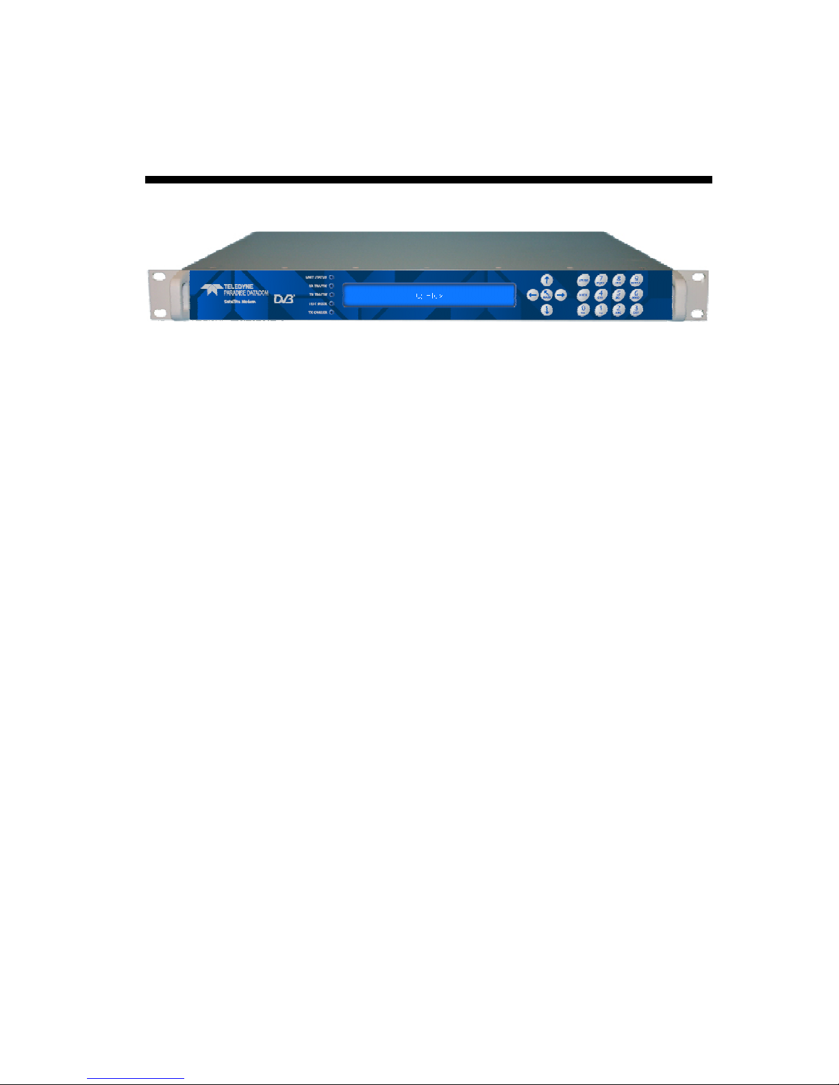
Chapter 1 Welcome
Figure 1-1 Q-Flex™ Advanced Satellite Modem
The Q-Flex™ (Figure 1-1) satellite modem embodies a new concept in satellite modem
technology: a flexible software-defined modem that does what you want, now and in the
future. The Q-Flex™ modem provides a flexible hardware platform with support for IF
(70/140MHz) and L-band operation in one unit. Its powerful processor is ideal for handling
IP traffic. However, the Q-Flex™ modem can be fitted with virtually any type of terrestrial
interface and will operate at data rates up to 160Mbps.
Low cost of ownership is supported by a pay-as-you-go feature set, where individual
features can be enabled when required.
The Q-Flex™ modem incorporates a new software suite called XStream IP™. This has
been created in response to a perceived widespread dissatisfaction in the industry with
the usability and quality of service provided by IP-over-satellite in general. Paradise has
re-engineered every aspect of IP support from the ground up to ensure ease of use, a
high degree of integration between features and outstanding performance and efficiency.
Specifically:
• XStream IP™ is the most advanced integrated suite of IP optimisation and traffic
management features available in any satellite modem.
• XStream IP™ is specifically optimised to be highly efficient and reliable over satellite.
• XStream IP™ provides up to 500,000 packets-per-second processing capability for
lightning-fast IP throughput.
• XStream IP™ is simple to set up and use.
• XStream IP™ includes all IP features as standard making it very good value.
The design aim for the Q-Flex™ was to create the industrys most versatile and
bandwidth-efficient satellite modem. Among the satellite band-width saving features
available are:
• Paired Carrier™, allowing two carriers to be overlapped in the space segment,
saving up to 50% bandwidth.
• DVB-S2 and DVBS2X, state-of-the-art Forward Error Correction (FEC)
representing the most bandwidth-efficient FEC technology available.
• Spectral roll-off factors down to 5%, saving up to 15% bandwidth compared
with 20% roll-off.
• IP compression, saving up to 50% bandwidth.
• Adaptive Coding and Modulation (ACM), saving up to 50% bandwidth.
Page 10

Q-Flex Satellite Modem Installation and Operating Handbook
1-2
• TCP Acceleration, enabling up to 93% bandwidth utilization for TCP traffic.
• ClearLinq™ adaptive Tx pre-distorter, providing up to 2dB compensation for
linear and non-linear distortion in the channel.
• 9-tap Rx equaliser, providing compensation for linear distortion in the channel,
such as from group delay. The equaliser is automatically switched on in all
modes of operation above 10Msps.
New levels of usability are provided by a leading set of built-in diagnostic tools including
spectrum and constellation monitors that facilitate the detection of any link degradation. In
addition, LinkGuard™ is patented technology (US patent 8351495) that monitors
underneath the received carrier for any interference, while on traffic.
The Q-Flex™ modem is backwards compatible with all Quantum and Evolution series
modems.
DVB-S2X, the successor to DVB-S2, is the most efficient and robust coding and
modulation standard available for satellite transmission.
Paradise’s SmartLink™ technology allows non-packetized continuous traffic, such as
G.703 E1 traffic, to be used with DVB-S2. The Q-Flex™ therefore provides a painless
migration path to newer, more efficient communications technology while fully supporting
legacy services.
FastLink™ Low-Density Parity-Check (LDPC) Forward Error Correction (FEC) combines
high coding gain with low latency. FastLink™ can therefore be used to replace both
conventional LDPC (which has high latency) and Turbo Product Code FEC (which has a
lower coding gain).
Paired Carrier™ allows space segment reuse. It overlays transmit and receive carriers in
the same space segment reducing satellite bandwidth requirements by up to 50%. It can
be used at the same time as all our other bandwidth saving techniques. It incorporates
ViaSat’s patented PCMA technology, which is protected under U.S. patent numbers
5,596,439, 6,011,952 and 6,725,017.
This handbook will guide you through the process of installing and using your Q-Flex™
satellite modem (including the Q-FlexE™ and Q-FlexV™ versions).
Redundancy Switch operation is documented separately – see ‘Installation and Operating
Handbook for Quantum, Evolution and Q Series Satellite Redundancy Switches’.
Page 11

Q-Flex Satellite Modem Installation and Operating Handbook
2-1
Chapter 2 About This Handbook
2.1 Conventions
This warning symbol is intended to alert the user to the presence
of a hazard that may cause death or serious injury.
This information symbol is intended to alert the user to the
presence of important operating instructions critical to correct
system function.
2.2 Trademarks
All trademarks used in this handbook are acknowledged to be the property of their
respective owners.
2.3 Disclaimer
Although every effort is made to ensure the accuracy and completeness of the
information in this handbook, this cannot be guaranteed and the information contained
herein does not constitute a product warranty. A separate product warranty statement is
available. Teledyne Paradise Datacom maintains a programme of continuous product
improvement and reserves the right to change specifications without prior notice.
Page 12

Q-Flex Satellite Modem Installation and Operating Handbook
3-1
Chapter 3 Safety and Compliance Information
PLEASE READ THE FOLLOWING INFORMATION BEFORE
INSTALLATION AND USE.
3.1 Safety Compliance
To ensure operator safety, this satellite modem conforms to the provisions of EMC Low
Voltage Directive 2006/95/EC and complies with the following standard:
• EN 60950-1:2006 ‘Safety of Information Technology Equipment, Including
Electrical Business Equipment’.
Prior to installation and at all points during operation the following points must be
observed.
•
This satellite modem must be operated with its cover on at all
times in order to provide protection from potentially lethal internal
voltages. Never operate the unit with the cover removed.
• This satellite modem must be directly connected to a protective
earth ground at all times using the chassis ground stud situated
on the rear of the unit.
• The power system to which this satellite modem is connected
must provide separate ground, neutral and line conductors. The
power system must have a direct ground connection. Note that
the ground stud in itself does not provide a protective earth
connection until the satellite modem is coupled to a suitable
power supply cord containing a protective earth terminal.
• This satellite modem has double pole/neutral fusing. To ensure
operator safety, fuses should always be replaced with identical
type and rating.
• To allow rapid disconnection from the mains in an emergency, the
equipment should be installed near the mains socket outlet,
which should be easily accessible.
Page 13

Q-Flex Satellite Modem Installation and Operating Handbook
3-2
3.2 Environmental Compliance
All Teledyne Paradise Datacom satellite modem products are compliant with the following
EC environmental directives:
• The Reduction of Hazardous Substances (RoHS) Directive 2011/65/EU.
• The Waste Electrical and Electronic Equipment (WEEE) Directive 2012/19/EU.
The equipment is designed to operate in a static 19-inch rack system conforming to IEC
297-2.
The equipment should not be directly connected to the Public Telecommunications
Network.
Operation of the equipment in an environment other than that stated will invalidate the
safety standards.
The equipment must not be operated in an environment in which it
is exposed to:
• Unpressurised altitudes greater than 3000 metres.
• Extreme temperatures outside the stated operating range.
• Excessive dust.
• Moisture or humid atmosphere above 95% relative
humidity.
• Excessive vibration.
• Flammable gases.
• Corrosive or explosive atmosphere.
Page 14

Q-Flex Satellite Modem Installation and Operating Handbook
3-3
3.3 Electromagnetic Compatibility (EMC) Compliance
This satellite modem conforms to the provisions of EMC Directive 2004/108/EC and
complies with the following EC and FCC standards:
• Emissions: EN 55022:2006 Class B – ‘Information Technology Equipment –
Radio Disturbance Characteristics – Limits and Methods of Measurement’.
• Immunity: EN 55024:1998+A1:2001+A2:2003 – ‘Information Technology
Equipment – Immunity Characteristics – Limits and Methods of Measurement ’.
• Federal Communications Commission (FCC) Federal Code of Regulation Part
15, Subpart B.
All D-type connectors must have grounding fingers on the plug shell to guarantee
continuous shielding. The back-shells must comply with the requirements of VDE 0871
and FCC 20708, providing at least 40dB of attenuation from 30MHz to 1GHz. A good
quality cable with a continuous outer shield, correctly grounded, must be used.
Connections to transmit and receive IF interfaces must be made with double-screened
coaxial cable (for example, RG223/U).
The modem Ethernet ports should not be connected directly to outdoor Ethernet cables
that may be be subject to transient overvoltages due to atmospheric discharges and
faults in the power distribution network. Instead, the modem should be connected via an
Ethernet switch or router to provide isolation from overvoltages as recommended in
clause 6 of EN 60950-1.
Page 15

Q-Flex Satellite Modem Installation and Operating Handbook
4-1
Chapter 4 Installation
4.1 Unpacking
Prior to unpacking, inspect the exterior of the shipping container for any sign of damage
during transit. If damage is evident, contact the carrier immediately and submit a damage
report.
Carefully unpack all items, taking care not to discard any packing materials. Should the
unit need to be returned to Teledyne Paradise Datacom then you should use the original
packing carton as it is designed to provide the necessary level of protection during
shipment.
Once unpacked, visually inspect the contents to ensure all parts are present and that
there is no visible damage. Other than the unit itself, the shipping container should
contain a power cord and a Quick Start Guide.
4.2 Line Supply
This satellite modem is classified by the EN 60950-1 safety standard as a ‘pluggable
equipment Class A’. The mains operating range is 90V to 250V. A 48V DC input option is
available. Power consumption ranges from 40W to a maximum of 300W (when a BUC
PSU is fitted).
A power cord suitable for use in the country of operation is provided. If the power cord
needs to be replaced at any point then the replacement must be manufactured to an
equivalent specification. Compatible cable ratings include HAR, BASEC and HOXXX-X.
Compatible connector ratings include BS1636A, BSI, VDE, NF-USE, UL, CSA, OVE,
CEBEC, NEMKO, DEMKO, SETI, IMQ, SEV and KEMA-KEUR.
The installation of the satellite modem and the connection to the line supply must be
made in compliance with local and national wiring regulations for a Category II ‘impulse
over-voltage’ installation. The satellite modem should be positioned to allow a convenient
means of disconnection from the line supply.
4.3 Rack Mounting
If the unit is being installed in a rack then adequate ventilation and cooling should be
provided. There must be adequate clearance around the two side-mounted fans and the
ventilation holes on both sides of the unit.
For rack mounting, there are screw positions on the unit’s front panel for attaching it to the
rack but these must always be used in conjunction with suitable L-brackets underneath the
unit to support its weight.
Page 16

Q-Flex Satellite Modem Installation and Operating Handbook
4-2
4.4 Getting Started
Connect the appropriate cables to the transmit and receive IF and/or L-band connectors at
the rear of the unit, along with the cable(s) for the traffic interface.
Power the unit and wait for it to complete its initialization when it will display summary
status information.
From the front-panel menu, select Main->Edit->All in order to set the configuration prior to
operation.
It is also possible to set up the unit from a web browser as described in Section 7.4.
When setting up a number of units that have similar configurations, the configuration
settings of one unit can be saved, extracted and then transferred to each of the other
units in turn. This procedure is explained in Section 7.4.3.
Getting started is covered in more detail in the Q-Flex™ modem Quick Start Guide
(provided with the unit).
Page 17

Q-Flex Satellite Modem Installation and Operating Handbook
5-1
Chapter 5 Introduction
5.1 Overview
The Q-Flex™ satellite modem is designed for both open and closed network operation in
fixed and mobile environments, providing a data link between geographically distant sites
via satellite.
Features include:
• DVB-S2 (EN 302 307-1) and DVB-S2X (EN 302 307-2) operation including
Adaptive Coding and Modulation (ACM) mode.
• IF frequency ranges of 50 to 90MHz and 100 to 180MHz; L-band frequency range
of 950MHz to 2050MHz (optionally to 2150MHz).
• Open network Intelsat IBS to IESS-309 and IESS-310 and Intelsat IDR to IESS308 and IESS-310, plus Eutelsat SMS to EESS 501. Closed network modes.
• G.703 E1 operation including Drop and Insert (D&I) via T1-D4, T1-ESF and G.732
bearer types.
• Variable data rate between 4.8kbps and 160Mbps.
• BPSK, QPSK, Offset QPSK, 8PSK, 8QAM, 16QAM, 16APSK, 32APSK and
64QAM modulation schemes.
• Forward Error Correction (FEC) options of Turbo Product Code (TPC), FastLink
low-latency Low Density Parity Code (LDPC) and DVB-S2 (as well as legacy
FECs).
• Spectral roll-off factors of 5%, 10%, 15%, 20%, 25% and 35%.
• A full range of terrestrial interfaces including Internet Protocol (IP), RS422, V.35,
RS232, LVDS, HSSI, STM-1, OC-3, Optical Ethernet and G.703 (T1/E1, T2/E2
and T3/E3). The Quad E1 interface card multiplexes four E1 interfaces together
onto a single carrier and also serial data, G.703 and IP traffic to be multiplexed
together onto a single carrier.
• Automatic Uplink Power Control (AUPC) automatically adjusts modem output
power to maintain a constant Eb/No at the distant end of the satellite link.
• Front panel display and keypad for local control.
• Remote equipment can be controlled over the satellite via serial or IP traffic
interfaces. Remote modem control is supported via web browsing, the Simple
Network Management Protocol (SNMP), Telnet and the proprietary Paradise
Universal Protocol (PUP) command protocol. As well as supporting the
development of third-party user interfaces for modem control, the PUP protocol
includes many useful hooks for satellite listening applications (such as the output
of I and Q baseband samples).
• Compact 1U chassis, 405mm deep.
• XStream IP™, providing an advanced integrated suite of IP optimisation and
traffic management features. These include Transport Control Protocol (TCP)
acceleration, header and payload compression, encryption, static and dynamic
routing, Dynamic Host Control Protocol (DHCP), IEEE 802.1p Quality of Service
(QoS) support, IEEE 802.1q VLAN support, traffic shaping and Adaptive Coding
and Modulation (ACM). A dual IPv4/IPv6 TCP/IP stack is provided. IPv4 support is
provided for all IP functions as the default. With respect to IPv6, bridging and
routing are supported along with an IPv6 embedded web server. Modem IP
Page 18

Q-Flex Satellite Modem Installation and Operating Handbook
5-2
addresses and static routes can also be entered and displayed in IPv6 format.
TCP acceleration is supported at up to the maximum data rate for the modem.
Up to 10000 concurrent accelerated TCP connections are supported along with up
to 40,000 unaccelerated TCP connections. Bandwidth utilization when TCP
acceleration is enabled is typically over 90%. Bridging, static routing and
dynamic routing (RIP V1 and V2, OSPF V2 and V3 and BGP V4) are all
supported. Ethernet, IP, User Datagram Protocol (UDP) and Real Time Protocol
(RTP) header compression are supported. The 14-byte Ethernet frame is
typically compressed to one byte. IP/UDP/RTP headers are typically compressed
to between one and three bytes. The one-way packet processing limit for header
compression is 60,000 packets per second (pps); the two-way limit is 45,000 pps.
IP/UDP/RTP header compression is compliant with the RFC 3095 (Robust Header
Compression) standard. IP payload compression is provided (compliant with the
RFC 1951 ‘DEFLATE’ standard). This compresses TCP and UDP packet
payloads by typically 50%.
5.2 Standard-Fit Hardware
5.2.1 IF/L-band Operation
The following are provided as standard:
• IF operation, via transmit and receive IF BNC connectors (supporting 50Ω and
75Ω operation at 50 to 90MHz and 100 to 180MHz).
• L-band operation, via transmit and receive L-band N-type connectors (supporting
50Ω operation at 950 to 2150MHz).
• A high-stability L-band 10MHz reference signal for output to a Block Up Converter
(BUC) or Low-Noise Block (LNB) in order to phase-lock the BUC or LNB’s local
oscillator to a highly stable frequency reference. The 10MHz reference can also
be output through the 50Ω BNC station clock connector.
• A Frequency Shift Keying (FSK) capability for performing FSK communications to
and from a compatible BUC or IF transceiver. This allows remote monitoring and
control of the BUC or transceiver via a modulated FSK signal on the Inter-Facility
Link (IFL) cable.
5.2.2 Ethernet Operation
Two Gigabit Ethernet RJ45 connectors are fitted as standard. One of these is used for
modem Monitor and Control (M&C) and the other is for satellite traffic. These provide a
combined 150,000 packets-per-second processing capability. Layer 2 bridging and Layer
3 routing are supported in software.
Trunking mode is our name for a hardware Layer 2 bridge that supports 160Mbps bidirectional traffic at up to 500,000 packets per second with zero jitter. Trunking mode
supports ACM (and AUPC) but for all other XStream IP™ features, such as compression,
a non-trunking mode must be selected.
Page 19

Q-Flex Satellite Modem Installation and Operating Handbook
5-3
A 4-port Gigabit Ethernet switch option is available. This extends the base modem
Ethernet traffic port with another 3 Ethernet ports, creating a 4-port switch.
Ethernet speed, duplex and cable termination (crossover versus straight-through) are
auto-negotiated. Speed and duplex can be set to fixed values if desired.
5.3 Hardware Options
5.3.1 Terrestrial Interface Option Cards
One interface position is available for fitting a terrestrial interface card. Any of the
following option cards may be fitted in these interface positions (note that fitting duplicate
cards of the same type is not supported).
5.3.1.1 4-port Gigabit Ethernet Switch
The 4-port Gigabit Ethernet switch card (part number P3718) extends the base modem
Ethernet traffic port with three further RJ45 Ethernet ports, creating a 4-port switch.
5.3.1.2 G.703 Option Card
The G.703 option card (part number P3722) provides support for G.703 E1/T1, E2/T2 and
E3/T3 traffic rates. Unbalanced G.703 is provided on two BNC 75Ω sockets and balanced
G.703 is provided on two RJ45 sockets. The following software features are included as
standard with the G.703 option card:
• G.703 clock extension, providing a high-stability reference clock over satellite
(alternative to GPS). In this mode the G.703 card is used purely as a high-stability
clock generator for some other traffic source, such as serial data.
• Timeslot Drop & Insert feature, allowing fractional E1/T1 services.
5.3.1.3 EIA-530 Option Card
The EIA-530 option card (part number P3720) provides selectable RS422, X.21, V.35 and
RS232 operation up to 10Mbps via a 25-way D-type female connector.
5.3.1.4 STM-1/OC-3/Optical Ethernet Option Card
The STM-1/OC-3/Optical Ethernet option card (part number P3723) provides selectable
STM-1, OC-3 and optical Ethernet operation up to 160Mbps. An open-standard SFP cage
is fitted that can be used with a wide range of SFP modules. All optical connector types
(such as LC and SC) and all types of optical cable (single-mode, multi-mode, all
wavelengths) are supported, subject to a compatible SFP module being fitted. Due to the
wide range of optical cabling and connector options, no SFP module is provided with the
card.
Page 20

Q-Flex Satellite Modem Installation and Operating Handbook
5-4
5.3.1.5 IDR Option Card
The Intermediate Data Rate (IDR) option card (part number P3721) provides an IESS
308-compliant IDR capability including two 32kbps ADPCM ESC audio channels, multiple
backward alarms support and independent ESC and Auxiliary ports that replace the
shared ESC/Aux port on the base unit. The connectivity is via a 50-way D-type female
connector.
The following software features are included as standard with the IDR option card:
• Advanced AUX feature providing variable rate synchronous Aux channel. This
includes the option to replace IDR audio channels with serial data.
• Audio option. For IBS carriers this allows two audio streams in 64kbps or two
audio and 64kbps data in 128kbps (this requires the IBS option).
5.3.1.6 LVDS Option Card
The Low Voltage Differential Signal (LVDS) option card (part number P3001) provides
LVDS at data rates of up to 60Mbps via a 25-way D-type female connector.
5.3.1.7 HSSI Option Card
The High Speed Serial Interface (HSSI) option card (part number P3705) provides HSSI
at data rates of up to 60Mbps via an industry-standard 50-way SCSI-2 DCE connector.
5.3.1.8 Quad E1 Option Card
The Quad E1 option card (part number P3706) supports four synchronous G.703 HDB3encoded balanced RJ45 ports. Along with full E1 bearers, Drop and Insert of up to 32
timeslots is provided on all four interfaces. The Quad E1 card and G.703 card are
compatible when used for a single full E1.
All data rates between 64kbps and 8448kbps are supported in multiples of 64kbps. The
data is multiplexed onto a single carrier using either an IBS frame format (with overhead
of 6.7%) or Closed Network frame format (with no overhead) or Closed Network + ESC
frame format (with overhead of less than 0.5%). The absolute minimum amount of
bandwidth is used in all cases, in direct proportion to the required number of timeslots.
The Quad E1 card MultiMux feature allows E1, serial and IP traffic to be multiplexed
together onto a single carrier. Multimux operation is explained in the document ‘Multimux
Data Multiplexer Option’ (Application Note No. 205348) from the modem documentation
area of http://www.paradisedata.com. It allows many different combinations of interfaces
to be combined onto a single carrier including:
• Up to two E1s plus up to 2Mbps of IP and up to 2Mbps of EIA-530 data (or up to
three E1s when using either IP or EIA-530 but not both).
• Up to two E1s plus up to 4Mbps of IP.
Page 21

Q-Flex Satellite Modem Installation and Operating Handbook
5-5
• E1 with two separate EIA-530 interfaces.
• IP at up to 30Mbps with EIA-530.
• IP with G.703 at E3 rate.
5.3.2 Other Option Cards
The following feature-specific option cards are available:
• P3604 DVB-S2 option card, required for DVB-S2 and SmartLink™ operation.
• P3609 DVB-S2X option card, required for DVB-S2X operation. This can also be
used for DVB-S2 to gain superior performance (e.g. higher supported symbol rate)
when compared to the P3604 card.
• P3605 FastLink™ option card, required for FastLink™ low-latency Low-Density
Parity-Check (LDPC) Forward Error Correction (FEC) operation.
• P3607 Paired Carrier™ option card, required for Paired Carrier™ operation
(which overlays transmit and receive carriers in the same space segment reducing
the overall required satellite bandwidth).
5.3.3 BUC Power Supply Options
The satellite modem may optionally be fitted with a Power Supply Unit (PSU) for powering
a Block Up Converter (BUC) when operated in L-band mode. Refer to Table 5-1 for the
available BUC power supply options.
Part Number BUC PSU
Type
P3543 200W 24V output
A.C. in/D.C. out
P3544 200W 48V output
A.C. in/D.C. out
P3545 +/-48V input, 200W 24V output
D.C. in/D.C. out
P3546 +/-48V input, 200W 48V output
D.C. in/D.C. out
P3547 +48V input, 200W 48V output
D.C. in/D.C. out
Table 5-1 BUC Power Supply Options
5.4 Software Options
Several software options, known as Software Activated Features (SAF), are available as
shown in Table 5-2. These can be purchased on a pay-as-you-go basis and
retrospectively activated in deployed units as required. The SAF concept (including timelimited free access to most features) is explained in Section 8.5.
In the table, the SAF Code column lists the acronyms by which features are referred to on
the modem’s local user interface.
Page 22

Q-Flex Satellite Modem Installation and Operating Handbook
5-6
Feature
SAF
Code
Description
Transmit
TX Enables the Tx service.
Receive
RX Enables the Rx service.
Terrestrial data rate
0 to 2048kbps
DR0 Enables data rates in the given range.
Terrestrial data rate
0 to 5Mbps
D1L Enables data rates in the given range.
Terrestrial data rate
0 to 10Mbps
D1H Enables data rates in the given range.
Terrestrial data rate
0 to 25Mbps
DR2 Enables data rates in the given range.
Terrestrial data rate
0 to 60Mbps
DR3 Enables data rates in the given range.
Terrestrial data rate
0 to 100Mbps
DR4 Enables data rates in the given range.
Terrestrial data rate
0 to 160Mbps
DR5 Enables data rates in the given range.
XStream IP
™
XSIP This provides the following features:
• IP traffic shaping. Provides guaranteed
throughput levels for specific IP streams using
Committed Information Rate and Burst Information
Rate. Stream differentiation is by IP address, IEEE
802.1p priority class, Diffserv DSCP class, MPLS
EXP field, VLAN ID or PID value.
• IP header compression. Enables Ethernet, TCP,
UDP, IP and RTP packet header compression.
• IP payload compression. Enables TCP and UDP
payload compression compliant to RFC 1951
(‘DEFLATE’).
• Dynamic routing. Enables choice of RIP V1 and
V2, OSPF V2 and V3 and BGP V4 dynamic
routing.
• TCP acceleration. Acceleration of TCP data over
satellite to the prevailing data rate of the modem.
• AAA RADIUS secure user login. Authentication,
Authorisation & Accounting. Gives greater access
control and accountability by replacing standard
modem login with user’s personal company
network login credentials.
• Encryption. AES 256-bit key encryption of IP
packets. Note that encryption is export-controlled
technology and is provided on the Q-FlexE model
only.
Table 5-2 Software Activated Features (continues over page)
Page 23

Q-Flex Satellite Modem Installation and Operating Handbook
5-7
Feature
SAF
Code
Description
XStream IP
™
DVB-S2
• IP-over-DVB encapsulation. Supports the
transmission of IP packets with/without Ethernet
frames over DVB-S2/DVB-S2X using Multiprotocol
Encapsulation (MPE) (EN 301 192), Unidirectional
Lightweight Encapsulation (ULE) (RFC 4326) and
Paradise XStream Encapsulation (PXE).
• ACM. Enables DVB-S2/DVB-S2X Adaptive Coding
and Modulation (ACM).
• VCM. Allows either two ASI streams, or one ASI
stream and one IP stream, to be multiplexed onto a
single carrier.
DVB-S2
X CCM
Tx
S2XT Enables DVB-S2X Tx operation for all supported
modulations. Includes XStream IP™ DVB-S2.
DVB-S2X
CCM
Rx
S2XR Enables DVB-S2X Rx operation for all supported
modulations. Includes XStream IP™ DVB-S2.
DVB-S2 Tx
DVB2T Enables DVB-S2 Tx operation for all supported
modulations. Includes SmartLink™ and XStream IP™
DVB-S2.
DVB-S2 Rx
DVB2R Enables DVB-S2 Rx operation for all supported
modulations. Includes SmartLink™ and XStream IP™
DVB-S2.
DVB-
S2X Low
-
latency
Mode
S2XLL Enables the following proprietary extensions to DVB-
S2X:
• Very Short Frame: Frame size of 5,400 bits,
reducing latency to 33% of standard DVB-S2 Short
frame; supports QPSK/8PSK/16APSK/32APSK
2/5, 7/15, 8/15, 3/5, 2/3, 11/15, 4/5, 13/15, 14/15
• Ultra Short Frame: Frame size of 3,240 bits,
reducing latency to 20% of standard DVB-S2 Short
frame; supports QPSK/8PSK/16APSK/32APSK
1/3, 4/9, 5/9, 2/3, 7/9, 8/9
ClearLinQ™
Adaptive
Tx Predistorter
CLNQ Corrects for linear and non-linear distortion in the RF
chain. Applicable to all FECs and modulations
including DVB-S2X, FastLink™ and TPC.
FastLink
™ LDPC
FL
Enables
FastLink
™
low-latency LDPC to the
prevailing data rate of the modem (subject to maximum
data rate of 100Mbps). Includes all relevant
modulations and FEC rates.
Paired Carrier
™
56kbps to 256kbps
PCMZ
Enables
Paired Carrier
™
data rates in the given range
(inclusive). Incorporates ViaSat’s patented PCMA
technology. For all supported data rates, Paired
Carrier™ is subject to a minimum occupied bandwidth
of 30kHz and a maximum of 54MHz.
Paired Carrier
™
256kbps to 512kbps
PCMA
Enables
Paired Carrier
™
data rates in the given
range.
Paired Carrier
™
512kbps to 1.024Mbps
PCMB
Enables
Paired Carrier
™
data rates in the given
range.
Paired Carrier
™
1.024Mbps to 2.5Mbps
PCMC
Enables
Paired Carrier
™
data rates in the given
range.
Table 5-2 Software Activated Features (continues over page)
Page 24

Q-Flex Satellite Modem Installation and Operating Handbook
5-8
Feature
SAF
Code
Description
Paired Carrier
™
2.5Mbps to 5Mbps
PCMD Enables Paired Carrier™ data rates in the given range.
Paired Carrier
™
5Mbps to 10Mbps
PCME Enables Paired Carrier™ data rates in the given range.
Paired Carrier
™
10Mbps to 15Mbps
PCMF Enables Paired Carrier™ data rates in the given range.
Paired Carrier
™
15Mbps to 20Mbps
PCMG Enables Paired Carrier™ data rates in the given range.
Paired Carrier
™
20Mbps to 25Mbps
PCMH Enables Paired Carrier™ data rates in the given range.
Paired Carrier
™
25Mbps to 30Mbps
PCMI Enables Paired Carrier™ data rates in the given range.
Paired Carrier
™
30Mbps to 40Mbps
PCMJ Enables Paired Carrier™ data rates in the given range.
Paired Carrier
™
40Mbps to 50Mbps
PCMK Enables Paired Carrier™ data rates in the given range.
Paired Carrier
™
50Mbps to 60Mbps
PCML Enables Paired Carrier™ data rates in the given range.
Paired Carrier
™
60Mbps to 80Mbps
PCMM Enables Paired Carrier™ data rates in the given range.
Paired Carrier
™
80Mbps to 100Mbps
PCMN Enables Paired Carrier™ data rates in the given range.
Paired Carrier
™
100Mbps to 160Mbps
PCMO Enables Paired Carrier™ data rates in the given range.
Optimised spectral roll
-
off
ROFF Enables 5%, 10% and 15% spectral roll-off options.
Wideband
WRF Extends L-band operation upper frequency limit from
2050MHz to 2150MHz.
DVB-CID
CID
DVB Carrier ID
.
Tx carrier identification per ETSI 103
129.
Packet
Synchronisation
PTP Supports IEEE 1588 Precision Time Protocol Version
2.
IBS
IBS Enables IBS service (to IESS 309) with low-rate
Intelsat ESC (to IESS 403) and high-rate IBS ESC.
Legacy FECs
IRS
SEQ
TCM
TPL
TPH
Enables
Sequential
FEC (limited to 2.048Mbps);
TCM
8PSK 2/3 to IESS 310; Viterbi BPSK/QPSK/OQPSK
FEC rates 1/2, 3/4 & 7/8; Intelsat Reed-Solomon outer
codec
LinkGuard
™
LG
LinkGuard
™
signal-under-carrier interference
detection.
Table 5-2 Software Activated Features
Page 25
Q-Flex Satellite Modem Installation and Operating Handbook
5-9
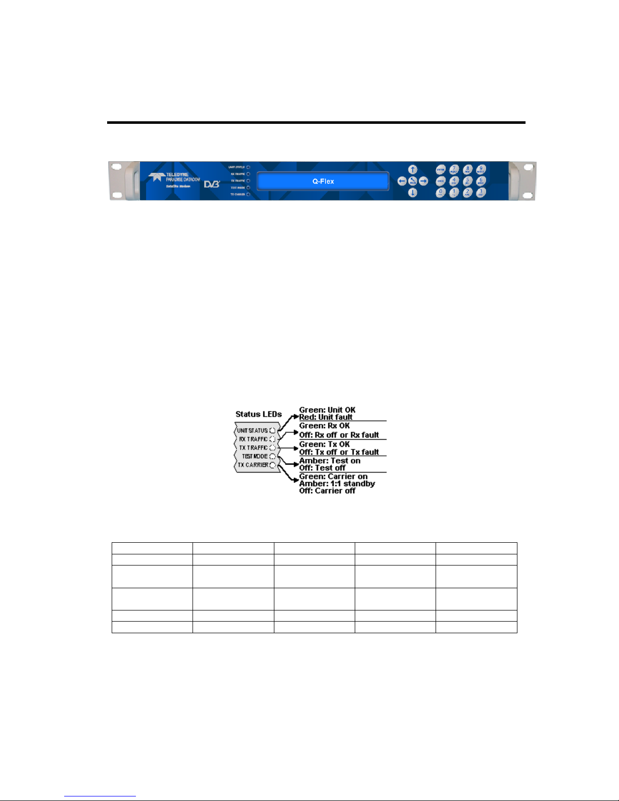
5.5 Front Panel
Figure 5-1 Modem Front Panel
The front panel, shown in Figure 5-1, comprises:
• Light Emitting Diodes (LEDs) that provide basic modem status.
• A Liquid Crystal Display (LCD) that acts as the local user interface.
• A keypad for menu navigation and alphanumeric entry.
5.5.1 Status Indicators
The five front-panel LEDs display warning and fault information as shown in Figure 5-2
and as described in Table 5-3.
Figure 5-2 Front-panel Status Indicators
Off Red Amber
Green
Unit Status
Not used
Unit fault
Not used
Unit OK
Rx Traffic
Rx fault or Rx
disabled
Not used Not used
Rx OK
Tx Traffic
Tx fault or Tx
disabled
Not used Not used
Tx OK
Test Mode
Normal mode
Not used
Test mode
Not used
Tx Carrier
Carrier muted
Not used
1:1 standby Carrier active
Table 5-3 Front-panel LED Status
5.5.2 LCD Display
The backlit LCD is a graphical display formatted to give three lines of 40 text characters
and is highly legible even in strong ambient light. The contrast is adjustable and the
backlight can be dimmed or brightened as required.
Page 26
Q-Flex Satellite Modem Installation and Operating Handbook
5-10
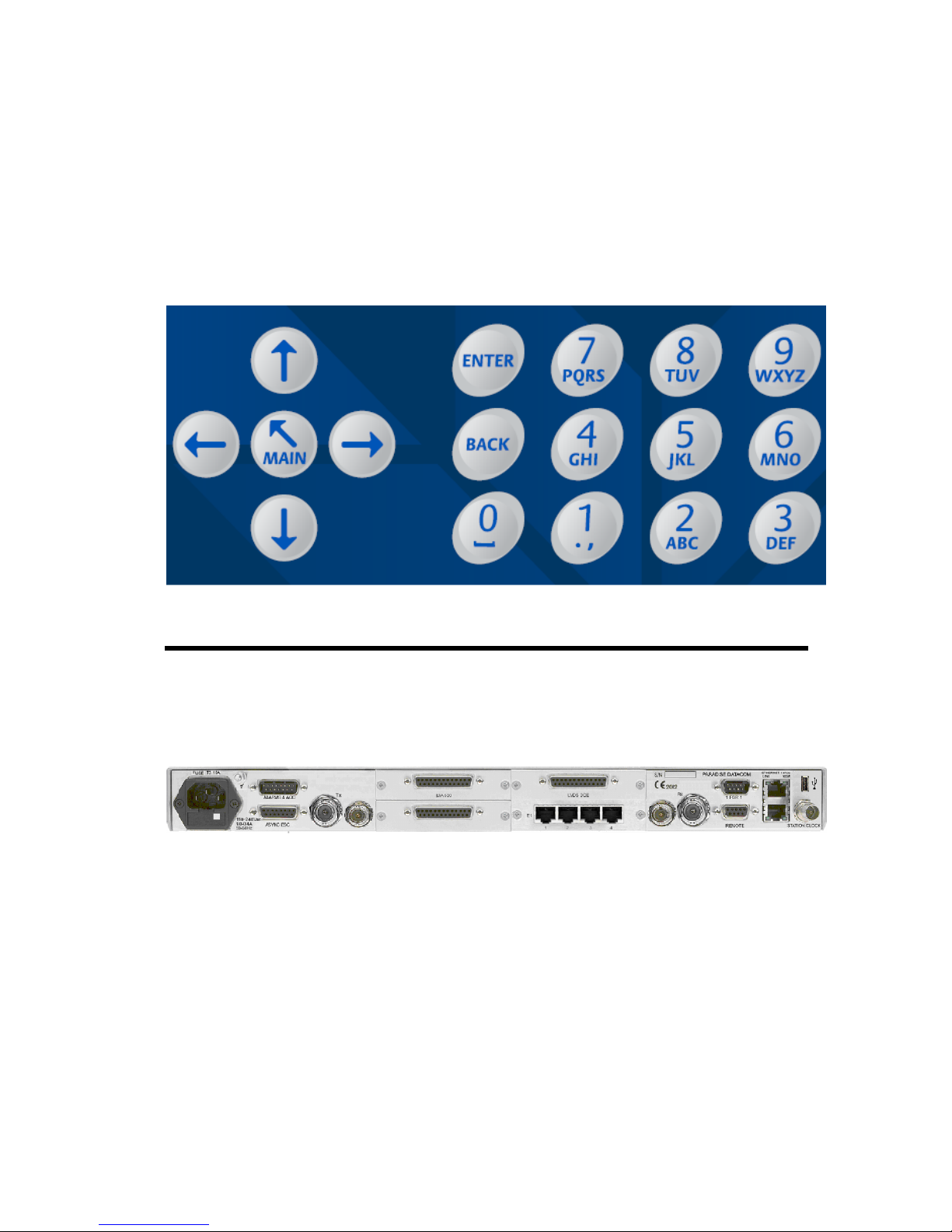
5.5.2.1 Keypad
The keypad (see Figure 5-3) is incorporated into a sealed tactile membrane and allows
full alphanumeric entry and navigation using arrow keys.
Figure 5-3 Front-panel Keypad
5.6 Rear Panel
The rear panel, shown in Figure 6-4, provides a full set of terrestrial and satellite data
interfaces. Connector pinouts are defined in Chapter 11.
Figure 5-4 Modem Rear Panel
From left to right, the rear panel consists of:
• IEC Mains Power Connector/Voltage Selector/Fuse
The modem is designed to operate from a mains AC supply of 100 to 240V (90 to
250VAC, 1A @100V, 0.5A @ 240V, 47 to 63Hz). The IEC connector incorporates
two fuses, independently fusing both live and neutral lines. Access to the fuses is
provided by a slide-out tray. Both fuses are standard 20mm type, rated T3.15A, of
the slow-blow (time-delay) type.
• Chassis Ground Stud
Page 27

Q-Flex Satellite Modem Installation and Operating Handbook
5-11
There is an M4 stud for connecting a safety earth conductor directly to the chassis
of the unit.
• Tx IF Output
This is a 50Ω/75Ω BNC female connector. The output power level can be varied
from 0dBm to -25dBm.
• Tx L-band Output
This is a 50Ω N-type female connector. The output power level can be varied from
0dBm to –30dBm.
• Alarms and AGC Connector
This is a 15-pin D-type male connector that provides access to four ‘form-C’ relay
contacts that indicate alarm conditions. An AGC output is provided that is suitable
for peaking antenna position.
The alarm relays have the following definitions:
Unit Fault: A fault exists on the unit indicating an equipment failure.
Traffic Prompt: A Tx traffic fault exists.
Rx Traffic Prompt: An Rx traffic fault exists.
Deferred Alarm: One of the following conditions exists:
• The receive Eb/No is lower than the user-defined threshold.
• Buffer slips are more frequent than the user-defined threshold.
• A backward alarm is being received from either the satellite or terrestrial
ports.
• Async ESC Connector
This is a 15-pin D-type female connector. It provides an RS232/RS422/RS485
asynchronous port for either a high-rate Async Engineering Service Channel (ESC)
facility (for IBS or Closed Network plus ESC services) or the IBS ‘low-rate Intelsat
oversampled ESC facility’ (which is configured as the Aux channel on the modem).
When the IDR option is fitted, separate ports for the ESC and Aux channels on the
IDR card replace the ESC and Aux functions on the Async ESC connector, which
are disabled. The Async ESC connector also provides an RS422-compatible Station
Clock input.
Page 28

Q-Flex Satellite Modem Installation and Operating Handbook
5-12
• On-line LED
This LED mirrors the front-panel Tx Carrier LED allowing the operator, from the rear
of the modem, to ascertain the carrier status and to identify which modem in a 1:1
redundant pair is offline.
• Optional Terrestrial Interface Positions
There are four terrestrial interface positions that can be fitted with a variety of
interface cards including EIA-530, G.703, Quad E1, Quad ASI, LVDS, HSSI and
STM-1/OC-3/Optical Ethernet.
The G.703 interface card supports T1, E1, T2, E2, T3 and E3 data rates. Balanced
operation is provided on two RJ45 connectors while unbalanced operation is via two
BNC connectors. For balanced operation, T1 line impedance is 100Ω, E1 line
impedance is 120Ω and T2 line impedance is 110Ω. Unbalanced E1, T2, E3 and T3
line impedance is 75Ω. Line impedance is software selectable.
• ESC and Aux Connector (IDR Option Card)
When fitted, the IDR option card provides access to:
• Four backward-alarm ‘form-C’ relay outputs and four backward-alarm inputs,
together with an Rx summary-alarm signal.
• Two audio ESC ports (with 4-wire 600Ω impedance and input range +7dBm to -
16dBm) for use in IDR operation. These ports may also be used in IBS services
to generate a 64kbps IBS carrier comprised of two 32kbps ADPCM audio
channels or a 128kbps IBS carrier comprised of 64kbps data (from the main
data interface of the modem) plus two 32kbps ADPCM audio channels.
• An RS232/RS422/RS485 port for synchronous and asynchronous ESC traffic.
This port replaces the shared ESC/Aux function on the rear-panel Async ESC
connector. It provides an 8kbps synchronous IDR ESC channel. If the Async
ESC feature is available then this port provides an asynchronous 8kbps channel
and a high-rate asynchronous ESC in IBS and Closed Network + ESC services.
• An RS232/RS422 port for synchronous and asynchronous Aux traffic. This port
replaces the shared ESC/Aux function on the rear-panel Async ESC connector.
The port provides a 32kbps or 64kbps IDR overhead channel in place of one or
both of the IDR 32kbps ADPCM audio ESC channels. In IBS, this port may be
configured to provide either the IBS ‘low-rate Intelsat oversampled ESC facility’
or a higher-rate synchronous channel within the IBS overhead.
• Rx IF Input
This is a 50Ω/75Ω BNC female connector. The carrier signal level at the input of the
modem must be in the following range:
Minimum signal level: -115 +10 log (symbol rate) dBm
Maximum signal level: -80 + 10 log (symbol rate) dBm
Page 29

Q-Flex Satellite Modem Installation and Operating Handbook
5-13
The maximum wanted-to-composite power level that is supported with no
implementation loss is defined by the equation:
Maximum wanted-to-composite power level: -94 + 10 log (symbol rate) dBm
The maximum composite power level is +10dBm.
• Rx L-band Input
This is a 50Ω N-type female connector. The carrier signal level at the input of the
modem must be in the following range:
Minimum signal level: -130 +10 log (symbol rate) dBm
Maximum signal level: -80 + 10 log (symbol rate) dBm
The maximum wanted-to-composite power level that is supported with no
implementation loss is defined by the equation:
Maximum wanted-to-composite power level: -102 + 10 log (symbol rate) dBm
The maximum composite power level is +10dBm.
• Fans
There are two side-mounted high-performance fans that draw air in through
ventilation holes in the sides of the unit and expel the air outwards. The side vents
must not be blocked.
• 1:1 Redundancy Connector
The modem has a built-in 1:1 redundancy controller that connects to the other
modem in the 1:1 pair via a 9-pin D-type male connector. A 1:1 redundancy system
requires two modems, a 1:1 control cable between the two redundancy connectors,
a ‘Y’ cable for splitting the traffic path and passive splitters and combiners for the IF
ports. An overview of 1:1 operation is provided in Section 8.4.
• Remote M&C Connector
This is a 9-pin D-type female connector. The modem supports the Paradise
Universal Protocol (PUP) as specified in the document ‘Remote M&C Specification
for Q-Flex™ Satellite Modem’. RS232 (for direct-to-PC applications) and RS485
(for multidrop applications) are supported. The Remote M&C interface can be
connected to the remote modem’s Async ESC interface, allowing remote modem
control over satellite.
• Ethernet IP Traffic and Remote M&C Connectors
Two Gigabit Ethernet RJ45 connectors are provided for modem Monitor and
Control (M&C) and satellite traffic respectively. Ethernet speed, duplex and cable
Page 30

Q-Flex Satellite Modem Installation and Operating Handbook
5-14
termination (crossover versus straight-through) are auto-negotiated. Line speed
and duplex can also be set to fixed values. The two Ethernet ports can be bridged
together under software control.
M&C control can be via the Simple Network Management Protocol (SNMP), an
embedded web server that sends web pages to a web browser, a Telnet-style
terminal emulation application or via TCP packets that encapsulate Paradise
Universal Protocol (PUP) commands.
SNMP is disabled by default and must be enabled before it can be
used. Once enabled, the modem will always respond to SNMP
commands regardless of whether it has been placed in a mode
that restricts user control to the front panel only.
When using the M&C interface, an M&C IP address (including subnet mask and
default gateway) must be set. An IP traffic address is not required when operating in
Ethernet bridging modes. IP addresses are described in Section 7.8.2.
• Station Clock
This is a 75Ω BNC female connector that accepts a 1MHz to 10MHz signal, either
a square wave of >1V peak-to-peak or a sine wave at a power level of 0dBm or
greater. Alternatively, the station clock signal can be input as an RS422 signal on
the Async ESC connector.
The station clock acts as a clock for either the modem receive circuit (or, if the
input is at exactly 10MHz, for both the receive and transmit circuits). It is therefore
possible to maintain clock synchronization between several modems by feeding a
common master clock signal into all of them.
Page 31

Q-Flex Satellite Modem Installation and Operating Handbook
6-1
Chapter 6 User Interfaces
6.1 User Control
The modem has both front-panel and web browser user interfaces.
For remote web browsing, there are two fixed user names, namely, admin and user. The
admin user can view and change the modem configuration, while user can only view the
modem settings. Only admin can change the passwords associated with these two user
names.
There is no restriction on the number of users (as either admin or user) that can be
logged in at the same time. Remote admin users who log in while the modem is under
local front-panel control will be restricted to view-only permissions.
6.1.1 Local Mode
Local mode allows control of the modem from the front-panel interface only. Web users
are still able to log in and view the modem settings in this mode.
6.1.2 Takeaway Mode
In Takeaway mode, the modem can be controlled through the front-panel or via a remote
admin user at the same time. When the modem is switched out of Takeaway mode to
Local mode then all remote admin users will be automatically logged out.
While Takeaway mode is very convenient, it is essential for there to be clear operational
procedures in place to avoid conflicts arising in relation to modem control.
Page 32

Q-Flex Satellite Modem Installation and Operating Handbook
6-2
6.2 Web User Interface
The modem includes an embedded web server that allows full monitoring and
configuration of the modem via a web browser (on port 80).
Secure connections via HTTPS (on port 443) are also supported. Non-secure
connections via HTTP (port 80) can optionally be disabled.
Google Chrome, Mozilla Firefox and Microsoft Internet Explorer web browsers are
supported.
6.2.1 Login Screen
To connect to the modem from a web browser, ensure an Ethernet cable is connected
into the Remote M&C RJ45 socket on the rear of the modem. From the modem front
panel enter (under Edit->Unit->M&C->IP Address) an IP address and subnet mask that
are compatible with your network. Then enter the modem’s IP address into the web
browser address bar.
The browser will then request (as shown in Figure 6-1) a user name and password. The
default admin and view-only user passwords are both set to paradise. It is recommended
that passwords are changed from their default values. When entered, the login details are
sent in an encrypted form back to the modem.
Figure 6-1 Web User Interface Login Screen
On successfully logging in, the user will be presented briefly with the screen shown in
Figure 6-2.
Page 33

Q-Flex Satellite Modem Installation and Operating Handbook
6-3
Figure 6-2 Web Server Welcome Screen
This screen will include the text ‘The web user interface is in ‘View-only’ mode’ when the
modem is in Local control mode, in which modem control is restricted to front-panel
operation only. The Status screen shown in Figure 6-3 will then be presented.
6.2.2 Status Screen
The Status screen is shown in Figure 6-3.
Note that 1:N backup modems will show additional status information as defined in the
document ‘Installation and Operating Handbook for Quantum, Evolution and Q Series
Satellite Redundancy Switches’, which is available for download from
http://www.paradisedata.com.
Page 34

Q-Flex Satellite Modem Installation and Operating Handbook
6-4
Figure 6-3 Status Screen
The line of buttons across the top of the display (i.e. STATUS, EDIT, VIEW, TEST and
HELP) give access to the major modem functions, while the tabs below the buttongs give
access to individual menus. Tabs are nested and several levels of tab may be displayed
at once, allowing the user to see where they currently are in relation to the overall menu
system. The main part of the screen will change with the tab menu that is selected. The
panel on the left-hand side of the web page contains summary status information and is
always displayed. This area is also used to display Help information when the cursor is
moved over individual menu options. The Light-Emitting Diodes (LEDs) shown in the lefthand panel mimic the front-panel LED indicators of the modem.
Note that the web browser pages served by the modem will be
automatically reconfigured to hide irrelevant information and
options, in accordance with the available features and the current
user selections. Actual web pages may therefore look significantly
different to those shown in this handbook.
Page 35

Q-Flex Satellite Modem Installation and Operating Handbook
6-5
Figure 6-4 Modem Summary Status
Summary status information for the modem is shown at the top left-hand side of the
screen as shown in Figure 6-4. This presents the following:
• ‘ID’: The user-entered modem-identification text string.
• ‘Serial No.’: The modem serial number.
• ‘Mode’: This will show either ‘In control’, when the web user has full control over
the modem or, ‘View only’ when the web user is restricted to viewing modem
information but cannot change the modem’s configuration.
The Status screen contains the current modem status split over several screens as
described in the following sections.
6.2.2.1 Status Setup
The Setup section of the Status screen is continually updated with the following
information:
• Transmit and receive carrier frequencies.
• Transmit and receive terrestrial data rates.
• Transmit and receive symbol rates.
In addition, the following are shown:
• Transmit carrier bandwidth at the -3dB point.
• Transmit carrier bandwidth at the -30dB point.
These are useful for performing bandwidth comparisons between different modem
configurations, including the use of different spectral roll-off factors. The carrier does not
contain any useful information below the -3dB point. There are various definitions of
occupied and allocated bandwidth and therefore the -30dB point is used in order to
provide an unambiguous reference point. When determining the bandwidth of the carrier,
various cut-off points are used by satellite operators, with -30dB being the worst case.
Satellite operators will also add a guard band that further increases the overall bandwidth
requirements.
Page 36

Q-Flex Satellite Modem Installation and Operating Handbook
6-6
6.2.2.1.1 Status Traffic
The Traffic section of the Status page is continually updated with the following
information:
• Transmit path status. When there is no transmit path fault then the message ‘Tx
OK since HH:MM:SS on DD/MM/YY’ is displayed (where ‘HH’ indicates hours,
‘MM’ indicates minutes, ‘SS’ indicates seconds, ‘DD’ indicates the day of the
month, ‘MM’ indicates the month of the year and ‘YY’ indicates the year). When a
transmit path fault exists then a fault message is displayed instead that indicates
the nature of the fault.
• Receive path status. When there is no receive path fault then the message ‘Rx
OK since HH:MM:SS on DD/MM/YY’ is displayed (where the time and date
format is as above). When a receive path fault exists then a fault message is
displayed instead that indicates the nature of the fault.
• Transmit carrier status. This displays one of the following:
o 'Normal': the carrier is on.
o 'Mute-Ext': the carrier is muted due to an alarm detected by the modem
hardware.
o 'Mute-Ter': the carrier is muted due to either the terrestrial Tx RTS pin
being active (this is an input signal that can be used to mute the carrier
under external control as required) or some other problem being
experienced with the terrestrial interface.
o 'Mute-1:1': the carrier is muted due to being the Standby modem in a 1:1
redundancy system.
o 'Mute-Brk': the carrier is muted following a power outage.
o 'Mute-Flt': the carrier is muted due to an alarm detected by the modem
software.
o 'Mute-Cfg': the carrier is muted due to the modem being in the process of
reconfiguring.
o 'Mute-Off': the carrier has been muted by the user.
• IP Tx buffer fill status. This is displayed when the IP terrestrial interface is
selected and shows, as a percentage, how full the modem’s transmit buffer
towards satellite is.
6.2.2.2 Status Demodulator
The Traffic section of the Status screen is continually updated with the following
information:
• Receive Es/No (i.e. energy per symbol to spectral noise density ratio).
• Receive Eb/No (i.e. the energy per bit to spectral noise density ratio).
• Receive power level (i.e. the level of the wanted signal).
• Receive composite power level (i.e. all of the power in the receive channel,
consisting of both wanted and unwanted signal).
• Receive frequency offset. This is the measured offset from the expected carrier
centre frequency. It indicates any frequency shift that is introduced by the satellite
and frequency conversion equipment.
Page 37

Q-Flex Satellite Modem Installation and Operating Handbook
6-7
• Receive Doppler buffer usage. This indicates how full the receive Doppler buffer
is. This is displayed only when a receive Doppler buffer is being used to
compensate for movements in the satellite (i.e. when the Rx clock source is set to
something other than Satellite).
• Number of Doppler buffer overflows and underflows. These represent the number
of times the receive buffer has slipped as a result of overflows and underflows.
These counts are reset to zero when the demodulator goes out of lock. They can
also be cleared using the front-panel menus.
• Receive DVB-S2 baseband frames and errors. These indicate the number of
DVB-S2 baseband frames and baseband frame errors, respectively, that have
been received since the Rx service was started and give an indication of the
quality of the service. The Reset baseband counts button can be used to set these
counts back to zero.
6.2.2.3 Status Paired Carrier™
The Paired Carrier™ section of the Status screen is displayed and continually updated
with the following information while Paired Carrier™ is enabled:
• Paired Carrier™ status. This is shown as Locked when Paired Carrier™ has
locked to one of the two overlapping carriers and is shown as Unlocked when
Paired Carrier™ is attempting to acquire the carrier (refer to Section 6.2.3 for
potential causes).
• Paired Carrier™ frequency offset. This is the measured offset between the
expected centre frequency for the wanted carrier and the actual centre frequency.
An unexpectedly large offset may indicate a false lock, where Paired Carrier™ is
locked to something other than the wanted carrier.
• Paired Carrier™ satellite delay. This is the measured round-trip delay to the
satellite. Once this value has been established then the carrier acquisition time can
be optimised by setting the Paired Carrier™ minimum and maximum satellite
delays accordingly. It is recommended that these are set to the measured delay /+0.5ms respectively (via the Edit->Paired Carrier menu).
• Paired Carrier™ near/far power ratio. This indicates the power spectral density
ratio of the two overlapped carriers. It may be useful during deployment and
whenever degraded performance is being experienced to check that the power ratio
is as expected in relation to the level of power asymmetry. The power ratio should
be in the range -10dB to 10dB for normal operation.
6.2.2.4 Status ACM
The Adaptive Coding and Modulation (ACM) section of the Status screen is displayed and
continually updated with the following while ACM is active:
• Remote modem Es/No (energy per symbol to spectral noise density ratio).
• Transmit data rate. This is the instantaneous transmit data rate, which varies with
modcod (modcod is the term used to describe the combination of modulation and
FEC rate).
• Transmit modcod. This is the current transmit modulation and FEC rate, which
vary with remote Es/No.
Page 38

Q-Flex Satellite Modem Installation and Operating Handbook
6-8
• Receive data rate. This is the instantaneous receive data rate, which varies with
modcod.
• Receive modcod. This is the current receive modulation and FEC rate, which the
remote modem varies in accordance with the Es/No being received by the local
modem.
ACM operation is described in Section 7.8.13.
6.2.2.5 Status AUPC
The Automatic Uplink Power Control (AUPC) section of the Status screen is displayed
and continually updated with the following information when AUPC is enabled:
• Remote Eb/No. This is the current Eb/No reported by the remote modem.
• Power offset. This is the current offset that has been applied to the nominal
modem power output level in order to maintain the remote Eb/No at the target
level.
• Link. This is the status of the Engineering Service Channel (ESC) link, which in
non-DVB-S2 modes is used to pass AUPC control messages to the remote
modem and to read back the remote Eb/No level. The ESC channel is not used
when AUPC is used with DVB-S2. The status is shown as Failed if the link is not
working correctly otherwise it will be shown as OK.
6.2.2.6 Status BUC/LNB
Under the Status BUC/LNB tab, Block Up Converter (BUC) status is continually updated
with the following information when a BUC is being controlled from the modem:
• BUC output. This is the output power in dBm at the waveguide flange, or Off when
the BUC is not transmitting.
• BUC temperature. This shows the temperature in degrees Centigrade reported by
the BUC.
• BUC class. This shows the BUC power class in Watts.
• BUC current. When a BUC PSU is fitted then this shows the BUC current level in
Amperes.
• LNB voltage. When an LNB is fitted then this shows the LNB voltage in Volts.
• LNB current. When an LNB is fitted then this shows the LNB current in milli-
Amperes.
All of the BUC status, other than BUC current, requires a communications link to exist
between the modem and the BUC. BUC and LNB under and over-current alarms can be
controlled via the Edit->Unit->Alarms screen. (Note that only Q-Flex™ modems produced
from the second half of 2014 onwards support the LNB current monitor function.)
6.2.3 Edit Screen
The Edit screen contains the following tab menu options:
• Tx-Rx. These menus allow setup of the modem transmit and receive paths.
Page 39

Q-Flex Satellite Modem Installation and Operating Handbook
6-9
• Unit. These menus contain all of the general modem configuration settings
including the terrestrial interface, monitor and control, alarms, station clock and
Software Activated Features (SAF) settings. They also include a software upgrade
factility.
• IP. This menu allows setup of the IP traffic interface.
• Paired Carrier™. This menu allows the setup of the carrier overlap feature.
• Memories. These menus support the storing, recall, deletion, upload and
download of modem configurations.
• Redundancy. These menus are used to control modem 1:1 and 1:N redundancy.
6.2.4 Edit->Tx-Rx->Service Screen
The Edit->Tx-Rx->Service screen is shown in Figure 6-5.
Figure 6-5 Edit->Tx-Rx->Service Screen
Page 40

Q-Flex Satellite Modem Installation and Operating Handbook
6-10
When a value is changed in an edit or dropdown box, the
background for the box will change to red while the modem is
actioning the change, as shown in the example below.
Example of Modem Actioning a User-Requested Change
The box will change back to its standard background color when
the modem has implemented the change. Note that each change
must be fully completed before the next change can be made.
6.2.4.1 Terrestrial Interface
Table 6-1 lists the different terrestrial interface options that are available. With the
exception of IP, which is provided as standard, they require the relevant interface card
option to be fitted. Up to four different interface cards can be fitted.
IP This enables the Ethernet traffic interface.
G.703 This enables the G.703 traffic interface.
Quad E1 This enables the Quad E1 traffic interface.
STM-1/OC-3 This enables the STM-1/OC-3 traffic interface and requires an
STM-1/OC-3/Optical Ethernet interface card to be fitted. The
correct SFP transceiver module must be fitted to the interface card
SFP cage.
Optical Ethernet This enables the Optical Ethernet traffic interface and requires an
STM-1/OC-3/Optical Ethernet interface card to be fitted. The
correct SFP transceiver module must be fitted to the interface card
SFP cage.
RS422 This enables the RS422 traffic interface and requires an EIA-530
interface card to be fitted.
RS232 This enables the RS232 traffic interface and requires an EIA-530
interface card to be fitted.
V.35 This enables the V.35 traffic interface and requires an EIA-530
interface card to be fitted.
LVDS This enables the LVDS traffic interface.
HSSI This enables the HSSI traffic interface.
Table 6-1 Terrestrial Interface
Page 41

Q-Flex Satellite Modem Installation and Operating Handbook
6-11
6.2.4.2 Rx Values Track Tx
This is an On/Off control that allows the receive path to be automatically configured to be
the same as the transmit path, thereby simplifying set up. There are a number of
exceptions including carrier frequency, spectral inversion, timeslots and clock settings.
6.2.4.3 Tx/Rx Service
Off This switches the modem’s Tx service off.
Closed network Unlike open network services, Closed network in general
does not add any satellite framing overhead. However, some
framing overhead will be added for packetized data such as
IP, in order to allow the demodulator to synchronize with the
transmitted packets.
Closed network plus ESC This provides a framed satellite service that incorporates an
Engineering Service Channel (ESC). The ESC provides a
secondary communications channel, often used for monitor
and control of remote equipment. The variable-rate ESC
channel can provide up to 70% of the main channel rate,
subject to a maximum size of 115kbps. It also provides a
backward alarm facility that notifies upstream equipment of
faults detected by downstream equipment. Closed network
plus ESC allows individual timeslots to be processed when
using the G.703 interface.
IBS Intelsat Business Service (IBS) is an open network standard
where 1/15 framing overhead is added to the data. This
mode is compatible with other open network equipment.
IDR Intermediate Data Rate (IDR) is an open network standard
that adds 96kbps of framing overhead to the data. This
mode is compatible with other open network equipment. It
requires an IDR option card to be fitted to the modem.
DVB-S2 DVB-S2 services can be used with both packetized and
continuous data streams. DVB-S2 requires a hardware
option card to be fitted to the modem.
For continuous data streams, such as G.703, Closed
network or Closed network plus ESC should be selected
together with SmartLink as the FEC type. SmartLink
provides a DVB-S2 service along with all of the necessary
support for continuous data streams.
For packetized data, such as IP, it is normally sufficient just
to select the DVB-S2 service itself. Alternatively, should
Page 42

Q-Flex Satellite Modem Installation and Operating Handbook
6-12
additional services such as an ESC channel be required
then the appropriate service, such as Closed network plus
ESC, should be selected together with SmartLink as the
FEC type.
DVB-S2 configuration options such as FEC frame size and
pilots are available under Edit->Tx-Rx->Advanced.
DVB-S2X The DVB-S2X service is an extension of the DVB-S2
service. As well as supporting additional choices for
modulation and FEC rate, it supports additional roll-off
factors of 5%, 10% and 15%.
DVB-S2X configuration options such as FEC frame size and
pilots are available under Edit->Tx-Rx->Advanced.
Table 6-2 Tx/Rx Service
6.2.4.4 Tx/Rx Rate Control
Data rate This allows the user to enter a data rate, from which a symbol rate
is calculated.
Symbol rate Tthis allows the user to enter a symbol rate, from which a data rate
is calculated.
Table 6-3 Tx/Rx Rate Control
6.2.4.5 Tx/Rx Data Rate
Range: 0.0048Mbps to 160.0Mbps; step size: 0.000001Mbps
Description: The terrestrial data rate is the maximum number of data bits that the
modem will process in relation to the selected terrestrial interface.
The relationship between the terrestrial data rate and the size of the
satellite channel is complex. The modem will calculate and display the
channel symbol rate for the current configuration, or alternatively, for link
budget analysis, a comprehensive Rate Calculator is available from
Technical Support.
For IP, the terrestrial data rate must allow for all overhead due to IP
headers and Ethernet frames.
As an alternative to setting the terrestrial data rate, the modem also
allows the satellite-link symbol rate to be set and will use this to determine
the terrestrial data rate.
Page 43

Q-Flex Satellite Modem Installation and Operating Handbook
6-13
When a baseband mode other than Continuous is used then the terrestrial
data rate will be automatically fixed in accordance with the services that
are being used (such as the number of timeslots used for a G.703
service).
The minimum and maximum data rate limits are determined by a number
of factors such as the terrestrial interface type, type of service, FEC type
and FEC rate. The modem will generally prevent invalid data rates from
being set and in the event that a limit is exceeded then a configuration
warning will be generated.
Table 6-4 Tx/Rx Data Rate
6.2.4.6 Tx/Rx Symbol Rate
Range: 0.0096Msps to 45.0Msps; step size: 0.000001Msps
Description: As an alternative to setting the terrestrial data rate, it is possible to set the
symbol rate for the satellite link, which will then determine the data rate.
In the absence of the user setting the symbol rate, it will be determined by
other settings such as the terrestrial data rate, modulation and FEC rate.
Table 6-5 Tx/Rx Symbol Rate
Page 44

Q-Flex Satellite Modem Installation and Operating Handbook
6-14
6.2.4.7 Tx Clock Source
Tx Clock In The external clock supplied on the interface Clock In line will be
used. Should this clock fail then the modem will switch to an
internal backup clock.
Internal The Tx clock is generated from an internal frequency reference.
This is also output on the Int Tx Clock Out line for use by external
equipment.
Receive reference The Tx clock is generated from the Rx clock. This is only of any
practical use when the Rx clock is set to Satellite or Station. This
setting should always be used when using Paired Carrier™ with
IP traffic as explained in the information point below.
Station The Tx clock is generated from the station clock input.
Table 6-6 Tx Clock Source
When using Paired Carrier™ with IP traffic, it is highly advisable to
set the Tx clock source to ‘Receive reference’ at one end of the
link in order to fix the relative clocking for the overlapped carriers,
thereby preventing any similar patterns in the respective satellite
frames (particularly frame headers) from interfering with each
other. Frame header clashes may show up as periodic Paired
Carrier™ outages potentially many hours apart.
6.2.4.8 Rx Clock Source
Satellite
This is the clock from the satellite. This is converted to the rate
required at the terrestrial port.
Tx Clock In
This causes the Tx clock to be used to clock Rx data to the
terrestrial port. This is a plesiochronous mode and requires the
receive buffer to be set to a value sufficient to accommodate both
the difference in the clocks at each end of the link and any Doppler
shift, while also providing the required interval between buffer
slips.
Internal
This uses an internal reference clock to be used to clock data to
the terrestrial port. This requires the receive buffer to be set as per
the Tx Clock In option.
Station The Rx clock is generated from the station clock input. If the
station clock frequency is the same as the Rx data rate then the
station clock is used directly. If the station clock is a different
frequency to the Rx data rate then an internal conversion to the
Page 45

Q-Flex Satellite Modem Installation and Operating Handbook
6-15
correct frequency is made. This requires the receive buffer to be
set as per the Tx Clock In option.
Table 6-7 Rx Clock Source
6.2.4.9 Tx/Rx FEC Type
FastLink This enables Paradise’s FastLink low-latency Low-Density Parity-
Check (LDPC) FEC. FastLink gives BER performance
approaching that of conventional LDPC but with latency nearer to
that of TPC. In addition, FastLink supports modes (available on the
Edit->Tx-Rx->Service->Advanced menu) that optimize either BER
performance or latency even further, giving the flexibility to match
performance more closely to the constraints of the satellite
application.
SmartLink This selects SmartLink, which extends DVB-S2 from working with
only packetized data such as IP to working with any terrestrial
interface. Using SmartLink in Closed network provides a normal
DVB-S2 service (with no additional overhead). However,
SmartLink can also support the use of traditional service features
not normally available with DVB-S2, such as Drop and Insert, ESC
channel, remote M&C control, AUPC, IDR audio channels, etc.
SmartLink is described in Section 7.9.
TPC This selects the Turbo Product Code (TPC) FEC.
Viterbi This selects the Viterbi FEC.
TCM This selects the Trellis Coded Modulation (TCM) FEC.
Sequential This selects the Sequential FEC.
Table 6-8 Tx/Rx FEC Type
6.2.4.10 Tx/Rx Modulation
The modulations that are available depend on the FEC type selected. The supported
combinations are listed in Table 6-9.
6.2.4.11 Tx/Rx FEC Code Rate
The FEC rates that are available depend on the FEC type and modulation that are
selected. The supported combinations are listed in Table 6-9.
Page 46

Q-Flex Satellite Modem Installation and Operating Handbook
6-16
FastLink BPSK: 0.499
QPSK (and OQPSK): 0.532, 0.639, 0.710, 0.798
8PSK: 0.639, 0.710, 0.778
8QAM: 0.639, 0.710, 0.778
16APSK: 0.726, 0.778, 0.828, 0.851
16QAM: 0.726, 0.778, 0.828, 0.851
32APSK: 0.778, 0.828, 0.886, 0.938
64QAM: 0.828, 0.886, 0.938, 0.960
DVB-S2
(and SmartLink)
QPSK: 1/4, 1/3, 2/5, 1/2, 3/5, 2/3, 3/4, 4/5, 5/6, 8/9, 9/10
8PSK: 3/5, 2/3, 3/4, 5/6, 8/9, 9/10
16APSK: 2/3, 3/4, 4/5, 5/6, 8/9, 9/10
32APSK: 3/4, 4/5, 5/6, 8/9, 9/10
(Note that DVB-S2 32APSK is available when DVB-S2 is
purchased as part of DVB-S2X but is not available when the lowcost DVB-S2 option is purchased.)
DVB-S2X
DVB-S2X Lowlatency Mode
Normal
F
rame:
QPSK: 13/45, 9/20, 11/20
8PSK: 23/36, 25/36, 13/18
8APSK-L: 5/9, 26/45
16APSK: 26/45, 3/5, 28/45, 23/36, 25/36, 13/18, 7/9, 77/90
16APSK-L: 5/9, 8/15, 1/2, 3/5, 2/3
32APSK: 32/45, 11/15, 7/9
32APSK-L: 2/3
64APSK: 11/15, 7/9, 4/5, 5/6
64APSK-L: 32/45
Short Frame:
QPSK: 11/45, 4/15, 14/45, 7/15, 8/15, 32/45
8PSK: 7/15, 8/15, 26/45, 32/45
16APSK: 7/15, 8/15, 26/45, 3/5, 32/45
32APSK: 2/3, 32/45
Very Short Frame:
(Frame size of 5,400 bits, reducing latency to 33% of standard
DVB-S2 Short frame)
QPSK: 2/5, 7/15, 8/15, 3/5, 2/3, 11/15, 4/5, 13/15, 14/15
8PSK: 2/5, 7/15, 8/15, 3/5, 2/3, 11/15, 4/5, 13/15, 14/15
16APSK: 2/5, 7/15, 8/15, 3/5, 2/3, 11/15, 4/5, 13/15, 14/15
32APSK: 2/5, 7/15, 8/15, 3/5, 2/3, 11/15, 4/5, 13/15, 14/15
Ultra Short Frame:
(Frame size of 3,240 bits, reducing latency to 20% of standard
DVB-S2 Short frame)
QPSK: 1/3, 4/9, 5/9, 2/3, 7/9, 8/9
8PSK: 1/3, 4/9, 5/9, 2/3, 7/9, 8/9
16APSK: 1/3, 4/9, 5/9, 2/3, 7/9, 8/9
32APSK: 1/3, 4/9, 5/9, 2/3, 7/9, 8/9
Page 47

Q-Flex Satellite Modem Installation and Operating Handbook
6-17
TPC BPSK: 5/16, 21/44, 3/4, 7/8
QPSK (and OQPSK): 5/16, 21/44, 3/4, 7/8, 0.93
8PSK: 3/4, 7/8, 0.93
16QAM: 3/4, 7/8, 0.93
Viterbi BPSK: 1/2, 3/4, 7/8
QPSK (and OQPSK): 1/2, 3/4, 7/8
TCM 8PSK: 2/3
Sequential BPSK: 1/2, 3/4, 7/8
QPSK (and OQPSK): 1/2, 3/4, 7/8
Table 6-9 Tx/Rx Modulation and FEC Code Rates
6.2.4.12 Tx/Rx Frequency Band
The modem supports independent selection of IF and L-band operation in transmit and
receive.
IF This selects the 70MHz and 140MHz IF bands, allowing operation
from 50MHz to 90MHz and 100MHz to 180MHz.
L-band This selects L-band, allowing operation from 950MHz to 2050MHz
(optionally to 2150MHz).
Table 6-10 Tx/Rx Frequency Band
6.2.4.13 Tx/Rx Carrier Frequency
There are various frequency control options, depending on whether IF or L-band has
been selected and whether a BUC or LNB is fitted that is being controlled via the modem.
The frequency control options are presented in Tables 6-11 through 6-14.
Range: 50.0MHz to 180.0MHz; step size: 0.0001MHz (i.e. 100Hz)
Description: This is the IF frequency used in transmitting to, or receiving from, satellite.
Note that values between 90MHz and 100MHz cannot be selected.
Table 6-11 Tx/Rx Carrier Frequency (IF)
Range: 950.0MHz to 2050.0MHz; step size: 0.0001MHz (i.e. 100Hz)
(there is an option to extend operation to 2150.0MHz)
Description: This is the L-band frequency used in transmitting to, or receiving from,
satellite.
Page 48

Q-Flex Satellite Modem Installation and Operating Handbook
6-18
If the BUC LO frequency has been set on the Edit->Tx-Rx->BUC/LNB
menu then the L-band transmit frequency will no longer be available and
will be automatically controlled by the modem to achieve the requested
BUC transmit frequency.
Table 6-12 Tx/Rx Carrier Frequency (L-band)
Range: 0.0GHz to 99.999GHz; step size: 0.0000001GHz (i.e. 100Hz)
Description: This is the BUC frequency used to transmit to satellite.
Table 6-13 BUC Carrier Frequency
Range: 0.0GHz to 99.999GHz; step size: 0.0000001GHz (i.e. 100Hz)
Description: This is the LNB frequency used to receive from satellite.
If the LNB LO frequency has been set on the Edit->Tx-Rx->BUC/LNB
menu then the L-band receive frequency will no longer be available and
will be automatically controlled by the modem to achieve the requested
LNB receive frequency.
Table 6-14 LNB Carrier Frequency
6.2.4.14 Tx/Rx Spectral Roll-off
The spectral roll-off determines the slope of the carrier at its edges. The supported roll-off
factors are listed in Table 6-15.
Range: 5%, 10%, 15%, 20%, 25%, 35%
Description:
All spectral roll-off factors are available for all FECs including DVBS2 and DVB-S2X (with the exception of the low-cost version of
DVB-S2, which supports roll-off factors down to and including 15%
roll-off).
A comparison of the different spectral roll-offs, including their effect
on carrier power, is provided in the document ‘Saving Satellite
Bandwidth by Optimising Spectal Roll-off’. This is available from
the White Papers section of the Paradise web site at
http://www.paradisedata.com.
Table 6-15 Tx/Rx Spectral Roll-off
Page 49

Q-Flex Satellite Modem Installation and Operating Handbook
6-19
6.2.4.15 Tx/Rx Spectral Inversion
Spectral inversion is an On/Off control that controls whether the carrier I and Q
components are swapped or not, allowing the modem to compensate for any other
equipment in the transmit or receive chain that has introduced a spectral inversion.
Paradise recommends keeping the signals in the space segment non-inverted,
particularly when Paired Carrier™ is being used. If the ground-segment uplink
equipment contains a spectral inversion then transmit spectral inversion should be
enabled in the modem to correct for it. Similarly, if the ground-segment downlink
equipment contains a spectral inversion (e.g. due to an inverting LNB) then receive
spectral inversion should be enabled in the modem to correct for it.
6.2.4.16 IF/L-band Output Power
Range: 0.0dBm to -25.0dBm; step size: 0.1dBm
Description: This sets the transmitted output power when using IF.
Table 6-16 IF Output Power
Range: 0.0dBm to -40.0dBm; step size: 0.1dBm
Description: This is the transmitted output power when using L-band.
Table 6-17 L-band Output Power
Page 50

Q-Flex Satellite Modem Installation and Operating Handbook
6-20
6.2.4.17 Modem/BUC Carrier
These allow the modem and BUC carriers to be switched on/off independently of each
other. BUC carrier control requires a control channel (i.e. FSK or RS485) to exist between
the modem and the BUC.
6.2.5 Edit->Tx-Rx->Service->Advanced Screen
The Edit->Tx-Rx->Service->Advanced screen is shown in Figure 6-6.
Figure 6-6 Edit->Tx-Rx->Service->Advanced Screen
6.2.5.1 DVB-S2 Tx/Rx Pilot Tones
Pilots are an On/Off control that controls whether DVB-S2 pilots, which are unmodulated
symbols, are injected into the carrier on a regular basis in order to help the demodulator
lock onto the carrier. The pilots are 36 symbols long and are injected every 1440
symbols, representing an additional overhead of around 2.4%. Pilots are recommended
for FEC rates below rate ½ and for situations where the receive signal may be degraded.
Page 51

Q-Flex Satellite Modem Installation and Operating Handbook
6-21
6.2.5.2 DVB-S2 Tx/Rx Frame Size
Short This represents a frame size of 16,200 bits per frame.
Normal This represents a frame size of 64,800 bits per frame. This is more
bandwidth efficient than short frames but has four times the
latency. As a guideline, short frames have a latency of around
25ms at 1Mbps, whereas the latency for normal frames is around
100ms at 1Mbps. The latency will halve as data rate doubles.
Very short This represents a frame size of 5,400 bits, reducing latency to 33%
of the standard DVB-S2 Short frame.
Ultra short This represents a frame size of 3,240 bits, reducing latency to 20%
of the standard DVB-S2 Short frame.
Table 6-18 DVB-S2 Tx/Rx Frame Size
6.2.5.3 Sweep Mode
Normal In this mode the sweep width is controlled automatically by the
modem. The default sweep width used by the modem is +/-20kHz.
Other This mode allows the user to set the sweep width in order to
compensate for carrier frequency uncertainty introduced in either
the ground equipment or in the space segment (due to, for
example, frequency conversion errors). At very low data rates,
reducing the sweep width may speed up carrier acquisition.
Table 6-19 Sweep Mode
6.2.5.4 Sweep Width
Range (+/-): 1kHz to 250kHz; step size: 1kHz
Description: Controls the Rx signal sweep width when the Sweep mode is set to Other.
This is a +/- setting, i.e. the total width is twice the value that is entered.
The default sweep width used by the modem is +/-20kHz.
Table 6-20 Sweep Width
6.2.5.5 Acknowledge Power Break
If the Modem carrier setting on the Edit->Tx-Rx->Service menu is set to ‘On (mute if
power break)’ the any power outage must be explicitly acknowledged using this control
thereby confirming that it is okay to restart transmission following the outage.
Page 52

Q-Flex Satellite Modem Installation and Operating Handbook
6-22
6.2.5.6 Reed-Solomon FEC Options
When using Viterbi and Trellis Coded Modulation (TCM), Reed-Solomon options will
become available on the Edit->Tx-Rx->Service->Advanced menu. These allow Reed-
Solomon to be switched on/off in transmit and receive. Reed-Solomon is an ‘outer’ codec
that can be used to correct errors remaining from the Viterbi and TCM inner FECs.
6.2.1 Edit->Tx-Rx->Advanced Timeslot Screens
Timeslot configuration of G.703 and Quad E1 interfaces is described in Chapter 13.
6.2.2 Edit->Tx-Rx->Framing Screen
Framing is described in Chapter 13.
6.2.3 Edit->Tx-Rx->AUPC Screen
The Edit->Unit->AUPC screen is shown in Figure 6-7.
Figure 6-7 Edit->Tx-Rx->AUPC Screen
Automatic Uplink Power Control (AUPC) is described in
Section 7.2. It provides a method of
overcoming rain fade in order to maintain a constant carrier-to-noise level. It does this by
Page 53

Q-Flex Satellite Modem Installation and Operating Handbook
6-23
attempting to maintain the remote Eb/No at a specified target level by varying the local
modem transmit power level.
6.2.3.1 AUPC Mode
Off The AUPC function is switched off.
Monitor
remote
Eb/No
In this mode, the modem will monitor the Eb/No of the remote modem via
the ESC, without making any changes to the Tx power level.
Maintain
remote
Eb/No
In this mode, the modem will attempt to maintain the remote Eb/No at the
specified target level. It requires a bidirectional ESC channel to be set up.
Table 6-21 AUPC Mode
Typically, the local controlling modem is placed in Maintain mode and the remote modem
is placed in Monitor mode (unless it is also controlling another modem via AUPC in which
case it will also be placed in Maintain mode).
6.2.3.2 Target Remote Eb/No
Range: 0.1dB to 14.9dB; step size: 0.1dB
Description: This is the remote Eb/No that AUPC tries to maintain by adjusting the Tx
power level.
Table 6-22 Target Remote Eb/No
6.2.3.3 Maximum AUPC Power Offset
Range: 0dBm to 25.0dBm; step size: 0.1dBm
Description: This is the maximum increase in Tx power level that AUPC is allowed to
make in order to maintain remote Eb/No.
Table 6-23 Maximum AUPC Power Offset
Page 54

Q-Flex Satellite Modem Installation and Operating Handbook
6-24
6.2.3.4 Maximum Negative AUPC Power Offset
Range: 0dBm to 25.0dBm; step size: 0.1dBm
Description: This is the maximum decrease in Tx power level that AUPC is allowed to
make in order to maintain remote Eb/No.
Table 6-24 Maximum Negative AUPC Power Offset
6.2.3.5 AUPC Method
Normal This should be selected when Q-Series, Quantum or Evolution modems
are being used at either end of the satellite link.
Self In this mode, the modem will adjust power output in an attempt to
maintain the Eb/No at its target level using the Eb/No from its own
received carrier rather than the Eb/No value being passed back from any
remote modem.
P300 This should be selected when interoperating with a P300-series modem.
Table 6-25 AUPC Method
6.2.3.6 Carrier Loss Action
Set to
Nominal
The AUPC delta power is set to zero, causing the carrier to return to its
nominal power level.
Freeze at
current value
The carrier power is frozen at its current value.
Set to max The AUPC delta power is set to the maximum power limit as defined by
Maximum AUPC power offset.
Table 6-26 Carrier Loss Action
6.2.3.7 Local Demod Unlocked Action
Off When set to Off, then the Local demod unlocked action has no effect and
only the Carrier loss action is used.
The distinction between the two carrier loss actions is as follows: The
Carrier loss action covers the situation where the distant modem’s
demodulator has unlocked, resulting in no Es/No information being
available from the distant modem. In this situation, you may, for example,
want to increase the AUPC uplink level from the local modem to the
maximum. The Local demod unlocked action covers the situation where
Page 55

Q-Flex Satellite Modem Installation and Operating Handbook
6-25
the local demodulator has unlocked, also resulting in no Es/No
information being available from the distant modem. In this situation,
because there is no carrier being received from the distant modem, you
may, for example, want to set the AUPC uplink level from the local
modem to its nominal level since there is no indication in this scenario of
a problem with the distant modem receiving the local modem’s carrier.
Set to
Nominal
The AUPC delta power is set to zero, causing the carrier to return to its
nominal power level.
Freeze at
current value
The carrier power is frozen at its current value.
Set to max The AUPC delta power is set to the maximum power limit as defined by
Maximum AUPC power offset.
Table 6-27 Local Demod Unlocked Action
6.2.4 Edit->Tx-Rx->BUC/LNB Screen
The Edit->Unit->BUC/LNB screen is shown in Figure 6-8.
Figure 6-8 Edit->Tx-Rx->BUC/LNB Screen
6.2.4.1 BUC Interface
BUC FSK This indicates that a BUC is fitted that has FSK communications to the
modem.
BUC no
comms
This indicates that a BUC is fitted but has no communications to the
modem.
No BUC This indicates that no BUC is fitted.
Table 6-28 BUC Interface
Page 56

Q-Flex Satellite Modem Installation and Operating Handbook
6-26
6.2.4.2 BUC LO Frequency
Range: -99.999GHz to 99.999GHz; step size: 0.0000001GHz
Description: This is the local oscillator frequency of the BUC.
Table 6-29 BUC LO Frequency
6.2.4.3 BUC Attenuation
Range: 0dB to -15.0dB; step size: 1dB
Description: This varies the front-end attenuation applied by the the BUC. This is used
when there is a low level of signal loss between the modem and BUC in
order to prevent the modem output from saturating the BUC.
Table 6-30 BUC Attenuation
6.2.4.4 DC to BUC
This is an On/Off control used to enable and disable the DC power supply from the
modem to the BUC.
6.2.4.5 10MHz to BUC
This is an On/Off control used to enable and disable the 10MHz reference from the
modem to the BUC.
6.2.4.6 Mute BUC Services in Standby
This is an On/Off control used to enable and disable the transfer of BUC DC and 10MHz
services from a failed modem to a backup modem in a 1:1 or 1:N redundancy system.
Setting the checkbox causes the services to switch over from the online modem to the
backup modem on a failure. Note that FSK communications will always be switched over.
Page 57

Q-Flex Satellite Modem Installation and Operating Handbook
6-27
6.2.4.7 LNB Type
None This indicates that no LNB is fitted.
Other This indicates that an LNB is fitted but is not one of the
Paradise LNBs listed below.
C 3.635 – 4.200 GHz This presets the LNB LO frequency to 5150MHz.
Ku 10.95 – 11.45 GHz This presets the LNB LO frequency to 10000MHz
Ku 11.2 – 11.7 GHz This presets the LNB LO frequency to 10250MHz
Ku 11.7 – 12.2 GHz This presets the LNB LO frequency to 10750MHz
Ku 12.25 – 12.75 GHz This presets the LNB LO frequency to 11300MHz
Table 6-31 LNB Type
6.2.4.8 LNB LO Frequency
Range: -99.999GHz to 99.999GHz; step size: 0.0000001GHz
Description: This is the local oscillator frequency of the LNB.
Table 6-32 LNB LO Frequency
6.2.4.9 DC to LNB
This is an On/Off control used to enable and disable the DC power supply from the
modem to the LNB.
6.2.4.10 10MHz to LNB
This is an On/Off control used to enable and disable the 10MHz reference from the
modem to the LNB.
6.2.4.11 Mute LNB Services in Standby
This is an On/Off control used to enable and disable the transfer of LNB DC and 10MHz
services from a failed modem to a backup modem in a 1:1 or 1:N redundancy system.
Setting the checkbox causes the services to switch over from the online modem to the
backup modem on a failure.
6.2.5 Edit->Unit Screen
The Edit->Unit screen contains the following tab menu options:
Page 58

Q-Flex Satellite Modem Installation and Operating Handbook
6-28
• M&C. This controls remote M&C settings including serial control settings and user
passwords.
• Alarms. This controls alarm thresholds and actions.
• Station Clock. This controls the station clock, which replaces the internal 10MHz
clock reference, allowing a number of modems to share a common clock source.
• SAF. This allows the entry of Software Activated Feature (SAF) codes that enable
modem feature activation in the field.
• Upgrade. This allows the modem software to be upgraded.
• Miscellaneous. This allows the date and time to be set on the modem, as well as
allowing a modem to be reset without having to power it down.
6.2.6 Edit->Unit->M&C Screen
The Edit->Unit->M&C screen is shown in Figure 6-9.
Figure 6-9 Edit->Unit->M&C Screen
The Edit->Unit->M&C screen is split into several sections as described in the following
sections.
Page 59

Q-Flex Satellite Modem Installation and Operating Handbook
6-29
6.2.6.1 Modem Control and Passwords
Table 6-33 shows the Modem control options, for user control of the modem.
Local In Local mode only the front panel can be used to control the modem.
Local+remote In Local+remote mode, the modem accepts commands from any user
interface at any time.
Table 6-33 Modem Control
Passwords for the administrator (login name admin) and user (login name user) can be
changed (the default password for both is paradise). Administrators can both view and
control the modem whereas other users can only view modem web pages. Multiple users
can be logged on at the same time. When the administrator password is changed then
the modem’s web user interface will issue an immediate new login request, which needs
to be completed using the new password.
6.2.6.2 RADIUS Server IP Address and Fallback Address
The modem supports a RADIUS client that communicates with the server in order to
authenticate each user and to provide the authorised level of access (administrator or
view-only). This allows users to log in using their personal organization login credentials.
All login and configuration change activities are recorded in the modem’s log, giving
greater visibility and accountability.
Server
IP address
This sets the IP address for a network server that supports the RADIUS
AAA server to be used for authenticating users’ login credentials.
Fallback
server IP
address
This sets the IP address for a fallback RADIUS network server, to be used
in the event that the primary server cannot be contacted. The timeout
period is specified by the Server timeout value.
Table 6-34 RADIUS Server IP Address and Fallback Address
6.2.6.3 RADIUS Shared Secret
The Shared secret is a user-assigned alphanumeric string, which is used as an
authentication key (essentially a password) between the RADIUS client in the modem
and the RADIUS server on the network.
Page 60

Q-Flex Satellite Modem Installation and Operating Handbook
6-30
Note for
RADIUS
Network Administrators
The modem RADIUS authentication feature will work out-of-the-box,
subject to the modem having access to a RADIUS server on the user’s
network. By default, all authorised users will receive administrator
privileges. If you want some users to get administrator access and some
view-only access then customisation of the RADIUS server configuration is
required as explained below.
The standard RADIUS Access-Accept response from the RADIUS server
can have an optional field added to it in order to distinguish between
administrator and view-only user login authorisation. This involves the
addition of a vendor-specific attribute using an SMI network management
private enterprise code of 64534 (to denote Teledyne Paradise Datacom),
which is one of a range reserved for private use. A vendor-specific
attribute named ‘Access-Level’ is used, where a value of 0 equates to
‘Modem Administrator’ and a value of 1 equates to ‘Modem User’ (viewonly). If the modem receives an Access-Accept response with no AccessLevel attribute, or with an Access-Level value that is not supported, then
the modem will default to administrator access being granted. The full
specification of this attribute of the Access-Accept response is as follows:
a.
Type: (one byte) value 0x1A - indicates a vendor-
specific attribute.
b.
Length: (one byte) value 0x09 – indicates the entire
vendor-specific attribute field is nine bytes in length.
c.
Vendor ID: (four bytes) 0x0000FC16 – indicates
Paradise private-use.
d.
Vendor type: (one byte) value 0x01 – indicates the
vendor-specific attribute is ‘Access-Level’.
e.
Vendor length: (one byte) value 0x03 – indicates the
remainder of the vendor-specific attribute field following
the Vendor ID is three bytes in length.
f.
Vendor data: (one byte) value 0=‘Modem Administrator’;
value 1=‘Modem User’ – indicates the authorised login
access level.
6.2.6.4 RADIUS Authentication Validity
Range: 5 to 60 minutes; step size: 1 minute
Description: Controls the period between automatic re-authentication of the connection
to the RADIUS server. This is done in the background and no user
intervention is necessary unless the connection to the RADIUS server has
failed, when the user may be prompted to log in again using the fallback
RADIUS server (or standard modem log in if no RADIUS server is
available).
Table 6-35 RADIUS Authentication Validity
Page 61

Q-Flex Satellite Modem Installation and Operating Handbook
6-31
6.2.6.5 RADIUS Server Timeout
Range: 1 to 60 seconds; step size: 1 second
Description: Controls the timeout when connecting to the RADIUS server. Two
attempts will be made before reverting to use the fallback RADIUS server.
If the fallback server connection attempts also fail then the user will be
presented with the standard (non-RADIUS) login prompt.
Table 6-36 RADIUS Server Timeout
6.2.6.6 Remote M&C Interface
Table 6-37 shows the Remote M&C interface options, with respect to the serial M&C
interface of the modem. Tables 6-39 and 6-40 describe the options for assigning an
RS485 address to the serial M&C interface and settings its baud rate, respectively.
RS232 This sets the serial M&C interface to RS232. This allows the modem to
be controlled using Paradise Universal Protocol (PUP) commands as
specified in the document ‘Remote M&C Specification for Q-Series
modems’. If the serial M&C interface is internally or externally looped to
the modem’s ESC interface then the commands can be forwarded to the
far end of the link in order to control either the remote modem or other
equipment.
RS485 This sets the serial M&C interface to RS485. This allows the modem to
be controlled using Paradise Universal Protocol (PUP) commands as
specified in the document ‘Remote M&C Specification for Q-Series
modems’. If the serial M&C interface is internally or externally looped to
the modem’s ESC interface then the commands can be forwarded to the
far end of the link in order to control either the remote modem or other
equipment.
IP - Local This option is only available when the ESC interface type is set to IP. This
mode takes the serial M&C data, converts it to an IP format and forwards
it to the remote modem via the ESC channel, where it is converted back
to serial data again and output via the remote modem’s M&C serial
interface. This can be used to control remote equipment. By converting
the serial data to IP, it allows the ESC channel to be shared with other IP
traffic.
IP – Remote This mode is used at the remote end of the link. It allows serial M&C data,
transferred in IP format over the ESC channel, to be output via the serial
M&C interface of the remote modem. (See Figure 6-10 for details of the
TCP port usage in relation to these commands.) This allows serial control
of remote equipment while allowing the ESC channel to operate in an IP
mode where it is shared with other IP traffic.
Page 62

Q-Flex Satellite Modem Installation and Operating Handbook
6-32
IP – Forward
to Remote
This option is only available when the ESC interface type is set to IP.
Commands sent to the local modem’s IP address are forwarded to the
remote modem where the commands are converted to serial M&C
commands for control of remote equipment. (See Figure 6-10 for details
of the TCPs port usage in relation to these commands.)
Table 6-37 Modem Control
Figure 6-10 Serial M&C Interface: IP ESC Extension Modes
Page 63

Q-Flex Satellite Modem Installation and Operating Handbook
6-33
Table 6-33 defines the serial M&C RS485 interface pinout when IP-Remote is selected
(refer to Chapter 11 for full connector pinouts).
Pin Signal
Name
Direction RS485:
IP – Remote Mode
Shield/Gnd
Shield/Gnd
3 Master-B + to modem TX-B
4 Slave-B + from modem RX-B
5 Shield/Gnd
6 Slave-A - from modem RX-A
9 Master-A - to modem TX-A
Table 6-38 Serial M&C Interface RS485 Pinout (IP Remote Mode)
Range: 1 to 255; step size: 1
Description: This is the RS485 address that is assigned to the modem’s serial M&C
interface.
Table 6-39 Serial M&C Interface RS485 Address
Range: 110, 150, 300, 600, 1200, 2400, 4800, 9600, 19200, 38400, 57600,
76800, 115200
Description: This sets the baud rate associated with the modem’s serial M&C
interface.
Table 6-40 Serial M&C Interface Baud Rate
6.2.6.7 Modem Identity
The Modem identifier is a user-assigned text string that is typically used to uniquely
identify the modem, satellite service or location. It is displayed as the ID field on the lefthand-side of every web page.
6.2.7 Edit->Unit->M&C->SNMP Screen
The Edit->Unit->M&C->SNMP screen is shown in Figure 6-11.
Page 64

Q-Flex Satellite Modem Installation and Operating Handbook
6-34
Figure 6-11 Edit->Unit->M&C->SNMP Screen
The Simple Network Management Protocol (SNMP) can be configured for use with SNMP
v1, v2c and v3.
The modem’s SNMP configuration settings have the standard meanings defined by the
relevant SNMP standards and are therefore not described in detail. The community
names represent passwords that must be present in each SNMP read or write requests in
order for the commands to be executed. The source identifier fields are used to define the
source IP addresses that read/write requests will be accepted from. The trap receiver
fields are used to define the IP address of a trap server to which trap notifications will be
sent when modem alarms arise (and when they disappear).
SNMP can be controlled by the SNMP enable setting. SNMP is switched off by default.
The modem does not need to be configured to tell it which version of SNMP is being used
and will respond correctly to all SNMP commands regardless of the version.
The modem’s SNMP Management Information Bases (MIBs) can be downloaded directly
from the modem using the Download MIB files hyperlink at the bottom of the screen.
6.2.8 Edit->Unit->M&C->Email Screen
The Edit->Unit->M&C->Email screen is shown in Figure 6-12.
Page 65

Q-Flex Satellite Modem Installation and Operating Handbook
6-35
Figure 6-12 Edit->Unit->M&C->Email Screen
From power-up, the modem automatically records modem and satellite link performance
information for both online and offline use. This information can be sent by email from the
modem to any email address, providing a connection from the modem to an Simple Mail
Transfer Protocol (SMTP) mail server is available. This feature is particularly useful when
providing Quality of Service reports to satellite-services end users and when investigating
unexplained disruptions to the satellite service. It is also possible to fetch performance
data over the satellite from a remote modem and then send this by email from the local
modem.
The modem has a built-in SMTP mail client. By ticking the required checkboxes, the
following information can be sent from the modem, either on demand or at preset
intervals:
• Up to a month’s worth of logged Rx Eb/No values
• Up to a month’s worth of logged AUPC remote Eb/No values
• Up to a month’s worth of logged Rx power level values
• Up to a month’s worth of logged user BER values
• Up to a month’s worth of logged AUPC Tx power level values
• Up to a month’s worth of logged modem temperature values
• The contents of the modem’s event log (i.e. all noteable events that have
occurred)
• Current system alarms (i.e. all Unit, Tx and Rx faults and warnings)
• All configuration memories
• Instantaneous spectrum data
• Instantaneous constellation data
• Instantaneous PRBS BER test results
Page 66

Q-Flex Satellite Modem Installation and Operating Handbook
6-36
The information is sent in Comma Separated Value (CSV) format, which allows the data
to be copied into any spreadsheet from where it can be viewed in a number of formats
(e.g. as a graph or a table) and from which reports can be generated.
The relevant data is appended to the email as separate attachments.
The modem needs to know where to send all emails in order for them to be forwarded to
individual email accounts. This is the outgoing SMTP mail server name (e.g.
smtp.yourmailserver.com). An account name and password may be necessary. The
recipient’s email address, subject (email title) and email reporting interval should be set
as required.
The Reply to address field is optional and is the address used to deliver failure
notifications in the event that an email cannot be delivered to the recipient’s email
address.
The following example demonstrates how to graph modem constellation data in a
spreadsheet:
• Configure the SMTP mail server and recipient email details.
• Select the Constellation data check box and click the Send email now button.
• Wait for the email to be received at the recipient’s account and open it.
• To import the constellation data into a spreadsheet program (Microsoft Excel is
used in this example) double click on the email attachment constellation.csv to
open it (this should automatically start the spreadsheet application - if not, then
save the attachment and open it directly from within the spreadsheed application).
• Within Excel, highlight the A and B columns.
• Select the Chart Wizard from the toolbar (or alternatively select the Insert menu
followed by Chart).
• Select XY (Scatter) as the chart type.
• Select the Scatter (topmost) sub-chart type.
• Select Next and then accept the defaults for Data Range and Series.
• Add a chart title and X and Y titles as desired.
• Select Finish and then resize the resulting graph as desired.
An example of the output is shown in Figure 6-13.
Page 67

Q-Flex Satellite Modem Installation and Operating Handbook
6-37
-100
-80
-60
-40
-20
0
20
40
60
80
100
-100 0 100
Q
I
Constellation
Se…
Figure 6-13 Example Constellation Graph (Microsoft Excel)
6.2.9 Edit->Unit->M&C->HTTPS Screen
The Edit->Unit->M&C->HTTPS screen is shown in Figure 6-14.
Figure 6-14 Edit->Unit->M&C->HTTPS Screen
Secure HTTPS connections to the modem’s web server (on port 443) are always
enabled. However, it is possible to disable (and re-enable) standard HTTP requests (on
port 80) using this screen.
Page 68

Q-Flex Satellite Modem Installation and Operating Handbook
6-38
6.2.10 Edit->Unit->Alarms Screen
The Edit->Unit->Alarms screen is shown in Figure 6-15.
Figure 6-15 Edit->Unit->Alarms Screen
6.2.10.1 LinkGuard™ Interference
LinkGuard™ is a Paradise patented technology (US patent 8351495) for detecting in-
band interference underneath satellite carriers while remaining on traffic.
An automated alarm can be generated whenever the power spectral density of the
interference goes above a user-set threshold, thereby automatically alerting the operator
whenever meangingful levels of interference are detected. This threshold check is
enabled and disabled via the LinkGuard interference over-threshold check control. The
threshold level setting itself is described in Table 6-41.
Range: 0dB to 9.9dB; step size: 0.1dB
Description: Sets a power spectral density threshold used to monitor for any signal
under the received carrier. If the detected level of interference exceeds
the threshold then an Rx traffic warning alarm is raised. See Section 7.6
for more information on LinkGuard™.
Table 6-41 LinkGuard™ Interferer Threshold
6.2.10.2 Tx/Rx AIS Alarm Action
These control the action taken with respect to Alarm Indication Signal (AIS) detection,
commonly used in G.703 circuits. It is a sequence of ‘all ones’ that replaces the normal
data stream when a failure is detected, in order to alert downstream equipment of the
failure.
Page 69

Q-Flex Satellite Modem Installation and Operating Handbook
6-39
AIS can be ignored or set to raise an alarm, regenerate AIS and send a backward alarm
where possible as described in Table 6-42.
Ignore Ignore any AIS indication.
Prompt When AIS is detected, raise an alarm, regenerate the AIS indication and
send a backward alarm to the upstream equipment.
Table 6-42 Tx/Rx AIS Alarm Action
6.2.10.3 Local/Remote Eb/No Alarm Threshold
Range: 0dB to 99.0dB; step size: 0.1dB
Description: These set the Eb/No thresholds below which a deferred alarm will be
generated for the local (i.e. received carrier) and remote (i.e. transmitted
carrier) Eb/No values respectively.
Table 6-43 Local/Remote Eb/No Alarm Threshold
6.2.10.4 Buffer Slip Alarm Threshold
Range: 0 hours to 9999 hours; step size: 1 hour
Description: Sets the threshold period for consecutive buffer slips above which a
deferred alarm is generated. A setting of 0 (zero) disables this alarm.
Table 6-44 Buffer Slip Alarm Threshold
6.2.10.5 BUC DC Current Alarm
Even when there is no communications path between the BUC and modem, it is still
possible for the modem to monitor the BUC for under/over current and over temperature
conditions that cause the BUC to shut down. Table 6-45 describes how to set the BUC
minimum and maximum DC current levels outside of which a BUC DC current alarm will
be raised if BUC DC alarm enable is set.
Page 70

Q-Flex Satellite Modem Installation and Operating Handbook
6-40
Range: 0.1A to 6.0A; step size: 0.01A
Description: Sets the trip threshold at which a fault is declared when the current drawn
by the Tx ODU is outside the limit. Both a minimum and a maximum
current threshold can be set. These set the current thresholds outside of
which an alarm will be generated.
Table 6-45 BUC DC Current Minimum/Maximum
6.2.10.6 LNB DC Current Alarm
From the second half of 2014 onwards, hardware support has been added to the modem
to monitor the LNB current. Table 6-46 describes how to set the LNB minimum and
maximum DC current levels outside of which an LNB DC current alarm will be raised if
LNB DC alarm enable is set.
Range: 0 to 500mA; step size: 1mA
Description: Sets the trip threshold at which a fault is declared when the current drawn
by the Rx LNB is outside the limit. Both a minimum and a maximum
current threshold can be set. These set the current thresholds outside of
which an alarm will be generated.
Table 6-46 LNB DC Current Minimum/Maximum
6.2.11 Edit->Unit->Station Clock Screen
The Edit->Unit->Station Clock screen is shown in Figure 6-16.
Figure 6-16 Edit->Unit->Station Clock Screen
The station clock input is a way of providing a common clock to a number of modems in
order to synchronize all satellite traffic to a master clock.
The modem’s terrestrial interface clocking function (both transmit and receive) is slaved to
the station clock input when it is active. The station clock can be provided at any of a
range of frequencies and does not need to be fixed at the precise data rate for the link.
Page 71

Q-Flex Satellite Modem Installation and Operating Handbook
6-41
In addition, the modem’s internal high-stability oscillator can be slaved to the station clock
thereby ensuring its use in carrier and BUC/LNB control. Note that even when being
used in the IF frequency bands, the high-stability oscillator (normally regarded as an Lband feature) can still be slaved to the station clock. The station clock frequency must be
at one of a small number of fixed frequencies when used to slave the high-stability
oscillator.
The options also allow the 10MHz reference to be output through the 50Ω BNC station
clock connector.
6.2.11.1 Station Clock Source
None No station clock source has been selected.
BNC The station clock input is provided via the rear-panel Station Clock BNC.
RS422 The station clock input is provided via the RS422 differential station clock
pins on the rear-panel Async ESC connector.
Table 6-47 Station Clock Source
When providing an external 10MHz clock to the modem, it must meet the following single
sideband phase noise measurements at various offset frequencies:
• 10 Hz: -125 dBc/Hz
• 100 Hz: -145 dBc/Hz
• 1kHz: -150 dBc/Hz
• 10 kHz: -155 dBc/Hz
• 100 kHz: -155 dBc/Hz
6.2.11.2 Station Clock Frequency
The actual station clock input frequency value must be input to the modem. Valid
frequency values will vary depending on whether the station clock is being used for
terrestrial clocking only or whether it is additionally used for carrier and/or BUC/LNB
control. The appropriate frequency input range will be automatically displayed.
Range: 1000kHz to 10000kHz; step size: 1kHz
Description: This must reflect the actual frequency of the station clock input as the
modem does not automatically measure the frequency. It is used by the
modem in programming the terrestrial interface clocking logic.
Table 6-48 Station Clock Frequency (when not locking the high-stabiliy oscillator)
Options: 10MHz, 5MHz, 2MHz, 1MHz
Page 72
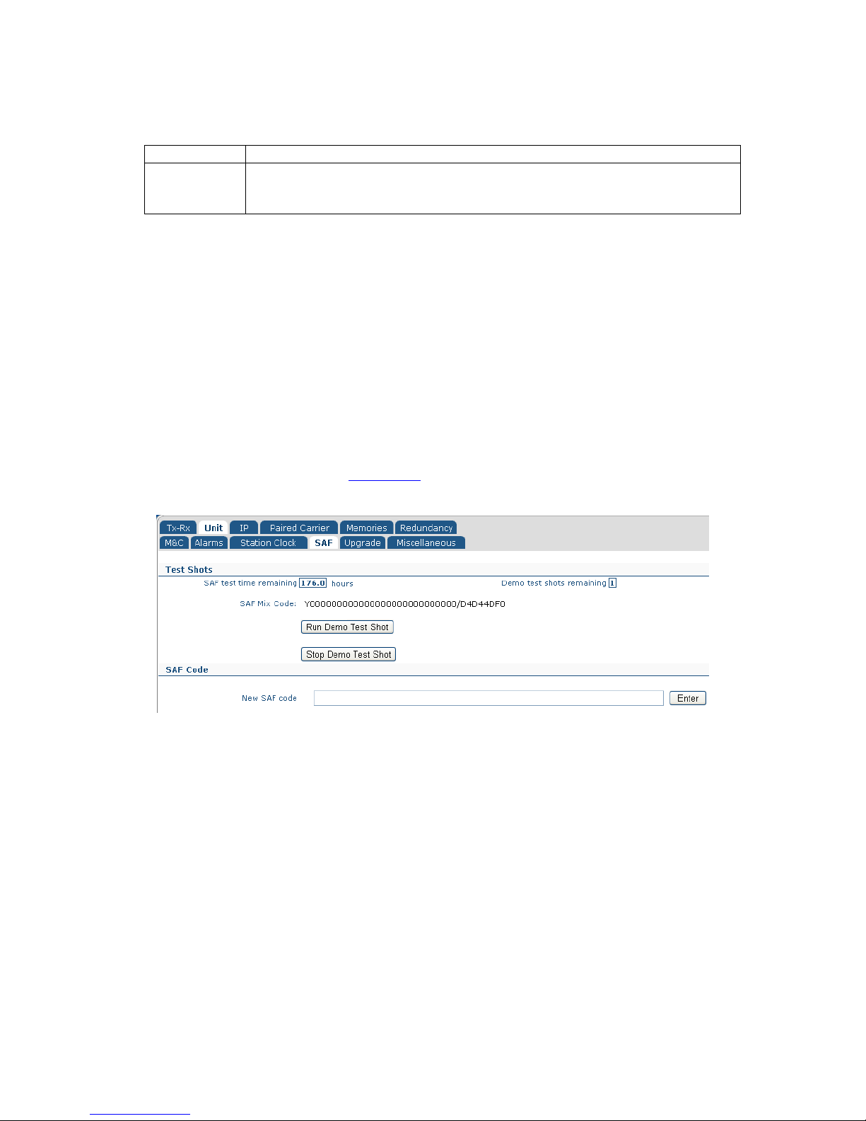
Q-Flex Satellite Modem Installation and Operating Handbook
6-42
Description: This must reflect the actual frequency of the station clock input as the
modem does not automatically measure the frequency. It is used by the
modem in programming the terrestrial interface clocking logic.
Table 6-49 Station Clock Frequency (when locking the high-stabiliy oscillator)
6.2.11.3 Locking the High-Stability Oscillator to the Station Clock
This is an On/Off control that determines whether the modem’s internal high-stability
oscillator is slaved to the station clock input. The high-stability oscillator is used in carrier
and BUC/LNB control. It therefore provides a way of extending system clock
synchronization to ancilliary equipment beyond the satellite modems.
6.2.12 Edit->Unit->SAF Screen
The Edit->Unit->SAF screen is shown in Figure 6-17. The concept of Software Activated
Features (SAF) is explained in Section 7-4.
Figure 6-17 Edit->Unit->SAF Screen
This screen displays:
• The remaining time period before any temporarily-enabled SAF features time out.
• The number of unused test shots remaining. A test shot enables all of the modem
features for a 10-day period (subject to suitable hardware being fitted and with
some exceptions).
• The SAF Mix Code, which is a number that represents all of the features that have
been permanently enabled on the modem.
The Run Demo Test Shot button is used to start a 10-day activation of the modem’s SAF
features.
The Stop Demo Test Shot button is used to terminate the temporary activation of the
modem’s SAF features. Any remaining time of the test period is lost.
Page 73

Q-Flex Satellite Modem Installation and Operating Handbook
6-43
The New SAF code edit box is used to enter a code provided by Paradise that unlocks
additional modem features. When unlocked, the features immediately become available.
The act of unlocking SAF features will not itself interfere with any services being provided
by the modem. Entering a code of ‘0’ will enable a test shot.
6.2.13 Edit->Unit->Upgrade Screen
The Edit->Unit->Upgrade screen is shown in Figure 6-18. This allows the modem’s
software to be upgraded (and downgraded). This can also be done via the front-panel
menus and a USB memory stick.
Figure 6-18 Edit->Unit->Upgrade Screen
The latest software can be found under Downloads on the Paradise company web site at
http://www.paradisedata.com. The software should be downloaded from the web site to a
temporary location that can be accessed by the browser and modem.
Using the Open button, it is necessary only to browse to the location of the upgrade file
and open the file. During the upgrade process the modem will drop any service that it is
providing.
Feedback on the progress of the upgrade, which typically takes around two minutes, is
provided on the screen. The modem will restart automatically when the upgrade is
complete and will resume operation using the same configuration as prior to the upgrade.
A remote modem can be upgraded over the satellite link by browsing to the remote
modem’s IP address and following the same upgrade process. Note that the speed of the
upgrade is dependent on the bandwidth available over satellite. An approximate time can
be worked out by comparing the size of the upgrade file with the bandwidth available.
In the event that an upgrade is unsuccessful then the modem will revert to a backup
version of software. This will normally be the same version as the software that the
modem shipped from the factory with. However, it is possible to set the fallback software
to any version (please consult Technical Support for further details).
To revert to the backup version of software in the modem, hold down the MAIN key at
power-up, then when the menu appears press 5 (this is a hidden menu option). This
Page 74

Q-Flex Satellite Modem Installation and Operating Handbook
6-44
boots the modem from a backup copy of the software stored when the modem was
manufactured. Once the modem has been recovered then the standard upgrade process
can be repeated.
6.2.14 Edit->Unit->Miscellaneous->Time Screen
The Edit->Unit->Miscellaneous->Time screen is shown in Figure 6-19. This allows the
modem’s real time clock to be set. The modem incudes a battery and maintains the time
even when powered down. The modem will display a dialog box to confirm that the date
and time have been changed (however, this will be displayed very briefly and may not be
seen in every case).
Figure 6-19 Edit->Unit->Miscellaneous->Time Screen
6.2.1 Edit->Unit->Miscellaneous->Reset Screen
The Edit->Unit->Miscellaneous->Reset screen is shown in Figure 6-20. This allows the
modem to be reset, following confirmation.
Page 75
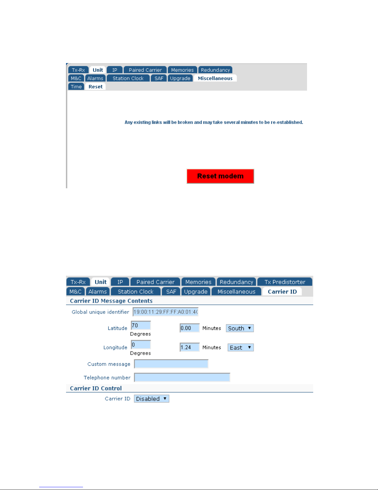
Q-Flex Satellite Modem Installation and Operating Handbook
6-45
Figure 6-20 Edit->Unit->Miscellaneous->Reset Screen
6.2.1 Edit->Unit->Carrier ID Screen
The Edit->Unit->Carrier ID screen is shown in Figure 6-21. This allows a low-power
spread spectrum signal containing user identification information to be superimposed on
the Tx carrier. When used with a suitable decoder, the information can be used to identify
the source of satellite carriers that are interfering with other satellite services.
Figure 6-21 Edit->Unit->Carrier ID Screen
Page 76

Q-Flex Satellite Modem Installation and Operating Handbook
6-46
6.2.1.1 Carrier ID Global Unique Identifier
The Carrier ID Global unique identifier is a unique ID for the modem. Its value is fixed
during the manufacturing process and cannot be changed. The unique identifier is
transmitted as part of the Carrier ID information allows the modem manufacturer and the
specific modem to be traced.
6.2.1.2 Carrier ID Latitude and Longitude
The Carrier ID Latitude and Longitude fields allow the user to enter the geographic
position of the modem. This information is transmitted as part of the Carrier ID and allows
a Carrier ID decoder to identify the location from which an interfering carrier is being
generated.
6.2.1.3 Carrier ID Custom Message and Telephone Number
The Carrier ID Custom message and Telephone number fields are optional. If entered,
this information will be transmitted as part of the Carrier ID signal and will be available for
viewing via a suitable Carrier ID decoder.
6.2.1.4 Carrier ID
This is an Enabled/Disabled control that controls the generation of the Carrier ID spread
spectrum signal. Carrier ID is an optional feature and can be made available on all Q
Series modems via a software upgrade. The Carrier ID feature is not provided as
standard and the Carrier ID SAF must therefore be activated on the modem for the
feature to be available on the menus.
6.2.2 Edit->IP Screen
The Edit->IP screen (shown in Figure 6-22) allows the following to be set up:
• Basic and advanced IP modes and features, such as bridging, routing, acceleration
and compression.
• The modem’s terrestrial and satellite traffic IP addresses.
• Miscellaneous IP features used for specialized modes of operation.
• Further tabs are available that allow the setup of advanced features (VCM
multistreaming and MPEG2 transport streams), traffic shaping (QoS) and static
routes.
Ethernet speed/duplex settings are available on the Edit->Unit->Interface screen.
Page 77

Q-Flex Satellite Modem Installation and Operating Handbook
6-47
Figure 6-22 Edit->IP Screen
6.2.2.1 IP Mode
Table 6-50 shows the IP mode options. The operation of the M&C and IP Traffic Ethernet
ports is summarized in Table 6-51.
Bridge mode In this mode the modem acts as an Ethernet bridge, preserving the
original Ethernet frames (including additional fields such as VLAN and
MPLS headers) over satellite.
Routing
mode
In this mode IP packets are forwarded based on the contents of the
modem’s routing table, which can be configured manually with static
routes or controlled dynamically by enabling dynamic routing. Dynamic
routing populates the routing table based on information forwarded by
other routers in the network. The modem operates as a two-port router in
this mode (with separate terrestrial and satellite IP addresses).
Trunking
mode
Trunking mode implements a Layer 2 bridge in hardware. This results in a
much higher packet handling capability (up to 500,000 packets per
second as opposed to a maximum of 150,000 packets per second when
in other modes). Because the processor is bypassed in this mode, jitter is
also minimised and typically registers as zero when measured with
Ethernet test equipment. ACM (and AUPC) can be used in Trunking mode
but other IP features such as TCP acceleration cannot be used because
they require the packets to be passed through the processor.
Table 6-50 IP Mode
Page 78

Q-Flex Satellite Modem Installation and Operating Handbook
6-48
Modem Settings
Ethernet Operation
Bridging
/Routing
Mode
M&C and IP
Traffic
Ethernet
Ports
TCP
Acceleration
Operation of
M&C
Ethernet
Port
Operation of
IP Traffic
Ethernet
Port
Bridging Bridged Off M&C address
shared with IP
Traffic port; M&C
traffic will be
bridged over
satellite as required
IP Traffic address
not used; port is
addressed via
M&C address;
traffic will be
bridged over
satellite as
requried
Bridging Bridged On This combination of modem settings is
illegal (M&C port will be automatically
removed from bridge)
Bridging Not bridged Off M&C port has
dedicated address;
M&C traffic will not
be bridged over
satellite
IP Traffic port has
dedicated address;
traffic will be
bridged over
satellite as
required
Bridging Not bridged On M&C port has
dedicated address;
M&C traffic will not
be bridged over
satellite; modem
gateway is applied
to M&C subnet
IP Traffic address
not used; IP Traffic
port dedicated to
satellite traffic only,
which will be
accelerated and
bridged over
satellite as
required
Routing Bridged Off This combination of modem settings is
illegal (M&C port will be automatically
removed from bridge)
Routing Bridged On This combination of modem settings is
illegal (M&C port will be automatically
removed from bridge)
Routing Not bridged Off M&C port has
dedicated address,
which must be on a
different subnet to
IP Traffic port; M&C
traffic will be routed
over satellite as
required
IP Traffic port has
dedicated address;
traffic will be
routed over
satellite as
required
Modem gateway applied to either port as
specified by subnet
Routing Not bridged On M&C port has
dedicated address,
which must be on a
different subnet to
IP Traffic port; M&C
traffic will be routed
and accelerated
over satellite as
required
IP Traffic port has
dedicated address;
traffic will be
routed and
accelerated over
satellite as
required
Modem gateway applied to either port as
specified by subnet
Table 6-51 Ethernet Port Operation
Page 79

Q-Flex Satellite Modem Installation and Operating Handbook
6-49
6.2.2.2 Bridge M&C
This is an On/Off control that determines whether the two RJ45 Ethernet ports on the
modem are bridged together or whether they have separate IP addresses allocated to
them.
When the Remote M&C Ethernet port is out of the bridge then satellite IP traffic and M&C
traffic are processed separately and therefore the two modem Ethernet connectors are no
longer interchangeable. Care should be taken in selecting this mode for a remote modem
since if the cables have been incorrectly fitted then it could result in M&C communications
with the remote modem being lost.
When the Remote M&C Ethernet port is bridged to the satellite IP Traffic port then the two
modem Ethernet ports act as a two-port Ethernet switch.
6.2.2.3 TCP Accleration
This is an On/Off control that controls TCP acceleration.
Packets received by the modem will be either bridged or routed as determined by the IP
mode setting.
When on, TCP packets are processed by a Performance Enhancing Proxy (PEP) that
overcomes performance problems associated with using standard TCP over satellite.
Configuring TCP Acceleration
• Bridging Mode
In order to make it easier to set up, TCP acceleration does
not use an IP address for the IP traffic port when used in
bridging mode. The M&C Ethernet port cannot be bridged to
the IP Traffic port when using bridged TCP acceleration.
M&C control must be provided via a separate subnet to that
used for satellite traffic. The modem gateway is applied to
the M&C subnet.
• Routing Mode
In this mode, the M&C Ethernet port and IP Traffic port have
dedicated addresses and must be on separate subnets. All
packets on both ports will be accelerated and passed over
satellite as required. The modem gateway is applied to
either the M&C subnet or IP Traffic subnet as specified by
the user.
Page 80

Q-Flex Satellite Modem Installation and Operating Handbook
6-50
6.2.2.4 Round-trip Satellite Delay
Range: 0ms to 9999ms; step size: 1ms
Description: This sets a satellite round-trip delay that is used in conjunction with TCP
acceleration. It controls the size of the modem’s internal packet buffer to
match the bandwidth-delay product for the link (i.e. the link’s data capacity
multiplied by the end-to-end delay). This helps to maintain the throughput
at its maximum level when TCP acceleration is on.
Table 6-52 Round-trip Satellite Delay
6.2.2.5 Header Compression
This is an On/Off control that controls header compression.
IP, UDP and RTP header compression is supported in accordance with the Robust
Header Compression (ROHC) standard RFC 3095 (profiles 2 and 3). ROHC typically
reduces the 40 bytes of IP, UDP and RTP header, which is typically used with Voice over
IP data, down to between 1 and 3 bytes. Ethernet header compression is also supported
in addition and this reduces 14 bytes of Ethernet frame down to typically 1 byte. Overall
savings from compression from both types of compression (e.g. for a G.729 voice stream)
can be as high as 60%.
When header compression is on, Ethernet, UDP, TCP, RTP and IP packet headers are
compressed in order to save satellite bandwidth. The relative bandwidth saving is greater
for smaller packets.
The compressed packets will be either bridged or routed as determined by the IP mode
setting.
Selective compression of packets can be controlled via the Edit->IP->Header
Compression screen, which allows routes to be added.
6.2.2.6 Payload Compression
This is an On/Off control that controls header compression.
When payload compression is on, the payload of IP packets are compressed in order to
save satellite bandwidth.
The compressed packets will be either bridged or routed as determined by the IP mode
setting.
6.2.2.7 ACM Mode
Table 6-47 lists the modes available with respect to Adaptive Coding and Modulation
(ACM). ACM converts any unused link margin into additional IP throughput.
Page 81

Q-Flex Satellite Modem Installation and Operating Handbook
6-51
Off When using DVB-S2, this switches ACM off in both transmit and receive.
On This switches ACM on in both transmit and receive.
When ACM is on, the choice of modulation and FEC rate (modcod) in the
transmit path is dynamically matched to the reported Es/No from the
remote modem. Symbol rate and carrier power are unchanged but data
rate will vary with the choice of modcod.
The modem will automatically insert regular Es/No information into the
return carrier (with no material effect on bandwidth). This is used to
control the carrier modcod selection of the other modem, should it have
ACM enabled.
Monitor This switches ACM on in receive only. This causes the modem to
automatically insert regular Es/No information into the return carrier,
which is used by the distant modem to determine the choice of transmit
modcod.
A secondary function that is switched on is as a test mode that simulates
ACM being on but does not actually change modcod. Instead, it records
what modcods would have been selected if ACM was actually on,
including recording the time, remote Es/No and the data rate. This allows
ACM to be tested in a non-intrusive way on a live link and also allows any
projected bandwidth savings to be confirmed prior to going live.
The record of ACM modcod changes can be viewed graphically on the
ACM graph (under View->Graphs->IP->ACM) or as text in the system log
(under View->Log).
Table 6-53 ACM Mode
Page 82

Q-Flex Satellite Modem Installation and Operating Handbook
6-52
6.2.2.8 ACM Rain Fade Margin
Range: 0dB to 9.9dB; step size: 0.1dB
Description: This sets a margin used in the ACM control process when making
decisions on what modcod to select based on the current Es/No reading
of the remote modem. By setting the ACM rain fade margin to a non-zero
value, ACM operation will cope with a faster rate of rain fade without
losing demodulator lock than would otherwise be the case.
Note that the ACM control process has its own non-configurable operating
margin built in (which will cope with Es/No changes of up to 1dB/s) and
therefore the ACM rain fade margin should be used only on links that
have the potential for particularly severe rain fades.
Setting an ACM margin that is higher than necessary will reduce the
benefits of using ACM since non-optimal modcods may be used due to
the need to maintain a larger margin between the actual Es/No and the
Es/No required by the dynamically selected modcods.
Table 6-54 Round-trip Satellite Delay
6.2.2.9 M&C IP Address, Subnet Mask & Modem IP Gateway
M&C
IP Address
Default:
10.0.70.1
Description: This sets the IP address for remote control. When the M&C and traffic
Ethernet ports are bridged together then this address is used for both
M&C purposes and satellite traffic.
An IP address of 0.0.0.0 causes the modem to request its IP address from
a Dynamic Host Control Protocol (DHCP) server on the network,
removing the need to allocate static IP addresses to each modem. The
allocated IP address can be seen on the View->Unit screen. A request to
the DHCP server is made every minute until a reply is received.
When IPv6 support is selected on the menus then additional address
entry options are provided.
When changing the IP address, devices communicating with the modem
may take several minutes to recognize the new address unless the
Address Resolution Protocol (ARP) table on the device is flushed.
M&C IP
Subnet Mask
Default:
255.255.0.0
Description: Sets the remote control port IP subnet mask.
Page 83

Q-Flex Satellite Modem Installation and Operating Handbook
6-53
Modem IP
Gateway
Default:
0.0.0.0
Description: Sets the IP address of a default gateway. The gateway represents the
‘next hop’ destination, which is normally the address of a router, for
packets destined for somewhere other than the local network. This is
used whenever the IP mode is set to Routing. An address of 0.0.0.0
means that the gateway is not set.
Table 6-55 M&C IP Address, Subnet Mask & Modem IP Gateway
6.2.2.10 Traffic/Satelite IP Addresses and Subnet Masks
Traffic
IP address
This sets the IP address for the modem’s IP Traffic port. (DHCP is not
supported for this address and therefore an address must be manually
entered.)
When IPv6 support is selected on the menus then additional address
entry options are provided.
Traffic
IP subnet
mask
This sets the subnet mask for the modem’s IP Traffic port.
Satellite
IP address
This sets the IP address for the modem’s satellite IP port. This is only
used when in routing mode, when the modem acts as a two-port router.
Satellite
IP subnet
mask
This sets the subnet mask for the modem’s satellite IP port.
Table 6-56 Traffic/Satellite IP Address & Subnet Mask
Page 84

Q-Flex Satellite Modem Installation and Operating Handbook
6-54
6.2.2.11 IP Encapsulation Type
MPE This selects Multi-Protocol Encapsulation (MPE) as the protocol for
encapsulating IP packets and Ethernet frames for transmission over
satellite when using DVB-S2. This protocol is widely supported and is
therefore useful for interoperability. It adds an overhead of around 10%.
ULE This selects Unidirectional Lightweight Encapsulation (ULE) as the
protocol for encapsulating IP packets and Ethernet frames for
transmission over satellite when using DVB-S2. It adds an overhead of
around 5% to 7%.
PXE This selects proprietary Paradise XStream Encapsulation (PXE) as the
protocol for encapsulating IP packets and Ethernet frames for
transmission over satellite when using DVB-S2. It adds an overhead of
around 2%.
Table 6-57 (DVB-S2) IP Encapsulation Type
6.2.2.12 Encapsulation PID
Range: 0 to 8190; step size: 1
Description: When encapsulating Ethernet frames or IP packets into MPEG2 packets
as part of a DVB-S2 IP service, this specifies the Packet ID (PID) value to
be entered into the MPEG2 packets that are being created. Note that the
value is in decimal, not hexadecimal.
The PID can then be used for filtering MPEG2 packets on the receive
side.
The encapsulation PID must be left at its default value of 970 if DVB-S2
AUPC or DVB-S2 ACM is being used.
Table 6-58 Encapsulation PID
Page 85

Q-Flex Satellite Modem Installation and Operating Handbook
6-55
6.2.2.13 MPE MAC Address
Format
example:
00:11:29:00:F0:23
Description: For DVB-S2 IP services, this is used for filtering of Multi-Protocol
Encapsulation (MPE) packets on the receive side. The receiver will filter
against whatever MAC address has been provided, which can therefore
be a virtual MAC address rather than the receiver’s address.
(There is currently no equivalent modulator support to allow a specific
MAC address to be added to MPE packets. A Paradise modulator will
always set the MPE MAC address to all zeros in routing mode and to the
destination MAC address of the incoming Ethernet frame when in bridging
mode.)
Table 6-59 MPE MAC Address
6.2.2.14 Weighted QoS
This is an On/Off control that controls IEEE 802.1p packet prioritization. It is mutually
exclusive with the traffic shaping feature and when traffic shaping is enabled then
strict/fair queuing will be automatically switched off.
This allows for eight classes of data to be specified as part of a three-bit field within the
Layer 2 IEEE 802.1q VLAN header. The packets must already be tagged at the point of
entry to the modem. Priority 7 is typically used for network-critical traffic such as dynamic
routing protocol packets; priorities 5 and 6 for video and voice, etc. The modem uses the
priority tag to decide how to process each packet. The options are:
• Strict-priority queuing: packets are queued for transmission based solely on
their priority with the highest always being sent first. Strict-priority queuing is
active whenever Weighted QoS is set to Off.
• Fair-weighting queuing: higher-priority packets are transmitted first but
lower-priority packets are given a percentage of the bandwidth. Fair-weighting
queuing is active whenever Weighted QoS is set to On.
The implementation of IEEE 802.1p packet prioritization is as follows:
• The eight QoS priority levels are mapped to three TCP/IP queues in the
modem.
• Packets with highest QoS priority (level 7) are sent to high priority TCP/IP
queue.
• Delay-sensitive packets (QoS levels 6 and 5) are sent to the medium priority
queue.
• The remainder (QoS levels 4 to 0) are sent to the low priority TCP/IP queue.
• For strict-priority queuing, all packets in the high-priority queue are processed
before any in the medium-priority queue, which in turn are processed before
any in the low-priority queue.
Page 86

Q-Flex Satellite Modem Installation and Operating Handbook
6-56
For fair-weighting queuing, for every four packets sent from the high-priority queue, two
are sent from medium-priority queue and one from the low-priority queue.
6.2.2.15 IPv4/IPv6 Mode
IPv4 only This enables the entry and display of IP addresses in IPv4 format only.
The modem will bridge IPv4 and IPv6 packets when in IPv4 mode but will
route only IPv4 packets.
IPv4 and
IPv6
This enables the entry and display of IP addresses in either IPv4 format or
IPv6 format.
The modem will bridge and route both IPv4 and IPv6 packets in this
mode.
Table 6-60 IPv4/IPv6 Mode
6.2.2.16 M&C and IP Traffic Ethernet Speed/Duplex
Table 6-61 lists the different Ethernet speed and duplex settings for the modem’s
Ethernet interfaces. The M&C interface and IP traffic interface can be set independently
of each other. Changes will be effective immediately but when an auto-negotiated mode
is selected then any Ethernet connection will be briefly disconnected while the change
takes effect. The Auto setting is recommended for normal use but because Ethernet autonegotiation varies between different manufacturers it may be necessary to fix the speed
and duplex in some circumstances. The type of cable (crossover or straight) is always
automatically sensed by the modem, which will work with both.
Page 87

Q-Flex Satellite Modem Installation and Operating Handbook
6-57
Auto In this mode the modem will auto-negotiate the Ethernet speed
and duplex settings.
10M half duplex
In this mode the modem will auto-negotiate the Ethernet speed
and duplex settings but as part of the negotiation will ‘advertise’
10Mbps half duplex as the only option available.
10M full duplex
The modem will auto-negotiate the Ethernet speed and duplex
settings but as part of the negotiation will ‘advertise’ 10Mbps full
duplex as the only option available.
100M half duplex The modem will auto-negotiate the Ethernet speed and duplex
settings but as part of the negotiation will ‘advertise’ 100Mbps half
duplex as the only option available.
100M full duplex The modem will auto-negotiate the Ethernet speed and duplex
settings but as part of the negotiation will ‘advertise’ 100Mbps full
duplex as the only option available.
1000M half duplex The modem will auto-negotiate the Ethernet speed and duplex
settings but as part of the negotiation will ‘advertise’ 1000Mbps
half duplex as the only option available.
1000M full duplex The modem will auto-negotiate the Ethernet speed and duplex
settings but as part of the negotiation will ‘advertise’ 1000Mbps full
duplex as the only option available.
10M half duplex
(fixed)
The modem’s Ethernet interfaces will be fixed to 10Mbps half
duplex operation.
10M full duplex
(fixed)
The modem’s Ethernet interfaces will be fixed to 10Mbps full
duplex operation.
100M half duplex
(fixed)
The modem’s Ethernet interfaces will be fixed to 100Mbps half
duplex operation.
100M full duplex
(fixed)
The modem’s Ethernet interfaces will be fixed to 100Mbps full
duplex operation.
1000M half duplex
(fixed)
The modem’s Ethernet interfaces will be fixed to 1000Mbps half
duplex operation.
1000M full duplex
(fixed)
The modem’s Ethernet interfaces will be fixed to 1000Mbps full
duplex operation.
Table 6-61 Ethernet Speed/Duplex
Page 88

Q-Flex Satellite Modem Installation and Operating Handbook
6-58
6.2.2.17 Ethernet MTU
Range: 2,000 bytes to 10,000 bytes; step size: 1 byte
Description: This controls the Ethernet Maximum Transmission Unit (MTU) size, which
defines the largest Ethernet frame that can be handled by the modem in
bridging mode without fragmentation into smaller frames.
Table 6-62 Ethernet MTU
6.2.3 Edit->IP->Advanced Screen
The Edit->IP-Advanced screen (shown in Figure 6-23) allows the following to be set up:
• IP buffers used in the process of receiving terrestrial IP packets and transmitting
them over satellite. The buffers influence the quality of service with respect to
overall packet delay and whether packets are dropped or buffered during periods
of congestion.
• Miscellaneous settings used in specific modes of operation, including operation of
the 4-port Ethernet switch, internal VLAN tagging inside the modem and point-tomultipoint operation.
• MPEG2 transport stream processing, when using the ASI interface, or IP over
DVB (where several MPEG2 transport stream packets are included inside one IP
packet).
• Multiple streams, when using DVB-S2 Variable Coding and Modulation (VCM). Two
streams are supported (two ASI streams, or one ASI stream plus IP).
Page 89

Q-Flex Satellite Modem Installation and Operating Handbook
6-59
Figure 6-23 Edit->IP->Advanced Screen
6.2.3.1 Terrestrial Buffer Size
The terrestrial buffer is used to buffer IP packets coming into the IP terrestrial ports for
transmission over satellite. Satellite delay and the quality of the service in general can be
controlled by the size of this buffer in conjunction with setting the size of the satellite
buffer. The buffer should be set large enough to accommodate bursts of packets being
received by the modem. Setting the buffer larger than necessary could result in large
packet delays building up should more packets be sent to the modem than can be
transmitted.
The optimal size for the buffer depends on the link data rate, the packet sizes, the
number of packets and the specific application (some applications being able to tolerate
Page 90

Q-Flex Satellite Modem Installation and Operating Handbook
6-60
packet loss and/or delays more than others). When the buffer is full then received packets
will be dropped until space in the buffer is freed up.
It is generally desirable for the terrestrial buffer to be set so that packets are not dropped
unnecessarily before they have been assessed by the traffic shaper as to priority, etc. At
the same time, a large buffer could result in stale data being kept, which it might be better
to drop by making the buffer smaller so that only the most recent data is kept in an
overload situation.
6.2.3.2 Satellite Buffer Size
The satellite buffer is used to buffer IP packets ready for transmission over satellite. The
buffer is situated after all internal packet processing has been completed, including traffic
shaping and encapsulation. Satellite delay and the quality of the service in general can be
controlled by the size of this buffer. The buffer should be set large enough to even out
peaks and troughs in throughput that would result from setting an extremely small buffer.
Setting the buffer larger than necessary could result in large packet delays building up
should more packets be available than can be transmitted. The traffic shaper can be used
to ensure that the combined output from all classes of traffic does not exceed the
available satellite bandwidth, even when ACM (which dynamically adjusts the data rate) is
active.
The optimal size for the buffer depends on the link data rate, the packet sizes, the
number of packets and the specific application (some applications being able to tolerate
packet loss and/or delays more than others). When the buffer is full then new packets for
transmission will be dropped until space in the buffer is freed up.
6.2.3.3 Ethernet Address Learning
By default, Ethernet (or MAC) address learning is not enabled on the modem. This helps
to protect against the possibility of traffic storms caused by inadvertent loops in the
network.
However, when the 4-port Ethernet expansion switch is fitted to the modem then it is
strongly recommended that Ethernet address learning is enabled. If address learning is
disabled when the 4-port switch is fitted then traffic sent to one port will also be flooded
onto all other ports since the modem will be unaware of which devices are connected to
which switch port. While a small amount of flooding is acceptable as a means of
automatically detecting and adapting to changes in the network, it is undesirable to do it
all the time. This problem does not arise when only a single IP traffic port is available on
the modem.
Page 91

Q-Flex Satellite Modem Installation and Operating Handbook
6-61
6.2.3.4 Point-to-multipoint Mode
The modem can be used in a point-to-multipoint mode where the hub modem sends a
shared outbound to several remotes. The inbounds from the remotes are processed by
individual demodulators.
Hub Sets up a modem at the hub to be part of a point-to-multipoint
system. All modems at the hub site, even if configured for Rx
operation only, should be set to this mode (or one of the other hub
modes described below).
Remote Sets up a modem at a remote site to work point-to-multipoint. All
remote modems that form part of a point-to-multipoint system
should be set to this mode (or one of the other remote modes
described below).
Hub + TCP
acceleration
This enables point-to-multipoint TCP acceleration. The hub Tx
modem should be set to this mode and VLAN filtering should also
be enabled on this modem. Note that hub Rx-only modems in a
point-to-multipoint TCP acceleration system should be set to Hub
mode (not Hub + TCP Acceleration) and that the Rx-only modems
should have VLAN filtering disabled.
Remote + TCP
acceleration
For remote modems, this enables point-to-multipoint TCP
acceleration. All remote modems should be set to this mode and
VLAN filtering should also be enabled.
Hub + Bridged TCP
acceleration
This mode is similar to Hub + TCP acceleration but preserves the
original Ethernet frames over satellite (allowing, for example, s
TCP acceleration of any number of VLANs and acceleration of
MPLS streams). In this mode, for ease of use, there is no need to
enter an IP address for the IP Traffic port. Since the TCP packets
are bridged over satellite, there is no need to set up static routes
or gateways.
Remote + Bridged
TCP acceleration
This mode is similar to Remote + TCP acceleration but preserves
the original Ethernet frames over satellite. The IP Traffic port does
not have an IP address in this mode. Static routes and gateways
are not required.
Table 6-63 Point-to-multipoint Mode
6.2.3.5 VLAN Filtering
VLAN filtering is used in point-to-
multipoint mode only, in order to ensure that just the
relevant packets are processed at each remote site, with all non-
relevant packets being
discarded. The hub modem will automatically add
the appropriate VLAN tags to the
packets to to be transmitted to the remote modems. Filtering out irrelevant packets at the
remote sites stops them circulating in the wider network and potentially causing packet
storms.
Page 92

Q-Flex Satellite Modem Installation and Operating Handbook
6-62
When VLAN filtering is disabled, V
LAN tags are not generated or removed by the
modem. This means that no filtering of traffic based on VLAN ID takes place. Since each
remote modem receives the same broadcast traffic, a device such as a router must be
present to filter out any traffic that is intended only for the other remote modems.
When VLAN filtering is enabled, each remote modem can be assigned a VLAN id which
is used by the hub to tag each packet destined for any device attached to a network off
that particular remote modem. The tags
are added by the hub Tx modem and removed
by the remote modem. The remote modem uses the tag to filter out unwanted data that
has been broadcast indiscriminately to all remote modems.
Setting a value for the VLAN ID is required for remote modems only. Ass
igning a VLAN
ID to a hub modem has no effect. The VLAN ID should be used to uniquely identify each
remote modem. It is used to filter wanted from unwanted IP packets in point-to-
multipoint
systems where there is a direct return path. The VLAN IDs of remot
e modems are
automatically learnt by the hub Tx modem and all traffic destined for a particular remote
modem will be tagged at the hub. The VLAN tags are removed by the remote modems
prior to onward transmission.
6.2.3.6 Null Packet Insertion
Off When using the ASI or IP terrestrial interfaces with MPEG2
transport stream packets, any MPEG2 null packets within the
incoming terrestrial data stream will be left untouched (and will
therefore be transmitted over satellite) when null packet insertion
is set to Off.
On When null packet insertion is set to On, any MPEG2 null packets
within the data stream will be stripped out and discarded. Since
null packets contain no useful data then discarding them can save
bandwidth.
Strip & Insert The strip and insert option strips all MPEG2 null packets from the
incoming terrestrial data stream. It also inserts MPEG2 null
packets into the stream of packets transmitted to satellite in such a
way as to match exactly the required transmit symbol rate in the
event that there are less packets than required to fill the satellite
pipe.
Table 6-64 Null Packet Insertion
6.2.3.7 PCR Restamping
PCR restamping is an On/Off control that controls whether MPEG2 Program Clock
Reference (PCR) timestamps in received MPEG2 transport stream packets (via the ASI
or IP interfaces) are adjusted for any delay introduced by the modem. By adjusting the
Page 93

Q-Flex Satellite Modem Installation and Operating Handbook
6-63
timestamps as required, potential jitter in the play out of the packets at the
receiver/decoder can be eliminated.
6.2.3.8 MPEG Over IP Type
UDP/TS This indicates that the MPEG2 transport stream packets are
encapsulated into into IP packets using the UDP protocol.
UDP/RTP/TS This indicates that the MPEG2 transport stream packets are
encapsulated into into IP packets using the UDP and RTP
protocols.
Table 6-65 MPEG Over IP Type
When sending MPEG2 packets encapsulated inside IP packets, the modem can reduce
the satellite transmission overhead by removing the IP headers and sending only the
MPEG2 packets. On the receive side, the MPEG2 packets are encapsulated back into IP
packets, using IP address and port number information entered by the user. When
decapsulating and encapsulating MPEG2 packets, the modem needs to know whether
the IP packets contain just UDP headers, or UDP and RTP headers.
6.2.3.9 Destination Address and Destination Port
Destination
address
When using MPEG2 over IP, the IP packet wrapper is discarded in order
to save satellite bandwidth. The user-entered destination address is
therefore used on the receive side in order to recreate a copy of the
original IP packet.
Destination
port
The destination UDP port number is used in a similar way to to the
destination address above, when creating a copy of the original IP packet
in order to wrapper received MPEG2 packets.
Table 6-66 Destination Address & Destination Port
6.2.3.10 Local Multicast Address and Local Port
Local
multicast
address
When using MPEG2 over IP, the modem can listen on a local multicast
address in order to detect packets to be sent over satellite.
Page 94

Q-Flex Satellite Modem Installation and Operating Handbook
6-64
Local port The local port number is used in conjunction with the local multicast
address above in order to fully define the address and port number the
modem should listen on for incoming multicast packets.
Table 6-67 Local Multicast Address and Local Port
6.2.3.11 Stream Tx/Rx Terrestrial Interface
Off When the terrestrial interface is off then then the particular stream is not
used.
ASI-1, ASI-2,
ASI-3
This takes the stream input from, or directs the stream output to, the
specified port on the ASI card.
IP This takes the stream input from, or directs the stream output to, the IP
traffic interface
Table 6-68 Stream Tx/Rx Terrestrial Interface
6.2.3.12 Stream Tx/Rx Identifier
Range: 0 to 25; step size: 1
Description: In the context of DVB-S2 Variable Coding and Modulation (VCM) used to
support multiple streams, the stream identifier corresponds to the DVB-S2
Input Stream Identifier (ISI) used to differentiate each unique stream in
order to be able to correlate transmitted and received streams.
Table 6-69 Stream Tx/Rx Identifier
6.2.3.13 Stream Tx Data Rate
Range: 0.2Mbps to 160.0Mbps; step size: 0.000001Mbps
Description: The stream data rate is the maximum number of data bits that the modem
will process in relation to the selected terrestrial interface.
Table 6-70 Stream Tx Data Rate
6.2.3.14 Stream Tx Modulation
Each stream can use any of the supported DVB-S2 modulations, as listed in Table 6-71.
(In receive, the modulation type is detected automatically.)
Page 95

Q-Flex Satellite Modem Installation and Operating Handbook
6-65
DVB-S2
QPSK: 1/4, 1/3, 2/5, 1/2, 3/5, 2/3, 3/4, 4/5, 5/6, 8/9, 9/10
8PSK: 3/5, 2/3, 3/4, 5/6, 8/9, 9/10
16APSK: 2/3, 3/4, 4/5, 5/6, 8/9, 9/10
32APSK: 3/4, 4/5, 5/6, 8/9, 9/10
Table 6-71 Tx Modulation and FEC Code Rates
6.2.3.15 Stream Tx FEC Code Rate
Each stream can use any of the supported DVB-S2 FEC code rates listed in Table 6-58.
(In receive, the FEC code rate is detected automatically.)
6.2.3.16 Stream Tx Pilot Tones
Pilots are an On/Off control that controls whether DVB-S2 pilots, which are unmodulated
symbols, are injected into the carrier on a regular basis in order to help the demodulator
lock onto the carrier. The pilots are 36 symbols long and are injected every 1440
symbols, representing an additional overhead of around 2.4%.
6.2.3.17 DVB-S2 Tx Frame Size
Short This represents a frame size of 16,200 bits per frame.
Normal This represents a frame size of 64,800 bits per frame. This is more
bandwidth efficient than short frames but has four times the
latency. As a guideline, short frames have a latency of around
25ms at 1Mbps, whereas the latency for normal frames is around
100ms at 1Mbps. The latency will halve as data rate doubles.
Table 6-72 DVB-S2 Tx/Rx Frame Size
6.2.3.18 Tx/Rx Symbol Rate
The calculated transmit and receive symbol rates, aggregated for all streams, are
displayed in order to allow the user to verify that the streams have been set up correctly.
6.2.4 Edit->IP->QoS Screen
Traffic shaping is described in Section 7.8.9
Page 96

Q-Flex Satellite Modem Installation and Operating Handbook
6-66
6.2.5 Edit->IP->Static Routes Screen
The Edit->IP->Static Routes screen, shown in Figure 6-24, allows up to 16 static routes
to be added.
Figure 6-24 Edit->IP->Static Routes Screen
Each route consists of a destination IP address, subnet mask and a gateway address.
The Add button must be selected in order to enable each route.
The Del button is used to delete individual routes.
The Click to apply routes button must be selected to apply the static routes before
navigating away from the web page.
Page 97

Q-Flex Satellite Modem Installation and Operating Handbook
6-67
The Show Routes button can be used to display the underlying operating system ‘route
add’ commands applied to the TCP/IP stack, thereby providing confirmation of the active
static routes.
6.2.6 Edit->IP->Header Compression Routes Screen
The Edit->IP->Header Compression Routes screen, shown in Figure 6-25, allows up to
16 static routes to be added. These determine which packets header compression is
applied to. Compression is both transparent and lossless.
Figure 6-25 Edit->IP->Header Compression Routes Screen
Page 98

Q-Flex Satellite Modem Installation and Operating Handbook
6-68
Each route consists of a destination IP address and subnet mask. The Add and Del
buttons enable and disable each route, respectively. Note that routes can be applied even
when in bridging mode.
The Click to apply routes button must be selected to apply the header compression
routes before navigating away from the web page.
The Show Routes button can be used to confirm the active header compression routes.
6.2.7 Edit->Paired Carrier Screen
The Edit->Paired Carrier screen (shown in Figure 6-26) is used to set up the Paired
Carrier™ function, which allows two carriers to be overlapped in the same space segment.
Figure 6-26 Edit->Paired Carrier Screen
6.2.7.1 Paired Carrier Enable
This is an On/Off control that enables and disables Paired Carrier™ operation.
Deployment recommendations for first-time use of Paired Carrier™ are provided in
the information box on the next page.
When switched on, the modem expects the received signal to consist of two overlapped
carriers utilizing the same space segment. When active, a copy of the modem’s
transmitted signal will be stored in memory and the Paired Carrier™ signal processing
algorithm will attempt to match this with the composite return signal, in order to subtract
the unwanted near signal leaving just the far carrier.
Prior to enabling Paired Carrier™ it is necessary to set up the delay to satellite as in the
following menu options.
Note that there are no other control settings that are specific to Paired Carrier™
operation – other settings used by the Paired Carrier™ algorithm such as centre
frequency and sweep width form part of the normal setup of the modem even for nonoverlapped carriers and work in the same way. The cancellation bandwidth itself is
automatically deduced by the modem from the larger of the transmit and receive symbol
rates and roll-off factors (i.e. occupied bandwidth).
Page 99

Q-Flex Satellite Modem Installation and Operating Handbook
6-69
Table 6-73 indicates the circumstances under which modem signal inversions are
required in relation to Paired Carrier™ operation.
P
aired
Carrier
Working?
BUC LNB
Tx Modem
Inversion
Rx Modem
Inversion
Yes Non Inverting Non Inverting No No
Yes Non Inverting Inverting No Yes
Yes Inverting Inverting No No
No Inverting Non Inverting N/A N/A
Table 6-73 Paired Carrier™ Spectral Inversion Control
PLEASE READ THE FOLLOWING INFORMATION FOR FIRST-TIME
SETUP OF A PAIRED CARRIER™ LINK.
In relation to Paired Carrier™, generally there are no restrictions on how
the overlapped carriers are brought up and the satellite link is established.
However, the following guidelines may be useful in proving correct Paired
Carrier™ operation as part of the overall initial link deployment process.
Once correct operation is established then Paired Carrier™ can be
switched on and off or reconfigured just like any other modem feature.
You must get each link working correctly as a normal link prior to
switching Paired Carrier™
on! You must ensure that there is no spectral
inversion in the RF chain – if there is then this must be corrected by reinverting it for Paired Carrier™ operation to work – see the above table.
1. Ensure Paired Carrier™ is switched off (via the Paired Carrier enable
setting on the Edit->Paired Carrier menu).
2. Before starting, it is strongly recommended to prepare for a BER data
transparency test, using data test sets connected to each modem, or
using the modem internal PRBS BER test feature, which can be
temporarily enabled if necessary.
3. Configure both modems for identical services, including the same Tx
and Rx frequencies.
Different PRBS test patterns must be used in each direction (e.g. for
Modem 1 Tx to Modem 2 Rx use 2^15-
1 and for Modem 2 Tx to Modem 1
Rx use 2^23-1). This ensures that the two signals ar
e sufficiently
different from each other to allow Paired Carrier™ to work.
4. Check the Tx power level setting is correct and bring up the first carrier
(using the selected common transmission frequency) and
• Check the receive signal level, Eb/No, spectrum and
constellation are as expected.
• Check the received signal is data transparent.
5. Switch the first carrier off.
6. Check the Tx power level setting is correct and bring up the second
carrier (using the selected common transmission frequency) and
Page 100

Q-Flex Satellite Modem Installation and Operating Handbook
6-70
• Check the receive signal level, Eb/No, spectrum and
constellation are as expected.
• Check the received signal is data transparent.
7. Switch the second carrier off.
To avoid non
-
linear distortion, ensure adequate HPA back
-
off when
using multiple carriers through a single
amplifier, particularly with
higher order modulations when testing at a single site.
8. At each modem, set either location information or, alternatively, the
round trip delay to satellite (via the Round-trip delay setting on the Edit-
>Paired Carrier menu). If location information is entered for the modem
position then the satellite delay will be calculated automatically. To
minimise acquisition time when using a round trip delay, the delay
should be specified to within ±1ms of the nominal value that you have
calculated.
9. Enable the Tx carrier in the first modem. Both demodulators should lock
(Rx traffic LED should go green).
10. Enable the Tx carrier in the second modem. Both demodulators should
go out of lock (Rx traffic LED should go out). Please note: the combined
carrier power will increase by 3dB when the second carrier is enabled.
11. Enable Paired Carrier™ in the first modem (via the Paired Carrier
enable setting on the Edit->Paired Carrier menu). Its demodulator
should lock (Rx traffic LED should go green).
12. Enable Paired Carrier™ in the second modem (via the Paired Carrier
enable setting on the Edit->Paired Carrier menu). Its demodulator
should also lock (Rx traffic LED should go green).
13. Enable the BER test and check for data transparency in both directions.
Inject errors via the BER testers in both directions and ensure they are
received correctly.
14. If the modems do not lock or are not data transparent then
• Ensure there is no spectral inversion in the RF chain. If there is, then
this must be corrected by re-inverting it for Paired Carrier™
operation to work.
• Check the modem/satellite location information or round trip time
that has been set in each modem. The range entered for the round
trip time must cover the actual distance to the satellite. Try widening
out the round trip delay to ensure that it definitely covers the actual
time delay to satellite. Try switching from location to round trip delay
or vice versa.
• Switch Paired Carrier™ off and on again in each modem (to counter
the possibility of a false lock).
• If this does not work then switch the carrier off and on again in each
modem.
• Check the receive signal level and Eb/No are correct.
• Check the spectrum and constellation for signs of signal degradation
such as noise or interference.
• Otherwise check the general modem settings for correct
configuration and overlap of the two carriers (note that there are
restrictions on the supported level of power asymmetry and symbol
rate asymmetry).
15. If the modems take a long time to lock then
 Loading...