

Information included herein is controlled by the Export Administration Regulations (EAR) and may
require an export license, license exception or other approval from the appropriate U.S. Government
agency before being exported from the United States or provided to any foreign person. Diversion
contrary to U.S. law is prohibited.
Q-1250
Z-1250
Power Trimaran
User’s Guide
P/N 95L-8001-00 (September 2017)
© 2017 Teledyne Oceanscience, Inc. All rights reserved.

Page ii
EAR-Controlled Technology Subject to Restrictions Contained on the Cover Page.
TABLE OF CONTENTS
INTRODUCTION .................................................................................................................................................1
Warranty ...................................................................................................................................................... 1
OVERVIEW .......................................................................................................................................................2
Safety ........................................................................................................................................................... 3
Terminology ................................................................................................................................................. 4
Specifications and Operational Limits .......................................................................................................... 5
SYSTEM SETUP ..................................................................................................................................................7
Tri-Hull Assembly ......................................................................................................................................... 8
ADCP Installation .......................................................................................................................................... 9
StreamPro Installation.......................................................................................................................... 9
SonTek River Surveyor S5 or M9 Installation ....................................................................................... 11
RiverPro ADCP Installation ................................................................................................................... 13
Single Beam Echo Sounder Installation ................................................................................................ 14
Installing the Power/Telemetry Module .............................................................................................. 15
GPS Installation .................................................................................................................................... 15
Battery Installation and Charging ................................................................................................................. 16
Charging the Batteries .......................................................................................................................... 16
Battery Charging Recommendations.................................................................................................... 17
Installing the Battery System ............................................................................................................... 19
Charging the Transmitter Battery ................................................................................................................ 20
Charging the Power/Telemetry Module ...................................................................................................... 21
Antenna Safety ............................................................................................................................................. 22
Range Testing ....................................................................................................................................... 22
Antenna Position .................................................................................................................................. 22
Elevation............................................................................................................................................... 23
Powering Up the Boat and Transmitter ....................................................................................................... 24
OPERATION .....................................................................................................................................................26
Battery Voltage Monitoring ......................................................................................................................... 27
Failsafe Mode Selection ............................................................................................................................... 27
Using the RC Transmitter ............................................................................................................................. 28
Selecting Throttle and Steering Control Models .................................................................................. 29
Setting Throttle End Points (Restricting Boat Speed) ........................................................................... 30
Changing the Control Stick Characteristics ........................................................................................... 34
Setting the Low Voltage Alarm ............................................................................................................. 36
Using the Power/Telemetry Module ............................................................................................................ 37
SD1000U Baud Rate Setting ........................................................................................................... 38
SD1000U Com Port Identification .................................................................................................. 39
ParaniWin Software Configuration ................................................................................................ 40
MAINTENANCE .................................................................................................................................................44
General Maintenance .................................................................................................................................. 45
After Each Use ...................................................................................................................................... 45
After Each Use (Dirty Water Conditions) .............................................................................................. 45
Checking the Thruster Oil Compensation..................................................................................................... 46
Filling the Oil Compensation Tube ............................................................................................................... 46
Replacing the O-Ring .................................................................................................................................... 49
Replacing a Thruster .................................................................................................................................... 50

Page iii
EAR-Controlled Technology Subject to Restrictions Contained on the Cover Page.
LIST OF FIGURES
Figure 1. Q/Z-1250 Overview .................................................................................................................... 4
Figure 2. Tri-Hull Assembly ........................................................................................................................ 8
Figure 3. StreamPro ADCP Installation Overview .................................................................................... 10
Figure 4. StreamPro Transducer Installation ........................................................................................... 10
Figure 5. StreamPro Electronics Chassis Installation ............................................................................... 11
Figure 6. SonTek River Surveyor S5 or M9 Transducer Installation ......................................................... 12
Figure 7. SonTek River Surveyor S5 or M9 Electronics Installation ......................................................... 12
Figure 8. RiverPro Installation ................................................................................................................. 13
Figure 9. Echo Sounder Installation ......................................................................................................... 14
Figure 10. Power/Telemetry Module Installation ..................................................................................... 15
Figure 11. Charging the Batteries .............................................................................................................. 17
Figure 12. Installing the Batteries ............................................................................................................. 19
Figure 13. Charging the Hitec Aurora 9 Remote Control Battery .............................................................. 20
Figure 14. Charging the Power/Telemetry Module ................................................................................... 21
Figure 15. Antenna Position ...................................................................................................................... 22
Figure 16. Omni Antenna .......................................................................................................................... 23
Figure 17. Monitoring the Q/Z-1250 Battery Voltage ............................................................................... 27
Figure 18. Power/Telemetry Module Overview ........................................................................................ 37
Figure 19. SD1000U Dip Switches ............................................................................................................. 39
Figure 20. Replacing the Battery Compartment O-Ring ............................................................................ 49
Figure 21. Thruster Installation ................................................................................................................. 50
LIST OF TABLES
Table 1. Throttle and Steering Control Models ...................................................................................... 29
Table 2. SD1000U DIP Switch Setting ..................................................................................................... 38
REVISION HISTORY
September 2017
• Added Power Module documentation
• Added RiverPro and Echo Sounder installation
• Added Specifications
December 2016
• Initial release.

Page iv
EAR-Controlled Technology Subject to Restrictions Contained on the Cover Page.
NOTES

Q/Z-1250 Power Trimaran User’s Guide P/N 95L-8001-00 (September 2017)
EAR-Controlled Technology Subject to Restrictions Contained on the Cover Page.
Page 1
Introduction
Dear Valued Customer,
Thank you for purchasing your Q-1250 or Z-1250 Power Trimaran system. Teledyne Oceanscience has a
support team in place to assist you with understanding, operating, and deploying your Q/Z-1250 system.
We strongly encourage you to thoroughly read through this documentation to maximize your user experience.
T ECHNICAL S UPPORT
If you have technical issues or questions involving a specific application or deployment, contact:
Phone: +1 (858) 842-2700
FAX: +1 (858) 842-2822
Email: rdifs@teledyne.com
If you have technical issues or questions involving a specific application or deployment with your instru-
ment, contact our Teledyne Field Service group:
S ALES
Our products are available from Oceanscience directly or from representatives throughout the world.
Please contact us for more information:
E-mail: Oceanscience.Sales@teledyne.com
Warranty
The Teledyne Oceanscience Group, Ltd makes every effort to assure its products meet the highest quality,
reliability and durability standards and warrants to the original purchaser or purchasing agency that each
Q/Z-1250 be free from defects in materials or workmanship for a period of one year from date of shipment.
Warranty does not apply to defects due directly or indirectly to misuse, negligence or accidents, repairs or
alterations outside of our facilities, use of the Q/Z-1250 for purposes other than water measurements, or
use with instruments weighing more than 25 lbs.
Teledyne Oceanscience is not responsible for loss of boat, instruments, damage to property, injury or
death associate with the use of any of its products or products that may be included or used with Teledyne
Oceanscience products. Teledyne Oceanscience does not warrant third party products sold by Teledyne
Oceanscience. Contact the manufacturer directly. These may include GPS, depth sounders and other ancillary equipment.
All warranty services are FOB Teledyne Oceanscience’s facility in Poway, CA.

P/N 95L-8001-00 (September 2017) Q/Z-1250 Power Trimaran User’s Guide
Page 2
EAR-Controlled Technology Subject to Restrictions Contained on the Cover Page.
Overview
THE Q/Z- 1250 OVERVIEW INCLUDES THE FOLLOWING:
Safety
Terminology
Performance Specifications and Operational Limits

Q/Z-1250 Power Trimaran User’s Guide P/N 95L-8001-00 (September 2017)
EAR-Controlled Technology Subject to Restrictions Contained on the Cover Page.
Page 3
Safety
Safety is a major concern when working around moving propellers. Extreme caution must be observed
when working on or around the Q/Z-1250. The Q/Z-1250 propellers can rotate at more than 3,000 RPM
and produce 300 W (0.4 HP) each.
There is extreme danger of injury if the propellers are touched while operating. Always stay
clear of the propellers when the batteries are onboard.
The power switch can be depressed (aft deck of boat) to immediately cut power to the motors in an unexpected event.
When powering up the Q/Z-1250, always turn the radio transmitter on BEFORE powering the
boat itself.
If, when powered up, the receiver on the boat does not detect a controller signal, the Vessel Control Unit
may unexpectedly enter the fail safe mode. This could be extremely dangerous, depending on the failsafe
setting. The Q/Z-1250’s default failsafe behavior is to stop both propellers until RC contact is reestablished, but may be customized in the field to apply power to one or both propellers
When shutting down, always power down the boat (using the red battery switch) BEFORE
shutting down the transmitter.
Again, if the transmitter is shut off before the boat, unexpected and possibly very dangerous maneuvers
may occur.
P/N 95L-8001-00 (September 2017) Q/Z-1250 Power Trimaran User’s Guide
Page 4
EAR-Controlled Technology Subject to Restrictions Contained on the Cover Page.
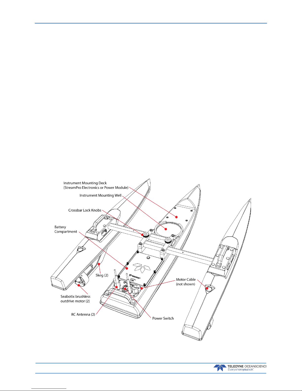
Terminology
Q/Z-1250 systems are comprised of the following components:
Tri-Hull boat
• Made of ABS plastic, the Q/Z-1250 is strong and robust to cope with the worst deployment conditions.
All required cabling, batteries, and antennae are included for easy plug-and-play operation. Electronics are located below deck in a watertight compartment. Doppler profilers of 6.5” (165 mm) diameter
or less may be used with adaptor mounts.
• Two 24 VDC Teledyne Seabotix brushless outdrive motors.
Hitec Aurora 9 Remote-Control System
• Hand held remote transmitter with LCD display for adjusting control settings.
• Paired transmitter receiver receives steering and motor control commands from the transmitter and
sends battery voltage telemetry data back to the transmitter.
• Throttle and steering response characteristics may be adjusted using EPA menu.
Antennae
• Two RC system antennas connected to the receiver to provide redundant operation.
• Optional power/telemetry module includes an additional 2.4GHz, 5dBi antenna for Bluetooth com-
munication.
Figure 1. Q/Z-1250 Overview

Q/Z-1250 Power Trimaran User’s Guide P/N 95L-8001-00 (September 2017)
EAR-Controlled Technology Subject to Restrictions Contained on the Cover Page.
Page 5
Specifications and Operational Limits
Typical Cruising Speed1 1-1.5 m/s (3.3-5.0 fps)
Top Speed1 2.3 m/sec (7.5 ft/sec)
Hull Length 127 cm (50")
Width (extended) 94 cm (37")
Width (transport) 64 cm (25")
Height (no instrument) 32 cm (12.5")
Weight (no instrument) 18 kg (40 lbs)
Weight (typical instrument) 22 kg (48 lbs)
Battery Endurance1 1.0 m/s: ~4 hours 1.5 m/s: >1 hour
Payload (typical) 4.5 kg (10 lbs)
Power 3 @ 24 V, 4.5 AH NiMH Battery Packs
1 @14 V, 4.5 AH NiMH Battery Pack with optional Power Module
Motor 2 x Brushless DC Thrusters
Hull Material ABS (Acrylonitrile Butadiene Styrene)
Hardware Anodized Aluminum, Stainless Steel
R/C Control Hitec
R/C Control Modes 3: Left Throttle/Right Steer; Right Throttle/Left Steer; Dual Throttle
R/C Antenna Omni Directional
R/C Range 750 m
R/C RF Scheme FHSS
R/C Frequency 2.4 GHz
ADCP Size Up to 16.5 cm (6.5") Diameter
Warranty One year on all Q-Boat 1250 components.
1 Speed measured over water; speed over ground will depend on water velocity

P/N 95L-8001-00 (September 2017) Q/Z-1250 Power Trimaran User’s Guide
Page 6
EAR-Controlled Technology Subject to Restrictions Contained on the Cover Page.
Quick Review
Check that you know the
Terminology used
Reference Figure 1. Q/Z-
1250 Overview

Q/Z-1250 Power Trimaran User’s Guide P/N 95L-8001-00 (September 2017)
EAR-Controlled Technology Subject to Restrictions Contained on the Cover Page.
Page 7
System Setup
I NSTALLATION INCLUDES THE FOLLOWING STEPS:
Tri-Hull Assembly
ADCP Installation
Battery Installation and Charging
Charging the Transmitter
Antenna Position
Power On Sequence
P/N 95L-8001-00 (September 2017) Q/Z-1250 Power Trimaran User’s Guide
Page 8
EAR-Controlled Technology Subject to Restrictions Contained on the Cover Page.
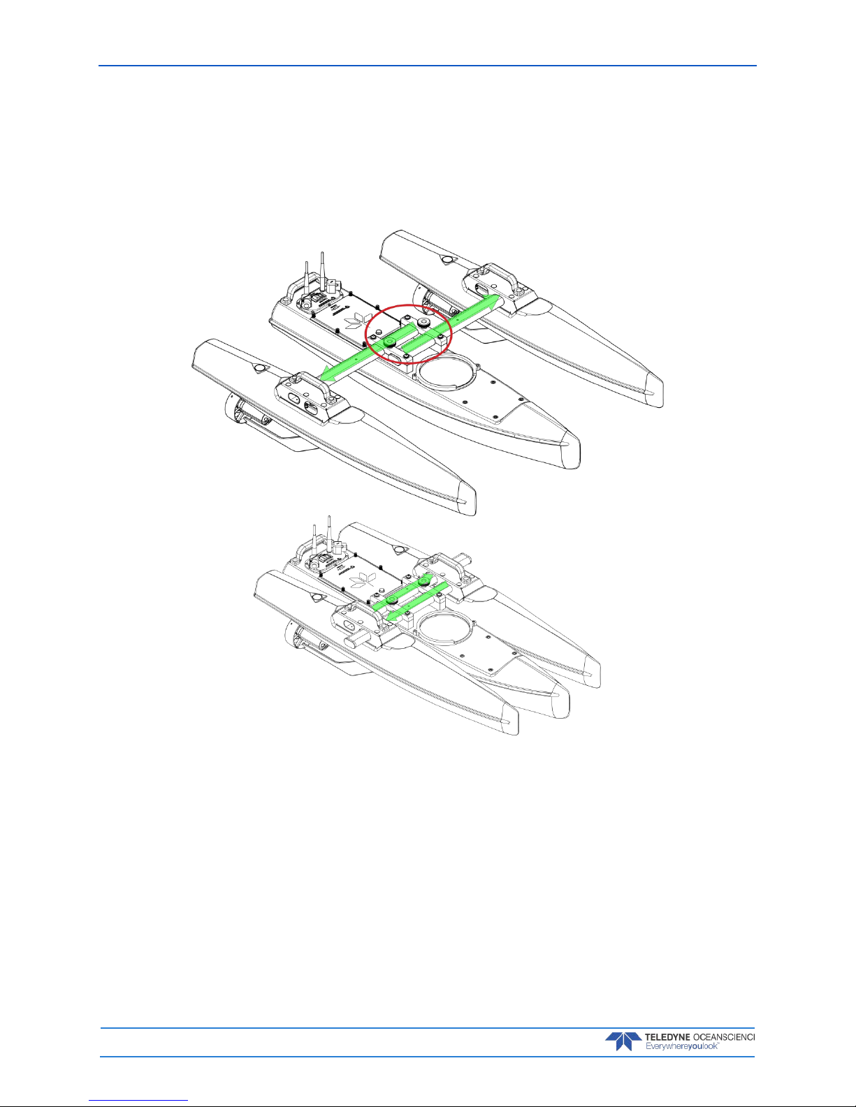
Tri-Hull Assembly
No tools are required to extend the tri-hulls. Simply loosen the locking knobs, extend the tri-hull until it
reaches the stop pin, and then tighten the knobs to lock the crossbars.
To retract the tri-hulls, loosen the locking knobs and push in the tri-hull until it reaches the stop pin, and
then tighten the knobs to lock the crossbars.
Figure 2. Tri-Hull Assembly

Q/Z-1250 Power Trimaran User’s Guide P/N 95L-8001-00 (September 2017)
EAR-Controlled Technology Subject to Restrictions Contained on the Cover Page.
Page 9
ADCP Installation
Although a variety of instruments and sensors can be configured on and into the Q/Z-1250, the most common varieties are shown here.
StreamPro Installation
To install the StreamPro:
1. Loosely attach the Collet 81L-6090-00 to the Instrument Mount 81L-6089-00 using the three M4
screws and flat washers.
2. Install the StreamPro Transducer into the Instrument Mount matching the slots and grooves on
the transducer and mount, inserting the cable connector up through the Collet end of the Instrument Mount assembly. The transdu cer will protrude from the instrument mount as shown in Figure 4.
3. Tighten the Collet 81L-6090-00 using the three M4 screws and flat washers to secure the transducer to the Instrument Mount.
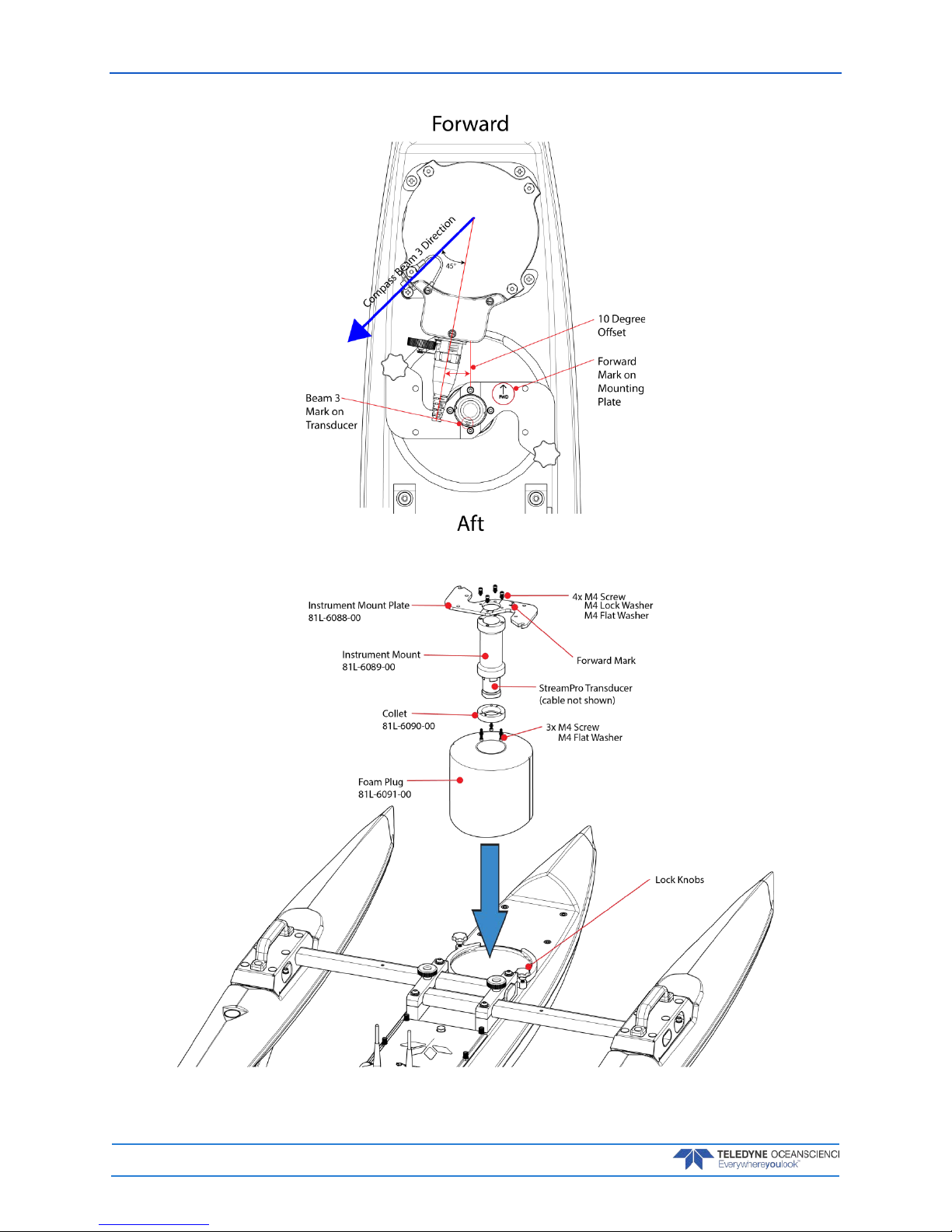
4. Attach the transducer assembly to the Instrument Mounting Plate 81L-6088-00 using the four
M4 screws, flat washers, and lock washers. Note the Forward mark on the Instrument Mounting
Plate and the Beam 3 mark on the transducer do NOT match.
The Instrument Mounting Plate allows the transducer assembly to be mounted in two
orientations, 180 degrees apart. The transducer assembly MUST match the direction of the
electronics chassis compass Beam 3 direction (see Figure 3).
5. Insert the transducer assembly into the StreamPro Foam Plug 81L-6091-00 as shown. Note the
flat side of the foam insert is facing up, and the position of the two notches in the foam ensures
that the curved side of the foam aligns with the hull curvature.
6. Insert the StreamPro instrument assembly into the Q/Z-1250 instrument well and secure it with
the two lock knobs. Note the Forward mark on the Instrument Mounting Plate and the Beam 3
mark on the transducer do NOT match. The StreamPro transducer should protrude slightly below
the Q/Z-1250 hull when installed.
Make sure the arrow on the Instrument Mounting Plate is pointing to the FRONT of the Q/Z1250 and the StreamPro transducer Beam 3 mark is pointed AFT as shown in Figure 3. This
will ensure that the transducer is at a 45-degrees angle (plus the 10 degree offset) and
matches the compass which is located inside the electronics chassis.
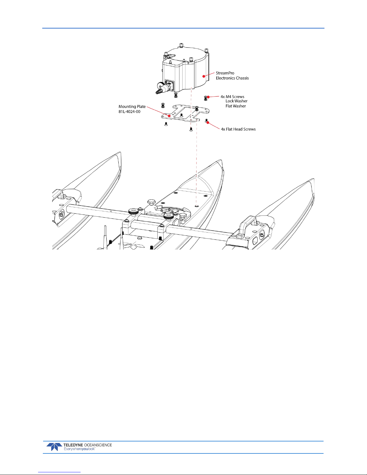
7. Install the Electronic Chassis Mounting Plate 81L-4024-00 to the bottom of the Electronic Chassis using the four flat head screws. Then install the Electronic Chassis onto the Q/Z-1250 main
hull using the four M4 screws, lock washers, and flat washers (see Figure 5).
8. Connect the transducer cable to the electronics chassis.
P/N 95L-8001-00 (September 2017) Q/Z-1250 Power Trimaran User’s Guide
Page 10
EAR-Controlled Technology Subject to Restrictions Contained on the Cover Page.
Figure 3. StreamPro ADCP Installation Overview
Figure 4. StreamPro Transducer Installation
Q/Z-1250 Power Trimaran User’s Guide P/N 95L-8001-00 (September 2017)
EAR-Controlled Technology Subject to Restrictions Contained on the Cover Page.
Page 11
Figure 5. StreamPro Electronics Chassis Installation
SonTek River Surveyor S5 or M9 Installation
To install the Surveyor S5 or M9:
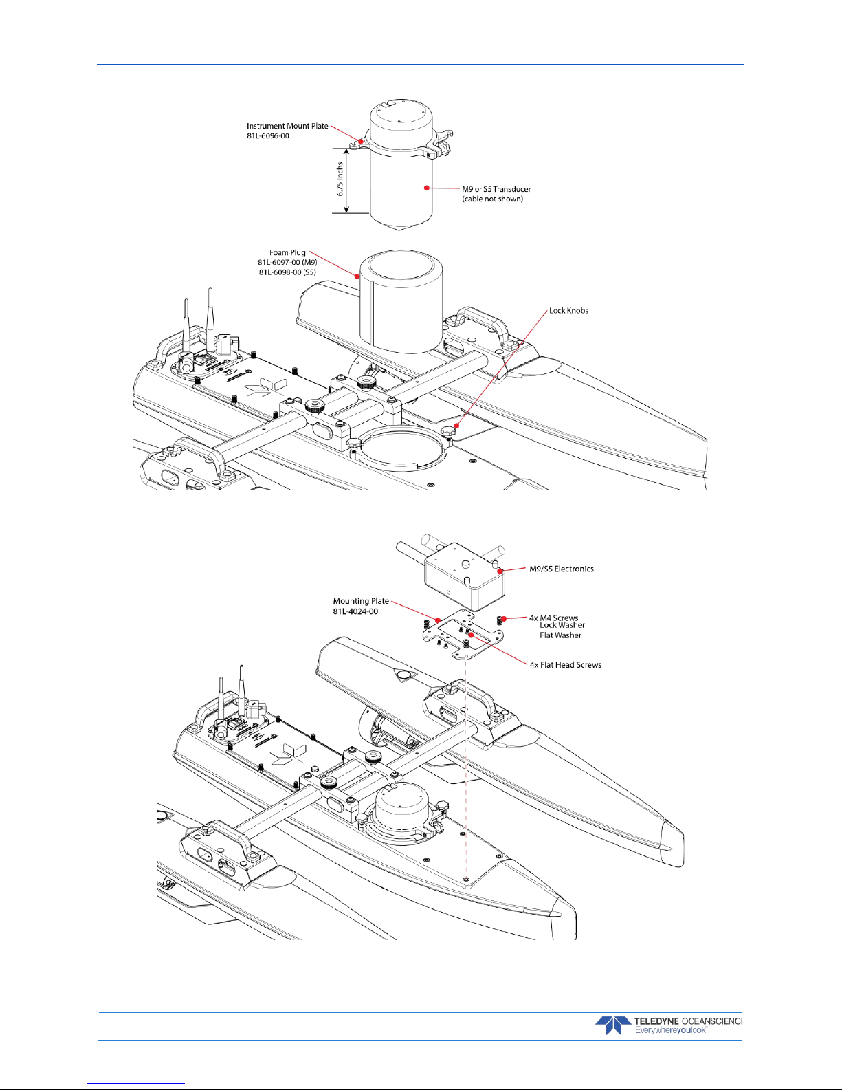
1. Slide the Instrument Mounting Plate 81L-6096-00 around the S5 / M9 as shown (see Figure 6).
2. Place the S5 / M9 in the mounting plate so that it protrudes 6 ¾ inches from the bottom of the
plate as shown. Tighten the knob to hold the mounting plate in place. Do not over tighten the
knob.
3. Use foam plug 81L-6097-00 for M9 transducers and 81L-6098-00 for S5 transducers. Place the
foam plug around the instrument as shown. Note the flat side is facing up and the position of the
two notches in the foam.
4. Install the instrument with the foam plug into the instrument well as shown and secure it with the
two lock knobs.
5. Install the Electronic Chassis Mounting Plate 81L-4024-00 to the bottom of the Electronic using
the four flat head screws. Then install the Electronic Chassis onto the Q/Z-1250 main hull using
the four M4 screws, lock washers, and flat washers (see Figure 7).
6. Connect the transducer cable to the electronics.
P/N 95L-8001-00 (September 2017) Q/Z-1250 Power Trimaran User’s Guide
Page 12
EAR-Controlled Technology Subject to Restrictions Contained on the Cover Page.
Figure 6. SonTek River Surveyor S5 or M9 Transducer Installation
Figure 7. SonTek River Surveyor S5 or M9 Electronics Installation
Q/Z-1250 Power Trimaran User’s Guide P/N 95L-8001-00 (September 2017)
EAR-Controlled Technology Subject to Restrictions Contained on the Cover Page.
Page 13
RiverPro ADCP Installation
To install the RiverPro:
1. Slide the Instrument Mounting Plate around the RiverPro as shown (see Figure 8).
2. Tighten the knob to hold the mounting plate in place. Do not over tighten the knob.
3. Place the foam plug around the RiverPro. Note the flat side is facing up and the position of the two
notches in the foam.
4. Install the instrument with the foam plug into the instrument well and secure it with the two lock
knobs.
5. Install the Power Module using the four M4 screws, lock washers, and flat washers.
6. Connect the RiverPro transducer cable to the Power Module.
Figure 8. RiverPro Installation
P/N 95L-8001-00 (September 2017) Q/Z-1250 Power Trimaran User’s Guide
Page 14
EAR-Controlled Technology Subject to Restrictions Contained on the Cover Page.
Single Beam Echo Sounder Installation
A Single Beam Echo Sounder can be used when installed with the optional Power/Telemetry module. To
install the Single Beam Echo Sounder:
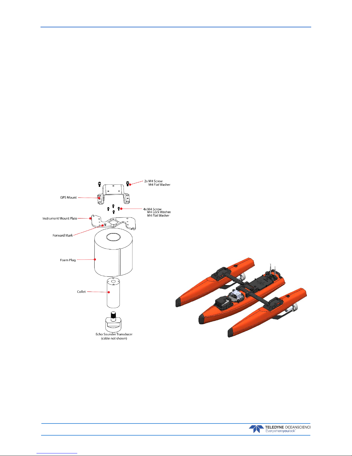
1. Install the Echo Sounder Transducer into the collet, inserting the cable connector up through the
Collet end of the Instrument Mount assembly.
2. Attach the transducer assembly to the Instrument Mount Plate using the four M4 screws, flat
washers, and lock washers. Note the Forward mark on the Instrument Mounting Plate and the
Beam 3 mark on the transducer do NOT match.
3. Insert the transducer assembly into the Foam Plug. Note the flat side of the foam insert is facing
up, and the position of the two notches in the foam ensures that the curved side of the foam aligns
with the hull curvature.
4. Insert the Echo Sounder assembly into the Q/Z-1250 instrument well and secure it with the two
lock knobs.
5. Install the GPS Mount to the Instrument Mount Plate using the two M4 screws and flat washers.
6. Install the Power/Telemetry Module using the four M4 screws, lock washers, and flat washers.
7. Connect the Echo Sounder transducer cable to the Power/Telemetry Module.
Figure 9. Echo Sounder Installation
Q/Z-1250 Power Trimaran User’s Guide P/N 95L-8001-00 (September 2017)
EAR-Controlled Technology Subject to Restrictions Contained on the Cover Page.
Page 15
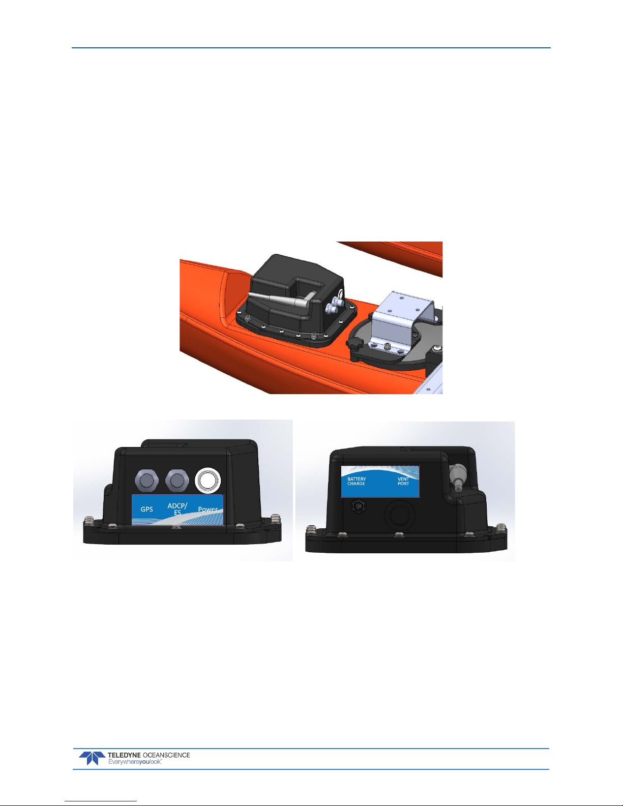
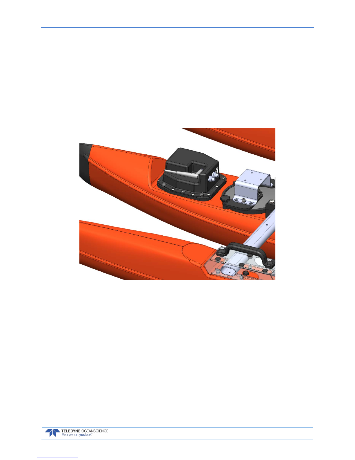
Installing the Power/Telemetry Module
To install the Power/Telemetry Module:
1. Place the Power/Telemetry Module on the Instrument Mounting Deck with the power switch facing Aft.
2. Install the Power/Telemetry Module onto the Q/Z-1250 main hull using the four M4 screws, lock
washers, and flat washers.
3. Connect the ADCP or Single Beam Echo Sounder cable to the Power/Telemetry Module’s Instrument Port.
4. Connect the GPS Cable to the Power/Telemetry Module’s GPS Port.
5. Rotate the antenna to a vertical position.
Figure 10. Power/Telemetry Module Installation
GPS Installation
To install the GPS mounting post and bracket:
1. Use M6 screws and washers to attach the Acrylic GPS mounting bracket to the Instrument Mounting plate.
2. Use the #10-32 screws, washers, and lock nuts to attach the threaded GPS mounting post to the
Acrylic bracket.
3. Screw the GPS receiver onto the GPS mounting post.
4. Connect the GPS cable to the GPS receiver and to the Power/Telemetry module.

P/N 95L-8001-00 (September 2017) Q/Z-1250 Power Trimaran User’s Guide
Page 16
EAR-Controlled Technology Subject to Restrictions Contained on the Cover Page.
Battery Installation and Charging
The Q/Z-1250 uses three 24 VDC, 4.5 AH battery packs connected to the electronics by red / black “Anderson” connectors. Battery life is highly dependent on boat and water speed. This set of 3 battery packs
should last for approximately four hours at 2 kts (1 m/sec), at least 1.5 hours at 3 kts, and approximately
40 minutes at 4 kts (combined boat and water speed).
It is recommended that three battery packs are used in the Q/Z-1250 at all times to ensure
adequate power reserves are available. This also provides security in case one or more packs
are defective / poorly charged.
The batteries are installed in the battery compartment with the thermistor connector and wiring routed
safely out of the way; make sure ALL THREE connectors are accessible. Care must be taken when connecting the batteries. Ensure that the connectors are clean and the “Anderson” terminals are properly interlocked. Periodically inspect the metal terminals inside the connectors. It is good practice to measure
the 3x individual battery cell voltages before and after the survey to ensure all cells are discharging to a
similar voltage which indicates a good status. The Hitec transmitter may be used as a voltmeter to measure individual battery voltage before and after surveys by connecting one battery at a time and noting the
displayed voltage on the LCD panel. Ensure that no battery wiring is trapped between the battery compartment and cover, and then tighten the six battery cover thumbscrews uniformly to create a watertight
seal. Periodically check the O-ring in the battery compartment cover and replace if damaged.
Charging the Batteries
The Q/Z-1250 is normally equipped with three 24V 10Ah NiMH battery packs and a smaller battery pack
inside the handheld RC transmitter. It is important that the user fully charge each battery system before
deployment.
The propulsion batteries’ operating endurance between charges ranges from 30 minutes to four hours,
depending on operating speed and use of steering.
Once each month, the propulsion battery(s) should be fully discharged before recharging to avoid memory
problems that may be caused by repeatedly charging partially discharged batteries.
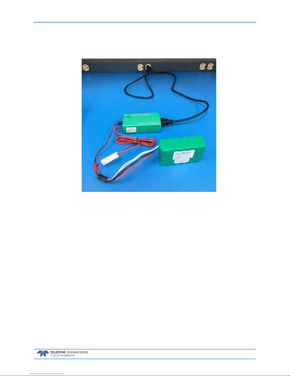
To charge the batteries:
1. Disconnect all shipboard connections to the batteries and remove the batteries from the boat.
2. Place the batteries in a well-ventilated area away from flammable hazards ensuring the batteries
are spaced sufficiently to allow proper airflow during charging.
3. Connect the small red thermistor connector on the battery to the opposite red thermistor connection on the charger.
4. Connect the battery connector to the opposite connector on the charger. Insure that polarities are
correct (black-black, red-red). Plug each 24V smart charger into an acceptable wall unit; the
charger’s LED will flash red a couple of times then shift to solid red. NOTE: if the charger is
plugged into a wall outlet prior to connecting the battery, it may not switch into a charging state
automatically and the LED may remain green. If that occurs, unplug the charger from the wall until the green LED fades off, and then plug it back into the wall.
5. When charging is complete the LED will change to illuminate green.
6. Do NOT overcharge the batteries. Batteries should be supervised while charging and should not
be left unattended. Ensure the batteries are disconnected as soon as charging is complete.
7. Under rare circumstances, the charger may finish the charging cycle prematurely before the battery has been fully charged. Verify that the battery has been fully charged by measuring the voltages across each of the 3 discharge terminals. All voltages should be roughly equal and should be
higher than the battery’s rated voltage of 24V. Also, factor in the duration of charge when deciding
Q/Z-1250 Power Trimaran User’s Guide P/N 95L-8001-00 (September 2017)
EAR-Controlled Technology Subject to Restrictions Contained on the Cover Page.
Page 17
whether to trust the battery charger’s automatic cutoff. Battery packs which are completely discharged should require 3-4 hours to reach a full charge. If you suspect that the charging cycle may
have terminated prematurely, disconnect the battery charger from its AC supply, wait for the LED
to turn off completely, then reconnect the battery charger and restart the charge process.
Figure 11. Charging the Batteries
Battery Charging Recommendations
Battery Use:
• Inspect the battery packs for damage regularly. Do not use damaged or distorted battery packs.
• Make sure the battery polarity is always connected correctly (Red to Red, Black to Black)
• Ensure that all battery connectors are secure and push/pull clips are tight.
• ALWAYS use THREE batteries in the Q/Z-1250. Do not operate on only two batteries. Doing so can
cause premature failure and/or damage to the batteries.
• Never allow water to get inside of the battery pack or Power Module. If there is any evidence of corro-
sion, do not use the battery pack.
• There is no need to remove the battery from the Power Module housing to charge the battery.
• Battery packs will self-discharge when not in use. For best endurance, recharge all battery packs be-
fore use if more than a few days have passed since they were last charged.
Battery Charg ing:
• Always charge in a ventilated area on a work bench away from flammable materials. Do not charge the
batteries inside of the boat.
• Do not leave batteries on charge overnight. Charge when they can be monitored periodically.
• Do not overcharge batteries. Limit charge times to a maximum of 10 hours.

P/N 95L-8001-00 (September 2017) Q/Z-1250 Power Trimaran User’s Guide
Page 18
EAR-Controlled Technology Subject to Restrictions Contained on the Cover Page.
• If the resting 24V battery pack voltage measures less than 16V, do not charge it. The battery pack is no
longer usable and should be disposed of properly.
• Under rare circumstances, the charger may finish the charging cycle prematurely before the battery
has been fully charged. Verify that the battery has been fully charged by measuring the voltages across
each of the 3 discharge terminals. All voltages should be roughly equal and should be higher than the
battery’s rated voltage of 24V. Also, factor in the duration of charge when deciding whether to trust
the battery charger’s automatic cutoff. Battery packs which are completely discharged should require
3-4 hours to reach a full charge. If you suspect that the charging cycle may have terminated prematurely, disconnect the battery charger from its AC supply, wait for the LED to turn off completely,
then reconnect the battery charger and restart the charge process.
• Once each month, the propulsion battery(s) should be fully discharged before recharging to avoid
memory problems that may be caused by repeatedly charging partially discharged batteries.
Battery Charg ing S eq u e nce :
• Connect the Anderson power leads between battery pack and charger.
• Plug the charger into an AC power supply. The red LED will blink on/off a couple of times then stay
on showing that it is charging.
• After battery is fully charged the green LED will be on showing that the battery is fully charged. The
battery should now be disconnected.
• The LED will stay green if there is no battery connected; the charger is functioning properly.
Q/Z-1250 Power Trimaran User’s Guide P/N 95L-8001-00 (September 2017)
EAR-Controlled Technology Subject to Restrictions Contained on the Cover Page.
Page 19
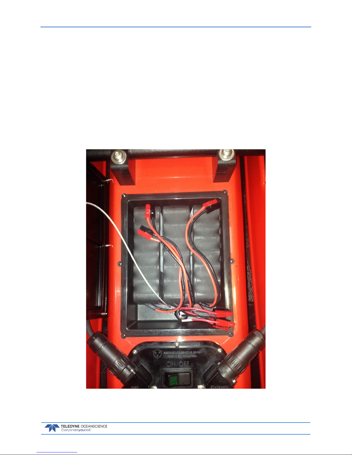
Installing the Battery System
To install the batteries:
1. Remove the battery compartment cover. Note there is a lanyard attached to the battery cover and
the O-Ring on the battery cover. Do NOT place the cover where it is in contact with dirt.
2. Load the three NiMH battery packs in the Q/Z-1250 hull with the leads facing toward the electronics box.
3. Connect all three power leads to the electronics box as shown. Insure polarity is correct (red to
red, black to black).
4. Inspect the battery cover O-Ring. Verify it is clean and no dirt is present. Clean the O-Ring mating
surface on the battery compartment with a lint free wipe.
5. Install the battery compartment cover and evenly tighten all six screws. Make sure the lanyard
and battery leads are not pinched by the cover when installed.
Figure 12. Installing the Batteries

P/N 95L-8001-00 (September 2017) Q/Z-1250 Power Trimaran User’s Guide
Page 20
EAR-Controlled Technology Subject to Restrictions Contained on the Cover Page.
Charging the Transmitter Battery
The Hitec Aurora 9 remote control transmitter is powered by a 6 cell 7.2V NiMH battery with a 110-220V
charger. The charger is simply plugged into the rear of the transmitter, marked Charge as shown below.
The charger should not be connected to the battery continuously for more than 24 hours. The charging
procedure is complete in 12 hours and the charger should be disconnected once the battery is fully
charged.
Be careful not to plug the battery into the transmitter with reverse polarity. The connector is
keyed to prevent this, but if forced onto the unit, it will be destroyed!
DO NOT turn the transmitter power on or attempt to use the transmitter while charging.
Serious damage may occur rendering the unit inoperable.
Figure 13. Charging the Hitec Aurora 9 Remote Control Battery
The LCD display shows the battery charge in volts or percentage of full charge. The screen may be pressed
to toggle between the two choices (see below 100% or 8.0V).
1. Tap on %
2. Display changes to volts

Q/Z-1250 Power Trimaran User’s Guide P/N 95L-8001-00 (September 2017)
EAR-Controlled Technology Subject to Restrictions Contained on the Cover Page.
Page 21
Charging the Power/Telemetry Module
The optional Power/Telemetry module is powered by an internal 14V, 4.5Ah NiMH battery.
To charge the system:
6. Disconnect all instrumentation from the module and remove the module from the boat.
7. Place the module in a well-ventilated area away from flammable hazards. There is no need to remove the battery from the module.
8. Connect the provided smart charger and charging cables (73L-4004-00 and 73L-4005-00) to the
Charge port on the module.
9. Plug the smart charger into an acceptable wall unit; the charger’s LED will flash red a couple of
times then shift to solid red. NOTE: if the charger is plugged into a wall outlet prior to connecting
the battery, it may not switch into a charging state automatically and the LED may remain green.
If that occurs, unplug the charger from the wall until the green LED fades off, then plug it back
into the wall.
10. When charging is complete the LED will change to illuminate green.
11. Do NOT overcharge the module. As with any battery, the module should be supervised while
charging and should not be left unattended. Ensure the module is disconnected as soon as charging is complete.
Figure 14. Charging the Power/Telemetry Module

P/N 95L-8001-00 (September 2017) Q/Z-1250 Power Trimaran User’s Guide
Page 22
EAR-Controlled Technology Subject to Restrictions Contained on the Cover Page.
Antenna Safety
Antenna problems are the most likely cause of Q/Z-1250 control issues or poor data transmission range. It
is critical to ALWAYS check the antenna bulkhead connections before deployment. Ensure the antenna
pins are properly interfaced with the bulkhead connector and check that the antenna cables are connected
and tightly fastened. It is not good enough that the antenna is screwed in – the center pin needs to make a
good connection between the antenna and the cable / bulkhead. ALWAYS make sure the external antennae are tightly installed –they could vibrate loose while the boat is in action.
Check all antenna connections before deployment.
Range Testing
Before each deployment, it is good practice to conduct a range test, where the boat is kept stationary and
the operator moves away to check that good control of the boat navigation is maintained as the distance
increases. Select a control position so the user can move closer to the boat in an emergency. For example,
do not set up at the shoreline where the operator cannot move closer to the boat if a control issue arises.
Setting up the RC controller 50 feet back from the bank affords the operator 50 feet of “reserve” range.
Always conduct a range test before deployment.
Antenna Position
The two antennae aft of the battery compartment are for the remote control system. The black stub antennae should be positioned at a 90-degree angle to maximize signal strength. Both antennae should NOT be
pointed vertically upwards. The worst orientation is both antennae flat and horizontal; this should
ALWAYS be avoided. Teledyne Oceanscience recommends the following antenna orientation:
Figure 15. Antenna Position
Position one antenna UP and one antenna rotated 90 DEGREES outboard to maximize the
signal strength with the RC transmitter antenna (see Figure 16).
If using the optional Power/Telemetry module, its antenna should be oriented vertically.

Q/Z-1250 Power Trimaran User’s Guide P/N 95L-8001-00 (September 2017)
EAR-Controlled Technology Subject to Restrictions Contained on the Cover Page.
Page 23
Elevation
The data telemetry and remote-control range achieved will be GREATLY increased as the operator position is elevated. Elevation is the single biggest factor in achieving effective range. It is advisable to select a
control position where there is maximum elevation, even if this means the operator will be further from
the boat. Both the RC and data antennae are close to the water surface and an elevated control position
greatly enhances the ability of the boat to send / receive data.
Elevation is critical in determining operating range.
The orientation of the RC transmitter antenna becomes important during long range operation. The
transmitter antenna must not be pointed at the boat but instead should remain vertical – in the same direction (plane) as the boat antennae receiving the signal.
Figure 16. Omni Antenna
The antenna is Omni directional (the best reception is around the antenna in a doughnut
shape); do not orientate the antenna by pointing the tip of the antenna at the boat.

P/N 95L-8001-00 (September 2017) Q/Z-1250 Power Trimaran User’s Guide
Page 24
EAR-Controlled Technology Subject to Restrictions Contained on the Cover Page.
Powering Up the Boat and Transmitter
The transmitter should be fully charged before each survey and will operate for several hours when
charged up to 100% indicated on the LCD screen. The transmitter will shut down when the LCD display
indicates 0% battery life remaining. Please see Charging the Remote Transmitter for further details.
Always turn the transmitter power on first and then turn the Q/Z-1250 power on second. Do
not turn the Q/Z-1250 boat power on before the transmitter.
Q/Z-1250When the Q/Z-1250 is turned on, it looks for a RC signal, and if the transmitter is on then it immediately locks to the transmitter signal. The transmitter will beep three times and the propulsion battery
voltage will be shown on the LCD display. If the transmitter is not on when power is applied, the boat may
be affected by stray radio signals. This is dangerous as it can potentially damage the motors on the boat or
create an unsafe operating condition such as motors operating unexpectedly.
Make sure the throttle is at zero before turning on the transmitter. The transmitter will issue
an alarm if the boat is turned on with the throttles open. This promotes safe operation.
The transmitter will beep three times when the boat is powered up and the boat voltage
display will appear on the LCD panel. If this does not happen, there is no radio link
established. Do not launch the boat! Always perform checks that the transmitter is properly
controlling the throttles and steering before launching the boat.
The optional Power/Telemetry Module has its own power switch. Once the Q/Z-1250 power is on, press
the power switch on the Power/Telemetry Module to apply power to the connected Instrument and/or
GPS.

Q/Z-1250 Power Trimaran User’s Guide P/N 95L-8001-00 (September 2017)
EAR-Controlled Technology Subject to Restrictions Contained on the Cover Page.
Page 25
Quick Review
Extend the tri-hulls Reference Tri-Hull Assembly
Install the ADCP Reference ADCP Installation
Charge the batteries and
install in boat
Reference Battery
Installation and Charging
Charge the transmitter
battery
Reference Charging the
Transmitter Battery
Charge the optional
Power/Telemetry module
Reference Charging the
Power/Telemetry Module
Follow the proper power
up sequence
Reference Powering Up the
Boat and Transmitter.

P/N 95L-8001-00 (September 2017) Q/Z-1250 Power Trimaran User’s Guide
Page 26
EAR-Controlled Technology Subject to Restrictions Contained on the Cover Page.
Operation
O PERATION INCLUDES THE FOLLOWING STEPS:
Battery Voltage Monitoring
Failsafe Mode Selection
Using the Remote Control
Using the Optional Power/Telemetry Module
Q/Z-1250 Power Trimaran User’s Guide P/N 95L-8001-00 (September 2017)
EAR-Controlled Technology Subject to Restrictions Contained on the Cover Page.
Page 27
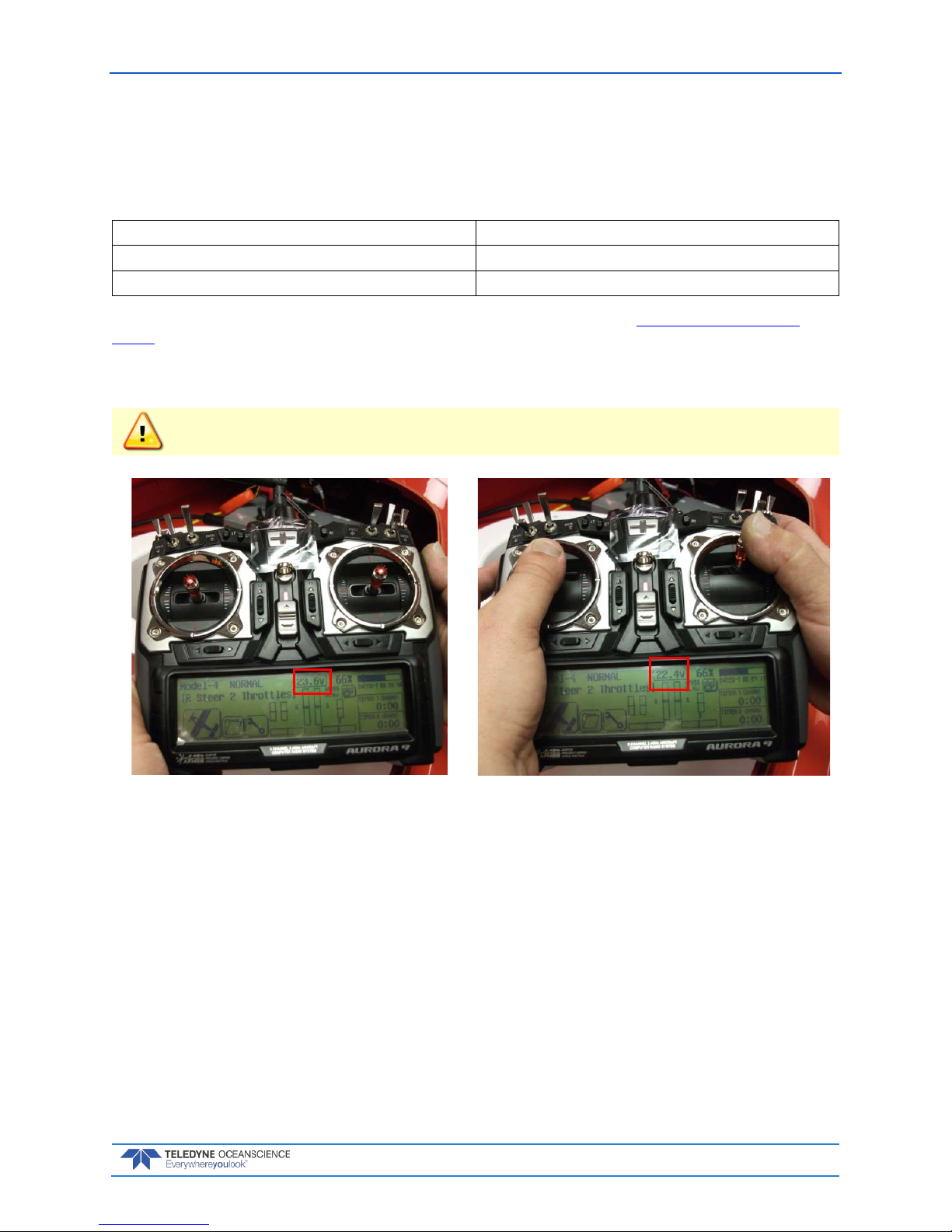
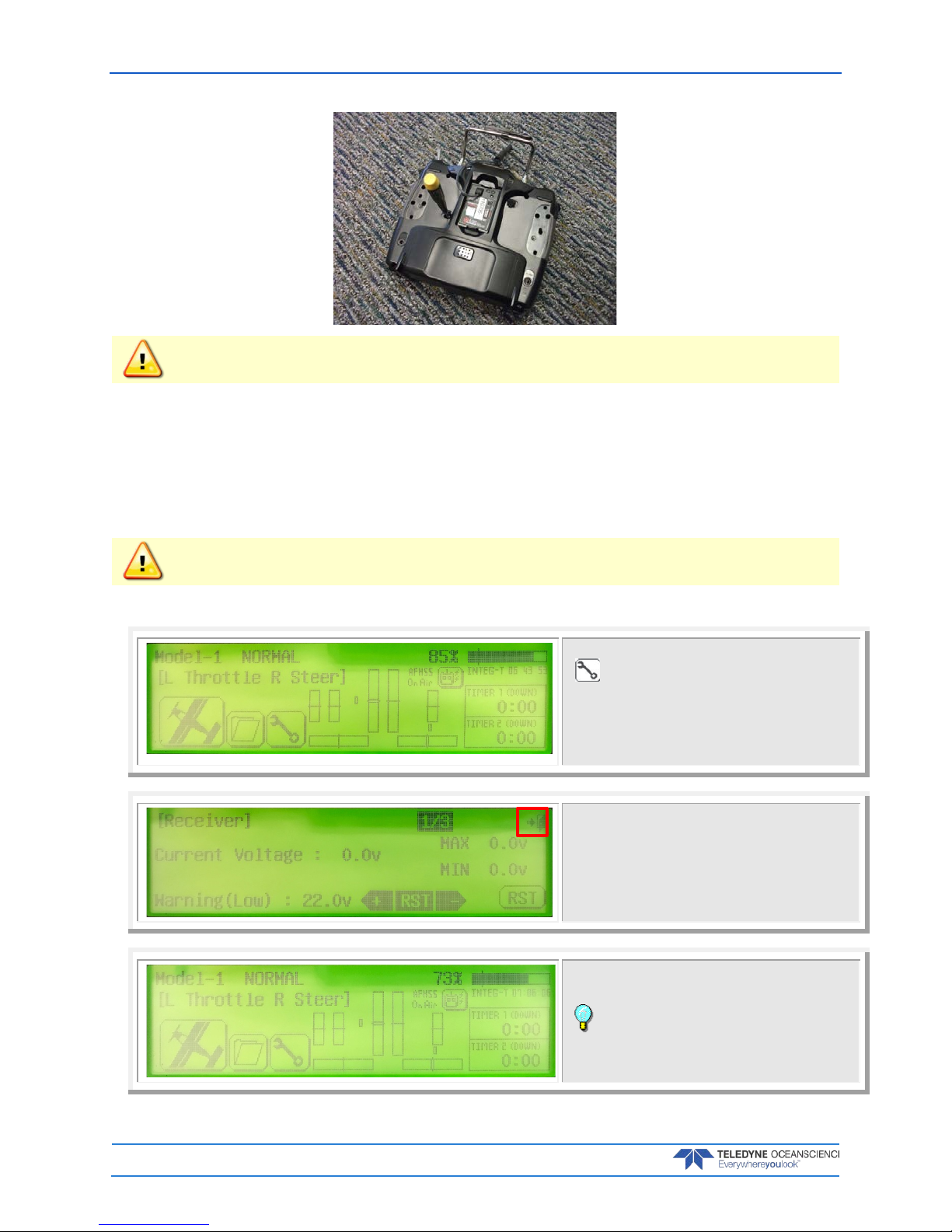
Battery Voltage Monitoring
The Hitec transmitter continuously monitors the Q/Z-1250 battery voltage; an alarm will sound when the
voltage becomes too low signaling that the boat should be brought back to shore. If the voltage falls below
a threshold value as shown below, control of the boat will no longer be possible.
Starting Voltage 26 – 27V
Default alarm set point 22V
Completely dead batteries 18V
The battery alarm voltage setting can be changed by the user if required (see Setting the Low Voltage
Alarm). The alarm set point can be lowered if it is safe to do so. Note that the voltage will drop as soon as
the throttle is opened and power is applied to the motors; this is normal. As the current to the motors increases with speed, the voltage goes down slightly; this may trigger the alarm. The top speed of the boat
will also decrease as the battery voltage decreases.
If the low voltage alarm sounds prematurely you must recover the Q/Z-1250 immediately as
one or more of the battery packs or cells may not be properly connected.
Battery voltage at rest Battery voltage with motors at full power
Figure 17. Monitoring the Q/Z-1250 Battery Voltage
Failsafe Mode Selection
Should the remote control signal be lost, the boat is pre-programmed to enter an emergency “failsafe”
mode. This might happen under the following circumstances:
• The transmitter batteries fail.
• The boat goes behind a structure or large boat and is out of radio contact.
• The boat is too far away and goes out of control range.
• The transmitter is turned off.
Always check the transmitter battery power before starting work.

P/N 95L-8001-00 (September 2017) Q/Z-1250 Power Trimaran User’s Guide
Page 28
EAR-Controlled Technology Subject to Restrictions Contained on the Cover Page.
Always check the failsafe by turning the transmitter “off” after powering up the Q/Z-1250 to make sure
the failsafe works as expected.
Always perform a range test. With the boat on land, walk away from the boat and ensure that the controls still work at a distance further than you plan to control the boat on water.
The factory failsafe settings are as follows:
Port Motor: 0% Throttle
Starboard Motor: 0% Throttle
This failsafe setting protects the operator if the controller is shut off prior to the boat power, and will
cause the boat to drift downstream with the current in river discharge measurement applications. Teledyne recommends an operating position that is downstream of the measurement location whenever possible. In special circumstances, other failsafe settings may be more suitable and we recommend contacting
Teledyne Oceanscience for help changing the failsafe setting if this is desired.
Using the RC Transmitter
End Point Adjustment (EPA)
The Q/Z-1250 transmitter may be programmed via the LCD panel to alter the boat performance characteristics in several useful ways, including:
• Adjusting the speed at maximum throttle to give easier control of survey speed.
• The boat can be made to go more slowly when the throttle is held in the full forward position if the
speed is adjusted downwards from the factory default of 75% (maximum effective setting).
• See Setting Throttle End Points (Restricting Boat Speed).
EPA Performance Notes
• The maximum speed of the Q/Z-1250 is approximately 2.3 m/sec with fully charged batteries, meas-
ured relative to the water (NOT the bottom). Speed over ground will depend on water velocity as well
as throttle setting in river applications.
• Endurance of the Q/Z-1250 will decrease significantly with increasing throttle position and speed over
water.
• At maximum throttle, steering input will decrease the boat speed since one motor must be retarded in
order to turn.
• Speed at maximum throttle will reduce as the battery discharges due to the decrease in effective bat-
tery voltage.
Steering and Throttle Models
The Q/Z-1250 may be operated with several different transmitter stick setups, allowing people who are
left or right handed to be equally comfortable. The Q/Z-1250 has no rudder, thus it always uses differential thrust steering. Q/Z-1250See Throttle and Steering Control Models for further information.
Control Stick Characteristics
The throttle and steering sticks can be operated with either a spring loaded self-centering action or a
ratchet (not self-centering). Adjusting the throttle ratchet may be useful: changing the throttle to ratchet
operation will keep the boat at the same speed without the operator having to touch the throttle stick. See
Changing the Control Stick Characteristics for further information.

Q/Z-1250 Power Trimaran User’s Guide P/N 95L-8001-00 (September 2017)
EAR-Controlled Technology Subject to Restrictions Contained on the Cover Page.
Page 29
Selecting Throttle and Steering Control Models
The transmitter has three different control models used to operate the Q/Z-1250, as follows:
Table 1. Throttle and Steering Control Models
Mode Left Stick Right Stick
MODEL 1 Throttle (both motors) Steering
MODEL 2 Steering Throttle (both motors)
MODLE 3 Port motor throttle Starboard motor throttle
It is up to the user to determine which of the control models is most suitable. Model 1 or 2 is preferable for
beginners to gain experience handling the boat and is most often used. For experienced users, model 3
may be preferred, and is useful in low velocity conditions. Throttle control for all models uses forward/backward stick motion, and steering control for models 1 & 2 uses left/right stick motion. Steering
control for model 3 is obtained by differential throttle positions on the left and right sticks.
The model is selected by pressing on the LCD display. The factory setting is model 1. To change this to any
of the other models, follow the instructions below:
Tap the control model that is currently set.
Tap the new control model from the list.
Tap Select.
Tap Yes to switch models.

P/N 95L-8001-00 (September 2017) Q/Z-1250 Power Trimaran User’s Guide
Page 30
EAR-Controlled Technology Subject to Restrictions Contained on the Cover Page.
The selected model displays on main screen.
Setting Throttle End Points (Restricting Boat Speed)
The maximum throttle power can be adjusted on the transmitter to reduce the Q/Z-1250 top speed with
the stick(s) in the fully forward position. This allows for a fine control of boat speed and easier control of
the boat in slow or still water.
It is recommended that the throttle response is adjusted using the End Point Adjustment (EPA) before
commencing a survey. If the Q/Z-1250 is operated at maximum speed, battery life is adversely affected
and the total survey line distance that can be covered on each battery charge may be significantly less than
at a lower speed that will be more "fuel efficient".
Endurance is reduced significantly when operated at high speed.
Q/Z-1250For river discharge measurement applications the peak water velocity in the river and the river
width will determine the minimum safe top boat speed. The EPA setting should always provide a top
speed at least 20 to 30% higher than the river’s peak water velocity to avoid control issues and ensure that
the boat is not washed downstream by the flow in the river, since the top boat speed will be reduced when
the operator is applying steering input. An EPA setting of 75% ensures that the boat’s maximum speed capability is always available. An EPA setting of 55% will provide a top speed of approximately 1.5 m/sec,
while an EPA setting of 40% will provide a top speed of approximately 1.0 m/sec. EPA setting below 40%
are not recommended.
IMPORTANT: The EPA is set for each individual control model. For example, if model 1 operation (right stick steering, left stick throttle) is selected, the end points shown on the LCD panel only ap-
ply to model 1. To change the end points for the other control models, select each model in turn and
then follow the end point adjustment procedure for each mode.
How to set END POINTS:
Select the system menu signified by the wrench image.
Select the EPA Menu.
Q/Z-1250 Power Trimaran User’s Guide P/N 95L-8001-00 (September 2017)
EAR-Controlled Technology Subject to Restrictions Contained on the Cover Page.
Page 31
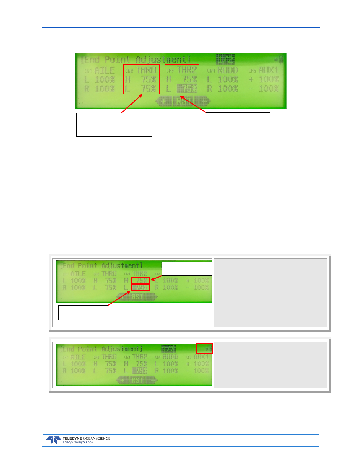
The EPA menu shows the two motors’ throttle settings for that control mode (see picture below).
• + is forward direction
• - is reverse direction
• The Q/Z-1250 utilizes the channels 2 and 3 settings.
• Channels 2 and 3 are the starboard and port throttles, respectively.
• The maximum available setting is always 140% but the maximum useful setting is 75%; this will give
maximum boat speed in water. Higher settings will simply reduce the effective stick control range.
• Do not set the reverse direction above 75%.
• The port and starboard throttle channels should always have the same EPA settings, otherwise the
boat will have a strong tendency to turn in circles due to unbalanced thrust from the two motors.
• The lower the percent setting, the slower the boat will go.
• Test the settings thoroughly before deploying the boat.
Adjust the EPA settings by pressing on the channel to
be adjusted. The forwards and backwards (+ and -)
directions are selected by moving the throttle stick(s)
forward and back.
The percent setting is increased or decreased by
pressing on the “+” or “-“ arrows at the bottom of the
LCD display.
To make the boat slower, press “-“,
To make the boat faster, press “+”.
Pressing RST resets the throttles to 100%.
To EXIT from any menu on the display, press the BACK
key.
Follow the pictures and examples below on how to select the Right/Left motor channels:
Forward direction (+)
Reverse direction (-)
Starboard Throttle – Channel 2
Port Throttles – Channel 3

P/N 95L-8001-00 (September 2017) Q/Z-1250 Power Trimaran User’s Guide
Page 32
EAR-Controlled Technology Subject to Restrictions Contained on the Cover Page.
Select right motor channel.
Right motor channel is highlighted.
Right (Starboard) motor throttle = Channel 2
Press stick back for reverse direction.
Release the stick.
Select the left motor channel.
Left motor highlighted
Left (Port) motor throttle = Channel 3

Q/Z-1250 Power Trimaran User’s Guide P/N 95L-8001-00 (September 2017)
EAR-Controlled Technology Subject to Restrictions Contained on the Cover Page.
Page 33
EXAMPLE: Reduce maximum throttle on right motor from 75% to 50%:
Select right motor channel.
Right motor is highlighted.
Right (Starboard) motor throttle = Channel 2
Press stick forward for forward direction.
While holding the stick forward, tap the minus arrow
to reduce the maximum speed to 50%.
The settings can be changed back to the factory 75% /
75% by this procedure, using the “+” arrow button to
increase the maximum speed.

P/N 95L-8001-00 (September 2017) Q/Z-1250 Power Trimaran User’s Guide
Page 34
EAR-Controlled Technology Subject to Restrictions Contained on the Cover Page.
Changing the Control Stick Characteristics
The Q/Z-1250 transmitter is set up from the factory with “self-centering” throttle controls. When the
throttle stick is released, a spring causes it to go back to the zero center position immediately. This helps
to provide safe operation of the boat, especially for inexperienced users.
The springs that cause the “self-centering” can be deactivated, and then a ratchet activated on the throttle
sticks to allow the sticks to remain at the set throttle position even without being held there by the operator. This is sometimes preferred when using the Q/Z-1250 in “dual throttle” mode (Mode 3). It is also very
useful when conducting long surveys as the throttle stick can be left in position to maintain a constant
speed.
To change the spring and ratchet settings, four small screws can be accessed through the rear of the transmitter, as shown below. The following adjustments are possible:
• M1/3 – Right throttle spring off (clockwise), spring on (anti-clockwise).
• M2/4 – Left throttle spring off (clockwise), spring on (anti-clockwise)
A – Right throttle ratchet off (anti-clockwise), ratchet on (clockwise). Two screws are under the protective
cover - use screw on right.
B - Left throttle ratchet off (anti-clockwise), ratchet on (clockwise). Two screws are under the protective
cover – use screw on left.
Screw A / B positions with protective covers removed:
1. The spring for the left (port) motor throttle can be turned off by turning the M2/4 screw anticlockwise.
M1/3
M2/4
A B A
B

Q/Z-1250 Power Trimaran User’s Guide P/N 95L-8001-00 (September 2017)
EAR-Controlled Technology Subject to Restrictions Contained on the Cover Page.
Page 35
2. The ratchet for the left (port) throttle can be activated by turning screw B clockwise until the
ratchet sound is heard when moving the stick.
3. The spring for the right (starboard) motor throttle can be turned off by turning the M1/3 screw
anti-clockwise.
4. The ratchet for the right (starboard) throttle can be activated by turning screw A clockwise until
the ratchet sound is heard when moving the stick.
P/N 95L-8001-00 (September 2017) Q/Z-1250 Power Trimaran User’s Guide
Page 36
EAR-Controlled Technology Subject to Restrictions Contained on the Cover Page.
Do not loosen any screw more than four or five turns as it may come loose. The spring
activation / deactivation requires only one turn.
Setting the Low Voltage Alarm
IMPORTANT: The voltage alarm is set for each individual control mode. For example, if mode 1
operation (left stick throttle, right stick steering) is selected, the battery low voltage alarm shown on the
LCD panel only applies to mode 1. To change the low voltage alarm for the other control modes, select
each mode in turn and then follow the battery voltage alarm setting procedure for each mode.
If any of the control modes have the low voltage alarm “off”, then switching to this control
mode will disable the alarm.
To set the Low Voltage Alarm:
On the main menu, tap the Wrench icon
( ).
Tap System tab Sensor Battery.
At Warning(Low), press the plus sign (+) or minus sign
(–) until the value reads:
22.0v for Q/Z-1250.
Tap the Back icon several times until you reach the
main menu.
Repeat setting the low voltage alarm for all models.
Return to the desired Model after the low voltage
alarm setting is applied to all models.
Q/Z-1250 Power Trimaran User’s Guide P/N 95L-8001-00 (September 2017)
EAR-Controlled Technology Subject to Restrictions Contained on the Cover Page.
Page 37
Using the Power/Telemetry Module
The Q/Z-1250 may be configured with an optional Power/Telemetry module to enable use of externally
powered sensors and sensors that require external radio data transmission.
Overview
The Power/Telemetry module is a self-contained unit with battery and Bluetooth radio inside. A shore
Bluetooth radio is required for telemetry and may be provided with the system depending on the configuration. The module has two data ports, a battery charging port, an antenna connector, and a power button. See Instrument Installation for details on configuration-specific connections.
Figure 18. Power/Telemetry Module Overview
Setup
The Power/Telemetry module should be fully charged before use. See Charging the Power/Telemetry
Module. The Q/Z-1250 Power/Telemetry module is recommended to be used with the SD1000U USB
Bluetooth adapter. Other Bluetooth radios may be used with the module if desired.
All instruments connected to the Power/Telemetry Module (RiverRay, RiverPro, Single Beam Echo
Sounder, or GPS) should be configured to output data with Baud rate 115,200.
With all instrument connections made (see Instrument Installation), depress the power button to turn on
the module. The power button will glow blue when the module is powered on. The module will now provide power to connected instrumentation and its internal Bluetooth radio will be active. If the module has
already been paired to a SD1000U which is also powered on, their connection will re-establish automatically. If a new SD1000U or one with Mode set to 0 is used, it can be connected to the Q/Z-1250
Power/Telemetry module now.

P/N 95L-8001-00 (September 2017) Q/Z-1250 Power Trimaran User’s Guide
Page 38
EAR-Controlled Technology Subject to Restrictions Contained on the Cover Page.
Operation
Always test the data telemetry function before beginning a survey.
With all instrument connections made (see Instrument Installation), depress the power button to turn on
the module. The power button will glow blue when the module is powered on. The module will now provide power to connected instrumentation and its internal Bluetooth radio will be active.
Connect the paired SD1000U to the laptop. It should automatically connect to the Power/Telemetry
module and the SD1000U “Connect” LED will blink to indicate the successful connection. The SD1000U
“RS232” LED should blink to indicate receipt of data.
The SD1000U com port can now be opened in a terminal program or other software to receive the data
from the Power/Telemetry module at Baud rate 115,200. See SD1000U Com Port Identification.
Using the SD1000U USB Bluetooth Adapter
The SD1000U USB Bluetooth device is recommended for use with the Q/Z-1250 Power/Telemetry module and is included with some systems depending on configuration. The SD1000U appears as a com port
to a laptop.
If your SD1000U device was not included as a configured part of a Q/Z-1250 system, see Pairing the
SD1000U for configuration steps.
• This information was created using the SD1000U on a Windows 7® laptop.
• For compatibility with the Q/Z-1250 Power/Telemetry module, set all baud rates to 115200Kb.
In Windows XP® and later systems the driver may load automatically when you plug in the
SD1000U adapter. TRDI strongly recommends that users install the drivers and test
communications in a location with internet access, before proceeding to their measurement
location.
SD1000U Baud Rate Setting
Refer to the Sena documentation and the diagram on the device for switch settings or use the table below.
The switches are shown with the adapter held in your hand with the USB connector to the left and the antenna to the right. For the DIP switches, ON = Right; OFF = Left. The switches on the dongle determine
the baud rate between the dongle and the laptop. All devices connected to the Q/Z-1250 Power/Telemetry
module including the SD1000U should have a Baud rate setting of 115200.
TRDI has observed latency issues while collecting data using a Bluetooth adapter other than
the SD1000U. The user must take suitable precautions.
All devices connected to the Q/Z-1250 Power/Telemetry module including the SD1000U
should have a Baud rate setting of 115200.
Table 2. SD1000U DIP Switch Setting
Baud
Rate
2400 4800 9600 19.2K 38.4K 57.6K 115.2K S/W
ON
OFF
OFF
OFF
ON
OFF
ON
ON
ON
OFF
ON
ON
ON
OFF
ON
OFF
OFF
ON
ON
ON
OFF
OFF
OFF
OFF
Hardware Flow Control Handshaking
No Use Use
OFF ON

Q/Z-1250 Power Trimaran User’s Guide P/N 95L-8001-00 (September 2017)
EAR-Controlled Technology Subject to Restrictions Contained on the Cover Page.
Page 39
Figure 19. SD1000U Dip Switches
SD1000U Com Port Identification
Plug in the SD1000U device to a USB port and use Windows Device Manager® to determine the Com
port as shown in the snap shot for a Windows 7
®
laptop. In this case Com 16.
If you have many ports as shown above and are not sure of which port is the Parani one,
remove the adapter, wait a moment, note the list of ports, reinsert the adapter and note
the new (Parani) port.
Pairing the SD1000U USB Bluetooth Adapter
If a new SD1000U or one set to Mode 0 is used, it should be paired to the Q/Z-1250 Power/Telemetry
module prior to operation. Use the Parani software to manage the device.

P/N 95L-8001-00 (September 2017) Q/Z-1250 Power Trimaran User’s Guide
Page 40
EAR-Controlled Technology Subject to Restrictions Contained on the Cover Page.
ParaniWin Software Configuration
To install and configure ParaniWin:
1. Load the ParaniWin® software from the CD onto your computer.
2. Double click on Software.
3. Double click on setup_ParaniWin-v1.04.exe.
4. When the software is installed on your laptop, the desktop icon will look as shown below.

Q/Z-1250 Power Trimaran User’s Guide P/N 95L-8001-00 (September 2017)
EAR-Controlled Technology Subject to Restrictions Contained on the Cover Page.
Page 41
5. Run the ParaniWin program. It looks as follows:
6. The baud rate should be 115200. See SD1000U Baud Rate Setting.
7. Enter the COM port identified in SD1000U Com Port Identification.
8. The first time you use the dongle you will need to use Mode 0. Subsequently you can chose to use
Mode 1.
Select Mode 1 if you want the adapter to automatically connect to the last device connected each
time you plug the adapter into your computer, and automatically reconnect if the connection is
lost. This is the recommended mode for operation of the Q/Z-1250 Power/Telemetry module.
You can always drop the existing connection and connect to a different device using the
ParaniWin software even when using Mode 1. Chose Mode 0 if you do not want the adapter to
automatically connect and reconnect to an ADCP.

P/N 95L-8001-00 (September 2017) Q/Z-1250 Power Trimaran User’s Guide
Page 42
EAR-Controlled Technology Subject to Restrictions Contained on the Cover Page.
Some Bluetooth devices may ask for a Passkey, PIN code, Pair code, Pairing code, Security
code, or Bluetooth code.
In all cases, the code is 0 or 0000 (zero, not the letter o).
The pin code is 0 for systems shipped prior to August 2017 and 0000 for systems shipped
after August 2017.
9. Click Apply. You will receive a Completed Configuration message.
10. Click Connection (out).
11. Click the Search button.
12. This example shows a RiverRay system. The Q/Z-1250 Power/Telemetry Module will display a
device name of “QZ1250SN____” with the serial number of the Power/Telemetry module. Click
Connect. You will receive a “Connected successfully” message.
13.
Exit the ParaniWin program by clicking on the X.
14. The SD1000U com port can now be opened in a terminal program or other software to receive the
data from the Power/Telemetry module.

Q/Z-1250 Power Trimaran User’s Guide P/N 95L-8001-00 (September 2017)
EAR-Controlled Technology Subject to Restrictions Contained on the Cover Page.
Page 43
Quick Review
Select a Throttle and
Steering Control Mode
Reference Selecting Throttle
and Steering Control Modes
Set the maximum throttle
speed
Reference Setting Throttle
End Points (Restricting Boat
Speed)
Set the Low Voltage
Alarm
Reference Setting the Low
Voltage Alarm

P/N 95L-8001-00 (September 2017) Q/Z-1250 Power Trimaran User’s Guide
Page 44
EAR-Controlled Technology Subject to Restrictions Contained on the Cover Page.
Maintenance
M AINTENANCE INCLUDES THE FOLLOWING STEPS:
After Each Use Maintenance
Checking the Thruster Oil Compensation
O-Ring Replacement

Q/Z-1250 Power Trimaran User’s Guide P/N 95L-8001-00 (September 2017)
EAR-Controlled Technology Subject to Restrictions Contained on the Cover Page.
Page 45
General Maintenance
After Each Use
The Q/Z-1250 is designed to be easy to maintain.
• To prolong the life of the hull and finish, wash with mild soap and water after each use. Use a hose
with a low velocity spray nozzle to rinse the top and bottom. The system can be stood on its end to facilitate rinsing the underside.
• If operating in saltwater, rinse the hull and motors with fresh water after each use. Place the system in
a container of fresh water and run the thrusters for a period of about two minutes at low speed to
rinse any salt, mud or other contaminants from the exterior of the system. Utilization of this method
ensures the best clean possible.
• When possible, allow the system to air dry prior to stowing in the transit case. Low pressure air and
clean dry towels can be substituted to speed the drying process.
• Check the battery compartment cover O-Ring for cuts, cracks or deformation. This O-Ring seals the
battery area from water intrusion and should be checked frequently.
After Each Use (Dirty Water Conditions)
When the system is operated in dirty water environments with high sediment loads or significant biological activity or the presence of drifting debris, the cleaning process will need to be more involved.
First visually inspect the propeller guards for fouling. Any material sticking out from under the propeller
requires the removal of the propeller to remove the fouling. With material under the hub of the propeller,
the potential for the material to be ingested into the shaft seals of the propeller is increased.
To remove the propeller:
1. Disconnect and remove the batteries from the boat.
2. Remove the two each 6 mm radio pattern nuts, and pull the propeller off of the collet.
3. Remove any debris from underneath the propeller hub and re-install.

P/N 95L-8001-00 (September 2017) Q/Z-1250 Power Trimaran User’s Guide
Page 46
EAR-Controlled Technology Subject to Restrictions Contained on the Cover Page.
Checking the Thruster Oil Compensation
After every 50 hours of operational use, we recommend checking the fill level on the oil compensation
bladders for each thruster. This procedure should also be performed if the system has been stored for six
months or more.
To check the oil compensation bladder:
1. Place the boat bottom side up on a flat stable surface.
2. Locate the oil compensation bladder on each thruster, visually verify that the bladder is filled and
not flat or distended. Check for small to medium sized air bubbles in the oil compensation tube.
3. If required, add oil from the Oil Compensation Top Off Kit following the instructions provided
with the kit.
4. Connect and test the thrusters.
Filling the Oil Compensation Tube
To fill the oil compensation tube:
Kit Includes:
• LU003 – 250 ml – KLEAROL® mineral oil
• SS081 – 1 ea - 10cc syringe
• SS176 – 1 ea - Needle-taper 22G a
• DOCS-025 Manufacturer Safety Data Sheets (MSDS), Mineral Oil - 1443952
Tools required, but not provided in the Oil Compensation Top Off Kit:
• #2 Phillips screwdriver
• Diagonal cutters
Optional:
• Paper towels
• Isopropyl alcohol, (for oil spill cleanup)
Read the entire procedure prior to performing any work outlined in this manual. If any
questions remain, please contact Seabotix service department at 619-450-4000 Ext 124 or email service@seabotix.com or contact your local distributor. A complete listing of Teledyne
SeaBotix Inc. distributors can be found on our web site www.seabotix.com.
Read and follow all safety instructions contained in the Manufacturers Safety Data Sheet
(MSDS) (DOCS-025) provided with your Oil Compensation Top Off Kit. It contains important
information regarding the safe handling of the oil provided.
Teledyne recommends that latex or rubber gloves be worn during the oil handling portions of
this procedure.
Q/Z-1250 Power Trimaran User’s Guide P/N 95L-8001-00 (September 2017)
EAR-Controlled Technology Subject to Restrictions Contained on the Cover Page.
Page 47
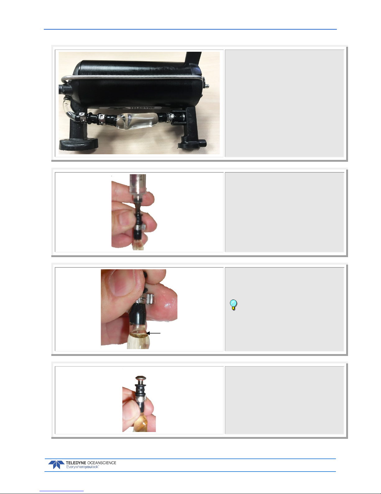
Set up a clean work area. Cover the work
surface with a paper towel to absorb any
spilled oil.
Stand the thruster up in a Kort nozzle.
Remove the oil compensation tube from
the two clips holding the tube in place.
Remove the seal screw from the oil com-
pensation bladder. Once the screw has
been removed, you will have to keep the
oil compensation bladder open end
pointed up. Securing it to a vertical surface will ease accomplishment of this
task.
Fill the supplied syringe (SS081 with
SS176 needle taper tip Installed) with
approximately 5cc of mineral oil
(LU003). Then insert the oil filled syringe into the end of the bladder.
Inject the oil into the oil compensation
bladder until the oil is even with the top
of the radius of the compensation bladder.
It may be necessary to slightly twist
the bladder to remove any set taken by
the oil compensation bladder.
Install the seal screw; only inserting 2-3
threads into the plastic end.
Fill Oil to
this level
P/N 95L-8001-00 (September 2017) Q/Z-1250 Power Trimaran User’s Guide
Page 48
EAR-Controlled Technology Subject to Restrictions Contained on the Cover Page.
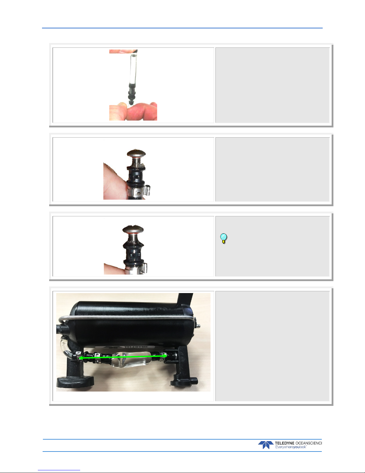
While holding the top of the oil compen-
sation tube, tap the lower section with
your fingers. The goal here is NO AIR.
Continue tapping until all the air bubbles have risen to the top of the oil compensation bladder.
Add more oil if needed to fill the compensation bladder all the way up to the
radius of the oil compensation bladder
section.
Gently squeeze the oil compensation
bladder to remove all of the air.
At first there will be small bubbles that
will form around the base of the screw;
then the oil will start to come out.
Once no more bubbles are coming out
with the oil, tighten the seal screw.
Do not over tighten the seal screw,
as it may damage the threads or the Oring.
Press the oil compensation bladder into
the two clips as shown.

Q/Z-1250 Power Trimaran User’s Guide P/N 95L-8001-00 (September 2017)
EAR-Controlled Technology Subject to Restrictions Contained on the Cover Page.
Page 49
Replacing the O-Ring
The battery compartment O-ring should be cleaned whenever the cover is removed and replaced
BEFORE it is showing any signs of wear and tear.
The O-ring should be replaced every one to two years maximum.
To replace the O-ring:
1. Turn the power switch off.
2. Open the battery compartment by removing all six screws. Note there is a lanyard attached to the
battery cover.
3. Gently pry the O-ring from the groove. Use a wood or plastic wedge to help lift the O-ring from the
groove.
4. Clean the O-ring groove using a lint free cloth. Be sure the groove is free of foreign matter, dirt,
and scratches.
5. Lubricate the O-ring with a thin coat of silicone lubricant. Use as little lubricant as possible; use
just a sufficient amount to change the color of the O-ring.
Apply the lubricant using latex gloves. Do not let loose fibers or lint stick to the O-ring.
Fibers can provide a leakage path.
6. Press the O-ring into the groove on the battery cover.
7. Clean the O-Ring mating surface on the battery compartment with a lint free wipe.
8. Install the battery compartment cover by installing all six screws until fully tightened. Make sure
the lanyard and battery leads are not pinched by the cover when installed.
Figure 20. Replacing the Battery Compartment O-Ring

P/N 95L-8001-00 (September 2017) Q/Z-1250 Power Trimaran User’s Guide
Page 50
EAR-Controlled Technology Subject to Restrictions Contained on the Cover Page.
Replacing a Thruster
To replace a thruster:
1. Turn off the power switch and disconnect the batteries.
2. Disconnect the thruster cable.
3. Remove the skeg by first removing the screw holding the skeg on the Kort nozzle. Then remove
the two M4 screws, and flat washers. Slide the skeg away from the Kort nozzle to free it from the
slot and set it aside (see Figure 21).
4. Remove the four M4 screws and flat washers on the thruster mounting plate. Thread the cable
through the access holes and place the thruster.
5. When installing the new thruster, pass the cable through the hole before installing the four M4
screws and flat washers. Tighten the screws to 10.6 IN-LB.
6. Install the slot on the skeg onto the Kort nozzle and install the screw. Install the two M4 screws
and flat washers. Tighten the two M4 screws to 10.6 IN-LB.
Figure 21. Thruster Installation
Q/Z-1250 Power Trimaran User’s Guide P/N 95L-8001-00 (September 2017)
EAR-Controlled Technology Subject to Restrictions Contained on the Cover Page.
Page 51
Quick Review
Rinse the Q/Z-1250 after a
deployment
Reference General
Maintenance
Check that the battery
compartment O-Ring is in
good condition
Reference Replacing the O-
Ring

P/N 95L-8001-00 (September 2017) Q/Z-1250 Power Trimaran User’s Guide
Page 52
EAR-Controlled Technology Subject to Restrictions Contained on the Cover Page.
NOTES
 Loading...