

Page 1
Operator’s
Manual
PP065/PP066
Transmission Line
Probe
Page 2

Page 3

© 2013 Teledyne LeCroy, Inc. All rights reserved.
Unauthorized duplication of Teledyne LeCroy documentation materials other than for
internal sales and distribution purposes is strictly prohibited. However, clients are
encouraged to distribute and duplicate Teledyne LeCroy documentation for their own
internal educational purposes.
WaveMaster, WavePro, and Teledyne LeCroy are registered trademarks of Teledyne
LeCroy, Inc. Windows is a registered trademark of Microsoft Corporation. Other product
or brand names are trademarks or requested trademarks of their respective holders.
Information in this publication supersedes all earlier versions. Specifications are subject
to change without notice.
Warranty
Teledyne LeCroy warrants this oscilloscope accessory for normal use and operation
within specification for a period of one year from the date of shipment. Spare parts,
replacement parts and repairs are warranted for 90 days.
In exercising its warranty, Teledyne LeCroy, at its option, will either repair or replace any
assembly returned within its warranty period to the Customer Service Department or an
authorized service center. However, this will be done only if the product is determined
by Teledyne LeCroy’s examination to be defective due to workmanship or materials, and
the defect is not caused by misuse, neglect, accident, abnormal conditions of operation,
or damage resulting from attempted repair or modifications by a non-authorized service
facility.
The customer will be responsible for the transportation and insurance charges for the
return of products to the service facility. Teledyne LeCroy will return all products under
warranty with transportation charges prepaid.
This warranty replaces all other warranties, expressed or implied, including but not
limited to any implied warranty of merchantability, fitness or adequacy for any particular
purposes or use. Teledyne LeCroy shall not be liable for any special, incidental, or
consequential damages, whether in contract or otherwise.
922225-00 Rev A
July 2013
Page 4
PP065/PP066 Passive Probe
CAUTION of potential damage to equipment, or WARNING of potential for
bodily injury. Attend to the accompanying information/product manual to
protect against personal injury or damage. Do not proceed until conditions
are fully understood and met.
DOUBLE INSULATION
PROTECTIVE (EARTH) TERMINAL
Safety Instructions
This section contains instructions that must be observed to keep this
oscilloscope accessory operating in a correct and safe condition. You are
required to follow generally accepted safety procedures in addition to the
precautions specified in this section. The overall safety of any system
incorporating this accessory is the responsibility of the assembler of the
system.
Symbols
These terms and symbols may appear on the probe body or in this manual to
alert you to important safety considerations.
Precautions
To avoid personal injury or damage to property, review and comply with the
following safety precautions. Use product only as specified.
Connect only to grounded instruments. Use only with compatible Teledyne
LeCroy oscilloscopes that have their BNC input connected to an earth ground. Do
not connect the probe reference lead to any point which is at a potential other
than earth ground.
Connect and disconnect properly. Connect probe to the oscilloscope before
connecting the probe to the test circuit. Disconnect the probe input and
reference lead from the test circuit before disconnecting the probe from the
oscilloscope.
Do not overload. To avoid electric shock or fire, do not apply any potential to
the probe leads that exceeds the maximum rating of the probe.
2 922225-00 Rev A
Page 5

Operator’s Manual
Observe all terminal ratings. To avoid electric shock or fire, observe all markings
on the oscilloscope before connecting. Consult the respective oscilloscope
product manual for further ratings information.
Do not remove probe casing. Removing the probe’s case or touching exposed
connections may result in electric shock.
Use only within operational environment listed. Do not use in wet or explosive
atmospheres. Keep product surfaces clean and dry.
Use only accessories compatible with the probe.
Handle with care. The probe tip is extremely sharp and may puncture skin or
cause other bodily injury if not handled properly.
Keep fingers behind the finger guard of probe body and accessories.
Do not operate with suspected failures. Before each use, inspect the probe and
accessories for any potential damage such as tears or other defects in the probe
body, cable jacket, accessories, etc. If any part is damaged, cease operation
immediately and sequester the probe from inadvertent use.
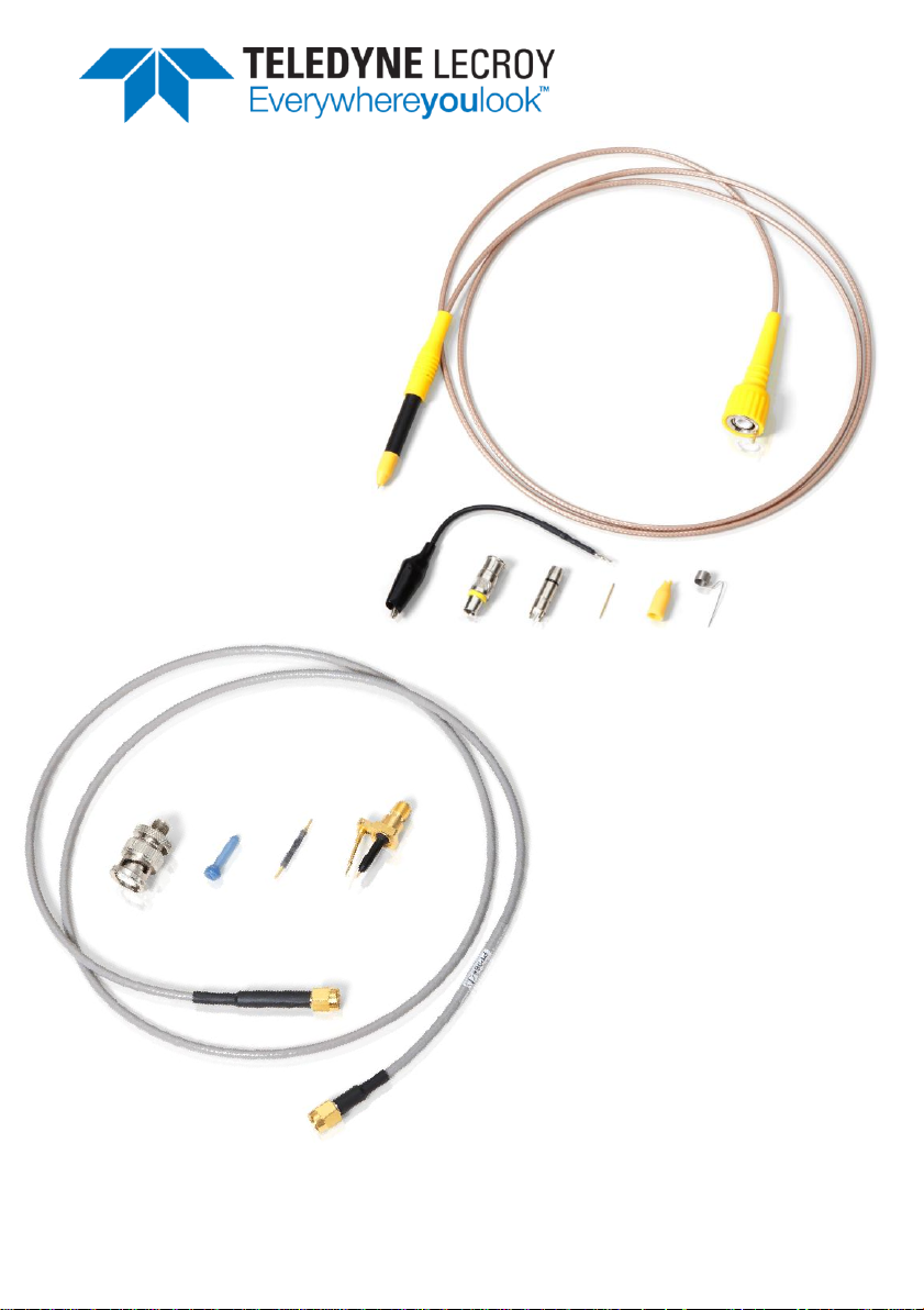
Introduction
The PP066 is a ÷10 high frequency probe using a special 50 Ω cable with an SMA
connector for high-speed transmission line type measurements. Input resistance
is 500 Ω. It is designed to be used with high bandwidth oscilloscopes.
A ÷20 attenuation probe resistor is included to increase the input resistance to 1
kΩ. An SMA-to-BNC adapter has been provided to connect the probe to an
oscilloscope with a BNC input connector for measurements at lower frequencies.
The spring loaded, hinged ground pin contributes to contact stability, in addition
to making it easier to reach into dense circuitry.
The PP065 is a ÷100 probe using a 50 Ω cable with a BNC connector for
transmission line type measurements. Input resistance is 5 kΩ.
NOTE: For proper attenuation and high-speed performance, the PP066 and
PP065 probes must be connected to an oscilloscope having a 50 Ω input.
922225-00 Rev A 3
Page 6

PP065/PP066 Passive Probe
Key Features:
Small size
High bandwidth
Very low input capacitance
Standard Accessories
The PP066 is shipped with the following standard accessories:
÷20 Probe Resistor
SMA-to-BNC Adapter
Plastic Nose Housing
Instruction Manual
The PP065 is shipped with the following standard accessories:
BNC Adapter
PCB Adapter
Ground lead 11cm
Spring tip 0.5mm
Insulating Tip
IC Insulating Tip
Ground lead short on probe tip
For part numbers, refer to Replaceable Parts section.
4 922225-00 Rev A
Page 7

Operator’s Manual
Operation
Handling the Probe
Exercise care when handling and storing the probe. Always handle the probe by
the probe body. Avoid putting excessive strain on the probe cable or bending it
sharply.
Connecting the Probe to the Test Instrument
The PP066 and PP065 probes have been designed for use with Teledyne LeCroy
oscilloscopes.
Connecting the probe to any oscilloscope using the SMA-to-BNC adapter will
make the total of the measuring system equal to the bandwidth of the
oscilloscope.
NOTE: For proper operation, the input of the oscilloscope needs to be set to
50 Ω.
Connecting the Probe to the Test Circuit
To maintain the high-performance capability of the probe, care must be
exercised when connecting the probe to the test circuit. Increasing the parasitic
capacitance or inductance in the input paths may deteriorate the performance
by introducing a "ring" or slowing the rise time of fast signals. To obtain the
highest performance, keep the body of the probe perpendicular to the circuit
under test.
922225-00 Rev A 5
Page 8

PP065/PP066 Passive Probe
Replacing the Attenuating Resistor (PP066)
The attenuation of the PP066 probe can be changed from ÷10 to ÷20 or visa
versa by changing the resistor inside the probe body. To change or replace the
resistor:
1. Remove the nose housing by rotating it counter clockwise and pulling it
away from the probe body taking care not to bend or twist the resistor
inside the housing.
2. Pull resistor straight out of the probe body without twisting or bending
the resistor.
3. Insert a different resistor by gently inserting one end of the resistor into
the probe body.
4. Install the nose housing by carefully sliding it over the resistor and
screwing it onto the probe body.
NOTE : The 450 Ω (÷10) resistor is directional. The dotted end of the resistor
needs to placed towards the probe side. The 950 Ω (÷20) resistor is not
directional. Two different Nose Housings have been supplied to indicate the
probe's attenuation: a black one to indicate a 450 Ω resistor for÷10 attenuation
and a blue one to indicate a 950 Ω resistor for ÷20 attenuation.
Oscilloscope Attenuation Setting
Because the PP066 and PP065 probes are not supplied with ProBus encoding,
you'll have to set the system's attenuation manually by entering the probe
attenuation on the (input) Channel setup dialog.
In addition, when using an oscilloscope capable of different input resistances, set
the resistance to 50 Ω by opening the channel’s vertical setup dialog and
selecting DC50 Ω from the Coupling pop-up selector.
6 922225-00 Rev A
Page 9

Operator’s Manual
Care and Maintenance
Cleaning
The exterior of the probe and cable should only be cleaned using a soft cloth
moistened with water or isopropyl alcohol. The use of abrasive agents, strong
detergents, or other solvents may damage the probe.
CAUTION. The probe case is not sealed and should never be immersed in
any fluid.
Assure that the input receptacles are free of debris before inserting connection
accessories.
Service Strategy
All repair and maintenance should be referred to qualified service personnel.
Defective probes must be returned to a LeCroy service facility for diagnosis and
exchange. A defective probe under warranty will be repaired or replaced with a
factory refurbished probe. A probe that is not under warranty can be exchanged
for a factory refurbished probe. A modest fee is charged for Ihis service. A
defective probe must be returned in order to receive credit for the probe core.
Returning a Probe
Contact your local Teledyne LeCroy service center for calibration or other
service. The service center will give you a Return Material Authorization (RMA)
code and instruct you where to ship the product. All products returned to the
factory must have an RMA.
Return shipments must be prepaid. Teledyne LeCroy cannot accept COD or
Collect shipments. We recommend air-freighting. Insure the item you’re
returning for at least the replacement cost.
1. Remove all accessories from the product. Do not include the manual.
2. Pack the product in its case, surrounded by the original packing material (or
equivalent).
922225-00 Rev A 7
Page 10

PP065/PP066 Passive Probe
3. Label the case with a tag containing:
The RMA
Name and address of the owner
Product model and serial number
Description of failure or requisite service
4. Pack the product case in a cardboard shipping box with adequate padding to
avoid damage in transit.
5. Mark the outside of the box with the shipping address given to you by
Teledyne LeCroy; be sure to add the following:
ATTN: <RMA code assigned by Teledyne LeCroy>
FRAGILE
6. If returning a product to a different country:
Mark the shipment as a "Return of US manufactured goods for
warranty repair/recalibration."
If there is a cost for the service, list the cost in the Value column and
the original purchase price "For insurance purposes only."
Be very specific about the reason for shipment. Duties may have to be
paid on the value of the service.
8 922225-00 Rev A
Page 11

Operator’s Manual
Description
Part Number
QTY.
Probe Body*
PACC-PB001
1
Probe Cable
PACC-CB001
1
÷10 Resistor
PACC-X1001
1
÷20 Resistor
PACC-X2001
1
Plastic Nose Housing, Black
PACC-NH001
1
Plastic Nose Housing, Blue
PACC-NH002
1
SMA-to-BNC Adapter
PACC-AD001
1
Description
Part Number
QTY.
BNC Adapter
PK1-5MM-110
1
PCB Adapter
PK1-5MM-107
1
Ground Lead 11cm
PK1-5MM-102
1
Spring Tip 0.5mm
PK007-005
1
Insulating Tip
PK1-5MM-105
1
IC Insulating Tip
PK1-5MM-108
1
Ground lead short on probe tip
PK1-5MM-118
1
Replaceable Parts
PP066
* Probe body is supplied with a ÷10 resistor and a black plastic nose housing.
PP065
922225-00 Rev A 9
Page 12

PP065/PP066 Passive Probe
PP065
PP066
Nominal Characteristics
(guaranteed by design, but do not have associated tolerances)
Input Dynamic Range
± 15 V
rms
System Attenuation
100:1 ±1%
÷10 and ÷20 ±1% plus 50 Ω
termination tolerance
Input Resistance
5 kΩ ±0.5%
÷10 500 Ω ±1% plus 50 Ω
termination tolerance
÷20 1 kΩ ±1% plus 50 Ω
termination tolerance
Coupling
50 Ω
50 Ω
Maximum non-destruct
input voltage
30 V (DC + peak AC)
Typical Characteristics
(performance not guaranteed, but representative of the average performance from a
sample of several probes)
System Bandwidth (-3 dB)
1 GHz
DC to 7.5 GHz
Rise Time
47 psec
Input Capacitance
2 pF ±5%
0.25 pF
Environmental Characteristics
Operating Temperature
0o to 50o C at 80% RH
0o to 45o C at 80% RH
Humidity
≤ 80% at 31o C max.
≤ 80% at 31o C max.
Altitude
up to 3000 m (9850 ft)
up to 3000 m (9850 ft)
Physical Characteristics
Weight
38 g *
26.5 g (0.94 oz) †
Cable Length
1.4 m
1 m ±20 mm
Specifications
* Probe plus accessories.
† Probe only.
10 922225-00 Rev A
Page 13

Operator’s Manual
Certifications
This section certifies the probe’ Safety and Environmental compliance.
EC Declaration of Conformity - Safety
The probe meets intent of EC Directive 2006/95/EC for Product Safety.
Compliance was demonstrated to the following specifications as listed in the
Official Journal of the European Communities:
EN 61010-031/A1:2008 Safety requirements for electrical equipment for
measurement, control, and laboratory use – Part 031: Safety requirements for
hand-held probe assemblies for electrical measurement and test.
Environmental Compliance
END-OF-LIFE HANDLING
The probe is marked with this symbol to indicate that it complies
with the applicable European Union requirements to Directives
2002/96/EC and 2006/66/EC on Waste Electrical and Electronic
Equipment (WEEE) and Batteries.
The probe is subject to disposal and recycling regulations that vary
by country and region. Many countries prohibit the disposal of
waste electronic equipment in standard waste receptacles. For
more information about proper disposal and recycling of your
Teledyne LeCroy product, please visit teledynelecroy.com/recycle.
RESTRICTION OF HAZARDOUS SUBSTANCES (ROHS)
The probe conforms to 2011/65/EU RoHS2 Directive based on the fact it is
classified as an Industrial Monitoring and Control Instrument (per Article 4,
Paragraph 24), and these products and associated accessories are exempt from
RoHS compliance until 22 July 2017 (per Article 4, Paragraph 3).
922225-00 Rev A 11
Page 14

PP065/PP066 Passive Probe
Teledyne LeCroy Service Centers
United States and Canada -
World Wide Corporate Office
Teledyne LeCroy Corporation
700 Chestnut Ridge Road
Chestnut Ridge, NY, 10977-6499, USA
Ph: 800-553-2769 / 845-425-2000
FAX: 845-578-5985
teledynelecroy.com
Support:
contact.corp@teledynelecroy.com
Sales:
customersupport@teledynelecroy.com
United States - Protocol Solutions Group
Teledyne LeCroy Corporation
3385 Scott Boulevard
Santa Clara, CA, 95054, USA
FAX: 408-727-0800
teledynelecroy.com
Sales and Service:
Ph: 800-909-7211 / 408-727-6600
contact.corp@teledynelecroy.com
Support:
Ph: 800-909-7112 / 408-653-1260
psgsupport@teledynelecroy.com
European Headquarters
Teledyne LeCroy SA
4, Rue Moïse Marcinhes
Case postale 341
1217 Meyrin 1
Geneva, Switzerland
Ph: + 41 22 719 2228 / 2323 /2277
FAX:+41 22 719 2233
contact.sa@teledynelecroy.com
applications.indirect@teledynelecroy.com
teledynelecroy.com/europe
Protocol Analyzers:
Ph: +44 12 765 03971
Singapore, Oscillosocpes
Teledyne LeCroy Singapore Pte Ltd.
Blk 750C Chai Chee Road #02-08
Technopark @ Chai Chee
Singapore 469003
Ph: ++ 65 64424880
FAX: ++ 65 64427811
Singapore, Protocol Analyzers
Genetron Singapore Pte Ltd.
37 Kallang Pudding Road, #08-08
Tong Lee Building Block B
Singapore 349315
Ph: ++ 65 9760-4682
China
Teledyne LeCroy Corporation Beijing
Rm. 2001 - Office; Rm. 2002 - Service Center
Unit A, Horizon Plaza
No. 6, Zhichun Road, Haidian District
Beijing 100088, China
Ph: ++86 10 8280 0318 / 0319 / 0320
FAX:++86 10 8280 0316
Service:
Rm. 2002
Ph: ++86 10 8280 0245
Korea
Teledyne LeCroy Korea
10th fl.Ildong Bldg.
968-5 Daechi-dong, Gangnam-gu
Seoul 135-280, Korea
Ph: ++ 82 2 3452 0400
FAX: ++ 82 2 3452 0490
Taiwan
LeColn Technology Co Ltd.
Far East Century Park, C3, 9F
No. 2, Chien-8th Road,
Chung-Ho Dist., New Taipei City, Taiwan
Ph: ++ 886 2 8226 1366
FAX: ++ 886 2 8226 1368
Japan
Teledyne LeCroy Japan
Hobunsya Funchu Bldg, 3F
3-11-5, Midori-cho, Fuchu-Shi
Tokyo 183-0006, Japan
Ph: ++ 81 4 2402 9400
FAX: ++ 81 4 2402 9586
teledynelecroy.com/japan
Contact Teledyne LeCroy
12 922225-00 Rev A
Page 15

Page 16

 Loading...