

Page 1
PP007-WR-1
PP007-WR-2
PP007-WS-1
PP007-WS-2
Operator’s
Manual
PP007 Passive Probe
Page 2

Page 3

© 2013 Teledyne LeCroy, Inc. All rights reserved.
Unauthorized duplication of Teledyne LeCroy documentation materials other than for
internal sales and distribution purposes is strictly prohibited. However, clients are
encouraged to distribute and duplicate Teledyne LeCroy documentation for their own
internal educational purposes.
WaveSurfer, WaveRunner, and Teledyne LeCroy are registered trademarks of Teledyne
LeCroy, Inc. Windows is a registered trademark of Microsoft Corporation. Other product or
brand names are trademarks or requested trademarks of their respective holders.
Information in this publication supersedes all earlier versions. Specifications are subject to
change without notice.
Warranty
Teledyne Lecroy warrants this oscilloscope accessory for normal use and operation within
specification for a period of one year from the date of shipment. Spare parts, replacement
parts and repairs are warranted for 90 days.
In exercising its warranty, Teledyne Lecroy, at its option, will either repair or replace any
assembly returned within its warranty period to the Customer Service Department or an
authorized service center. However, this will be done only if the product is determined by
Teledyne Lecroy’s examination to be defective due to workmanship or materials, and the
defect is not caused by misuse, neglect, accident, abnormal conditions of operation, or
damage resulting from attempted repair or modifications by a non-authorized service
facility.
The customer will be responsible for the transportation and insurance charges for the return
of products to the service facility. Teledyne Lecroy will return all products under warranty
with transportation charges prepaid.
This warranty replaces all other warranties, expressed or implied, including but not limited
to any implied warranty of merchantability, fitness or adequacy for any particular purposes
or use. Teledyne Lecroy shall not be liable for any special, incidental, or consequential
damages, whether in contract or otherwise.
922207-00 Rev A
January 2013
Page 4
PP007 Passive Probe
High Voltage, risk of electric shock.
CAUTION of potential damage to equipment, or WARNING of potential
for bodily injury. Attend to the accompanying information/product
manual to protect against personal injury or damage. Do not proceed
until conditions are fully understood and met.
DOUBLE INSULATION
PROTECTIVE (EARTH) TERMINAL
Safety Instructions
This section contains instructions that must be observed to keep this
oscilloscope accessory operating in a correct and safe condition. You are
required to follow generally accepted safety procedures in addition to the
precautions specified in this section. The overall safety of any system
incorporating this accessory is the responsibility of the assembler of the
system.
Symbols
These terms and symbols may appear on the probe body or in this manual to
alert you to important safety considerations.
Precautions
To avoid personal injury or damage to property, review and comply with the
following safety precautions. Use product only as specified.
Connect only to grounded instruments. Use only with compatible Teledyne
LeCroy oscilloscopes that have their BNC input connected to an earth ground. Do
not connect the probe reference lead to any point which is at a potential other
than earth ground.
Connect and disconnect properly. Connect probe to the oscilloscope before
connecting the probe to the test circuit. Disconnect the probe input and
reference lead from the test circuit before disconnecting the probe from the
oscilloscope. To avoid injury or death due to electric shock, do not connect or
2 922207-00 Rev A
Page 5

Operator’s Manual
disconnect probes or probe accessories while they are connected to a voltage
source.
Do not overload. To avoid electric shock or fire, do not apply any potential to
the probe leads that exceeds the maximum rating of the probe.
Comply with voltage derating curve. When measuring higher frequency signals,
comply with the Voltage vs. Frequency Derating Curve.
Observe all terminal ratings. To avoid electric shock or fire, observe all markings
on the oscilloscope before connecting. Consult the respective oscilloscope
product manual for further ratings information.
Do not remove probe casing. Removing the probe’s case or touching exposed
connections may result in electric shock.
Use only within operational environment listed. Do not use in wet or explosive
atmospheres. Keep product surfaces clean and dry.
Use only accessories compatible with the probe.
Handle with care. The probe tip is extremely sharp and may puncture skin or
cause other bodily injury if not handled properly.
Keep fingers behind the finger guard of probe body and accessories.
Do not operate with suspected failures. Before each use, inspect the probe and
accessories for any potential damage such as tears or other defects in the probe
body, cable jacket, accessories, etc. If any part is damaged, cease operation
immediately and sequester the probe from inadvertent use.
Operating Environment
The accessory is intended for indoor use and should be operated in a clean, dry
environment. Before using this product, ensure that its operating environment is
maintained within these parameters:
Temperature: Operating, 0° to 50° C; Non-operating, - 40° to 71° C
Humidity: 5% to 85% relative humidity (%RH) up to +30° C
5% to 65% RH above +30° C to 40° C
5% to 45% RH above 40° C
Altitude: Up to 2000 m (6560 ft)
922207-00 Rev A 3
Page 6

PP007 Passive Probe
Introduction
The PP007 is a miniature high impedance passive probe. Its high input resistance
and low capacitance make it ideal from general purpose probing of signals with
frequency content from DC through several hundred MHz. The PP007 has a
large selection of connection accessories, both supplied standard with the probe
and available from Teledyne Lecroy as optional accessories.
The PP007 is available in two models, differing only in the design of the
compensation network.
The PP007-WR is designed for use with Teledyne Lecroy WaveRunner series
oscilloscopes.
The PP007-WS is designed for use with Teledyne Lecroy WaveSurfer series
oscilloscopes.
All standard and optional accessories are interchangeable between all models.
Specifications
Electrical Characteristics
Attenuation 10 1%
Input Resistance 10 M 1%
Input Capacitance 9.5 pF
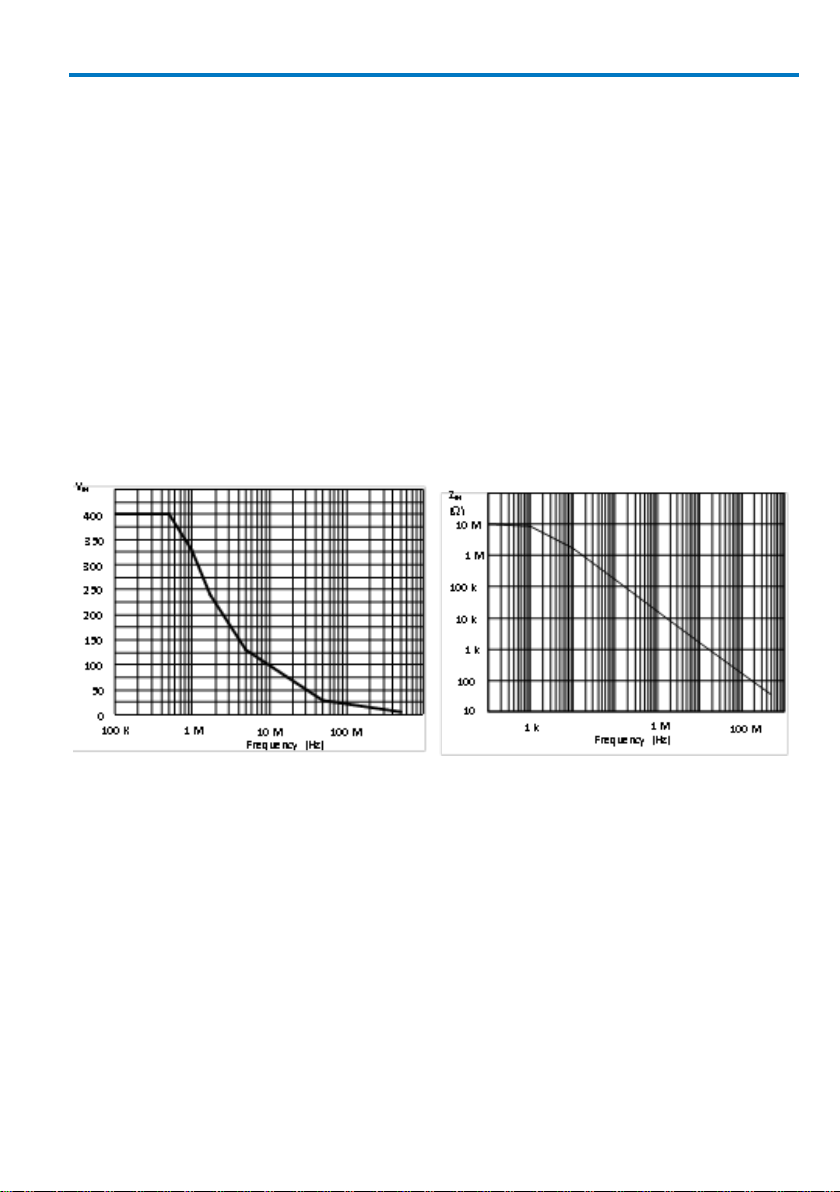
Input Impedance (see plot on page 5.)
Compensation Range 10 – 20 pF
Bandwidth 500 MHz (-3 dB)
Electrical Ratings*
Maximum Input Voltage Measurement category I: 400 V rms,
1250 V transient overvoltage
(see voltage derating curve on next page)
Measurement category II: 300 V rms CAT II
Pollution Degree 2
* See Certifications for an explanation of ratings.
4 922207-00 Rev A
Page 7
Operator’s Manual
Max. VIN versus Frequency,
Measurement Category I
Typical Input Impedance
General Characteristics
Operating Temperature 0o to +50o C
Storage Temperature -40o to +71o C
Altitude, Operating up to 2000 m (6560 ft)
Humidity 5% to 85% relative humidity (%RH) up to +30° C
5% to 65% RH above +30° C to 40° C
5% to 45% RH above 40° C
Cable Length 1.3 m
Weight (probe only) 42 g
922207-00 Rev A 5
Page 8

PP007 Passive Probe
Connectivity Accessories
Teledyne Lecroy provides over 30 individual accessories for the PP007-xx probe,
which enable reliable connections to any physical requirement. In addition to
those provided with the standard probe, several optional varieties are available
either individually, or grouped in sets related to specific applications.
The PK007 series of connectivity accessories are compatible with any Teledyne
Lecroy 2.5 mm PP0x7 series probe.
Accessories are shown with the Teledyne Lecroy part number followed by the
description.
6 922207-00 Rev A
Page 9

Standard Accessories
1
PK007-001
Sprung Hook
2
PK007-002
Standard Ground Lead
3
PK007-003
Adjustment Tool
4, 5
PK007-004 Rigid Tip, 0.5mm
PK007-005 Spring Tip, 0.5 mm
6
PK007-007
Insulating Cap
7, 8, 9, 10, 11
PK007-008 IC Cap, 0.5 mm pitch, (green)
PK007-009 IC Cap, 0.65 mm pitch, (blue)
PK007-010 IC Cap, 0.8 mm pitch, (gray)
PK007-011 IC Cap, 1.0 mm pitch, (brown)
PK007-012 IC Cap, 1.27 mm pitch, (black)
12
PK007-006
Color Coding Rings (set)
13
PK007-013
Ground Blade
14
PK007-016
Ground Spring
(Not shown)
15
PK007-014
Copper Pad
16
PK007-015
PCB Adapter
PP007-OM-E
Instruction Manual
Operator’s Manual
922207-00 Rev A 7
Page 10

PP007 Passive Probe
17
PK007-017
Single Lead Adapter
18
PK007-018
Dual Lead Adapter
19
PK007-022
Adapter, 2 mm plug
20
PK007-023
Adapter, 4 mm plug
21
PK007-019
Pico Hook™
22
PK007-020
Micro Clip, Long
23
PK007-021
Micro Clip, Short
24
PK007-031
BNC Adapter
(For low voltage use only 42 V pk AC + DC)
Optional Accessories
INPUT ADAPTERS AND CLIPS
8 922207-00 Rev A
Page 11

GROUND LEADS
25
PK007-024
Probe Tip Ground Lead w 0.8 mm Socket
26
PK007-025
Probe Tip Ground Lead with Alligator Clip
28
PK007-026
Ground Lead with mini clip
29
PK007-027
Ground Lead with 8 mm
socket
30
PK007-028
Ground Lead with 2 mm plug
31
PK007-029
Ground lead with 4 mm plug
32
PK007-030
High Frequency Compensated Ground Lead
Operator’s Manual
*The PK007-030 High Frequency compenated ground lead allows operation with long ground lead
wiith minimum signal distortion.
922207-00 Rev A 9
Page 12

PP007 Passive Probe
PROBE CONNECTIVITY KITS
The following kits containing an assortment of probe connection accessories can
be ordered directly from Teledyne Lecroy. Refer to the illustrations on pages 5-7
for identification.
PK701 Basic Adapter Kit replaces the common standard accessories, with 2 each
of designators 1, 2, 4, 5 and 14; plus one adjustment tool (designator 3).
PK702 Advanced Adapter Kit contains a large assortment of accessories: 1 each
of the designators 1, 2, 3, 5, 7, 8, 9, 10, 11, 13, 14, 15, 18, 21, 25, 29, 32; 2 each
of designators 4,12, 22, 23, 24; and 5 each PCB adapter 16.
PK703 SMD Adapter Kit contains an assortment useful for attaching to surface
mounted ICs and components: 1 each of designators 14, 17, 18, 22, 23, 25, 28,
29, 32; and 2 each of designators 5, 6, 7, 8, 9, 10, 11, 13, 15.
PK704 Micro Clip Kit adapts the probe for use with 0.5 mm IC lead clips. It
contains 1 each of designators 16,17, 18; and two of each micro clip, designators
22 and 23.
10 922207-00 Rev A
Page 13

Operator’s Manual
Probe connected using PCB Adapter
PC Board hole size and pattern
Use and Maintenance
This probe is a high quality, precision instrument. To maintain accuracy and
signal fidelity, mechanical shock should be avoided, as well as damage to the
cable through excessive bending.
To achieve the small 2.5 mm tip size, the input tip diameter is narrower than
those in larger probes. Avoid placing excessive force sideways on the tip.
Should the tip become damaged, it may be replaced by the user using the
procedure listed on the last page.
Other maintenance and component replacement should be referred to qualified
personnel.
Cleaning
The outside of the probe should cleaned with a soft cloth dampened with either
deionized / distilled water or isopropyl alcohol. Allow the surface to dry
completely before returning the probe to service. Never immerse the probe in
any liquid.
Use of PCB Adapter
The PCB adapter (Teledyne Lecroy P/N PK007-015) is intended to be designed
into and permanently installed in circuit boards to provide a reliable, high
frequency test point which eliminates the need to hand hold the probe.
922207-00 Rev A 11
Page 14

PP007 Passive Probe
Undershoot
Overshoot
Correct adjustment
Typical optimum HF
adjustment
Probe Compensation
Proper compensation of the probe is required to assure good amplitude
accuracy in the dynamic portions of the waveform being measured. LF
compensation matches the probe to differences in oscilloscope input
capacitance. The LF compensation should always be checked and adjusted as
needed when first connecting a passive probe to the oscilloscope input. HF
compensation matches time constants within the probe to compensate for
normal component tolerances. It is typically not necessary to adjust HF
compensation unless the probe is being used with an oscilloscope with large
differences in input characteristics than the oscilloscope model it was designed
for.
LF compensation is performed by connecting the input of the probe to a low
frequency square wave, such as the oscilloscope calibrator signal set to 1 kHz.
The compensation is adjusted by rotating the adjustment accessible through the
small hole in the center of the housing near the BNC connector. Use the tool
supplied with the probe for this adjustment.
Should HF compensation be required, access the
adjustments by sliding the black plastic cover off
the compensation housing near the BNC connector. A pulse generator with low overshoot and a
300 ps risetime is the required signal source, along
with a set of attenuators. The probe must be
connected to a terminated probe tip to BNC
adapter.
Some overshoot and ring will be present at some
settings of V/Div. Adjust both trimmers for the overall best response on all
ranges.
12 922207-00 Rev A
Page 15

Operator’s Manual
To remove tip, grip the spring-loaded
portion of the tip beyond the outer
sleeve and pull straight out.
Do not apply pliers to the plastic insulator.
Tip Selection and Exchange
The PP007-xx probe is supplied with two tip styles. The spring tip, which is
installed when the probe is shipped, combines a sharp point with on-axis
compliance. This provides reliable connection under a wide range of physical
interconnect situtations. A rigid tip is also supplied. While lacking the on-axis
compliance feature of the spring tip, the rigid tip has a larger diameter and is
more robust when exposed to physical stress at the tip. The user should select
the proper tip for their application needs.
To change the tip or replace it when damaged, carefully grip the outer most
portion of tip and pull straight out, along the axis of the probe, using needle
nose pliers. Do not attempt to grip the plastic insulator with pliers when
removing the tip, as this will squeeze the tip, which will make it difficult or
impossible to remove. Do not grip the outer gold plated tube which the tip
slides into. With the tip removed, align the replacement tip with the hole and
begin the insertion with the pliers. The tip may be fully seated by placing the
probe against a hard surface and gently applying pressure.
922207-00 Rev A 13
Page 16

PP007 Passive Probe
Certifications
This section certifies the probe’ Safety and Environmental compliance.
EC Declaration of Conformity - Safety
The probe meets intent of EC Directive 2006/95/EC for Product Safety.
Compliance was demonstrated to the following specifications as listed in the
Official Journal of the European Communities:
EN 61010-031/A1:2008 Safety requirements for electrical equipment for
measurement, control, and laboratory use – Part 031: Safety requirements for
hand-held probe assemblies for electrical measurement and test.
Measurement Category I (CAT I), measurement performed on circuits
not directly connected to a mains supply.
Measurement Category II (CAT II), measurements performed on circuits
directly connected to the low-voltage installation.
Pollution Degree 2, operating environment where normally only dry
non-conductive pollution occurs. Conductivity caused by temporary
condensation should be expected.
Environmental Compliance
END-OF-LIFE HANDLING
The probe is marked with this symbol to indicate that it complies
with the applicable European Union requirements to Directives
2002/96/EC and 2006/66/EC on Waste Electrical and Electronic
Equipment (WEEE) and Batteries.
The probe is subject to disposal and recycling regulations that vary
by country and region. Many countries prohibit the disposal of
waste electronic equipment in standard waste receptacles. For
more information about proper disposal and recycling of your
Teledyne LeCroy product, please visit teledynelecroy.com/recycle.
RESTRICTION OF HAZARDOUS SUBSTANCES (ROHS)
This probe has been classified as Industrial Monitoring and Control Equipment
and is outside the scope of the 2011/65/EU RoHS Directive until 22 July 2017
(per Article 4, Paragraph 3).
14 922207-00 Rev A
Page 17

Contact Teledyne LeCroy
Teledyne LeCroy Service Centers
United States and Canada -
World Wide Corporate Office
Teledyne LeCroy Corporation
700 Chestnut Ridge Road
Chestnut Ridge, NY, 10977-6499, USA
Ph: 800-553-2769 / 845-425-2000
FAX: 845-578-5985
teledynelecroy.com
Support:
contact.corp@teledynelecroy.com
Sales:
customersupport@teledynelecroy.com
United States - Protocol Solutions Group
Teledyne LeCroy Corporation
3385 Scott Boulevard
Santa Clara, CA, 95054, USA
FAX: 408-727-0800
teledynelecroy.com
Sales and Service:
Ph: 800-909-7211 / 408-727-6600
contact.corp@teledynelecroy.com
Support:
Ph: 800-909-7112 / 408-653-1260
psgsupport@teledynelecroy.com
European Headquarters
Teledyne LeCroy SA
4, Rue Moïse Marcinhes
Case postale 341
1217 Meyrin 1
Geneva, Switzerland
Ph: + 41 22 719 2228 / 2323 /2277
FAX:+41 22 719 2233
contact.sa@teledynelecroy.com
applications.indirect@teledynelecroy.com
teledynelecroy.com/europe
Protocol Analyzers:
Ph: +44 12 765 03971
Singapore, Oscillosocpes
Teledyne LeCroy Singapore Pte Ltd.
Blk 750C Chai Chee Road #02-08
Technopark @ Chai Chee
Singapore 469003
Ph: ++ 65 64424880
FAX: ++ 65 64427811
Singapore, Protocol Analyzers
Genetron Singapore Pte Ltd.
37 Kallang Pudding Road, #08-08
Tong Lee Building Block B
Singapore 349315
Ph: ++ 65 9760-4682
China
Teledyne LeCroy Corporation Beijing
Rm. 2001 - Office; Rm. 2002 - Service Center
Unit A, Horizon Plaza
No. 6, Zhichun Road, Haidian District
Beijing 100088, China
Ph: ++86 10 8280 0318 / 0319 / 0320
FAX:++86 10 8280 0316
Service:
Rm. 2002
Ph: ++86 10 8280 0245
Korea
Teledyne LeCroy Korea
10th fl.Ildong Bldg.
968-5 Daechi-dong, Gangnam-gu
Seoul 135-280, Korea
Ph: ++ 82 2 3452 0400
FAX: ++ 82 2 3452 0490
Taiwan
LeColn Technology Co Ltd.
Far East Century Park, C3, 9F
No. 2, Chien-8th Road,
Chung-Ho Dist., New Taipei City, Taiwan
Ph: ++ 886 2 8226 1366
FAX: ++ 886 2 8226 1368
Japan
Teledyne LeCroy Japan
Hobunsya Funchu Bldg, 3F
3-11-5, Midori-cho, Fuchu-Shi
Tokyo 183-0006, Japan
Ph: ++ 81 4 2402 9400
FAX: ++ 81 4 2402 9586
teledynelecroy.com/japan
Operator’s Manual
922207-00 Rev A 15
Page 18

PP007 Passive Probe
16 922207-00 Rev A
Page 19

Page 20

 Loading...