


214579 REV C ECO 18776 03/26/2019
Teledyne Paradise Datacom Phone: (814) 238-3450
328 Innovation Blvd., Suite 100 Fax: (814) 238-3829
State College, PA 16803 USA Web: www.paradisedata.com
Email: sales@paradisedata.com
PowerMAX
SSPA System
Operations Manual
PowerMAX is covered by
U.S. Patent No. 8,189,338 B2

2 214579 REV C PowerMAX SSPA System Operations Manual
Teledyne Paradise Datacom, a division of Teledyne Defense Electronics LLC, is a single source for high
power solid state amplifiers (SSPAs), Low Noise Amplifiers (LNAs), Block Up Converters (BUCs), and
Modem products. Operating out of two primary locations, Witham, United Kingdom, and State College,
PA, USA, Teledyne Paradise Datacom has a more than 20 year history of providing innovative solutions
to enable satellite uplinks, battlefield communications, and cellular backhaul.
Teledyne Paradise Datacom Teledyne Paradise Datacom Ltd.
328 Innovation Blvd., Suite 100 2&3 The Matchyns, London Road, Rivenhall End
State College, PA 16803 USA Witham, Essex CM8 3HA England
(814) 238-3450 (switchboard) +44 (0) 1376 515636
(814) 238-3829 (fax) +44 (0) 1376 533764 (fax)
Information in this document is subject to change without notice. The latest revision of this document
may be downloaded from the company web site: http://www.paradisedata.com.
Use and Disclosure of Data
The items described herein are controlled by the U.S. Government and authorized for export only to the
country of ultimate destination for use by the ultimate consignee or end-user(s) herein identified. They
may not be resold, transferred, or otherwise disposed of, to any other country or to any person other
than the authorized ultimate consignee or end-user(s), either in their original form or after being incorporated into other items, without first obtaining approval from the U.S. government or as otherwise authorized by U.S. law and regulations.
Proprietary and Confidential
The information contained in this document is the sole property of Teledyne Paradise Datacom. Any reproduction in part or as a whole without the written permission of Teledyne Paradise Datacom is prohibited.
All other company names and product names in this document are property of the respective companies.
© 2018-2019 Teledyne Paradise Datacom
Printed in the USA

PowerMAX SSPA System Operations Manual 214579 REV C 3
Section 1: General Information ............................................................................................................. 11
1.0 Introduction ............................................................................................................................ 11
1.1 Theory of Operation .............................................................................................................. 11
1.1.1 Four-Module Systems ........................................................................................... 14
1.1.2 Eight-Module Systems .......................................................................................... 15
1.1.3 16-Module Systems ............................................................................................... 16
1.2 Specifications ........................................................................................................................ 17
1.3 Inspection .............................................................................................................................. 17
1.4 Shipment ............................................................................................................................... 17
1.5 Safety Considerations ........................................................................................................... 18
1.5.1 High Voltage Hazards ........................................................................................... 18
1.5.2 High Current Hazards ............................................................................................ 18
1.5.3 RF Transmission Hazards ..................................................................................... 19
1.5.4 Electrical Discharge Hazards ................................................................................ 19
1.5.5 Tipping Hazard ...................................................................................................... 20
1.5.6 High Potential for Waveguide Arcing .................................................................... 20
1.6 Waveguide Pressurization and Dehydration ......................................................................... 20
Section 2: System Components ........................................................................................................... 23
2.0 Introduction ............................................................................................................................ 23
2.1 PowerMAX SSPA Chassis .................................................................................................... 23
2.1.1 Front Panel Features ............................................................................................. 23
2.1.1.1 Fault Condition LEDs ............................................................................ 23
2.1.1.2 Master/Slave Indicator........................................................................... 24
2.1.1.3 Front Panel Display ............................................................................... 24
2.1.1.4 Navigation Keys .................................................................................... 24
2.1.1.5 Main Menu Key .................................................................................... 24
2.1.1.6 Local/Remote Key ................................................................................ 24
2.1.1.7 Mute/Unmute Key ................................................................................. 24
2.1.1.8 Output Sample Port [Type N (F)] .......................................................... 24
2.1.1.9 Removable Fan Assembly .................................................................... 24
2.1.1.10 Removable Face Plate ........................................................................ 25
2.1.2 Rear Panel Features ............................................................................................. 25
2.1.2.1 RF Input Port (J1) [Type N (F)] ............................................................. 25
2.1.2.2 RF Output Port (J2) [Band specific] ...................................................... 25
2.1.2.3 Switch Port (J3) [6-pin MS-type] ........................................................... 26
2.1.2.4 Serial Main (J4) [DB9 (F)] ..................................................................... 26
2.1.2.5 Serial Local (J5) [DB9 (M)] .................................................................... 26
2.1.2.6 Program Port (J6) [DB25 (M)] ............................................................... 27
2.1.2.7 Parallel I/O (J7) [DB37 (F)] .................................................................... 27
2.1.2.7.1 Hardware Mute (Tx Enable) ............................................................... 27
2.1.2.8 Link Port (J8) [DB9 (F)] ......................................................................... 27
2.1.2.9 Ethernet Port (J9) [RJ45] ...................................................................... 29
2.1.2.10 Power Supply M&C/Alarm (J12) [DB9 (M)] ......................................... 29
2.1.2.11 Removable Rear Fan Assembly ......................................................... 29
2.1.2.12 DC Input Port [bus bars] ...................................................................... 30
2.2 Power Supply Chassis .......................................................................................................... 31
2.2.1 AC Distribution Panel ............................................................................................ 33
2.2.2 DC Distribution Panel ............................................................................................ 34
2.3 RF Distribution Panel ............................................................................................................ 35
2.3.1 J1 to J8 RF Out - SSPA # [Type N (F)] ................................................................ 35
2.3.2 J9 RF In [Type N (F)] ............................................................................................. 32
2.3.3 J10 Sample [Type N (F)] ....................................................................................... 35
Table of Contents

4 214579 REV C PowerMAX SSPA System Operations Manual
2.3.4 J11 RF Input Sample [Type N (F)] ........................................................................ 35
2.3.5 J12 RF Output Sample [Type N (F)] ..................................................................... 36
2.3.6 J13 RF Out [SMA] ................................................................................................. 36
2.3.7 J14 4-Way Input [SMA] ......................................................................................... 36
2.3.8 J15 8-Way Input [SMA] ......................................................................................... 36
2.3.9 J16 8-Way Output [SMA] ....................................................................................... 36
2.3.10 Phase Adjusters, SSPA 2-4 and SSPA 6-8 ........................................................ 36
2.4 Ethernet Switch (Optional) .................................................................................................... 37
2.4.1 Ethernet Switch Specifications .............................................................................. 37
2.5 Forward/Reflected Power Detector ....................................................................................... 38
2.5.1 Reflected Power Alarm .......................................................................................... 38
2.5.2 J40 Forward RF Sample In [SMA (F)] .................................................................. 39
2.5.3 J41 Reflected RF Sample In [SMA (F)] ................................................................ 39
2.5.4 J42 RF Sample Out [SMA (F)] .............................................................................. 39
2.5.5 J43 +12V Input [Pin] .............................................................................................. 39
2.5.6 J44 RS-485 Connector [DB9 (F)] .......................................................................... 39
Section 3: System Installation .............................................................................................................. 41
3.0 Introduction ............................................................................................................................ 41
3.1 System Installation ................................................................................................................ 42
3.1.1 Uncrating the Equipment ....................................................................................... 42
3.1.1.1 Uncrate the System Cabinet ................................................................. 42
3.1.1.2 Uncrate the SSPA Module/Heatsink Assemblies, Power Supplies ...... 43
3.1.2 Setting Cabinet Upright ......................................................................................... 44
3.1.3 Inspect Waveguide ................................................................................................ 45
3.1.4 Inspect Cables ....................................................................................................... 45
3.1.4.1 RF Input Cables .................................................................................... 46
3.1.5 Install SSPA Module/Heatsink Assemblies ........................................................... 47
3.1.6 Install Power Supply Modules ............................................................................... 51
3.1.7 Cabinet I/O Connectors ......................................................................................... 52
3.1.10 Apply Power ........................................................................................................ 52
3.2 Cabinet Exhaust Option ........................................................................................................ 53
3.2.1 Rotate Impeller Housing for Eight-Module Systems with Exhaust Option ............ 54
3.3 Four-module to Eight-module Upgrade Paths ....................................................................... 55
3.3.1 Four-module to Eight-module PowerMAX Upgrade, Maximum Output Power ... 56
3.3.2 Four-module to Eight-module PowerMAX Upgrade, Hitless Operation ............... 57
3.3.3 System Gain and Power vs. Number of Modules in System ................................ 59
Section 4: Troubleshooting and Maintenance .................................................................................... 67
4.0 Troubleshooting Faults .......................................................................................................... 67
4.0.1 Summary Fault ...................................................................................................... 67
4.0.2 Voltage Fault ......................................................................................................... 67
4.0.3 Temperature Fault ................................................................................................. 67
4.0.4 Current Fault ......................................................................................................... 68
4.0.5 Power Supply Fault ............................................................................................... 69
4.0.6 Fan Fault ............................................................................................................... 69
4.0.7 Low RF Fault ......................................................................................................... 70
4.1 Modular SSPA Architecture ................................................................................................... 71
4.1.1 Removable Fans (intake and exhaust) ................................................................. 71
4.1.1.1 Fan and Heatsink Maintenance ............................................................ 72
4.1.2 SSPA Module/Heatsink Removal/Replacement ................................................... 74
4.1.3 Power Supply Module Removal ............................................................................ 76
4.1.4 Removable Controller Card (Rear Panel) ............................................................. 78
4.1.5 Firmware Upgrade Procedure ............................................................................... 79
4.1.5.1 Required Hardware ............................................................................... 79
4.1.5.2 Required Software ................................................................................. 79
4.1.5.3 Web Upgrade Procedure ...................................................................... 80
4.1.5.4 USB Port Upgrade Procedure ............................................................... 82

PowerMAX SSPA System Operations Manual 214579 REV C 5
4.2 Phase Adjustment ................................................................................................................. 83
4.2.1 Adjusting Phase After Replacing SSPA 1, 2, 3 or 4 .............................................. 83
4.2.2 Adjusting Phase After Replacing SSPA 5, 6, 7 or 8 .............................................. 85
4.3 Changing N+1 Hierarchy ....................................................................................................... 87
4.3.1 Changing Hierarchical Order of Slave Units ......................................................... 87
4.3.2 Exchange N+1 Privileges Between Master and Slave Units ................................ 87
4.3.3 Add SSPA Unit to the System ............................................................................... 88
Section 5: Front Panel Operation ......................................................................................................... 89
5.0 Operational Basics ................................................................................................................ 89
5.0.1 Selecting the Master Unit ...................................................................................... 89
5.0.2 Controlling System Operation ............................................................................... 90
5.0.3 N+1 Addressing ..................................................................................................... 90
5.0.4 Adjust System Gain ............................................................................................... 91
5.0.5 N+1 Automatic Gain Control Option ...................................................................... 91
5.0.6 N+1 RF Power Measurements .............................................................................. 91
5.0.7 N+1 Fault Detection............................................................................................... 92
5.0.8 Automatic Fan Speed Control ............................................................................... 92
5.1 Menus .................................................................................................................................... 93
5.1.1 System Information Sub-Menu .............................................................................. 94
5.1.1.1 Sys Info Page 1 ..................................................................................... 95
5.1.1.1.1 Clear Faults Menu ................................................................. 95
5.1.1.2 Sys Info Page 2 ..................................................................................... 96
5.1.1.3 Sys Info Page 3 ..................................................................................... 96
5.1.1.4 Sys Info Page 4 ..................................................................................... 96
5.1.1.5 Sys Info Page 5 ..................................................................................... 97
5.1.1.6 Sys Info Page 6 ..................................................................................... 97
5.1.1.7 Sys Info Page 7 ..................................................................................... 98
5.1.1.8 Sys Info Page 8 ..................................................................................... 98
5.1.1.9 Sys Info Page 9 (version 6.00) .............................................................. 98
5.1.1.10 Sys Info Page 10 (version 6.00) .......................................................... 99
5.1.1.11 IP Info Page 1 .................................................................................... 100
5.1.1.12 IP Info Page 2 .................................................................................... 100
5.1.1.13 IP Info Page 3 .................................................................................... 100
5.1.1.14 IP Info Page 4 .................................................................................... 101
5.1.1.15 Firmware Info Page 1 ........................................................................ 101
5.1.1.16 Firmware Info Page 2 (version 4.0) ................................................... 101
5.1.1.17 Firmware Info Pages 3, 4, 5, 6 and 7 (version 4.0) ........................... 101
5.1.1.18 Hardware Info Page 8 (version 6.00) ................................................ 101
5.1.1.19 HPA Local Time Page 9 (version 6.00) ............................................. 102
5.1.1.20 HPA Run Time Page 10 (version 6.00) ............................................. 102
5.1.1.21 N+1 Master Info Page 1 .................................................................... 102
5.1.1.21.1 Clear Faults Menu ............................................................. 103
5.1.1.22 N+1 Slave Info Page ......................................................................... 103
5.1.1.22.1 Clear Faults Menu ............................................................. 103
5.1.1.23 N+1 Master Info Page 2 .................................................................... 104
5.1.1.24 N+1 Master Info Page 3 .................................................................... 104
5.1.2 Communication Setup Sub-Menu ....................................................................... 105
5.1.2.1 Protocol ............................................................................................... 105
5.1.2.2 Baud Rate ........................................................................................... 105
5.1.2.3 System Address .................................................................................. 106
5.1.2.4 Interface .............................................................................................. 106
5.1.2.5 IP Setup ............................................................................................... 106
5.1.2.5.1 More (SNMP, IP and Web Settings) ................................... 107
5.1.2.5.2 More (Traps and Time Settings) ......................................... 108
5.1.2.6 N+1 Control (Floating Master Mode) ................................................... 109
5.1.3 Operation Setup Sub-Menu................................................................................. 111
5.1.3.1 Info....................................................................................................... 111

6 214579 REV C PowerMAX SSPA System Operations Manual
5.1.3.2 Buzzer ................................................................................................. 111
5.1.3.3 Mute..................................................................................................... 111
5.1.3.4 Sys. Mode ........................................................................................... 111
5.1.3.5 Attenuation .......................................................................................... 112
5.1.3.6 RF Units .............................................................................................. 112
5.1.4 Fault Monitoring Setup Sub-Menu ...................................................................... 113
5.1.4.1 BUC Fault ............................................................................................ 113
5.1.4.2 Auxiliary Faults .................................................................................... 113
5.1.4.3 RF Switch Faults ................................................................................. 114
5.1.4.4 Fault Latch ........................................................................................... 114
5.1.4.5 Forward RF / Automatic Level Control ................................................ 114
5.1.4.5.1 Disable ................................................................................ 114
5.1.4.5.2 Low RF ................................................................................ 114
5.1.4.5.3 High RF ............................................................................... 115
5.1.4.5.4 ALC On (Automatic Level Control) ...................................... 115
5.1.4.5.5 Set Level ............................................................................. 116
5.1.4.5.6 Back .................................................................................... 116
5.1.5 Options Sub-Menu .............................................................................................. 117
5.1.5.1 Backup User Settings .......................................................................... 117
5.1.5.2 Restore ................................................................................................ 117
5.1.5.3 Lamp Test ........................................................................................... 118
5.1.5.4 Password ............................................................................................. 118
5.1.5.5 Fan Speed ........................................................................................... 118
5.1.5.6 Reset ................................................................................................... 119
5.1.6 Redundancy Sub-Menu ....................................................................................... 121
5.1.6.1 Switching ............................................................................................. 121
5.1.6.2 Standby Select .................................................................................... 121
5.1.6.3 Standby Mode ..................................................................................... 121
5.1.6.4 Status .................................................................................................. 121
5.1.6.5 Priority ................................................................................................. 122
5.1.6.6 N+1 System Operation Parameters .................................................... 122
5.1.6.6.1 N+1 Array Size .................................................................... 122
5.1.6.6.2 N+1 Address ....................................................................... 122
5.1.6.6.3 Auto Gain Control ................................................................ 122
5.1.6.6.4 N+1 Info ............................................................................... 123
5.1.6.6.5 Module Eject ........................................................................ 124
5.1.6.6.6 Back .................................................................................... 124
Section 6: Remote Control Interface .................................................................................................. 125
6.0 Overview .............................................................................................................................. 125
6.1 Remote Control - Parallel ................................................................................................... 127
6.1.1 Control Outputs .................................................................................................. 127
6.1.2 Control Inputs ..................................................................................................... 127
6.2 Serial Communication Protocol ........................................................................................... 128
6.2.1 Header Sub-Packet ............................................................................................. 128
6.2.1.1 Frame Sync Word ............................................................................... 128
6.2.1.2 Destination Address ............................................................................ 128
6.2.1.3 Source Address ................................................................................... 128
6.2.2 Data Packet ......................................................................................................... 129
6.2.2.1 Protocol ID ........................................................................................... 129
6.2.2.2 Request ID .......................................................................................... 129
6.2.2.3 Command ............................................................................................ 129
6.2.2.4 Data Tag .............................................................................................. 130
6.2.2.5 Error Status / Data Address ................................................................ 130
6.2.2.6 Data Length ......................................................................................... 131
6.2.2.7 Data Field ............................................................................................ 131
6.2.3 Trailer Packet ...................................................................................................... 132
6.2.3.1 Frame Check ....................................................................................... 132

PowerMAX SSPA System Operations Manual 214579 REV C 7
6.2.4 Timing issues ...................................................................................................... 132
6.2.5 Serial Communications Protocol ......................................................................... 133
6.3 Access SSPA Subsystem through Packet Wrapper Technique ......................................... 139
6.4 Example 1 Check SSPA settings ........................................................................................ 140
6.5 Terminal Mode Serial Protocol for Paradise Datacom SSPA ............................................. 142
6.6 Ethernet Interface ................................................................................................................ 144
6.6.1 IPNet Interface .................................................................................................... 144
6.6.1.1 General Concept ................................................................................. 144
6.6.1.2 Setting IPNet interface ........................................................................ 146
6.6.1.3 Using the Rack Mount Web Interface ................................................. 147
6.6.2 SNMP Interface ................................................................................................... 149
6.6.2.1 Interface .............................................................................................. 149
6.6.2.2 SNMP V3 Issues in Teledyne Paradise Datacom SSPAs .................. 149
6.6.2.3 SNMP MIB Tree .................................................................................. 152
6.6.2.4 Description of MIB Entities .................................................................. 153
6.6.2.5 Configuring RM SSPA Unit to Work with SNMP Protocol ................... 154
6.6.2.6 Connecting to a MIB Browser ............................................................. 159
6.6.3 Extended SNMP Operation ................................................................................. 161
6.6.3.1 Extended SNMP MIB Tree .................................................................. 162
6.6.3.2 Extended SNMP MIB Tree Elements in Detail .................................... 164
Section 7: RM SSPA Control with Universal M&C ............................................................................ 167
7.0 Download the Universal M&C Application ........................................................................... 167
7.1 Add Each RM SSPA to the Universal M&C ....................................................................... 167
7.2 Add PowerMAX System to the Universal M&C ................................................................... 168
7.3 Universal M&C Overview .................................................................................................... 169
Appendix A: Ethernet Interface Quick Set-Up ................................................................................... 177
Appendix B: 10/100 Base-T Ethernet Cable Wiring .......................................................................... 181
Appendix C: Documentation ............................................................................................................... 185

8 214579 REV C PowerMAX SSPA System Operations Manual
Figures
Figure 1-1: System Block Diagrams, PowerMAX Systems ......................................................... 13
Figure 1-2: Block Diagram of 4-Module PowerMAX System ...................................................... 14
Figure 1-3: Block Diagram of 8-Module PowerMAX System ...................................................... 15
Figure 1-4: Block Diagram of 16-Module PowerMAX System .................................................... 16
Figure 1-5: Degradation of Breakdown Power by VSWR ........................................................... 22
Figure 2-1: PowerMAX SSPA Chassis Front Panel .................................................................... 23
Figure 2-2: C-Band SSPA Rear Panel ........................................................................................ 25
Figure 2-3: Plastic Safety Cover; Bus Bar Connections .............................................................. 30
Figure 2-4: Connect Power Cables Between SSPA and Bus Rail .............................................. 30
Figure 2-5: 1RU Power Supply Module Insertion/Extraction ....................................................... 31
Figure 2-6: 1RU Power Supply AC Line Inputs/Outputs ............................................................. 32
Figure 2-7: Connect Cables to Power Supply DC Output Bus Bar ............................................. 32
Figure 2-8: Connect Cables to System Bus Bar ......................................................................... 32
Figure 2-9: AC Terminal Block, Example .................................................................................... 33
Figure 2-10: AC Distribution Panel .............................................................................................. 33
Figure 2-11: DC Distribution Panel.............................................................................................. 34
Figure 2-12: RF Distribution Panel, Front and Rear Views ......................................................... 35
Figure 2-13: Phase Adjustment Screws (Under Thumb Screws) ............................................... 36
Figure 2-14: Ethernet Switch ....................................................................................................... 37
Figure 2-15: Forward/Reflected RF Power Detector Box............................................................ 38
Figure 3-1: 4-Chassis (Left) and 8-Chassis PowerMAX System Configurations ........................ 41
Figure 3-2: Remove and Save Shipping Brackets ...................................................................... 42
Figure 3-3: Remove Crate Side Walls ......................................................................................... 43
Figure 3-4: Slide Cabinet so Base Hangs Over Edge of Crate Base .......................................... 44
Figure 3-5: Lift Near Top of Cabinet to Tilt Cabinet Upright ........................................................ 44
Figure 3-6: RF Input Cables ........................................................................................................ 46
Figure 3-7: Extend Rack Slides ................................................................................................... 47
Figure 3-8: Move Cables Out of Way to Install Module/Heatsink Assembly ............................... 47
Figure 3-9: Install SSPA Module/Heatsink into Rack Slides ....................................................... 48
Figure 3-10: Slide SSPA Module/Heatsink into Enclosure.......................................................... 48
Figure 3-11: Close Compression Latches ................................................................................... 48
Figure 3-12: Open-End Wrench Secured to Front, Top of Cabinet ............................................ 49
Figure 3-13: Connect RF In Connector and Power Cables ........................................................ 49
Figure 3-14: Connect M&C Cables to Fan Boost Board ............................................................. 50
Figure 3-15: Tuck Cables into Enclosure and Re-Seat Front Panel ........................................... 50
Figure 3-16: Install Power Supply Modules ................................................................................. 51
Figure 3-17: System I/O Panel .................................................................................................... 52
Figure 3-18: AC Terminal Block .................................................................................................. 52
Figure 3-19: Hinge Pin ................................................................................................................ 53
Figure 3-20: Impeller Mounting ................................................................................................... 53
Figure 3-21: Impeller Power ........................................................................................................ 53
Figure 3-22: Cabinet Exhaust, as Shipped ................................................................................. 54
Figure 3-23: Remove Bolts to Rotate Housing ............................................................................ 54
Figure 3-24: Block Diagram, Four-way PowerMAX system ........................................................ 55
Figure 3-25: Eight-module PowerMAX systems with (8) and (4) modules ................................. 56
Figure 3-26: Four Module PowerMAX with 1, 2, and 3 Modules ................................................ 59
Figure 3-27: Eight Module PowerMAX Systems with 7 and 6 Modules ...................................... 60
Figure 3-28: Eight Module PowerMAX Systems with 5 and 4 Modules ...................................... 61
Figure 3-29: Eight Module PowerMAX Systems with 3 and 2 Modules ...................................... 62
Figure 3-30: 16 Module PowerMAX Systems with 15 Modules .................................................. 63
Figure 3-31: 16 Module PowerMAX Systems with 14 Modules .................................................. 64
Figure 3-32: 16 Module PowerMAX Systems with 13 Modules .................................................. 65
Figure 3-33: 16 Module PowerMAX Systems with 12 Modules .................................................. 66
Figure 4-1: Front Panel Fault Display .......................................................................................... 67
Figure 4-2: Unscrew Thumbscrews ............................................................................................. 71
Figure 4-3: Unplug Power Plug ................................................................................................... 71
Figure 4-4: Unscrew Thumbscrews ............................................................................................. 71

PowerMAX SSPA System Operations Manual 214579 REV C 9
Figure 4-5: Unplug Connector .................................................................................................... 71
Figure 4-6: Example of Dust Blocking Heatsink Fins .................................................................. 72
Figure 4-7: Heatsink Fins Cleared of Debris ............................................................................... 73
Figure 4-8: Unplug M&C Cables ................................................................................................ 74
Figure 4-9: Unplug RF In Cable .................................................................................................. 74
Figure 4-10: Toggle Release Levers to Remove Module from Rack Slides ............................... 74
Figure 4-11: Install New SSPA Module ....................................................................................... 75
Figure 4-12: Reinstall Front Panel ............................................................................................... 75
Figure 4-13: Slide Power Supply Module from the Chassis ........................................................ 76
Figure 4-14: Loosen Retaining Thumbscrews ............................................................................ 78
Figure 4-15: Slide M&C Card Out to Remove ............................................................................. 78
Figure 4-16: Web Upgrade Authentication Window .................................................................... 80
Figure 4-17: Firmware Upload Form ........................................................................................... 80
Figure 4-18: Proceed With Upgrade Prompt ............................................................................... 81
Figure 4-19: Upload Process Message ....................................................................................... 81
Figure 4-20: Upload Completed Message .................................................................................. 81
Figure 4-21: Windows Device Manager > Ports .......................................................................... 82
Figure 4-22: Command Window Showing Program Prompts ..................................................... 82
Figure 4-23: Front Panel Display of System RF Power .............................................................. 83
Figure 4-24: Phase Adjusters for SSPA 2, SSPA 3 and SSPA 4 ............................................... 83
Figure 4-25: Adjust 8-Way Phase Trimmer ................................................................................. 84
Figure 4-26: Adjusting Phase of SSPA 6, SSPA 7 and SSPA 8 ................................................. 85
Figure 4-27: Adjust 8-Way Phase Trimmer ................................................................................. 86
Figure 5-1: Front Panel Display, Master Unit (Online LED Illuminated) ...................................... 89
Figure 5-2: Front Panel Display, Slave Unit (Online LED Dark).................................................. 89
Figure 5-3: Front Panel Menu Structure ...................................................................................... 93
Figure 5-4: System Information Menu Structure ......................................................................... 94
Figure 5-5: Slave Unit Display ................................................................................................... 103
Figure 5-6: Communication Setup Sub-Menu ........................................................................... 104
Figure 5-7: Operation Setup Sub-Menu .................................................................................... 111
Figure 5-8: Fault Setup Sub-Menu ............................................................................................ 113
Figure 5-9: Options Sub-Menu .................................................................................................. 117
Figure 5-10: Redundancy Sub-Menu ........................................................................................ 121
Figure 5-11: N+1 Info Menu ...................................................................................................... 123
Figure 6-1: SSPA Remote Control Interface Stack ................................................................... 125
Figure 6-2: Parallel I/O Form C Relay ...................................................................................... 127
Figure 6-3: Basic Communication Packet ................................................................................. 128
Figure 6-4: Header Sub-Packet ................................................................................................. 128
Figure 6-5: Data Sub-Packet ..................................................................................................... 129
Figure 6-6: Trailer Sub-Packet .................................................................................................. 132
Figure 6-7: Packet Wrapper Technique .................................................................................... 139
Figure 6-8: Terminal Mode Session Example ........................................................................... 143
Figure 6-10: UDP Redirect Frame Example.............................................................................. 145
Figure 6-10: Web Interface Login Window ................................................................................ 147
Figure 6-11: RM SSPA Web Interface, Status Tab ................................................................... 148
Figure 6-12: GetIF Application Parameters Tab ....................................................................... 159
Figure 6-13: GetIF MBrowser Window, with Update Data in Output Data Box......................... 159
Figure 6-14: Getif MBrowser Window, Setting settingValue.5 to a Value of ‘1’ ........................ 160
Figure 7-1: Select Rackmount SSPA ........................................................................................ 166
Figure 7-2: Add Rackmount SSPA Dialog Window ................................................................... 166
Figure 7-3: Select ‘N+1 System’ ................................................................................................ 168
Figure 7-4: Add N+1 System Dialog Window ............................................................................ 168
Figure 7-5: Status Screen ......................................................................................................... 169
Figure 7-6: Settings Screen ....................................................................................................... 170
Figure 7-7: Faults Screen .......................................................................................................... 171
Figure 7-8: IP Setup Screen ...................................................................................................... 172
Figure 7-9: N+1 Screen (Master)............................................................................................... 173
Figure 7-10: N+1 Screen (Slave)............................................................................................... 173

10 214579 REV C PowerMAX SSPA System Operations Manual
Figure 7-11: PowerMAX System Overview ............................................................................... 174
Figure 7-12: Mouse-over Unit # for Condition Synopsis ........................................................... 175
Figure A-1: TCP/IP Properties Window ..................................................................................... 177
Figure B-1: Modular Plug Crimping Tool ................................................................................... 181
Figure B-2: Transmission Line .................................................................................................. 181
Figure B-3: Ethernet Cable Pin-Outs ......................................................................................... 182
Figure B-4: Ethernet Wire Color Code Standards ..................................................................... 183
Figure B-5: Wiring Using 568A Color Codes ............................................................................. 183
Figure B-6: Wiring Using 568A and 568B Color Codes ............................................................ 183
Tables
Table 1-1: PowerMAX Output Power Reduction ......................................................................... 12
Table 1-2: Four-Module PowerMAX System Output Power Example ........................................ 14
Table 1-3: Eight-Module PowerMAX System Output Power Example ........................................ 15
Table 1-4: 16-Module PowerMAX System Output Power Example ............................................ 17
Table 1-5: Recommended Output Power Thresholds for W/G System Pressurization .............. 21
Table 1-6: De-rating of Popular Waveguide Components Relative to Straight Waveguide ........ 21
Table 2-1: Switch Port (J3) pin outs ............................................................................................ 26
Table 2-2: Serial Main (J4) pin outs ............................................................................................ 26
Table 2-3: Parallel I/O (J7) pin outs ............................................................................................. 28
Table 2-4: Ethernet Port (J9) pin outs ......................................................................................... 29
Table 2-5: Prime Input Power Example (400W GaN C-Band SSPA Module) ............................ 31
Table 3-1: RF Input Cable Connections ...................................................................................... 46
Table 6-1: Interfaces Enabled Based on Chosen Interface Setting Selection .......................... 126
Table 6-2: Command Byte Values ............................................................................................ 129
Table 6-3: Data Tag Byte Values .............................................................................................. 130
Table 6-4: Error Status Byte Values .......................................................................................... 131
Table 6-5: Request Frame Structure ......................................................................................... 133
Table 6-6: Response Frame Structure ...................................................................................... 133
Table 6-7: System Setting Details ............................................................................................. 134
Table 6-8: System Threshold Addressing Details (Read Only) ................................................ 136
Table 6-9: System Conditions Addressing Details .................................................................... 137
Table 6-10: OSI Model for RM SSPA Ethernet IP Interface ..................................................... 145
Table 6-11: SNMP Detailed Settings ......................................................................................... 155
Table 6-12: SNMP Detailed Thresholds .................................................................................... 157
Table 6-13: SNMP Detailed Conditions..................................................................................... 158

PowerMAX SSPA System Operations Manual 214579 REV C 11
1.0 Introduction
The PowerMAX technology is the preeminent system technology in High Power
Amplifier (HPA) redundancy. PowerMAX is the only purely parallel redundant amplifier
system. All aspects of the system’s active components are parallel redundant including
SSPA modules, monitor and control circuitry, power supplies, and fans. In addition to
being parallel redundant all of the active components are hot-swap removable from
either the front or rear panels. Once installed there is never a need to remove a solid
state power amplifier (SSPA) chassis from the cabinet. All active components are
easily spared on site making the PowerMAX the easiest amplifier system to maintain.
The PowerMAX system architecture is based on a single SSPA module per chassis.
This allows PowerMAX systems to be configured with a large variety of output power
levels. For example, C-Band output power levels range from 400W to 10.0kW.
Furthermore, PowerMAX is a scalable amplifier system. For example, a PowerMAX
system may be initially configured with four modules and later upgraded to eight or 16
modules in the field. There is never a need to return any part of the system to the
factory as the upgrades are easily installed in the field. This provides a tremendous
protection of investment in the amplifier system. The system can easily grow with
future power and bandwidth demands.
1.1 Theory of Operation
PowerMAX is a purely parallel redundant, modular HPA system. It can be populated
with any number of modules between three and sixteen. For maximum RF efficiency it
is recommended to power combine binary arrays of four, eight, or sixteen modules. A
modular system is used either as an extremely high output power amplifier or as a selfredundant amplifier system. Parallel architecture systems make excellent redundant
systems. The PowerMAX system concept is purely parallel throughout all aspects of
the design. The failure of a power supply module, fan, or monitor and control card has
no effect on the system operation. Full output power capability is maintained as well as
remote communications and control of the amplifier system. The system will issue a
minor alarm and indicate precisely which component has failed. The maintenance
technician can then perform the replacement of the failed component without removing
the amplifier from service. This is referred to as hot-swap component replacement.
These components can be replaced without the need to remove an amplifier chassis
from the equipment cabinet.
When used as a self-redundant amplifier system, the PowerMAX should be configured
such that there is one module’s worth of excess output power capacity. In this way a
failure of one SSPA module will still allow the system to provide the minimum output
power necessary. This type of architecture is referred to as n+1 redundant, meaning
that there is one additional RF module then required for normal system operation.
Section 1: General Information

12 214579 REV C PowerMAX SSPA System Operations Manual
When configuring n+1 redundant system output power with binary array systems the
output power guideline shown in Table 1-1 should be followed.
Parallel architecture redundant systems have a distinct advantage over traditional
systems with their absence of transfer switching. Microwave transfer switches used in
traditional redundant systems have an inherent break-before-make characteristic. This
means that there is a finite period of time in which the RF output of the system is
completely dropped. This time can vary between hundreds of milliseconds to seconds
depending on the system design. Many satellite communication links are adversely
affected by a complete loss of carrier even for 100 milliseconds. Because there is no
transfer switch used in the PowerMAX system, there is never a complete loss of output
power for any period of time. The system will only lose a percentage of its output power as shown in the system configuration tables (Tables 1-2, 1-3 and 1-4). Under normal
operation (i.e., when output power levels are a few dB backed off from
maximum output power) there is no noticeable change in operation with a failure of an
SSPA module. The system gain of the PowerMAX will automatically compensate for
the failed module resulting in no change in the operating output power level.
The sophisticated firmware design of the PowerMAX permits the system to operate as
if it were a single chassis amplifier. There is no need to communicate directly with each
individual amplifier chassis, whether operating the system by remote link or locally via
the front panel. The system maintains a hierarchy of control whereby one of the n
modules in a system becomes the master control point. If the master amplifier were to
fail, control is automatically passed on to the next amplifier in the array. The master
amplifier is easily identified in the array by the front panel display.
The firmware design also provides for power savings operation. Any number of the
chassis can be placed in mute mode during periods in which full output power is not
required. This will make significant savings in electricity costs required to operate the
system. Otherwise the system provides 20dB of gain adjustment in 0.5dB increments
as well as optional ALC operation.
The system output power is measured with true rms power detection. Unlike peak
detection circuits common in many HPA systems, true rms detection gives a very
accurate measurement of the system’s output power in the presence of multiple
carriers and modulation types.
Table 1-1: PowerMAX Output Power Reduction
System Configuration Loss of One (1) Module Reduction in Output Power
4-Module 3 of 4 modules operating -2.4 dB
8-Module 7 of 8 modules operating -1.2 dB
16-Module 15 of 16 modules operating -0.6 dB
PowerMAX SSPA System Operations Manual 214579 REV C 13
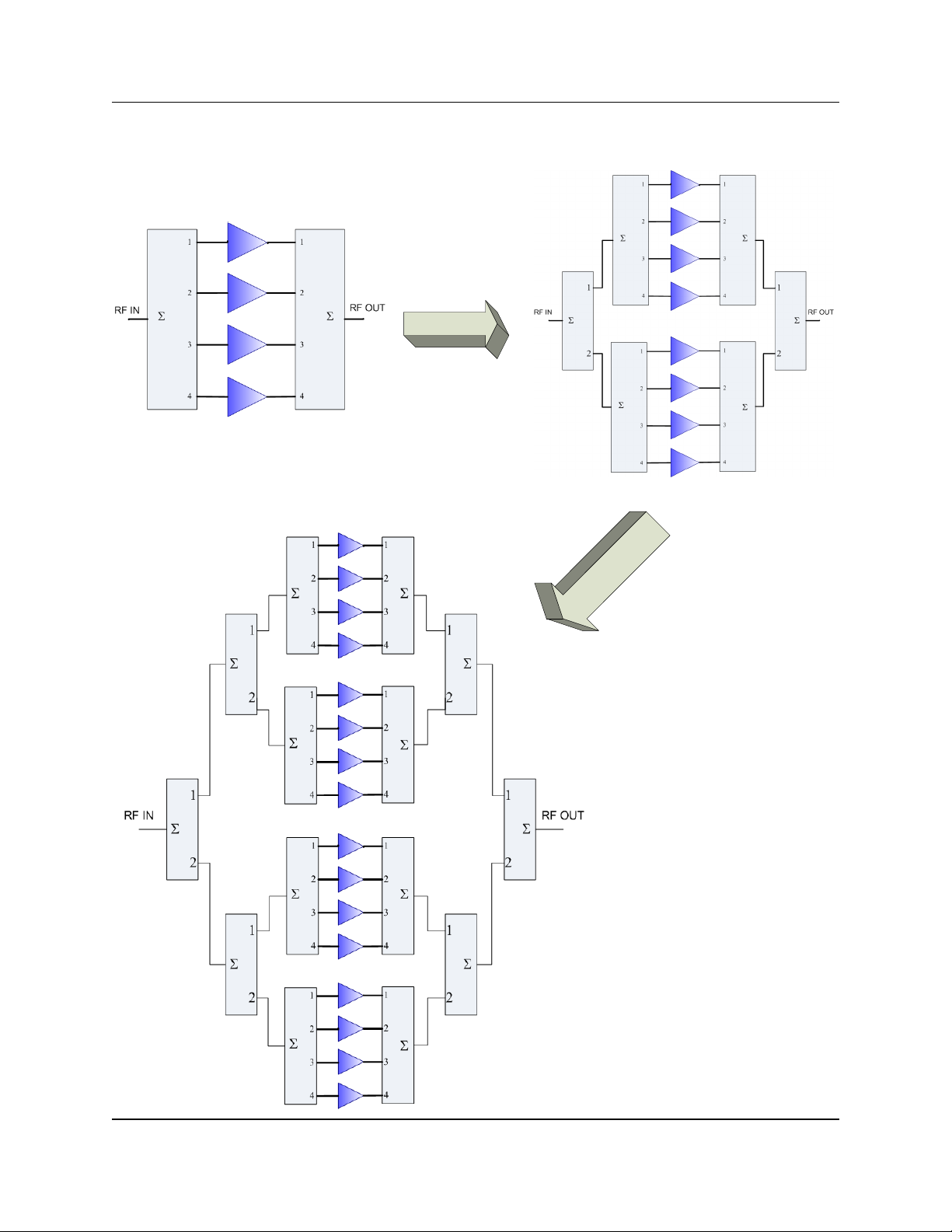
Figure 1-1 shows a simplified block diagram of the various system configurations.
Figure 1-1: System Block
Diagrams of 4-Module,
8-Module and 16-Module
PowerMAX Systems
4-Module System
8-Module System
16-Module System
14 214579 REV C PowerMAX SSPA System Operations Manual
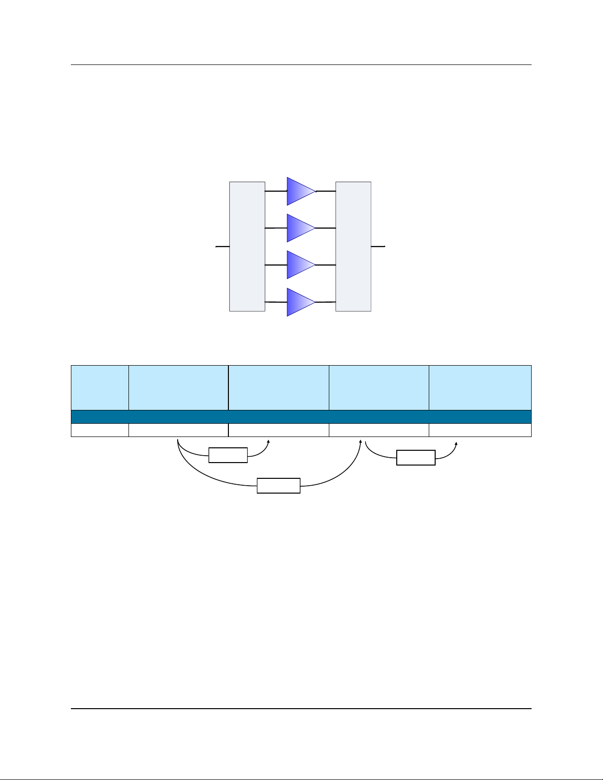
1.1.1 Four-Module Systems
Figure 1-2 displays a simple block diagram of a Four -Module PowerMAX system.
Table 1-2 shows an example of maximum and redundant output powers at P
sat
and P
Linear
for Four-Module PowerMAX systems. Refer to the specification sheet in Ap-
pendix C for a full list of available power levels and output powers in the Four-Module
configuration.
2
1
3
4
2
1
3
4
RF IN
RF OUT
Table 1-2: Four-Module PowerMAX System Output Power Example
SSPA
Module
Power
Level
Typical Maximum
Output Power
4-modules, P
sat
Maximum
Output Power
4-modules, P
Linear
Typical Redundant
Output Power
3-modules, P
sat
Redundant
Output Power
3-modules, P
Linear
C-Band
400 W GaN
61.5 dBm (1.4 kW) 58.5 dBm (700 W) 59.1 dBm (800 W) 56.1 dBm (400 W)
Figure 1-2: Block
Diagram of 4-Module
PowerMAX System
- 3 dBm
- 2.4 dBm
- 3 dBm
A four-module PowerMAX system which experiences a failure
in one module will have a 2.4 dBm reduction in output power.
PowerMAX SSPA System Operations Manual 214579 REV C 15
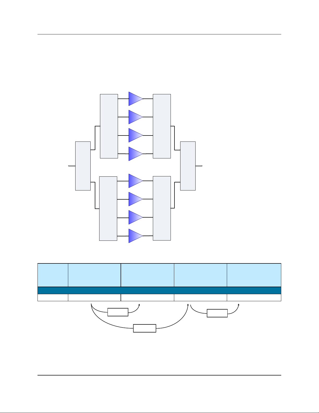
1.1.2 Eight-Module Systems
Figure 1-3 displays a simple block diagram of a Eight -Module PowerMAX system.
Table 1-3 shows an example of maximum and redundant output powers at P
sat
and P
Linear
for Eight-Module PowerMAX systems. Refer to the specification sheet in Ap-
pendix C for a full list of available power levels and output powers in the Eight-Module
configuration.
2
1
3
4
2
1
3
4
2
1
2
1
3
4
2
1
2
1
3
4
RF IN RF OUT
Table 1-3: Eight-Module PowerMAX System Output Power Example
SSPA
Module
Power
Level
Typical Maximum
Output Power
8-modules, P
sat
Maximum
Output Power
8-modules, P
Linear
Typical Redundant
Output Power
7-modules, P
sat
Redundant
Output Power
7-modules, P
Linear
C-Band
400 W GaN
64.3 dBm (2.6 kW) 61.3 dBm (1.3 kW) 63.1 dBm (2.0 kW) 60.1 dBm (1.0 kW)
Figure 1-3: Block
Diagram of 8-Module
PowerMAX System
- 3 dBm
- 1.2 dBm
- 3 dBm
An eight-module PowerMAX system which experiences a failure
in one module will have a 1.2 dBm reduction in output power.
16 214579 REV C PowerMAX SSPA System Operations Manual
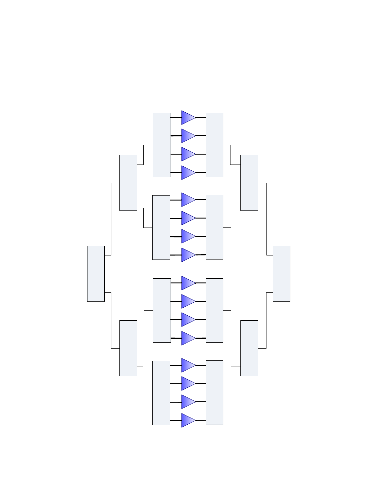
1.1.3 16-Module Systems
Figure 1-4 displays a simple block diagram of a 16-Module PowerMAX system. Table 1-4 shows an example of maximum and redundant output pow ers at P
sat
and
P
Linear
for 16-Module PowerMAX systems. Refer to the specification sheet in Appendix
C for a full list of available power levels and output powers in the 16-Module configura-
tion.
2
1
3
4
2
1
3
4
2
1
3
4
2
1
3
4
2
1
3
4
2
1
3
4
2
1
3
4
2
1
3
4
2
1
2
1
2
1
2
1
2
1
2
1
RF IN RF OUT
Figure 1-4: Block Diagram of 16-Module PowerMAX System

PowerMAX SSPA System Operations Manual 214579 REV C 17
1.2 Specifications
Refer to the specification sheet in Appendix C for complete specifications.
1.3 Inspection
When the unit is received, an initial inspection should be completed. First ensure that
the shipping container is not damaged. If it is, have a representative from the shipping
company present when the container is opened. Perform a visual inspection of the
equipment to make sure that all items on the packing list are enclosed. If any damage
has occurred or if items are missing, contact:
Teledyne Paradise Datacom
328 Innovation Blvd., Suite 100
State College, PA 16803 USA
Phone: +1 (814) 238-3450
Fax: +1 (814) 238-3829
1.4 Shipment
To protect the SSPA Chassis during shipment, use high quality commercial packing
methods. When possible, use the original shipping container and its materials. Reliable
commercial packing and shipping companies have facilities and materials to adequately repack the instrument.
Table 1-4: 16-Module PowerMAX System Output Power Example
SSPA
Module
Power
Level
Typical Maximum
Output Power
16-modules, P
sat
Maximum
Output Power
16-modules, P
Linear
Typical Redundant
Output Power
15-modules, P
sat
Redundant
Output Power
15-modules, P
Linear
C-Band
400 W GaN
67.0 dBm (5.0 kW) 64.0 dBm (2.5 kW) 66.4 dBm (4.3 kW) 63.4 dBm (2.1 kW)
- 3 dBm
- 0.6 dBm
- 3 dBm
A 16-module PowerMAX system which experiences a failure
in one module will have a 0.6 dBm reduction in output power.
18 214579 REV C PowerMAX SSPA System Operations Manual
1.5 Safety Considerations
Potential safety hazards exist unless proper precautions are observed when working
with this unit. To ensure safe operation, the user must follow the information, cautions
and warnings provided in this manual as well as the warning labels placed on the unit.
1.5.1 High Voltage Hazards
High Voltage, for the purpose of this section, is any voltage in excess of 30V. Voltages
above this value can be hazardous and even lethal under certain circumstances. Care
should be taken when working with devices that operate at high voltage.
All probes and tools that contact the equipment should be
properly insulated to prevent the operator from coming in
contact with the voltage.
The work area should be secure and free from non-
essential items.
Operators should never work alone on high voltage de-
vices. There should always be another person present in
the same work area to assist in the event of an emergency.
Operators should be familiar with procedures to employ in the event of an
emergency, i.e., remove all power, CPR, etc.
An AC powered unit will have 115 VAC or 230 VAC entering through the
AC power connector. Caution is required when working near this con-
nector, the AC circuit breaker, or the internal power supply.
1.5.2 High Current Hazards
Many high power devices are capable of producing large surges of current. This is true
at all voltages, but needs to be emphasized for low voltage devices. Low voltage
devices provide security from high voltage hazards, but also require higher current to
provide the same power. High current can cause severe injury from burns and
explosion. The following precautions should be taken on devices capable of
discharging high current:
Remove all conductive personal items (rings, watches,
medals, etc.)
The work area should be secure and free of non-essential
items.
Wear safety glasses and protective clothing.
Operators should never work alone on high risk devices.
There should always be another person present in the
same area to assist in the event of an emergency.
Operators should be familiar with procedures to employ in the event of an
emergency, i.e., remove all power, CPR, etc.
HIGH
CUR-
PowerMAX SSPA System Operations Manual 214579 REV C 19
Large DC currents are generated to operate the RF Module inside of the enclosure.
EXTREME CAUTION IS REQUIRED WHEN THE ENCLOSURE IS OPEN AND THE
AMPLIFIER IS OPERATING. DO NOT TOUCH ANY OF THE CONNECTIONS ON
THE RF MODULES WHEN THE AMPLIFIER IS OPERATING. CURRENTS IN EXCESS OF 60 AMPERES MAY EXIST ON ANY ONE CONNECTOR.
1.5.3 RF Transmission Hazards
RF transmissions at high power levels may cause eyesight damage and skin burns.
Prolonged exposure to high levels of RF energy has been linked to a variety of health
issues. Please use the following precautions with high levels of RF power.
Always terminate the RF input and output connector prior
to applying prime AC input power.
Never look directly into the RF output waveguide
Maintain a suitable distance from the source of the trans-
mission such that the power density is below recommended guidelines in ANSI/IEEE C95.1. The power density specified in ANSI/IEEE C95.1-1992 is 10 mW/cm2.
These requirements adhere to OSHA Standard 1910.97.
When a safe distance is not practical, RF shielding should be used to
achieve the recommended power density levels.
1.5.4 Electrical Discharge Hazards
An electric spark can not only create ESD reliability problems, it can also cause serious
safety hazards. The following precautions should be followed when there is a risk of
electrical discharge:
Follow all ESD guidelines
Remove all flammable material and solvents from the area.
All probes and tools that contact the equipment should be proper-
ly insulated to Prevent electrical discharge.
The work area should be secure and free from non-essential
items.
Operators should never work alone on hazardous equipment.
There should always be another person present in the same work area to
assist in the event of an emergency.
Operators should be familiar with procedures to employ in the event of an
emergency, i.e., remove all power, CPR, etc.
1.5.5 Tipping Hazard
To avoid risk of bodily injury, follow all instructions for maintaining the stability of the
equipment during transport, installation and maintenance.
RF
SIGNAL
20 214579 REV C PowerMAX SSPA System Operations Manual
The PowerMAX system is designed to be installed on a level
surface. Any attempt to install the cabinet on an uneven surface
may cause the cabinet to tip over, which may result in bodily
injury.
If the system includes the optional cabinet exhaust fans, do not
remove any of the SSPA chassis from the cabinet while the
exhaust fan door is open unless the cabinet is secured to the floor.
1.5.6 High Potential for Waveguide Arcing
As with all systems which utilize high power signals within
waveguide, the potential exists for an electric arc to form.
To minimize this risk, Teledyne Paradise Datacom requires all waveguide be pressurized and dehydrated.
1.6 Waveguide Pressurization and Dehydration
When working with high power amplifier systems that operate into waveguide, the inadvertent creation of arcs is always a concern. An arc in waveguide is the air discharge
breakdown due to the ionization of the air molecules by electrons. This breakdown in
waveguide occurs when the rate of electron production becomes greater than the loss
of electrons to diffusion to the surrounding walls.
It is extremely difficult to precisely predict the power levels at which the breakdown occurs. It is dependent on a variety of factors but the primary factors are:
Waveguide temperature and atmospheric pressure
Components in the Waveguide Transmission System such as: Flanges,
Bends, Tees, Combiners, Filters, Isolators, etc.
Load VSWR presented to the amplifier.
When operating such a high power amplifier system it is imperative that the waveguide
transmission system be dehydrated and pressurized. Operation with an automatic air
dehydrator will provide dry pressurized air to ensure that condensation cannot form in
the waveguide. Also the higher the pressure that can be maintained in the waveguide;
the higher the power handling is in the waveguide system. Most commonly available
air dehydrators are capable of providing pressures of 0.5 to 7.0 psig (25-362 mmHg).
At low power levels (uniform field distribution), low pressure can give good results. For
non-uniform conditions, highly localized breakdown can occur. In this case the wave-
guide system will require much higher pressure. This occurs with bends, waveguide
flange joints. If line currents flow across a small gap introduced by poor tolerances,
flange mismatch, poorly soldered bends, field strengths in excess of that in the main
line can occur in the gap. Pressurization with air or high dielectric gases can increase
the power handling by factors of 10 to 100.
PowerMAX SSPA System Operations Manual 214579 REV C 21
In High Power Amplifier systems an arc will travel from where it is ignited back to the
amplifier. Typical arc travel speed is on the order of 20 ft/sec. Increasing the waveguide pressure can reduce the speed of arc travel. It is difficult to get an accurate calculation of the amount of pressurization needed, but it is a good practice to get as
much pressure as your system can handle. All high power systems that meet the criteria of Table 1-5 are pressure tested at the factory to 1.5 psig. As a guide we rec-
ommend using the power levels in Table 1-5 as the threshold levels w here special
attention be given to dehydration and the overall simplification of waveguide system
design.
It is a common misconception to look up the maximum theoretical power handling of a
particular type of waveguide and assume that this is the maximum power handling.
This may be the case for a straight waveguide tube with ideal terminations but these
values must be significantly de-rated in practical systems. Phase combined amplifier
systems can be particularly sensitive to the potential for waveguide arcing. This is due
to the numerous bends, magic tees, multiple waveguide flange joints, and other wave-
guide components. Table 1-6 shows the power handling capability of some popu-
lar waveguide components normalized to the waveguide power rating. From this table,
we can see how a practical waveguide system’s power handling will de-rate significantly.
Table 1-6: Relative De-rating of Popular Waveguide
Components Relative to Straight Waveguide
Waveguide Component Relative Power Rating
H Plane Bend 0.6 to 0.9
E Plane Bend 0.97
90o Twist 0.8 to 0.9
Magic Tee 0.80
E-Plane Tee 0.06
H-Plane Tee 0.80
Cross Guide Coupler 0.21
Table 1-5: Recommended Output Power Thresholds
for Waveguide System Pressurization
Satcom Band Frequency Range Amplifier Output Power Waveguide
S Band 1.7-2.6 GHz > 10 kW WR430
C-Band 5.7 - 6.7 GHz > 2 kW WR137
X-Band 7.9-8.4 GHz > 1kW WR112
Ku-Band 13.75-14.5 GHz > 500W WR75
Ka-Band 27-31 GHz > 100W WR28
22 214579 REV C PowerMAX SSPA System Operations Manual
Most waveguide systems have many of these components integrated before reaching
the antenna feed. It is not uncommon for a Satcom waveguide network to de-rate to
5% of the straight waveguide power rating.
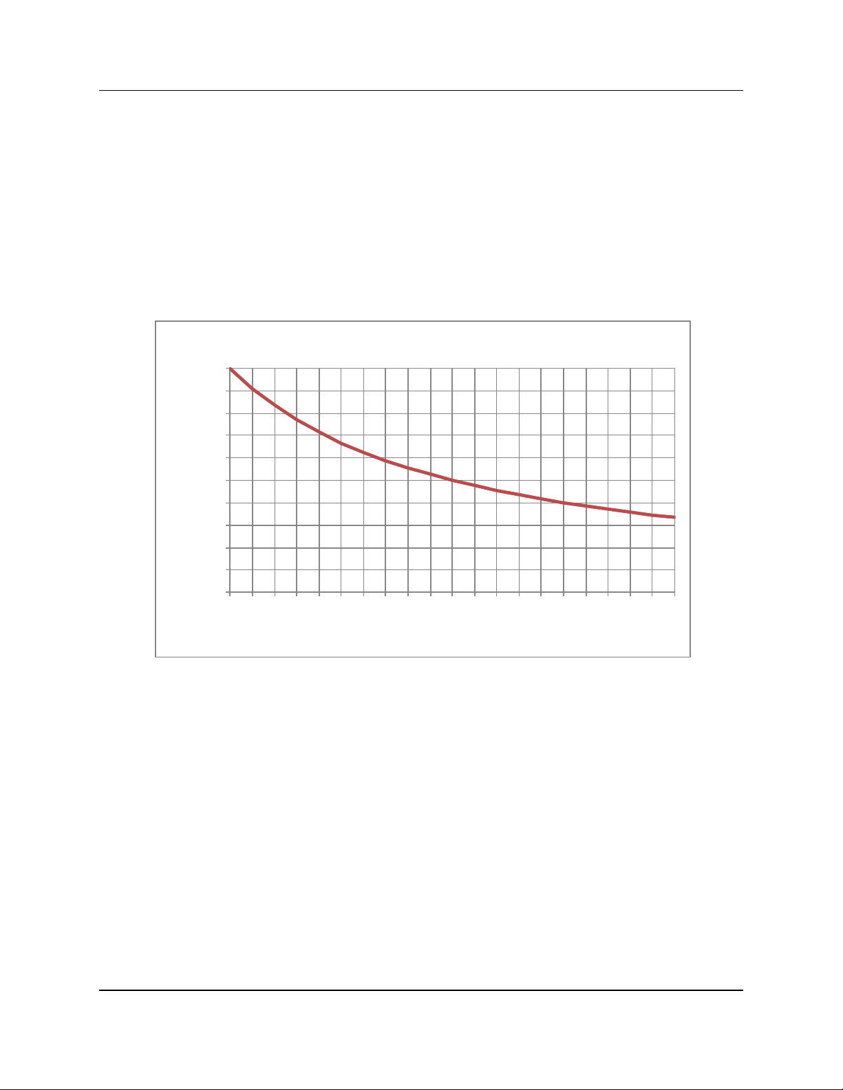
The load VSWR also has an impact on the breakdown threshold in waveguide networks. Standing waves degrade the power handling of any transmission line network.
The graph of Figure 1-5 shows the rapid degradation of waveguide breakdown vs.
load VSWR. The chart shows that for a 2.0:1 load VSWR, the breakdown potential will
be half of what it would be with a perfectly matched load. This can degrade even more
when high Q elements such as band pass filters are included in the waveguide network.
There are many factors to consider with high power amplifier systems in terms of the
output waveguide network. Especially when using HPA systems with output power
levels of Table 1-5, it is imperative to ensure that the output waveguide network is
pristinely clean and dry. An appropriate dehydrator should be used with capability of
achieving adequate pressure for the system’s output power. Take extra precaution to
make sure that any waveguide flange joints that are not already in place at the factory
are properly cleaned, gasket fitted, and aligned. A properly designed and maintained
waveguide network will ensure that no arcing can be supported and will provide many
years of amplifier service life.
0.00
0.10
0.20
0.30
0.40
0.50
0.60
0.70
0.80
0.90
1.00
1
1.1
1.2
1.3
1.4
1.5
1.6
1.7
1.8
1.9
2
2.1
2.2
2.3
2.4
2.5
2.6
2.7
2.8
2.9
3.0
Power Degradation Ratio
Load VSWR
Degradation of Breakdown Power by VSWR
Figure 1-5: Degradation of Breakdown Power by VSWR
PowerMAX SSPA System Operations Manual 214579 REV C 23
2.0 Introduction
This section contains descriptions of the various components of a PowerMAX SSPA
System. These include the SSPA Chassis, the Power Supply Chassis, the RF Distribution Panel, the optional AC Distribution Box and optional Ethernet Switch.
2.1 PowerMAX SSPA Chassis
The PowerMAX SSPA Chassis is a rack-mountable unit designed to fit in a standard
19” (483 mm) wide EIA rack. Each unit is 3 rack units or 5.22 inches (133 mm) high by
25.25 inches (641 mm) deep.
2.1.1 Front Panel Features
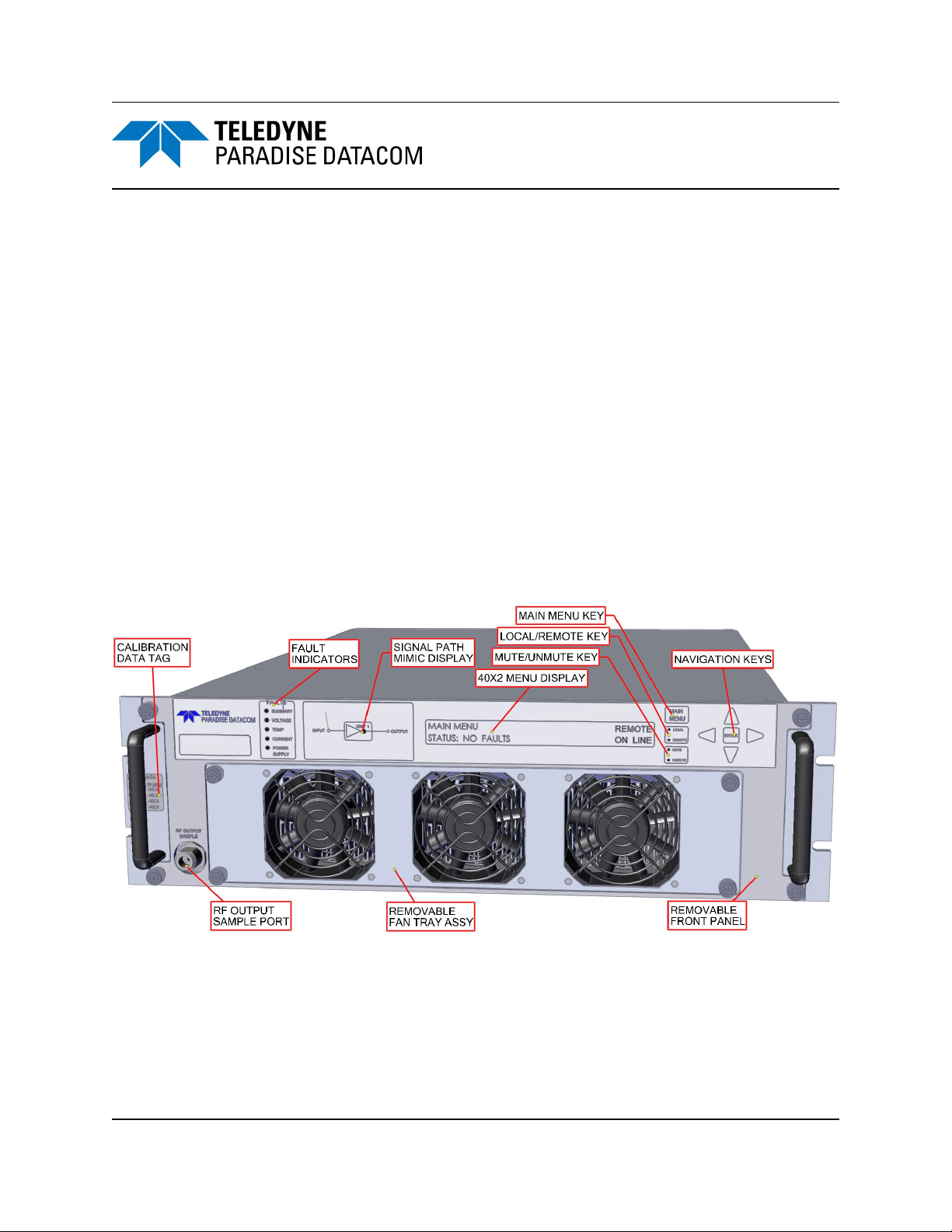
Figure 2-1 shows an illustration of the front panel view of a standard 3RU Rack
Mount chassis. The front panel features five (5) fault condition LEDs, a master/slave
indicator, a 40x2 character display, navigation keys, removable fan assembly and RF
sample port. The entire front panel may be removed to access the SSPA module.
2.1.1.1 Fault Condition LEDs
The RM SSPA has five fault condition LEDs on left side of the front panel which reflect
some of the HPA major faults plus the summary fault state.
Section 2: System Components
Figure 2-1: PowerMAX SSPA Chassis Front Panel

24 214579 REV C PowerMAX SSPA System Operations Manual
2.1.1.2 Master/Slave Indicator
When in N+1 Mode, pressing this key will put the designated HPA into Master Mode.
The LED beside this key will light when the HPA is in Master mode. If the LED is not
lit, the unit is in Slave Mode.
2.1.1.3 Front Panel Display
The front panel 40x2 character display allows the user to get detailed information
about state of the HPA and provides easy customization of operation through an
inter-active menu structure. See Section 5 for a full description of the menu structure
available through the front panel display.
2.1.1.4 Navigation Keys
The Up Arrow (▲), Down Arrow (▼), Left Arrow (◄), Right Arrow (►) and Enter
keys on the right side of the front panel allow the user to navigate through the menu
selections displayed on the front panel display.
2.1.1.5 Main Menu Key
Provides a shortcut to the SSPA main menu. See Section 5 for a complete description
of the menu selections and operation.
2.1.1.6 Local/Remote Key
Allows the user to disable or enable the local control keypad console. If the SSPA is in
"Remote Only" mode, the unit will not react on any keystrokes except the "Local/
Remote" key.
2.1.1.7 Mute/Unmute Key
Provides an easy way to change the Mute state of the SSPA. Muting the amplifier via
the front panel requires 100 msec maximum (50 msec minimum).
2.1.1.8 Output Sample Port [Type N (F)]
The Output RF Sample Port connector is located on the right lower corner of the HPA
front Panel. This provides a coupled sample of the RF output signal. A calibration tag
is located above the N-type (f) connector.
2.1.1.9 Removable Fan Assembly
The front panel fan assembly can be removed for maintenance. See Section 4 for
more details. The three-fan assembly operates at 20 VDC.
PowerMAX SSPA System Operations Manual 214579 REV C 25
2.1.1.10 Removable Face Plate
The entire front panel of the SSPA chassis is removable in order to access the SSPA
module. See Section 4, Troubleshooting and Maintenance for details on removing the
SSPA module from the chassis.
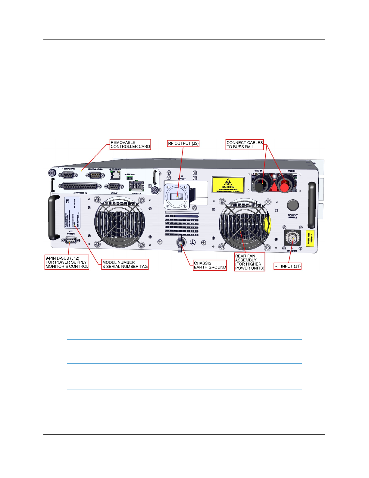
2.1.2 Rear Panel Features
Figure 2-2 shows the rear panel view of a standard DC input Rack Mount chas-
sis. The rear panel features the prime power connection, a removable Monitor & Control Card Assembly, removable fan assemblies, and the RF input and output ports.
2.1.2.1 RF Input Port (J1) [Type N (F)]
The type N female connector on the right side of the rear panel is used as the RF
input.
Note: Typical maximum RF input is +15 dBm.
2.1.2.2 RF Output Port (J2) [Band Specific]
Warning! Do not operate the amplifier without a termination or mating connection on the RF Output Port. RF Hazard warnings apply.
Never look directly into an open RF Output Port.
L- and S-Band units have a coaxial output using a Type N (F) connector. Higher
frequency units utilize waveguide output flanges.
Figure 2-2: SSPA Rear Panel (Ku-Band shown)
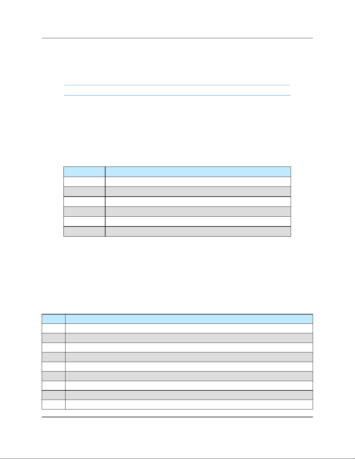
26 214579 REV C PowerMAX SSPA System Operations Manual
C-Band: WR137 with a CPRG-137 grooved flange;
X-Band: WR112 with a CPRG112 grooved flange;
Ku-Band: WR75 with a circular grooved flange;
Ka-Band: WR28 with a circular grooved flange.
Note: Custom frequencies may use different w aveguide sizes.
2.1.2.3 Switch Port (J3) [6-pin MS-type]
A 6 pin Molex connector header with blind insertion system guides (mates with Molex
P/N 39-01-2060) is used in a 1:1 Redundancy System to provide switching for the
waveguide transfer switch (RF Switch). Table 2-1 shows the pin outs for the Switch
Port (J3).
2.1.2.4 Serial Main (J4) [DB9 (F)]
A DB9 female connector serves as primary remote control interface connector. The
interface is re-configurable through the front panel or can be used as a RS-232 or
RS-485 interface (2 or 4 wires). The RS-485 TX and RX pairs must be twisted for maximum transmission distance. A user-configurable 120-ohm termination resistor is provided on the same connector. Table 2-2 shows the Serial Main (J4) connector pin
outs.
Table 2-2: Serial Main (J4) pin outs
Pin # Function / Description
1 RS485 TX+ (HPA Transmit +)
2 RS485 TX- (HPA Transmit -)/RS232 TX
3 RS485 RX- (HPA Receive -)/RS 232 RX
4 RS485 RX+ (HPA Receive +)
5 GND
6 Service Request 1 Form C relay NC contact (Closed on HPA Summary Fault)
7 Service Request Common Form C relay common contact
8 Service Request 2 Form C relay NO contact (Opened on HPA Summary Fault)
9 120 ohm termination (must be connected to pin 4 to enable termination)
Table 2-1: Switch Port (J3) pin outs
Pin # Function / Description
1 +28V Switch Drive Output. 3 Amp over current protection.
2 Switch 1 Position 2 drive
3 Switch 1 Position 1 drive
4 +28V Switch Drive Output. 3 Amp over current protection.
5 Switch 2 Position 2 drive
6 Switch 2 Position 1 drive

PowerMAX SSPA System Operations Manual 214579 REV C 27
2.1.2.5 Serial Local (J5) [DB9 (M)]
This DB9 male connector is used in advanced system integration and for system
debugging purposes. Leave unconnected unless specified otherwise.
2.1.2.6 Service Port (J6) [Mini USB]
A 5-contact Mini USB connector is used to provide on field flash re-programmability for
the HPA controller card. In order to reload controller board firmware, connect this port
to a PC Parallel port through straight through cable. See Section 4.1.5 for a description
of the firmware upgrade procedure.
2.1.2.7 Parallel I/O (J7) [DB37 (F)]
A DB37 female type connector, the Parallel I/O port contains a series of contact
closures for monitoring HPA faults as well as opto-isolated inputs for controlling some
HPA functions. Inputs react on the closure to ground. The minimal closure time is
50mS. See Table 2-3 on the next page for a description of this connector ’s pin-
outs.
2.1.2.7.1 Hardware Mute (Tx Enable)
There are three ways to mute the amplifier via hardware input:
1. A 50 ms closure to ground on Port J7, Pin 17 to toggle between Mute/
Unmute states;
2. Press the Main Menu key on the front panel, then select 4.Fault Setup and
press the Enter key; select 2.Auxiliary Faults and press the Enter key; select
1.Action and press the Enter key; select 4.Alert+Mute and press the
Enter key. Then select 4.Fault Setup and press the Enter key; select
2.Auxiliary Faults and press the Enter key; select 2.Fault Logic and
press the Enter key; select 2.Fault on Low and press the Enter key. A contin-
uous closure to ground on Port J7, Pin 18 will then mute the amplifier. See
Section 5.1.4.2;
3. Press the Main Menu key on the front panel, then select 4.Fault Setup and
press the Enter key; select 2.Auxiliary Faults and press the Enter key; select
1.Action and press the Enter key; select 4.Alert+Mute and press the Enter key. Then select 4.Fault Setup and press the Enter key; select
2.Auxiliary Faults and press the Enter key; select 2.Fault Logic and
press the Enter key; select 2.Fault on High. A continuous open to ground on
Port J7, Pin 18 will mute the amplifier. See Section 5.1.4.2.
2.1.2.8 Link Port (J8) [DB9 (F)]
The 9-pin female connector J8 Link Port is used to link a SSPA with other units in a
redundant system in order to pass online/standby status information between them.
Leave unconnected unless specified otherwise. See Section 3.1.5.

28 214579 REV C PowerMAX SSPA System Operations Manual
Table 2-3: Parallel I/O (J7) pin outs
Pin # Function / Description
1 Closed on Power Supply Fault Form C relay NC
2 Open on Power Supply Fault Form C relay NO
20 Power Supply Fault Common
21
1. Standalone mode. Closed on Auxiliary Fault
2. 1:1 Redundancy Mode. Closed on Automatic switchover mode. Form C relay NC
22
1. Standalone Mode. Open on Auxiliary Fault
2. 1:1 Redundancy Mode. Closed on Manual switchover mode. Form C relay NO
3 Auxiliary Fault\Auto-Manual Common
4 Open on Mute. Form C Relay NC
5 Closed on Mute. Form C Relay NO
23 Mute Status Common
24 Closed on BUC Fault. Form C Relay NC
25 Open on BUC Fault. Form C Relay NO
6 BUC Fault Common
7 Closed on High Temperature Fault. Form C Relay NC
8 Open on High Temperature Fault. Form C Relay NO
26 High Temperature Fault Common
27
1. Standalone mode. Closed on Regulator Low Voltage Fault
2. 1:1 Redundancy Mode. Closed on HPA Standby. Form C relay NC
28
1. Standalone Mode. Open on Regulator Low Voltage Fault.
2. 1:1 Redundancy Mode. Closed on HPA Online Mode. Form C relay NO
9 Regulator Low Voltage Fault\Standby-Online Common
10 Closed on DC Current Low Fault. Form C Relay NC
11 Open on DC Current Low Fault. Form C Relay NO
29 DC Current Low Fault Common
30 Closed on Low Forward RF Fault. Form C Relay NC
31 Open on Low Forward RF Form C Relay NO
12 Low Forward RF Fault Common
16 Auto/Manual toggle input. 50mS Closure to isolated ground to activate
17 Mute/Unmute toggle input. 50mS Closure to isolated ground to activate
18 Auxiliary Fault & Auxiliary Mute Input (See Section 2.1.2.7.1). 50 ms min. response
35 HPA Standby input. 50mS Closure to isolated ground to activate
36 Local/Remote toggle. 50mS Closure to isolated ground to activate
37 Fault clear. 50mS Closure to isolated ground to activate
19 Isolated Signal Ground
15 +5V Isolated Power 20 mA
13, 32 +28V Auxiliary Power 1A
14, 33 Chassis Ground
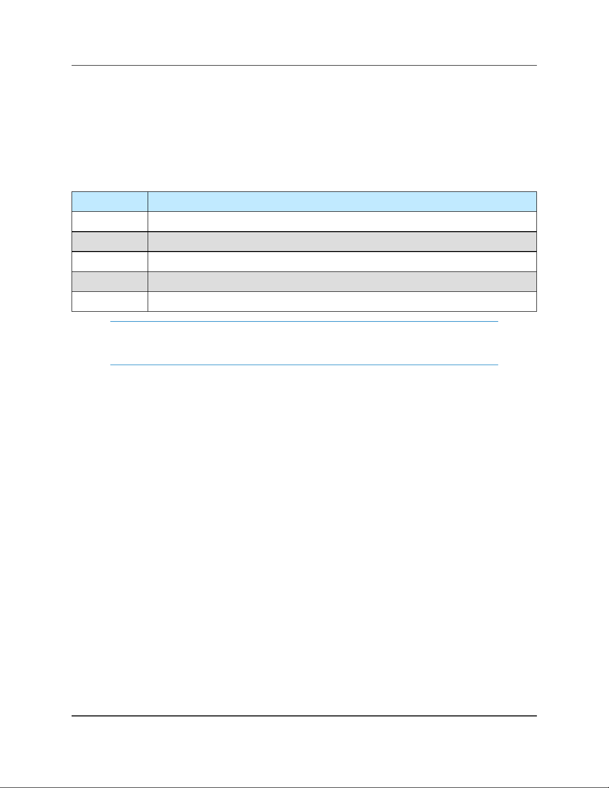
PowerMAX SSPA System Operations Manual 214579 REV C 29
2.1.2.9 Ethernet Port (J9) [RJ45]
This is a RJ45 connector with integrated magnetics and LEDs. This port becomes the
primary remote control interface when the Interface option is selected to “IPNet” as
described in Section 6.6. This feature allows the user to connect the SSPA to a 10/100
Base-T office Local Area Network and have full-featured Monitor & Control functions
through a web interface. See Table 2-5 for Ethernet pin outs.
Note: IP address, Gateway address, Subnet mask, IP port and IP
Lock address needs to be properly selected prior to first use (see Appen-
dix A for details).
LED lamps on the connector indicate network status. A steady Green light indicates a
valid Ethernet link; a flashing Yellow LED indicates data transfer activity (on either the
Transmit and Receive paths).
2.1.2.10 Power Supply M&C/Alarm (J12) [DB9 (M)]
Port J12 is the Power Supply M&C/Alarm connection, which passes information
between a connected N+1 Power Supply and the SSPA. Depending on the system
configuration, the connected cable assembly may include connections to one or more
power supplies. See Section 3.1.8.
2.1.2.11 Removable Rear Fan Assembly
Certain higher power level amplifiers include a pair of exhaust fan assemblies at the
rear panel. These fans can be removed for maintenance or replacement without taking
the amplifier offline. See Section 4.1.1. Each of the two rear fans operate at 24 VDC.
The fans should spin when power is applied to the chassis.
Table 2-4: Ethernet Port (J9) pin outs
Pin # Function / Description
1 TX+
2 TX-
3 RX+
6 RX-
4,5,7,8 GND
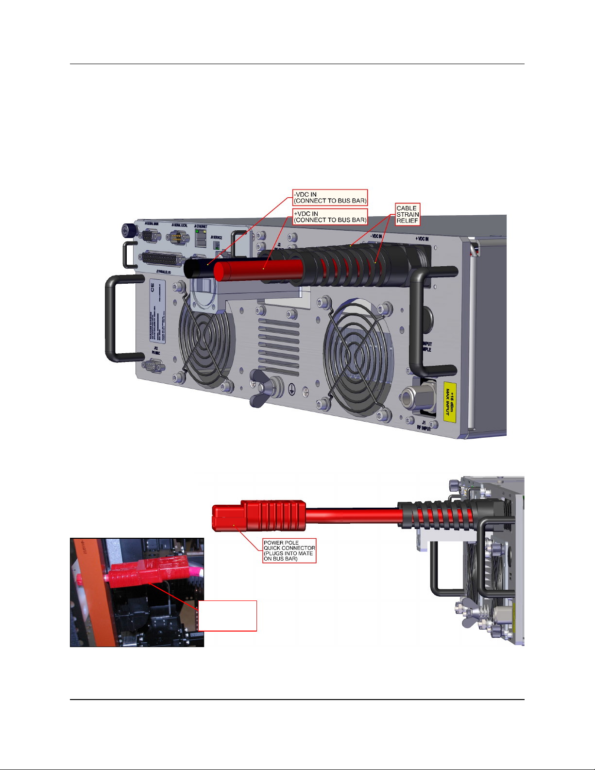
30 214579 REV C PowerMAX SSPA System Operations Manual
2.1.2.12 DC Input Port
The amplifier’s prime power connectors connect to the system’s bus rail assembly,
which provides DC input provided by the N+1 Redundant Power Supplies. See Table
2-5 for an example of system input power requirements.
Each amplifier connects to the system cabinet’s bus rail via a quick-connect DC cable
assembly. See Figure 2-3 and Figure 2-4.
Figure 2-3: DC Input Cables with Strain Relief
Figure 2-4: Connect Power Cables Between SSPA and Bus Rail
PLUG POWER POLE
QUICK CONNECTOR
INTO BUS BAR
MATING CONNECTOR

PowerMAX SSPA System Operations Manual 214579 REV C 31
2.2 Power Supply Chassis
System prime input power is achieved via a number of 1RU power supply chassis
(depending on the system power requirements), each of which houses up to four (4)
2.5 kW power supply modules. Power is distributed from the power supplies to the
SSPA modules via a bus rail assembly.
All of the power supply modules are active and share the load current supplied to the
amplifier. The power supply module current capacity is chosen such that at least one
extra module is included over the amplifier’s current requirement. This is to say that the
power supply is n+1 redundant. The amplifier will continue to operate normally in the
presence of one power supply module failure.
The failed module can be changed without ever taking the system out of service. Simply extract the failed module out of the rack, and plug in a replacement. See Figure 2-5.
An example of the input power requirements for PowerMAX system configurations
using a C-Band 400W GaN SSPA Module is shown in Table 2-5.
Refer to the specification sheet in Appendix C for a full list of power requirements for
the available PowerMAX system configurations.
SSPA
Module
Power
Level
4 Chassis System 8 Chassis System 16 Chassis System
Required
Input Power @ P
sat
Required
Input Power @ P
sat
Required
Input Power @ P
sat
C-Band
400W GaN 7,200 W 14,400 W 28,800 W
Table 2-5: Prime Input Power Example (400W GaN C-Band SSPA Module)
Figure 2-5: 1RU Power Supply Module Insertion/Extraction

32 214579 REV C PowerMAX SSPA System Operations Manual
In keeping with the redundancy architecture of the power supply, there are individual
AC input for each power supply module. DC outputs are in a bus bar configuration.
See Figure 2-6.
The standard 24V AC input configuration for the 2.5 kW power supply is 100-240 VAC
single phase, 47-63 Hz, 0.99 power factor per module. A separate AC input transformer could feed each AC input.
Connect the first line/hot to L1, the second line or neutral to L2/N, and finally your AC
ground to GRD. Tighten screws to 6 in-lbs. The connection identification is given below:
Chassis Earth - Green/Yellow
Line - Brown
Neutral - Blue
The DC output from each power supply is connected to the system bus bar. The power
cables are bolted to the bus bars of the power supply, as shown in Figure 2-7. The
other end of the cable snaps into the power pole connector attached to the system bus
bar. See Figure 2-8.
Figure 2-6: 1RU Power Supply AC Line Inputs/Outputs
+ -
DC Outputs
+ -
DC Outputs
Figure 2-7: Connect Cables to Power Supply DC Output Bus Bar
Figure 2-8: Connect Cables to System Bus Bar

PowerMAX SSPA System Operations Manual 214579 REV C 33
2.2.1 AC Distribution Panel (Optional)
When utilizing the optional AC Distribution Panel, prime power may be introduced into
a series of terminal blocks at the top of the cabinet. The system may be powered via
either single-phase or three-phase power, depending on customer requirements.
Electrical conduit is routed between the terminal block and a 5RU boxed assembly, the
AC Distribution Panel, which provides a circuit breaker for each line out (See Figure 2-
10). Power cables are run between the AC Distribution Panel and the AC inputs of
each power supply chassis.
When power is introduced to the system terminal blocks, and the circuit breakers are
closed, the fans on the power supply modules should start to spin, and the green LEDs
on the front of each module should light.
Figure 2-10: AC Distribution Panel
Figure 2-9: AC Terminal Block, Example

34 214579 REV C PowerMAX SSPA System Operations Manual
2.2.2 DC Distribution Panel
If auxiliary power is needed, the PowerMAX system uses one
or more DC Distribution Panels.
Each DC Distribution Panel uses Anderson Power PP45 connectors, and delivers up to 40 amps total through 5 outlets. See
Figure 2-11.
Input power is introduced from the Bus Bars to the Distribution
Panel’s DCIN connector. The DC Distribution Panel comes
supplied with ATC/ATO automotive blade fuses installed, a 40
Amp fuse at the DCIN connector, and 10 Amp fuses at ports
1-5. Each panel output is safe up to 40 amps but the total current capacity of the distribution panel is also 40 amps. Each
power output position that is in use must include a fuse.
Note that each fuse position has a LED blown fuse indicator
that will light up if an output fuse is blown. There must be power to the DC Distribution Panel and a load on the circuit that
has the blown fuse for the blown fuse LED to light.
Warning! Attempts to bypass or short across the fuses are dangerous and will void the warranty.
Figure 2-11: DC
Distribution Panel

PowerMAX SSPA System Operations Manual 214579 REV C 35
2.3 RF Distribution Panel
Each system cabinet is populated with a RF distribution panel which splits a single RF
input signal to each of the SSPA Chassis in the cabinet. The Reference Distribution
Panel also provides Input and Output sample ports for signal testing purposes. See
Figure 2-12.
2.3.1 J1 to J8 RF Out - SSPA # [Type N (F)]
Accessible from the rear panel of the RF Distribution box, these Type N (F) connectors
are attached via coaxial cables (provided) to the RF In (Port J1) of the system cabinet’s
SSPAs (SSPA 1 to SSPA 4 in a 4-module system; or SSPA 1 to SSPA 8 in a 8-module
system), as noted on the label located under each connector.
2.3.2 J9 RF In [Type N (F)]
This port at the rear of the RF Distribution panel provides a connection for the primary
RF Input of the system.
2.3.3 J10 Sample [Type N (F)]
This port at the rear of the RF Distribution panel is provided to pass a sample of the
system RF Output to the front panel RF Output Sample Port, J12.
2.3.4 J11 RF Input Sample [Type N (F)]
This port provides a -10 dBc sample of the RF Input signal fed through Port J9.
Figure 2-12: RF Distribution Panel, front and rear views
J12 RF OUTPUT
SAMPLE
SSPA 8SSPA 7
SAMPLE
J11 RF INPUT
SSPA 4 8-WAY PH-ADJ SSPA 6SSPA 3SSPA 2
RF OUT-SSPA 6SAMPLE RF OUT-SSPA 5RF OUT-SSPA 4
J10 J4
RF OUT-SSPA 3
J5 J3
RF INRF OUT-SSPA 2
8-WAY
J13
J15
OUT
RF
J6
INPUT
8-WAY
J14
INPUT
4-WAY
J16
OUT
RF OUT-SSPA 1RF OUT-SSPA 7
J2 J7
RF OUT-SSPA 8
J1 J8 J9
8-WAY
INPUT
SAMPLE
J10
RF OUT-SSPA 4J4RF OUT-SSPA 5
J5
RF OUT-SSPA 6RF OUT-SSPA 3
J3 J6
RF OUT-SSPA 2
4-WAY
INPUT
8-WAY
OUT
OUT
RF
J15
J13
J16
J14
RF OUT-SSPA 7
J2 J7
RF OUT-SSPA 1J1RF OUT-SSPA 8J8RF IN
J9

36 214579 REV C PowerMAX SSPA System Operations Manual
2.3.5 J12 RF Output Sample [Type N (F)]
This port provides a -55 dBc RF Output Sample of the signal fed through Port J10.
2.3.6 J13 RF Out [SMA]
Connects to J14 4-Way Input connector in a 4-module system (see Figure 2-12,
bottom figure), or to J15 8-Way Input connector in a 8-module system (see Figure
2-12, middle figure).
2.3.7 J14 4-Way Input [SMA]
Connects to J13 RF Out connector in a 4-module system (see Figure 2-12, bottom
figure), or to J16 8-Way Output connector in a 8-module system (see Figure 2-12,
middle figure).
2.3.8 J15 8-Way Input [SMA]
Connects to J16 4-Way Output connector in a 4-module system (see Figure 2-12,
bottom figure), or to J13 RF Out connector in a 8-module system (see Figure 2-12,
middle figure).
2.3.9 J16 8-Way Output [SMA]
Connects to J15 8-Way Input connector in a 4-module system (see Figure 2-12,
bottom figure), or to J14 4-Way Input connector in a 8-module system (see Figure
2-12, middle figure).
2.3.10 Phase Adjusters, SSPA 2-4 and SSPA 6-8
Accessible from the front panel, the phase adjustment screws may be used to tune the
phase adjustment of the individual amplifiers in the system in relation to the first SSPA
in each group of four SSPAs. See Figure 2-13. A separate phase adjuster is used to
adjust the phase between each groups of four SSPAs.
The phase adjustment of each system is
completed at the factory for optimum output
power across the frequency range. In the
event an amplifier fails and is replaced with
another amplifier with a slightly different
phase, the system will need to be adjusted
for best performance.
See Section 4, Troubleshooting and Mainte-
nance for direction on adjusting the phase
combining.
Figure 2-13: Phase Adjustment
Screws (Under Thumb Screws)

PowerMAX SSPA System Operations Manual 214579 REV C 37
2.4 Ethernet Switch (Optional)
The optional Ethernet Switch is a 16-port industrialtype 10 BASE-T/100 BASE-TX switch, mounted with a
metal DIN-rail clip to the rear top left of the cabinet.
The Ethernet Port (J9) of each SSPA Cabinet is
connected to a shielded RJ-45 port of the switch. See
Figure 2-14.
A power cable is provided to connect to the auxiliary
power connectors, as described in Section 2.2.1. A sin-
gle Ethernet cable links the switch to a shielded
RJ-45 port at the top of the cabinet.
No configuration of the switch is necessary. All ports
automatically configure data rate and duplex using the
Auto-negotiation protocol. Communication is set at
either 10 or 100 Mbps and at either half- or full duplex.
Each port will adapt to either straight-through or crossover cable using the Auto-MDIX protocol.
LED indicators of power, data rate and activity assist in
troubleshooting. The Link (L) LED will illuminate yellow
for 10 Mbps and green for 100 Mbps, and will flash
during activity. The Duplex (D) LED will illuminate
green at full-duplex, or will not illuminate for halfduplex. The power LED will illuminate green when
power is applied to the unit.
2.4.1 Ethernet Switch Specifications
Dimensions (WxHxD) : 6.02” x 3.73” x 1.61” (153 mm x 96 mm x 41 mm)
Power Requirements : 10-36 VDC or 24 VAC (±10%), provided through
quick-disconnect terminal strip
Operating Temperature: 0 to +60 °C
Relative Humidity : 10 - 95% non-condensing
Protection : IP30
Figure 2-14: Ethernet
Switch

38 214579 REV C PowerMAX SSPA System Operations Manual
2.5 Forward/Reflected Power Detector
The Forward/Reflected Power Detector box allows the user to introduce a sample of
both the system Forward RF power and the system Reflected RF power from the
waveguide output. This detector box circuitry will measure the amount of RF power
present in the sample, with a dynamic range of 12 dB starting at the maximum RF
output. For example, a system with 63.1 dBm (2 kW) of maximum forward RF would be
capable of reading reflected power levels from 51.1 dBm (130W) to 63.1 dBm (2 kW).
The amount of reflected power can is displayed on the front panel of the system’s
Master Unit; press the Main Menu key, select 1.Sys Info and press the Enter key.
2.5.1 Reflected Power Alarm
Because the reflected power circuitry is not a true VSWR measurement, but simply a
measure of absolute reflected power, it is possible to set an alarm level. The alarm level is factory pre-set at 80% of the HPA’s rated power. For example, an amplifier with 60
dBm (1 kW) of output power would have an alarm level set to 59 dBm (800W). The
alarm level is not user selectable due to possible frequent false alarms that may be
generated if set at a much lower level. The reflected power is reported to the M&C and
the user can set adjustable alarms using their M&C application.
Figure 2-15: Forward/Reflected RF Power Detector Box

PowerMAX SSPA System Operations Manual 214579 REV C 39
2.5.2 J40 Forward RF Sample In [SMA (F)]
A Forward RF Sample may be fed into port J40 of the detector box from a cross-guide
coupler on the system RF output.
2.5.3 J41 Reflected RF Sample In [SMA (F)]
A Reflected RF Sample may be fed into port J41 of the detector box from a crossguide coupler on the system RF output.
2.5.4 J42 RF Sample Out [SMA (F)]
Port J42 is the detector box’s RF Sample Port connector, and provides a coupled
sample of the system’s RF output signal.
2.5.5 J43 +12V Input [Pin]
The detector box is provided power from the Auxiliary Power Connectors described in
Section 2.2.1. A quick-disconnect cable is soldered to the RFI filter at J43 and the
adjacent turret terminal, and the connection end is plugged into the mating connector
on the line-in for the Auxiliary Power Connector.
2.5.6 J44 RS-485 Connector [DB9 (F)]
This DB9 female connector serves as the primary RS-485 (2 or 4 wires) serial remote
control interface connector. The detector box is included in the serial chain along with
the amplifiers in the system. See Table 2-2 for a pin-out of this connector.

40 214579 REV C PowerMAX SSPA System Operations Manual
THIS PAGE LEFT INTENTIONALLY BLANK

PowerMAX SSPA System Operations Manual 214579 REV C 41
3.0 Introduction
The PowerMAX SSPA System is available in three configurations: A four-chassis
system; an eight-chassis system; and a 16-chassis system. These systems should be
configured such that a failure of a single SSPA module can be tolerated by the system
power budget.
If Teledyne Paradise Datacom provides the cabinet, the 3RU Chassis (with SSPA
Module/Heatsink Assemblies removed), Power Supply Chassis (with Power Supply
Modules removed), and the waveguide assemblies and supports will be installed prior
to shipment, and the user simply needs to complete the installation.
Section 3: System Installation
RF OUTPUT
SAMPLE
RF OUTPUT
SAMPLE
RF OUTPUT
SAMPLE
RF OUTPUT
SAMPLE
J11 RF INPUT
SAMPLE
SSPA 2 SSPA 3 SSPA 4 8-WAY PH-ADJ SSPA 6 SSPA 7 SSPA 8
SAMPLE
J12 RF OUTPUT
RF OUTPUT
SAMPLE
RF OUTPUT
SAMPLE
RF OUTPUT
SAMPLE
RF OUTPUT
SAMPLE
RF OUTPUT
SAMPLE
RF OUTPUT
SAMPLE
RF OUTPUT
SAMPLE
RF OUTPUT
SAMPLE
J11 RF INPUT
SAMPLE
SSPA 2 SSPA 3 SSPA 4 8-WAY PH-ADJ SSPA 6 SSPA 7 SSPA 8
SAMPLE
J12 RF OUTPUT
Figure 3-1: 4-Chassis (Left) and 8-Chassis PowerMAX System Configurations

42 214579 REV C PowerMAX SSPA System Operations Manual
3.1 System Installation
The basic PowerMAX system consists of four (4) or eight (8) SSPA Chassis, one (1) to
four (4) N+1Power Supply Chassis, and an RF Distribution Panel. See Figure 3-1, left,
for the 4-module configuration; or Figure 3-1, right, for the 8-module set-up. The RF
output from each of the SSPA Chassis is phase combined into a single RF output
through the use of near loss-less four-way combiners. This passive combining array
provides a continuous signal, as opposed to switched arrays which cause a
momentary interruption of the RF output during switchover.
A 4-module system is configured so that the loss of a single SSPA module results in a
2.4 dB reduction in output power. An 8-module system is configured so if one SSPA
module fails, the system output power is only reduced by 1.2 dB. The PowerMAX
system automatically adjusts the gain to maintain constant gain with the loss of one,
two or three modules.
The cabinet should be uncrated and set upright prior to installing any of the SSPA
modules or Power Supply modules.
3.1.1 Uncrating the Equipment
Remove all equipment from the shipping containers prior to installation. Once the
equipment is unpacked, the crates and packing materials should be saved for future
use in the event that the equipment needs to be shipped elsewhere.
3.1.1.1 Uncrate the System Cabinet
Position the crate containing the cabinet as near the final installation point as possible.
If a winch or other load assisting mechanism is not available at the location, four to six
persons will be required to uncrate the cabinet and set it upright.
Remove the screws securing the crate lid to the rest of the crate. Remove and save
the crate lid. Remove the screws holding the shipping brackets to the sides of the
crate. See Figure 3-2. Remove and save the shipping brackets.
Figure 3-2: Remove and Save Shipping Brackets

PowerMAX SSPA System Operations Manual 214579 REV C 43
Remove the screws holding one side wall of the crate to the other sides and to the
base. Remove and save the side wall. Repeat for the other three crate side walls. See
Figure 3-3.
Remove the screws securing the 4x4 block at the base of the cabinet from the base of
the crate. Remove the 4x4 block and set aside. See Figure 3-3.
If the cabinet was sealed with a vacuum-sealed shrink-wrap barrier material, use a box
cutter to carefully cut away the barrier material while taking care not to damage the
cabinet or equipment.
3.1.1.2 Uncrate the SSPA Module/Heatsink Assemblies and Power Supplies
Each SSPA Module/Heatsink Assembly is boxed in its own cardboard, foam-lined container. The Power Supply Modules were each boxed in the OEM containers.
The power supply modules and SSPA Module/Heatsink Assemblies were packaged
together in larger crates for shipment.
Figure 3-3: Remove Crate Side Walls
4x4 Block

44 214579 REV C PowerMAX SSPA System Operations Manual
3.1.2 Setting Cabinet Upright
Teledyne Paradise Datacom recommends manually lifting the cabinet into the upright
position. This will require four to six persons capable of lifting a heavy load.
First, slide the cabinet so that the bottom of the cabinet hangs over the edge of the
crate base by approximately six (6) inches. See Figure 3-4.
With two people on either side near the top of the cabinet, lift the cabinet so that it tilts
towards the upright position. An overhead clearance of 95 inches (2413 mm) is required. See Figure 3-5.
Warning! Lift only by the cabinet frame! Lifting points are labeled.
Two additional people near the bottom of the cabinet can help guide the cabinet and
keep it from over-tipping.
Figure 3-4: Slide Cabinet So Base Hangs Over Edge of Crate Base
Figure 3-5: Lift Near Top of Cabinet to Tilt Cabinet Upright

PowerMAX SSPA System Operations Manual 214579 REV C 45
3.1.3 Inspect Waveguide
Ensure the SSPA RF Output waveguide is aligned with the waveguide attached to the
combiner assembly, and that the two segments of waveguide are secured together
with the appropriate hardware at each flange-to-flange connection.
3.1.4 Inspect Cables
The cable assemblies listed below were installed in the system cabinet prior to shipment from the factory. Each cable is labeled with its part number. The connectors on
each cable are labeled with the equipment identifier and port number where the connection will be made. Where possible, these connectors were secured to the equip-
ment using the connector bracket set screws.
Note: Refer to your system schematic to review all cable connections.
Ensure all cables are secured to the SSPA I/O panel.
Ensure all cables are secured to the RF Detector Module I/O panel. Refer to Section
2.5.
Ensure all power cables are connected to the bus bars (refer to Section 2.2) and DC
Distribution Panel (refer to Section 2.2.2).

46 214579 REV C PowerMAX SSPA System Operations Manual
3.1.4.1 RF Input Cables
The systems RF Input cable assemblies consist of a series of flexible coaxial cables
that distribute the RF signal from a single point of entry (Port J9 at the front of the RF
Distribution Panel) to each SSPA Chassis.
The RF Input coaxial cables were installed at the factory and shipped in place, connected between the RF Distribution Panel and each SSPA Chassis. All of the RF coaxial cables are labeled for easy identification. Ensure the Type-N connector of each RF
source cable is connected to Port J1 of each SSPA Chassis.
Examine the flexible coaxial cables to ensure they were not damaged, bent, or crimped
during shipment. See Figure 3-6. Table 3-1 displays the identification of the coaxial
cables which should be connected to each SSPA.
Table 3-1: RF Input Cable Connections
Coax Label Connects From To SSPA Port J1
W1 RF Distribution Panel J1 SSPA 1
W2 RF Distribution Panel J2 SSPA 2
W3 RF Distribution Panel J3 SSPA 3
W4 RF Distribution Panel J4 SSPA 4
W5 RF Distribution Panel J5 SSPA 5
W6 RF Distribution Panel J6 SSPA 6
W7 RF Distribution Panel J7 SSPA 7
W8 RF Distribution Panel J8 SSPA 8
Figure 3-6: RF Input Cables, 4-Module PowerMAX System

PowerMAX SSPA System Operations Manual 214579 REV C 47
3.1.5 Install SSPA Module/Heatsink Assemblies
Warning! Make sure to install the equipment into the rack cabinet
from the bottom up. Doing so will help prevent the rack cabinet from
tipping over during installation.
Note: Match the serial number of the Module/Heatsink assembly
with the serial number label shown on the front of the chassis. The outputs of the SSPA modules were phase matched in these positions.
Warning! The weight of the module/heatsink assembly is approxi-
mately 46 lbs. (21 kg). Removing and installing each module/
heatsink assembly requires two people.
1. Remove the front panel of the SSPA Chassis by loosening the captive
thumbscrews above and below the large handles on the front panel. Set
aside the front panel.
2. Extend the rack slides from inside the chassis enclosure. See Figure 3-7.
3. Gently pull the cables inside the enclosure to the front of the chassis so that
the cables out of the way for the module installation. See Figure 3-8.
Figure 3-7: Extend Rack Slides
Figure 3-8: Move Cables Out of Way to Install Module/Heatsink Assembly

48 214579 REV C PowerMAX SSPA System Operations Manual
4. Lift a SSPA Module/Heatsink assembly and insert into the extended rack
slides until it clicks into place. See Figure 3-9.
5. Carefully slide the assembly back into the enclosure, taking care not to dam-
age or crimp the unattached cables. See Figure 3-10.
6. To ensure the module/heatsink
assembly is properly seated,
lock the compression latches
and gently tug on the handles.
The assembly should not slide
forward. See Figure 3-11.
Figure 3-9: Install SSPA Module/Heatsink into Rack Slides
Figure 3-10: Slide SSPA Module/Heatsink into Enclosure
Figure 3-11:
Close Compression
Latches

PowerMAX SSPA System Operations Manual 214579 REV C 49
7. Using the supplied open-end wrench (secured to the front of the cabinet, at
the top as shown in Figure 3-12), connect the RF In connector above the
left-side compression latch. See Figure 3-13.
8. Retrieve the front panel removed in Step 1 and connect the power cable
from the front panel to the receptacle inside the enclosure. See Figure 3-13.
Figure 3-13: Connect RF In Connector and Power Cables
OPEN-END WRENCH
SECURED TO FRONT, TOP
OF CABINET
Figure 3-12: Open-End Wrench Secured to Front, Top of Cabinet
CONNECT RF IN
CONNECTOR
CONNECT
POWER CABLES

50 214579 REV C PowerMAX SSPA System Operations Manual
9. Connect the three M&C Cables to the front panel fan boost board. See Fig-
ure 3-14.
10. Carefully tuck the cables into the enclosure and re-seat the front panel to the
front of the chassis. See Figure 3-15.
11. Tighten the captive thumbscrews at the front of the chassis to secure the
front panel to the chassis.
Repeat the above steps for each SSPA Chassis.
Figure 3-14: Connect M&C Cables to Fan Boost Board
Figure 3-15: Tuck Cables Into Enclosure and Re-Seat Front Panel

PowerMAX SSPA System Operations Manual 214579 REV C 51
3.1.6 Install Power Supply Modules
The power supply chassis are shipped installed in the cabinet. Each power supply
chassis can house up to four (4) power supply modules. Blanking panels are installed
in the bays where power supply modules are not needed. The cabinet will utilize one
more power supply module than necessary to power the system.
To install the power supply modules into the chassis, place the module into one of the
open bays of a chassis. Slide the module slowly into an empty slot in the chassis until it
is properly seated, taking care not to slam or unnecessarily force the unit into the slot.
Repeat for each module. See Figure 3-16.
Ensure that all output cables from each Power Supply Chassis are plugged into the
bus rail, and that the power pole connectors are properly connected. See Figure 2-7 in
the previous section.
Figure 3-16: Install Power Supply Modules

52 214579 REV C PowerMAX SSPA System Operations Manual
3.1.7 Cabinet I/O Connectors
The PowerMAX system has an I/O panel at the top
of the cabinet. See Figure 3-17.
The optional J21 Ethernet connector is a RJ-45
connector used for communication via Ethernet.
The J22 RS485 connector is a DB9 (F) connector
at the terminus of the System Serial Cable
described in Section 3.1.6.
The J23 RF IN connector is a Type N (F) connector
used to introduce an RF source to the system.
Maximum input is +15 dBm.
The J24 n+1 LINK connector is a Type N (M) connector used to monitor the n+1 functions of the system.
The RF OUTPUT port is also housed at the top of the cabinet. The connector type is
dependent on the frequency band of the system. C-Band systems use CPRG-137; XBand systems have CPRG-112; and Ku-Band, WR-75 (grooved).
Warning! Make sure to properly terminate the RF Output port prior
to applying power to the system.
Insert a full or half gasket between the output flanges and the connecting waveguide,
and secure flanges together with hardware at all available thru-holes.
3.1.8 Apply Power
If the system was ordered with the optional AC Distribution Box, the installer need only
connect a single- or three-phase line
(depending on the power requirements of
the system) to the terminal blocks at the top
of the system cabinet. See Figure 3-18.
If the PowerMAX system was ordered without the AC Distribution Box, wire each power
supply chassis separately. See Section 2.2.
See the specification sheet in Appendix C to
review the power requirements of the system.
Figure 3-18: AC Terminal Block
Figure 3-17: System I/O Panel

PowerMAX SSPA System Operations Manual 214579 REV C 53
3.2 Cabinet Exhaust Option
Any PowerMAX system is available with an exhaust system for the cabinet enclosure, which
consists of one (1) impeller and housing per four
(4) SSPA modules. Each impeller drives a 12-inch
circular duct as shown in Figure 3-23.
The impeller housing and door are shipped from
the factory intact. The impeller/motor assembly
may be removed from the housing before hanging
the door at the rear of the system cabinet.
Insert the included spacer washer on the cabinet
mount hinge pins. Position the door so the door
mount sockets fit onto the cabinet hinge pins. See
Figure 3-19.
At least two persons are required to install the impellers into the housing. One person must hold the
impeller in place while the second person inserts
the hardware through the impeller’s mounting plate
into the housing. There are two guide pins to help
hold the impeller in place during installation. See
Figure 3-20.
Each impeller can produce 5060 CFM of air flow (at
0 inches H2O static pressure) from the cabinet, and
draws 7.6 Amps at 230V.
Power is provided from the AC Distribution Box to
the circuit-interruptible power connectors in the interior of the rear door. Separate power cables connect from the outer door couplers to each impeller.
Power may be interrupted to either impeller by switching the
power toggle to the OFF position. See Figure 3-21.
If only a single impeller is required for the system, the lower
impeller is replaced with a blank panel. This panel can be
easily removed to install a second impeller assembly.
Note: Do not remove any of the SSPA chassis
from the cabinet while the cabinet exhaust door is
open. Doing so may cause the cabinet to tip over.
Figure 3-21:
Impeller Power
Guide
Figure 3-20: Impeller Mounting
Figure 3-19: Hinge Pin

54 214579 REV C PowerMAX SSPA System Operations Manual
3.2.1 Rotate Impeller Housing for Eight-Module Systems with Exhaust Option
For eight-module systems with the optional PowerMAX cabinet exhaust, the bottom
impeller housing was rotated to fit into the shipping crate. See Figure 3-22.
Before operating the PowerMAX system, this housing needs to be rotated back to a
position which allows the exhaust to be vented away from the equipment.
1. Install the SSPA Modules into the cabinet.
2. Remove the impellers from their housings on the door.
3. Hang the door onto the cabinet.
4. Remove the bolts from the inside of the housing. See Figure 3-23.
5. Rotate the lower impeller housing to a position that best matches the instal-
lation environment’s exhaust ducting.
6. Insert the bolts that secure the housing to the door frame. There are eight (8)
bolts that secure to the pems of the impeller housing.
7. Tighten the bolts securely.
8. Insert the impellers into the housings.
Due to the weight of the exhaust impellers, caution should be
observed when installing them into the PowerMAX cabinet. Do
not attempt to install the fully assembled cabinet exhaust door
onto an empty cabinet. Doing so may cause the cabinet to tip.
Figure 3-22: Cabinet Exhaust,
as Shipped
Figure 3-23: Remove Bolts
to Rotate Housing

PowerMAX SSPA System Operations Manual 214579 REV C 55
3.3 Four-module to Eight-module Upgrade Paths
There are two primary configurations in which a four-module PowerMAX system can
be configured and upgraded to an eight-way PowerMAX system. These are classified
as: Maximum Output Power and Hitless Operation options. As the block diagram of
Figure 3-24 show s, a 4-way PowerMAX system contains a 4-way combiner that con-
nects to a waveguide cross guide directional coupler and rms output detector assembly.
Upgrading a four-module PowerMAX system to an eight-module system basically
involves adding an additional four-module system. This is accomplished by using a two
way hybrid microwave combiner attached to each output of the four-way systems. The
eight-way configuration is shown in Figure 3-25 on the following page.
2
1
3
4
Module
Chassis
Module
Chassis
Module
Chassis
Module
Chassis
RF
OUT
Power
Detector
4-Way
Combiner
Figure 3-24: Block Diagram, Four-way PowerMAX system

56 214579 REV C PowerMAX SSPA System Operations Manual
3.3.1 Four-module to Eight-module PowerMAX Upgrade, Maximum Output Power
The upgrade process is very easy to perform in the field by performing the following
system installation procedures. The installation of the hybrid coupler at the system
output will require a scheduled service outage so that the PowerMAX system can be
powered off. This upgrade process should take no longer than 30 minutes.
Upgrade procedure, requires system power-down
1. Install the second 4-way combiner.
2. Install four (4) additional PowerMAX RM Chassis into cabinet. DO NOT
PLUG INTO POWER RAIL!
3. Ensure that all waveguide between the Chassis and the combiner align
properly. DO NOT FORCE THE WAVEGUIDE! If necessary, adjust the
combiner assembly supports to align the waveguide with the installed HPA
Chassis.
4. If required, install second Power Supply Chassis.
5. Insert Power Supply modules required to power the upgraded system.
6. Attach RF input semi-rigid coax from each Chassis to RF Distribution Box.
7. REMOVE POWER FROM CABINET
8. Detach 90-degree waveguide bend from the terminus of the waveguide
combiner.
3-23a: System with (8) modules 3-23b: System with (4) modules
Figure 3-25: Eight-module PowerMAX systems with (8) and (4) modules

PowerMAX SSPA System Operations Manual 214579 REV C 57
9. Install 2-way hybrid microwave combiner and connect to the new 4-way
combiner.
10. Disconnect 4-way jumpers at back of RF Distribution Box and reconnect for
8-way service. See Section 2.3: Reference Distribution Panel.
11. If required, attach second exhaust impeller to rear door of cabinet.
12. Connect all serial cables and power cables; plug the power cables for each
RM Chassis into the power rail.
13. APPLY POWER TO CABINET
14. Adjust Phase Combining. See Section 4.2: Phase Adjustment.
15. Configure the system as an 8-module cabinet.
a. For each PowerMAX Chassis in the system, press the Main Menu key
then select 6.Redundancy and press the Enter key, select 6.N+1 and
press the Enter key, select 1.N+1 Array and press the Enter key, then
select 3.8 units and press the Enter key.
b. For each NEW PowerMAX Chassis, press the Main Menu key then
select 6.Redundancy and press the Enter key, select 6.N+1 and press
the Enter key, select 2.N+1 Address and press the Enter key, then
select the next highest number in the system array (5, 6, 7 and 8 if
upgrading from a 4-unit to an 8-unit system). Press the Enter key.
3.3.2 Four-module to Eight-module PowerMAX Upgrade, Hitless Operation
For mission critical systems in which no power outage can be tolerated, an eightmodule PowerMAX system can be operated with only four modules installed. In this
way the additional four modules can be installed without requiring the system to be
powered off.
The only disadvantage of operating the eight-module PowerMAX system with four
modules is the additional 3 dB loss that the four-module (half-system) system experiences by going through the final hybrid combiner as shown in Figure 3-25b. Therefore
the overall output power is actually 6 dB below what it would be with all eight modules
present in the system. If, however, the module output power is sized such that this
reduction in output power can be tolerated, the system of Figure 3-25b is an effective
means of scaling the system from four modules to eight modules and maintaining true
hitless operation. The system never has to be powered down and there are no
mechanical switches involved that would create an interruption to the service.
Since the 6dB reduction in power is dissipated as heat in the termination, caution
should be observed when performing maintenance or upgrades to the system due to
the extreme temperatures at the termination .
The additional chassis and/or modules can be installed while the system is powered on
and carrying service.
Upgrade procedure, no system power-down required
1. Install four (4) additional PowerMAX RM Chassis into cabinet. DO NOT
PLUG INTO POWER RAIL!

58 214579 REV C PowerMAX SSPA System Operations Manual
2. Ensure that all waveguide between the Chassis and the combiner align
properly. DO NOT FORCE THE WAVEGUIDE! If necessary, adjust the
combiner assembly supports to align the waveguide with the installed HPA
Chassis.
3. If required, install second Power Supply Chassis.
4. Insert Power Supply Modules required to power system.
5. Attach RF input semi-rigid coax from each Chassis to RF Distribution Box.
6. Disconnect 4-way jumpers at back of RF Distribution Box and reconnect for
8-way service. See Section 2.3: Reference Distribution Panel.
7. If required, attach second exhaust impeller to rear door of cabinet.
8. Connect all serial cables and power cables; plug the power cables for each
RM Chassis into the power rail.
9. Adjust Phase Combining. See Section 4.2: Phase Adjustment.
10. Configure system as an 8-module cabinet.
a. For each PowerMAX Chassis in the system, press the Main Menu key
then select 6.Redundancy and press the Enter key, select 6.N+1 and
press the Enter key, select 1.N+1 Array and press the Enter key, then
select 3.8 units and press the Enter key.
b. For each NEW PowerMAX Chassis, press the Main Menu key then
select 6.Redundancy and press the Enter key, select 6.N+1 and press
the Enter key, select 2.N+1 Address and press the Enter key, then
select the next highest number in the system array (5, 6, 7 and 8 if
upgrading from a 4-unit to an 8-unit system). Press the Enter key.

PowerMAX SSPA System Operations Manual 214579 REV C 59
3.3.3 System Gain and Power vs. Number of Modules in System
With parallel system architectures the amplifier output power capability and gain will
change as the number of active modules vary. The PowerMAX system is designed so
that the overall system gain will remain constant in the event of a single module failure.
This is achieved when the system is operated in “Auto-Gain Control” mode (See
Section 5.0.5).
Figure 3-26 shows the system gain and maximum output power for a four mod-
ule PowerMAX system, with one, two, and three modules active in the system.
2
1
3
4
Gain Change Maximum Output Power
Auto On = 0 dB
Auto Off = -2.5 dB
-2.5 dB
2
1
3
4
Gain Change Maximum Output Power
Auto On = -1 dB
Auto Off = -6.0 dB
-6.0 dB
2
1
3
4
Gain Change Maximum Output Power
Auto On = -7 dB
Auto Off = -12.0 dB
-12.0 dB
Figure 3-26: Four Module PowerMAX with 1, 2, and 3 Modules

60 214579 REV C PowerMAX SSPA System Operations Manual
System gain and output power figures for the eight module PowerMAX system are
shown in Figure 3-27, Figure 3-28 and Figure 3-29.
2
1
3
4
2
1
3
4
D
IN
IN
2
1
3
4
2
1
3
4
D
IN
IN
Gain Change Maximum Output Power
Auto On = 0 dB
Auto Off = -1.2 dB
-1.2 dB
Gain Change Maximum Output Power
Auto On = 0 dB
Auto Off = -2.5 dB
-2.5 dB
Figure 3-27: Eight Module PowerMAX Systems with 7 and 6 Modules

PowerMAX SSPA System Operations Manual 214579 REV C 61
2
1
3
4
2
1
3
4
D
IN
IN
2
1
3
4
2
1
3
4
D
IN
IN
Gain Change Maximum Output Power
Auto On = -1 dB
Auto Off = -4.0 dB
-4.0 dB
Gain Change Maximum Output Power
Auto On = -2 dB
Auto Off = -6.0 dB
-6.0 dB
Figure 3-28: Eight Module PowerMAX Systems with 5 and 4 Modules
Gain Change Maximum Output Power
Auto On = 0 dB -4.0 dB
Auto Off = -4.0 dB
Gain Change Maximum Output Power
Auto On = -1.0 dB -6.0 dB
Auto Off = -6.0 dB

62 214579 REV C PowerMAX SSPA System Operations Manual
2
1
3
4
2
1
3
4
D
IN
IN
2
1
3
4
2
1
3
4
D
IN
IN
Gain Change Maximum Output Power
Auto On = -3 dB
Auto Off = -8.5 dB
-8.5 dB
Gain Change Maximum Output Power
Auto On = -7 dB
Auto Off = -12.5 dB
-12.5 dB
Figure 3-29: Eight Module PowerMAX Systems with 3 and 2 Modules
Gain Change Maximum Output Power
Auto On = -3.5 dB -8.5 dB
Auto Off = -8.5 dB
Gain Change Maximum Output Power
Auto On = -7.5 dB -12.5 dB
Auto Off = -12.5 dB

PowerMAX SSPA System Operations Manual 214579 REV C 63
System gain and output power figures for the 16 module PowerMAX system are shown
in Figure 3-30, Figure 3-31, Figure 3-32 and Figure 3-33.
2
1
3
4
2
1
3
4
D
IN
IN
Gain Change Maximum Output Power
Auto On = 0 dB
Auto Off = -0.6 dB
-0.6 dB
2
1
3
4
2
1
3
4
D
IN
IN
D
IN
IN
Figure 3-30: 16 Module
PowerMAX Systems
with 15 Modules

64 214579 REV C PowerMAX SSPA System Operations Manual
2
1
3
4
2
1
3
4
D
IN
IN
Gain Change Maximum Output Power
Auto On = 0 dB
Auto Off = -1.2 dB
-1.2 dB
2
1
3
4
2
1
3
4
D
IN
IN
D
IN
IN
Figure 3-31: 16 Module
PowerMAX Systems
with 14 Modules

PowerMAX SSPA System Operations Manual 214579 REV C 65
2
1
3
4
2
1
3
4
D
IN
IN
Gain Change Maximum Output Power
Auto On = 0 dB
Auto Off = -2.0 dB
-2.0 dB
2
1
3
4
2
1
3
4
D
IN
IN
D
IN
IN
Figure 3-32: 16 Module
PowerMAX Systems
with 13 Modules

66 214579 REV C PowerMAX SSPA System Operations Manual
2
1
3
4
2
1
3
4
D
IN
IN
Gain Change Maximum Output Power
Auto On = 0 dB
Auto Off = -2.5 dB
-2.5 dB
2
1
3
4
2
1
3
4
D
IN
IN
D
IN
IN
Figure 3-33: 16 Module
PowerMAX Systems
with 12 Modules

PowerMAX SSPA System Operations Manual 214579 REV C 67
Section 4: Troubleshooting
and Maintenance
4.0 Troubleshooting Faults
The PowerMAX SSPA chassis has five fault condition LEDs on left side
of the front panel which reflect a summary fault, and fault states for voltage, temperature, current and the amplifier’s power supply. Additional
fault reporting is available via the front panel display readout. Figure 4-1
shows a representation of the fault condition indicators.
The following sections describe steps the user should take to determine
the cause of a fault state in a stand-alone amplifier.
4.0.1 Summary Fault
Any of the following four faults (Voltage, Temperature, Current and Power
Supply faults) also results in a summary fault state.
4.0.2 Voltage Fault
The operator should check the voltages displayed on Page 6 of the system information
menu of the front panel display. Press the Main Menu key and select 1.Sys Info, and
press the Enter key, then press the Down Arrow [▼] key five times (5x).
If the listed voltages are outside of the normal output ranges as described in the
system specifications, consult the factory. An SSPA Voltage Fault triggers a Summary
Fault condition.
4.0.3 Temperature Fault
If a unit is showing a temperature fault, follow the steps below:
Check the ambient air temperature of the room where the SSPA is
installed. Check the environmental specifications for your SSPA. If the
ambient temperature is outside these limits, the unit may experience a
temperature fault. Bring the ambient temperature into the specified range.
If the ambient temperature is within the specified range and the unit still
shows a temperature fault, the operator should first perform a visual
inspection of the fans to make sure they all appear to be functioning.
Figure 4-1:
Front panel
Fault
display
UNIT 1
SUPPLY
VOLTAGE
SUMMARY
POWER
CURRENT
TEMP
FAULTS
PS1(V): XX.X Boost1(V): XX.X DC(A): XX.X
PS2(V): XX.X Boost2(V): XX.X

68 214579 REV C PowerMAX SSPA System Operations Manual
The operator should check the front panel read-out out for a fan fault.
This can be found under the system information portion of the main menu
on the front panel. Press the Main Menu key and select 1.Sys Info, press
the Enter key, then press the Down Arrow [▼] key. If a fan fault is
present, the operator may need to replace the fan that is not functioning.
The operator should check the baseplate temperature on the front panel
display. This can be found under the system information portion of the
Main Menu on the front panel. Press the Main Menu key; select 1.Sys
Info, press Enter, then press the Down Arrow [▼] key six times (6x).
The amplifiers are set up with a high temperature threshold of 65 °C. If
the internal baseplate temperature reaches the threshold, the amplifier
will trigger a temperature alarm. If the baseplate temperature reaches
70 °C, the amplifier will shut down and remain shut down until the
temperature decreases below 65 °C.
4.0.4 Current Fault
In the case of a current fault, follow the tips below:
Check the current displayed on page 6 of the system information menu of
the front panel display. Press the Main Menu key and select 1.Sys Info,
press the Enter key, then press the Down Arrow [▼] key five times (5x).
If the amplifier is muted, current drops within a range of 0 to 5 A.
UNIT 1
SUPPLY
VOLTAGE
SUMMARY
POWER
CURRENT
TEMP
FAULTS
PS: Normal LowRF: Normal Fan: FAULT!
AUX: Normal VSWR: Normal BUC: N/A
UNIT 1
SUPPLY
VOLTAGE
SUMMARY
POWER
CURRENT
TEMP
FAULTS
Regulator: Normal Temperature: FAULT!
DCCurrent: Normal Temp(C): 65.0
UNIT 1
SUPPLY
VOLTAGE
SUMMARY
POWER
CURRENT
TEMP
FAULTS
PS1(V): XX.X Boost1(V): XX.X DC(A): XX.X
PS2(V): XX.X Boost2(V): XX.X

PowerMAX SSPA System Operations Manual 214579 REV C 69
4.0.5 Power Supply Fault
In the case of a power supply fault, follow the steps below:
Check the power supply voltages on the front panel display. This can be
found under the system information portion of the main menu on the front
panel. Press the Main Menu key and select 1.Sys Info, press the Enter
key, then press the Down Arrow [▼] key five times (5x). Observe any
fluctuations and record the level.
Mute the amplifier. Check the power supply readings on the SSPA front
panel. Sometimes muting the amplifier corrects the power supply fault.
4.0.6 Fan Fault
In the case of a fan fault, follow the tips below:
Inspect the fans.
The operator should check the booster board voltages on the front panel
display. This can be found under the system information portion of the
main menu. Press the Main Menu key and select 1.Sys Info, press Enter,
then press the Down Arrow [▼] key five times (5x). The voltage should
read approximately 28 VDC for each of the fans in the SSPA.
If necessary, replace the fans (See Section 4.1.1).
UNIT 1
SUPPLY
VOLTAGE
SUMMARY
POWER
CURRENT
TEMP
FAULTS
PS1(V): XX.X Boost1(V): XX.X DC(A): XX.X
PS2(V): XX.X Boost2(V): XX.X
UNIT 1
SUPPLY
VOLTAGE
SUMMARY
POWER
CURRENT
TEMP
FAULTS
PS1(V): XX.X Boost1(V): XX.X DC(A): XX.X
PS2(V): XX.X Boost2(V): XX.X

70 214579 REV C PowerMAX SSPA System Operations Manual
4.0.7 Low RF Fault
The SSPA may be set up to trigger a major (Summary) fault if the output power falls
below a user-selected threshold. To set the threshold level, press the Main Menu key
and select 4.Flt.Setup, press the Enter key; select 5.LowRF/ALC, press the Enter key;
select 5.SetLevel and press the Enter key; use the arrow keys to adjust the Low RF
threshold level.
Note: If your system has more than one operational mode, using this
feature may cause a fault if the threshold is set below the nominal power
of an operating mode.
To turn on the Low RF Fault sensing feature, press the Main Menu key and select
4.Flt.Setup, press the Enter key; select 5.LowRF/ALC, press the Enter key; select
1.Fault(LowRF) and press the Enter key.
In the case of a Low RF alarm, follow the steps below.
Check the forward RF level on the front panel readout under the system
information menu. Press the Main Menu key and select 1.Sys Info, and
press the Enter key. If the user has access to a power meter or spectrum
analyzer, this power level can be verified by means of the output sample
port on the front panel.
Compare this value to the forward RF alarm threshold level in the Fault
Set-up menu. Press the Main Menu key and select 4.Flt.Setup, press the
Enter key; select 5.LowRF/ALC, press the Enter key; select 5.Set
Level, press the Enter key. Note the current RF alarm threshold
listed.
If the threshold level is higher than the actual RF output level, this will
produce a low RF alarm, providing that the low RF alarm is enabled.
Ensure the forward RF alarm threshold level is set to a value correspond-
ing to the desired SSPA output level. If the RF input signal is decreased,
this will lower the output of the SSPA and may cause a low RF alarm.
UNIT 1
SUPPLY
VOLTAGE
SUMMARY
POWER
CURRENT
TEMP
FAULTS
PS: Normal LowRF: FAULT! Fan: FAULT!
AUX: Normal VSWR: Normal BUC: N/A
UNIT 1
SUPPLY
VOLTAGE
SUMMARY
POWER
CURRENT
TEMP
FAULTS
RFLevel(dBm): XX

PowerMAX SSPA System Operations Manual 214579 REV C 71
4.1 Modular SSPA Architecture
The Teledyne Paradise Datacom SSPA Chassis consists of a modular design, which
allows for quick and easy maintenance and replacement in the event of a catastrophic
failure of one of the SSPA components.
4.1.1 Removable Fans (intake and exhaust)
The intake and exhaust fan assemblies can be easily replaced with minimal interruption of service. Replacement fans are available from Teledyne Paradise Datacom.
The front panel (intake) fan tray is secured by four captive thumb screws. To remove,
loosen the screws and carefully remove the fan tray from the chassis. See Figure 4-2.
Unplug the fan power cord from the connector at the bottom right of the plenum to fully
remove the fan plate assembly. See Figure 4-3.
Figure 4-5: Disconnect Power
Connector to Remove Fan Assembly
Figure 4-4: Unscrew Thumbscrews
on Rear Panel Fan Assembly
Figure 4-2: Unscrew Thumbscrews Figure 4-3: Unplug Power Plug

72 214579 REV C PowerMAX SSPA System Operations Manual
On higher power units, the exhaust fans on the rear panel are each secured by (4)
captive thumb screws. To remove, loosen the screws and carefully remove the fan
assembly from the chassis. Unplug the fan power cord from the connector. See Figure
4-4 and Figure 4-5.
Warning! Take care not to damage the circuit cards mounted on the
inside of the amplifier chassis when removing/replacing the exhaust
fan assemblies.
4.1.1.1 Fan and Heatsink Maintenance
It is recommended that the cooling system of the SSPA be checked at least once per
month. If the environment in the area where the amplifier is being operated produces a
large amount of dust and debris, this check should be performed more frequently.
The intake fans of the amplifier can pull airborne debris into the enclosure, and fill the
spaces between the heatsink fins. See Figure 4-6. As this debris builds up inside
the amplifier, the airflow which is important in cooling the amplifier is impinged.
Blockage of the heatsink will cause the internal temperature of the amplifier module to
rise above normal operating conditions. While the amplifiers have thermal protection,
long periods of elevated temperatures could reduce amplifier life.
The front panel menu can be used to check the amplifier base plate temperature. The
base plate temperature should normally not exceed 75 °C. To view the SSPA base
plate temperature, press the Main Menu key and select 1.SysInfo and press the Enter
key; press the Down Arrow (▼) key seven times. If the base plate temperature ex-
ceeds 75 °C, it is one indicator that the system’s airflow requires maintenance.
Note: The amplifier’s temperature alarm threshold is set to 85 °C. If the
base plate temperature reaches 85 °C, the front panel Temp Fault LED
will activate. If the temperature gets to 90 °C, the amplifier will shut down.
Figure 4-6: Example of Dust Blocking Heatsink Fins
UNIT 1
SUPPLY
VOLTAGE
SUMMARY
POWER
CURRENT
TEMP
FAULTS
Regulator: Normal Temperature: Normal
DCCurrent: Normal Temp.(C): 86.0

PowerMAX SSPA System Operations Manual 214579 REV C 73
The heatsink fins should be visually inspected for excessive dirt and debris build-up. If
it appears there is excessive debris in the fans or heatsink; the fan tray can be removed for easy cleaning.
1. Using a Philips head screw driver, loosen the thumbscrews holding the front
fan tray in place.
2. Remove the front panel fan tray. See Figure 4-2.
3. Unplug the fan power cord from the power pole connector. See Figure 4-3.
4. Use the shop vac to collect all dust and debris.
5. Use a can of compressed air to dislodge any dust or debris lodged within the
heatsink fins and the fan assembly. Ensure that the heatsink fins are free
from all debris. See Figure 4-7.
6. Plug the fan power cord into the powerpole connector.
7. Re-insert the front panel fan tray.
8. Tighten the thumbscrews which hold the front fan tray in place. Tighten to
snug using a Philips head screw driver.
Figure 4-7: Heatsink Fins Cleared of Debris

74 214579 REV C PowerMAX SSPA System Operations Manual
4.1.2 SSPA Module/Heatsink Removal/Replacement
The PowerMAX SSPA Chassis houses
one SSPA module/heatsink assembly
behind the front panel. The front panel
is held in place with four captured thumbscrews. To access the SSPA module,
loosen the thumbscrews and remove the
front panel. The front panel assembly has
a dead-man’s switch that will remove
power to the amplifier when the front panel is removed.
Disconnect the three M&C Cables from
the fan boost board (See Figure 4-8) and
remove the power cable (located above
the left-side compression latch.) Set aside
the front panel assembly.
Using the provided open-end wrench (secured to the front, top of the cabinet), uncouple the RF In connector, located above the left-side compression latch. See Figure 4-9.
Lift and turn the compression latches on either side of the module/heatsink assembly
and slide the assembly out of the chassis bay by pulling firmly on the handles.
Note: When extracting the heatsink/module assembly, use care not
to pull the cables that feed to the rear of the unit.
To remove the module/heatsink assembly from the rack slide, toggle the levers on either rack slide (left side up; right side down) and gently pull the module from the enclosure. See Figure 4-10.
Figure 4-8: Unplug M&C Cables
Figure 4-9: Unplug RF In Cable
Figure 4-10: Toggle release levers to
remove module from rack slides
USE PROVIDED WRENCH
TO UNCOUPLE RF IN
CONNECTOR

PowerMAX SSPA System Operations Manual 214579 REV C 75
A new module/heatsink assembly may be
inserted in place of the one removed.
Insert the replacement module/heatsink
assembly into the rack slide until it clicks
into place. Carefully slide the assembly
back into the enclosure, taking care not
to damage or crimp the unattached cables. See Figure 4-11.
To ensure the module/heatsink assembly
is properly seated, lock the compression
latches and gently tug on the handles.
The assembly should not slide forward.
Re-couple the RF In connector above the
left-side compression latch.
Re-install the front panel assembly by
first re-attaching the power cable. See
Figure 4-12. Connect the three M&C
Cables to the fan boost board, then carefully tuck the cables into the enclosure as
you re-seat the front panel.
Some system phase adjustment may be
necessary to ensure optimum power out-
put. See Section 4.2 for a description of proper system phase adjustment.
Figure 4-12: Reinstall front panel
Figure 4-11: Install new SSPA module

76 214579 REV C PowerMAX SSPA System Operations Manual
4.1.3 Power Supply Module Removal
A series of N+1 redundant power supply chassis are used to provide uninterrupted
power for the system. Each power supply chassis contains up to four hot swappable
power modules. The power supply chassis are equipped with module fault detection
lines, which are wired to the amplifier power supply fault inputs (J12).
If one of the power supply modules develops an alarm condition or is removed from
the power supply chassis, the system will indicate it as a minor (Alert only) Power
Supply Fault. The system summary alarm will not be triggered, and no switchover will
be initiated.
If two power supply modules are incapable of delivering the power to the system, the
amplifier system will declare a major fault and automatically mute the RF output to
preserve the remaining power supply modules from burn-out. The System Summary
Fault also will be turned on.
To identify the faulted power supply module(s), examine the front panel LED of each
power supply module. If the LED is off, the module is in a fault condition.
To remove a faulted power supply module, grasp the handle at the front of the power
supply module and lever it downward (see Figure 4-13). Pull the module by the han-
dle out of the bay. Contact Teledyne Paradise Datacom support to arrange an RMA for
the faulted unit, or to order a replacement module.
Replace a faulted power supply module with a known good module. Before installing a
new power supply module into the chassis, inspect the docking bay and ensure there
are no obstructions. Inspect the plug-in face of the new power supply module, and remove any packaging material that may have been used during shipment. Insert the
new power supply module into the open docking bay, and lever the handle so that it is
flush with the front of the module.
Figure 4-13: Slide Power Supply Module from the Chassis

PowerMAX SSPA System Operations Manual 214579 REV C 77
Use care when sliding the power supply into chassis. It should take firm pressure to
fully insert the module into the bay. If the supply will not seat into the bay, remove the
module and look for obstructions either in the bay or on the rear of the module.
Warning! Do not slam or force the supply into position. Doing so
will result in damage to the power supply module or chassis.

78 214579 REV C PowerMAX SSPA System Operations Manual
4.1.4 Removable Controller Card (Rear Panel)
The SSPA Controller card is a removable assembly at the rear of the SSPA chassis.
The card includes the Switch (J3), Serial Main (J4), Serial Local (J5), Service (J6), Parallel I/O (J7), Link (J8) and Ethernet (J9) ports.
The controller card may be removed and replaced in case of a board failure without
taking the system offline. To remove the card, disconnect all cables from the card’s
connection ports.
Warning! Use caution when working at the rear of the cabinet while
the system is operating. Segments of the waveguide assembly will
be hot to the touch. Observe all posted warnings.
Loosen the two (2) captive thumbscrews. See Figure 4-14. Slide the assembly
straight back from the cavity, as shown in Figure 4-15, taking care not to damage the
cables.
Replacement controller cards are available from the factory. Slide the replacement
card along the grooved guides of the chassis enclosure until the card’s metal plate is
flush with the rear of the chassis. Press the card firmly into place until the captive
thumbscrews can be tightened to secure the card to the chassis. Reconnect the cables
to the appropriate ports of the card. The cables are labeled for easy identification.
The DigiCore5 controller card is equipped with a configuration DIP switch block, S1.
This switch allows the adjustment of certain configuration parameters.
S1.1 - S1.6 — Factory use only; Preset position is ON-ON-ON-OFF-OFF-
OFF;
S1.7 - S1.8 — These settings allow Enable/Disable galvanic isolation of
the Main serial port (J4). Factory preset for these ports is OFF – OFF.
This configuration disconnects the Serial Main Ground pin from the chassis ground. If, for any reason, the galvanic ground isolation is not desired,
this feature could be disabled by changing the position of switches S1.7 S1.8 to ON – ON.
Figure 4-14: Loosen Thumbscrews
Figure 4-15: Slide Out M&C Card
2. LOOSEN THUMBSCREWS
1. UNPLUG CABLES

PowerMAX SSPA System Operations Manual 214579 REV C 79
Warning! Disabling galvanic ground isolation increases the risk of
serial port electrical damage during a lightning strike, or under
other ground potential difference issues. If galvanic isolation is
disabled, Teledyne Paradise Datacom suggests connecting or
disconnecting the wire harnesses to this port only when the equipment is powered down.
4.1.5 Firmware Upgrade Procedure
Teledyne Paradise Datacom’s digital engineers continually strive to improve the performance of RM SSPA software and firmware. As this occurs, software and firmware upgrades are made available.
The DigiCore5 controller board allows two methods for upgrading the unit firmware:
Upgrade over HTTP link by using web browser;
Over programming USB connector J1;
The web upgrade is performed over the SSPA IP port and does not require any special
software. It can be performed through any suitable web browser.
Upgrade over the USB port requires the installation of specific hardware USB drivers
and batch scripts.
4.1.5.1 Required Hardware
The following equipment/hardware is necessary to perform the firmware upgrade.
Depending on type of upgrade: Win7/XP PC with USB port or PC with
available 10/100 Base-T port;
Mini USB cable or Ethernet patch cable;
4.1.5.2 Required Software
For web upgrade:
Web browser (IE, Chrome or Firefox);
For USB upgrade:
USB FTDI VCP drivers. Drivers need to be installed before making a con-
nection between the PC and the SSPA USB programming port. Visit the
FTDI web page (http://www.ftdichip.com/Drivers/VCP.htm) for the latest
set of virtual COM port (VCP) drivers.
SSPA field programing utility. Contact Teledyne Paradise Datacom tech-
nical support to obtain the latest version. The Field Programming utility is
typically not required for installation.
Firmware image upgrade file: code.bin.

80 214579 REV C PowerMAX SSPA System Operations Manual
4.1.5.3 Web Upgrade Procedure
The web upgrade is the preferred method of upgrading the HPA firmware.
Upgrading unit with incompatible firmware image may damage the equipment hardware. To ensure the proper firmware image file is used, contact Teledyne Paradise
Datacom technical support. Write down your current firmware version. You may want
also request image file of the current firmware in case it becomes necessary to revert
back to the original.
1. Connect the SSPA to a 10/100 Base-T network or to a PC 10/100 Base-T
network adapter. See Appendix A.
2. Open a web browser window (Chrome, Firefox or IE are preferred). Enter
the following address in the location window of the browser:
XXX.XXX.XXX.XXX/fw/
where XXX.XXX.XXX.XXX is the IPv4 address of the HPA unit. Press Enter.
3. The Upload Form is password protected. An authentication window should
come up to ensure authorization. Use “admin” as user name and the HPA
web logon password (default password is “paradise”). Click the “Log in” button (see Figure 4-16).
4. The firmware upload form will load in the browser window (See Figure 4-17).
Click the “Choose File” button and select the firmware image code.bin file
provided by technical support.
Figure 4-16: Web Upgrade Authentication Window
Figure 4-17: Firmware Upload Form

PowerMAX SSPA System Operations Manual 214579 REV C 81
5. Click the “Upload” button. A warning message will appear; click the “OK” but-
ton (See Figure 4-18).
6. The upload process will begin and the form will be informing about loading
process (See Figure 4-19). Do not interrupt this process and wait until
its completion with positive or negative result. The process may take up to
15 minutes. When completed, the form will notify about end of process. See
Figure 4-20.
7. During the upgrade process, the HPA remains fully functional. The new firm-
ware will stay dormant until the next reboot of the HPA control card. Reboot
the controller card by selecting the relevant front panel menu or by turning
off AC power to the HPA. Browse to the front panel menu firmware information page and verify the installed version.
8. If the load process was interrupted, for any reason, the HPA may not oper-
ate properly after a reboot. It is still possible to recover from the problem by
applying firmware upload over USB port. See Section 4.1.5.4 for details.
Figure 4-20: Upload Completed Message
Figure 4-19: Upload Process Message
Figure 4-18: Proceed With Upgrade Prompt

82 214579 REV C PowerMAX SSPA System Operations Manual
4.1.5.4 USB Port Upgrade Procedure
1. Contact Teledyne Paradise Datacom support to obtain the latest firmware
image and field programing utility. The programming utility package includes
an RFU upload utility, a script file and FTDI USB drivers. Use the USB upgrade method only if the web upgrade has failed!
2. Install FTDI VCP driver on the target PC;
3. Connect the USB mini port J1 at the back of HPA unit to an available PC
USB port. Warning! Connecting J1 to a PC USB will interrupt normal operation of the HPA unit. RF output will be shut down until the USB cable is unplugged!
4. After connecting the HPA, the target PC should recognize the newly con-
nected hardware and connect to it using the previously installed VCP FTDI
drivers. Wait until this process is complete. Check the Windows device manager Ports section and note the newly added USB Serial Port (See Figure 4-
21). You will need a COM port designator in the next step.
5. Locate and run Upgrade.bat script file which was provided in firmware up-
grade package. File will open command prompt window and request programing serial port designator. Enter port designator located in previous step
and then press “Enter”. The script file will start downloading a new image file
to the HPA. The resulting window is shown in Figure 4-22;
6. Unplug the USB cable from the HPA control card. The HPA unit should re-
start with the new firmware image.
Figure 4-22: Command Window Showing Program Prompts
Figure 4-21: Windows Device Manager > Ports

PowerMAX SSPA System Operations Manual 214579 REV C 83
4.2 Phase Adjustment
This procedure details the phase adjustment of a PowerMAX system. If an amplifier
module fails and is replaced with another module with a slightly different phase, the
system should be adjusted for best performance.
The PowerMAX system utilizes an RF Distribution Box which houses three sets of
phase adjusters: one for the first set of four PowerMAX modules, one for the second
set of four PowerMAX modules, and one to adjust the phase between the two sets of
four PowerMAX modules.
After installing the replacement amplifier module, attach a power meter or spectrum
analyzer to the system Forward RF Sample Port and measure the power output. If no
test equipment is available, output power can be monitored from the front panel of the
Master Module (with the system running in N+1 mode), by pressing the Main Menu
key, selecting 1.SysInfo and pressing the Enter key. The System RF Power is shown
in the top right of the front panel display. See Figure 4-23.
Phase adjustment can be performed while the system is carrying multiple modulated
carriers or by applying a CW signal to the input. If a CW carrier is used, be sure to
check RF power at the low, mid and high frequencies after adjustment is made to be
sure the power output is close to equal across the band. When using multiple carriers
spread across the band, simply peak the RF power read by the test equipment or RF
power detector read out from the system.
4.2.1 Adjusting Phase After Replacing SSPA 1, 2, 3 or 4
If SSPA 1, SSPA 2, SSPA 3 or SSPA 4 failed and was replaced, follow this procedure.
The phase of the path of SSPA 1 is fixed and is not adjustable, so any phase adjustments to the system are done using the adjusters for SSPA 2, SSPA 3 and SSPA 4.
See Figure 4-24.
IP Setup Menus
IPAddr:XXX.XXX.XXX.XXX MAC:XXXXXXXXXX
Subnet:XXX.XXX.XXX.XXX Port:XXXXX
1.IPInfo
Main
Menu
3.Operation 5.IPSetup
Atten.(dB):XX.X SysRFOut(dBm):XX.X
AutoGain(dB):XX.X Ref.RF(dBm):XX.X
N+1 Arr.Size:XXX N+1 Alarms:XXXXXX
N+1 Address:XXX N+1 State:XXXXXX
N+1 Master unit system info
Cabinet Temp(C):XXX Cabinet Fan:XXXXXX
Figure 4-23: Front Panel Display of System RF Power
Figure 4-24: Phase Adjusters for SSPA 2, SSPA 3 and SSPA 4

84 214579 REV C PowerMAX SSPA System Operations Manual
Remove the black plastic caps from the front of the 1RU RF Distribution Panel associated with SSPA 2, SSPA 3 and SSPA 4 to gain access to the phase adjuster knobs.
While observing the output power, use a flat blade screwdriver to rotate the phase trimmer screws, starting with the one associated with the replaced SSPA (if SSPA 2,
SSPA 3 or SSPA 4). Turn the trimmer screw either clockwise or counterclockwise, depending on which direction increases the output power, until the output power is
peaked. Repeat the adjustment for each of the remaining phase trimmers (SSPA 2,
SSPA 3 and SSPA 4), making sure to peak the power with each adjustment.
After one pass has been completed, repeat the adjustment sequence, peaking the
power with each phase trimmer until no further increase in output power is achieved.
Once each of the 4 amplifiers (1,2,3,4) has been phase matched to one another, the
bottom half (SSPA 5,6,7,8) needs to be phase matched to the top half (SSPA 1,2,3,4).
This is done by adjusting the 8-way phase trimmer while operating in Phase Combined
mode.
Remove the black plastic cap for the 8-way trimmer to gain access to the phase adjuster. See Figure 4-25.
Use a flat blade screwdriver to rotate the trimmer clockwise or counter-clockwise, depending on which direction increases the output power. Adjust until the power has
been peaked.
Replace the black plastic caps on the front of the distribution panel.
Figure 4-25: Adjust 8-Way Phase Trimmer

PowerMAX SSPA System Operations Manual 214579 REV C 85
4.2.2 Adjusting Phase After Replacing Any Bottom Half SSPA: 5, 6, 7 or 8
If SSPA 5, SSPA 6, SSPA 7 or SSPA 8 failed and was been replaced, follow these
steps for phase alignment.
The phase of the path of SSPA 5 is fixed and is not adjustable, so any phase adjustment to the system is done using the adjusters for SSPA 6, SSPA 7 and SSPA 8.
Remove the black plastic caps from the RF distribution panel associated with SSPA 6,
SSPA 7 and SSPA 8 to gain access to the phase adjusters.
While observing the output power, use a flat blade screwdriver to rotate the phase trim-
mer, starting with the one associated with the replaced SSPA (if SSPA 6, SSPA 7 or
SSPA 8). Turn the trimmer screw either clockwise or counterclockwise, depending on
which direction increases the output power, until the output power is peaked. See Fig-
ure 4-26. Adjust until the power is peaked.
Move to the adjacent phase trimmer and repeat the process of maximizing the output
power and continue the process until all phase trimmers (SSPA 6, SSPA 7 and SSPA
8) have been adjusted one time. Repeat the adjustment process a second time, again
peaking the output power with each adjustment of the trimmer.
Once each of the 4 amplifiers (5,6,7,8) has been phase matched to one another, the
bottom half (SSPA 5,6,7,8) needs to be phase matched to the top half (SSPA 1,2,3,4).
This is done by adjusting the 8-way phase trimmer while operating in Phase Combined
mode.
Figure 4-26: Adjusting Phase of SSPA 6, SSPA 7 and SSPA 8

86 214579 REV C PowerMAX SSPA System Operations Manual
Remove the black plastic cap for the 8-way trimmer to gain access to the phase
adjuster. See Figure 4-27.
Use a flat blade screwdriver to rotate the trimmer clockwise or counter-clockwise, depending on which direction increases the output power. Adjust until the power has
been peaked.
Replace the black plastic caps on the front of the distribution panel.
Figure 4-27: Adjust 8-Way Phase Trimmer

PowerMAX SSPA System Operations Manual 214579 REV C 87
4.3 Changing N+1 Hierarchy
Normally, the hierarchical structure of the N+1 array must be set during initial system
setup. However, the operator may change the N+1 addressing hierarchy at any time.
To ensure uninterruptible system operation during such system maintenance, certain
procedural steps must be followed.
4.3.1 Changing Hierarchical Order of Slave Units
To change the hierarchical order of N+1 slave units without interrupting operation:
Important! The Master unit will lose its connection to one of the
slave units for the duration of this procedure. If the system is in Au-
to Gain mode, this condition will cause gain overshoot. Temporarily
turn off the Auto Gain feature.
1. Turn off Auto Gain setting if needed.
2. For first slave unit temporarily select N+1 address setting outside maximum
address for current N+1 array For example: for system of 4 units select
address 5 or above; for system of 8 units select address 9 or above etc.
3. For second slave unit change its N+1 address to match previous N+1
address of the first unit.
4. Change N+1 address of the first slave unit to match.
5. System addressing hierarchy is now exchanged between first and second
unit. Turn on Auto Gain option if required.
4.3.2 Exchange N+1 Privileges Between Master and Slave Units
To delegate master privileges to a slave unit without interrupting system operation:
1. On the slave unit intended to be set as new Master unit, set the N+1 address
value to “0”. Assuming the unit is free from internal faults, the unit will instantly change its mode to Master.
2. On former Master unit, select its N+1 address to match the address of the
former slave unit.
3. On the new Master unit, change the N+1 address value from “0” to the
address value of the former Master unit.

88 214579 REV C PowerMAX SSPA System Operations Manual
4.3.3 Add SSPA Unit to the System
If one of the SSPA units was removed from the system or it down for maintenance,
adding it back to system array may cause an unexpected change to a system state. To
provide uninterruptible system operation, follow the procedure below.
1. Locate the current Master unit and change its N+1 address value to “0”;
2. If the new unit has an unknown N+1 address or has not been configured for
N+1 operation, turn off the Auto Gain option;
3. If the new unit has a known N+1 address in conflict with one of the current
SSPA slave units, resolve it by changing address of the current Slave unit.
4. Add new unit to system. Make sure newly added unit assumed N+1 slave
mode. Make sure current Master unit doesn’t detect any N+1 faults.
5. Change Master unit N+1 address from value “0” to it’s previous value.
6. Follow Scenario 1 and 2 if hierarchical order change is required.

PowerMAX SSPA System Operations Manual 214579 REV C 89
Section 5: Front Panel Operation
5.0 Operational Basics
The PowerMAX system may be operated directly from the front panel as if it was a
single very high power SSPA. Any SSPA chassis in the system can serve as the
Master SSPA single point of control.
5.0.1 Selecting the Master Unit
The selection of the Master chassis is fully automatic and shifts from one SSPA
chassis to another based on the priority ranking assigned to each SSPA unit. A lower
priority numeric index (referred hereafter as the N+1 Address) means a higher rank in
the N+1 hierarchy. The fault-free unit with the lowest N+1 address is selected as the
N+1 Master unit. The remainder of the units become N+1 Slave units. Slave unit
settings are under full control of the Master unit. Any system-related setting change
made on the Master unit automatically propagates to the Slave units to keep all units
under N+1 control in sync.
If the Master unit develops any kind of major fault condition, it delegates its Master
privileges to the unit which is next in N+1 ranking and becomes a slave unit. This type
of control architecture eliminates a single point of failure and achieves true N+1 system
redundancy.
The Master unit is designated with a lit Online indicator and VFD display showing the
overall system state. See Figure 5-1.
The Online indicators of the Slave units are always turned off and the VFD displays the
message shown in Figure 5-2.
Any unit that develops a major fault condition will be automatically muted to avoid any
side effects of the faulted unit on overall system performance.
Figure 5-1: Front Panel Display, Master Unit (Online LED Illuminated)
Figure 5-2: Front Panel Display, Slave Unit (Online LED Dark)

90 214579 REV C PowerMAX SSPA System Operations Manual
The Master unit offers two extra informative menu screens for displaying system level
information such as: System forward and reflected power levels, system wide gain or
attenuation, amount of faulted SSPA chassis in the system, etc.
To avoid control conflicts Slave units are forbidden to gather system wide information,
therefore these system-wide information screens are disabled on N+1 Slave units.
5.0.2 Controlling System Operation
The PowerMAX System is under the control of the Master SSPA unit at all times. Any
system-wide settings changes (local or remote) need to be performed on the Master
unit. If a setting is adjusted on a Slave unit, the Master unit will erase and override it
with the current system setting.
Some settings are not controlled by the Master unit because they are used for unit
identification or required for local adjustment during maintenance. Settings such as the
SSPA Network Address, N+1 Address, and IP Address are not enforced by the Master
unit and need to be set individually at every SSPA chassis.
The setting for enabling/disabling/sizing the N+1 system is also not controlled by the
Master unit. This setting allows the user to virtually remove individual SSPA units from
the N+1 control array for maintenance and troubleshooting.
5.0.3 N+1 Addressing
During initial system installation, an appropriate N+1 address has to be selected for
each unit in the system. Each unit should be assigned a unique N+1 address. The val-
id addressing range is 1 to 16 for any type of system configuration. Address 0 is
reserved for factory debugging and should not be used. Assigning an address higher
than the total number of SSPA chassis in the system (i.e., address 5 for a system
comprising four SSPAs) makes the unit thus assigned invisible to the Master unit.
However, the unit will continue to receive commands from the Master unit.
To set the N+1 address of a particular SSPA unit, press the Main Menu key; select
6.Redundancy and press the Enter key; select 6.N+1 and press the Enter key;
select 2.N+1 Addressing and press the Enter key. Enter the desired address by using
the Left Arrow [◄] and Right Arrow [►] keys to increment the ones place and the Up
Arrow [▲] and Down Arrow [▼] keys to increment the tens place.
The order of the N+1 addressing is not important for system operation. However, it is
recommended to assign the lowest address to the unit located most conveniently to
the operator. All subsequent addresses also should be assigned while keeping in mind
accessibility of the front panel controls.
See Section 4.3 for directions on changing the N+1 hierarchy of SSPA modules in an
active system.

PowerMAX SSPA System Operations Manual 214579 REV C 91
5.0.4 Adjust System Gain
Nominal system gain with Auto Gain enabled is 65 dB; nominal system gain with Auto
Gain disabled is 70 dB.
To adjust the gain of the system, press the Main Menu key; select 3.Operation and
press the Enter key; select 5.Attenuation and press the Enter key. Alternately, from any
of the System Information menus described in Section 5.1.1, press either the Left Ar-
row [◄] or Right Arrow [►] key. Enter a value between 0.0 and 20.0 dB. If Auto Gain
is enabled, the system will reserve 5 dB of attenuator range for gain compensation and
attenuation is limited to a value between 0 and 15.0 dB.
5.0.5 N+1 Automatic Gain Control Option
Any modular hitless SSPA system such as PowerMAX may exhibit natural gain drift
when one or more individual SSPA chassis is removed from the system or malfunctions. The automatic gain control option allows the system to maintain a constant gain
level during such events. This feature is user selectable and can be activated from the
SSPA front panel or a remote interface.
To toggle the Automatic Gain Control option, press the Main Menu key; select
6.Redundancy and press the Enter key; select 6.N+1 and press the Enter key; select 3.Gain Control and press the Enter key. Select either Auto Gain 5dB or Auto Gain
Off. Onl y use alternate selections at the direction of the factor y.
When this option is activated, the SSPA will automatically reserve 5 dB of attenuator
range for future gain compensation. This will reduce the maximum SSPA gain by 5 dB.
The attenuator range will also be reduced to 15 dB.
Five dB of reserved attenuator range will allow the system to fully auto compensate
gain when up to two SSPA chassis enter a fault condition in an 8-chassis PowerMAX
system and up to one chassis in a 4-chassis PowerMAX system.
5.0.6 N+1 RF Power Measurements
The PowerMAX system is equipped with dedicated a RF power measurement unit. The
RF Power Detector provides RMS measurement of Forward and Reflected RF power
directly at the output waveguide and this reading is acquired by the N+1 Master unit.
Besides N+1 system level power detection, each individual SSPA unit is equipped with
its own RF power detector. This reading can be viewed at each SSPA unit and may be
used for troubleshooting individual SSPA units.
To view the RF power detector reading on the front panel, press the Main Menu key;
select 1.SysInfo and press the Enter key; press the Down Arrow [▼] key to get to Sys
Info Page 1.

92 214579 REV C PowerMAX SSPA System Operations Manual
5.0.7 N+1 Fault Detection
The PowerMAX system carries comprehensive fault detection logic. Each SSPA
chassis processes its internal fault conditions as if it was a standalone unit. All N+1
Slave units report any fault state to the Master unit, which is responsible for system
wide fault state handling. Failure of any single SSPA unit leads to a minor N+1 alarm
on the Master unit. This type of fault condition will not produce a summary system
alarm.
The user may view the number of faults in a system from the front panel. Press the
Main Menu key of the Master unit; press the Up Arrow [▲] key to get to N+1 Mas-
ter Info Page 2. Any detected SSPA unit alarms present in the system will be displayed
at the “N+1 Alarms” screen.
If the Master unit detects two or more failed units, it will report a system-wide Summary
alarm (Summary alarm LED on the Master unit will illuminate). The cause of the alarm
will not be evaluated by the Master. To find cause of the failure, the operator will need
to evaluate the local fault conditions of the failed SSPA unit.
5.0.8 Automatic Fan Speed Control
All PowerMAX chassis are equipped with an automatic cooling fan speed control
circuit. It is possible to set the control circuit to three distinct operation modes: Low
Speed, High Speed or Auto adjust.
Low speed mode sets the fan supply voltage to approximately 15V, which pro-
vides the absolute minimum airflow for the internal RF module cooling system. Para-
dise Datacom recommends using this option only for short maintenance periods to reduce audible fan noise. Prolonged operation under this option will cause elevated internal temperatures and may shorten the life of the internal RF components, but offers
temporary relief from the high pitch audio volume created by the powerful cooling fans.
High speed mode sets the fan supply voltage to 24V. This mode provides maximum airflow and cooling effects for the internal RF components. This mode may be
used as an emergency cooling measure during room HVAC system downtime or other
factors which dangerously elevate ambient temperature. Tradeoff for this mode is a
higher level of audible fan noise and extra AC power consumption.
Auto adjust mode offers an attractive compromise between fan noise and air vol-
ume required for efficient cooling. Each SSPA will automatically gradually adjust the
fan supply voltage based on the RF module internal temperature reading. This is the
preferred mode of operation.
To adjust the fan speed, press the Main Menu key; select 5.Options and press the
Enter key; select 5.Fan Speed and press the Enter key. Make your selection between Low, High and Auto.

PowerMAX SSPA System Operations Manual 214579 REV C 93
5.1 Menus
Figure 2-7 shows the Front Panel Display Menu Structure hierarchy. There are
six main levels of menu selections.
Sys.Info - System Information menu sublevel (See Section 5.1.1)
Com.Setup - Serial Communication related settings (See Section 5.1.2)
Operation Setup - System operation related settings (See Section 5.1.3)
Fault Monitoring Setup - Fault handling settings (See Section 5.1.4)
Options - Backup/restore and password settings (See Section 5.1.5)
Redundancy - Switching and standby settings (See Section 5.1.6)
The menu tree is accessed by pressing the Main Menu key on the front panel of the
SSPA. Navigation through the menu structure is handled by using the Up Arrow [▲],
Down Arrow [▼], Left Arrow [◄], and Right Arrow [►] keys and the Enter key to select from the items shown in the front panel display.
For menus where an actual numerical value must be entered, the Up Arrow [▲] and
Down Arrow [▼] keys change the number by factors of 10; the Left Arrow [◄] and
Right Arrow [►] keys change the number in increments of 1.
Note: If the Local/Remote key is toggled so that the Remote LED is
illuminated, the Main Menu key, Arrow keys and Enter key are disabled.
To regain local control, press the Local/Remote key so that the Local
LED is illuminated.
2.C o m S e tu p1.S ys In fo 3.O p era t i o n 4.F lt . S e t up 5 .O p tio ns
M a i n M e nu
6.R ed u n d an cy
T o S y s In fo P a ge 1
Figure 5-3: Front Panel Menu Structure

94 214579 REV C PowerMAX SSPA System Operations Manual
5.1.1 System Information Sub-Menu
The informative sublevel menu structure contains several pages, shown in Figure 2-8.
Figure 5-4: System Information Menu Structure
IP Setup Menus
IPAddr:XXX.XXX.XXX.XXX MAC:XXXXXXXXXX
Subnet:XXX.XXX.XXX.XXX Port:XXXXX
Gateway:XXX.XXX.XXX.XXX
LockIP:XXX.XXX.XXX.XXX
CommunityGet:XXXXXXXXXXXXXXXXXXXXX
CommunitySet:XXXXXXXXXXXXXXXXXXXXX
1.IPInfo
SSPA Firmware Info
Teledyne ParadiseDatacomLLC
Digicore X VersionX.XX (XX) BuiltYYYY.MM.DD
SSPAID:XXXXXXXXXXXXXXXXXXXX
UserInfo:XXXXXXXXXXXXXXXXXXXX
Firmware:XXXXXXXXXX Module1
ID:XXXXXXXXXXXXXXXXXXXXXX
1.Info
Firmware:XXXXXXXXXX Module2
ID:XXXXXXXXXXXXXXXXXXXXXX
Firmware:XXXXXXXXXX Module3
ID:XXXXXXXXXXXXXXXXXXXXXX
Firmware:XXXXXXXXXX Module4
ID:XXXXXXXXXXXXXXXXXXXXXX
Main
Menu
3.Operation
Main
Menu
2.Com Setup 5.IPSetup
Web Password:XXXXXXXXXXXXXXXXXXXXX
TrapNMSIP:XXX.XXX.XXX.XXX
N+1 Slave Unit
Unit operation under system control
N+1 Slave unit system info
Slave Units
Master Unit only
PS:XXXXXX LowRF:XXXXXX Fan:XXXXXX
AUX:XXXXXX VSWR:XXXXXX BUC:XXXXXX
RFSW1:XXXXXX State:XXXXXX Prior:XXXX
RFSW2:XXXXXX Mute:XXXXXX PolSel:XXXX
Prtcl:XXXXXX Intrfc:XXXXX Buzzer:XXX
Baud:XXXXX Addrs.:XXX Latch:XXX
Mode:XXXXXXX Ctrl:XXXXXX Unit:XXXX
Stby:XXXX Switch:XXXXX FSpeed:XXX
PS1(V):XX.X Boost1(V):XX.X DC(A):XX.X
PS2(V):XX.X Boost2(V):XX.X
Regulator:XXXXXX Temperature:XXXXXX
DCCurrent:XXXXXX Temp.(C):XXX
Mod1:XXXXX Mod3:XXXXX PreAmp:XXXXX
Mod2:XXXXX Mod4:XXXXX PSModFlts:XXX
Atten.(dB):XX.X FrwrdRF(dBm):XX.X
Alarms:XXXXXX Ref.RF(dBm):XX.X
System Info Menus
1.Sys.Info
Main
Menu
NonN+1 Units
Atten.(dB):XX.X SysRFOut(dBm):XX.X
AutoGain(dB):XX.X Ref.RF(dBm):XX.X
N+1 Arr.Size:XXX N+1 Alarms:XXXXXX
N+1 Address:XXX N+1 State:XXXXXX
N+1 Master unit system info
Cabinet Temp(C):XXX N+1Stbys::XXXXXX
Cabinet Fan:XXXXXX
Firmware:XXXXXXXXXX PreAmp
ID:XXXXXXXXXXXXXXXXXXXXXX
Chssy Temp(C):XXX BUCPS1(V):XX.X
RecordHigh(C):XXX BUCPS2(V):XX.X
MuteFault:XXXXX LastFault:XXXXX
MFaultCause:XXXXX MasterN1IP:XXX
PSType:XXX DigicoreID:XXX
I/OBoardID:XXX
Current Date/Time:
YY/MM/DD HH:MM:SS
HPA Run Time:
Days:DDDD Hrs:HH Min:MM Sec:SS
1.Clear Faults
2.Back
Enter
1.Clear Faults
2.Back
Enter
Enter

PowerMAX SSPA System Operations Manual 214579 REV C 95
The user can also browse among these pages by navigating the cursor around the
menu fields and pressing the Enter button on the keypad. Note that this function will
not work if the “Fault Latch” option is selected.
In a N+1 configuration, the Master unit default System Information page is as
described in Section 5.1.1.16; the default page for Slave units is as described in
Section 5.1.1.17. In non-N+1 configurations, the default page is as described in Section 5.1.1.1.
5.1.1.1 Sys Info Page 1
This is the HPA main status information page. The page shows:
Atten.(dB) — HPA attenuation measured in dB, with accuracy of 0.1 dB;
FrwrdRF(###) — Forward RF Power, measured in either dBm with reso-
lution of 0.1 dBm, or Watts with a resolution of 0.1 Watts, with a 20 dBm
dynamic range from the maximum rated output power;
Alarms — Will display “FAULT!” if a fault is present on the HPA, or
“None” if no fault is present.
Ref.RF(###) — Reflected RF Power, measured in either dB with resolu-
tion of 0.1 dBm, or Watts with a resolution of 0.1 Watts. Displays “N/A” if
unavailable. See Section 2.5 for further discussion.
When on this page, pressing the Enter key will open the Clear Faults Menu. The Clear
Faults Menu is also available from the N+1 Master Page 1 and N+1 Slave Info Page.
5.1.1.1.1 Clear Faults Menu
This page allows user to clear latched faults conditions, if the Fault Latch option is enabled.
1.Clear Faults — When selected, all latched fault conditions are cleared.
Also Master N+1 unit fault history and SNMP trap history will be cleared
when “Clear Faults” function is selected.
2.Back — When selected, navigates back to System Info page without
clearing fault state holders.

96 214579 REV C PowerMAX SSPA System Operations Manual
5.1.1.2 Sys Info Page 2
This page shows a variety of alarm states which may be present within the HPA. Fault
values could be “FAULT!”, “Normal” and “N/A”. If the fault condition doesn't apply to the
HPA it will display “N/A” for “Not Available”.
PS — Power supply alarm, displays “Normal” if HPA power supplies are
normally operational and “FAULT!” if one or more power supplies failed.
LowRF — Low RF fault;
Fan — Cooling system failures;
Aux. — Auxiliary fault condition;
VSWR — High Reflected power fault;
BUC — Block Up converter fault.
5.1.1.3 Sys Info Page 3
This page displays miscellaneous information related to the redundancy operation and
the HPA mute status.
RFSW1 — Displays the state of RF switch 1, possible values - “Pos1”,
“Pos2”, “N/A”, “FAULT!”;
RFSW2 — Displays the state of RF switch 2, possible values - “Pos1”,
“Pos2”, “N/A”, “FAULT!”;
State — HPA online state, possible values “Online”, “Standby”;
Mute — HPA mute state, possible values “Clear”, “Set”;
Prior — Priority polarization select (1:2 Mode Only);
PolSel — Current Polarization output (1:2 Mode Only)
5.1.1.4 Sys Info Page 4
This page displays various HPA settings:
Prtcl. — Current HPA remote control protocol. Will display “Terminal”, if
terminal mode protocol is currently active and “Normal” if string I/O type
protocol is used.
Baud — Selected baud rate for remote control serial port. Selection:
“2400”, “4800”, “9600”, “19200”, “38400”;
Intrfc. — Selected serial port interface. Selection: “RS232”, “RS485”.
Addrs. — HPA remote control network address. Value could be in range
from 0 to 254. Note: address 255 is reserved for global calls and should
not be used for an individual unit’s addressing.
Buzzer — Audible alarm availability. “Dis” for disabled; “Enb” for enabled.
Latch — Fault latch option selection. “Dis” for disabled; “Enb” for ena-
bled.

PowerMAX SSPA System Operations Manual 214579 REV C 97
5.1.1.5 Sys Info Page 5
Page 5 shows settings related to the HPA 1:1 Redundant System operation.
Mode — Indicates HPA operational mode. See Section 5.1.3.4.
Stby. — Shows the HPA standby state selection. “Hot” - Hot standby op-
eration (HPA retains unmuted state during standby); “Cold” - Cold
standby (HPA always mutes itself in standby mode and unmutes when
switched online).
Ctrl. — Shows HPA control style. “Local” - Both local and remote control
are supported; “Remote” - When only remote control provided (keypad
locked);
Switch — Indicates switching style. “Auto” - Automatic fault tracking/
switching; “Manual” - If redundancy switching is provided by the operator.
Unit — Redundancy topological factor. “HPA1” - HPA connected to RF
switch port 1 or 4 (Online Position 1 of the RF switch); “HPA2” - HPA
connected to RF switch port 2 or 3 (Online Position 2 of the RF switch).
FSpeed — Displays the current fan speed setting of “Hi”, “Low” or “Auto”.
5.1.1.6 Sys Info Page 6
This page shows the status of the HPA’s internal power supplies.
PS1(V) — Main power supply 1 output voltage with resolution of 0.1V.
Normal output voltage for GaAs amplifiers is in the range of 11 to 13 V;
The voltage range for GaN amplifiers depends on the frequency band of
the unit. Typical GaN SSPA power supply ranges are:
○ L– and S-Band SSPAs: 40 to 50 VDC;
○ C-Band SSPAs: 24 to 28 VDC;
○ X-Band SSPAs: 20 to 26 VDC;
○ Ku-Band SSPAs: 20 to 28 VDC;
○ Ka-Band SSPAs: 20 to 24 VDC.
PS2(V) — Main power supply 2 output voltage. See above.
Boost1(V) — Booster power supply 1 output voltage with resolution of
0.1V. Normal range 24 to 30 V (typical 28V);
Boost2(V) — Booster power supply 2 output voltage.
DC (A) — Total DC current draw by RF modules from main power sup-
ply. Value varies depending on the power level of the HPA. If the HPA is
muted, current normally drops to within the 0 to 5 A range.

98 214579 REV C PowerMAX SSPA System Operations Manual
5.1.1.7 Sys Info Page 7
This page shows RF module related faults and conditions.
Regulator — RF module regulator low voltage fault. Values: “FAULT!” or
“Normal”;
DC Current — Low DC current fault. Values: “FAULT!” or “Normal”;
Temperature — High temperature fault. Values: “FAULT!” or “Normal”.
Temp.(C) — Internal RF module plate temperature in Celsius. In multi-
module units, only the hottest module baseplate temperature is displayed.
5.1.1.8 Sys Info Page 8
This page shows individual RF module states in multi-module HPAs.
Mod# & PreAmp — Mod1 to Mod4 represent the overall state of the rele-
vant RF Power modules. If the amplifier is equipped with a separate preamplifier module, the “PreAmp” value will represent the overall state of
the pre-amplifier. Under normal operation, the value will read “Normal”.
If a unique module does not exist in the HPA configuration, the value
shows “N/A” (not available). Each value represents the summary fault
state of an individual RF module, which includes the Voltage, Current and
Temperature state as well as the quality of data connection with module.
For a module or pre-amp exhibiting a fault, the value will read “FAULT!”.
If the HPA controller card cannot reliably communicate with an SSPA
module, that module will be declared faulted. This type of fault will not affect the overall summary fault state, because the card has the ability to
track RF module faults independently. When an existing module or preamp is present in the HPA configuration, but fails to respond to control
board status queries, “ComErr” (Communication Error) will be displayed.
PSModFlts — For amplifiers utilizing an external N+1 power supply, this
value indicates the number of detected N+1 PS module faults. For units
with an internal power supply, this value reads “000” and should be ignored. Check PS1 and PS2 Voltage readings to assess the state of an
internal power supply.
5.1.1.9 Sys Info Page 9 (version 6.00)
This page shows various miscellaneous operation parameters.
Chssy Temp — Chassis temperature reading measured by the control
board. Since the control board is typically located at rear of the chassis,
this reading correlates with the exhaust air temperature;
RecordHigh — The highest temperature detected over unit lifetime. This
value is updated each time a temperature higher than the current record
is detected. Value could be used for SSPAs problem troubleshooting.

PowerMAX SSPA System Operations Manual 214579 REV C 99
Record data is factory reset only.
BUC PS1(V) — This value represents the power supply voltage used for
biasing an optional BUC unit. Voltage could be used for detecting problems related to BUC operation. The SSPA does not have a specific alarm
threshold for this voltage. Normal reading for this parameter should be in
range of 15V– 16V.
BUC PS2(V) — This value represents secondary BUC power supply volt-
ages. For a unit equipped with a single power supply this value shows “N/
A” (not available).
5.1.1.10 Sys Info Page 10 (version 6.00)
The page shows advanced fault analysis detail and advanced N+1 operation features.
MuteFault – This parameter allows the user to check the SSPA mute
condition. Possible values:
○ Clear — No present fault mute condition on SSPA unit. Mute/Unmute
function under full user control;
○ Set — One or more mute fault conditions present in the system. The
unit is forced to the Mute On condition.
MFltCause — Parameter allows user to determine last detected Mute
fault condition. Possible values:
○ None — No detected Mute fault conditions;
○ AuxFlt — Mute fault condition triggered by a detected Auxiliary fault.
○ ExtM — Mute condition forced by external signal applied on the par-
allel port Mute input;
○ BUCFlt — Mute fault condition caused by a detected BUC fault;
○ PSFlt — The unit is forced to mute due to one or more failed N+1
power supply modules;
○ N+1Flt — N+1 configuration forced unit into a mute state due to an
internal summary fault condition;
LastFault – This parameter shows information about the last detected
fault. The value is latched to the last fault occurrence. Use the Clear Fault
function to reset. Possible Values:
○ LowRF – Low RF level fault;
○ AuxFlt – Auxiliary fault;
○ BUCFlt – Block Up converter fault;
○ PSFlt- Power Supply fault;
○ ColdSt – Unit cold start power up detected;
○ N+1Flt – N+1 System Fault;
○ TmpFlt – High temperature fault;
○ RegFlt – Voltage Regulator fault;
○ CurFlt – Low DC Current fault;
○ HiVSWR – High reflected RF level fault;
○ Other – Unknown fault condition;
○ None – No information about present or past fault conditions (Clear
Fault function was implemented by user);

100 214579 REV C PowerMAX SSPA System Operations Manual
5.1.1.11 IP Info Page 1
This page is available through the Comm. Setup menu, and shows SSPA settings related to the IP interface.
IP Address – IP address of the SSPA. Consult your network administra-
tor to set this address according to your LAN configuration.
MAC – Medium Access Control address of the SSPA Ethernet controller.
This address is factory preset.
Subnet – IP subnet mask of the SSPA. Consult your network administra-
tor to set this address.
IPPort – IP port value for the SSPA. This address is valid only when IP-
Net protocol is selected. The port value should not be selected outside
the existing services range to avoid access conflict on the M&C PC end.
5.1.1.12 IP Info Page 2
This page shows SSPA settings related to the IP interface.
Gateway – IP Gateway address. This address is used only if access to
the SSPA is provided from an outside LAN. If no such access is required,
the address must be set to 0.0.0.0
LockIP – This address is used to increase the security measure for the
IPNet protocol. The SSPA will answer a request which comes only from a
specified IP address. Set this address value to 255.255.255.255 to disa-
ble this feature. See Section 5.1.2.5.1.
5.1.1.13 IP Info Page 3
This page shows SSPA settings related to the IP interface.
CommunityGet – Security string used in SNMP protocol for “Get” re-
quests. Set this value to match the value specified in the NMS or MIB
browser. Maximum string length is 20 alpha-numeric characters. The
string allows read operation for the RM SSPA SNMP agent.
CommunitySet – Security string used in SNMP protocol for “Set” re-
quests. Set this value to match the value specified in the NMS or MIB
browser. For security reasons this string must be different than the Com-
munity Get string. The maximum string length is 20 alpha-numeric char-
acters. The string allows write operation for the RM SSPA SNMP agent.
Note: Community strings are essentially passwords. The user
should use the same rules for selecting them as for any other passwords:
no dictionary words, spouse names, etc. An alphanumeric string with
mixed upper- and lower-case letters is generally a good idea.
 Loading...