

Platinum/Optima
CVE Pocket Guide


Platinum/Optima
CVE Refrigerated
Sampler
Pocket Guide
This pocket guide is not intended to replace
the instruction manual. Read the instruction
manual thoroughly before operating the
sampler.
COPYRIGHT © 2018 by
Teledyne ISCO
4700 Superior St.,
Lincoln, Nebraska, U.S.A. 68504
Phone: (402) 464-0231
Toll Free: (800) 228-4373
FAX: (402) 465-3022
Part Number: 69-2303-214
Released: October 2018
Information contained herein is classified as EAR99 under the U.S. Export
Administration Regulations. Export, reexport or diversion contrary to U.S.
law is prohibited.
Use and Disclosure of Data


Platinum/Optima
CVE Refrigerated
Sampler
Pocket Guide
Table of Contents
1. Introduction
1.1 Features .......................1-1
1.2 Specifications ...................1-6
2. Installation
2.1 Sampler Installation Overview .....2-1
2.2 Positioning the Sampler ..........2-2
2.3 Connecting Power ...............2-5
2.4 Installing a Bottle Kit ............2-7
2.4.1 24-1 Liter ................2-9
2.4.2 4-15 Liter (Platinum only). . 2-10
2.4.3 12-2.5 Liter ..............2-11
2.4.4 Single Bottle Configuration . 2-12
2.5 Attaching the Suction Line .......2-13
2.5.1 Vinyl Suction Line ........2-14
2.5.2 PTFE-lined Suction Line . . . 2-15
2.6 Attaching a Strainer ............2-16
2.6.1 Alternative to Strainers ....2-17
2.6.2 Max Unanchored Length . . . 2-17
2.7 Routing Suction Line and Strainer . 2-18
2.8 External Devices ...............2-19
iii

2.8.1 Other Device Connections . . 2-20
2.9 Configure and Program the Sampler . . .
2-24
2.10 Locking the Sampler ............2-24
2.11 Quick Start Guide ..............2-25
2.11.1 Program Ready Screen .....2-25
2.11.2 Program Configuration ....2-25
2.11.3 Sample Interval ..........2-27
2.11.4 Time Option .............2-27
2.11.5 Bottle Options ............2-27
3. Programming
3.1 Control Panel Description .........3-1
3.2 Getting Started .................3-3
3.3 Configuring the Sampler ..........3-4
3.3.1 Set Clock .................3-5
3.3.2 Bottle Configuration ........3-6
3.3.3 Suction Line ..............3-7
3.3.4 Rinse Cycle ...............3-8
3.3.5 Liquid Detector and Recycle . 3-9
3.3.6 Float Input ..............3-10
3.3.7 Output Pins ..............3-10
3.3.8 Refrigeration .............3-12
3.3.9 Program Lock ............3-13
3.3.10 Language Selection ........3-14
3.3.11 Set Unit ID ..............3-15
3.3.12 Diagnostics ..............3-16
3.3.13 Exit Configuration ........3-16
3.4 Sampling Program Overview .....3-16
3.4.1 Program Configuration ....3-18
3.4.2 Sampling Cycle
........................3-18
3.4.3 Sample Interval ..........3-21
3.4.4 Bottle Configuration
........................3-22
3.4.5 Program Run Options
........................3-24
3.4.6 Program Events
iv

Table of Contents
3.5 Programming Steps .............3-28
3.5.10 Flow Pulses, Analog Input . . 3-34
3.5.11 Composite Samples .......3-34
3.5.12 Pressurized Line ..........3-35
3.5.13 Timed Delay .............3-35
3.5.14 Auto Re-Run .............3-37
3.5.15 Timed Stop/Max Run Time . 3-37
........................3-27
3.5.1 Sample Pacing ...........3-28
3.5.2 Time Paced ..............3-29
3.5.3 Flow Paced ..............3-29
3.5.4 Bottles per Sample Event . . 3-30
3.5.5 Switch on Time Indexing . . . 3-31
3.5.6 Real Time Indexing .......3-31
3.5.7 Samples Per Bottle ........3-32
3.5.8 Run Continuously .........3-33
3.5.9 Sample Second ...........3-34
4. Operation
4.1 Start a Sampler Program .........4-1
4.1.1 Sample Calibration .........4-2
4.1.2 Start Time Delay ..........4-3
4.1.3 The Run State .............4-3
4.1.4 Completed Program ........4-4
4.2 Pause or Stop a Running Program . . 4-5
4.3 Post Sampling Activities ..........4-6
4.3.1 View the Log ..............4-6
4.3.2 User Interface Icon ........4-10
4.3.3 Sample Bottle Removal ....4-12
4.4 Grab Samples ..................4-13
4.5 Velocity Control Valve ..........4-14
5. Maintenance
5.1 Periodic Maintenance Checklist ....5-1
5.2 Fuse ..........................5-2
5.3 Cleaning the Sample Chamber .....5-3
5.3.1 Sample Chamber Removal . . . 5-3
5.3.2 Sample Chamber Installation 5-4
5.3.3 Installing the Tubing .......5-4
v

5.3.4 Sample Chamber Parts .....5-8
5.4 Compressor/Vacuum Pump .......5-10
5.5 Clean or Replace Wetted Parts ....5-11
5.5.1 Sampler Cleaning Guidelines . . .
5-11
vi
Platinum/Optima
CVE Refrigerated
Sampler
Section 1 Introduction
1.1 Features
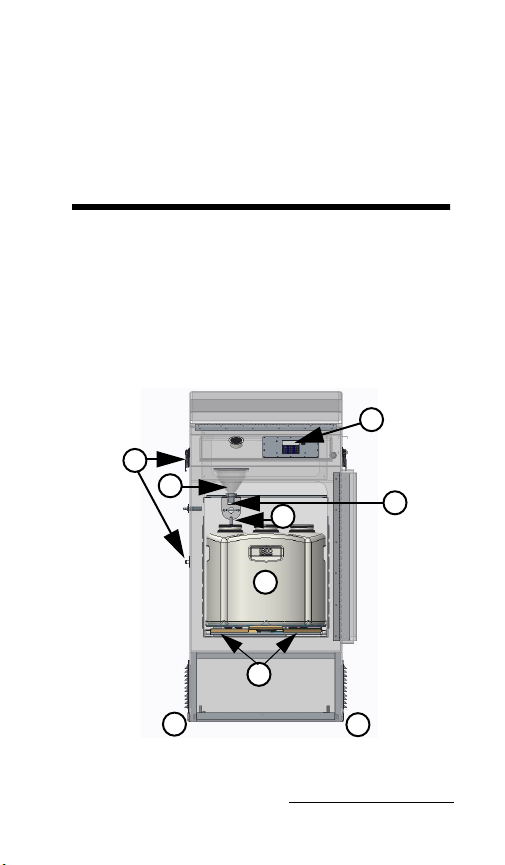
The sampler features are identified in Figures
1-1 through 1-4 and described in Table 1-1.
2
8
4
3
5
10
6
9
Figure 1-1 Sampler features (Front)
9
1-1
Platinum/Optima CVE Refrigerated Sampler
1
15
16
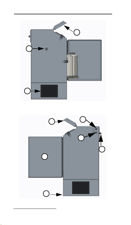
Figure 1-2 Sampler features (left side)
1
7
13
12
17
Figure 1-3 Sampler features (right)
1-2
14
Section 1 Introduction
14
18
11
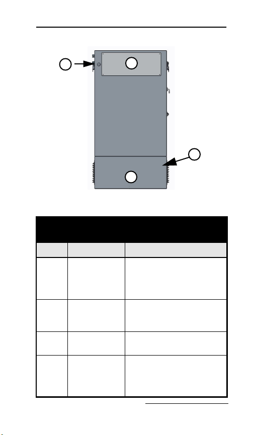
Figure 1-4 Sampler features (back)
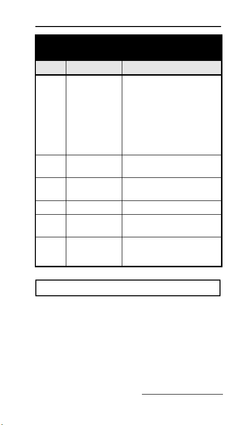
Table 1-1 Sampler Features
Item Name Description
1 Control
Panel Cover
2 Control
Panel
3 Discharge
Tube
4 Sample
Chamber
Protects the control panel
display and keypad. Can
be locked with user
supplied padlock.
Supports user control and
programming of sampler
operation.
Carries liquid to the
sample bottle.
Sample is measured and
collected in the chamber
then discharged into
sample container.
13
inside
1-3

Platinum/Optima CVE Refrigerated Sampler
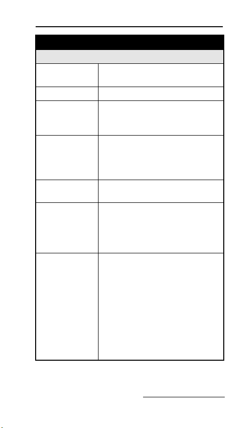
Table 1-1 Sampler Features
(Continued)
Item Name Description
5 Bottles Hold the collected
6 Sequential
Ta ble
7 Refrigerator
Door
8 Latch Secures the door. The
9Level
Adjustment
Feet
10 Liquid
Detector
11 Lower Back
Cover
12 External
Device
Connection
samples.
Rotates the bottles.
Protects the collected
samples inside the
refrigerated
compartment.
latch mechanism may be
locked with a
user-supplied padlock.
The sampler includes four
level adjustment feet, one
at each corner. Use these
to keep the sampler
leveled.
The liquid-sensing
electrodes detect fluid in
the sample chamber.
Access to Refrigeration
Module.
Supports connections to
external devices such as
a flow meter for sample
pacing or 4-20mA.
1-4
Section 1 Introduction
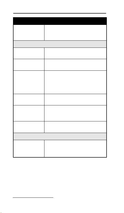
Table 1-1 Sampler Features
(Continued)
Item Name Description
13 Refrigeration
Module
14 AC Mains
Line Cord
15 Sample Line
intake
16 Air Vents Refrigeration air vents
17 Aux. Outputs Alarm, Fl. Star t, Fl.
18 Top Back
Cover
Modular,
corrosion-resistant
refrigeration assembly
cools the refrigerated
compartment to a
user-selected.
Temperature of 2 to 5 °C
(35 to 41°F).
Connects to AC power
source.
The sample intake line
connects here.
Start/Stop Run Status.
Access to the vacuum
pump, fuses, and
electrical components.
CAUTION
When lifting the sampler, cautiously lift with 2 people
(one on each side) with the door closed and latched.
Recommend using a lifting device.
1-5

Platinum/Optima CVE Refrigerated Sampler
1.2 Specifications
Table 1-2 Specifications
General
Size
(H×W×D):
Weight
(empty):
Bottle
Configuration:
Refrigerator
Body:
Powe r
Requirements:
Installation
Category:
Pollution
Degree:
Maximum
Altitude:
Humidity: 0 to 100%
Operational
Temperature:
49 x 25.5 x 25.5 inches
124.4 x 64.7 x 64.7 cm
97 kg
214 lbs.
6 configurations available:
24, 1-liter PP
12, 2.5-liter PP
4, 15-liter PP
1, 20-liter PE
1, 10-liter PE or glass
Molded fiberglass with UV
resistant gel coat.
115 VAC ±10%, 60 Hz
Running current 12 amperes
230 VAC ±10%, 50 Hz
Running current 6 amperes
II
3
2,000 meters
6,562 feet
–29 to 49 °C
–20 to 120 °F
1-6
Section 1 Introduction
Table 1-2 Specifications (Continued)
Tubing
Intake Suction
Tubing Length:
Material: Vinyl or PTFE-lined polyethylene
Inside
Diameter:
1to45m
3 to 150 feet
3
8 inch (9 mm)
1
2 inch (12mm)
Maximum
Suction Lift:
Typical
Repeatability:
Typical Line
Velocity at
Head Height:
115VAC/60Hz
28 ft. lift Pump
Typical Line
Velocity at
Head Height:
230 VAC/50Hz
28 ft. lift Pump
28 ft. (8.5 m) with38 inch suction
line
22 ft. (7.0 m) with ½ inch suction
line
±5 ml or ±5%
3
8 inch suction line
3ft: 9.84ft/s
10ft: 7.38ft/s
20ft: 4.50ft/s
3
8 inch (9 mm) suction line
1 m: 2.04 m/s (6.70 ft/s)
4 m: 2.10 m/s (6.89 ft/s)
7 m: 1.52 m/s (4.99 ft/s)
½ inch (12 mm) suction line
1 m: 1.74 m/s (5.71 ft/s)
3 m: 1.60 m/s (5.25 ft/s)
7 m: 1.33 m/s (4.36 ft/s)
1-7
Platinum/Optima CVE Refrigerated Sampler
Table 1-2 Specifications (Continued)
Liquid
Presence
Detector:
Controller
Enclosure
Rating:
Program
Memory:
Flow Meter
Signal Inputs:
Digital Alarms: 1 output, with 5 alarm
Number of
Composite
Samples:
Internal Clock
Accuracy:
Software
Sample
Frequency:
Wetted Liquid-sensor electrodes.
NEMA 4X
IP66
Non-volatile ROM (Flash)
Pulses (dry contacts)
4-20 mA
0-5 VDC
0-10 VDC
configurations
Programmable from 1 to 999
samples.
1 minute per month at 25 °C
1 to 9999 minutes, in 1-minute
increments
1 to 9,999 flow pulses
1-8

Section 1 Introduction
Table 1-2 Specifications (Continued)
Sampling
Modes:
Sample
Volumes:
Sample
Retries:
Rinse Cycles: Rinsing of suction line up to 4
Controller
Diagnostics:
Constant Time, Constant Volume
Variable Time, Constant Volume
Constant Flow, Constant Volume
Variable Flow, Constant Volume
Time and Flow Based Sampling
(refer to manual for more info)
Incremental Time per Bottle
Incremental Flow per Bottle
20 to 400 ml
If no sample reaches the
liquid-sensor electrodes, recycle
will activate up to 4 attempts.
rinses for each sample
collection.
Live diagnostics while sampling.
1-9

Platinum/Optima CVE Refrigerated Sampler
1-10

Platinum/Optima
CVE Refrigerated
Sampler
Section 2 Installation
2.1 Sampler Installation Overview
The following sections provide general
instructions for placing the sampler into
operation. In typical applications, the steps are:
1. Positing the sampler (Section 2.2)
2. Connecting power. (Section 2.3)
3. Installing a bottle kit. (Section 2.4)
4. Attaching the suction line. (Section 2.5)
5. Attaching a strainer. (Section 2.6)
6. Routing the suction line and strainer.
(Section 2.7)
7. Connecting the sampler to external devices.
(Section 2.8)
8. Configuring and programming the sampler.
(Section 2.9)
9. Locking the sampler. (Section 2.10)
2-1

Platinum/Optima CVE Refrigerated Sampler
2.2 Positioning the Sampler
There are a few considerations when selecting a
site for the sampler. The foremost concern
should be personal safety.
The installation and use of this product may
subject you to dangerous working conditions
that can cause you serious or fatal injuries.
Take any necessary precautions before entering
the work site. Install and operate this product
in accordance with all applicable safety and
health regulations, and local ordinances.
WARNING
If this product is used in a manner not specified
in this manual, the protection provided by the
equipment may be impaired.
WARNING
This product has not been approved for use in
hazardous locations as defined by the National
Electrical Code.
WARNING
The sampler is heavy. When lifting, use a
two-person lift from the right and left sides. When
possible, move the sampler using a two-wheeled
hand cart from the side. To prevent damage to the
refrigeration system, do not tip the sampler more
than 45°.
2-2

Section 2 Installation
Dangerous Locations – If you must enter a
manhole, confined space, or other dangerous
location to install the suction line and strainer,
observe standard safety precautions.
Support – The sampler should be installed on
a surface capable of safely supporting the
sampler, full liquid containers, and personnel.
AC Power – The mains line cord is the
disconnect device should you need to remove
power. Therefore, the electrical power outlet
should be accessible.
Environmental – The sampler is designed for
outdoor use. Refer to Table 1-2 for
environmental specifications. When possible,
avoid subjecting the sampler to chemical
attacks and direct sunlight.
Avoid Submersion – The sampler is rated
NEMA 4x (IP66), which does not protect from
submersion. In the event of submersion, liquid
entering the refrigeration system could
permanently damage the sampler; liquid
entering the bottle compartment could
contaminate the collected samples. Liquid
entering the electrical compartment for the
refrigeration system could result in a short
circuit and possible shock hazard.
Liquid Sample Collection Point – It is best
to keep the distance between the sampler pump
and the collection point as short as possible.
Also, the pump inlet should be located above
the liquid surface to be sampled with no liquid
traps. Gravity will aid suction line rinses and
allow the line to drain, thereby reducing the
2-3

Platinum/Optima CVE Refrigerated Sampler
possibility of sample cross-contamination. Refer
to Table 1-2 for maximum suction line lengths
and suction head heights.
Security – The sample compartment and
control panel have a padlock feature, but the
location may need additional security to
prevent tampering or vandalism.
Accessibility – The sampler must be installed
in a location where personnel can easily
exchange bottles and perform routine service.
The sampler requires about 2600 square
centimeters (925 in
2
) of floor space. Additional
space must be allowed in front of the sampler,
at its left and right sides, and above the
sampler. Do not block access to these areas.
Obstructions will make routine servicing
activities difficult or impossible.
The back of the sampler may be placed against
a wall. Allow free air flow on both right and left
sides of the sampler, particularly at the vents.
Unrestricted air flow behind and around the
sampler will allow the refrigeration system to
work efficiently.
Level Surface – The sampler should be placed
on a level surface and the feet on the
refrigerator body should be adjusted to prevent
tipping or spills. If the sampler is not level, the
sample liquid may miss the bottle mouth.
To level the sampler, place a bubble level on the
top of the refrigerated compartment.
2-4

Section 2 Installation
CAUTION
Do not tip the sampler on its side or back. Tipping
the sampler more than 45° might cause oil to run
into the compressor inlet, which can permanently
damage the refrigeration system.
2.3 Connecting Power
WARNING
Before connecting the sampler to an AC power
source, be familiar with the Electrical
Requirements listed at the front of the Installation
and Operation manual.
The factory assembles the sampler for either
115 VAC/60 Hz, or 230 VAC/50 Hz. The serial
number label located inside the control cover
identifies the AC power configuration of your
sampler. You cannot convert the sampler in the
field.
• The mains power cord for 115 VAC
samplers is equipped with a NEMA 5-15P
plug for standard North American
outlets.
• The mains power cord for 230 VAC
samplers is equipped with an EU 1-16P
plug for standard CEE 7-7 European
outlets.
• For other types of outlets that supply
compatible AC power, convert the mains
2-5

Platinum/Optima CVE Refrigerated Sampler
power cord plug with a locally-purchased
adapter.
Plug the mains power cord into the outlet. The
sampler control panel will briefly show this
start up display.
Note
The refrigeration system must sit for 24 hours before
powering up. This allows the compressor oil to drain
back into the compressor if the unit was tipped on its
side any time dur ing shipment or during installation.
2-6
Section 2 Installation
2.4 Installing a Bottle Kit
The sampler can hold 1, 4, 12, and 24 bottles.
Each of these bottle configurations are supplied
as a kit (see Table 2-1), which is normally
ordered with the sampler or when you desire to
change the bottle configuration.
Table 2-1 Bottle K its
Part Number Description
602320001 24-bottle Configuration. Includes
602320003 4-bottle Configuration. Includes
602320002 12-bottle Configuration. Includes
682320026 1-bottle Configuration. Includes
682320025 1-bottle Configuration. Includes
299001306 1-bottle Configuration. Includes
complete bottle rack with 24
polypropylene 1-liter wedge
shaped bottles with caps and
discharge tube.
bottle rack with 4 polypropylene
15-liter wedge shaped bottles
with caps.
complete bottle rack with 12
polyethylene 2.5-liter wedge
shaped bottles with caps and
discharge tube.
one polyethylene 3-gallon
(11-liter) container, lid, and full
bottle shutoff switch.
one polyethylene 5-gallon
(18.5-liter) container, lid, and full
bottle shutoff switch.
one polyethylene 5.5-gallon
(20.5-liter) round bottle and cap.
2-7

Platinum/Optima CVE Refrigerated Sampler
Refer to the instructions for your selected bottle
configuration:
•
Bottle Configuration: 24-1L – Section
2.4.1
• Bottle Configuration: 4-15L – Section
2.4.2
• Bottle Configuration:12-2.5L – Section
2.4.3
If you have selected a single (composite) bottle
kit, refer to the instructions in Section 2.4.4.
For first-time use of the sampler, or if you have
changed the bottle kit, be sure to configure the
program for the new bottle kit (Section 3.3.2).
Note
An incorrectly installed discharge tube can cause the
sample to miss the bottle. Do not try to manually rotate
the sequential table. This may damage the drive
system.
2-8

Section 2 Installation
2.4.1 24-1 Liter
The 24 bottle configurations use a rack to hold
and align the containers. To install the bottles
in the refrigerator using the rack:
1. Place the uncapped bottles into the rack.
Install bottle retaining ring and fasten with
the 3 bungee cords.
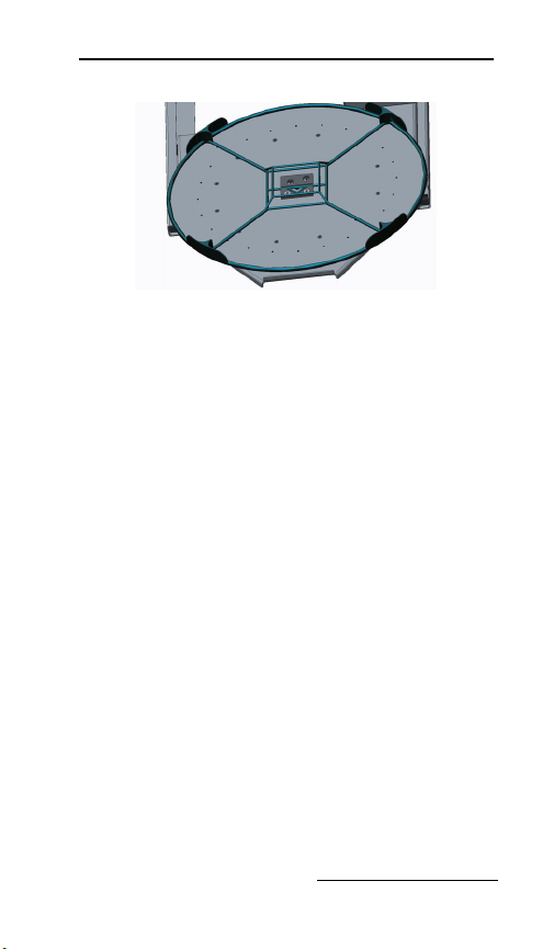
2. Pull the sequential table forward. (Platinum
only).
3. Locate the arrow in center of the rack and
align it with the center block located on the
turn table.
4. Roll the sequential table back into the
sampler. (Platinum only).
5. Activate the program to R
UN and the table
will turn to locate #Bottle 1. After the table
has stopped make sure the discharge tube is
centered on the bottle. If the discharge tube
is not centered, rotate/adjust the discharge
tube to the center of the bottle.
Note
Bottle caps can be stored in the center of the bottle
rack.
Figure 2-1 Bottle rack with 24-1 liter bottles
2-9

Platinum/Optima CVE Refrigerated Sampler
Note
Align the arrow in the center of the rack with center
block located on the table (Figure 2-2).
Figure 2-2 Locating center block
2.4.2 4-15 Liter
(Platinum only).
To install the rack and bottles:
1. Pull the sequential table forward.
2. Place the four bottles on the sequential
table using the alignment rack to position
the bottles. Remove the bottle caps.
3. To load or unload the sample bottles there is
a table jog feature. When the program is not
in the run mode, the jog feature is available
by pushing the 0 button on the keypad. The
table will jog 90° each time 0 is pushed.
4. When the bottles are loaded, slide the
sequential table back into place.
2-10
Section 2 Installation
Figure 2-3 The 4-15 liter bottle rack
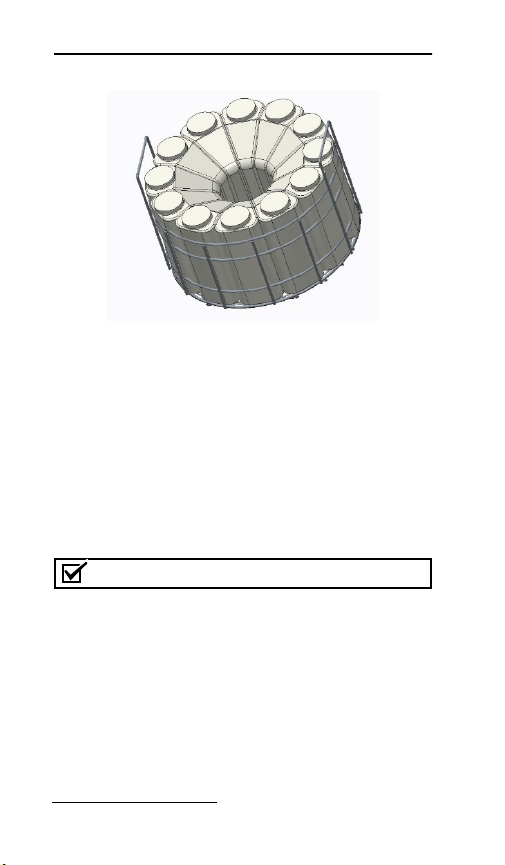
2.4.3 12-2.5 Liter
The 12 bottle configuration uses a rack to hold
and align the bottles. To install the bottles into
the sampler:
1. Place the uncapped bottles into the rack.
2. Roll the sequential drive out.
3. Locate the arrow in the center of the rack
and align it with the center block located at
the center of the drive table.
4. Roll the sequential table back into the
refrigerated compartment.
5. Activate the program to R
UN and the table
will turn to locate #Bottle 1. After the table
has stopped make sure the discharge tube is
centered in the bottle. If the discharge tube
is not centered, rotate/adjust the tube to the
center of the bottle.
2-11
Platinum/Optima CVE Refrigerated Sampler
Figure 2-4 Bottle rack and 12-2.5 liter
2.4.4 Single Bottle Configuration
If your sampler is configured for composite
sampling simply place the discharge tube in the
center of the sample bottle.
Composite Bottle Installation
1. Install the discharge tube (if needed).
Remove bottle cap and position the bottle
under the discharge tube.
Note
Make sure the discharge does not contact the bottle in
any way.
2. Go to BOTTLE OPt. in the menu and select
OMPOSITE and then select your bottle size.
C
2-12

Section 2 Installation
Figure 2-5 One 20 Liter PE Bottle
2.5 Attaching the Suction Line
Note
The suction line is the tubing from the sampling point to
the sampler intake fitting. The sampler typically uses a
3
/8inch ID (9 mm) suction line of lengths from 3 to 150
feet. Teledyne ISCO offers vinyl or PTFE-lined suction
lines. The PTFE-lined tubing has a polyethylene jacket
to protect it from kinks and abrasions.The vinyl suction
line contains a very low parts-per-million level of
phenols. If phenol content affects your sample analysis,
use the PTFE-lined suction line.
2-13

Platinum/Optima CVE Refrigerated Sampler
Teledyne ISCO ships suction line in standard
lengths of 3.0 m (10 ft) or 7.6 m (25 ft). Either
length should be cut to the shortest length
feasible for the installation. When installed, the
line should run the shortest possible distance
from the collection point to the sampler,
preferably with a gradual upward slope. Excess
suction line should be cut, not coiled. Coiled
suction line will hold liquid between sample
events which could cross-contaminate samples
or freeze in cold climates. If the standard
lengths are too short, or if you are cutting
3
compatible
/8inch ID suction line from a bulk
spool, you can use lengths up to 45 m (150 ft).
2.5.1 Vinyl Suction Line
The sampler inlet fitting is on the left side of
the samplers.
fittings are available to choose from. The
sample line is
3
/4” clear PVC tubing which is connected to the
1
/2” and3/8” stainless steel barbed
3
/8”x5/8” (I.D. x O.D.) or1/2” and
a right-angle barbed fitting.
Figure 2-6 Left side of the sampler
2-14

Section 2 Installation
2.5.2 PTFE-lined Suction Line
Inserting a tube coupler into PTFE-lined
suction line will damage the thin lining.
Instead, refer to Figure 2-7 and the instructions
below to attach PTFE-lined suction line to the
sample tube:
1. Slide a short piece of silicone tubing over
the inlet fitting and install a hose clamp (B).
2. Push about 20 mm of the PTFE-lined
suction line into the end of the silicone tube
(A).
3. Slide the clamp over the union and tighten.
Do not overtighten; this might cause the
tubing to collapse or restrict the flow.
A
B
Figure 2-7 Connecting PTFE-lined suction
line (A) silicone tube (B)
2-15

Platinum/Optima CVE Refrigerated Sampler
2.6 Attaching a Strainer
To select the right strainer for your application,
refer to Figure 2-8 and the table that follows.
øA
Low Flow
Weighted
60-9004-367
69-2903-138
CPVC
60-3704-066
øB
C
Figure 2-8 Strainers
To attach the strainer to the suction line,
carefully screw the strainer’s threaded
connector into the suction line. If attaching the
strainer to an PTFE-lined suction line, heat the
suction line end before threading the strainer
2-16

Section 2 Installation
into the line. Warming PTFE-lined tubing will
make it more pliable to avoid damage.
2.6.1 Alternative to Strainers
When sampling from high velocity streams
with heavy suspended solids, some field
investigations suggest that more
representative samples are obtained without
the strainer. Consider attaching a short piece of
thin walled aluminum tubing to the end of the
suction line; anchor the tubing so that the inlet
opens upstream. The aluminum tubing’s thin
wall will not disturb the flow stream, and most
sample analyses disregard aluminum ions.
Under most conditions, a pre-sample line rinse
removes any debris over the tubing entrance.
2.6.2 Max Unanchored Length
During a pre or post-sample purge or line rinse,
the suction line is filled with air which might
cause the suction line and strainer to float. If
the length of the suction line and strainer
exceeds the listed value, securely anchor the
strainer.
Even if the maximum length is not exceeded, it
is a good idea to anchor the suction line and
strainer when sampling from high velocity or
turbulent flow streams.
2-17

Platinum/Optima CVE Refrigerated Sampler
2.7 Routing Suction Line and Strainer
Route the suction line so that it has a
continuous slope from the liquid source to the
sampler. This helps to drain the line during pre
and post-sample line purges and rinses. If a
suction line exposed to freezing climates does
not fully drain, there is a risk of liquid in the
suction line becoming frozen. Frozen liquid will
cause the sample collection to fail. A warm
sampling source can usually prevent this,
provided there are no traps or low spots in the
suction line. Some extreme situations may
require more protective measures, such as
insulating the suction line or applying heat
tape or adding a pump heater.
For representative samples, place the strainer
in the main current of the flow stream, not in
an eddy or at the edge of flow. Placing a strainer
at the bottom may produce samples with excess
heavy solids and no floating materials, while
placing it at the top may produce the opposite
conditions.
2-18

Section 2 Installation
2.8 External Devices
You can connect the sampler to an external
instrument (Figure 2-9) for a variety of reasons.
Typical reasons include:
• Receiving flow pulses from a flow meter
device for variable time.
Figure 2-9 External device connections are
located on the upper right side of the sampler
• Receiving an enable pin signal to enable
sampler operation once site conditions
warrant sample collection.
• Receiving a linear 4-20 mA analog or
pulse representation of the flow rate for
variable time.
• Sending alarm signals when sampling
events occur.
2-19

Platinum/Optima CVE Refrigerated Sampler
These types of connections can be categorized
as Standard ISCO device connections or other
device connections. Each type is discussed in
Sections 2.8.1.
2.8.1 Other Device Connections
You can connect the sampler to receive a
4-20 mA signal, 0-5 VDC, 0-10 VDC or pulses
from an external device.
CAUTION
Risk of equipment damage. Only experienced
electronic technicians should make the connections
to an external device.
To connect the external device, refer to Table
and select the appropriate pins. Connect the
2-2
wires by inserting the wires into the proper pin
number and tightening them. To complete the
connection, be sure to finish the connector
assembly.
Analog Flow Signal
(4 pin connector)
34
12
Pin 3+
Pin 4Pulses (Dry Contacts)
Pin 1
Pin 2
2-20

Section 2 Installation
(7 pin connector)
1
2
1&2 Float
Start-Orange
3&4 Run Status-Blue
6
3
5&6 Alarm-Red
45
Table 2-2 Input Connector (4 pin)
Pin Input
Signal
1 Pulses Dry
2 Pulses Dry
Signal
Name
Contact
Contact
Parameters/
Comments
Pulse input
Pulse input
2-21

Platinum/Optima CVE Refrigerated Sampler
Table 2-2 Input Connector (4 pin)
Pin Input
Signal
3 4-20
mA,0-5VD,010VDC
(+)
4 4-20
mA,0-5VDC,
0-10VDC
(-)
Signal
Name
Analog
Analog Input: Linear current
Parameters/
Comments
loop signal
representing
minimum flow rate at
4 mA, maximum flow
rate at 20 mA
(0-5VDC) 0-Minimum
(0-10VDC)
0-Minimum
10-Maximum
5-Maximum
2-22

Section 2 Installation
Table 2-3 I/O Connector (7 pin)
Pin Wire
Color
1 Orange Float Start
2 Orange Float Start
3 Blue Run
4 Blue Run
5 Red Alarm Dry contact
6 Red Alarm
Signal
Name
or
Float
Start/Stop
or
Start/Stop
Status
Status
Parameters/
Comments
Dry contact
Closed contact to
initialize program start
or close contact to start
program and open
stops program
Dry contact
Relay 250V 5 amp
rated, closed contact
during sample cycle
Relay 250V 5 amp
rated, closed contact
during a fault condition
or program done
2-23

Platinum/Optima CVE Refrigerated Sampler
2.9 Configure and Program the Sampler
To complete the installation, the sampler
software should be configured and
programmed. Refer to Section 3 for
programming instructions or Section 2.11 for
the quick start guide.
Configure the sampler to make sure that it
recognizes what bottle configuration is
installed. Program the sampler to specify how
and when the sampler should collect liquid
samples.
2.10 Locking the Sampler
Locking the sampler is an optional step that
can prevent tampering with the sampler
operation or collected samples.
To prevent tampering with the sampler
operation, the sampler has a P
When enabled, this software feature requires a
numeric password to access most of the control
panel functions. Refer to Section 3.3.9 to enable
this option.
To prevent tampering with the collected
samples, place a padlock on the refrigerator
door latch and control panel.
ROGRAM LOCK.
2-24

Section 2 Installation
2.11 Quick Start Guide
2.11.1 Program Ready Screen
At initial power up, the controller displays the
ROGRAM READY screen:
P
To run the displayed program, select F1 for
UN. Program timer begins and the program
R
runs as specified.
• Select F1 to S
point of the program running mode.
• Select F1 again to R
and go back to the P
To configure the program settings, select F3 for
ENU. Use the arrows to the right of the
M
display to scroll through the programs (1-6).
Press F3, or S
configure.
• Optionally scroll through the P
CONFIGURATION (PGM CONFIG) menu
using the arrow keys to select which
program setting to configure. The
following list displays all of the variable
sub-settings within each program
setting.
TOP the program at any
ESET the program
GM READY screen.
EL to select the program to
ROGRAM
2.11.2 Program Configuration
Cycle: Set the sampling parameters here.
Prepurge: Enter the number of seconds (0-99)
for the system to purge the intake lines prior to
sampling. Then press F3 to accept.
2-25

Platinum/Optima CVE Refrigerated Sampler
Sample Seconds: The sample size is set with
the adjustable intake tube. Set a sampling time
duration that is long enough to allow time for
the sample to fill the sample chamber and
touch the liquid sensing electrodes. Test this
and increase the time if no sample enters the
chamber. Press F3 to accept
.
Postpurge: Enter the number of seconds
(10-99) for the system to purge the intake after
the sample is taken. Press F3 to accept.
Num Rinses: Enter the number of times (0-4)
the intake line should be rinsed, prior to each
sample. Press F3 to accept. This option is to
precondition the sample line before taking a
sample.
Pressure Time: This menu item displays only
if the Number of Rinses is not zero. Type in the
number of seconds (0-99) each rinse should
pressurize the sampler chamber.
Vacuum Time: Enter the number of seconds
(0-99) each rinse should generate suction. The
time should be short enough that the sample
does not enter the sample chamber during the
rinse. Press F3 to accept.
Recycle: Use up and down arrows to enable or
disable the sample retry feature, or press F3 to
accept the setting. When the recycle feature is
enabled, the sampler makes a second attempt
to take the sample, if it failed to collect a
sample on the first try.
Consecutive SMPL: To draw just one sample
per interval, type 1 and press F3 to accept.
2-26

Section 2 Installation
2.11.3 Sample Interval
SMPL. Interval: Press F3 to select the
AMPLING INTERVAL setting. Use the up and
S
down arrows to scroll through the options and
select F3 to accept. Generally, the sampling
interval is a set time, in between samples.
2.11.4 Time Option
Use the up or down arrow keys to scroll to the
desired option (e.g. Time Fixed). Press F3 to
accept.
SMPL Min: Use the keypad to enter the
desired S
AMPLING TIME INTERVAL or leave as is,
then press F3 to accept.
2.11.5 Bottle Options
Sample Type: Use arrows to scroll and press
F3 to select C
ISCRETE/SEQUENTIAL SAMPLING type.
D
•IfD
the next menu is B
OMPOSITE or
ISCRETE SAMPLE TYPE was selected,
OTTLE CONFIG. Use
the arrows to scroll to the desired bottle
configuration that is installed in the
sampler, then press F3 to select.
Num. Bottles: Enter the number of bottles
that you want to use, otherwise press F3 to
accept the default setting to use all the bottles.
SAMPLS/Bottle: Enter the number of samples
that you want to collect in every bottle. Then
press F3 to accept this setting. Be sure to not
overfill the sample bottles.
2-27

Platinum/Optima CVE Refrigerated Sampler
Index Type: Use the arrows to scroll to the
desired indexing type. The A
FTER BOTTLE
setting is defaulted, which tells the program to
rotate to the next bottle, once all of the specified
samples are discharged into the current bottle.
Press F3 to accept this setting.
After entering these settings, the screen will
return to the P
GM CONFIG menu, indicating
that the program setup is complete. If you do
not wish to enable any P
ROGRAM RUN OPTIONS
(see manual for more detail), press F1 twice to
return to the P
ROGRAM READY screen.
2-28

Platinum/Optima
CVE Refrigerated
Sampler
Section 3 Programming
3.1 Control Panel Description
Figure 3-1 Control Panel
3-1

Platinum/Optima CVE Refrigerated Sampler
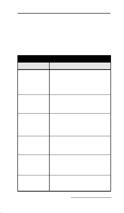
Table 3-1 Control Buttons
Icon Name Description
F1 HOME
F2 MAN
F3
Back Press this button to back
Enter Press this button to back
0-9 Keypad Keypad enter numbers
RUN
STOP
RESET
ESC
YES
TIMED
GRAB
BACK
MORE
MENU
SEL
PAUSE
RESTART
START
DETAIL
CONTINUE
NO
Go to home screen
Start the program
Stop the program
Reset the program
Go back to previous menu
Accept
Manual sample
Set a timed delay
Grab sample
Go back in the program
See more detail in log file
Go to menu
Select
Pause the program
Restart a program
Initiate sample
View log detail
Continue program
Reject
one space when entering
a number.
one space when entering
a number.
3-2

Section 3 Programming
3.2 Getting Started
Apply power to the sampler (see Section 2.8).
The start-up screens appear on the LCD
display.
Note
The refrigeration system may need to sit 24 hours
before star ting if the unit was tipped upside down during
shipment or installation. This will allow the oil in the
compressor to drain back.
After installing the sampler plug the power
cord into the proper receptacle. The display will
light up and programming can begin. The
program is ready to be configured.
Pgm 1: Ready: This screen displays three
menu options appear R
UN TIMED MENU.
If you have just installed the sampler, you will
first need to program the sampler (Section 3.5).
To program the sampler:
3-3

Platinum/Optima CVE Refrigerated Sampler
1. Pushing F3 located under MENU will
advance the program to M
2. Go to P
3. Press S
ROGRAM menu. Pushing F3 the menu
advances to P
GM SELECT PROGRAM 1).
ELECT to enter the PGM SELECT
AIN MENU.
menu.
This part of the menu will allow you to make
changes to the program.
• Cycle (Sampling settings)
• Smpl. Interval (Timed or Flow intervals)
• Bottles Opts. (Composite or Discrete)
• Pgm. Run Opts. (Run Options)
• Pgm. Events (Scheduled Events)
3.3 Configuring the Sampler
Before operating the sampler, configure the
sampler software. Doing so will set the time
and date, allow the sampler controller to
correctly use the hardware.
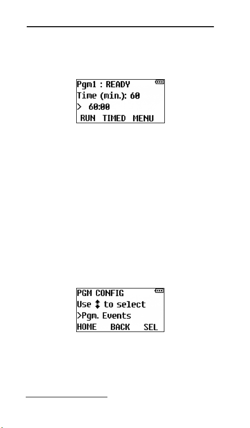
To begin from P
1. Press the Menu(F3) button, the screen will
advance to M
press SEL(F3).
2. The next screen is P
#1 push SEL(F3) the screen advances to PGM
CONFIG >CYCLE. In this configuration you
set the parameters.
GM1: READY
AIN MENU >PROGRAM MENU
GM SELECT >PROGRAM
You can step through the parameters using the
EL(F3) button. If a change was made to the
S
3-4

Section 3 Programming
program push SEL(F3) to enter the change or to
scroll thru the settings.
To return to the P
OME(F1) two or three times depending where
H
GM1: READY screen, push
you are in the program.
3.3.1 Set Clock
To set the clock:
1. Scroll to A
scroll until you see >S
F3(S
DMIN.MENU push SEL(F3) and
ET DST and push
EL). Use the up and down arrow to
scroll winter/summer.
2. Then push S
EL(F3) to select.
Setting the time and date allow the sampler
controller to correctly use the hardware. There
is an option to set the time for daylight saving
time (winter or summer).
3-5

Platinum/Optima CVE Refrigerated Sampler
Press the number buttons to type the current
date and hours (using 24-hour format). Press
NTER to accept the date and move to time.
E
When finished the screen will advance to
DJUST LCD screen.
A
3.3.2 Bottle Configuration
Select this option to specify the installed bottle
configuration (Section 2.3). The sampler uses
this setting to determine available bottle
options and control the operation of the
indexing table.
1.
3-6

Section 3 Programming
To select the bottle configuration press ENTER
or SEL(F3).
2.
To select C
up or down arrow and push S
OMPOSITE or DISCRETE sampling use
EL(F3).
Composite
Discrete
hen the bottle and sample size is set, make
W
sure not to overfill the bottles.
3.3.3 Suction Line
The intake tubing length is not entered into the
program. The sample time is set long enough
for the sample chamber to fill and the liquid to
touch the liquid sensor.
3-7

Platinum/Optima CVE Refrigerated Sampler
3.3.4 Rinse Cycle
You can use RINSE CYCLES to condition the
suction line and strainer before collecting a
sample. R
INSE CYCLES may also improve
sample volume repeatability by ensuring the
suction line is wetted before each sample.
The rinse setting is located in the C
YCLE MENU
after post purge. The maximum rinse cycles
and recycles is 4.
• 0 turns the Rinse cycle option
OFF.
• 1-4 Number of Rinses activates the
option:
• Enter RINSE VACUUM time. Be sure that
the vacuum cycle does not allow the fluid
to pump into the sample chamber. Test
and adjust the vacuum time as necessary.
3-8

Section 3 Programming
• Enter RINSE PRESSURE time. Pressure
time should be at minimum the entered
vacuum time.
WARNING
During the rinse cycle if the sample enters the
sample chamber and reaches the liquid-sensor
electrodes, the program will stop the vacuum time
and switch to purge.
3.3.5 Liquid Detector and Recycle
The liquid sensor electrodes are mounted at the
top of the sample chamber lid. If the sample
does not touch the electrodes, then S
FAILED will appear and RECYCLED will activate
if programmed.The liquid detection feature is
always on. The R
located in the C
INSE and RECYCLE option is
YCLE MENU after post purge.
The maximum number of rinse and recycle
cycles is four.
AMPLE
Turn recycle on or off
using the arrow keys
3-9
Platinum/Optima CVE Refrigerated Sampler
ON: If the sampler fails to detect liquid, it will
try again up 4 times to collect the sample.
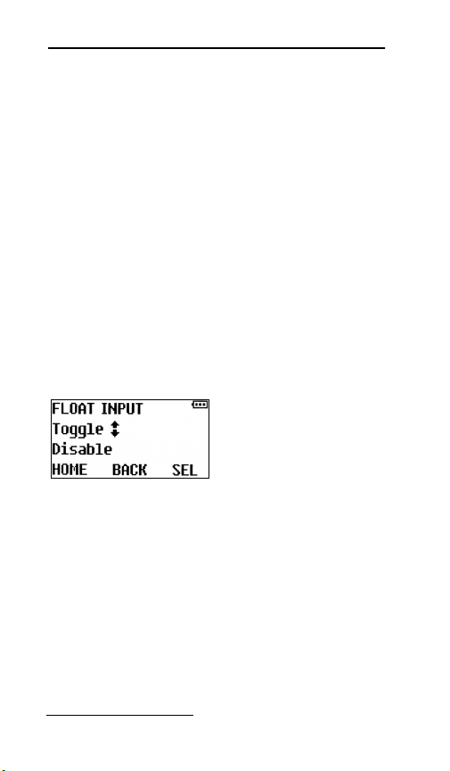
3.3.6 Float Input
Depending if the FLOAT INPUT options have
been factory-configured, enabling this input
will configure the sampling program to delay
sample collection until that circuit closes and
subsequently either:
• Float Start: continue sampling even if
the float circuit reopens,
• Float Start/Stop: toggle the collection of
samples on and off as the rising and
falling stream level closes and opens that
circuit. This feature may be used with
full bottle shut off for composite samples.
Toggle to change
Disable/ Enable
and press Enter.
If Disable the option
is turned off.
The sampler controller is D
ISABLED when pins
1 and 2 are open of the external 7 pin connector
(orange wires). The controller is E
NABLED when
pins 1 and 2 are closed.
3.3.7 Output Pins
An alarm output is based one of the following
events:
• Program Done: This event occurs when
a running sampling program has finished
3-10

Section 3 Programming
or full bottle. This alarm output stays on
as long as the run time display reads
PGM: DONE.
• Recycle: The collection of incomplete
samples by repeating the sampling cycle
as many as four times. To enable or
disable it.
• Temperature Error: The temperature
has been above its set temperature for
more than 30 minutes.
• Failed Sample: This event occurs when
the sampler failed to reach the
liquid-sensor electrodes. This may occur
if the intake line is plugged or the
vacuum time may need to be increased.
• Indexing Error: This event occurs when
the turntable has an indexing failure.
This condition must be corrected before
the sampling program can resume. This
alarm output stays on until the condition
is corrected.
(Alarm- 7 pin output connector using 2 red
wires pins5&6.)
• Run Status: This event occurs each time
a sample is taken. The output stays on
until the sample event is completed.
(2 blue wires pins 3&4)
• Float Start or Float Start/Stop:
*Float Start- If the FLT S
TART setting is
selected, the program will start with a
closed contact and the program will continue
3-11

Platinum/Optima CVE Refrigerated Sampler
sampling without interruption even if that
circuit reopens.
*Float Start/Stop- If the FLT S
TART/STOP
setting is selected, the program will reset its
sampling interval counters and not restart
them until the float circuit closes again (i.e.,
those counters will restart from zero when
the water level rises high enough to close
the float switch).
Note
The full bottle switch uses the float start/stop feature. If
float start or start/stop is being used as a remote start
the full bottle switch cannot be used.
3.3.8 Refrigeration
The sampler will display the interior cabinet
temperature. Scroll thru the run displays to
locate the temperature.
Setting the Refrigerator Temperature: The
thermostat is located on the lower right side of
the refrigeration module. Remove the air vent
to adjust the temperature by using the up and
down arrow on the display. To set the
temperature output 1 for refrigeration and
output 2 for the heater.
3-12

Section 3 Programming
3.3.9 Program Lock
Select this option to turn the PROGRAM LOCK
feature on or off, and to change the password.
When this security feature is enabled, the
sampler requires a numeric password before a
user can configure the program.
The program protection is
password is set to zero.
OFF when the
3-13

Platinum/Optima CVE Refrigerated Sampler
WARNING
DO NOT FORGET THE PASSWORD!
Should you forget the password, contact ISCO’s
Customer Service department for assistance.
3.3.10 Language Selection
Select this option to change the display
language.
1.
Press S
2.
3-14
EL(F3) or ENTER

Section 3 Programming
Scroll using the up and down arrow to select a
language (English, German, French, Spanish,
Italian, Polish, Danish, Swedish).
Press SEL (F3) or ENTER.
3.
If the language is correct at the top of the
screen press Y
ES, if it is wrong press NO.IfNO
was selected the language did not change.
3.3.11 Set Unit ID
Each sampler can be assigned a unique ID
number that will be included in its archival data
files.
Press SEL(F3)
3-15

Platinum/Optima CVE Refrigerated Sampler
3.3.12 Diagnostics
Each time a sample is taken, the program
checks the bottle location when in the
sequential sampling mode.
3.3.13 Exit Configuration
Pressing HOME (F1) the program will exit the
ROGRAM menu and return to PGM: READY.
P
Depending on what part of the P
ROGRAM menu
you are in it may take 2 or 3 times to exit the
ROGRAM menu completely.
P
3.4 Sampling Program Overview
The sampling program controls how often
sample events occur and what should take
place at each event. A sample event may
happen when:
• Starting a flow paced program that is
programmed to sample after a delay
(Section 3.5.13).
• A time paced program reaches the first
sample time and date.
• The programmed time interval has
elapsed.
• The programmed number of flow pulses
has been reached.
At each event, the sampler:
1. Resets the programmed flow or time pacing
interval after initializing a sample.
2. Purges the suction line (see Section 3.3.3).
3-16

Section 3 Programming
3. Sends a closed contact while sample is
taken. The sampler deposits the
programmed sample volume into the bottle.
If programmed to deposit a sample volume
in more than one bottle, the sampler:
a. Moves the table to the next bottle.
b. Deposits the programmed sample
volume into the bottle.
c. Repeats steps 3a and 3b until the
programmed number of bottles per event
is reached.
4. Purges the suction line (see Section 3.3.3
).
There are five categories of sampling program
instructions that control the above actions in an
event. These categories include:
• Cycle: Parameters that configure the
sampling cycle, purge, sample time, post
purge, rinse, recycle, and consecutive
samples.
• Sample Interval: Define what controls
the sample collection interval based on
Time or Flow.
• Bottle Option: Define which sampling
type (discrete/composite) and the bottle
configuration.
• PGM Run Options: Configure program
run options including auto rerun, delay
start, float, fault, timed stop, and bottle
limit.
3-17

Platinum/Optima CVE Refrigerated Sampler
• Program Events: Configure scheduled
events that start, stop, pause, halt, and
resume the program.
3.4.1 Program Configuration
The following are the Program setup categories
and their related programming screens:
Press F3/SEL
to advance
Press F3/SEL
to advance
3.4.2 Sampling Cycle
Press F3/SEL
3-18
Press F3/SEL

If Rinse is 0 program
advances to Recycle
Section 3 Programming
Press F3/SEL
Press F3/SEL
Press F3/SEL
3-19

Platinum/Optima CVE Refrigerated Sampler
Press F3/SEL
Press F3/SEL
Press F3/SEL
Press F3/SEL
3-20

3.4.3 Sample Interval
Section 3 Programming
Or
Press F3 (SEL) to enter the programmed
value and to advance to the next screen
3-21

Platinum/Optima CVE Refrigerated Sampler
3.4.4 Bottle Configuration
Press F3/SEL
3-22

Section 3 Programming
The INDEX TYPE can be configured to rotate to
the next bottle using the following indexing
criteria:
FTER BOTTLE- The table will advance
•A
after the bottle is serviced. If each bottle
was to receive 3 samples per bottle the
table would advance after the 3
rd
sample
in each bottle.
FTER SAMPLE- The table advances after
•A
each sample. If the program was for 2
samples per bottle and turn after the
sample, the table would make two full
revolutions.
FTER TIME- The turntable rotates each
•A
time a specified indexing interval
elapses.
EAL TIME- The turntable rotates at a
•R
fixed duration intervals stating at a
specified time of day.
3-23

Platinum/Optima CVE Refrigerated Sampler
3.4.5 Program Run Options
Press F3/SEL
•AUTO RERUN-If you configure a Start
Event to repeatedly start and stop the
sampler, enabling the Automatic Rerun
parameter will allow the program to
restart without having to reset.
AULT OPTION- Enable turns the Fault
•F
ON. The alarm condition displays
Option
the Alarm Icons, and also energizes a
relay, if a fault condition is detected.
EMPERATURE OPTION - If the Fault Option
-T
is Enabled, the Temperature Fault option is
displayed. This feature enables an alarm
when the enclosure temperature is out of
spec for more than 30 minutes. Toggle
between Enable or Disable.
3-24

Section 3 Programming
•DELAYED START- The program start time
can be delayed in minutes.
FLOAT INPUT- Enable turns the Float
•
ON. Refer to the manual for more
option
details.
•TIMED STOP- This parameter configures
the program to automatically stop a
specified number of hours or minutes
after program start. Select: None, 24
Hour, 12 Hour, 8 Hour or Custom.
3-25

Platinum/Optima CVE Refrigerated Sampler
•BOTTLE LIMIT:
-Program Stop: after discharging a specific
number of samples into a container the program stops and will have to be reset.
-Program Continue: the program will
draw samples indefinitely. You must replace
bottles as the program runs, to avoid bottle
overfill.
3-26

Section 3 Programming
3.4.6 Program Events
Each program’s scheduled events are defined by
a list that can be accessed via the P
ROGRAM
EVENTS group. Each event on that list has three
associated values:
• The type of event (start, stop, pause, halt,
resume or manually sample).
• The days of the week on which the event
will be executed.
3-27

Platinum/Optima CVE Refrigerated Sampler
• The time of day on those days at which
the event will be initiated.
Select the “End List” event when you have
programmed all the desired program events.
You can remove events by disabling the event
for each day of the week.
3.5 Programming Steps
To begin programming from the PGM READY
screen, use the menu F3 (SEL) button to select
ROGRAM. Press the F3 button to display the
P
first programming screen P
3.5.1 Sample Pacing
There are two pacing methods for sampling
programs, Time Paced and Flow Paced.
• Time Paced sampling programs use the
sampler’s internal clock to collect
samples at a constant time or variable
time interval. When you program the
sampler for time pacing, the sampler will
prompt you to enter the time between
sample events in minutes.
• Flow Paced sampling programs require
an electronic signal from a flow
measurement device. This electronic
signal is typically a dry contact (pulse)
that indicates some user-programmed
volume interval has passed through the
flow channel. Because each pulse
represents a volume interval, flow pacing
rates are proportional to the volume of
ROGRAM #1.
3-28

Section 3 Programming
water flowing through the channel. This
is sometimes called “Constant Volume
Variable Time (CVVT) sampling.” When
you program the sampler for flow pacing,
the sampler will prompt you to enter the
number of pulses to count before
collecting a sample.
All Teledyne ISCO flow meters provide a
compatible flow pulse. Non-ISCO flow
measurement devices may be used to paced the
sampler. Refer to Section 2.8– External Devices
for more details.
Use the F3(S
flow option, then press the E
EL) button to select the time or
NTER button.
3.5.2 Time Paced
Time Paced Only – Use the number buttons to
enter the time interval in minutes. The sampler
collects a sample each time this interval elapses
while the program is running.
3.5.3 Flow Paced
Flow Paced Only – Use the number buttons to
enter the flow interval as a number of pulses.
While the program is running the sampler
counts the flow pulses until this number is
reached. At this time the sampler collects a
sample and resets the interval to begin
counting again.
The volume that each flow pulse represents is a
fixed volume. Refer to the instruction manual of
the flow measurement device.
3-29

Platinum/Optima CVE Refrigerated Sampler
For example, consider an ISCO 4250 Flow
Meter programmed to send a flow pulse every
100 gallons. If you are required to collect a
sample every 10,000 gallons, you would enter
100 flow pulses. 10,000 gallons 100 gallons =
100 pulses.
If the flow measurement device sends flow rate
data via a 4-20 mA current loop instead of flow
pulses. The sample program needs to be
changed in the SMPL. I
NTERVAL menu. The
sampler assumes that the current is linear
from 4 mA at zero flow to 20 mA at the
full-scale flow rate.
1. Select the flow input type to 4-20mA.
2. Enter the maximum flow rate (MAX. LPM).
3. Enter the liters between each sample
(SMPL
LITERS).
Example: Consider a flow meter output to 20
mA at 1,000 liters per minute, the peak flow
rate of the channel. If you are required to collect
a sample every 5,000 liters, you would enter
5,000 in the SMPL. L
ITERS menu. The sampler
would totalize the flow base on the MAX LPM
and the flow signal. The sampler will totalize
the liters based on the flow signal. There are no
flow calculations needed, the sampler does that
for you.
3.5.4 Bottles per SampleEvent
Multiple Bottles Only – The sampler places a
sample volume in one bottle or sets of bottles at
each sample event. Use this screen to enter the
3-30

Section 3 Programming
number of bottles to repeat the sample volume
at each sample event. The effect of this number
is illustrated below.
Distribution scheme with
one bottle per sample event.
Samples events are
numbered.
Distribution scheme with
two bottles per sample
event.
Distribution scheme with
three bottles per sample
event.
3.5.5 Switch on Time Indexing
Multiple Bottles Only – The sampler can
switch bottles at regular time intervals. Use
timed indexing to switch Bottles/Sets based on
time.
Multiple Bottles Only – If you selected
Switch on Time, use the number buttons to
enter the desired time interval for bottle set
switches.
3.5.6 Real Time Indexing
Flow Paced, Multiple Bottles Only–If you
are switching bottles by time intervals, use this
3-31

Platinum/Optima CVE Refrigerated Sampler
screen to specify the first switch time. All other
bottle or bottle set switches will be relative to
this time. Press the number buttons to enter
the time of day in 24-hour format.
3.5.7 Samples Per Bottle
Multiple Bottles Only – The sampler places a
sample volume from one or more sample events
in a bottle. Use this screen to enter the number
of samples to be placed in a bottle. The
following diagrams illustrate the effect of this
number.
Distribution scheme with
one sample per bottle
Sample events are
numbered.
Distribution scheme with
two samples per bottle.
Distribution scheme with
three samples per bottle
This SAMPLES PER BOTTLE feature can be
combined with the BOTTLES PER SAMPLE
EVENT (Section 3.5.4) to build more complex
distribution schemes, sometimes known as
3-32

Section 3 Programming
multiple bottle compositing. The following
illustrates this example:
Distribution scheme with
three bottles per sample
event and three samples
.
per bottle. Sample events
are numbered
3.5.8 RunContinuously
Sample programs can run indefinitely or stop
by going to P
GM RUN OPTS and then to BOTTLE
LIMIT. Select PGM.CONTINUE to run the
program continuously or P
GM STOP to stop the
program when complete. Continuous sampling
resets the distribution when the distribution
sequence is complete. That is, when the last
bottle/set is reached, the next bottle/set is the
first bottle/set.
In this mode, the sampler assumes that any
filled bottles are replaced and ready to receive
samples while the program is running, thus the
pacing interval is never interrupted.
If you select PGM S
TOP, the sampler will run
until it completes the distribution sequence, at
which time it stops the program and reports
ROGRAM DONE. The sampler will wait in this
P
state until the bottles have been emptied and
the program is restarted.
If your sampler is configured for composite
sampling, refer to Section 3.5.14 for
instructions on continuous sampling.
3-33

Platinum/Optima CVE Refrigerated Sampler
3.5.9 Sample Second
Enter the number of seconds it will take to fill
the sample chamber and touch the
liquid-sensor electrodes. The sample seconds
must exceed the number of seconds to fill the
chamber. When the liquid-sensor is activated,
the timer stops and the program goes to post
purge.
3.5.10 Flow Pulses, Analog Input
Time Paced Only – If you are collecting
sample volumes dependent on flow (Section
3.5.11), select which type of flow rate input is
provided by the external flow measurement
device (see Section 2.8).
3.5.11 CompositeSamples
Single Bottle Only – Use the number buttons
to type the number of composite samples to
take. Press the E
NTER button to accept the
value.
The sampler does not calculate the maximum
number of samples. Use caution when selecting
the maximum number of samples per bottle so
they do not overfill.
• If you selected continuous in the B
OTTLE
LIMIT menu, the sampler collects samples
without regard for the total number of
samples.
• If you enter continuous, keep in mind
that the sampler might overfill the bottle.
3-34

Section 3 Programming
• If you enter STOP, the program will stop
when the program is done.
• The full bottle switch stops the sampler
from taking samples when the container
is full.
3.5.12 Pressurized Line
This sampler cannot be used in applications
that collect samples from a pressurized line,
without the pressurized line option. Attempting
this will fill the sampler with water and void
warranty. Teledyne ISCO offers a pressurized
line option for the sampler. Contact the factory
for more information.
3.5.13 Timed Delay
At this screen you have the option to start the
sampling program immediately when you press
the (F1) R
UN PROGRAM button, or delay the
sampling program until user-defined start time
is met.
To program the sampler to start immediately,
in the D
ELAY START menu enter 0. To enter a
program delay enter the desired minutes that
you want to delay the program from stating.
To set a start time and date can be made in two
different locations:
PMG Ready Screen:
On the P
labeled T
TART TIME and enter the M/D/Y the program
S
to start and the screen will advance to S
GM READY screen push the F2 button
IMED. The screen will advance to
TART
3-35
Platinum/Optima CVE Refrigerated Sampler
TIME to enter the time to start the program
H:M:S. Push the E
NTER button after making
each selection.
PMG Events:
Go to PGM E
then push S
VENTS and to START TIME and
ELECT. Enter the days of the week
that you want the sampler to start by pushing
the up or down arrow to highlight the day to
start the screen will advance to E
VENT TIME #1
enter the H:M:S to start the sampler. The
sampler can do weekly start and stop P
GM
READY screen push the F2 button labeled
IMED. The screen will advance to START TIME
T
and enter the M/D/Y the program to start and
the screen will advance to S
TART TIME to enter
the time to start the program h:m:s. Push the
NTER button after making each selection.
E
Go to PGM E
push S
VENTS and to START TIME and
ELECT. Enter the days of the week that
you want the sampler to start by pushing the
up or down arrow to highlight the day to start
The screen will advance to E
3-36
VENT TIME#1 enter

Section 3 Programming
the H:M:S to start the sampler. The sampler
can do weekly start and stop sampling with
pause and resume also. If the program is going
to run on a weekly basis, then set the A
UTO
RE-RUN to ENABLE.
3.5.14 Auto Re-Run
By default, the sampling program must be
manually reset each time it stops, which
indicates to the controller that the sample
containers have been emptied. If you configure
TART EVENT to repeatedly start and stop the
aS
sampler, enabling the A
UTOMATIC RERUN
parameter would enable the program to restart
without being reset.
Note
You should not enable this parameter unless you are
scheduling automatic start events.
3.5.15 Timed Stop/Max Run Time
This parameter configures the program to
automatically stop a specified number of hours
or minutes after it initiates its interval timers.
The choices are None, 24 HR,12 HR,8HR and
Custom. The custom feature allows you to enter
a shut of value that is not already in the
program.
3-37

Platinum/Optima CVE Refrigerated Sampler
This feature is useful for applications that
require the collection of a total sample volume
proportional to the flow volume over a specific
duration. An example of this would be a
flow-weighted composite sample representative
of the total daily flow volume (24 hours). If the
application does not limit the sample collection
to a specific duration, enter none.
3-38

Platinum/Optima
CVE Refrigerated
Sampler
Section 4 Operation
This section describes how to operate the
sampler. These instructions assume that the
sampler has been correctly installed (Section 2),
configured, and programmed (Section 3).
4.1 Start a Sampler Program
Before starting a program:
• Verify the sample tube is connected to the
sample.
• Place empty bottles in the rack and
install on the sequential drive table.
To start the program from the R
press the F1 R
the sampler will need to be calibrated (See
Section 4.1.1) to ensure volume accuracy.
If a sampler configured for multiple bottles was
previously stopped (see Section 4.2), the
sampler will rotate the bottles to number 1
position upon starting.
UN button. Upon initial setup,
EADY screen,
4-1

Platinum/Optima CVE Refrigerated Sampler
4.1.1 Sample Calibration
There are two ways to calibrate the sample:
1.
To properly calibrate the volume prior to
running a program, you must go to MAIN
MENU and scroll to find the CALIBRATE menu
item. Press F3 SEL to select the calibration
menu item.
• Calibrate #1 is displayed. Adjust the
intake tube to set the sample size:
a. Loosen the compression nut and slide the
tube down for a smaller sample and up
for more sample.
b. Tighten the compression nut.
c. Start (F3) to collect the Calibration #1
sample.
d. Check for volume accuracy, then discard
the sample and proceed to Calibrate #2 if
necessary.
e. When the volume accuracy is acceptable,
discard the calibration sample and press
OME (F1) to go to PROGRAM READY
H
screen.
2. If you skip the calibration steps, the
sampler will need to be calibrated in the
UN mode or GRAB mode.
R
4-2

Section 4 Operation
4.1.2 Start Time Delay
If the program is set for NO DELAY TO START
(Section 3.5.13), the sampler immediately
begins to operate according to its C
ONFIGURE
and PROGRAM settings.
If the program is set to use a start time, the
sampler will wait for the specified time and
date. During this delay, the display shows the
current time/date and program delay time/date.
When the programmed start time and date
match the sampler’s time and date, the sampler
program begins to run.
4.1.3 The Run State
Because the sampler operation is fully
automated, no user intervention is required.
Should there be a need to check on the running
program, you can view the sampler display. It
always reports the current state or operation
and the refrigerator temperature.
4-3

Platinum/Optima CVE Refrigerated Sampler
Typically, the display will count to the next
sample event. This screen may alternate with
other messages:
If the sampler is disabled by an external device,
1.
the display will show FLT. START
OPEN CLOSED.
2. If the sampler is currently taking a sample
the display will show the pre-purge screen.
If the sampler has encountered error
3.
conditions during the running program, the
display will show E
RRORS HAVE OCCURRED
and the alarm icon will show in the upper
right of the display, if the alarm function is
enabled.
4. If the sampler is programmed for TIMED
indexing the bottles (Section 3.5.5), the
display will show I
NDEX## min.:
• If any programmed sampler operations
are based on the sampler’s internal clock,
the display will show the current time
and date.
4.1.4 Completed Program
When the program is complete, the display will
ROGRAM DONE and number of samples
show P
can be viewed by scrolling through the run
displays using the arrow keys.
If the sampler encounters an error at any time
during the running program, an error message
4-4

Section 4 Operation
will appear along with the alarm icon if
enabled. See Table 4-1.
4.2 Pause or Stop a Running Program
Press F3 PAUSE button to pause a running
program. The sampler will display:
While paused, you can:
• View the log (see Section 4.3.1)
• Collect a Grab Sample (see Section 4.4)
• Stop the program — Press the S
button to S
TOP the program.
• Resume the program — Press the F3
ESUME button to resume the program.
R
• When in the R
UN mode the program can
be stopped by pushing the F1 S
While paused, the sampler skips sample events
that would have occurred otherwise.
TOP or F1
TOP.
4-5

Platinum/Optima CVE Refrigerated Sampler
4.3 Post Sampling Activities
Post-sampling activities include:
• Viewing the Log (Section 4.3.1)
• Retrieving the Refrigerator Temperature
Log (refer to the Installation and
operation guide)
• Removing the sample bottles (Section
4.3.3)
4.3.1 View the Log
The sampler records events during the running
program and summarizes them in a log. This
log is held in the sampler memory under
ARC:LOG:1. The current log file that is
running would be L
stopped or program done the current log file
goes to L
OG #2. The sampler will record and
display multiple log files.
To view the log after the completion of a
program, or in the run mode press the #5
button. To view different log files scroll using
the up and down arrows to access different file
numbers.
OG #1, once the sampler is
You can also view the log while a program is
paused.
4-6
Section 4 Operation
While viewing the log, you can:
• Step forward through the L
OG screens by
pressing the up or down buttons.
• Pressing the M
ORE and DETAIL buttons
will access the sampling data.
• Exit the log by pressing the B
ACK button.
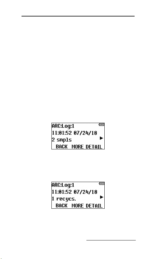
The log generally contains the following
information:
1. The number of samples collected (rc appears
only if some samples required recycling)—
this example indicates the sampling run
that commenced at 11:01 AM on July 24
collected 2 samples].
2. If recycle was activated, the log reports the
number recycles and the alarm output is
activated.
3. That archived data can be reviewed from
the user interface panel by pressing the 5
key when the selected program is running
4-7

Platinum/Optima CVE Refrigerated Sampler
(or waiting to be started), but not while the
DMINISTRATION or PROGRAM menu is
A
active. The first line of the resulting display
will indicate you are viewing log file 1, in
which data for the current (or pending)
sampling run is being (or will be) recorded.
4. Bottle type, number and size of the
containers to which those samples were
discharged.
5. If a log file’s fourth screen indicates one or
more exceptions were encountered, pressing
ETAIL [F3] key will display the
its D
timestamp and type of the first such
exception detected during that program
run. For example:
4-8

Section 4 Operation
If power was lost during the program, the log
reports the time of the power failure event and
the time the power was restored.
6. Pressing the D
ETAIL [F3] key while viewing
any sample container’s screen will display
the timestamp, as well as, the time needed
to collect the first sample that was
discharged to that container. You could then
display the same information for each of the
other samples in that container by pressing
the up and/or down keys.
The refrigerated cabinet temperature is logged
with each sample.
7. The log reports the average refrigerator
temperature and the minimum and
maximum recorded temperatures.
4-9

Platinum/Optima CVE Refrigerated Sampler
4.3.2 User Interface Icon
Table 4-1 User Interface Panel Icons
Message Description
Program is running.
Program is paused.
Time Start: program will
automatically start at a
specified time.
Time Stop: program will
automatically stop at a
specified time.
Sequence table is rotating.
4-10
Recycle is activate/sampling
cycle is being repeated.

Section 4 Operation
Table 4-1 User Interface Panel Icons
Message Description
Alarm Fault
Temperature Alarm
Arrow up / contact closed
(Float circuit closed)
Arrow down / contact open
(Float circuit open)
Power supply voltage
4-11

Platinum/Optima CVE Refrigerated Sampler
4.3.3 Sample Bottle Removal
After the program is complete, the bottles can
be removed and prepared for the laboratory.
1. Gain access to the bottles by releasing the
door latch and swinging the door open.
2. The bottles can then be removed from the
rack by sliding the sequential table forward
until it stops. (Platinum only.)
3. Lift the bottle rack and remove it from the
sampler. *Rotate the discharge tube out of
the way if needed.
*Jog Feature: When the program is in the
ONE or STOP mode the sequential table has a
D
jog feature that allows the table to rotate 90°.
This feature will allow easy access to the sample
bottles when loading or unloading the bottles.
To activate the jog feature:
1. Push the 0 button and the table will jog 90°.
2. When the bottles have been installed, slide
the table back in the refrigerator. Align the
discharge tube (if adjustable) to the center
of bottle 1 after the indexing table has
located bottle 1.
3. Removed bottles should be capped and
labeled according to the protocol established
by your laboratory.
4-12

Section 4 Operation
Figure 4-1 Removing the 24-bottle rack
4.4 Grab Samples
Grab samples let you take a single sample on
demand and collecting it in an external
container. You can collect a grab sample while
the sampler is in R
(volume test sample) can be taken at any time
while the program is running.
Note
When grab samples are taken while a program is
running, the samples are not logged or counted as part
of the number of samples in the program.
UN mode. A grab sample
To collect a Grab Sample:
1. When the program is running, push P
(F3). Then push GRAB (F2) to enter grab
sampling mode.
AUSE
4-13

Platinum/Optima CVE Refrigerated Sampler
2. The screen will display GRAB #1 and is
ready to take a grab sample
When grab sampling is complete, push the
3.
TOP and then F3 CONTINUE. The
F1 S
.
program will take you back to the pause
screen and push F3 R
will return to the R
ESUME. The program
UN screen.
4.5 Velocity Control
Valve
The velocity control valve
adjustment is to control the
inlet velocity of the sample. The
valve is located inside the
refrigerator on the upper right
side of the sample chamber and
can be adjusted by rotating the
knob.
• If the lift height is between 1
and 3 meters, close the valve
all the way (rotate
Figure 4-2
Velocity control
valve
clockwise), then open two complete
rotations (rotate counterclockwise). The
sampler is always shipped at this setting.
• Open the valve all the way if the lift
height is 1 meter or less.
• Close the valve all the way if the lift
height is greater than 3 meters.
4-14

Platinum/Optima
CVE Refrigerated
Sampler
Section 5 Maintenance
This section describes how to maintain your
sampler. If you think your sampler requires
repair, or if you have questions concerning its
operation or maintenance, contact your
authorized Teledyne ISCO service facility or
Technical Service Department:
Phone: (800) 228-4373
(402) 464-0231 (international)
FAX: (402) 465-3001
E-mail: iscoeps@teledyne.com
5.1 Periodic Maintenance Checklist
Perform maintenance as needed.
• Clean or replace the wetted parts
(bottles, suction line, strainer, sample
chamber, discharge tube).
• Clean the sampler when needed.
• Keep the refrigeration air vents clean.
5-1

Platinum/Optima CVE Refrigerated Sampler
5.2 Fuse
The control system operates on 12 VAC power
supplied by a transformer located in the
vacuum pump compartment. Those components
are protected by a fast-acting, 10A/250 V
cartridge fuse. The enclosed fuse holder is
mounted next to the transformer.
• That fuse can be checked and/or replaced
by pulling the front cover of the holder
forward which automatically ejects the
right end of the fuse.
• The control system can be powered down
by tipping the top of the holder up and to
the left.
Figure 5-1 Fuse in the holder
5-2
 Loading...