

Piranha4 Quadlinear
sensors | cameras | frame grabbers | processors | software | vision solutions
Camera User’s Manual
Multispectral RGB + NIR / Monochrome CMOS Line Scan
P/N: 03-032-20217-01
www.teledynedalsa.com

2 Piranha4 RGB + NIR / Mono Camera User's Manual
N oti ce
© 2017 Tel edy n e DA LSA
All information provided in this manual is believed to be accurate and reliable. No responsibility is
assu m ed by T el edy n e D A L SA for i ts use. T el edy n e D A L SA reser ves t h e r ight t o m ak e ch anges t o t h is
information without notice. Reproduction of this manual in whole or in part, by any means, is prohibited
w i t hou t p r ior p erm i ssion h av ing been obtai ned fr om Tel edyn e D A LSA .
M i crosoft and W i ndow s ar e r egi st er ed tr adem ar k s of M i cr osoft Cor p or ati on i n t he U n it ed St at es and
other countries. Window s, Wind ow s 7, Wind ow s 8 ar e tr ademarks of M icrosoft Corporation.
A ll ot h er t r adem ar k s or int el lect u al p rop ert y m en t ioned h erei n b el ong t o t hei r r esp ecti v e o w ner s.
Docu ment D at e: A u gu st 25, 2017
D ocu ment N um b er : 03-032-20217-01
Contact Teledyne D ALSA
Tel ed yn e D A LSA i s headqu art er ed i n W ater l oo, O n t ari o, Canad a. W e hav e sal es o f fi ces i n t he U SA ,
Eu r op e an d A sia, p l u s a w or l dw i d e net w or k of r epr esen t at i v es an d agen t s to ser v e y ou ef fi ci ent l y .
Contact inf ormati on for sales and sup port inquiries, plus link s to m aps and di r ections to ou r of fices, can
be f ou n d her e:
Sal es O f fices: htt p :/ / w w w .t el ed y ned al sa.co m / cor p / con t act / of f i ces/
Technical Support: http:/ / ww w.teledynedalsa.com/ imaging/ support/
About Teledyne D ALSA
Teledyne DALSA is an i nternational high performance semicon d u ctor and elect r oni cs comp any t hat
d esi gn s, d evel op s, m anu f act u res, and mar ket s d i g i tal im agi n g p rod u ct s and so l ut ions, i n ad d i t ion t o
providing wafer foundry services.
Tel ed yn e D A LSA D igi t al I magi n g of f ers t h e w i d est r ange of m achi n e vi si on co m ponen ts in the world.
From industry-l ead ing i mag e sen sor s thr ou gh p ow er f ul and sop hi sti cat ed cam er as, f r ame gr ab b er s,
v i sion p r ocesso r s and sof t w ar e t o easy -to-u se v isi on ap p li an ces and cust om v i sion m o d ul es.
03-032-20217-01 Teledyne DALSA

Piranha4 RGB + NIR / Mono Camera User's Manual 3
Contents
Camera User’s Manual ___________________________________________________________________________________ 1
System Precautions ............................................................................................................................. 6
Precautions .......................................................................................................................... 6
Electrostatic Discharge and the CMOS Sensor ................................................................... 6
1. The Piranha4 RGB + NIR / Monochrome Camera ____________________________________________________________ 7
Camera Highlights ............................................................................................................................... 7
Camera Performance Specifications ................................................................................................... 8
Certifications ........................................................................................................................ 10
Flash Memory Size .............................................................................................................. 10
Supported Industry Standards ............................................................................................................. 10
Sensor Contrat Ration & Responsivity ................................................................................................ 11
Responsivity ........................................................................................................................ 11
Spatial Correction and Quadlinear Sensor Design .............................................................. 12
Parallax Correction .............................................................................................................. 16
Camera Direction ................................................................................................................. 17
Mechanicals ......................................................................................................................................... 18
Camera Mounting and Heat Sink Considerations ................................................................ 19
2. Quick, Simple Steps to Acquire an Image ___________________________________________________________________ 20
3. Software and Hardware Setup ____________________________________________________________________________ 21
Recommended System Requirements ................................................................................ 21
Setup Steps: Overview ........................................................................................................................ 21
1. Install and Configure Frame Grabber and Software ........................................................ 21
2. Connect Camera Link and Power Cables ........................................................................ 21
3. Establish communicating with the camera ....................................................................... 21
4. Operate the Camera ........................................................................................................ 21
Step 1. Install and configure the frame grabber and software ............................................................ 22
Install Frame Grabber .......................................................................................................... 22
Install Sapera LT and CamExpert GUI ................................................................................ 22
Step 2. Connect Data, Trigger, and Power Cables ............................................................................. 23
Data Connector: Camera Link ............................................................................................. 24
Camera Link Bit Definitions ................................................................................................. 24
Camera Timing .................................................................................................................................... 25
Camera Link cable quality and length .................................................................................. 34
Input Signals, Camera Link .................................................................................................. 34
Output Signals, Camera Link Clocking Signals ................................................................... 34
Power Connector ................................................................................................................. 35
LEDs .................................................................................................................................... 35
Step 3. Establish Camera Communication .......................................................................................... 36
Power on the camera ........................................................................................................... 36
Connect to the frame grabber .............................................................................................. 36
Connect to the camera ........................................................................................................ 36
Check LED Status ............................................................................................................... 36
Software Interface ................................................................................................................ 36
Using Sapera CamExpert with Piranha4 Cameras ............................................................................. 37
Teledyne DALSA 03-032-20217-01

4 Piranha4 RGB + NIR / Mono Camera User's Manual
CamExpert Panes ................................................................................................................ 38
Review a Test Image ........................................................................................................... 40
4. Camera Operation _____________________________________________________________________________________ 41
Factory Settings ................................................................................................................................... 41
Check Camera and Sensor Information .............................................................................................. 41
Verify Temperature and Voltage .......................................................................................................... 42
Saving and Restoring Camera Settings .............................................................................................. 43
Camera Link Configuration .................................................................................................................. 45
Trigger Modes ..................................................................................................................................... 45
Exposure Controls ............................................................................................................................... 45
Exposure Modes in Detail .................................................................................................................... 47
Color Exposure Time Guidelines ......................................................................................... 49
Set Line Rate ....................................................................................................................................... 49
Set Exposure Time .............................................................................................................................. 50
Control Gain and Black Level .............................................................................................................. 50
Set Image Size .................................................................................................................................... 50
Set Baud Rate ..................................................................................................................................... 51
Pixel Format ........................................................................................................................................ 51
Camera Direction Control .................................................................................................................... 52
Pixel Readout Direction (Mirroring Mode) ........................................................................................... 52
Resetting the Camera .......................................................................................................................... 52
Calibrating the Camera ........................................................................................................................ 53
Appendix A: GenICam Commands __________________________________________________________________________ 57
Camera Information Category ............................................................................................................. 57
Camera Information Feature Descriptions ........................................................................... 58
Camera Configuration Selection Dialog ............................................................................... 61
Camera Power-up Configuration ......................................................................................... 61
User Set Configuration Management .................................................................................. 61
Camera Control Category .................................................................................................................... 62
Camera Control Feature Descriptions ................................................................................. 63
Independent Exposure Control ............................................................................................................ 66
Digital I/O Control Feature Descriptions .............................................................................. 68
Flat Field Category .............................................................................................................................. 69
Flat Field Control Feature Description ................................................................................. 69
Region of Interest (ROI) ....................................................................................................... 71
Image Format Control Category .......................................................................................................... 71
Image Format Control Feature Description ......................................................................... 73
Area of Interest (AOI) Setup ................................................................................................................ 74
Instructions on using the camera scan direction to control camera parameters ................................. 77
Transport Layer Control Category ....................................................................................................... 80
Transport Layer Feature Descriptions ................................................................................. 81
Acquisition and Transfer Control Category .......................................................................................... 82
Acquisition and Transfer Control Feature Descriptions ....................................................... 82
Serial Port Control Category ................................................................................................................ 83
Serial Port Control Feature Descriptions ............................................................................. 83
File Access Control Category .............................................................................................................. 84
File Access Control Feature Descriptions ............................................................................ 85
03-032-20217-01 Teledyne DALSA

Piranha4 RGB + NIR / Mono Camera User's Manual 5
File Access via the CamExpert Tool .................................................................................... 86
Download a List of Camera Parameters .............................................................................. 87
Appendix B: ASCII Commands _____________________________________________________________________________ 89
Port Configuration ................................................................................................................ 90
Commands .......................................................................................................................... 91
Appendix C: Quick Setup and Image Acquisition _______________________________________________________________ 104
Appendix D: The Sensor Window ___________________________________________________________________________ 107
Cleaning and Protecting Against Dust, Oil, and Scratches .................................................. 107
Cleaning the Sensor Window .............................................................................................. 108
Appendix E: Camera, Frame Grabber Communication ___________________________________________________________ 109
Setting Up Communication between the Camera and the Frame Grabber ......................... 109
Appendix F: Error and Warning Messages ____________________________________________________________________ 112
EMC Declaration of Conformity _____________________________________________________________________________ 114
Revision History _________________________________________________________________________________________ 115
Index _________________________________________________________________________________________________ 116
Teledyne DALSA 03-032-20217-01

6 Piranha4 RGB + NIR / Mono Camera User's Manual
System Precautions
Precautions
Read these p r ecaut i on s an d th i s man u al car ef ul l y bef or e usi ng t he cam er a.
Confirm that the cam era’ s pack agi ng i s u nd am aged bef or e open i ng i t. I f th e p ack agi ng i s dam aged p lease
cont act t he r el evant logistics personnel.
D o n ot op en t h e h ou sin g of the cam er a. The w arr ant y is v oi ded if the h ou si ng i s op ened .
K eep the cam era hou si ng t emp er atu r e in a r an ge of 0 °C to 65 °C during op eration.
D o n ot op er ate t h e cam er a i n t he v i cin i t y of str o n g el ectr o m agnet i c f i eld s. I n ad d it ion, av o i d el ect r ost at i c
char g i ng, v i ol ent vi br ati on, and excess moi stu r e.
To cl ean t h e d ev i ce, avoid electrostatic charging by usi n g a d r y, cl ean absor ben t cot ton cl ot h d amp en ed
with a small quantity of pure alcohol. Do not u se m eth yl at ed al cohol . To cl ean t he su rf ace of t h e camer a
hou si ng, use a sof t , d ry cl o t h. T o r emov e sev er e st ai n s use a sof t cl ot h dam pened w i t h a sm al l qu antity of
neu t ral deter gen t and then w i p e dr y . Do not u se vol ati l e sol ven t s such as ben zen e and t hi n ner s, as t h ey
can d am age t he su r face f i ni sh. Fur ther cl eani n g i nst r uct i on s are bel ow .
Though this camera supports hot plugging, it is recommended that you pow er dow n and d i scon n ect
p ow er t o t he cam er a bef or e you ad d or rep lace syst em com p onent s.
Electrostatic Discharge and the CMOS Sensor
Im age sen sor s and the camera bodies housing ar e suscep ti bl e to d am ag e f rom el ectr ost ati c d i schar g e
(ESD). El ect r ostati c charge introduced to the sensor window surface can induce charge buildup on the
u n d er si d e of t he w i n d ow th at can n o t be r ead i ly d i ssi p at ed by t he d r y n i tr ogen gas i n t he sensor pack age
cav i t y. T h e char ge nor m all y d issi pat es w i t hi n 24 h ou r s an d t he sensor r eturns to nor m al operation.
Additional information on cleaning the sensor window and protecting it against dust, oil, blemishes, and
scratches can be found her e: A pp en di x D: T h e Sensor W i ndow .
03-032-20217-01 Teledyne DALSA

Piranha4 RGB + NIR / Mono Camera User's Manual 7
1. The Piranha4 RGB + NIR /
Monochrome Camera
Camera Highlights
Th e n ew Pir anha4 quad l i n ear multispectral RGB + N IR / M on o cam er as p r ov id e i n d ust r y l eadi ng speed s
th at m eet f u tu r e r eq u ir ement s o f hi g h er t h r ou g h p ut i n mul tispectral imaging applications.
Based on T el edy ne D A LSA ’ s un iqu e CM OS l i ne scan technology, the Piranha4 multispectral
cam era d el i v er s sup er b col or pl us near -infrared (NIR) fidelity, spectrally independent outputs,
al l i n a com p act f oot pr int and w i t h an easy to u se i nt er face. N ew f eatu r es incl ude m ul t ipl e
regions of interest for data reduction and regional calibration, sub-pixel spatial correction,
w hi te bal ance an d col or cal i br at ion tool s.
Key Features
• H i g h sp eed: up to 70 k H z l in e r at es
• Thr ee n ati ve col or s (RGB) p l us N IR / Mono per pi xel
• Spectr al l y I nd epen d ent RG B + N IR outputs
• Bi -directional
• Com p act cam er a bod y
• Su b -pixel spatial correction
• H or izon t al Par all ax Cor rect i on
Programmability
• Multiple Regions of Interest for cali br ati on and d ata r edu ct ion
• 8, 10, or 12 bi t out p u t
• Flat field and lens shading
• cor recti on
• 8 p r ogr amm abl e coef f ici ent set s
• GenICam or A SCII compliant interfacing
Applications
• 100% p r i n t inspect i on (p h ar maceu ti cals, b an k not e)
• Electronics inspection
• M ater i al s g r adi ng sy stem s
• W eb i nspect i on
• H i gh performance color sorting sy stem s
• Food i nspection
• Gen eral pu r po se m ach i ne v isi on
Teledyne DALSA 03-032-20217-01

8 Piranha4 RGB + NIR / Mono Camera User's Manual
P4-CC-02K 07Q -00-R
2k r esol u t i on, 70 k H z l ine rat e, 14.08 µm x 14.08 µ m p ixel si ze, RGB + M ono
Cam era f i rm w are
Em b ed ded w it h in cam er a
Gen ICam ™ su pp or t (XM L cam er a descr ip t i o n f i l e)
Embedded within camera
Sapera LT, including CamExpert GUI application and
V er si o n 7.2 or lat er
I m ager For m at
C M O S quad l inear : color (RGB) plus N IR / M ono C M O S line scan
Pixel Size
14.08 µm x 14.08 µm
Bit Depth
8, 10, and 12 bits, sel ect abl e
or Deca confi gurations
Power Supply
+ 12 V to + 24 V D C
M ass
< 340 g (without heat sinks)
Sensor t o Camer a Fr ont D i stan ce
12 mm
Models
The cam er a i s av ail abl e in t h e foll ow i ng configurati ons:
Table 1: Camera Models Overview
Model Number Description
P4-CC-02K07N-01-R 2k r esol u t i on, 70 k H z l ine rat e, 14.08 µm x 14.08 µm pixel size, RGB + N IR
Table 2: Software
Software Product Number / Version Number
Gen ICam f or Cam er a L i n k i magi ng d ri v er
Camera Performance Specifications
Table 3: Camera Performance Specifications
Specifications Performance
Resoluti on 2048 x 4 pixels
Line Rate 0 k Hz minimum to 70 k H z maxi mum
Exposure Time 7 µs minimum to 3,000 µs maximum
Connectors and Mechanicals
Control & Dat a Interf ace 2 SD R-26 mini Camera L i nk conn ect or s u sed to transmit Base, M edi u m, Fu l l ,
Power Connector H ir o se 6-pin circular
Power Dissipation 8 W
Si ze 62 mm (W) x 62 mm (H) x 48 mm (D)
Oper ati n g T em p 0 °C t o 65 °C, front plate temperature
Optical Interface
Lens M ount M42 x 1
F-mount ad ap t er av ai l abl e
Sensor Alignment (aligned to sid es of camer a)
Fl atness
Θ y (parallelism)
x
y
z
Θ z
50 µm
0.08° or 81 µm
± 100 µm
± 100 µm
± 250 µm
± 0.2°
Compliance
Regulatory Compliance CE, FCC and RoH S, GenI Cam
03-032-20217-01 Teledyne DALSA

Piranha4 RGB + NIR / Mono Camera User's Manual 9
DC Offset
< 11 DN
< 11 DN
< 11 DN
< 11 DN
PRN U
< 2% @50% Sat
< 2% @50% Sat
< 2% @50% Sat
< 2% @50% Sat
FPN
< 6.3 D N
< 6.3 D N
< 6.3 D N
< 6.3 D N
SEE
3.96 n J / cm 2
4.39n J / cm 2
6.80 n J / cm 2
3.64 n J / cm 2
Dy n am i c Rang e
61 dB
61 dB
61 dB
61 dB
Random N oi se
3.52 D N ** r m s
3.00 D N rm s
2.50 D N rm s
3.52 D N rm s
SEE
4.76 n J / c m 2
5.1n J / c m 2
6.07 n J / c m 2
8.3 n J / c m 2
N EE
4.2 p J / c m 2
3.9 p J / c m 2
3.8 p J / c m 2
2.1 p J / c m 2
Antibloomi ng
> 100 x Sat ur ati on
Table 4: P4-CC-02K07Q-00-R Operating Specifications
Operating Ranges Performance
Red Green Blue Mono
Dy n am i c Rang e 61.8 d B 61.8 d B 61.8 d B 61.8 d B
Random N oi se 3.36 D N ** r m s 3.36 D N rm s 3.36 D N rm s 3.36 D N rms
Resp onsi v it y Ref er to g r aph
Gai n 1x to 10x Nominal Range (not including individual RGB g ai ns for w hi t e bal an ce)
N EE 3.2 p J / cm2 3.6 pJ / cm 2 5.6 p J / cm2 3.0 p J / cm2
Antibloomi ng > 100 x Sat ur ati on
Integral nonlinearity
< 2% DN
**DN = digital number
Test Conditions:
• V al ues measur ed usi n g 12-bi t , 1x gai n .
• 10 k H z l ine r at e
• L i ght so u rce: w hi te L ED
• No white balancing
• Front plate t em p erat ur e: 45º C
Table 5: P4-CC-02K07N-01-R Operating Specifications
Operating Ranges Performance
Red Green Blue NIR
Resp onsi v it y Ref er to g r aph
Gai n 1x to 10x Nominal Range (not including individual RGB gains for white balance)
DC Offset < 11 DN < 11 DN < 11 DN < 11 DN
PRN U < 2% @50% Sat < 2% @50% Sat < 2% @50% Sat < 2% @50% Sat
FPN < 4.7 DN < 4.7 D N < 4.7 D N < 5.7 DN
Integral nonlinearity
< 2% DN
**DN = digital number
Test Conditions:
• V al ues measur ed usi n g 12-bi t , 1x gai n .
• 10 k H z l ine r at e
• L i ght so u rce: w hi te L ED
• No white balancing
• Front plate temperature: 45º C
Teledyne DALSA 03-032-20217-01

10 Piranha4 RGB + NIR / Mono Camera User's Manual
EN 55024, and EN 61326-1 Immunity to Disturbance*
Certifications
Compliance
EN 55011, FCC Par t 15, CI SPR 11, an d ICES-003 Cl ass A Rad i ated Emi ssi on s Req u i r em en t s
RoH S p er EU D i recti v e 2002/ 95/ EC and W EEE per EU D ir ecti v e 2002/ 96/ EC an d Chi n a El ectr o n i c Indust r y
Stand ar d SJ/ T 11364-2006*
GenICam XML Description File, Sup erset of t he G en I Cam ™ Stand ar d Feat u r es N am ing Convention specification
V1.5, Camera Link Serial Communication: GenICam™ Generic Control Protocol (GenCP V1.0)
Flash Memory Size
Camera Flash Memory Size
P4-CC-02K 07Q -00-R 16 M By te
P4-CC-02K 07N -01-R 16 M Byte
Supported Industry Standards
GenICam™
Pi r anha4 cam er as are Gen I Cam com pl i ant. T h ey imp l emen t a super set of t he GenI Cam ™ Stan d ard
Featu r es N am ing Co n v ent ion speci f icat ion V 1.5. Th i s descr ip t i o n t ak es t he f or m of an XM L d ev i ce
d escr ip t ion f il e resp ect i ng t he sy nt ax d efi n ed by the GenA pi mod ul e of t he Gen ICam ™ sp eci f icat i on. The
cam er a u ses t h e Gen I Cam ™ Gen er i c Co n t rol Prot ocol (GenCP V 1.0) t o com mu n icat e ov er t h e Cam er a
Link serial port. For more inf or m ati on see www.genicam.org
.
03-032-20217-01 Teledyne DALSA
Piranha4 RGB + NIR / Mono Camera User's Manual 11
Sensor Responsivity and Design
Responsivity
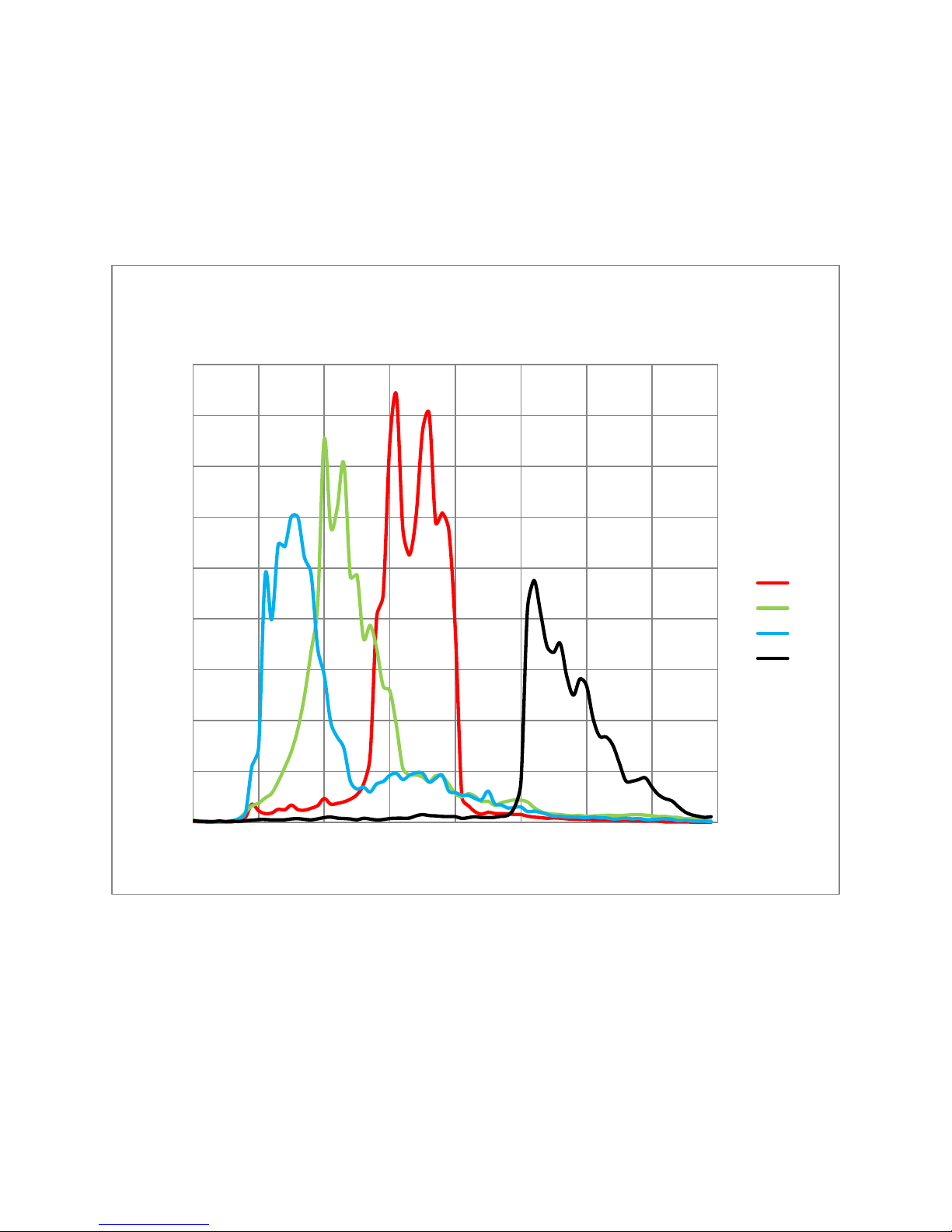
The responsivity graph i l l u st r at es the sen so r ’s r esponse t o d if fer ent w av el eng t hs of l i ght (ex cl u di ng l ens
and l ight sour ce char act eri st i cs).
Piranha4 2K Quad NIR Spectral Responsivity
(12Bit)
900
800
700
)
2
600
500
400
300
Responsivity (DN/ɳJ/cm
200
100
0
300 400 500 600 700 800 900 1000 1100
Red
Green
Blue
NIR
Wavelength (ɳm)
Figure 1: Spectral Responsivity (NIR)
Teledyne DALSA 03-032-20217-01
12 Piranha4 RGB + NIR / Mono Camera User's Manual
0
200
400
600
800
1000
1200
350 450
550 650
750 850
950
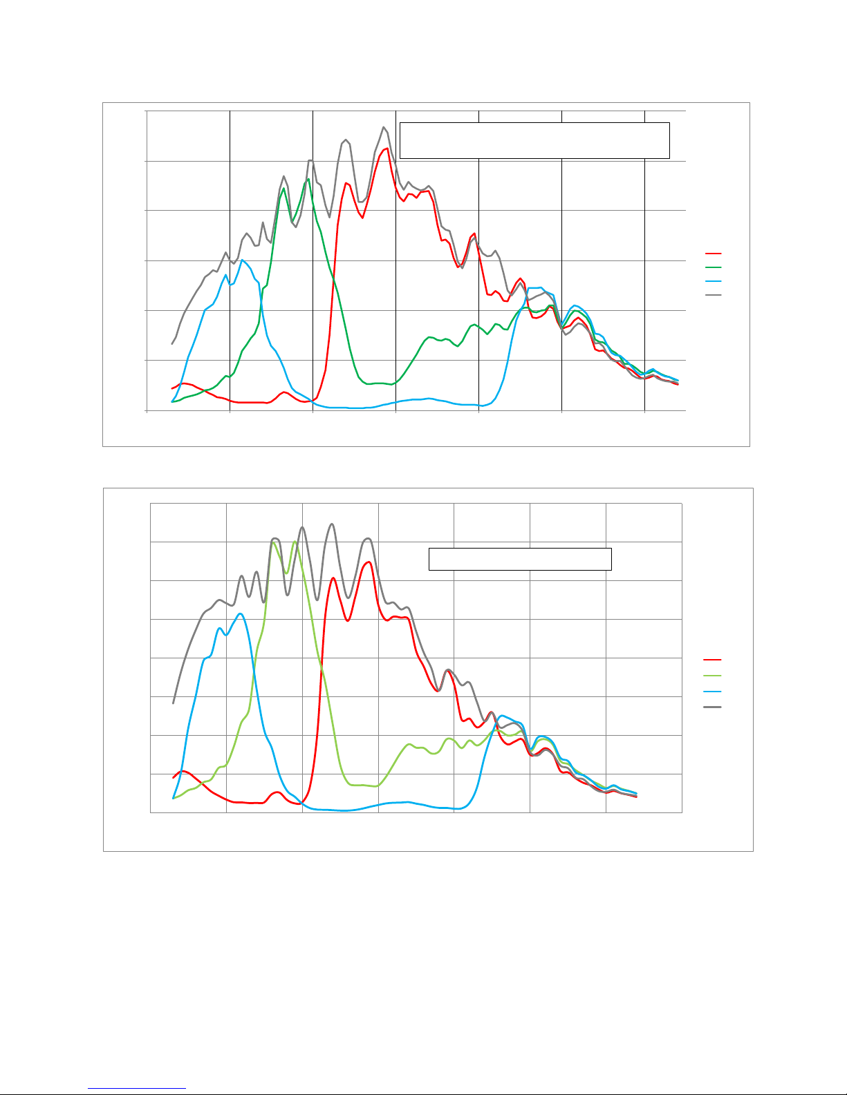
Spectr al Responsivity (DN/nJ/ cm^2)
Wavelength (nm)
P4 2K Quad Linear Color Spectral Responsivity
No White Balance, 12 bit, gain 1x
Red
Green
Blue
Mono
0%
10%
20%
30%
40%
50%
60%
70%
80%
350 450 550 650 750 850 950 1050
QE %
Wavelength (nm)
QE vs Wavelength 2K Quad
Red
Green
Blue
Mono
Figure 2: Spectral Responsivity (Monochrome)
Figure 3: QE vs. Wavelength
03-032-20217-01 Teledyne DALSA
Piranha4 RGB + NIR / Mono Camera User's Manual 13
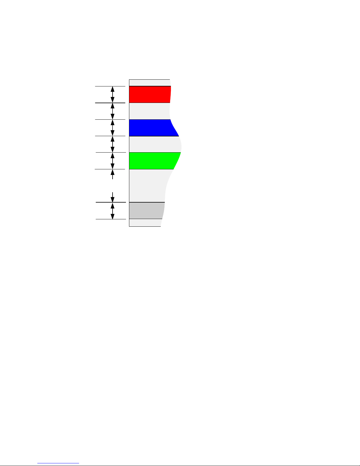
14.08um
14.08um
Red
Blue
Green
14.08um
14.08um
14.08um
Mono
14.08um
42.24um
Spatial Correction and Quadlinear Sensor Design
The P4-CC-02K07Q-00-R cam era u ses a quad li n ear sensor w h er e fou r sep ar ate 2K l i nes of pi x el s are
u sed —on e for r ed , on e for blue, on e f or g r een, an d the l ast for monochrome / N IR.
Figure 4: 2K Quadlinear Sensor Line Spacing Diagram
In the case of the 2k cameras, only a single l in e of space sep ar at es the co l or ed l i nes—w it h th e ex cep ti on of
the monochrome line, which has three lines of spacing.
W h en the i mage p asses th e t hr ee l ines of p ix el s, t he r ed, b l ue an d gr een co m ponen t s for t he sam e i mage
l ocat i on ar e capt u r ed at a di f fer ent ti me as d ict at ed by th e l i n e spaci ng . The cam er a au t om ati cal ly cor r ect s
f or the l in e sp aci ng t o en sur e that t he r ed , bl ue and gr een com p on en ts of t he i mage p i xel ar e al l al ign ed
w hen ou t pu t . H ow ever , t h i s is onl y cor r ect w hen t h e o b ject pi xel size i s sq u ar e; i .e., t h e di stance m ov ed
by t he object for o n e EX SY N C per iod i s equ al to t h e w i d th of the object p i x el . I n som e ap p li cat i on s i t may
not be p o ssi bl e to achi eve a ‘square’ object pixel as fine adjustment of the lens magnification and/ or the
d i st ance m o v ed f or each EXSYN C per i od is n o t possi bl e. T h i s scenar io may be especi all y app ar ent when
trying to integrate the camer a i nt o an exi st ing system .
W h en it is n ot p ossi bl e t o gen er at e a sq u ar e o bject pi xel , col or ar t efact s w i l l occu r i n t h e scan d i rect ion
and i s par ti cul arl y not i ceabl e at shar p edge tr ansi ti on s. T h e si ze of t h e ed ge ar t efact i s pr op or t ion al t o
how far t he p ixel i s fr om squ ar e. To cor r ect f or t hi s, t h e cam era has a f eat ure, L ine Spat i al Cor rect i on (or
t h r ee lett er com man d ssa), which allows fine adjustment of the compensation mechanism the camera uses
t o cor r ect f or the l i n e sp aci ng.
The default setting f or th is f eatu r e is 2, w hi ch i s set f or squ ar e object pi x els. T he set ti ng can be ad ju sted
f r om 0 t o 5 t o comp en sat e f or rect an gu l ar p i x el s—w hether they are too long or to short.
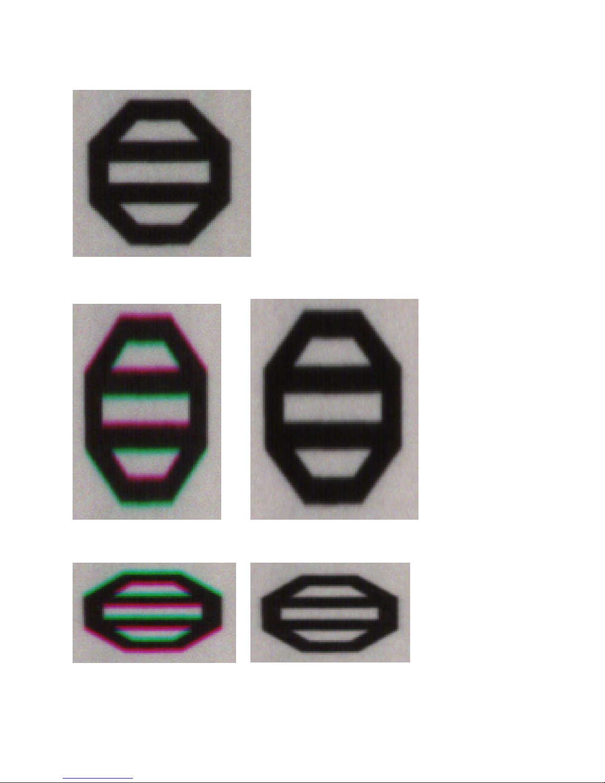
The fol l owing ex amp l es of i m age ar t ef acts show bl ack to w hi t e image t r ansi t i ons and the associated
cor r ected i m ag e af ter ap p ly in g a speci f ic line spatial correction (ssa) sett i ng.
Teledyne DALSA 03-032-20217-01
14 Piranha4 RGB + NIR / Mono Camera User's Manual
Example 1. Target speed adjusted for square pixels
L i ne Spati al Cor rect i on = 3 ( ssa = 3). This is the default condition.
Example 2. Target running slower than example 1, same EXSYNC (trigger) frequency
L i ne Spati al Cor rect i on = 3 ( ssa = 3) Li n e Spati al Cor recti on = 4.3 (ssa = 4.3)
Example 3. Target running faster than example 1, same EXSYNC (trigger) frequency
L i ne Spati al Cor rect i on = 3 (ssa = 3) L i ne Spati al Cor rect i on = 1.73 (ssa = 1.73)
03-032-20217-01 Teledyne DALSA
Piranha4 RGB + NIR / Mono Camera User's Manual 15
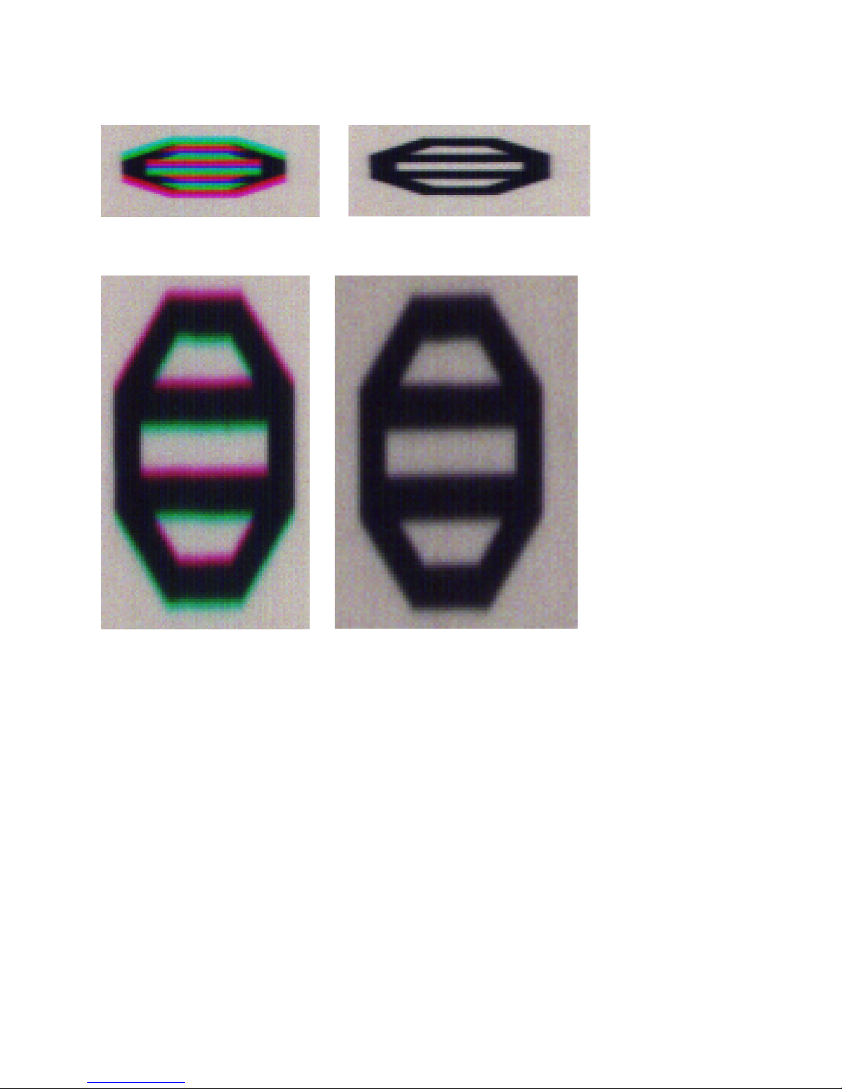
Example 4. Target running slower than EXSYNC
L i ne Spati al Cor rect i on = 3 ( ssa = 3) L i ne Spati al Cor rect i on = 1 ( ssa = 1)
Example 5. Target running faster than EXSYNC
L i ne Spati al Cor rect i on = 3 ( ssa = 3) Li ne Spat i al Cor r ecti on = 5 (ssa = 5)
Teledyne DALSA 03-032-20217-01

16 Piranha4 RGB + NIR / Mono Camera User's Manual
4096 pixels
4096 pixels
2048 p i xel s
2048 p i xel s
Parallax Correction
W h en the cam era i t i s n ot p erp en d i cu l ar t o t he object surface the P4 color camera will exhibit color. The
par all ax d ist or t ion i ncr eases when i m agi n g at st eep an gl es r el ati v e to t he cam eras i m agi ng pl ain. Th i s is
an optical effect caused by the line spacing of the three individual colors. This spacing r esu l ts i n a
different magnification for each line at high angles. A s show n in t h e fi gu re bel o w , there is col or d istor tion
at t he ext r emes en d s of the i m ag e bu t at th e cen tr e of the i mage t he col or di st or ti on d oes n o t sho w up .
Figure 5: Image with Horizontal Color Alignment Issues
U si ng t h e P4 col or camer as Par all ax Cor rect i on f eatu r e, t he opt i cal m agn i fi cati on f or each l in e i s adju st ed
such t hat col or s can be l in ed up at t h e ext r em e end s of the i mage without affecting the center. Using the
f eat ur e Im age D i st or ti on C or rect ion M od e (sh m = 1) t h i s feat u r e can be t u rn ed on . U sing t he f eatur e
I m age Di stor t i o n Cor r ecti on L i n e Sel ector t he u ser can sel ect r ed and g r een t o cor r ect th e d ist or ti on . N ot e.
The r ed and gr een l ines ar e ad j u sted t o t o al ign w it h t he cen t er bl ue l i ne. I m age D i sto r ti on Par al l ax
Co r r ect i on Pi xel St r et ch (sha - Set horizontal alignment in float f<value 0-3>) is used to add the amount
of cor rect ion n eed ed t o t he i m age. Th e v al ue ent er ed her e m ust b e b et w een 0 an d 3 (d eci m al v alu es ar e
accep ted .
Figure 6: CamExpert Parallax Correction Controls
Figure 7: Figure 8 Corrected Image
The f i gu r e abov e i s the sam e im age cor r ect ed usi ng t he p ar al lax co r r ect i o n . I n thi s exam p le t he v alu e o f 3
w as u sed to cor r ect t h e i mage.
03-032-20217-01 Teledyne DALSA
Piranha4 RGB + NIR / Mono Camera User's Manual 17
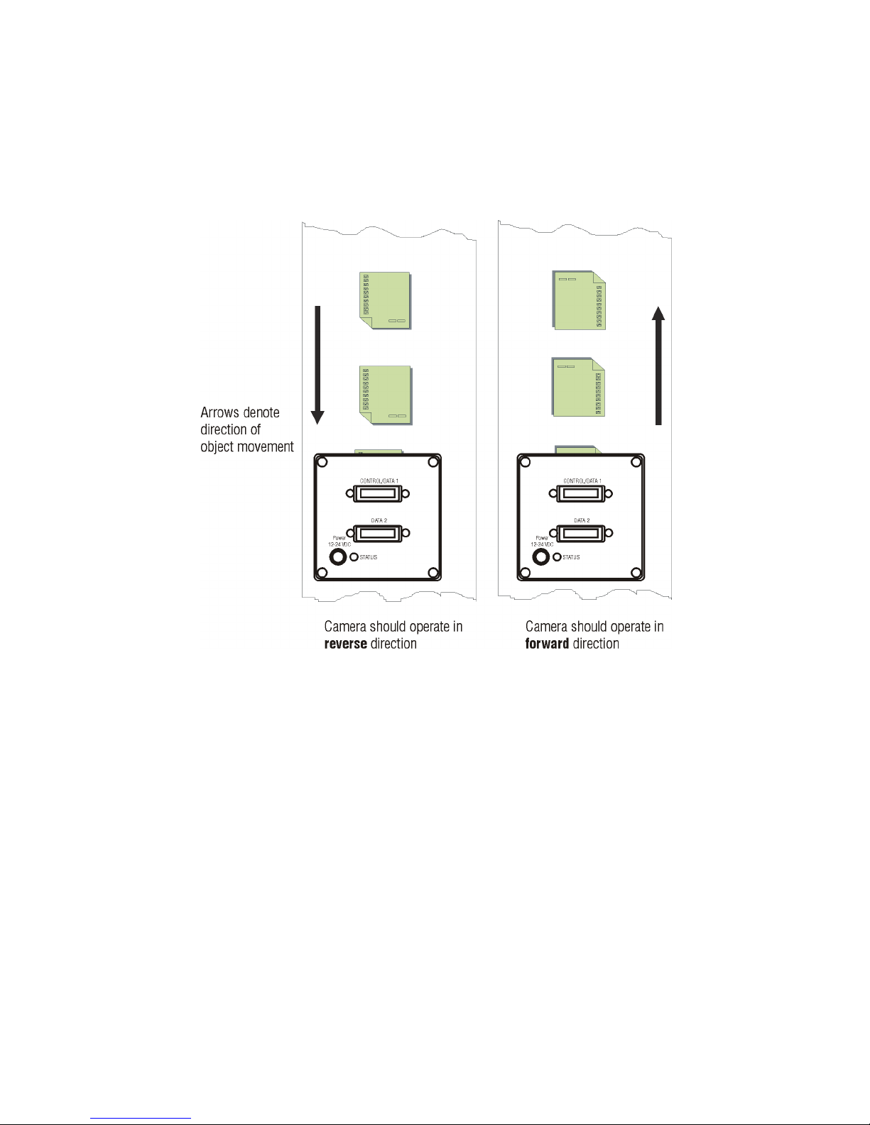
Camera Direction
Select ab l e cam er a d i rect i on acco m m od ates an object direct i on change on a web and all ow s y ou to mount
t h e cam er a “ up sid e dow n” .
Note: The ex am p le h er e assu m es the u se of a l en s (w hi ch i n ver ts t h e i mage).
Figure 9: Object Movement and Camera Direction Example, with a Lens
Teledyne DALSA 03-032-20217-01

18 Piranha4 RGB + NIR / Mono Camera User's Manual
Mechanicals
[ADD MECHANICALS]
Figure 10: Camera Mechanical
03-032-20217-01 Teledyne DALSA
Piranha4 RGB + NIR / Mono Camera User's Manual 19
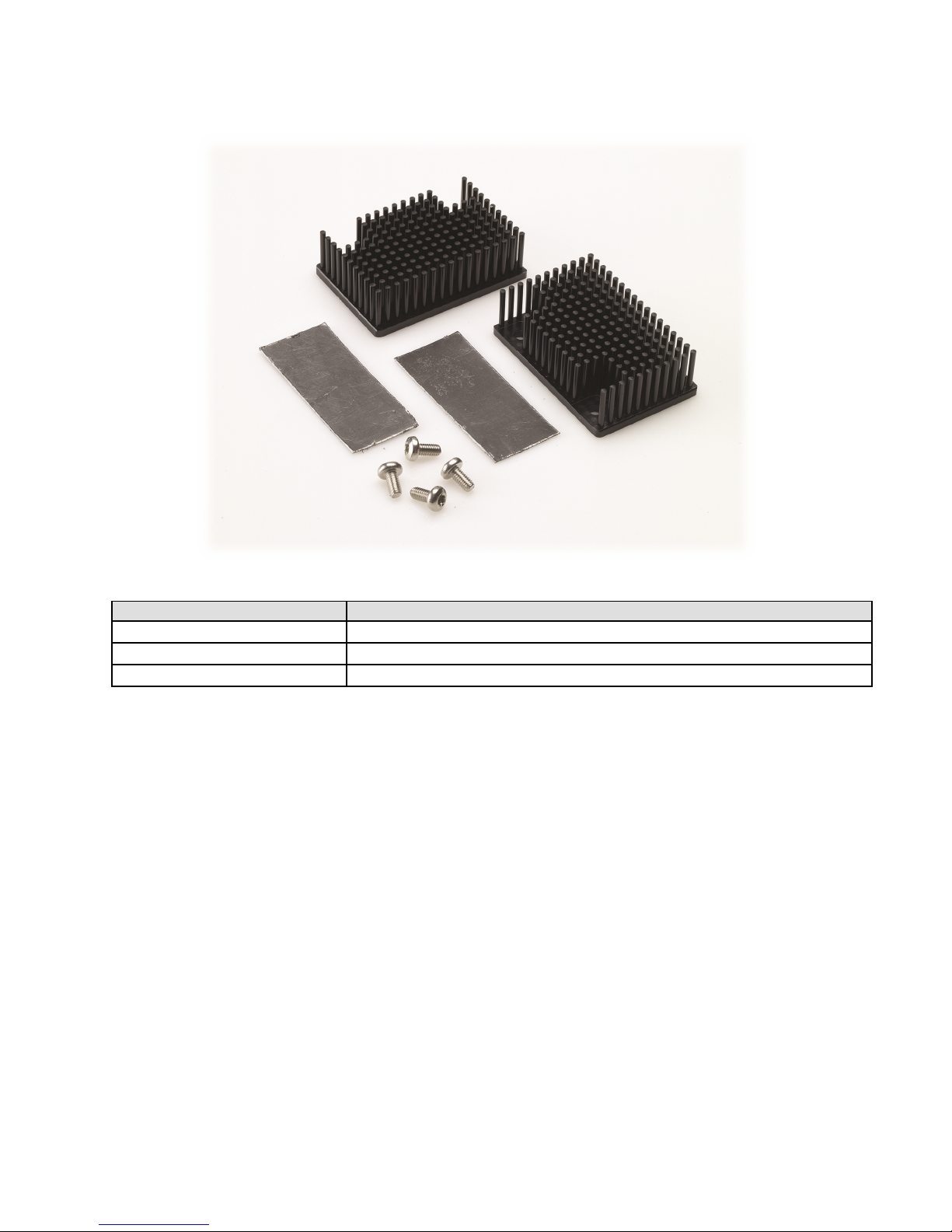
H eat si nk
AC-MS-00108-01-R
Figure 11: Piranha4 Heat Sink Accessories Kit
Optional Lens Mount and Heat Sink Accessories
Description Description
M 42 to F-m ou n t ad apt er AC-LA-00115-A0-R
M 42 to C-mou n t ad apt er AC-LC-00001-00-R
Camera Mounting and Heat Sink Considerations
Up to two optional heat sinks can be installed on the cam er a. As illustrated, they are ideally positioned t o
al low close sp aci n g of t he cam er as. These h eat si nk s ar e desi g n ed to p rov i de ad eq u ate convect i on cooli ng
w hen n ot ob st r u ct ed by encl o su res or mou n ti n g assem b l ies.
Tel ed yn e DALSA recognises that each cu st om er ’s app l i cat ion can be unique. In consideration, cam er a’s
heat si n k s hav e been d esign ed in su ch a w ay t h at th ey can be r eposi t i oned on the d i ff er ent f aces of th e
cam era or rem o v ed en t ir el y , depending on the mounting configuration and its heat sinking potential.
Rep o si ti on i ng or rem o v al of t he heat si nk s m u st be per f or med w i t h car e in or d er t o av oi d tem p er at ur e
i ssu es. T h e cam er a has t h e abi li ty t o m easur e i t s in t er n al t emp er atur e. U se thi s feat ur e t o r ecor d th e
i n ter n al t emp er atur e of the camer a w hen i t i s m ou n ted i n y ou r sy st em an d oper ati ng un d er t he w or st
case con di ti on s. The camera will stop outputting data if i ts i nter nal tem p erat ur e reach es 80 °C.
Teledyne DALSA 03-032-20217-01

20 Piranha4 RGB + NIR / Mono Camera User's Manual
2. Quick, Simple Steps to
Acquire an Image
For u ser s who ar e fami l iar w i t h C am er a L i nk cam er as, have a basic understanding of their i maging
r eq u ir ement s, and w ho ar e pr im ar i ly i nt erest ed i n eval uat i n g t he cam er a, an o v er v iew of th e st eps
r eq u ir ed to get this cam era op erati onal and acqui r ing i mag es qui ckl y can be f ou n d in Appendix C: Quick
Setup and Image A cquisition.
03-032-20217-01 Teledyne DALSA

Piranha4 RGB + NIR / Mono Camera User's Manual 21
3. Software and Hardware Setup
Recommended System Requirements
To achi eve best sy st em per f or m ance, t he f ol l ow in g m in i mu m r equ i rem en t s ar e r ecom mend ed :
• High bandwidth frame gr abber , e.g. Xcel er a-CL PX 8 Full Camera Link frame grabber (Part # OR-
X8CO-XPF00): www.teledynedalsa.com/imaging/products/fg/OR-X8C 0-XPF00/
• Op er at i ng sy stem s: W i nd ow s XP / Vist a / 7, 32 / 64-bit.
Setup Steps: Overview
Tak e t he f ol l ow ing st ep s i n or d er to setup and run your cam er a syst em . They ar e d escri b ed br ief l y bel ow
and in more detail in the sections that follow .
1. Install and Configure Frame Grabber and Software
W e r ecom m end th e Xcel era-CL PX8 Full frame grabber or equivalent, described in detail on the
t el edy ned alsa.com si te her e
then you will need to install one. Follow the manufacturer’s installation instructions.
A GenCP (Generi c Control Protocol) compliant XML device description file is embedded within the
camer a firmw ar e all ow i n g GenCP-comp l i an t ap pl i cati ons t o k no w the camer a’ s cap ab i li t i es i mm ed i atel y
af t er co n n ecti on . I nstal l i ng Saper aL T gi ves y ou access t o t h e Cam Exp er t GU I , a tool that supports GenCPcom p li an t d ev i ces.
. If your host comp u t er d oes not hav e a PX8 ful l Cam er a L i n k f r ame gr abber
.
2. Connect Camera Link and Power Cables
• Connect t he Cam er a Li n k cab l es fr om the cam era t o t he comp u ter .
• Co n n ect a p ow er cab l e fr om t he camer a to a + 12 VDC t o +24 V DC power supply.
3. Establish communicating with the camera
Start the GUI and establish communication with the camer a.
ASCII Commands
A s an al ter nat iv e t o t he Cam Ex p ert (or eq u i v al en t) GU I, y ou can com mu n i cate w it h thi s cam er a usi n g
A SCI I -b ased com man d s. A complete list of the com m and s can be found her e, Appendix B: ASCII
Command s.
4. Operate the Camera
At this point you will be ready to start operating the camer a in order to acquire i mages, set camer a
functions, and save settings.
Teledyne DALSA 03-032-20217-01

22 Piranha4 RGB + NIR / Mono Camera User's Manual
Step 1. Install and configure the frame grabber
and software
Install Frame Grabber
I n st al l a Full configurati on Cam era Link frame grabber according to the manufacturer’s description.
W e r ecom m end th e Xcel era-CL PX8 frame grabber or equivalent , d escr i bed i n d etai l on the
t el edy ned alsa.com si te her e
Install Sapera LT and CamExpert GUI
Communicate w ith the camera using a Camera Link-compliant int er f ace. W e r ecomm end y ou use
CamEx p er t . CamEx p er t i s t he cam er a i n t erf aci ng t ool sup p or ted by t he Saper a l ibr ar y and com es
bundled with SaperaLT. Usi ng C amEx p ert i s the si mp l est and qu ick est w ay t o sen d com m and s t o and
r ecei v e inf or mat i on f rom t he cam era.
Cam er a Link Environment
These cam eras i mp lemen t th e Cam era l i n k sp eci fi cat i on, w hi ch d ef ines t h e dev i ce cap abi li t ies.
The Cam er a l ink XM L d evi ce d escr i pt i on f i l e i s em bed d ed w it h in t he cam er a fi rm w ar e al l ow ing Cam er a
link-com pliant applicat i ons to recogni ze t he camer as’ cap ab i li t i es i mm ed i atel y af t er con n ecti on .
.
03-032-20217-01 Teledyne DALSA
Piranha4 RGB + NIR / Mono Camera User's Manual 23
!
B
B
A
Power
A
B
C
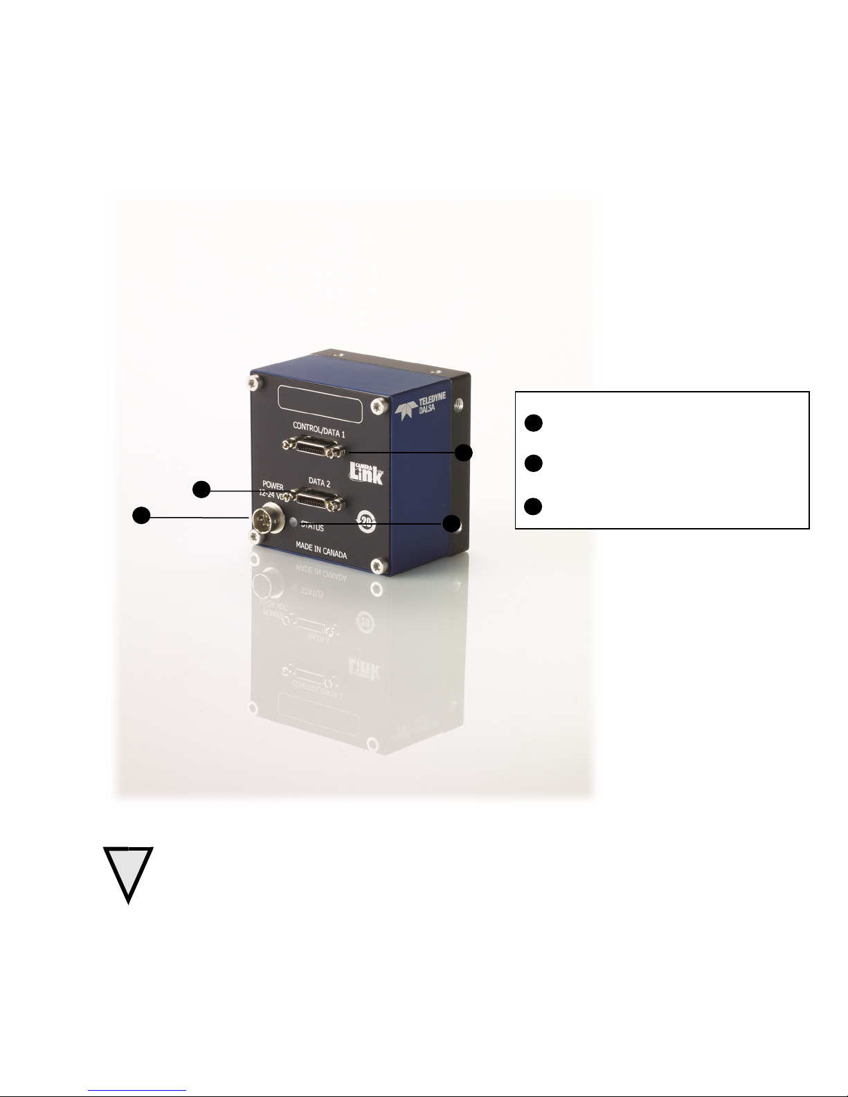
Step 2. Connect Data, Trigger, and Power Cables
Note: the u se of cabl es ty p es and l eng t hs other than those sp eci f ied m ay r esul t i n i ncr eased em i ssi o n or
d ecr eased i m mu n it y and per f or man ce of th e cam er a.
+12V to +24V DC Hirose 6-pin
Control & Data
Camera Link 26-pin SDR-26 connectors
Status
Diagnostic LED
C
Figure 12: Input and Output, trigger, and Power Connectors
WARNING! Grounding Instructions
Static electricity can damage electronic components. It’s critical that you dischar ge any stati c
el ectr ical char ge by touch i ng a g r ou n d ed sur face, su ch as t he m et al com p ut er chassi s, bef or e
hand l i n g t h e cam era har d w are.
Teledyne DALSA 03-032-20217-01
24 Piranha4 RGB + NIR / Mono Camera User's Manual
Camera
Right Angle
Channel Link
Camera
Right Angle
Channel Link
1 1 inner shield
1 1 inner shield
14
14
inner shield
14
14
inner shield
2
25
Y0- 2 25
X0-
15
12
Y0+
15
12
X0+ 3 24
Y1- 3 24
X1-
16
11
Y1+
16
11
X1+ 4 23
Y2- 4 23
X2-
17
10
Y2+
17
10
X2+
5
22
Ycl k-
5
22
Xcl k-
18 9 Ycl k+
18 9 Xcl k+
6
21
Y3- 6 21
X3-
19 8 Y3+
19 8 X3+ 7 20
100 oh m
7
20
Ser T C +
20 7 t er mi n at ed
20 7 Ser T C -
8
19
Z0- 8 19
Ser T F G -
21 6 Z 0+
21 6 Ser T F G +
9
18
Z1- 9 18
CC1-
22 5 Z 1+
22 5 CC1+
10
17
Z2-
10
17
CC2+
23 4 Z 2+
23 4 CC2-
11
16
Zcl k -
11
16
CC3-
24 3 Zcl k +
24 3 CC3+
12
15
Z3-
12
15
CC4+
25 2 Z 3+
25 2 CC4-
13
13
inner shield
13
13
inner shield
26
26
inner shield
26
26
inner shield
Signal
Configuration
CC2
Sp ar e
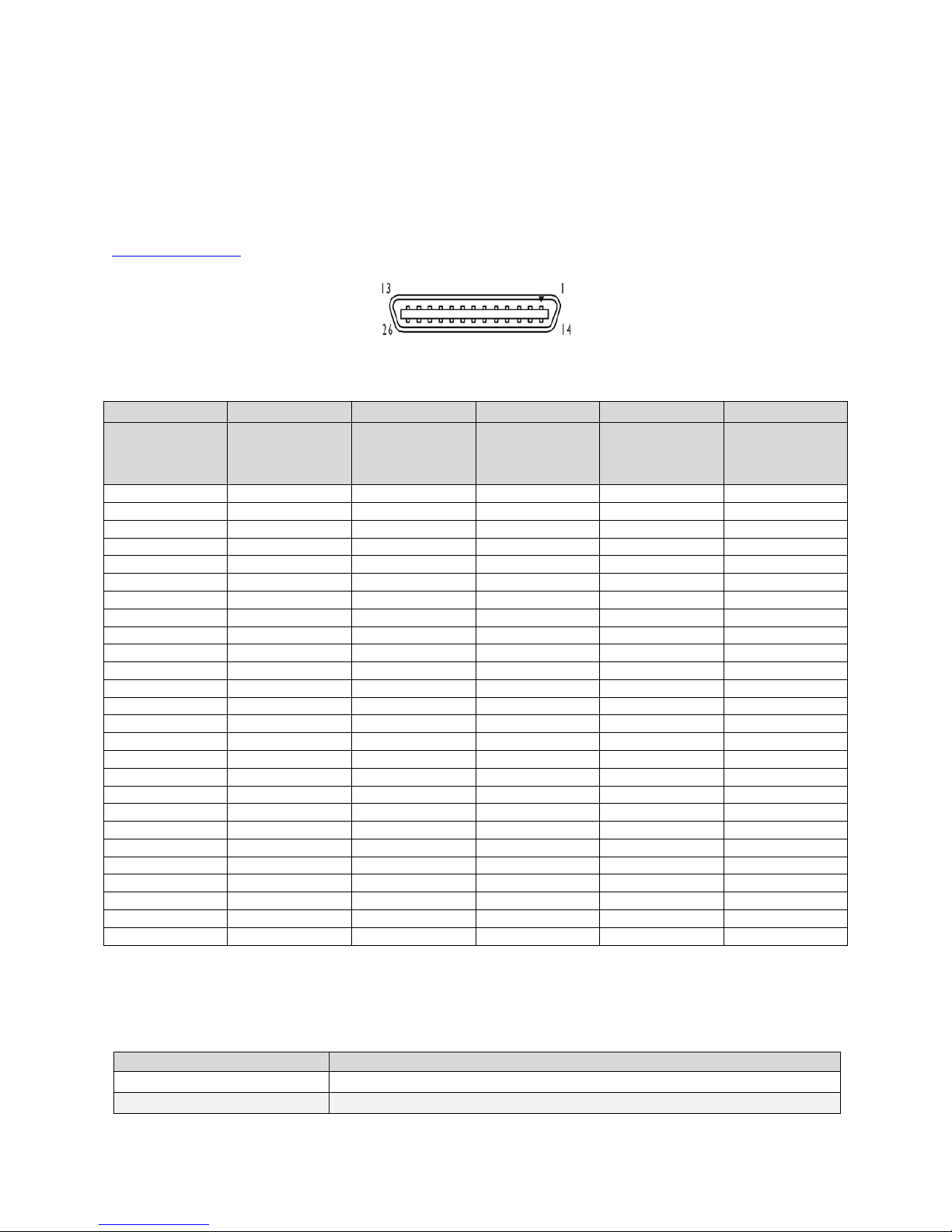
Data Connector: Camera Link
The cam era u ses tw o Camer a Li nk SD R26 cables transmitting the Cam era L i n k Base, M edi u m, Full, or
D eca configuration. The figure below shows the SDR26 Cam er a L i nk Con n ect or and t h e tabl es that f ol l ow
list the Camera Link configurations.
For d etai led i nf or m at i on on Cam era L i n k pl ease ref er t o t h e Cam er a L ink Road M ap av ai l abl e f rom th e
K n ow led g e Cen t er
Data 2 Control / Data 1
on t he Tel ed yne D A LSA W eb si te.
Figure 13. SDR26 Camera Link Connector
Connector
Frame Grabber
Connector
Signal
Connector
Frame Grabber
Connector
Signal
Note:
*Exterior Overshield is connected to the shells of the connectors on both ends. Unused pairs should be terminated in 100 ohms at
both ends of the cable. Inner shield is connected to signal ground inside camera
Camera Link Bit Definitions
CC1 EXSYN C
03-032-20217-01 Teledyne DALSA
Piranha4 RGB + NIR / Mono Camera User's Manual 25
CC4
Sp ar e
Red 1 D 0 .. D 7
Blue 1 D 0 .. D 7
Green
1
D 0 .. D 7
Red 2 D 0 .. D 7
Blue
2
D 0 .. D 7
Green
2
D 0 .. D 7
Red 3 D 0 .. D 7
Blue
3
D 0 .. D 7
Green
3
D 0 .. D 7
Red 4 D 0 .. D 7
Green
4
D 0 .. D 7
Red
2047 D 0
.. D 7
Blue
2047
D 0 .. D 7
Green
2047
D 0 .. D 7
Red
2048 D 0
.. D 7
Blue
2048
D 0 .. D 7
Green
2048
D 0 .. D 7
Blue 4 D 0 .. D 7
CL Port A
CL Port B
CL Port C
CL Clock
Line Valid
CC3 Direction
Table 6: Camera Control Configuration
For add i ti on al Camer a L i n k docum en t ati on r ef er t o t h e Tel ed y ne DA LSA W eb si te’ s
K n ow led ge Cent er
app l icat ion not es.
Camera Timing
N ot e: Information on setting up the camera’s A OI can be found here, A r ea o f In t erest ( A OI ) Setu p .
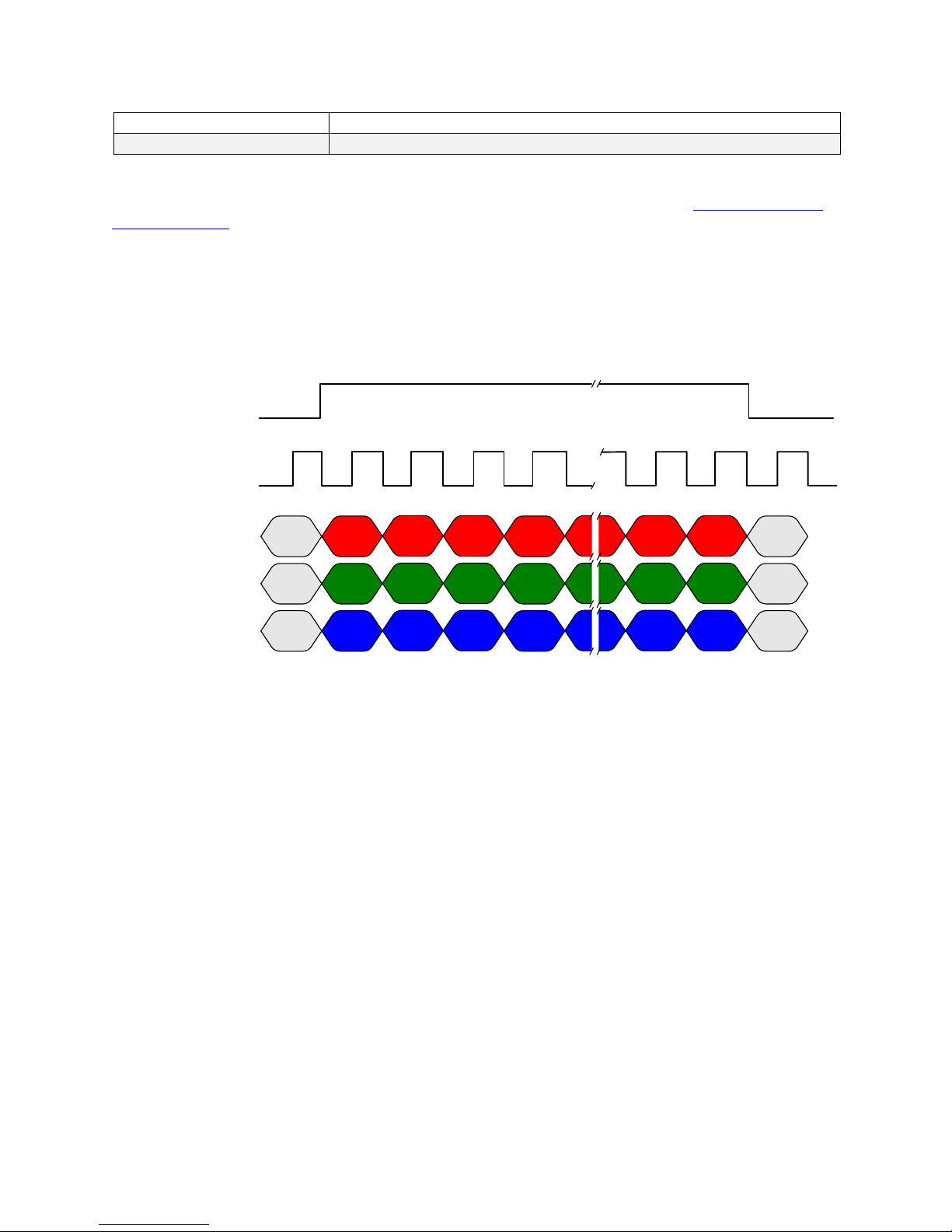
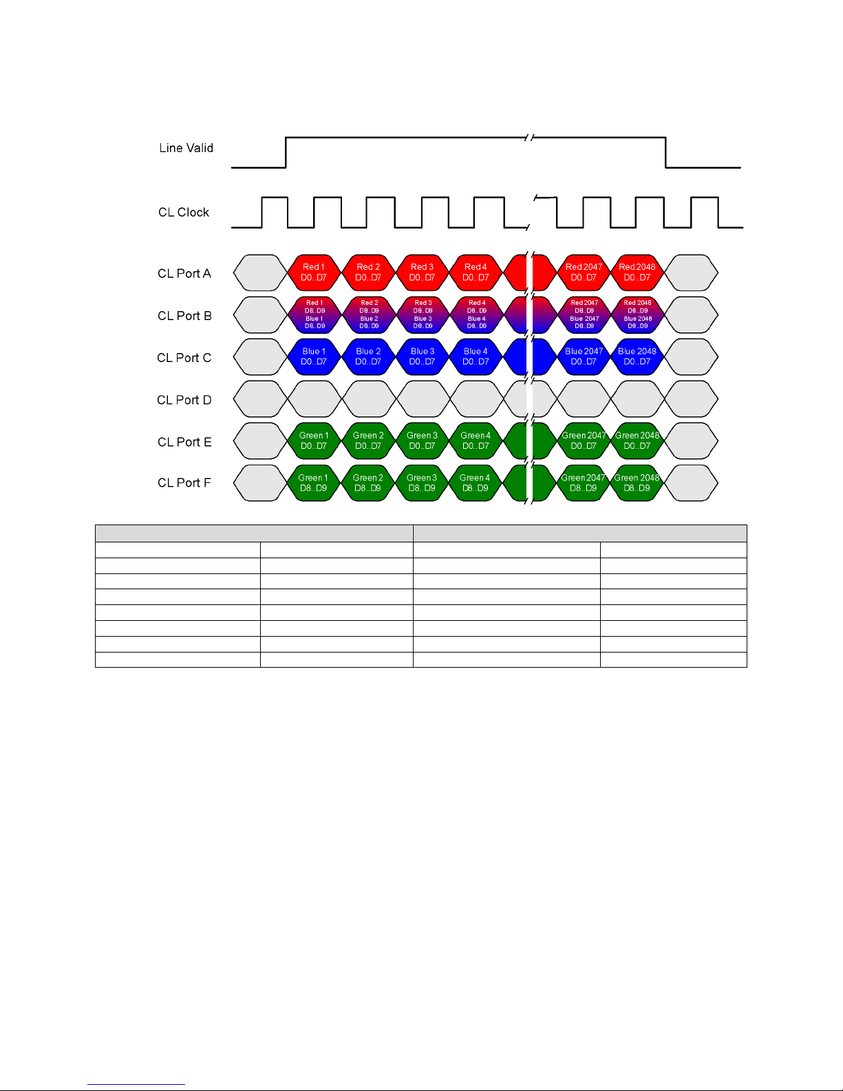
RGB 8 bit, CL base, maximum line rate 40 kHz, no AOI and 85 MHz CL clock
Th i s ti mi n g can be used f or appl i cat i on s t h at r eq u ir e li ne r at es onl y up to 40 kH z an d t h eref or e can u se
Cam era L i nk Base mod e w i t h onl y one cab l e.
The RGB output format is compatible w ith the Camera Link specification for Base RGB. Li ne r ates u p to
70 kH z can be ach i ev ed by usi n g t he A r ea o f In t erest ( A OI ) f eatu r e; w her e the sm al ler t he A OI , th e
gr eat er t he p ot en t i al l i n e r ate.
Teledyne DALSA 03-032-20217-01
26 Piranha4 RGB + NIR / Mono Camera User's Manual
Red 1
D0..D7
Blue 1
D0..D7
Green 1
D0..D7
Red 2
D0..D7
Blue 2
D0..D7
Green 2
D0..D7
Red 3
D0..D7
Blue 3
D0..D7
Green 3
D0..D7
Red 4
D0..D7
Green 4
D0..D7
Red 2047
D0..D7
Blue 2047
D0..D7
Green 2047
D0..D7
Red 2048
D0..D7
Blue 2048
D0..D7
Green 2048
D0..D7
Blue 4
D0..D7
CL Port A
CL Port B
CL Port C
CL Clock
Line Valid
Connector Data 1
Connector Data 2
CL Port A
Mono/IR 1
D0..D7
Mono/IR 2
D0..D7
Mono/IR 3
D0..D7
Mono/IR 4
D0..D7
Mono/IR
2047
D0..D7
Mono/IR
2048
D0..D7
CL Port C
CL Port B
Red
1
D 0 .. D 7
Blue
1
D 0 .. D 7
Green
1
D 0 .. D 7
Red
3
D 0 .. D 7
Blue 3 D 0 .. D 7
Green
3
D 0 .. D 7
Red
5
D 0 .. D 7
Blue 5 D 0 .. D 7
Green
5
D 0 .. D 7
Red
7
D 0 .. D 7
Green
7
D 0 .. D 7
Red
2045
D 0 .. D 7
Blue
2045 D 0
.. D 7
Green
2045
D 0 .. D 7
Red
2047
D 0 .. D 7
Blue
2047 D 0
.. D 7
Green
2047
D 0 .. D 7
Blue
7
D 0 .. D 7
CL Port A
CL Port C
CL Clock
Line Valid
Red 2 D 0 .. D 7
Blue
2
D 0 .. D 7
Green
2 D 0
.. D 7
Red
4
D 0 .. D 7
Blue
4
D 0 .. D 7
Green
4
D 0 .. D 7
Red
6
D 0 .. D 7
Blue
6
D 0 .. D 7
Green
6
D 0 .. D 7
Red 8 D 0 .. D 7
Green
8 D 0
.. D 7
Red
2046
D 0 .. D 7
Blue
2046
D 0 .. D 7
Green
2046
D 0 .. D 7
Red
2048
D 0 .. D 7
Blue
2048
D 0 .. D 7
Green
2048
D 0 .. D 7
Blue
8
D 0 .. D 7
CL Port D
CL Port F
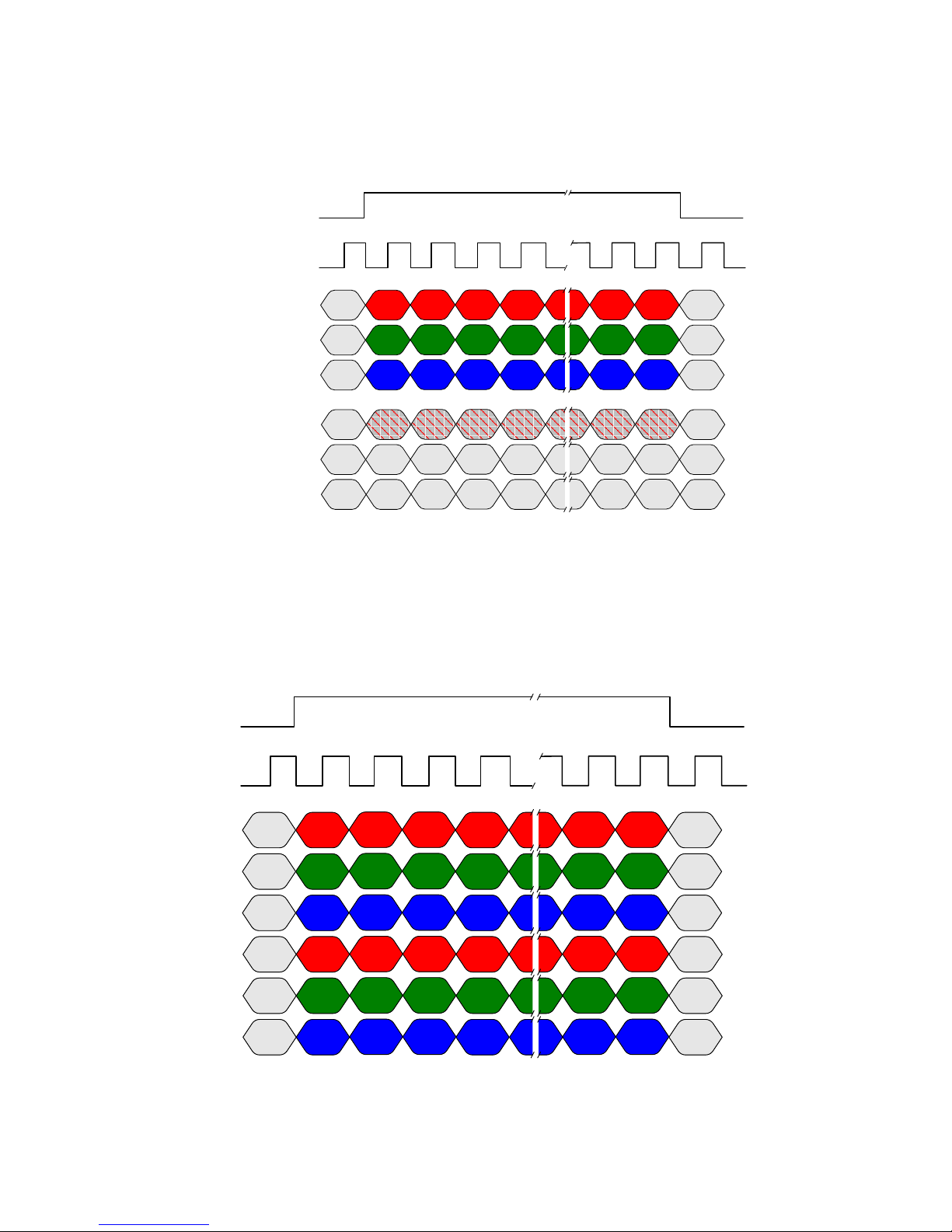
Dual base RGB 8 bit plus 8 bit monochrome, maximum line rate 40 kHz, no AOI and 85
MHz CL clock
Th i s ti mi n g can be used f or appl i cat i on s t h at r eq u ir e li ne r at es onl y up to 40 kH z an d t h eref or e can u se
Cam era L i nk D u al Base m od e w i t h o n l y one cabl e.
The RGB output format is compatible w ith the Camera Link specification for Base RGB. Li ne r ates u p to
70 kH z can be ach i eved by usi ng t he A r ea of I n t erest ( A OI ) f eatur e; w her e t he sm al l er t he A OI , t h e
gr eat er t he p ot en t i al l i n e r ate.
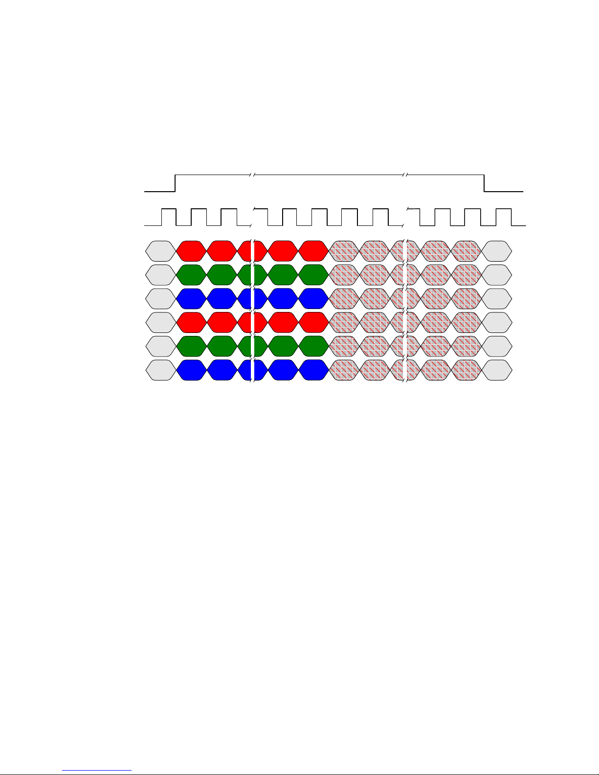
RGB 8 bit, CL Medium, maximum line rate 70 kHz, no AOI and 85 MHz CL clock
CL Port B
CL Port E
Th i s ti mi n g can be used f or appl i cat i on s t h at r eq u ir e li ne r at es up t o 40 kH z an d ther ef or e m ust u se
Cam era L i nk M edi u m m od e and t w o cabl es.
03-032-20217-01 Teledyne DALSA
Piranha4 RGB + NIR / Mono Camera User's Manual 27
Red 1
D0..D7
Blue 1
D0..D7
Green 1
D0..D7
Red 3
D0..D7
Blue 3
D0..D7
Green 3
D0..D7
Red 2045
D0..D7
Blue 2045
D0..D7
Green 2045
D0..D7
Red 2047
D0..D7
Blue 2047
D0..D7
Green 2047
D0..D7
CL Port A
CL Port B
CL Port C
CL Clock
Line Valid
Red 2
D0..D7
Blue 2
D0..D7
Green 2
D0..D7
Red 4
D0..D7
Blue 4
D0..D7
Green 4
D0..D7
Red 2046
D0..D7
Blue 2046
D0..D7
Green 2046
D0..D7
Red 2048
D0..D7
Blue 2048
D0..D7
Green 2048
D0..D7
CL Port D
CL Port E
CL Port F
Mono/IR 1
D0..D7
Mono/IR 2
D0..D7
Mono/IR 3
D0..D7
Mono/IR 4
D0..D7
Mono/IR 5
D0..D7
Mono/IR 6
D0..D7
Mono/IR 7
D0..D7
Mono/IR 8
D0..D7
Mono/IR 9
D0..D7
Mono/IR 10
D0..D7
Mono/IR 11
D0..D7
Mono/IR 12
D0..D7
Mono/IR
2037
D0..D7
Mono/IR
2038
D0..D7
Mono/IR
2039
D0..D7
Mono/IR
2040
D0..D7
Mono/IR
2041
D0..D7
Mono/IR
2042
D0..D7
Mono/IR
2043
D0..D7
Mono/IR
2044
D0..D7
Mono/IR
2045
D0..D7
Mono/IR
2046
D0..D7
Mono/IR
2047
D0..D7
Mono/IR
2048
D0..D7
The RGB output format is compatible w ith the Camera Link specification for M ed i u m RGB. Li ne r ates up
to 70 kH z can be achi eved by usi ng t he A r ea of Int er est (A OI ) f eatur e; w her e t he sm al l er t he A OI , t h e
gr eat er t he p ot en t i al l i n e r ate.
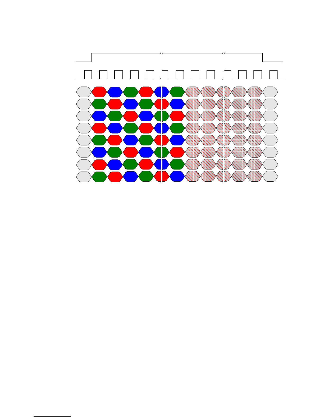
RGB plus monochrome 8 bit CL Medium, maximum line rate 62 kHz, no AOI and 85 MHz
CL clock
This timing can be used f or appl i cati ons th at r equ i re l in e r at es u p to 60 k H z and t her ef or e m ust u se
Cam era L i nk M edi u m m od e and t w o cabl es.
The RGB output format is not defined in the Cam er a Li nk speci f i cat ion D eca. The RGB format is such that
when using a Camera Link f ram e gr abber com pat i bl e w it h t he D eca f or mat con fi gu red for t he mono
stan dar d, t he R, G and t hen B p ix el s w il l b e w ri tt en sequ ent i al l y i n t o t h e f r am e gr abb er bu f f er . Thi s
p r ocess si mpl i f i es t he ex t r act i on of t he RGB d at a f r o m the f ram e g r abber bu ff er by the host application.
Li ne r at es u p t o 70 kH z can be achi eved b y u si ng th e A r ea o f In t erest ( A OI ) f eatu r e; w her e t he sm al ler t he
A OI , t he g r eat er th e pot ent i al l in e r at e.
Teledyne DALSA 03-032-20217-01
28 Piranha4 RGB + NIR / Mono Camera User's Manual
CL Port A
CL Port B
CL Port C
CL Clock
Line Valid
CL Port D
CL Port E
CL Port F
Mono/IR 1
D0..D7
Mono/IR 2
D0..D7
Mono/IR 3
D0..D7
Mono/IR 4
D0..D7
Mono/IR 5
D0..D7
Mono/IR 6
D0..D7
Mono/IR 9
D0..D7
Mono/IR 10
D0..D7
Mono/IR 11
D0..D7
Mono/IR 12
D0..D7
Mono/IR 13
D0..D7
Mono/IR 14
D0..D7
Mono/IR
2033
D0..D7
Mono/IR
2034
D0..D7
Mono/IR
2035
D0..D7
Mono/IR
2036
D0..D7
Mono/IR
2037
D0..D7
Mono/IR
2038
D0..D7
Mono/IR
2041
D0..D7
Mono/IR
2042
D0..D7
Mono/IR
2043
D0..D7
Mono/IR
2044
D0..D7
Mono/IR
2045
D0..D7
Mono/IR
2046
D0..D7
CL Port G
CL Port H
Mono/IR 7
D0..D7
Mono/IR 8
D0..D7
Mono/IR 15
D0..D7
Mono/IR 16
D0..D7
Mono/IR
2039
D0..D7
Mono/IR
2040
D0..D7
Mono/IR
2047
D0..D7
Mono/IR
2048
D0..D7
Red 1
D0..D7
Blue 1
D0..D7
Green 1
D0..D7
Red 2
D0..D7
Blue 2
D0..D7
Green 2
D0..D7
Red 3
D0..D7
Green 3
D0..D7
Blue 3
D0..D7
Red 4
D0..D7
Blue 4
D0..D7
Green 4
D0..D7
Red 5
D0..D7
Blue 5
D0..D7
Green 5
D0..D7
Red 6
D0..D7
Blue 6
D0..D7
Green 6
D0..D7
Red 7
D0..D7
Blue 7
D0..D7
Green 7
D0..D7
Red 8
D0..D7
Red 9
D0..D7
Green 9
D0..D7
Red 2047
D0..D7
Blue 2047
D0..D7
Green 2047
D0..D7
Red 2048
D0..D7
Blue 2048
D0..D7
Green 2048
D0..D7
Blue 2046
D0..D7
Green 2046
D0..D7
Blue 9
D0..D7
Red 10
D0..D7
Green 10
D0..D7
Blue 10
D0..D7
Red 11
D0..D7
Green 11
D0..D7
Blue 8
D0..D7
Green 8
D0..D7
RGB 8 bit CL Full plus monochrome 8 bit CL full
03-032-20217-01 Teledyne DALSA
Piranha4 RGB + NIR / Mono Camera User's Manual 29
D0
Red 8
D0
Gr een 8
D1
Red 9
D1
Gr een 9
D2
N/ A
D2
N/ A
D3
N/ A
D3
N/ A
D4
Bl ue 8
D4
N/ A
D5
Bl ue 9
D5
N/ A
D6
N/ A
D6
N/ A
D7
N/ A
D7
N/ A
RGB 10 bit CL Medium, maximum line rate 40 kHz, no AOI and 85 MHz CL clock
Port B Bit Assignments Port F Bit Assignments
Th i s ti mi n g can be used f or appl i cat i on s t h at r eq u ir e li ne r at es up t o 20 kH z an d ther ef or e m ust u se
Cam era L i nk M edi u m m od e and t w o cabl es.
The RGB output format is compatible w ith the Camera Link specification for M ed i u m RGB. Li ne r ates up
to 70 kH z can be achi eved by usi ng t he A r ea of Int er est (A OI ) f eatur e; w her e t he sm al l er t he A OI , t h e
gr eat er t he p ot en t i al l i n e r ate.
Teledyne DALSA 03-032-20217-01

30 Piranha4 RGB + NIR / Mono Camera User's Manual
D0
Red 8
D0
Gr een 8
D1
Red 9
D1
Gr een 9
D2
Red 10
D2
Gr een 10
D3
Red 11
D3
Gr een 11
D4
Bl ue 8
D4
N/ A
D5
Bl ue 9
D5
N/ A
D6
Bl ue 10
D6
N/ A
D7
Bl ue 11
D7
N/ A
RGB 12 bit CL Medium, maximum line rate 40 kHz, no AOI and 85 MHz CL clock
Port B Bit Assignments Port F Bit Assignments
Th i s ti mi n g can be used f or appl i cat i on s t h at r eq u ir e li ne r at es up t o 20 kH z an d ther ef or e m ust u se
Cam era L i nk M edi u m m od e and t w o cabl es.
The RGB output format is compatible w ith the Camera Link specification for M ed i u m RGB. Li ne r ates up
to 70 kH z can be ach iev ed by u si n g t he A r ea of I n t erest (A OI ) f eatu r e; w h er e th e smal l er th e A OI , t he
gr eat er t he p ot en t i al l i n e r ate.
03-032-20217-01 Teledyne DALSA

Piranha4 RGB + NIR / Mono Camera User's Manual 31
CL Port A
CL Port B
CL Port C
CL Clock
Line Valid
CL Port D
CL Port E
CL Port F
CL Port G
CL Port H
Red 1 D 0 .. D 7
Blue
1
D 0 .. D 7
Green
1
D 0 .. D 7
Red
1
D 8 .. D 11
CL Port I
CL Port K
Blue
1
D 8 .. D 11
Green
1
D 8 .. D 11
Green
2
D 8 .. D 11
Green
2
D 0 .. D 7
Blue
2
Red
D 0 .. D 7
Red
2
D 8 .. D 11
Blue
2
D 8 .. D 11
Red
D 0 .. D 7
Blue
3
D 0 .. D 7
Green
3
D 0 .. D 7
Red
3
D 8 .. D 11
Blue
3
D 8 .. D 11
Green
3
D 8 .. D 11
Green
4
D 8 .. D 11
Green
4
D 0 .. D 7
Blue
4
D
D
Red
D 0 .. D 7
Red
4
D 8 .. D 11
Blue 4 D 8 .. D 11
Red
D 0 .. D 7
Blue
2047
D 0 .. D 7
Green
2047
D 0 .. D 7
Red
2047
D 8 .. D 11
Blue
2047
D 8 .. D 11
Green
2047
D 8 .. D 11
Green
2048
D 8 .. D 11
Green
2048
D 0 .. D 7
Blue
2048
Red
D 0 .. D 7
Red
2047
D 8 .. D 11
Blue
2048 D 8
.. D 11
RGB 12 bit CL Deca, maximum line rate 70 kHz, no AOI and 85 MHz CL clock
3
2047
2
4
2048
Th i s ti mi n g can be used f or appl i cat i on s t h at r eq u ir e li ne r at es up t o 69 kH z an d ther ef or e m ust u se
Cam era L i nk D eca m od e and t w o cables.
The RGB output format is not defined in the Cam er a Li nk speci f i cat ion D eca. The RGB format is such that
when using a Cam era L i n k fr ame gr abb er comp at i bl e w i th t h e D eca f or mat con fi gu red for t he m on o
stan dar d, t he R, G and t hen B p ix el s w il l b e w ri tt en sequ ent i al l y i n t o t h e f r am e gr abb er bu f f er . Thi s
p r ocess si mpl i f i es t he ex t r act i on of t he RGB d at a f r o m the f ram e g r abber buffer by the host application.
Teledyne DALSA 03-032-20217-01
D 0 .. D 7
0 ..
7
D 0 .. D 7

32 Piranha4 RGB + NIR / Mono Camera User's Manual
Li ne r at es u p t o 70 kH z can be achi eved b y u si ng th e A r ea o f In t erest ( A OI ) f eatu r e; w her e t he sm al ler t he
A OI , t he g r eat er th e pot ent i al l in e r at e.
RGB plus monochrome / NIR 12 bit CL Deca, maximum line rate 70 kHz, no AOI and 85
MHz CL clock
Th i s ti mi n g can be used f or appl i cat i on s t h at r eq u ir e li ne r at es up t o 70 kH z an d ther ef or e m ust u se
Cam era L i nk D eca m od e and t w o cables.
The RGB output format is not defined in the Cam er a Li nk speci f i cat ion D eca. Th e RGB format is such that
w hen u si ng a C amer a Li nk f ram e gr abber com pat i bl e w it h the D eca f or mat con f igu r ed f or the m on o
stan dar d, t he R, G and t hen B p ix el s w il l b e w ri tt en sequ ent i al l y i n t o t h e f r am e gr abb er bu f f er . Thi s
p r ocess si mpl i f i es t he ex t r act i on of t he RGB data from the frame grabber buffer by the host appl icati on.
Li ne r at es u p t o 70 kH z can be achi eved b y u si ng th e A r ea o f In t erest ( A OI ) f eatu r e; w her e t he sm al ler t he
A OI , t he g r eat er th e pot ent i al l in e r at e.
03-032-20217-01 Teledyne DALSA

Piranha4 RGB + NIR / Mono Camera User's Manual 33
RGB BGR
RGB Vs BGR
The dat a ou t put can b e p r esented in two alternative formats: RGB or BGR. The p r evi o u sly ment i on ed
ou tp u t m od es ar e st il l v ali d in BGR m od e excep t the p osi ti on s of t he r ed an d th e bl ue ar e exch anged .
Green is still in its previously stated position.
Figure 14 RGB Vs BGR
Base and Medium Modes
1) Th e t ot al n u mber of pi xel s w i thi n each A OI mu st be a m u l t ip le of 8 and m ust be g r eater t han or
equ al t o 40.
2) In nor m al m o d e, t h e fi rst p i x el of each A OI (A OI l ef t ed ge) m ust h av e the l ocat i o n 8i, w her e i = 0,
1, 2 .., 511 (i .e. 8, 960 ar e al l ow ed, 12 i s not al low ed).
3) In m i r r or m od e, t he f i r st pi xel of each A OI (A OI ri gh t ed g e) m ust h av e t he l o cati on 8i + 7, w her e i
= 0,1,2 .., 511 (i .e. 7, 15, 4095 ar e al l ow ed, 8 i s no t al low ed).
Deca RGB Mode
1) The total number of pixels within each AOI must be a multiple of 40.
2) In nor m al m o d e, t h e fi rst p i x el of each A OI (A OI l ef t ed ge) m ust h av e the l ocat i o n 8i, w her e i = 0,
1, 2 .., 511 (i .e. 8, 960 ar e al l ow ed, 12 i s not al low ed).
3) In mirror mode, the first pix el of each A OI (A OI ri g h t ed g e) m ust h av e t he l ocati on 8i + 7, w her e i
= 0,1,2 .., 511 (i .e. 7, 15, 4095 ar e al l ow ed, 8 i s no t al low ed).
Teledyne DALSA 03-032-20217-01

34 Piranha4 RGB + NIR / Mono Camera User's Manual
10 m
Comp onent Express
PX4 and PX8
15 m
Comp onent Express
PX8
LVAL (high)
Outputting valid line
DVAL
N ot u sed
STROBE (r isi n g ed ge)
V al id d ata
FVA L
Set to 0
Camera Link cable quality and length
Th e m axi mu m al l ow abl e Cam er a Li n k cable l en g t h d epends on the quality of the cable used and the
Camer a L i nk str o b e f r equ ency . Cabl e qu al i ty d egr ades ov er t i me as t he cabl e is f lex ed . In addition, as t he
Camer a L i nk str o b e f r equ ency i s incr eased the maximum allowable cable length will decrease. We do not
guar ant ee good im agi ng p er form an ce w i th l ow qu ali t y cabl es of an y length. In general, we recommend
t h e u se of hi g h q u al i ty cabl es f or any cabl e lengt h .
The f ol l ow in g t abl e li st s som e r esu lt s achi eved usi n g t he cam er a and a sel ect i o n o f cabl es and f r ame
grabber s.
Distance Tested Cable Manufacture Frame grabber
Input Signals, Camera Link
The camera accepts control inputs through the Camera Link SD R2 6 F con nect or . Th e camer a shi ps i n
internal sync, and i nter nal ly p r ogr am med i nt egr ati on.
EXSYNC (Exposure Start)
Li ne r at e can be set i nt er nal l y usi ng t he GenICam features. The external control signal EXSYNC is
opt i onal and enabled through the user int er f ace. T h i s camer a uses t he f al l ing edge of EXSYN C to start the
exp osu r e per iod .
The EXSYN C si gn al t el l s t h e camer a w hen t o i nt egr ate the i mage, f ol low ed by th e r ead ou t. I t can be ei ther
an i n t ernal l y g ener ated si g n al by the camer a, or it can be su pp l ied ex t er n all y v i a t he ser i al int er face.
D ep end ing u p on t he m od e of op erat ion t h e hi gh t i m e of the EX SYN C si gnal can r epr esent th e i nt egr ati on
p er i od .
Note: The EXSYNC signal is measured at CC1 and will give a “ true” measurement (i.e. within the
m easu r em ent r esol ut i on of 25 ns) ev en thou gh t he cam er a w i l l on ly tr i gger at a m axi mu m o f 70 K H z.
Output Signals, Camera Link Clocking Signals
Th ese si g n al s ind icat e w hen d ata i s v al i d, al l ow i n g y ou t o cl ock the dat a f rom t h e cam era t o y ou r
acqu isi ti o n sy stem . These si g n al s ar e par t of the Cam era L i n k conf i gu r ati o n and y ou sh ou l d r ef er t o t he
Cam era L i nk I m pl em ent ati on Road M ap , avai labl e at our K n ow led g e Cen t er
t h ese si gn al s.
Clocking Signal Indicates
, for the standard location of
03-032-20217-01 Teledyne DALSA

Piranha4 RGB + NIR / Mono Camera User's Manual 35
!
1
6
5
4
3
2
1
+12 V t o +24 V D C
4
GN D
Gr een
Read y
!
Power Connector
WARNING: It is extremely important that you apply the appropriate voltages to your cam er a.
I n cor rect v ol tages m ay d am ag e t he cam era. I n pu t vol tage r eq u i r emen t : + 12 V DC t o +24 VDC,
2 A mps. Bef or e con n ect i ng pow er to t h e cam er a, t est al l p ow er su p pl ies.
Figure 15: 6-pin Hirose Circular Male Power Plug—Power Connector
Table 7. Power Plug Pinout
Pin Description Pin Description
2 +12 V to +24 V D C 5 GN D
3 +12 V to +24 V D C 6 GN D
The cam era r equi res a si ngl e v ol tage i np ut +12 V DC to + 24 VDC. T he cam er a meet s al l p er for m ance
specifications using standard switching power supplies, although well-r egu l ated l inear sup p l i es p r ov i de
optimum performance.
WARNING: When setting up the camera’s power supplies follow these guidelines:
• Apply the appropriate voltages.
• Pr o t ect t he cam er a w i th a 2 amp sl ow -blow fuse bet w een th e p ow er su p pl y an d th e cam er a.
• D o n ot u se th e sh i eld o n a multi-cond uctor cable for ground.
• K eep lead s as shor t as p ossi bl e in or d er t o r edu ce v o l t ag e d r op .
• U se h igh -qu al i t y sup p l i es i n or der to mi ni m i z e n oi se.
Note:
I f you r pow er sup pl y does n ot meet t hese r equ ir ement s, t h en t he camer a per for m ance sp eci f i cat i on s
ar e no t gu ar ant eed .
LEDs
The cam era i s equ i pped w i th an L ED on the back t o d i sp lay th e op er ati o n al st atu s of the camer a. T h e
t ab l e bel ow sum m ar i zes t h e op er ati n g st ates of t he cam er a and t he cor r esp on d i n g L ED st ates. When more
than one condition is active, the LED indicates the condition with the highest priority.
Color of Status LED Meaning
Off No pow er or h ar dw are mal f un ct i on
Blinking Green Powering up or cal i brating
Red Error. Ch eck Bi ST r egi ster f o r the sp eci fi c err or
Teledyne DALSA 03-032-20217-01

36 Piranha4 RGB + NIR / Mono Camera User's Manual
Step 3. Establish Camera Communication
Power on the camera
Turn on t h e camer a’ s power supply. You may have to wait while the cam er a r ead i es itself for operation.
The cam era m ust b oot f ul l y bef or e i t w i l l b e r ecogn i zed by the GU I —the L ED sh i n es gr een on ce th e
camer a is r ead y.
Connect to the frame grabber
1. Star t Sap er a CamEx p er t (or equ iv al en t Cam er a Li n k com p l i ant i n t er f ace) by doubl e cl i cki n g t he
d esk t op i con cr eated dur i ng t h e sof tw are inst al lati on.
2. CamEx p er t will search for installed Sapera devi ces. I n t he D evi ces l i st ar ea on t he l ef t sid e, t h e
connect ed fr ame grabber will be shown.
3. Select t he fr ame grabber d ev i ce by cl ick i ng o n t he nam e.
N ot e: The f ir st t i me y ou set up t he cam era y ou w il l n eed to est abl i sh a com mu ni cat ion l in k bet w een t he
camer a and fr ame gr abber . I n st r uct i ons ar e av ail abl e her e in A pp end i x E: Camer a, Fr ame Gr abber
Communication.
Connect to the camera
1. Start a new Sap er a Cam Exp er t ap p li cati on (or equivalent Camera Link compliant interface) by
double clicking the desktop icon created during the software installation.
2. I n t he D ev ices l ist ar ea on the l eft si de, sel ect t he C O M p or t bel o w the Cam er a Li nk l abel .
Check LED Status
If the camera is operating correctly at this point, the diagnostic LED w ill shine gr een.
Software Interface
A ll t he cam era f eatu r es can be cont r ol l ed t h r ou g h t he Cam Ex p ert i nt er face. For ex amp l e, u n d er t he
Sensor Control menu in the camera window you can control the l ine r ate an d exposur e ti mes.
03-032-20217-01 Teledyne DALSA

Piranha4 RGB + NIR / Mono Camera User's Manual 37
A note on th e CamExpert exampl es show n here: The exampl es show n for illustrati ve purposes an d may
At this point your host and camera system should be setup and you can verify the camera’s operation by
retrieving a test pattern and setting the cam er a’s t r i g g er and ex posur e ti m e.
Using Sapera CamExpert with Piranha4
Cameras
CamEx p er t i s t he cam er a in t erf aci n g t ool sup p or t ed by the Saper a l i br ar y . W hen used w i th a Pi r anh a4
camer a, Cam Exper t al l ow s a user to t est all cam er a op erat i ng m od es. A dd i ti on al l y Cam Ex p ert sav es t he
cam era user settings configuration to the camera or saves multiple configurations as individual camera
p ar amet er fi les on t he host sy stem ( * .ccf). Cam Exp er t can al so be u sed to u p gr ade t h e cam er a’s sof tw ar e.
An important component of CamExpert is its live acquisition display window which allows immediate
v er if i cati on of ti m i n g or con tr ol par amet ers w i t hou t t he n eed to r u n a sep ar at e acqu i si ti on p r ogr am.
For cont ex t sensi t i v e hel p, cl ick on t he button then click on a camera configuration parameter. A
short description of the configuration parameter will be show n in a popup. Click on the button to
op en t h e h elp f il e f or mor e d escr ip t iv e i n f or m ati on on Cam Exp er t.
The cen t ral sect i on of C am Exp ert pr ov id es access t o t he cam era f eatu r es and par amet er s.
Note: The av ail ab i li ty of t h e feat ur es i s dep end en t on the Cam Exp er t u ser set t i n g .
not enti rel y ref l ect the f eatures and p arameters avai l abl e from t h e camera m od el used i n your
application.
Teledyne DALSA 03-032-20217-01

38 Piranha4 RGB + NIR / Mono Camera User's Manual
CamExpert Panes
Figure 16. CamExpert’s Camera Control Window
03-032-20217-01 Teledyne DALSA

Piranha4 RGB + NIR / Mono Camera User's Manual 39
Figure 17. CamExpert GUI showing connected camera
The Cam Ex per t app li cat i on u ses pan es to simplify choosing and configuring camera files or acquisition
p ar ameter s for t he i nst al led d evi ce.
• D evi ce Sel ector p ane: V i ew and select fr o m any i nst al led Sap er a acqu i si t i on d ev i ce. Once a d ev i ce i s
selected CamExpert will only present acquisition parameters applicable to that device. Optionally
sel ect a cam er a fi l e incl ud ed w it h t he Saper a i n stal lat i on or sav ed by th e user.
• Paramet ers pan e: Allows viewing or changing all acquisition parameters supported by the
acqu isi ti o n d evi ce. Cam Exp er t d ispl ay s p ar amet er s onl y i f t h ose p aram eter s ar e su ppor t ed by the
installed device. This avoids confusion by eliminating parameter choi ces w hen t hey do n o t app l y t o
t h e h ard w ar e i n u se.
• D ispl ay pane: Prov i des a l i v e or si n g l e fr am e acqu i sit i on d isp l ay. Fr am e bu f fer p ar am eter s ar e sh ow n
in an information bar above the image w indow .
• Control Buttons: Th e D isp l ay p an e i ncl u d es Cam Ex p ert cont r ol bu tt on s. These ar e:
Acquisiti on control button:
Click once to start live grab, click again to stop.
Si ngl e f r ame grab:
Cl ick t o acqu i re on e f ram e f r om d evi ce.
Teledyne DALSA 03-032-20217-01

40 Piranha4 RGB + NIR / Mono Camera User's Manual
i m age t o virtually an y si ze and rat i o.
acquisition or in a still image.
Softw are trigger but ton:
With the I/ O control parameters set to Trigger Enabled / Software
Tri gger type, click to send a single softw are tri gger command.
Cam Expert di spl ay control s:
(these do not modify the frame buffer data)
Stretch image to fit, set image display to original si z e, or zoo m t he
H i stogram / Pr of i l e tool:
Select to view a histogram or line/ column profile during live
• Output M essage pane: D i sp lay s messages f rom Cam Exp er t o r th e d evi ce d r i v er .
Review a Test Image
The cam era i s now read y t o r etr iev e a test p at t ern . Sel ec t I mage Format Contr ol > Test Pattern and
ch oose one of the following available t est i mages.
0. Off: Sen sor V i d eo
1. Gr ey Ram p
2. Ram p
Pixels: {1, 2, 3…}
Red V alu e: {0, 1, 2…}
Gr een V al u e: {102, 103, 104…}
Bl ue V al ue: {204, 205, 206…}
V al ues roll ov er at 255.
At this point you ar e read y to st art oper at i n g t h e cam era i n or der t o acqu i re i m ages, set cam er a f u nct i on s,
and sav e sett in g s.
03-032-20217-01 Teledyne DALSA

Piranha4 RGB + NIR / Mono Camera User's Manual 41
4. Camera Operation
Factory Settings
The cam er a ships and powers up for the first time w i th the following factory sett i ngs:
• Camer a L i nk M edi um , 8 bit pixels, 85 M H z
• I n t er n al t r igger , l in e r at e 10 k H z
• I n t er n al ex p osu re con t rol , ex p osu r e ti me 30.5 µ s
• Flat field disab l ed
• U ser coef f i ci ent s set t o 1x
• Offset 0, Sy s t em Gai n 1x
• W h i te bal anced gai ns al l set to 1x
• Color corr ection, n ot ap pl i ed
• Co r r ect ed u si n g an 80 mm l ens and a magnification of 0.8
Check Camera and Sensor Information
Cam era and sen sor i nf or mat i on can be r et ri ev ed v i a a con t rol l ing ap p li cati on —f or exam pl e, t h e
CamEx p er t GU I sh ow n in the fol l ow ing exam p l es. Par ameter s such as cam era m od el , f i rm w ar e v er sion ,
sensor ch ar act er i st ics, et c. ar e r ead t o u ni qu el y i d ent i f y th e con n ected d evi ce.
The cam era i nf or m at i on p ar am eter s ar e g r ou ped t og et her as m emb er s of th e Cam er a I nf or mat ion set .
Teledyne DALSA 03-032-20217-01

42 Piranha4 RGB + NIR / Mono Camera User's Manual
Figure 18. CamExpert’s Camera Information Window
Verify Temperature and Voltage
To d eter mi ne the v ol tage and tem p erat ur e at t he cam er a, u se t he Ref resh Voltage and Ref resh
Temperatu re f eat ur es found in the C amera Information set .
The t em per atu r e retu r ned i s t he in t ern al t emp er atur e i n d egr ees Cel si us. Fo r pr op er op er at i on, t hi s v al ue
shoul d n ot ex ceed 80 °C. I f th e cam er a exceed s the d esi gn ated tem p erat ur e i t w i l l stop imaging and the
LED will turn red. Once y ou hav e d iagnosed and r emed i ed t he i ssue u se t he reset camer a function.
The v o l t ag e d i sp l ay ed i s th e camer a’ s i np ut v ol t age.
Note: The v ol tag e m easur ement f eatu r e of th e cam er a pr ov id es resu l ts ty p ical ly w i t hi n 1%. This
m easu r em ent can be u sed t o set the ap pl i ed v o l t ag e t o t he cam er a.
03-032-20217-01 Teledyne DALSA

Piranha4 RGB + NIR / Mono Camera User's Manual 43
cu r rent set .
Saving and Restoring Camera Settings
The p ar amet er s u sed to sel ect , l oad and sav e u ser set s ar e g r ou ped t oget her un d er t h e Cam er a
Information set of f eatur es. Th er e are 8 u ser set s av ai l abl e and o n e f act or y set .
Camera Information
Parameter Choices
U ser Set D efau l t Sel ect o r Select t he cam er a param et er s to load when the camer a is r eset or pow ered up as t h e
Fact or y set, or as U ser Set 1 to 8.
Selecting the set from the list automatically saves it as the default set.
U ser Set Sel ect o r Sel ect th e Fact or y or User set to Save or L oad.
-Fact or y Set
-U ser Set 1 t o 8.
U ser Set L oad Load the set speci fi ed by User Se t Sel ector to t h e cam er a and m ak e i t t h e acti v e /
U ser Set Sav e Save t h e cu rr en t set as sel ected u ser set.
Description of the Camera Settings
The cam er a op er at es i n on e of thr ee sett i ngs:
1. Cur ren t sessi o n .
2. User sett i ng .
3. Factory setting (r ead -only).
4. Default setting.
The cur ren t sett i ng s can be sav ed (t h er eby b ecom i n g t he u ser sett i ng ) u sin g t he U ser Set Save p ar am eter .
A pr evi ou sl y sav ed u ser set ti ng ( U ser Set 1 to 8) or the factory settings can be r estor ed usi ng t he U ser Set
Select or and U ser Set L oad par am et ers.
Ei ther the Fact or y or on e of the U ser sett i n gs can be sav ed as t h e Def aul t Sett i ng by sel ecti ng th e set i n t he
U ser Set D efau lt Sel ector . Th e ch osen set aut om ati cal ly sav es as t he d efau l t set t in g an d i s t he set load ed
when the cam er a i s r eset o r powered up.
The r el ati o n shi p bet w een t hese t hr ee set ti ng s i s il lu st r at ed in Fi g u re 18. Rel ati on sh ip b et w een th e Cam er a
Settings:
Teledyne DALSA 03-032-20217-01

44 Piranha4 RGB + NIR / Mono Camera User's Manual
Figure 19. Relationship between the Camera Settings
Active Settings for Current Session
The act i v e sett i ng f or the cu r r ent sessi on i s the set of configurations t h at ar e operating while t h e camer a is
currently running, including all unsaved chan g es y ou hav e mad e to t h e set ti ngs b ef or e sav i ng t hem.
These act i v e set ti n gs ar e stor ed i n the cam er a’ s volatile m em or y an d will be lost and cannot be r est or ed if
t h e cam er a r eset s or if the cam er a is p ow er ed dow n or l oses p ow er.
To sav e t hese set t i n gs f or r euse t h e nex t t i me y ou p ow er u p or reset t he cam er a, or to protect against
l o si ng t hem i n t he case o f pow er l oss, you must save the current settings u si n g t he U ser Set Save
p ar am et er . Once sav ed, t h e cu r r ent setti ngs becom e th e sel ect ed User Set.
User Setting
The u ser sett i ng i s th e sav ed set of cam er a configur ations th at you can cu st om i ze, resav e, and rest o r e. By
d ef au l t t h e user set ti ngs ar e shi p ped w i t h t h e sam e set ti n gs as t he f act or y set .
The command User Set Save sav es th e cu r r ent set ti n gs to non-volatile memory as a U ser Set . Th e cam er a
aut om at ical l y restor es t h e last saved user sett i ng s w hen it pow ers up.
To r estor e th e l ast sav ed u ser sett i ng s, sel ect t he U ser Set par amet er y ou w an t to r est or e and t hen sel ect
t h e U ser Set Load p aram eter .
03-032-20217-01 Teledyne DALSA

Piranha4 RGB + NIR / Mono Camera User's Manual 45
Factory Settings
The factory setting is the cam er a sett i ng s t hat w er e sh i pp ed w it h the camer a and which loaded during the
cam era’ s fi r st pow er-up. To load or restore the original factory settings, at any time, sel ect t h e Factory
Setting par amet er an d th en select the U ser Set L oad p ar amet er .
Note: By default, the user settings are set to the factory settings.
Default Setting
Ei ther the Fact or y or on e of the U ser sett i n gs can be used as the D ef aul t Set ti ng b y select i ng t he set i n th e
U ser Set D efau lt Sel ector . Th e ch osen set aut om ati cal ly beco m es the d ef aul t set t i n g an d i s the set l oad ed
w hen t h e cam er a i s reset of pow ered up .
Camera Link Configuration
Name Taps SPF* Cables
Base 3 8, 10, 12 1
Du al Base 4 8 2
M edi u m 6 8, 10, 12 2
Ful l 8 8 2
D eca 10 8, 12 2
*Set Pi xel For mat ( n u mber of bi t s per pi x el)
Trigger Modes
The cam era’s i mage exp osu r es are initiated by a tri gger event . Th e t ri gger even t i s ei th er a pr ogr am m abl e
internal signal u sed in f r ee ru n n i ng m od e, an ex ter n al i np ut u sed f or synch r oni zi ng ex p osu res t o ex t er n al
triggers, or a programmed function cal l message by the controlli ng computer. These t ri gger i n g m od es ar e
d escr ibed bel ow .
• I nternal tri gger (trigger disabled): The cam era f r ee-running mode has a programmable internal
timer for li ne r at e and a programmable exposure period.
• Extern al tri gger (trigger enabl ed): Exp o su r es are co n t r ol led by an ext er nal tr igger si gn al . The
ext er nal tr igger si gn al i s the Camera Link contr ol l i ne CC1.
Exposure Controls
Exposure Control modes define the method and timing of how to control the sensor integration period.
The integration period is the amount of time the sensor is exposed to incoming light before the video
frame data is transmitted to the controlling computer.
• Exposure control is defined as the start of exposure and exposure duration.
• The start of exposure can be an internal timer signal (free-running mode) or an external trigger
signal.
• The exposure duration can be programmable (such as the case of an internal timer) or controlled by the
external trigger pulse width.
The cam er a can gr ab i mages i n on e of t h r ee w ays. You det erm i ne the thr ee im agi ng m od es usi ng a
combi nation of t he Ex posu r e M od e par am et ers (i ncl u d i ng I / O p ar amet er s), Exp osu r e Ti me an d L i ne Rat e
par ameters.
Teledyne DALSA 03-032-20217-01

46 Piranha4 RGB + NIR / Mono Camera User's Manual
pulse
Exposur e Mode
Set t he op er at i o n m od e f or the cam er a’ s exp osu r e.
enabl ed.
Tri gger Width
Ti med
Exposure Ti m e Sel ector
Exposure Time
Sets t he exp osu r e ti me (i n m i cr osecon d s). Exposure M od e feat ur e m ust be set
Description Line Rate Exposure Time Trigger Source
(Sync)
Internal line r at e and ex p o su re ti m e I n t er n al , pr ogr amm abl e Int er n al pr ogram m abl e Internal
Ex t er nal line rat e an d exp osu r e ti me Control l ed by EXSYN C
Ex t er nal (EXSYN C) Ex t er nal
EXSYNC pulse controlling the line
r at e. Pr ogr am med exp o su r e ti me
Th e p aram et er s u sed t o sel ect t he i m agi n g mod es—t r i gger sou rces ( sy nc) , ex p osu re t i me, an d li ne r ate—
ar e gr ou ped t og et her as t he Cam era Controls.
Parameter Description
Trigger Width or Ti med. Tr i gger W i d th i s on ly av ai labl e w hen Tr i g ger M od e is
U ses t he w id th of t he cu rr ent l i n e t ri gger si gn al pu l se to cont r ol t he ex p osu re
d u r ati on.
The exp osu r e dur at i on t i me i s set usi ng t he Exp o su re Ti m e f eat ur e and t he
exp o su re st ar t s w i t h t h e Line Start event.
I n t er n all y gener at ed . A ll ow s for an i nd epen dent exp osu re t i me to be ap p l i ed t o
each individual color.
t o Ti m ed
Control l ed by EXSYN C
pulse
Figure 20. Exposure controls
Camera Controls
I n t er n al pr ogr amm able Ext ern al
03-032-20217-01 Teledyne DALSA

Piranha4 RGB + NIR / Mono Camera User's Manual 47
Exposure Modes in Detail
1. Internally Programmable Line rate and Internally Programmable Exposure Time (Default)
L i ne r ate is the dominant factor w hen adjusting the l i n e rat e or ex posur e ti m e. W hen set t i n g t he l i ne r at e
exp osu r e ti me w i l l d ecr ease, i f necessar y, t o accom m o d ate the new li ne r ate. When adjusting the
exp osu r e ti me th e r ang e i s li m i t ed by t he l i n e r ate.
: The camera will not set line per i od s sho r ter than t he r eadout period.
Note
GenI Cam par am eters to set:
I / O Cont rol s > T ri gger M ode > Of f
2. External Line Rate, Programmable Exposure Time
I n t hi s mod e, th e l i n e rat e is set ex t er n al l y w i t h t h e f al l in g ed ge of EXSYN C gener at i ng t h e r isi n g ed ge of
a p r ogr amm abl e exp o su re t im e.
GenI Cam par am eters to set:
• I / O Control s > T ri gger M ode > On
• Sensor Control > Exposure M ode > Timed
3. External Line Rate and External Exposure Time (Trigger Width)
In thi s mod e, EXSYN C sets both t he l in e p er iod and th e exp osu re t i me. T h e r isi n g ed ge o f EXSYN C m ar k s
t h e b egi nni ng of the ex p osu re an d th e f al l ing ed g e i ni t i ates r ead ou t. N ot e:
GenI Cam par am eters to set :
• I / O Control s > T ri gger M ode > On
• Sensor Control > Exposure M ode > Trigger Width
Warning! When r un ni n g ex t er n al li ne r at e and ext er n al ex posu r e t im e, t h e l ine r ate m ust n ot exceed 1 /
(exp osu r e ti me + 1, 000 ns). U nd er these con d i t i ons t he exposu r e ti me w il l becom e i n d eter mi nat e and
r esu l t in i m ag e ar tef acts. Thi s is n ot t he case w hen ru nn in g i nt er nal exp osu r e co n t r ol .
Teledyne DALSA 03-032-20217-01

48 Piranha4 RGB + NIR / Mono Camera User's Manual
1. External Trigger Off, Internal Exposure Control
Free running, not synchronized to an external signal
Programmable Line Time
Programmable Exposure
1
Sensor
Readout
2
27.5us
Sensor
Readout
2
>1.5us
Programmable Exposure
1
Programmable Exposure
1
Sensor
Readout
2
LVAL
2. External Trigger On, Internal Exposure Control
CC1 Falling edge triggers start of internal exposure
3
Line Time
Programmable Exposure
1
Sensor
Readout
2
27.5us
Sensor
Readout
2
>1.5us
Programmable Exposure
1
Programmable Exposure
1
Sensor
Readout
2
LVAL
CC1
3. External Trigger On, External Exposure Control
CC1 Falling edge triggers start of exposure
CC1 high duration sets the exposure time
Line Time
Exposure = X
1
Sensor
Readout
2
27.5us
Sensor
Readout
2
>1.5us
Sensor
Readout
2
LVAL
CC1
Exposure = X
2
X
1
X
2
Exposure = X
3
X
3
Notes:
1. Exposure time > 7 micro-seconds
2. Sensor Readout time = 14 micro-seconds
3. One additional falling edge during exposure is latched
Figure 21. Exposure Modes
03-032-20217-01 Teledyne DALSA

Piranha4 RGB + NIR / Mono Camera User's Manual 49
Color Exposure Time Guidelines
The cam er a has no li m it at ions on t he com bi nat ions of the exp osur e ti mes av ail abl e for each col or excep t
the maximum of 3 ms and the minimum of 7μs exposu re t im es. Oper ating the camera with the conditions
stated below will give t he u ser op ti mu m i m age p er f or mance. Op er at i n g t he cam er a bey on d th e st ated
l i mi t s may b e p ossi bl e but m ay al so compromise image quality.
Tri-Linear Ideal Operating Conditions
For op t im u m i mage p er for mance al l of t he f ol l ow in g m ust be t r ue
1. Bl ue ≥ Red by 1μs
2. Bl ue ≥ Gr een b y 1μs or Green ≥ Blu e by 1μs
3. Red ≥ Gr een b y 1μs or Green ≥ Red by 1μs
Quad-Linear Ideal Operating Conditions
For op t im u m i mage p er for mance al l of t he f ol l ow in g m ust be t r ue
1. Bl ue ≥ Red by 1μs
2. Gr een ≥ Mono by 1μs
3. Bl ue ≥ Gr een b y 1μs or Green ≥ Blu e by 1μs
4. Bl ue ≥ Mono by 1μs or M ono ≥ Bl ue by 1μs
5. Red ≥ Gr een b y 1μs or Green ≥ Red by 1μs
6. Red ≥ M ono by 1μs or M ono ≥ Red by 1μs
Set Line Rate
To set the camer a’ s l ine r ate u se t he l i ne r at e p aram eter , p ar t of the Sensor Con t rol s set. Th is f eat u r e can
only be used when the camera is in Intern al m od e—t hat i s, w hen t h e st art l i n e tr i gger i s di sabl ed (Tr i gger
Mode Off).
Note: Th e l ine r ate m u st be l ess than 1 / (Ex p osu r e tim e + 1500ns). Ent eri n g a v alu e t hat vi ol ates thi s
con d it i on w il l r et urn an er ror (“ Inv ali d Par am eter” ). You must ad ju st th ese t w o p aram eter s in t he cor rect
sequence to maintain this condition.
I f th e ex t ern al li ne r ate exceed s 70 k H z the camera will continue to output data at its maximum line rate
of 70 k H z. Though no i mag e ar tefact s associ at ed w it h ov er-speed will occu r, y ou m ay not i ce th at under
ov er -sp eed con d i t i on s t he i m age w i l l ap p ear com pr essed an d th e ap par ent d i st ance t rav el l ed w i l l be
r ed uced .
Teledyne DALSA 03-032-20217-01

50 Piranha4 RGB + NIR / Mono Camera User's Manual
L i ne Rat e (i n H z)
Cam era l i ne r at e i n a r ange f r om 0 H z to 70 K H z.
Base
40 kH z
M ed i um
41 kHz
Ful l
55 kHz
D eca
68.5 kH z (D eca RGB8)
Bl ack L ev el
Apply a digital addition after an FPN cor r ecti on: ± 1/ 8 of the av ai l abl e r an ge of
Gai n
Set the gain as an amplification factor applied to the video signal acr oss al l
pixels: 1x to 10x.
Camera Control
Parameter Description
Thi s feat u re i s only available w hen the camera i s in Internal Mode—
line t r i g g er i s d isab l ed (Tr i gger M od e of f).
Line Rates
Camera Link Configuration Maximum Line Rate
Note: 70 kHz line rate can be achieved using AOI mode for all Camera Link Mode. For more information, see Area of Interest
(AOI) Setup.
Set Exposure Time
To set the camer a’ s ex p osu re t im e, u se t he Exposure Ti me p ar ameter —a member of the Sensor Control s
set . This feature is only available when the Exposure M ode p aram eter is set t o T imed. Th e al low abl e
exp osu r e range i s fr om 7 µs to 3,000 µs, dependent on the value of the i nternal line rate.
GenI Cam par am eters:
Sensor Controls > Exposure Time (Timed Exposure M ode) > 8 µs to 3,000 µs.
Control Gain and Black Level
The camer as provide gai n and bl ack l ev el ad j u st ments in the digital domai n for the CM OS sensor . The
gai n and bl ack lev el con t r ol s can mak e small compensati ons t o the acqui si ti on in sit u at i ons w her e
lighting v ar i es and the l en s iris cannot be easi l y ad ju sted . The u ser can ev al uate gain and bl ack lev el by
u si ng CamExp er t.
The p ar amet er s t h at co n t rol gai n and b l ack l evel ar e gr ou ped t og et her i n t he Sensor Cont r ol s set.
Sensor Controls
-32 to +31 in 8-bi t m od e, -128 t o +127 i n 10-bit mode, and -512 t o +511 i n 12-bit
m od e.
Set Image Size
To set the h ei gh t of th e im age, an d ther ef or e th e nu mb er of l ines t o scan, u se the p ar amet er s gr ou p ed
u n d er t he I mage For mat C on t rol set .
03-032-20217-01 Teledyne DALSA

Piranha4 RGB + NIR / Mono Camera User's Manual 51
Control the size of the transmitted image
Width
Width of the image.
H ei g h t
Hei gh t of the i mage i n l i nes.
Pixel For m at
8 b i t d ept h t o Cam er a Link.
Test I mage Select o r
Select an i n t ern al test i mag e:
Co n t r ol the bau d r ate u sed by t h e
Baud Rate
9600 (f act or y d ef au lt )
N um b er of b i ts p er char act er used in t h e
serial port
Dat a Si ze
8
Parity of the serial port
Par i ty
N one
N um b er of st op bi ts p er char act er used
i n the ser i al p or t
N umber of Stop
Bi t s
1
Image Format Control
Off
Color Ramp
Gr ey Ram p
Set Baud Rate
The bau d r at e sets t h e speed ( i n bi ts p er second —b p s) of the seri al comm u ni cati on p or t and i s avai labl e as
p ar t of the Seri al Port Control parameters.
Serial Port Control
camer a’s seri al por t
Pixel Format
Action Parameter Options
19200
57600
115200
230400*
460800*
921600*
Note: During connection Cam Ex per t
aut om at ical l y sets t h e cam era t o
maximum allowable baud.
*Y our system r eq u i res a Px 8 f ram e
gr ab ber to ach i eve t h ese b aud rat es.
U se t he Pi x el For mat feat ur e, found in the Image Format Control set , t o sel ect t h e for m at of the p i xel to
use during image acquisition.
Teledyne DALSA 03-032-20217-01

52 Piranha4 RGB + NIR / Mono Camera User's Manual
Pixel Format
RGB8, RGB10, RGB12
Internal
extern al
Scan D ir ect i on
Read the current direction.
Rev erseX
Off: All pixels are read out from left to right.
Cam era Reset
Reset s t he cam era an d p u ts i n th e d efau l t setti ngs, i ncl ud i ng a 9600 bau d
r ate.
Image Format Control
Parameter Description
Camera Direction Control
Found in the I / O Contr ol > Direction Control set of feat u r es.
Direction Control
Parameter Description
Sen so r Sca n D i r ect i on Thi s com m and let s you sel ect t h e
direction control. U se t hi s f eat u re t o accom m od at e obj ect
direction change on a web and to m o u nt t h e cam er a
"upside down."
or
Pixel Readout Direction (Mirroring Mode)
Set the tap readout from left to right or from right to left. This feature is especially useful if you want to
m ou n t t h e cam er a “ upsi de d ow n.”
Image Format Control
Parameter Description
On: All pixels are read out from right to left.
Resetting the Camera
The f eat ur e Camera R eset, part of the Transport L ayer set , reset s th e cam er a. Th e cam er a reset s w i t h t h e
default settings, including a b aud rat e of 9600.
Camera Information
Parameter Description
03-032-20217-01 Teledyne DALSA

Piranha4 RGB + NIR / Mono Camera User's Manual 53
Video
Gain
Output
Video
Digital Processing (color)
-
+
Offset
BlackLevel
(ssb)
x
Gain
(ssg 3)
-
Calibrate FPN
flatfieldCalibrationFPN
(ccf)
xR
xG xB
White
Balancing
BalanceWhiteAuto
(bwa,
ssg(0,1,2))
X X X X
X X X X
X X X X
Color
Correction
colorCorrectionMode
(ctv)
x
Calibrate
PRNU
flatfieldCorrectionMode
flatfieldCalibrationPRNU
flatfieldCorrectionAlgorithm
(cpa,ffm)
Calibrating the Camera
Important Note: t o en su r e best resu l ts, t h e con d it i ons u n der w hi ch y ou cal i br ate t he cam er a (e.g.
t em per atu re an d i l lu m i n at ion) shoul d be as cl ose t o t he act u al o p erat i n g co n d iti on s as possi b l e.
Overview
The following diagram and accompanying descri ption explai n the cameras signal processing chain. Each
el em ent sh o w n, w it h th e ex cept i on of col or int erp o l ati on , i s user p r ogr am m abl e.
Digital Processing
1. Fi x ed patt er n n oi se (FPN ) cal i br ati on i s used t o su bt r act an y resid u al d ark l evel t hat may occu r in
the application.
2. Photo response non uniformity (PRNU) calibration is used to correct for variations in the
illumination intensity and / or lens vignetting. When performed, this calibration will cause the
cam era t o h av e a fl at r esponse t o a w hi t e tar get i n the f iel d of v i ew . The ou t pu t tar get v alu e f or
PRN U cal ibr at ion can be set b y th e user .
3. The w hi te bal anci ng gai ns ar e used set th e r ed , gr een and b l ue r espo n se t o eq u al v alu es w i t h a
w hi t e t ar get i n t he f iel d of v iew . T h e w hi t e bal ance gai ns can be i n di vi du al l y set by t he u ser , but
Teledyne DALSA 03-032-20217-01
Figure 22: Flat Field Calibration in CamExpert
Figure 23: Camera Calibration Process.

54 Piranha4 RGB + NIR / Mono Camera User's Manual
w i l l be o v err i dd en b y the cam er a w hen t h e cam er a performs PRN U cali bration or w hite
balanci ng commands.
4. Co l or cor rect ion i s av ai l abl e for th ose u ser s th at n eed to com p ensat e f or t h e sp ectr al t r an smi ssion
char acter i sti cs of t h e sen sor s col or f il t er s an d t h e cu st om ers l igh t sou rce. Thi s can be ach i eved b y
imaging the Gr etag M acbet h® Col or Ch eck er ® illuminated by the application’s light source and
pr ocessing the image using a color correction d emonstrati on tool pr ov i d ed as part of Teledyne
DALSA’s Saper a Pr ocessi ng sof t w ar e. This tool will generate the desired color correction f i l e that
can be d ow nl o ad ed t o th e cam er a.
Note: Prior to imaging the Gr etag M acbet h Co l or C h eck er , th e cam era shou l d hav e been cal i br ated
w i t h a w hi te r efer en ce i n p l ace of t he Gr etag M acbet h C ol or Ch eck er and color correcti on must be
tur n ed of f . Th e cal i br ati on pr ocess w i l l en sur e t he cam era ou t pu t is u n i for m and w hi t e bal anced .
5. The introduction of offsets has limited value in color applications as it will cause color distortion.
H ow ev er , t he cam er a has t h e abi li ty t o ad d ei t h er a posi t iv e or negat i ve of fset as r equ i red by a
speci fi c app li cat i on. Thi s of fset can be usef ul w h en tr yi ng t o m easu r e d ar k noi se w her e b l ack
level clipping will cause an error in the result.
6. A single overall system gain is applied equally to all three colors. It wi l l th er efor e not cau se col or
distortion when changed.
7. A fact or y set t ing f or w hi t e L ED col or cor rect i on can be ap pl ied , i f need ed.
Calibration
The goal of cal ibr ati on i s to p rod u ce a u n if or m, w hi te bal anced and , i f requi red , col or cor rect ed im ag e at
t h e d esi r ed l ev el ou t of t he cam era w hen i t i s i magi n g a u ni for m w hi te ob j ect , usi ng th e op t i cal set up of
the user’s application.
The u ser shou l d conf i gu r e the cam er a t o u se the EX SYN C an d exp osu r e ti mi n g t hey d esir e pl us ad j u st t he
light level for normal operat i on. The l ens sh ou ld b e at t he desi red magn i f i cat ion, ap er tu r e and be i n f ocu s.
A s t h e w hi t e r ef er en ce l ocat ed at t he o b j ect pl ane w il l be i n f ocu s, an y feat ur es on i ts sur face (e.g. d ust ,
scr atch es) w il l en d up i n the cal ibr at i o n p rof i le of t he cam er a. To avoid this, use a clean white plastic or
cer ami c mat er i al , not p aper . I deal ly , t h e w hi t e ob j ect sh ou l d m ov e du r ing t h e cal i br ati on p r ocess as t he
av eragi ng pr ocess of the camer a w i l l d i m i n i sh t he ef f ect s on an y sm al l var i ati on i n t he w hi te r efer en ce.
The user m ay w ish t o star t the cal ibr at ion pr ocess by eval u ati ng t h e ch aract er isti cs of t hei r setu p w i th n o
calibration enabled. This can be readily achieved by disabling FPN, PRNU & color correction coefficients,
sett in g w hi t e bal ance r ed , gr een an d bl ue gains to one, and the system gain to one.
Begi n by ad j u sti ng t he sy st em gai n u n t i l t h e p eak i nt ensi t y of t he t h r ee col or s is at th e d esi r ed D N l ev el.
You m ay w ant t o u se t h e w hit e bal ance gai ns to ad ju st the p eak of each col or to be a si m il ar DN val u e,
bu t thi s is n ot n ecessar y . Bef o r e pr oceed i n g an y f ur t her , i t i s d esir ab l e to com pl ete an FPN cal ibr ati on .
Thi s i s best p er f or med usi n g a l ens cap t o en su r e n o l i g h t get s i n t o t h e cam er a. On ce com pl ete, a PRN U
cal i br ati on can b e p er for med using a t ar get v alue you want all the pixels to achieve. This target value can
be hi g h er or low er th an the p eak v alu es y ou obser ved w hi le i ni t i al ly set ti ng up t he cam er a. Once PRN U
calibration is complete, it will take several seconds, all three colors should be at the target v alu e, w hi te
bal ance gai ns w il l hav e been adju st ed to su it t he cam eras op ti m um setu p for a bal anced w hit e ou t put ,
and the correction coefficient will be enabled. The system gain will remain as originally set. The
coef fi ci ent and gai n p aram et ers, t i mi ng and control configuration etc can be stored in any one of eight
u ser sets an d au t om ati cal l y r et ri eved at p ow er u p or by u ser sel ect i on. I f a col or cor rect i on m atr ix i s
d esi r ed , t he u ser can d ow nl oad and sav e a col or cor rect i on f i l e der iv ed f rom t he p rocess descr i b ed abo v e.
Note: For the color correction to be ef fect i ve, t he cam er a shou l d hav e a w hi t e bal anced ou t pu t w hen col or
cor recti on is of f.
03-032-20217-01 Teledyne DALSA

Piranha4 RGB + NIR / Mono Camera User's Manual 55
Cam Exp ert has a defau l t t i meou t of 20 secon d s per comm an d , w hi ch i s too shor t f or t h e FFC
must include a character space between the closing quotation mark in the target and the
flatfieldCorrectionMode
1. Off – Fl at f iel d cor rect i on coef fi ci en t s ar e n ot app l ied .
coefficients (offsets to 0 and gains to 1x).
flatfieldCalibrationColorSelector
1. Red - Select Red col or
flatfieldCorrectionAlgorithm
1. Basi c – Direct calculation of coefficients based on current
cal i bration to run fully. You can change the default timeout by setting a command line argument in
the short-cu t :
• Right click on the short-cut in the start menu and select properties.
• Add –ti meou t 60 t o i ncr ease t he com mand t im eou t t o 60 seco n d s (See bel o w ). N ote that you
hy p hen b ef or e the ti meou t val ue.
• Rep eat f or d esktop sh or t -cut
Figure 24: Setting the camera’s timeout value
1. Flat Field
Thi s Flat Field set cont ai ns a nu m ber of f eatu r es that ar e u sed to correct i mage distortion due to lens
vignetting and uneven illumination. .
Note:
1. Flat field coefficients consist of an offset and gain for each p i xel .
2. Th ese are t he fi r st user co r r ecti on s app li ed t o t he i mage.
3. Th e fl at f i eld coef fi cien t s ar e saved and l oad ed w it h t he u ser set.
Flat Field
Parameter Description
2. On – Fl at f iel d cor rect i on co ef f i ci en ts ar e ap p li ed.
3. Initialize – Sending this value will reset all current
2. Gr een - Sel ect Gr een co l or
3. Bl ue - Sel ect Bl u e color
4. N IR - Sel ect N IR col or
5. RGB - Select RGB col or s
6. All - Select All colors
N ot e: t h i s f eatu r e is not av ai l abl e i n t he RGB + M on och r om e
camer a.
2. L o w Pass – A low pass filter is first applied to the current
Teledyne DALSA 03-032-20217-01
av erage l in e v alu es and t ar g et .

56 Piranha4 RGB + NIR / Mono Camera User's Manual
av erage l in e v alu es b ef or e cal cul at i ng t he coef f i ci en ts. U se
this algorithm if the calibration target is not uniform white or
flatfieldCalibrationTarget
1. After calibration all pixels will be scaled to output this level
flatfieldCalibrationSampleSize
1. N umber of l ines t o av er age w hen cal ibr at i n g
flatfieldCalibrationROIOffsetX
1. Together with “flatfieldCalibrationROIWidth” specifies the
not changed. It is possible to calibrate different
flatfieldCalibrationROIWidth
flatfieldCalibrationFPN
1. Sav e av erage l i n e (of “ fl at fi el dCal i br ati onSampl eSi z e” r ow s).
flatfieldCalibrationPRNU
1. Use “flatfieldCorrectionAlgorithm” to calculate the per pixel
032-20181) i s av ai lable. Please contact T eledy ne D ALSA Support f or more i nf orm ati on.
i t s not possi bl e to d ef ocu s the i mage. Becau se of the l ow pass
filter this algorithm is not able to correct pixel-to-pixel
v ar i ati on s an d so i t i s p ref erabl e to u se t he “ Basi c” al gor it hm
if possible.
• Ran g e: 8 bi t, 0 t o 255 D N
2. 2048
r ange of pi xel s to be cal i br at ed . Pi xel co ef fi ci en ts ou t si de th i s
r ange ar e
regions sequentially.
Thi s i s t he f i rst u ser co r rect i on app li ed – it is subtracted from
each l i n e.
2. Thi s f eatu r e may not be o f use t o m any u ser s as t he cam era
al read y su b t r acts t r ue “ dar k cu r r en t ” , bu t i t may be u sefu l
for som e to provide a per p i xel off set correcti on.
3. Range 0 to 31 D N , 8 bit
4. Def au lt v al u e i s 0 DN for each p ixel
gain to achieve the specified target output.
2. M ax 15.9998x
3. Def au lt 1x
2. Contrast Enhancement
The offset and gain f eatu r es can be u sed to m axi mi z e t he use of t he ou tp u t d yn am ic r an ge. Ty p ical use is
to subtract the mi ni mu m pi xel val ue exp ected and t hen gai n u p t o t h e maxi m um p ixel v al u e t o ap p roach
full scale. Th is p r ocess may be u sef u l f or ap p l i cat i on s th at pr ocess t h e RGB col or s ind iv i d u al ly .
Offset
1. Si n g l e val ue ad ded t o each p i x el
2. Ran ge -32 t o +31 D N
3. Posi ti ve v al u es may be u sed t o m easu r e d ar k noi se
Gain
1. Floating point digital multiplier applied to each pixel
2. Range 1x t o 10x
Note: An application note describing a color transformation matrix calibration (document #03-
03-032-20217-01 Teledyne DALSA

Piranha4 RGB + NIR / Mono Camera User's Manual 57
A note on th e CamExpert exampl es show n here: The exampl es sh ow n for illustrative purposes and may
Appendix A: GenICam
Commands
Thi s ap p end ix l ist s t he av ai l abl e Gen I Cam cam era f eatu res. A ccess t h ese feat ur es u si n g t he C am Exp er t
i n ter f ace.
Features listed in the description table but tagged as Invisible are typically reserved f or Tel ed y ne DA LSA
Support or third party software usage, an d not typically r equ ir ed by end u ser ap pl i cati ons.
not enti rel y ref l ect the f eatures and p arameters avai l abl e from t h e camera m od el used i n your
Camera Information Category
application.
Cam era i n f orm at i on can be r et r iev ed vi a a con t roll ing ap p l icati on. Par am et ers such as cam er a model ,
f i rmw ar e v er si on , et c. ar e r ead to u ni q u el y id enti fy the con n ected P4 d ev i ce. Th ese f eat u res ar e ty p ical l y
r ead-only.
The Camera Information Category groups information specific to the individual camera. In this category
t h e n u mb er o f feat ur es show n i s i d enti cal w het h er th e v iew i s Beg i nn er , Exp er t, or Gu r u.
Features listed in the description table but tagged as Invisible are u sual l y for T el edy n e D A L SA or thi rd
par ty sof tw are usage—n o t ty p i cal l y need ed by en d user app l icat i on s.
Teledyne DALSA 03-032-20217-01

58 Piranha4 RGB + NIR / Mono Camera User's Manual
M od el N ame
D ev i ceM od el N ame
D i spl ay s t he dev i ce mod el nam e. (RO)
1.00
Begi n ner
D ev i ce V ersi o n
D ev i ceV er si on
Displays the device version. This tag will
1.00
M anuf actu r er I n f o
D ev i ceM anu f act urerInfo
Thi s f eatu r e pr ov id es ext end ed
1.00
Camera Information Feature Descriptions
The f ol l ow in g t abl e descr i bes t h ese par amet er s along w it h t hei r v i ew at t ri bu tes and in which version of
t h e d ev i ce the feature was introduced. Additionally the Device Version column will indicate which
p ar ameter i s a m ember of the D A L SA Feat u res Naming Convention (usi ng the t ag D FN C ) , v er ses th e
GenI Cam Stand ar d Feat u res Naming Convention (SFNC not shown).
The D ev i ce Ver si on n u mber rep r esent s the cam er a sof tw are f unct ional gr ou p, n ot a f i r m w ar e r ev i si o n
nu m ber .
Display Name Feature Description Device
Vend or N ame D ev i ceV end or N ame D i spl ay s t he dev i ce v end or name. (RO) 1.00
Begi n ner
also highlight if the firmware is a beta or
cu st om d esign. (RO)
m an uf act u rer in f or mat i on abou t the d evi ce.
(RO )
Firmware Version Dev i ceFi r m w ar eV er si on D i spl ay s the cur r ent l y l oad ed fi r mw are
v er sion nu m ber . Fi r mw are f i les hav e a
u n i qu e n um ber and h av e t he .cb f fi le
ext en si on. (RO)
Begi n ner
Begi n ner
1.00
Begi n ner
Version
& View
03-032-20217-01 Teledyne DALSA

Piranha4 RGB + NIR / Mono Camera User's Manual 59
Seri al N u mber
D ev i ceI D
D i spl ay s t he dev i ce’ s fact or y set cam er a
1.00
Pow er-up
U ser Set D efau l t Sel ect or
Select s t he cam era con f i g u r at i on set to l oad
1.00
Factory Setting
D ef aul t
Load factory default feature settings
U ser Set 2
U ser Set 2
Select t he user def i ned conf i gu r ati o n
U ser Set 3
U ser Set 3
Select t he user def i ned conf i gu r ati o n
U ser Set 4
U ser Set 4
Select t he user defined confi gurati on
U ser Set 5
U ser Set 5
Select t he user def i ned conf i gu r ati o n
U ser Set 5 as t h e Po w er-up Configuration.
U ser Set 7
U ser Set 7
Select t he user def i ned conf i gu r ati o n
U ser Set 8
U ser Set 8
Select t he user def i ned conf i gu r ati o n
U ser Set Sel ect or
U ser Set Select or
Select s t h e cam er a conf igu r ati on set t o l o ad
settings to. The Factory set contains default
1.00
Factory Setting
D ef aul t
Select t he d ef aul t cam er a f eatur e sett i ng s
sav ed by t he factory
U ser Set 1
U ser Set 1
Select t he U ser -d ef i n ed Co n f i gu rat i on sp ace
U ser Set 2
U ser Set 2
Select t he U ser -d ef i n ed Co n f i gu rat i on sp ace
U ser Set 3
U ser Set 3
Select t he U ser -d ef i n ed Co n f i gu rat i on sp ace
U ser Set 4
U ser Set 4
Select t he U ser -defined Configuration space
U ser Set 5
U ser Set 5
Select t he U ser -d ef i n ed Co n f i gu rat i on sp ace
U ser Set 6
U ser Set 6
Select t h e User -def i ned Co n f i gu rat i on sp ace
U ser Set 7
U ser Set 7
Select t he U ser -d ef i n ed Co n f i gu rat i on sp ace
set t i n g s p r ev iou sl y sav ed by t he u ser .
ser i al nu mber . (RO)
Configuration
Select or
and mak e act i v e on cam er a pow er-up or
r eset . The camer a conf i gu r ati on set s ar e
stor ed in cam er a n on -v ol ati l e m emor y .
(RW )
U ser Set 1
U ser Set 1
Select t he user def i ned conf i gu r ati o n
U ser Set 1 as t h e Po w er-up Configuration.
U ser Set 2 as t h e Po w er-up Configuration
U ser Set 3 as t h e Po w er-up Configuration
U ser Set 4 as t h e Po w er-up Configuration.
U ser Set 6 U serSet6 Sel ect t h e user d ef i ned co n f igur at i on
U ser Set 6 as t h e Po w er-up Configuration.
U ser Set 7 as t h e Po w er-up Configuration.
U ser Set 8 as t h e Po w er-up Configuration.
Begi n ner
Begi n ner
f eat ur e sett i ngs f rom or sav e cur ren t feat u r e
cam era f eatu r e setti ngs. (RW )
U ser Set1 to sav e to or load f rom featu r es
sett in gs p r evi ou sl y sav ed by t he user .
UserSet2 to save to or l oad from f eatur es
sett in gs p r evi ou sl y sav ed by t he user .
U ser Set3 to sav e to or load f rom featu r es
sett in gs p r evi ou sl y sav ed by t he user .
U ser Set4 to sav e to or load f rom featu r es
sett in gs p r evi ou sl y sav ed by t he user .
U ser Set5 to sav e to or load f rom featu r es
sett in gs p r evi ou sl y sav ed by t he user .
U ser Set6 to sav e to or load f rom featu r es
sett in gs p r evi ou sl y sav ed by t he user .
Begi n ner
Teledyne DALSA 03-032-20217-01
U ser Set7 to sav e to or load f rom featu r es

60 Piranha4 RGB + NIR / Mono Camera User's Manual
U ser Set 8
U ser Set 8
Select t he U ser -d ef i n ed Co n f i gu rat i on sp ace
Pow er-on U ser Set
U ser Set D efau l t Sel ect or
A ll ow s the u ser to sel ect bet w een t he
1.00
Cu r r ent U ser Set
U ser Set Select or
Poi n ts t o w hi ch u ser set (1-8) or fact or y set
1.00
L oad Con f i gu r ati o n
U ser Set L oad
Loads t h e cam er a con f igu r at i on set
1.00
Sav e Con f igur ati on
U se r Set Sav e
Sav es t h e cu r rent camer a con f igur at i on t o
1.00
Device Built-I n Sel f
d ev i ceB I ST St at u s
D et erm i ne t he st at us of t he d ev ice u si ng t h e
1.00
LED Color
dev i ceL EDCol or Cont rol
Displays the status of the LED on the back
1.00
Begi n ner
Temp er at ur e
D ev i ceT em per atu r e
D i spl ay s t he i n t er n al op er ati n g t emp er at u r e
1.00
Ref r esh
r ef r esh T em per atu r e
Pr ess t o d i sp l ay t h e cur ren t i n t ern al
1.00
Ref r esh V ol t age
r ef r esh V ol t ag e
Pr ess t o d i sp l ay t h e cur ren t i n p ut v ol t age of
1.00
L i cense K ey
securityUpgrade
1.00
Gur u
U ser Set8 to sav e to or load f rom featu r es
sett in gs p r evi ou sl y sav ed by t he user .
f act or y set and 1 t o 8 u ser sets t o be l oad ed
at power up
that is loaded or saved when the
U ser Set L oad or U serSetSav e com man d is
u sed
speci fi ed by th e U ser Set Select o r feat ur e, t o
t h e cam er a an d mak es i t act i ve. ( W )
t h e u ser set sp eci fi ed by t he U ser Set
Select or feat ur e. The u ser sets ar e l ocat ed on
t h e cam er a i n n on -volatile memory. (W)
Test Status
Temp er at ur e
Input Voltage d ev i ceInputVoltage D i spl ay s t he i n p ut v ol tage t o t h e cam er a at
‘Built-In Self Test ’. Possi bl e r et ur n val ues
ar e dev i ce-speci fic. (RO)
of th e cam er a. ( RO)
of th e cam er a. ( RO)
op er at ing tem per at u re of t he cam er a.
t h e p ow er con n ect or (RO )
Begi n ner
Begi n ner
Begi n ner
Begi n ner
DFN C
Begi n ner
DFN C
DFN C
Begi n ner
DFN C
Begi n ner
1.00
DFN C
Begi n ner
03-032-20217-01 Teledyne DALSA
t h e cam er a at t he p ow er con n ect or
DFN C
Begi n ner
DFN C

Piranha4 RGB + NIR / Mono Camera User's Manual 61
Camera Configuration Selection Dialog
CamEx p er t pr ov id es a di al og box w hi ch combi nes th e f eat u res t o sel ect t he cam er a pow er u p st at e and
f or t he u ser to sav e or l oad a camer a st ate fr o m m emor y.
Camera Power-up Configuration
The f i rst d rop l i st select s th e camer a conf i gu r ati on st at e t o l oad on pow er -up ( see f eatur e
U ser Set D efau l t Sel ect or ). The u ser chooses f rom on e fact or y d at a set or o n e o f tw o p o ssi bl e user sav ed
st at es.
User Set Configuration Management
The second dr o p li st al l o w s the u ser to change t h e cam er a con f i g u r at ion an yt i me af t er a p ow er -u p (see
f eat ur e U ser Set Sel ect or ). To r eset t h e cam er a t o t h e fact or y conf i gu r ati on , sel ect Factory Setting and click
L oad . To sav e a cu r r en t cam era co n f i g u rat i on , sel ect U ser Set 1 t o 8 and cl i ck Sav e. Select a sav ed user set
and click Load to restor e a saved conf i gu r ati on.
Teledyne DALSA 03-032-20217-01

62 Piranha4 RGB + NIR / Mono Camera User's Manual
Camera Control Category
The camer a cont rol s, as sh ow n by Cam Exp er t, group sensor specific parameters. This group includes
cont r ol s f or l ine r ate, exp osu r e ti me, scan d ir ect ion, an d gai n. Par ameter s i n gr ay ar e r ead on ly , ei t her
al w ays or d ue t o anoth er par am et er bei ng d isabl ed . Par amet er s in bl ack ar e u ser set i n C am Exp er t or
programmable vi a an i mag i ng ap pl i cati on.
03-032-20217-01 Teledyne DALSA

Piranha4 RGB + NIR / Mono Camera User's Manual 63
Sensor Color
sensorColorType
D ef i n es t he cam era sen so r col or ty p e. (RO)
1.00
CFA _RGB
Sensor col or ty pe i s RGB
M easur ed Li ne
m easu r eL i n eRat e
Speci f i es t he l i ne r ate p rov i ded t o t he
(RO )
1.00
Ref r esh
r ef r esh M easur eLi neRat e
Pr ess t o sh ow the cu rr ent l i ne r at e p rov i ded
1.00
Exp o su re Ti me
Exposur eMode
Sets t he op er at i on m od e for the cam er a’ s
1.00
Ti m ed
Ti m ed
The exp osu r e dur at i on t i me i s set usi ng t he
Uses the width of the trigger signal pulse to
contr ol t he exposur e durati on.
Exposure Ti me
exp osu r eTi m eSel ector
Select s w hi ch col or that the ex p osu re t i me
1.00
Exposure Time
ExposureTime
Sets t he exp osu r e ti me (i n m i cr osecon d s)
Ti m ed.
1.00
Ref r eshed
r ef r esh M easur eExp osu r e
Pr ess to d i sp l ay t h e cur ren t exposur e ti me
1.00
Camera Control Feature Descriptions
The f ol l ow in g t abl e descr i bes t h ese par amet er s along w it h t hei r v i ew at t ri bu te an d mi ni mu m cam er a
firmware version required. Additionally the firmware column will indicate which parameter is a
m em ber of th e D A LSA Feat u r es Naming Convention (D FN C) , v erses the GenICam Standard Featu r es
Naming Convention (SFN C not shown).
The D ev i ce Ver si on n u mber rep r esent s the cam er a sof tw are f unct ional gr ou p, n ot a f i r m w ar e r ev i si o n
nu m ber .
Display Name Feature Description Device
Version
& View
Type
I n t er n al L i n e
Rate
Rate
m easu r ed line
r at e
So u r c e
Trigger Width
Select or
AcquisitionLineRate
TriggerWidth
All
Red
Gr een
Bl u e
M ono (02K07Q on l y)
N IR (02K 07N onl y)
DFN C
Speci f i es t he cam er a in t ern al li ne r ate, i n H z
w hen Tr igger m od e set t o i nter nal .
N ot e th at any user en t er ed v al ue i s
aut om at ical l y adjusted t o a v ali d cam er a
v al u e.
cam era by eit her int er nal or ext er n al sou r ce
t o t h e cam er a by eit her i nt er nal or ext ern al
sou r ces
exp osu r e (or sh utt er). ( RO)
Exp o su re Ti me f eatu r e and the exp osu re
star t s w i th a L i neStar t ev en t .
Begi n ner
1.00
Begi n ner
Begi n ner
Begi n ner
Begi n ner
value is to apply to.
Ex p osu re t im e sett i ng app li es to al l col or s.
Exp o su re t i me sett i ng app l ies t o r ed.
Exp o su re t i me sett i ng app l ies t o gr een.
Exp o su re t i me sett i ng app l ies t o bl ue.
Exp o su re t i me sett i ng app l ies t o m on o.
Exp o su re t i me sett i ng app l ies t o N IR.
Begi n ner
M easu r ed
Exposure Time
m easu r ed
exp osu r e ti me
Teledyne DALSA 03-032-20217-01
m easu r eEx posu r eT i me
Time
w hen t h e Exposu r e M od e feat u r e i s set to
Speci f i es t he exposu r e ti me pr ov i d ed t o t he
cam era by eit her int er nal or ext er n al sou r ce
(RO )
p r ov i d ed t o t he cam er a.
Begi n ner
1.00
Begi n ner
Begi n ner

64 Piranha4 RGB + NIR / Mono Camera User's Manual
D i r ect i o n
sensorScanDirect i onSour
D i r ect i o n d eter mi ned by v al u e of
1.00
I n t er n al
sensor Scan D ir ecti on
W h en ScanD i rect i on Sou rce set to I n t er n al ,
1.00
Gai n Sel ector
Gai n Sel ect or
Selects w hich gain is controlled when
1.00
Sy st em Ga i n
Apply a digital gain adjustment to the
Apply a digital gain adjustment to the red
Gr een
Apply a digital gain adjustment to the
Bl u e
Apply a digital gain adjustment to the blue
M on o (2K 07Q onl y
Apply a digital gain adjustment to the
Gai n
Gai n
Sets the selected gain as an amplification
1.00
Offset
Bl ack L ev el
Co n t r ol s the bl ack l evel as an ab sol ut e
applied to the video signal, in DN (digital
1.00
Color
color Tr ansform ationSelec
A ll ow s the u ser to sel ect bet w een t w o
1.00
W h i t eL ED Fact or ySet
Color Correction Matr i x for a white LED
N oCor rectionFact orySet
N o correction
M at r i x U ser Set1
User programmable/ loaded correction
M at r i x U ser Set2
U ser pr ogram mabl e/ l oad ed cor recti on
So u r c e
D i r ect i o n
ce
I n t er n al
Ext er nal
Forward
Rev erse
Red
N IR (2K 07N only )
Sen so r Sca n D i r ec t i on
D i r ect i o n co n t rol det er mi ned b y val ue on
CC3
d et erm ines t he d ir ecti on of th e scan
adjusting
gai n f eatu res.
ent i re i m age
channel only
gr een chan n el on l y
channel onl y
mono (NIR) channel only
Begi n ner
Begi n ner
Begi n ner
Tr ansfor m ati o
Select or
tor
f act or ap p li ed t o t h e im age.
p h y si cal v al u e. Thi s rep r esent s a DC of fset
number) units.
factory pr ogrammed matrixes or tw o user
l oad ed set s
mat r i x
mat r i x
Begi n ner
Begi n ner
Begi n ner
03-032-20217-01 Teledyne DALSA

Piranha4 RGB + NIR / Mono Camera User's Manual 65
Color
Color Tr ansformationValueS
Offset3
A ll o w s th e u ser t o m anu al l y ad ju st
Red
Gr een
Blue
Offset
Red
Gai n00
Gai n01
Gai n02
Offset1
Blue
Gai n30
Gai n31
Gai n32
Offset3
1.00
L i ne Spati al
sensor L i n eSp at i al Cor r ect
Set t he nu m ber of r ow s bet w een i magi n g
1.00
I m age
M od e
imageDistortionCorrectio
U sed enabl e parallax correction
1.00
I m age
imageDistortionCorrectio
Read on l y – Paral l ax Cor rect i on
1.00
I m age
imageDistortionCorrectio
U sed to sel ect bet w een t h e g r een or red
1.00
I m age
imageDistortionParallax
V al ue ent er ed i nd i cates t h e nu mber p i x el s
1.00
Tr ansfor m ati on
V al ue Sel ect or
Color
Tr ansfor m ati on
V al ue
Correction
Di stort i on
Correction
el ect or
Gai n00
Gai n01
Gai n02
Gai n10
Gai n11
Gai n12
Gai n20
Gai n21
Gai n22
Offset1
Offset2
ColorTransfor mati onVal
ue
ion
nM ode
cor r ecti o n v alu e i n t he mat r i x
Gr een Gai n10 Gai n 11 Gai n12 Offset2
V al ue ent er ed as p oi nt ed to by
ColorTransfor mati onValueSelector, -16 <
v al u e < 16
lines
Begi n ner
1.00
Begi n ner
Begi n ner
Begi n ner
Di stort i on
Correction
Algorithm
Di stort i on
Correction
L i ne Select or
Di stori t i on
Par al l ax
Correction
Pi x el Str et ch
nAlgorithm
nL i neSelect or
CorrectionPixelStretch
l i nes t o be cor rect ed
t o be shi f ted t o cor rect the co l or al ign m ent
Begi n ner
Begi n ner
Begi nner
Teledyne DALSA 03-032-20217-01

66 Piranha4 RGB + NIR / Mono Camera User's Manual
Exp o su re Ti me Col or Sel ect or
All, Red , Gr een , Blu e, Mono
Exposure Time
scl (Sel ect Exp osu r e Ti me Col or Sel ector )
Select 0-ALL, 1-Red , 2-Gr een, 3-Bl ue, 4-M ono
set (Set Exp o su re Ti me)
Execu tes t h e com mand .
Independent Exposure Control
The cam eras f eat u re i ndep end ent exp osu r e co n t r ol . Thi s feat ur e al l ow s the u ser to set a d i f fer ent
exp osu r e ti mes f or each col or . The scr eenshot ab ov e show s th e bl ue col or select ed . Gr een an d r ed ar e
sel ected fr om t he sam e dr op -dow n box.
A dju st th e i nd epend ent ex p osu re co n t rol usi ng ei t h er the GU I or t h e 3-l et ter com man d s:
CamExpert GUI
In the Camera Control Set
Parameter Value
Three-Letter Commands
In the Camera Control Set
Parameter Value
N ote that the r ed and gr een exp osu r e ti mes m u st be set at l east 1 µ sec shor t er t han t he b l u e ex p osu r e t i me.
03-032-20217-01 Teledyne DALSA

Piranha4 RGB + NIR / Mono Camera User's Manual 67
The abov e r estr i cti on shou l d not t o be an i ssue for most appl i cati ons, as com m erci al l i g h t sou r ces
gener al l y output less power at the blue end of the spectrum. I f t h e Exposu r e Ti me Co l or Sel ect or i s set t o
All, then thi s criteria is automatically met.
Further note that t h e or der i n w hi ch t h e exp osu re t im e col or sel ect or v alu es ar e en t ered i s i m por tan t .
When enter i n g t he ex posur e ti mes usi ng ei t her t he Gen ICam in t erf ace or the t h r ee-let t er com man d
i n ter f ace, check s ar e p erf or med on t he ent er ed ex p osu re t im es. I f a bl ue i nt egr ati on t i m e i s en t ered that is
shorter than the green or red integration time, t h en an error condition will be indicated and the value will
not be accept ed by th e cam er a. The sam e i s tr ue i f a red or green integration time i s en ter ed that is not
smaller by 1 µsec t han t h e bl ue i nt egr ati o n t i m e.
Be aw are that the above check i n g i s per for med on t h e val ue bei ng en ter ed agai nst the v al u es the camer a
cu r rent l y has set and t her ef or e that the or d er that t he v al ues ar e en ter ed is i m p or t ant . For exam p le, i f the
r ev i sed bl ue v al u e i s l ess th an the cu rr ent bl ue v al u e, en t er t h e gr een and red val ues first. If the n ew bl ue
v al u e i s gr eater than t he cu rr ent bl ue v alu e, en t er t h e bl ue v alu e f ir st .
Teledyne DALSA 03-032-20217-01

68 Piranha4 RGB + NIR / Mono Camera User's Manual
Trigger Source
Trigger Source
D ef i n es t he sou r ce o f exter nal t r i gger ( RO)
1.00
Trigger
Tr i gger Sel ect or
Defines what the trigger initiates (RO)
1.00
Begi n ner
Trigger M ode
Trigger M ode
D et erm i nes t he sou r ce of tr igger t o t he
1.00
Digital I/O Control Feature Descriptions
The Digital I / O cont r ol categor y , as or gani zed by C am Exp er t, gr ou ps toget h er the sensor specif i c
parameters. This group includes t he co n t r ol s for l ine r ate, exposu r e ti me, scan d ir ect i on , an d gai n.
Par am eter s in gr ay ar e r ead-on ly , ei th er al w ay s or d u e to anot h er par amet er bei n g en abl ed or disabled.
Par amet er s in bl ack ar e u ser set in Cam Exper t or programmable via an imaging application.
The f ol l ow in g t abl e descr i bes the digital I / O control par amet er s along w it h thei r v iew attributes and the
minimum camera firmware version required. Additionally, the firmware column indicates which
p ar ameter i s a m ember of the D A L SA Feat u res N ami ng Co n v ent i on (D FN C), v er ses th e Gen I Cam
Standard Features Naming Convention (SFN C not show n). The D ev ice V ersi on n um b er r ep resent s the
camer a sof t w ar e fu n ct i onal gr ou p , not a fi r mw are r ev i si on nu m ber .
Display Name Feature Description Device Version
& View
DFN C
Begi n ner
Select or
cam era, i n ter nal or ext ernal (C C1)
DFN C
DFN C
Begi n ner
03-032-20217-01 Teledyne DALSA

Piranha4 RGB + NIR / Mono Camera User's Manual 69
Off
Off
FPN and flat field coefficients
Begi n ner
Flat Field Category
The Fl at Fi eld con t r ol s, as sh o w n by Cam Exper t, g r ou p par amet ers u sed to co n f i g u re camer a pi xel
for mat, and i mage cr opp in g . Additionally a feature control to select and output an i nt er n al t est i mage
simplifies t h e pr ocess of sett i ng u p a cam er a w i t hout a l ens.
Par amet er s in gr ay ar e read onl y, ei t her al w ay s or du e t o anot her par am et er bei ng d isabl ed . Par amet er s
i n bl ack ar e u ser set i n Cam Ex p ert or p r ogr ammabl e v i a an i magi n g ap pl icat i on .
Features listed in the description table but tagged as Invisible are u sual l y for T el edy n e D A L SA or thi rd
par ty sof tw are usage—n o t ty p i cal l y need ed by en d user app l icat i on s.
Flat Field Control Feature Description
The f ol l ow in g t abl e descr i bes t h ese par amet er s along w it h t hei r v i ew at t ri bu te an d mi ni mu m cam er a
firmware version required. Additionally the firmware column will indicate which parameter is a
m em ber of th e D A LSA Feat u r es N ami ng Convention (D FN C), v er ses t h e G en I Cam St an dar d Feat u res
Naming Convention (SFN C not shown).
The D ev i ce Ver si on n u mber rep r esent s the cam er a sof tw are f unct ional gr ou p, n ot a f i r m w ar e r ev i si o n
nu m ber .
Display Name Feature Description Device
M od e
Teledyne DALSA 03-032-20217-01
flatfieldCorrectionMode
Version
& View
1.00
disabled.

70 Piranha4 RGB + NIR / Mono Camera User's Manual
On
On
FPN and flat field coefficients
DFN C
Initialize
Initialize
Reset al l FPN to 0 and al l f l at
ScanDirectionControlled
ScanDirectionControlled
D i f f eren t user set l oad ed
Select flatfield
f l at f i el d ScanD ir ect i on Rev er seSet
W h en fl atf iel dCor rect i on M od e i s
1.00
FlatField Calibration
flatfieldCalibrationColorSelector
Select w hi ch col or or colors ar e
1.00
Calibration Algorithm
flatfieldCorrectionAlgorithm
Select i on bet w een t w o d if fer ent
1.00
Basi c
Basi c
Di r ect calcu l ati on of coeff i cients
L ow Pass
L ow Pass
A low pass filter is first applied
filter this algorithm is not able to
Cal ibr at i on Tar get
flatfieldCalibrationTarget
Set a v al ue b et w een 0 an d 255 t o
1.00
Calibration Sample Size
flatfieldCalibrationSampleSize
Sets t he nu m ber of l ines t o be
1.00
ROI Offset X
flatfieldCalibrationROIOffsetX
Set the starting point of a region
1.00
enabl ed.
field coefficients to 1.
depending on direction.
Cor r ecti on Scan
D i r ect i o n Rev er se Set
Color Selector
Red
Gr een
Bl u e
NIR
RGB
All
set t o ScanD i rect i on Cont r ol led
Red
Gr een
Bl u e
NIR
RGB
All
t h i s feat ur e select s the U serSEt (1
t o 8) w hi ch w i l l be u sed f or th e
r ev erse scan d ir ect i on .
the target of flat fielding control.
A vai labl e i n P4-CC-02K 07N -01-R
mod el only
flat field algorithms.
based on av er age li ne v al u es an d
target. First each color is flat
fielded to its peak value and
then the color gains are used to
ach i ev e t he t ar get .
t o t h e av er age l i n e v alu es b ef or e
cal cu l ati n g t he coef fi ci en t s. U se
this algorithm if the calibration
target is not uniformly w hite or
i t is not p ossi bl e to d ef ocu s th e
i m age. Becau se of the l ow pass
Begi n ner
DFN C
Begi n ner
DFN C
Begi n ner
DFN C
L i nes_2048
03-032-20217-01 Teledyne DALSA
L i nes_2048
cor r ect pi xel -to-pixel variations
and so i t i s p ref er abl e to u se the
“Basic” algorithm.
which the flat field algorithm
will taget the image to.
averaged during a flat field
cal i br ati on
of int er est w her e a fl at f iel d
calibration will be performed
Begi n ner
DFN C
Begi n ner
DFN C
Begi n ner
DFN C

Piranha4 RGB + NIR / Mono Camera User's Manual 71
Cal ibr at e FPN
flatfieldCalibrationFPN
Initiates t h e FPN cali br ati on
1.00
Cal ibr at e PRN U
flatfieldCalibrationPRNU
I n i ti ates t h e PRN U or Fl atf i eld
1.00
DFN C
ROI Wi dth
Bal ance W hi t e A ut o
flatfieldCalibrationROIWidth
Bal anceW hi t eA ut o
Sets t he w i d th of t he r egi on on
i n ter est w her e a f lat f iel d
calibration will be performed
p r ocess
p r ocess
I n i ti ates t h e pr o cess o f bal anci ng
the col or s to p r oduce a w hite
bal ance
1.00
Begi n ner
DFN C
Begi n ner
DFN C
Begi n ner
1.00
Begi n ner
DFN C
Region of Interest (ROI)
The ROI feat u r e i s r el ated t o f l at f i el d cal ibr ati on . I t i s im p or tant t o sp eci f y an RO I w hen t h e o b j ect bei ng
i m aged h as areas that h av e bl ack, non i l l umi nated ar eas such as bey ond t he edge of a f il m that is front
illuminated, or is saturated, again beyond the edge of a film but in this case bright field back illuminated.
The ROI feat u r e al l ow s f r om one t o f ou r speci fi c r egi on s of the p i xel li n e to b e sp eci f ied w her e f l at fi el d
calibration will take place. Pi x el dat a o u tsi d e the ROI w il l n ot be u sed w hen p er f or mi ng f l at f i el d
cal i br ati on.
Image Format Control Category
The Image Format control s, as shown by CamExpert, g r ou ps p ar amet er s used to conf i gu r e camer a pi xel
f or mat , i m age cr opping, and the test pattern.
Par amet er s in gr ay ar e read onl y, ei t her al w ay s or du e t o anot her par am et er bei ng d isabl ed . Par amet er s
i n bl ack ar e u ser set i n Cam Ex p ert or p r ogr ammabl e v i a an i magi n g ap pl icat i on .
Feat u res l i sted in t h e d escri pt i on t abl e but tagged as Invisible ar e usu al l y for T el edy n e D A L SA or thi rd
par ty sof tw are usage—n o t ty p i cal l y need ed by en d user app l icat i on s.
Teledyne DALSA 03-032-20217-01

72 Piranha4 RGB + NIR / Mono Camera User's Manual
03-032-20217-01 Teledyne DALSA

Piranha4 RGB + NIR / Mono Camera User's Manual 73
Test Pattern
TestI mageSelect or
Selects the type of test image that is sent
defined by SNFC and/ or as provided by
t h e d ev i ce m anu f act u r er .
1.00
Ramp
Ramp
Select s a g r ey scal e
Color _Ramp
Color _Ramp
Select s a col or ram p
Line Mirroring
Rev erseX
1.00
Off
Off
Video output i n nor m al order
RGB8
RGB8
RGB 8bi t
Pixel Color Filter
PixelColorFilter
I n d icat es the t y pe o f col or fi l ter ap pl i ed to
1.00
DFN C
Pixel Coding
PixelCoding
(RO )
1.00
Width
Width
W i dt h of the I m age p r ov id ed by t he
1.00
Image Format Control Feature Description
The f ol l ow in g t abl e descr i bes t h ese par amet er s along w it h t hei r v i ew at t ri bu te an d mi ni mu m cam er a
firmware version required. Additionally the firmware column will indicate which parameter is a
m em ber of th e D A LSA Feat u r es Naming Convention (DFNC), ver sus the GenI Cam Stand ar d Feat u res
Naming Convention (SFN C not shown).
The D ev i ce Ver si on n u mber rep r esent s the cam er a sof tw are f unct ional gr ou p, n ot a f i r m w ar e r ev i si o n
nu m ber .
Display Name Feature Description Device
Version
& View
Off
On
Pixel Format
RGB10
RGB12
BGR8
BGR10
BGR12
RGB8+mono8*
BGR8+mono8*
RGB12+mono12*
BGR12+mono12*
RGB8+N IR8**
BGR8+ N IR8**
RGB12+mono12**
BGR12+mono12**
Off
On
Pixel Format
RGB10
RGB12
BGR8
BGR10
BGR12
RGB8+mono8*
BGR8+mono8*
RGB12+mono12*
BGR12+mono12*
RGB8+ N IR8**
BGR8+ N IR8**
RGB12+N IR12**
BGR12+N IR12**
by t he cam er a. Choi ces ar e ei ther as
Select s sen so r v i d eo t o be ou t pu t fr om
sensor
V i deo ou t pu t i n a r ev erse or d er
Output image pixel coding format of t he
sensor .
RGB 10b i t
RGB 12b i t
BGR 8bi t
BGR 10b i t
BGR 12b i t
RGB 8bi t pl us mono 8 b i t*
BGR 8bi t pl us mono 8 b i t*
RGB 12bi t p l us mono 12 bi t*
BGR 12bi t p l us mono 12 bi t*
RGB 8bi t pl us N IR 8 bi t**
BGR 8bi t pl us N IR 8 bi t **
RGB 12bi t p l us N IR 12 bi t **
BGR 12bi t p l us N IR 12 bi t **
Begi n ner
DFN C
Begi n ner
DFN C
1.00
Begi n ner
DFN C
Teledyne DALSA 03-032-20217-01
t h e i mage. (RO )
device (in pi xels).(RO)
Begi n ner
Begi n ner
DFN C
Begi n ner
DFN C

74 Piranha4 RGB + NIR / Mono Camera User's Manual
M ax Wi d th
W i dthM ax
Th e m axi mu m i m age h or i zon t al
1.00
H ei g h t
H ei g h t
H ei g h t of th e I mag e p rov i ded b y the
1.00
Multiple AOI
multipleAOIMode
Turns on an output Area of Interest
1.00
Multiple AOI Count
multipleAOICount
Set t he nu m ber of output area of interest
1.00
Multiple AOI Selector
multipleAOISelector
Select s t he ar ea of int er est t o be setu p
1.00
DFN C
AOI Width
multipleAOIWidth
Set the width of area of interest (pixels)
1.00
M od e
Off
A ctiv e
AOI Offset X
*P4-CC-02K 07Q-00-R
**P4-CC-02K 07N -01-R
Off
A ctiv e
multipleA OIOffsetX
d i men sion of t he i m age. (RO)
device (in lines). (RO)
A rea of int er est i s of f
A rea of int er est i s on
1-4
Set t he star t of ar ea of i n t er est (p i x el s)
Begi n ner
Begi n ner
Begi n ner
Begi n ner
DFN C
Begi n ner
1.00
Begi n ner
DFN C
Begi n ner
Area of Interest (AOI) Setup
The A rea of I nter est (A OI) f eat ur e can be u sed t o r edu ce t h e am ou n t of i m age-data output from the
camer a. Use t h i s f eatu r e w h en ther e ar e ar eas in t he i mage t h at contain unneeded information.
A n ex am pl e w her e you w ou l d use t h is f eatu r e is i n an app l icat i on t h at is i n sp ect in g sev er al separ ated
l anes of object s w i t h on e cam er a and t he i m age bet w een t h e l anes can be i gn or ed.
The A OI feat u r e al low s fr om o n e t o f ou r speci f ic ar eas of t he p i x el li n e to b e sp eci f ied w her e i mage dat a
w i l l be o u tp u t. Si nce th e A OI f eatu r e red u ces t h e amou n t of dat a ou tp u t, th i s has t he ad d it ional benef it o f
allowing the camer as to o p er at e at h i gh er EXSYN C rates when using base, medium, or full camera link
m od es.
For ex amp le, i f t h e t ot al n um b er of pi xel s for the speci fi ed A O I `s i s less th an 1 K w hen using dual base
Cam era L i nk m od e at 85 MHz, the maximum EXSYNC r ate can be 70 KH z; ver sus 40 KHz if all 2K pixels
w er e ou t pu t.
N ote: The set u p of A OI is al w ay s w it h r espect t o t he sensor . Ther ef or e, i f y ou ar e usi n g t he mi rr or i n g
m od e w i t h A OI , be aw ar e t hat p i x el one w il l be on t h e ri gh t si d e of the d isp lay ed i mage.
Custom AOI Rules
1) The sensor h as pi xels nu m ber ed 0 to 2048.
2) Th r ee v al ues (r ed, bl ue, g r een) ar e ou tp u t p er pi xel i n RGB m od e.
3) Whet h er mi r r or i n g i s on or o f f, 0 i s t he l ef tm ost p ixel .
4) Whether mirroring is on or off, AOI 1 i s r ead ou t f i rst .
5) In normal mode, AOI 1 is closest t o t h e sensor ’s lef t ed g e.
03-032-20217-01 Teledyne DALSA

Piranha4 RGB + NIR / Mono Camera User's Manual 75
4. Sel ect beginning of
5. Set up width of
sel ect ed ar ea
3. Sel ect ar ea to
2. Set u p t he n u mber of
1. Must be off to
2048
6) In mirror mode, AOI 1 i s cl o sest t o t h e sensor ’s r i g h t ed ge.
In order to set up an AOI for the camera:
1. The A OI mod e m ust f ir st be i n t he o f f p o si ti on.
2. Use t he A OI C ou n t t o sel ect t he tot al nu mber of A OI s desi r ed to a m ax of 4.
3. To set up each A OI i n d iv i du al use the A OI Sel ect or t o p oi nt t o t he A OI t o be set u p.
4. A OI O f fset X i s used i nd i cat e t he st art i ng p i xel of the A OI .
5. AOI Width is used to indicate the w idth of the AOI.
set u p the A OI .
set up.
A OI d esir ed to m ax o f 4.
sel ect ed ar ea
Teledyne DALSA 03-032-20217-01

76 Piranha4 RGB + NIR / Mono Camera User's Manual
Once al l A O I are set
In order to initiate operation of the AOI once setup:
1. The A OI m od e mu st be chan g ed to A ct i v e.
2. Be su r e to set the f r ame gr abb er i m age w i d t h t o t he sum of al l A OI w i dth s set up i n t he cam er a.
u p ch ange t o act i ve.
03-032-20217-01 Teledyne DALSA

Piranha4 RGB + NIR / Mono Camera User's Manual 77
Fi r st, setup parameters for rev er se
Instructions on using the camera scan
direction to control camera parameters
The cam er a i s cap abl e of ad ju sti n g cam er a p ar am et ers on-the-fl y based on t he scan direction of th e
cam era. These p ar amet er s i ncl u de gai n, f l at f iel d coeff i ci ent s, w hi te b al ance an d exp osu r e ti m e.
1. The f i rst st ep i s t o p ut t he cam er a i n t he r ev er se d ir ect i on. T h is can be d on e u si n g a r ev er se signal
t h r ou gh CC3 an d th e Di rect i on Sou rce set to ex t er n al or by hav in g t he D i r ecti o n Sou r ce set to
I n t er n al an d th e In t ern al Di rect ion set t o r ev er se.
2. Set u p al l t he d esi r ed par am et ers, including flat field cor recti ons.
3. Save t h e cam er a par amet er s to a U ser set ot h er than t he d ef aul t u ser set .
direction.
Teledyne DALSA 03-032-20217-01

78 Piranha4 RGB + NIR / Mono Camera User's Manual
Save to a u ser set ch oi ce.
4. The next step is to put the camera in the forward direction. This can be done using a forw ard
signal t hr ou gh CC 3 an d the D i r ect ion Sou r ce set t o ext ern al or by hav i ng t he Di r ect ion Sour ce set
to Internal and the Internal Direction set to forw ard.
5. Set u p al l t he d esi r ed par am et ers i ncl ud i ng d oi ng a f l at f i eld .
Setup parameters for forward
direction.
03-032-20217-01 Teledyne DALSA

Piranha4 RGB + NIR / Mono Camera User's Manual 79
Save to a d i ff erent u ser
Forward direction user set and default user
6. Save t h e cam er a set to User Set ot her t han t he sav ed to f or th e r ev er se di rect i on . The f o r w ar d
d i r ecti on u ser set an d t h e d efau l t u ser set must be the same.
set m u st be t he same.
set t h an t h e on e sel ected
for r ev erse d i rect ion .
7. I n t he Fl at Fi eld ar ea chan g e t he mod e t o Scan D i r ect i on Cont r ol led .
Set t h e Fl at Fi el d m od e t o
Scan direction Controlled.
Teledyne DALSA 03-032-20217-01

80 Piranha4 RGB + NIR / Mono Camera User's Manual
A Note on External Direction, Direction Source, and User Sets
If using external direction control through CC3 ensu r e th at t h e D ir ecti on Sou r ce i s both set to external
and sav ed i n t he u ser set. A l so en su r e that t he p ol ari ty on CC3 i s set ap p r o p ri atel y f or the d esir ed
direction.
Transport Layer Control Category
Par am eter s in gr ay ar e r ead on l y, ei ther al w ay s or du e t o anot her par am et er bei ng d isabl ed . Par amet er s
i n bl ack ar e u ser set i n Cam Ex p ert or p r ogr ammabl e v i a an i magi n g ap pl icat i on .
Features listed in the description table but tagged as Invisible are u sual l y for T el edy n e D A L SA or thi rd
par ty sof tw are usage—n o t ty p i cal l y need ed by en d user app l icat i on s.
03-032-20217-01 Teledyne DALSA

Piranha4 RGB + NIR / Mono Camera User's Manual 81
Rest ar t Cam er a
D ev i ceReset
U sed to r est ar t th e camer a, w ar m
1.00
XML Major
D ev i ceM ani fest X M LM ajor Ver si on
Tog et her w i t h
1.00
XML Minor
D ev i ceM ani fest X M LM i n or Ver sion
Tog et her w i t h
1.00
L ast GenCP Stat u s
gen CPSt at u s
I f a featu r e read or w ri t e fai l s then
Readi ng t hi s featu r e clear s it
1.00
Ref r esh Gen CP
r ef r esh Gen CPStat us
Press to return the current status of
1.00
Cam era L i nk
ClConfi gurati on
Camera Link Output configuration
1.00
Cam era L i nk
clD ev i ceCl ock Frequency
Set t he cam er a li nk cl ock r at e
1.00
Tap Geometr y
D ev i ceT apGeomet r y
(RO )
1.00
Transport Layer Feature Descriptions
The f ol l ow in g t abl e descr i bes t h ese par amet er s along w it h t hei r v i ew at t ri bu te an d mi ni mu m cam er a
firmware version required. Additionally the firmware column will indicate which parameter is a
m em ber of th e D A LSA Feat u r es Naming Convention (D FN C) , v erses the GenICam Standard Featu r es
Naming Convention (SFN C not shown).
Display Name Feature Description Device
Version
& View
V er si o n
V er si o n
Status
Configuration
Base
M ed i um
Ful l
Deca
r eset
D ev i ceM ani fest X M LM i n or Ver sion
speci fi es the GenI C am ™ f eat ur e
description XML
file version (RO)
D ev i ceM ani fest X M LM ajor V er si o n
speci fi es the GenI C am ™ f eat ur e
description XML
file version (RO)
Saper a onl y
returns that it fails – read t h i s
f eat ur e to get th e
act u al r eason f or th e f ai l ur e
Ret u r n s t he l ast er r or
t h e Gen CP
Begi n ner
DFN C
Begi n ner
DFN C
Begi n ner
DFN C
Begi n ner
DFN C
Begi n ner
Begi n ner
Configuration
Teledyne DALSA 03-032-20217-01
CL 85M H z
CL 66M H z
Begi n ner
Begi n ner

82 Piranha4 RGB + NIR / Mono Camera User's Manual
D ev i ce
D ev i ceRegi st er sStr eami ngSt ar t
A nn ou nces t h e st ar t of r egi ster s str eam ing
1.00
D ev i ce
D ev i ceRegi st er sStr eami ngEnd
Announces end of registers streaming and
1.00
Acquisition and Transfer Control Category
The A cqu i sit i on an d Tr ansf er cont r ol s, as sh ow n by C amEx p ert , groups parameters used to configure t h e
opt i onal acquisition modes of the d ev ice. Par amet ers i n g r ay ar e read on l y, ei t h er alw ays or d ue t o
anot her par amet er bei ng d i sab l ed. Par amet er s i n bl ack ar e u ser set i n Cam Exp er t or p r ogr amm abl e v i a an
imaging application.
Features listed in the description table but tagged as Invisible are u sual l y for T el edy n e D A L SA or thi rd
par ty sof tw are usage—not typically needed b y end u ser ap pl icat i o n s.
Acquisition and Transfer Control Feature Descriptions
The f ol l ow in g t abl e descr i bes t h ese par amet er s along w it h t hei r v i ew at t ri bu te an d mi ni mu m cam er a
firmware version required. Additionally the firmware column will indicate w hi ch par am et er i s a
m em ber of th e D A LSA Feat u r es Naming Convention (DFNC), ver sus t h e GenICam Stand ar d Feat u r es
Naming Convention (SFN C not shown).
Display Name Feature Description Device
Regi ster s
St r eam i ng St ar t
Regi ster s
Streaming End
03-032-20217-01 Teledyne DALSA
w i t hou t i mm edi at e ch ecki ng f or
consi st en cy .
per f or ms val id at ion for registers
consi stency bef or e acti vat in g t hem .
Version
& View
Begi n ner
DFN C
Begi n ner
DFN C

Piranha4 RGB + NIR / Mono Camera User's Manual 83
Ch eck Str eam
D ev i ceRegi st er sCheck
Pr ess t o check the v al i d i ty of the cu rr ent
1.00
DFN C
Regi ster s V al id
DeviceRegistersValid
States if the current register set is valid
1.00
Baud Rate
D ev i ceSer i al Por tBaud Rat e
Sets t he baud r at e used b y th e sel ect ed
1.00
Validity
r eg i ster set.
and consistent.
Begi n ner
Begi n ner
DFN C
Serial Port Control Category
The Seri al Por t con t rol in Cam Exp er t al l ow s the u ser to sel ect an av ai l abl e cam era ser i al por t and r evi ew
i t s sett ings.
Features listed in the description table but tagged as Invisible are u sual l y for T el edy n e D A L SA or thi rd
par ty sof tw are usage—n o t ty p i cal l y need ed by en d user app l icat i on s.
Serial Port Control Feature Descriptions
The D ev i ce Ver si on n u mber rep r esent s the cam er a sof t w ar e fu n ct ional gr ou p , not a fi r mw are rev i sion
nu m ber .
Display Name Feature Description View
Teledyne DALSA 03-032-20217-01
d ev ice’ s ser ial por t. A v ai labl e bau d r ates ar e
d ev i ce-specifi c.
Begi n ner
DFN C

84 Piranha4 RGB + NIR / Mono Camera User's Manual
Baud 9600
Baud 9600
Baud rate i s 9600
Serial Port Parity
deviceSerialPortParity
Sets t he par i t y ch eck i ng t yp e o n t he sel ected
1.00
N one
N one
Parity checking is disabled
Ei ght Bi t s
bp c8
U se 8 b i ts p er ch ar acter
Stop Bits
d ev i ceSer i al Por t N um ber Of
StopBits
Sets t he nu m ber of st op bi ts t o u se.
1.00
Stopbits1
Stopbits1
U se 1 stop b i t
Baud 19200
Baud 57600
Baud 115200
Baud 230400
Baud 460800
Dat a Si ze deviceSerialPortDataSize Sets t he bi ts per char act er (bp c) t o u se (RO) . 1.00
Baud 19200
Baud 57600
Baud 115200
Baud 230400
Baud 460800
Baud rate i s 19200
Baud rate i s 57600
Baud r at e i s 115200
Baud r at e i s 230400
Baud rate i s 460800
serial port.(RO)
File Access Control Category
The File Access control in CamExpert allows the user to quickly upload various data files to the
connect ed cam era. The su p por ted d ata f i les ar e for cam er a firmware updates, Flat Field coefficients. LUT
d at a t abl es, and a cu stom im age f or u se as an i nt er nal test p at t ern .
Features listed in the description table but tagged as Invisible are u sual l y for T el edy n e D A L SA or thi rd
par ty sof tw are usage—n o t ty p i cal l y need ed by en d user app l icat i on s.
Begi n ner
DFN C
Begi n ner
DFN C
Begi n ner
DFN C
03-032-20217-01 Teledyne DALSA

Piranha4 RGB + NIR / Mono Camera User's Manual 85
Fi le Select or
Fi leSelect or
Select s t he f i l e t o access. T h e fi le t y pes w hi ch
1.00
FPGA Cod e
Fi r mw ar e1
U p l oad new FPGA to the camera which will
DFN C
M i cro Code
Upl oad new micro codeto the camera which
CCI
Upload new CCI to the camera w hich will
XM L
Upload new XM L to the camera which will
U ser Set
U se U ser SetSelect o r to speci fy w hi ch u ser set
to access.
Factory Fl atFi eld
U se U ser SetSelect o r to speci fy w hi ch u ser
U ser FPN
U se U ser SetSelect o r to speci fy w hi ch u ser FPN
ColorCorrectionM atr i x
Upl oad new color correct i on matrix to the
Cam eraD at a
Dow nl oad cam era i nf or m ati on an d send for
Fi le Op er ati on Select or
Fi leOp er at i onSelect or
Select s t he tar get op er ati on f or th e sel ect ed fi l e
1.00
Open
Open
Select t he Open op er ati o n - execut ed by
Cl ose
Cl ose
Select t he Cl ose oper ati on - execut ed by
Fi leOp er at i onEx ecu te.
Write
Write
Select t he W r i t e op er ati on - ex ecu ted by
D el ete
D el ete
Select t he Del ete oper at i on - execu t ed by
Fi le Op er ati on Ex ecu t e
Fi leOp er at i onEx ecu te
Execu tes t h e o p erat i on sel ect ed by Fil e
1.00
File Open Mode
FileOpenMode
Select s t he access m od e used to o p en a f i le on
t h e d ev i ce.
1.00
Fi le A ccess Bu f f er
Fi leA ccessBuf fer
D ef i n es t he i n t erm ed i at e access bu f fer t hat
file storage and the application.
1.00
Fi l e A ccess Of fset
Fi leA ccessOf f set
Co n t r ol s the m app i ng of f set bet w een t h e
1.00
Fi le A ccess L en g t h
Fi l eA ccessL engt h
Controls the mapping length betw een the
1.00
File Access Control Feature Descriptions
Display Name Feature Description View
coef f i ci ent s
ar e accessi bl e ar e d evi ce-d ep end ent .
execu t e on t he n ex t cam era r eboot cy cle.
w i l l execu t e on the nex t cam er a reboo t cycl e.
execu t e on t he n ex t cam era r eboot cy cle.
execu t e on t he n ex t cam era r eboot cy cle.
flatfield to access.
to access.
cam era.
customer support.
i n the d ev ice. Th i s op er ati o n i s execu ted w hen
t h e Fi le Op er ati o n Execu t e f eat ur e is cal led .
Fi leOp er at i onEx ecu te.
Begi n ner
Gur u
Read Read Sel ect t h e Read op er ati o n - execut ed by
Read
Write
Teledyne DALSA 03-032-20217-01
Read
Write
Fi leOp er at i onEx ecu te.
Fi leOp er at i onEx ecu te.
Fi leOp er at i onEx ecu te.
Oper at i on Sel ect or on t he sel ected fi le.
Select REA D o n l y open m od e
Select W RI T E o n l y open m od e
al low s th e exchan g e of dat a bet w een th e d evi ce
d ev ice f i le st or age and t he f i le access b u ff er.
d ev ice f i le st or age and t he f i le access b u ff er.
Gur u
Gur u
Gur u
Gur u
Gur u

86 Piranha4 RGB + NIR / Mono Camera User's Manual
Fi le Op er ati on St at u s
Fi leOp er at i onStat u s
D i spl ay s t he fi l e op er ati o n ex ecut i on st atu s.
1.00
Su ccess
Su ccess
The l ast f il e op er at i on h as comp l eted
su ccessf u l l y .
File Unavailable
FileUnavailable
The l ast f il e op er at i on h as comp l eted
File Invalid
FileInvalid
The l ast f il e op er at i on h as comp l eted
Fi le Op er ati on Resu l t
Fi leOp er at i onResu lt
D i spl ay s t he fi l e op er ati o n r esul t . For Read or
1.00
(RO ).
Fai l ur e Fai lu r e The l ast f il e op er at i on h as comp l eted
unsuccessfully for an unknown reason.
u n su ccessf ul ly becau se t he f il e i s cu rr en tl y
unav ail abl e.
u n su ccessf u l l y becau se t he sel ect ed fi le i n not
p r esent i n t h i s camer a mod el.
W r i t e op erat ions, t h e n u mb er of su ccessf u l l y
r ead/ w r i tten b y tes i s r etur ned . (RO)
File Size FileSize Rep r esen t s t h e si ze of t he sel ected fi le i n b y tes. 1.00
File Access via the CamExpert Tool
1. Click on the “ Setting…” button to show the file selection menu.
Gur u
Gur u
Gur u
2. Fr om t he Ty pe d r op m enu , sel ect th e f i l e ty pe t h at w il l be u pl o ad ed to t h e cam er a.
03-032-20217-01 Teledyne DALSA

Piranha4 RGB + NIR / Mono Camera User's Manual 87
3. Fr om t he Fi le Select o r dr op menu , sel ect t he cam er a mem or y l ocat i on f o r th e u pl o ad ed dat a. Th i s
m en u pr esent s on l y t he ap pl i cabl e dat a l ocat ion s for t he sel ected fi le t y pe.
4. Click the Browse button to open a typical Windows Explorer window.
5. Select t he specific file from the system drive or from a network location.
6. Cl ick the U p l o ad bu t ton t o ex ecu te t he f i l e t ran sfer t o t he cam era.
7. N ot e th at fi r m w ar e ch anges r eq u ir e a d ev i ce r eset com mand f rom t h e Cam era I nf or m at i on
Controls and , ad d it i on al l y , Cam Exp ert shoul d be shu t d ow n an d rest ar ted fol low i n g a r eset.
Download a List of Camera Parameters
For di agn osti c pur p oses you m ay w ant to d ow nl oad a l ist of al l t he p ar amet er s and v alu es associ ated
w i t h t h e cam er a.
1. Go to File Access Control
2. Click on Settings
3. In the “Ty p e” dr op dow n box select “ M i scell aneou s.”
4. I n t he “ Fi le sel ector ” dr op d ow n b ox sel ect “ Cam er aDat a.”
5. Hit “ Dow nload”
6. Save t h e t ext f il e and sen d the f i le t o Tel ed yne DA L SA customer support.
Teledyne DALSA 03-032-20217-01

88 Piranha4 RGB + NIR / Mono Camera User's Manual
03-032-20217-01 Teledyne DALSA

Piranha4 RGB + NIR / Mono Camera User's Manual 89
Appendix B: ASCII Commands
The following commands can be used to control the Teledyne DALSA Piranha4 cameras.
Accessing the Three Letter Commands (TLC)
To access t h e TL C an A SCI I -based comm u ni cat i on s i nt erf ace ap p li cati on, su ch as H yper Ter m i nal .
Additionally it is possible to use the functions of clserxxx.dll or clallserial.dll as d ef i n ed in
t h e Cam er a L i n k Speci f i cat i on.
Figure 25: Serial DLL hierarchy as mentioned in the Camera Link Specification
1. Cy cle p o w er t o t he cam er a: by ei ther a) i ssui n g t he r eset cam er a comm and (rc), or b) pow eri ng
the camera OFF and then ON.
2. Load the ASCII interface using:
• 9600 bau d
• 8 d at a bits
• no p ari t y
• 1 st op bit
• no flow contr ol
• l ocal echo
• (car ri age r et ur n / l inef eed)
3. W ai t f or a st abl e stat us L ED col or ( g r een or red ) b ef or e pr oceed i n g . Note that all entries in
H y p erTerminal will be ignored until a stable LED color is obtained.
4. I n case of H yp er Term i nal , p r ess the < ESC> k ey .
5. Once < ESC> has been en t ered the h el p scr een ap p ear s.
Teledyne DALSA 03-032-20217-01

90 Piranha4 RGB + NIR / Mono Camera User's Manual
Note that the H yperTerminal application is not availabl e on the Windows 7 OS.
Notes on Using Alternatives to HyperTerminal
• I f you ar e usi n g i nter f aces ot her t han H yp er Ter m i n al , t h e A SCI I ch ar acter , ESC, i s d ecim al 27 and
need s t o be i ssued . Fr o m the com m and li n e in ser t ESC b y usi ng A L T+ 2+ 7 of t h e act i vat ed N um Pad . In so m e cases t hi s n eed s t o be f ol l ow ed by a car r iage r et ur n or a li nef eed to send thi s to the
camer a.
• I n A SCI I th e ESC char act er m ay loo k l i ke t hi s: “←”.
ASCII to GenCP
To sw itch from the A SCII-com m and i nt er f ace t o t he G en C P i nt er face, th e camer a m u st be ei t her r eset
(RC) or the pow er m u st be cy cl ed . N ot e t hat Gen C P and A SCI I comm and s cann ot b e accessed
si m u l t an eou sl y .
A l ternati ves to H yperT er mi n al
The f ol l ow in g al ter nat iv e A SCI I-i n ter f aces h av e been tested and shown to w ork with this camera:
Pu T TY an d Ter aT er m. N ot e that PuTTY d oes n ot h av e X m od em cap abi l it y w hi l e Ter aTer m
d oes. Xm od en i s requi r ed to u p dat e code i n t h e cam er a.
Ter aT er m http:/ / logmett.com/ index.php?/ download/ tera-ter m-473-f r eew ar e.ht ml
PuTTY http:/ / p utty.en.softoni c.com/
The cam era r esp ond s to a si m p l e A SC I I -based p r ot o col . A car ri age r etu r n <C R> en ds each com man d .
Example: to return the current detector settings
gcp <CR>
A com p l et e li st of t he av ail abl e d etect or com m and s, t h eir for m at and p ar am eter s can be d i spl ay ed by
send i ng t he hel p (h) command.
Port Configuration
Baud : 9,600
Bi ts: 8
Par i ty : N one
Stop bits: 1
Flow Control: N one
Echo t y ped char acters local l y.
Rules
• The i n ter f ace i s n o t case sensi ti v e
• One command and argument(s) per line
• To en t er a f l oat in g p o i nt nu m ber pr efi x i t with a “F” – for exam p le “ ssg 0 f 1.5”
• Er ror cod es r et ur n ed ar e th e sam e as t h e Gen I Cam™ i n ter f ace – see D i agnost i cs | Er ror Cod es
• Fol l ow each com mand w i t h t he car r i age r etu rn ch ar acter – 0x0D
03-032-20217-01 Teledyne DALSA

Piranha4 RGB + NIR / Mono Camera User's Manual 91
Argument(s)
Description
Perf or m aut om at ic w hi te bal ance
N otes
Argument(s)
# of l i n es t o av er age
2048
Description
Calibrate user FPN dark flat field coefficients.
Argument(s)
Fr equ ency
0. 85 M H z
Description
Camer a L i nk cl ock fr equ en cy
Argument(s)
M od e
0. Base
4. D u al Base
Description
Cam era L i nk M od e
# of l i n es t o av er age
0 or 1, w hen f actor y sel ect ed abov e t hen
Description
Color mat ri x sel ector
Commands
Full Name Bal ance W hi t e A uto
M nemonic BW A
• Gain each color su ch that the av er age o f each i s at t he sam e l ev el as the av erage
of the m o st resp on siv e.
Full Name Cal i brate U ser FPN
M nemonic CCF
•
Full Name Camera Link Speed
M nemonic CLS
Full Name Camera Link M ode
M nemonic CLM
Full Name Col or M atri x Sel ector
M nemonic CM S
Argument(s)
D ev i ce 0. Factory
1. 66 MHz
1. M ed i um
2. Ful l
3. D eca
1. U ser
2. W h i te LED
3. N o correction (unity matrix)
Teledyne DALSA 03-032-20217-01

92 Piranha4 RGB + NIR / Mono Camera User's Manual
Argument(s)
Algorithm
0. Basi c
1. Low-p ass f i lt er
# of l i n es t o av er age
Tar g et
0 to 255
Description
Cal i br ate u ser PRN U f l at f i eld coef fi ci ent s
Argument(s)
Select or
0. crr gai n
Floating Point Value
Description
Color Tr ansfor mat ion M atr i x
N otes
ctv 0 f1.5
Full Name Cal i brate Fl atf i eld
M nemonic CPA
• 2048
N otes
• Co ef fi ci en t s ar e sav ed and load ed w i t h u ser set ( e. g . U SS / U SL )
• Basi c al gor it hm fl at tens each color and then uses col or gai ns t o achi ev e tar g et
• W h er eas low -pass f i lt er al g or i t hm d oes n ot ad j u st color gai n s
Full Name Color Transformati on Value
M nemonic CTV
1. crg gai n
gai n
2. c
rb
gai n
3. c
gr
gai n
4. c
gg
gai n
5. c
gb
gai n
6. c
br
gai n
7. c
bg
gai n
8. c
bb
offset
9. k
r
offset
10. k
g
11. kb offset
• Gai n s: -16 to +16
• Offsets: 0 to 255
• V al ue mu st be i mm ed i at el y pr eceded w i t h a “ F” (e.g .
)
03-032-20217-01 Teledyne DALSA

Piranha4 RGB + NIR / Mono Camera User's Manual 93
Argument(s)
Fi le sel ect or
0. U ser Set
Description
N otes
1. En t er “ FCS <#> ” com man d fr om H y p erTer mi n al
Argument(s)
M od e
0. Disable use of user FPN and PRNU flat field
Description
Set flat field mode
N otes
Argument(s)
U ser Set N um b er
1 to 8
Description
Set scan d i rect i on co n t r ol led r ev er se set
N otes
Full Name
M nemonic FCS
1. U ser PRN U
3. FPGA
4. M icr ocod e
5. CCI
6. XM L
15. U ser FPN
16. Col or correction matrix
• Upl oad fi l e to camera using Xmod em protocol ( H yp er Ter m in al )
• User set, PRNU, FPN, and color correction matrix are saved in the currently
act iv e set
• Locat ion to save color corr ection matrix is speci f i ed w ith CM S com mand
2. Click on “ Transfer”
3. Br ow se and find file
4. Select “ Xmodem” pr otocol
5. Click “Send”
6. When it indicates that it is done click “Close”
7. Upload all files and then reset camera
Full Name Flatfield M ode
M nemonic FFM
1. En ab l e use of u ser FPN and PRN U f lat fi eld
2. Reset u ser FPN coef f i ci ent s to zer o an d user
3. Scan direction controlled user set loading
Full Name Set Fl at f iel d Scan D irecti on Reverse Set
M nemonic FRS
cor recti on coef f i ci en ts
cor recti on coef f ici ent s
PRNU coefficients to one
Teledyne DALSA 03-032-20217-01

Argument(s)
Description
Display current value of camer a conf i gur ati on p ar amet er s
N otes
USER>gcp
USER>
M nemonic
GET
Argument(s)
<’par am et er >
Description
The “ get ” com m and d i sp l ay s t h e cur ren t val ue( s) of the f eatu r e sp eci fi ed i n t he st ri ng
94 Piranha4 RGB + NIR / Mono Camera User's Manual
Full Name D isplay Camera Configuration
M nemonic GCP
Model P4_CC_02K07Q_00_R
Microcode 03-081-20294-92
CCI 03-110-20300-93
FPGA 03-056-20457-99
Serial # 19620110
User ID
BiST: Good
DefaultSet 1
Ext Trig Off
Line Rate 10000 [Hz]
Meas L.R. 10000 [Hz]
Max L.R. 19047 [Hz]
Exp. Mode Timed
Exp. Red Time 49000 [ns]
Exp. Gr. Time 50000 [ns]
Exp. Bl. Time 51000 [ns]
Exp. Mono Time 5000 [ns]
Meas E.T. 51000 [ns]
Max E.T. 98500 [ns]
Test Pat. 0:Off
Direction Internal, Forward
Line Delay 2.00
Flat Field Off
Color Plane Selector: All
Offset 0
System Gain 1.00
Red Gain 1.00
Green Gain 1.00
Blue Gain 1.00
Mono Gain 1.00
Color Matrix Selector: Factory 2
Color Correction Matrix: 1.000000, 0.000000, 0.000000, 0
0.000000, 1.000000, 0.000000, 0
0.000000, 0.000000, 1.000000, 0
Mirror Off
AOI Mode: Off
CL Speed 85MHz
CL Config Dual Base
Pixel Fmt RGB8
CPA ROI 1-2048
Full Name G et V alue
p ar ameter . N ot e t hat the p ar am eter i s p reced ed by a si n g l e qu o t e “ ’” . U si n g t hi s
command w i l l be easi er f or control softw ar e than parsing the output f rom the “ gcp”
03-032-20217-01 Teledyne DALSA

Piranha4 RGB + NIR / Mono Camera User's Manual 95
com mand.
N otes
User>get ‘ssf
vv Input Voltage No value returned
10000
Short Full Name Displayed Value and Description
bwa Balance white auto No value returned
ccf Calibrate User FPN No value returned
cls Camera Link Speed 0: 85MHz or 1: 66 MHz
clm Camera Link Mode 0: Base 1: Med 2: Full 3: Deca
cms Color matrix 0: Factory1, 1: Factory2, 2: User1,
3: User2
cpa Calibrate Flatfield No value returned
ctv Color Transformation Value 12 lines, floating point values
Gain 00
Gain 01
Gain 02
Gain 10
Gain 11
Gain 12
Gain 20
Gain 21
Gain 22
Offset 1
Offset 2
Offset 3
ffm Flat Field Mode 0: Off, 1: On, 3: Scan direction
controlled
frs Flat Field Reverse Set Set number 0-8
gcp Camera Configuration No value returned
h Help No value returned
rc Reset Camera No value returned
roi Region of Interest Start pixel and end pixel numbers
rpc Reset Pixel Coefficients No value returned
sac Set AOI Count Number of AOI’s 1-4
sad Last AOI Set AOI 1 Offset
AOI 1 Width
AOI 2 Offset
AOI 2 Width
...
sam Set AOI Mode 0: Disabled, 1: Enabled
sbr Set Baud Rate No value returned
scd Scan Direction 0: Internal, 1: External (CC3) control
0: Forward, 1: Reverse
sem Exposure Mode 0: Internal, 1: External
set Exposure Time ns
smm Mirroring Mode 0: Enabled, 1:Disabled
spf Pixel Format 0: RGB8, 1: RGB10, 2: RGB12
ssa Set Spatial Alignment 0 to 5
ssb Offset -512 to 511 12-bit DN
ssf Internal Line Rate Hz
ssg Gain (four lines) 0: System, 1: Red, 2: Green, 3: Blue,
floating point numbers
stm Trigger Mode 0: Internal, 1: External
svm Test Pattern 0: sensor video, 1: mono ramp,
2: color ramp
usd Default User Set Set number 0-8
usl Load User Set Last set loaded 0-8
uss Save User Set Last set saved 0-8
vt Temperature No value returned
Teledyne DALSA 03-032-20217-01

Argument(s)
Description
D i spl ay l ist of t hr ee l ett er com m and s
N otes
USER>h
USER>
96 Piranha4 RGB + NIR / Mono Camera User's Manual
Full Name H elp
M nemonic H
P4 (03-081-20294-92): Command Line Interpreter Oct 18 2013, 10:49:07
bwa - Balance white auto
ccf - Calibrate User FPN <2048>
cls - Camera Link Speed <0 - 85MHz, 1 - 66MHz>
clm - Camera Link Mode <0:Base 1:Med 2:Full 3:Deca 4:Dual Base>
cms - Color matrix selector <device 0-Factory, 1-User> <Selector 1-2>
cpa - Calibrate Flatfield <0:basic 1:filter><2048><DN target>
ctv - Color transformation value <0-Gain00/1-Gain01/2-Gain02/3-
Gain10/..../8-Gain22/9-Offset1/10-Offset2/11-Offset3> f<value>
dek - disable ESC key <0/1>
ffm - Flat Field Mode <0:Off 1:On 2:Initialiaze 3:Scan direction
controlled>
frs - Set Flatfield Scan Direction Reverse Set <set 1-8>
gcp - Display Camera Configuration
get - Get value '<string>
h - Help
lpc - Load Pixel Coefficients <set 0-8>
rc - Reset Camera
roi - Set Flatfield ROI <1st pixel> <last pixel>
rpc - Reset Flatfield Coefficients
sac - Set AOI Count <value 1-4>
sad - Set AOI Selector, Offset and Width <selector 1-AOI Count> <1st
pixel> <width >= 40>
sam - Set AOI Mode <1-enable, 0-disable>
sbr - Set Baud Rate
<9600|19200|38400|57600|115200|230400|460800|921600>
scd - Direction <0:Fwd, 1:Rev 2:Ext>
scl - Select Exposure Time Color Selector <0-All,1-Red,2-Green,3Blue,4-Mono>
sem - Exposure Mode <0:Int 1:Ext>
set - Set Exposure Time [ns]. See manual for restrictions on
integration time
smm - Mirroring <0:Off 1:On>
spf - Pixel Format <0:RGB8 2:RGB12 3:BGR8 5:BGR12 6:RGB8+mono8
7:BGR8+mono8 8:RGB12+mono12 9:BGR12+mono12>
ssa - Set Line Delay f<0-6>
ssb - Offset <DN>
ssf - Internal Line Rate <Hz>
sha - Set horizontal alignment in float <0-Red, 1-Green> f<value 0-3>
shm - Set horizontal alignment mode < 0-Off, 1-Active>
ssg - Gain <0-System/1-Red/2-Green/3-Blue/4-Mono> f<gain>
stm - External Trigger <0:Off 1:On>
sui - Set User ID '<string>
svm - Test Pattern <0-2>
usd - Default User Set <0-8>
usl - Load User Set <0-8>
uss - Save User Set <1-8>
vt - Temperature
vv - Input Voltage
03-032-20217-01 Teledyne DALSA

Piranha4 RGB + NIR / Mono Camera User's Manual 97
Argument(s)
Set sel ector
0. Factor y set
Description
L oad user set
N otes
Argument(s)
Description
Reset s the cam er a t o t h e sav ed user def aul t set t i n g s. These set t i n gs ar e saved u si n g t he
usd command.
N otes
L ast p i xel
1 to 2048
Description
Flat field region of interest
N otes
Argument(s)
Description
Reset al l user FPN val ues t o zer o an d al l u ser PRN U coef fi ci en t s to one
N otes
Argument(s)
N um b er of A OI ’s
1 to 4
Description
Set A OI Coun t er
N otes
Full Name Load Pixel Coeffi ci ents
M nemonic LPC
1-8. U ser set s
• L oad s FPN coef fi ci ent s and PRN U coef f ici ent s f r o m a u ser set ( onl y
coef f i cei nt s, n o ot h er camer a par amet er s)
Full Name Reset C amera
M nemonic RC
Full Name Set Fl atf iel d RO I
M nemonic ROI
Argument(s)
First pixel 1 to 2048
• Speci f i es the pixels that CCF and CPA will calibrate
o Pi xel coef f i ci en ts ou t sid e thi s regi on ar e not chan ged
• L ast pi xel must be gr eater than o r equal to f ir st p i xel
Full Name Reset Fl atf iel d Coef ficients
M nemonic RPC
Full Name Set AOI Count
M nemonic SA C
Teledyne DALSA 03-032-20217-01

98 Piranha4 RGB + NIR / Mono Camera User's Manual
Argument(s)
Select or
1 to 4
Offset
1 to 2048, m u l t i p le of ei gh t
Width
40 t o 2048
Description
D ef i n e an A OI
N otes
Argument(s)
M od e
0. “Off”
Description
Set A O I m od e
N otes
Argument(s)
Baud rate
9600
921600
Description
Set bau d r at e
N otes
Argument(s)
D i r ect i o n
0. Forward
2. Ext ernal – contr olled by CC3 si gnal
Description
Set sensor scan d i r ecti o n
N otes
Full Name Set A OI Sel ector
M nemonic SA D
• Must not overlap with an already existing AOI
Full Name Set A OI M ode
M nemonic SA M
1. “ A ct iv e”
Full Name Set Baud Rate
M nemonic SBR
• Send command and then change speed of HyperTerminal
Full Name Direction
M nemonic SCD
57600
115200
230400
460800
1. Rev erse
03-032-20217-01 Teledyne DALSA

Piranha4 RGB + NIR / Mono Camera User's Manual 99
Argument(s)
Color Selector
0. All
Description
Select t he color to apply an exposure ti me value to.
N otes
Argument(s)
M od e
0. I n t er n al
Description
Set ex p osur e ti m e m od e
N otes
Argument(s)
Exposure time
8 000 to 3000000 [ns]
Description
Set i nt ern al exp osu re t i me
N otes
Argument(s)
Selector
0. All
Description
Select which color(s) to be flatfielded by the cpa command
Full Name Sel ect Exposure T i me Col or Sel ector
M nemonic SCL
1. Red
2. Gr een
3. Bl u e
4. M ono (2k07Q model onl y)
N IR (2K 07N mod el onl y )
Full Name Exp osur e M ode
M nemonic SEM
1. Ext ernal
• I n i nt er n al m od e th e ex p osu re t i me i s con t r ol led by th e SET com m and
• I n ex ter n al m od e the sen sor i s ex p osed w h il e CC 1 si gn al i s hi gh
• Ext er nal mod e is on ly av ai labl e w hen t h e t r i gger m od e i s al so ext er nal ( STM 1)
• SEM 1 ov err i d es in t er n al l y g en er ated ind epend ent ex p osu re t i mes
Full Name Exp osur e T ime
M nemonic SET
• L i ne t im e > ( Ex posu r e t im e + 1,500 ns )
Full Name Select Flatfield Color Selector (2K07N model only)
Mnemonic SFS
1. RGB
2. Red
3. Green
4. Blue
5. NIR
Teledyne DALSA 03-032-20217-01

100 Piranha4 RGB + NIR / Mono Camera User's Manual
Argument(s)
Select or
0. Red
1. Gr een
Pixels
0 to 3
Description
The v al u e ent er ed w il l st r etch t he chosen col or to al ign t he col or s.
N otes
Argument(s)
Select or
0. Off
Description
Enable the horizontal correction
N otes
Argument(s)
M od e
0. Off
Description
Set mirroring mode
N otes
Argument(s)
Select or
0. RGB8
BGR12+N I R12 (2k 07N mod el )
Description
Set p i x el for mat
N otes
Full Name Set Horizontal Alignment
M nemonic SH A
Full Name Set Horizontal Alignment Mode
M nemonic SH M
1. On
Full Name M irroring
M nemonic SM M
Full Name Pi xel Format
M nemonic SPF
1. Image is flipped on the vertical axis
1. RGB10
2. RGB12
3. BGR8
5. BGR12
6. RGB8+mono8 ( 2k 07Q mod el)
RGB8+ N IR8 (2k 07N mod el)
7. BGR8+mono8 ( 2k 07Q mod el)
BGR8+N IR8 (2k07N mod el )
8. RGB12+m ono12 (2k07Q m odel )
RGB12+N IR12 (2k 07N mod el)
9. BGR12+m ono12 (2k07Q m odel )
03-032-20217-01 Teledyne DALSA
 Loading...