

Piranha3
Camera User’s Manual
16k Resolution
sensors | cameras | frame grabbers | processors | software | vision solutions
03-032-20099-02
www.teledynedalsa.com

Piranha3 16K HSLink and Camera Link User Manual
2
North America
605 McMurray Rd
Waterloo, ON N2V 2E9
Canada
Tel: 519 886 6000
Fax: 519 886 8023
www.teledynedalsa.com
sales.americas@teledynedalsa.com
support@teledynedalsa.com
Europe
Felix-Wankel-Str. 1
82152 Krailling
Germany
Tel: +49 89 89 54 57 3-80
Fax: +49 89 89 54 57 3-46
www.teledynedalsa.com
sales.europe@teledynedalsa.com
support@teledynedalsa.com
Asia Pacific
Ikebukuro East 13F
3-4-3 Higashi-Ikebukuro
Toshima-ku, Tokyo 170-0013
Japan
Tel: 81 3 5960 6353
Fax: 81 3 5960 6354
www.teledynedalsa.com
sales.asia@teledynedalsa.com
support@teledynedalsa.com
© 2013 Teled yne DALSA. All information provided in this manual is believed to be accurate and reliable. No responsibility is
assumed by Teledyne DALSA for its use. Teledyne DALSA reserves the right to make changes to this information without notice.
Reproduction of this manual in whole or in part, by any means, is prohibited without prior permission having been obtained from
Teled yne DALSA.
About Teledyne Technologies and Teledyne D ALSA, Inc.
Teled yne Technologies is a leading provider of sophisticated electronic subsystems, instrumentation and communication products,
en gin eered syst em s, aerosp ace engin es, and en er gy and pow er generatio n system s. Teled y ne Tech n ologies’ op erat ion s ar e p rim ari ly
located in the United States, the United Kingdom and Mexico. For more in for m ation, visit Teled y ne Tech n ologies’ w ebsite a t
www.teledyne.com.
Teled yne DALSA, a Teledyne Technologies company, is an international lead er in high performance digital imaging and
semiconductors with approximately 1,000 employees worldwide, headqua rtered in Waterloo, Ontario, Canada. Established in 1980,
the company designs, develops, manufactures and markets digital imaging products and solutions, in addition to providing MEMS
prod u cts and serv ices. For more in form a tion, visit Teled yne DALSA’s website at www.teledynedalsa.com.
Support
For furt her inform ation not in clu d ed in t his m a nual, or for information on Teledyn e D ALSA’s extensive lin e o f im age sen sin g
products, please contact:
Document revised December 4, 2013.
03-032-20099-02 Teledyne DALSA

Piranha3 16K HSLink and Camera Link User Manual
3
Contents
Piranha3 16k CMOS Line Scan Camera _________________________________________________________ 5
1.1 Camera Highlights ....................................................................................................................................................... 5
1.2 Camera Performance Specifications ............................................................................................................................ 6
1.3 Responsivity ................................................................................................................................................................. 8
Camera Hardware Interface ________________________________________________________________ 9
2.1 Installation Overview ................................................................................................................................................... 9
2.2 Input/Output Connectors and LED ............................................................................................................................... 10
HSLink Pinout ................................................................................................................................................. 12
Input Signals ................................................................................................................................................... 12
Output Signals ................................................................................................................................................ 13
Frame Grabbers .............................................................................................................................................. 13
HSLINK and Frame Grabber Supplementary Information ............................................................................. 14
Camera Link Configuration ............................................................................................................................ 16
Input Signals, Camera Link ............................................................................................................................ 17
Output Signals, Camera Link .......................................................................................................................... 17
2.3 Camera Link Video Timing .......................................................................................................................................... 18
Software Interface: How to Control the Camera __________________________________________________ 20
Setting Baud Rate ........................................................................................................................................... 21
Camera Help Screen ....................................................................................................................................... 21
3.1 First Power Up Camera Settings .................................................................................................................................. 21
3.2 Exposure Mode and Line Rate ..................................................................................................................................... 22
How to Set Exposure Mode and Line Rate ...................................................................................................... 22
Setting the Exposure Mode ............................................................................................................................. 22
3.3 Data Processing ........................................................................................................................................................... 24
Processing Chain Overview and Description ................................................................................................... 24
Calibrating the Camera to Remove Non-Uniformity (Flat Field Correction) .................................................. 25
Digital Signal Processing for Processing......................................................................................................... 28
3.4 Saving and Restoring Settings ..................................................................................................................................... 30
3.5 Diagnostics ................................................................................................................................................................... 32
Returning a Single Line of Video .................................................................................................................... 33
Returning Averaged Lines of Video ................................................................................................................ 33
Returning All Camera Settings with the Camera Parameter Screen .............................................................. 35
Returning Camera Settings with Get Commands............................................................................................ 35
Optical and Mechanical ___________________________________________________________________ 36
4.1 Lens Mounts ................................................................................................................................................................. 38
4.2 High Temperature and Mounting ................................................................................................................................ 38
Troubleshooting ________________________________________________________________________ 39
Teledyne DALSA 03-032-20099-02

Piranha3 16K HSLink and Camera Link User Manual
4
5.1 Common Solutions ....................................................................................................................................................... 39
LED ................................................................................................................................................................. 39
Connections ..................................................................................................................................................... 39
Power Supply Voltages ................................................................................................................................... 39
EXSYNC ........................................................................................................................................................... 39
Data Clocking/Output Signals ......................................................................................................................... 39
5.2 Troubleshooting Using the Serial Interface ................................................................................................................. 40
Communications.............................................................................................................................................. 40
Verify Parameters ........................................................................................................................................... 40
Verify Factory Calibrated Settings ................................................................................................................... 40
Verify Timing and Digital Video Path ............................................................................................................. 40
Generating Test Patterns ................................................................................................................................ 40
Verify Voltage ................................................................................................................................................. 40
Verify Temperature ......................................................................................................................................... 40
Verify Pixel Coefficients ................................................................................................................................... 41
5.3 Specific Solutions ......................................................................................................................................................... 41
No Output or Erratic Behavior ........................................................................................................................ 41
Line Dropout, Bright Lines, or Incorrect Frame Rate ..................................................................................... 41
Noisy Output ................................................................................................................................................... 41
Dark Patches ................................................................................................................................................... 41
Error Handling and Command List ____________________________________________________________ 42
A1 Error Handling ............................................................................................................................................................. 42
A2 Commands: Quick Reference ....................................................................................................................................... 43
Camera Link Map _______________________________________________________________________ 47
EMC Declaration ________________________________________________________________________ 50
Revision History ________________________________________________________________________ 51
Index ________________________________________________________________________________ 52
03-032-20099-02 Teledyne DALSA

Piranha3 16K HSLink and Camera Link User Manual
5
1
Piranha3 16k CMOS Line Scan
Camera
1.1 Camera Highlights
Features
16, 384 pixels, 3.5 µm x 3.5 µm pixel pitch, 100% fill factor.
1,179 MPix / s (HSLink) and 655 MPix/ s (Camera Link) data rates.
72 kHz (P3-S0-16k40 HSLink) and 40 kHz (P3-S0-16k20 HSLink and P3-80-16K40 Camera Link) line rates.
Programmability
HSLink and CameraLink control interface, 115200 fixed signal baud rate. (Future models upgraded to
GenICam).
Programmable gain, line rate, trigger mode, test pattern output, and camera diagnostics.
Flat-field correction—minimizes lens vignetting, non-uniform lighting, and sensor FPN and PRNU.
Description
The Piranha3 16k CMOS line scan camera raises resolution and speed to a new level. The 16k pixel resolution
and up to a speedy 72 kHz line rate is ideally suited for the inspection of large-area flat-panel displays and
printed circuit boards.
Applications
Flat-panel display inspection
Printed circuit board inspection
Parcel sorting
High performance document scanning
High throughput applications
Teledyne DALSA 03-032-20099-02

Piranha3 16K HSLink and Camera Link User Manual
6
Model Number
Description
P3-S0-16K40-00-R
16k resolution, 72 kHz line rate, 1179 Mpix/ s throughput, HSLink interface.
P3-S0-16K20-00-R
16k resolution, 40 kHz line rate, 655 Mpix/ s throughput, HSLink interface.
P3-80-16K40-00-R
16k resolution, 40 kHz line rate, 655 Mpix/ s throughput, Camera Link interface.
Feature / Specification
Imager Format
CMOS line scan
Resolution
16, 384 pixels
Pixel Fill Factor
100 %
Pixel Size
3.5 µm x 3.5 µm
Antiblooming
100 x
Optical Interface
Back Focal Distance
12 mm
Sensor Alignment (aligned to sides of camera)
Flatness
y (parallelism)
x
y
z
z
25 µm
0.08° or 81 µm
± 80 µm
± 80 µm
± 250 µm
± 0.1°
Lens Mount
M72 x 0.75
Mechanical Interface
Camera Size
80 mm (W) x 150 mm (L) x 77 mm (D) / 54 mm without optional heatsink
Mass
< 800 g
Connectors
Power
Control / Data
Hirose 12 V to 15 V DC
HSLink, CameraLink
Mounting Holes
M4x0.7, 7.0 depth
Electrical Interface
Input Voltage
12 V to 15 V DC (at camera)
Power Dissipation
20 W (HSLink model)
18 W (Camera Link model)
Operating Temperature1
0 ºC to 50 °C
Bit Depth
8 bit, 10 bit, 12 bit (H SLink models)
8 bit and 10 bit (Camera Link model)
Output Data Configuration
HSLink, CameraLink
Models
Table 1: Piranha P3-S0, P3-80 Camera Models Overview
1.2 Camera Performance Specifications
Table 2: Camera Performance Specifications
03-032-20099-02 Teledyne DALSA

Piranha3 16K HSLink and Camera Link User Manual
7
Operating
Ranges
P3-S0-16k40
P3-S0-16k20 and
P3-80-16k40
Minimum Line Rate
1 Hz
1 Hz
Maximum Line Rate
72 KHz
40 KHz
Throughput
1,179 Mpix/ s
655 Mpix/ s
Gain
0 dB to +20 dB
0 dB to +20 dB
Performance*
Gain 0 dB
Gain +10 dB
Gain +20 dB
Min
Typ
Max
Min
Typ
Max
Min
Typ
Max
Dynamic Range
500
160
50
Random Noise DN rms
0.5
1.5
4.8
SEE nJ/ cm2
0.8
0.26
0.08
NEE pJ/ cm2
1.6
1.6
1.6
Corrected Broadband Responsivity
(DN/ nJ/ cm2 )
2.8
8.8
28
FPN DN p-p with correction
2
FPN DN p-p w/ o correction
4
13
41
PRNU DN p-p with correction
2
PRNU % w/ o correction
25
25
25
Saturation Output Amplitude DN
255
Test conditions unless otherwise noted:
Line Rate: 10 kHz.
Nominal Gain setting 0 dB.
Light Source: Broadband Quartz Halogen, 3250 k, with 700 nm IR cutoff filter installed .
All specifications are measured at 25 °C (front plate measurement).
1. Measu red at the fr ont p lat e. It is the u ser ’s resp on sibility to in su re that the operating te mperature does not
exceed this range.
*Measused in 8-bit configuration.
Teledyne DALSA 03-032-20099-02
Piranha3 16K HSLink and Camera Link User Manual
8
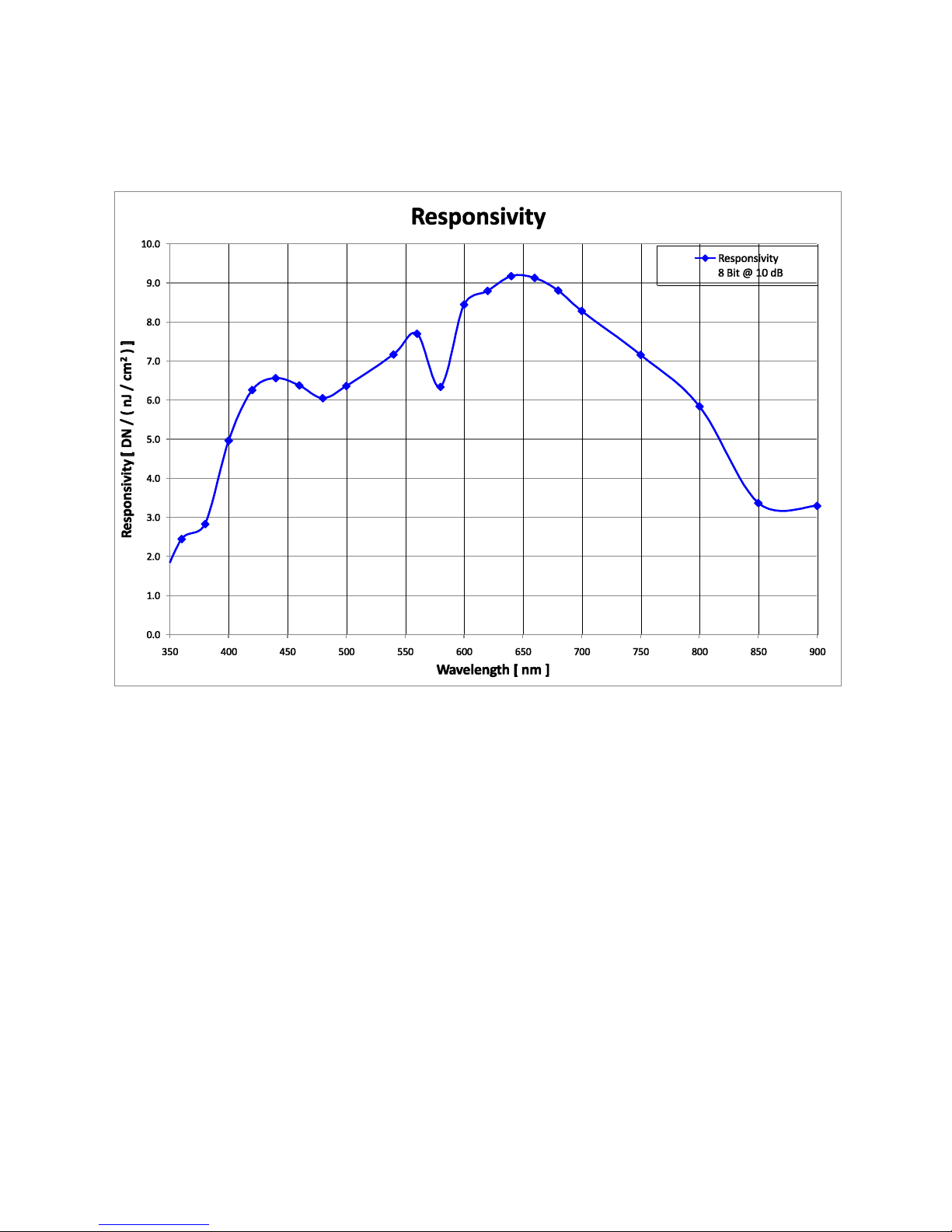
1.3 Responsivity
Responsivity vs. Wavelength: Measured from the camera.
03-032-20099-02 Teledyne DALSA

Piranha3 16K HSLink and Camera Link User Manual
9
2
Camera Hardware Interface
2.1 Installation Overview
(This installation overview assumes you have not installed any system components yet.)
When installing your camera, you should take these steps:
1. Power down all equipment.
2. Follow th e m anu factu rer’s instruction s to install the framegrabber (if applicable). Be sure to observe all
static precautions.
3. Install any necessary imaging software.
4. Before connecting power to the camera, test all power supplies. Ensure that all the correct voltages are
present at the camera end of the power cable. Power supplies must meet the requirements defined in the
Power Connector section below .
5. Inspect all cables and connectors prior to installation. Do not use damaged cables or connectors or the
camera m ay be damaged.
6. Connect data and power cables.
7. After connecting cables, apply power to the camera.
8. Use the verify voltage (vv) command to verify that the camera is receiving a voltage of 12 to 15 DC. If the
camera is receiving less than the recommended voltage, then you may have to upgrade and/ or shorten
the power cable you are using.
8. Check the diagnostic LED. See LED Status Indicator for an LED description.
You must also set up the other components of your system, including light sources, camera mounts*, host
computers, optics, encoders, and so on.
*Please see 4.2 High Temperature and Mounting for more information on camera mounting and heat
dispertion.
Teledyne DALSA 03-032-20099-02
Piranha3 16K HSLink and Camera Link User Manual
10
!
Color of Status LED
Meaning
Green solid
Camera is operational and functioning correctly.
Green blinking, fast
FG only - LVAL present but not grabbing (20 second time out)
Green blinking, slow
Waiting for LVAL/ Trigger
Line Scan – 5 second timeout
Orange (red and green on together) solid
Running on FPGA/ micro backup
B
HSLink
SFF_8470 or Cx4
with thumbscrews
+ 12 V to + 15 V DC
Hirose 6-pin HR10A-7P-6S
A
B
A
Camera Link (Full Configuration)
High-density 26-pin MDR26 connector
Diagnostic LED
C
D
A
C
D
D
C
Power
Control & Data
Status
P3-80-16K40-00-R Camera Link P3-S0-16Kx0-00-R HSLink
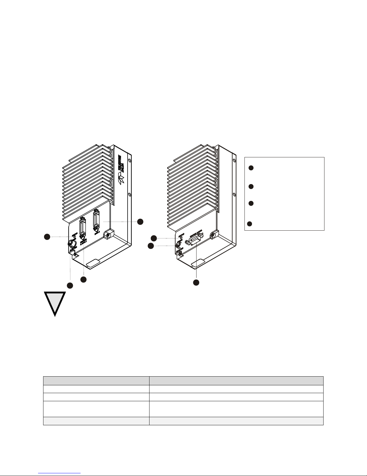
2.2 Input/Output Connectors and LED
The camera uses:
A diagnostic LED for monitoring the camera. See LED Status Indicator in section LED Status Indicator for
details.
A 6-pin Hirose connector for power. Refer to the Power Connector section below for details.
The HSLink modles use a SFF_8470 / CX4 (with thumbscrews) for control, data and serial
communication.
The Camera Link model uses 2 high-density 26-pin MDR26 connectors for control, data and serial
communication.
Figure 1: Input and Output Connectors
WARNING: It is extremely important that you supply the appropriate voltages to your camera. Incorrect
voltages will damage the camera.
LED Status Indicator
The camera is equipped with an LED used to display the operational status of the camera. The table below
summarizes the operating states of the camera and the corresponding LED states.
When more than one condition is active, the LED indicates the condition with the highest prio rity. Error and
warning states are accompanied by corresponding messages further describing the current camera status.
Table 3: HSLink Diagnostic LED
03-032-20099-02 Teledyne DALSA
Piranha3 16K HSLink and Camera Link User Manual
11
!
Color of Status LED
Meaning
Orange blinking, slow
Loss of functionality
Orange one pulse of 0.2 sec
Random Error with HSLINK
Red blinking, fast
Fatal Error- Loss of FPGA code and or micro code
Red blinking, medium
Fatal Error- Loss of other hardware which prevents operation
Red blinking, slow
Over temperature (HSLINK CMD channel still functional)
Red / Green alternating, fast
Link Up, but idle not locked (held in Farend reset)
Red / Green alternating, medium
Incompatilbe HSLINK configuration
Red / Green alternating, slow
Looking for Link
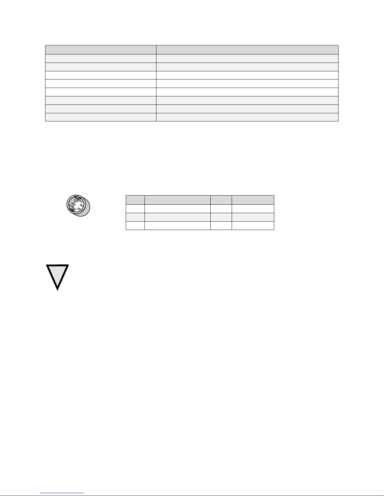
Hirose 6-pin Circular Male
5
4
6
2
3
1
Mating Part: HIROSE
HR10A-7P-6S
Table 4: Hirose Pin Description
Pin
Description
Pin
Description
1
Min +12 to Max +15V
4
GND
2
Min +12 to Max +15V
5
GND
3
Min +12 to Max +15V
6
GND
Power Connectors
2.2.2 Power Connector
Figure 2: Hirose 6-pin Circular Male—Power Connector
The camera requires a single voltage input (+12 V to +15 V DC). The camera meets all performance
specifications using standard switching power supplies, although well-regulated linear supplies provide
optimum performance.
WARNING: When setting up the camera’s power supplies follow these guidelines:
Apply the appropriate, reliable voltages
Protect the camera with a slow-blow fuse between power supply and camera (2x nominal current).
Do not use the shield on a multi-conductor cable for grou nd.
Keep leads as short as possible to reduce voltage drop.
Use high-quality linear supplies to minimize noise.
Use an isolated type power supply to prevent LVDS common mode range violation.
A stable supply of power must be maintained during code upgrades. Camera will fail if power is lost or
unstable while updating code. The user can not recover from this failure and the camera will have to be
returned to Teledyne DALSA for repair.
Note: Camera performance specifications are not guaranteed if your power supply does not meet these requirements.
Teledyne DALSA 03-032-20099-02

Piranha3 16K HSLink and Camera Link User Manual
12
SFF_8470 (or CX4) with thumbscrews
Signal
Camera
Frame Grabber Input
Frame Grabber Signal
DataTx 2+
S16
S1
DataRx 2+
DataTx 2-
S15
S2
DataRx 2-
DataTx 1+
S14
S3
DataRx 1+
DataTx 1-
S13
S4
DataRx 1-
DataTx 0+
S12
S5
DataRx 0+
DataTx 0-
S11
S6
DataRx 0-
Cmd_T+
S10
S7
Cmd R+
Cmd_T-
S9
S8
Cmd R-
Cmd_R-
S8
S9
Cmd_T-
Cmd_R+
S7
S10
Cmd_T+
DataTx 5-
S6
S11
DataRx 5-
DataTx 5+
S5
S12
DataRx 5+
DataTx 4-
S4
S13
DataRx 4-
DataTx 4+
S3
S14
DataRx 4+
DataTx 3-
S2
S15
DataRx 3-
DataTx 3+
S1
S16
DataRx 3+
Signal
Ground
G1- G9
G1- G9
Signal Ground
Signal
Ground
H1-H2
H1-H2
Signal Ground
Signal
Configuration
CC1
EXSYNC
Data Connectors
HSLink Pinout
Input Signals
The camera accepts control inputs through the H SLink connector.
Table 5: Camera Control Configuration
The camera ships in internal sync, internal programmed integration.
EXSYNC (Triggers Frame Readout)
Frame rate can be set internally using the serial interface. The external control signal EXSYNC is optional and
enabled through the serial interface. This camera uses the falling edge of EXSYNC to trigger pixel readout. See
section Exposure Mode and Line Rate for details on how to set frame times, exposure times, and camera
modes.
An Important Note: Do not stop imaging with the ESYNC signal high. If the EXSYNC signal is high when
imaging stops an imaging artifact will remain on the next line.
03-032-20099-02 Teledyne DALSA
Piranha3 16K HSLink and Camera Link User Manual
13
Rx Tx 5 serial lanes (8 or 10 bit)
6 serial lanes (12 bit)
@ 312.5 Mb/sec
Camera
Frame Grabber
Output Signals
Note that LVAL and FVAL are embedded in data lanes. For additional information refer to the HSLink
supplementary information below .
Frame Grabbers
The cameras (HSLink) are compatible with the Xcelera-HS PX8 framegrabber.
Teledyne DALSA 03-032-20099-02

Piranha3 16K HSLink and Camera Link User Manual
14
HSLINK Function
Production
Comment
Cable Disconnect
Recovery
Yes
Cameras will only properly lock to frame grabber
when the camera is turned on before or after
starting the d ata acquisition program. Turn off the
camera when exiting a program that uses the
Frame grabber.
Data Forw arding
Yes
Customer must identify the Master/ Slave Frame
grabber during the system configuration step.
There is no Master/ Slave communication channel
support.
Communication
Between FG
No
This is the GMII command channel and will enable
auto enumeration of slaves and data resend
requests from the slaves.
Video Data Resend
No
Master/ Slave command channel used for error
communication from slave is not available at this
time. Can be field upgraded.
LED functions
Yes
GeniCam
No
Use the ASCII serial command set.
Trigger Control
Yes
12 bit mode
Yes
Data will be packed on the Link. This will exceed
the PCIx 8 Gen 1 bandwidth.
Missed Trigger Flag
Yes
DATA CRC Error
Flag
Yes
CRC error counters available
Header Error Flag
Yes
Header error counter available
8b/ 10B Error counter
Yes
Enables BER calculation
Test Patterns
Yes
Good for system debug
Data Lost Flag
No
Indicates missing rows of information
Camera Data buffer
overflow
No
Idle Lock Lost
No
Far end Reset
No
Cmd Packet Failure
No
Master/ Slave
HSLINK reset
No
HSLINK and Frame Grabber Supplementary Information
Teledyne DALSA designed and pioneered the HSLink as a comprehensive camera-frame grabber
communication standard targeted at machine vision industry use. The HSLink 12k and frame grabber product
are based on the fundamental capabilities of this new interface.
We are working with industry partners to im prove an d to broaden th e interface’s ap peal for th e m achin e vision
industry and as a result expect that the original specification will change and be improved. Products delivered
during this draft specification phase will be field upgradeable so that customers can gain the benefit from an
industry approved interface. The table below summarizes the major functions supported.
03-032-20099-02 Teledyne DALSA

Piranha3 16K HSLink and Camera Link User Manual
15
Camera
Master
Id 0
Slave 1
ID 1
Slave 2
ID 0
Slave 3
ID 1
**3M part 14X26-SZLB-XXX-0LC is a complete
cable assembly, including connectors.
Unused pairs should be terminated in 100 ohms
at both ends of the cable.
Camera to Master Frame grabber Power On Discovery Notes
The camera and frame grabber will correctly discover each other if either the camera or the frame grabber are
turned on or off, regardless of order.
Master to Slave Power On Discovery Notes
Please Note: The communication channel between master and slave frame grabbers is not functional at this
time and therefore must be configured manually, as shown below:
The power on sequence for the cameras to guarantee functionality is:
1. Camera/ Master
2. Slave 1
3. Slave 2
4. Slave 3
5. Slave 4
6. Slave 5
The slave should only be turned on once an image is acquired by the preceding slave.
2.2.3 Camera Link Data Connector
Camera Link information available from our Web site
The Camera Link Implementation Road Map, available from the Teledyne DALSA Web site,
http:/ www.teledynedalsa.com/ mv/ knowledge/ appnotes.aspx, contains detailed information on
implementing Camera Link, including configuration and signal information.
Figure 3: Camera Link MDR26 Connector
A note concerning the length of the Camera Link cables
The length of the cables over which data can be transmitted without loss depends on the data rate and on the
quality of the cables.
The camera is tested using a recognized brand of cable with a length of 5 meters. Data tran smission is not
guaranteed if you are using a cable greater than 5 meters in length.
Teledyne DALSA 03-032-20099-02

Piranha3 16K HSLink and Camera Link User Manual
16
Configuration
8 Bit Ports
Supported
Serializer
Bit Width
Number
of Chips
Number of MDR26 Connectors
Full
A, B, C, D, E, F, G, H
28 3 2
Full Configuration
Camera Connector
Right Angle
Frame Grabber
Channel Link
Signal
Cable Name
1 1 inner shield
Inner Shield
14
14
inner shield
Inner Shield
2
25
Y0-
PAIR1-
15
12
Y0+
PAIR1+
3
24
Y1-
PAIR2-
16
11
Y1+
PAIR2+
4
23
Y2-
PAIR3-
17
10
Y2+
PAIR3+
5
22
Yclk-
PAIR4-
18 9 Yclk+
PAIR4+
6
21
Y3-
PAIR5-
19 8 Y3+
PAIR5+
7
20
100 ohm
PAIR6+
20 7 terminated
PAIR6-
8
19
Z0-
PAIR7-
21 6 Z0+
PAIR7+
9
18
Z1-
PAIR8-
22 5 Z1+
PAIR8+
10
17
Z2-
PAIR9+
23 4 Z2+
PAIR9-
11
16
Zclk-
PAIR10-
24 3 Zclk+
PAIR10+
12
15
Z3-
PAIR11+
25 2 Z3+
PAIR11-
13
13
inner shield
Inner Shield
26
26
inner shield
Inner Shield
Signal
Configuration
CC1
EXSYNC
CC2
PRIN
CC3
Spare
CC4
Spare
Camera Link Configuration
The Camera Link interface is implemented as a Medium or Full Configuration in the Piranha 3 cameras.
Table 6: Camera Link Hardware Configuration Summary
Table 7: Camera Link Connector Pinout
Table 8: Camera Control Configuration
03-032-20099-02 Teledyne DALSA

Piranha3 16K HSLink and Camera Link User Manual
17
Camera Link Mode Configuration (Controlled by clm command): Full and Bit Depth 8
Command
Camera Link Taps
Pixel Rate Configuration (Controlled by sot command)
sdw 8
8 Camera Link taps where:
1 = Every 4th Odd Pixel
2 = Every 4th Even Pixel
3 = Every 4th Odd Pixel
4 = Every 4th Even Pixel
1 = Every 4th Odd Pixel
2 = Every 4th Even Pixel
3 = Every 4th Odd Pixel
4 = Every 4th Even Pixel
sot 320 = NA
Camera Link Mode Configuration (Controlled by clm command): Full and Bit Depth 10
Command
Camera Link Taps
Pixel Rate Configuration (Controlled by sot command)
sdw 10
8 Camera Link taps where:
1 = Every 4th Odd Pixel
2 = Every 4th Even Pixel
3 = Every 4th Odd Pixel
4 = Every 4th Even Pixel
1 = Every 4th Odd Pixel
2 = Every 4th Even Pixel
3 = Every 4th Odd Pixel
4 = Every 4th Even Pixel
sot 320 = NA
Clocking Signal
Indicates
LVAL (high)
Outputting valid line
DVAL (high)
Valid data
STROBE (rising edge)
Valid data
FVAL (high)
Outputting valid frame
IMPORTANT:
This camera’s data
should be sampled on
the rising edge of
STROBE.
i
Table 9: Camera Link Pixel Readout Configurations: Full Camera Link Configuration and Bit Depth 8
Table 10: Camera Link Pixel Readout Configurations: Full Camera Link Configuration and Bit Depth 10
Input Signals, Camera Link
The camera accepts control inputs through the Camera Link MDR26F connector s.
The camera ships in internal sync, internal programmed integration (exposure mode 2).
EXSYNC (Triggers Line Readout)
Line rate can be set internally using the serial interface. The external control signal EXSYNC is optional and
enabled through the serial interface. This camera uses the falling edge of EXSYNC to trigger line readout.
Section 3.2 Exposure Mode and Line Rate details how to set frame times, exposure times, and camera modes.
Output Signals, Camera Link
These signals indicate when data is valid, allowing you to clock the data from the camera
to your acquisition system. These signals are part of the Camera Link configuration and
you should refer to the Camera Link Implementation Road Map, available here, for the
standard location of these signals.
Teledyne DALSA 03-032-20099-02

Piranha3 16K HSLink and Camera Link User Manual
18
Symbol
Definition
Min (ns)
twSYNC
The minimum low width of the EXSYNC pulse when not in SMART
EXSYNC mode.
100
twSYNC
(SMART)
*
The minimum low width of the EXSYNC pulse when in SMART EXSYNC
modes to guarantee the photosites are reset.
3,000
twSYNC_INT
The m inim u m wid th of th e hig h p ulse w h en th e ― SMART EXSYN C‖ featu re
is turned off
100
twSYNC_INT
(SMART)
*
Is the in tegration tim e w h en th e ―SMART EXSYN C‖ featu r e is available an d
turned on. Note that the minimum time is necessary to guarantee proper
operation.
3,000
The camera internally digitizes 12 bits and outputs 8 MSB or a ll 12 bits d ep en d ing on the cam era’s
Camera Link operating mod e.
2.3 Camera Link Video Timing
Figure 4: Piranha 3 Overview Timing Showing Input and Output Relationships
Figure 5: Piranha 3 Fixed (Programmed) Integration Timing with External EXSYNC
Table 11: Piranha 3 Input and Output
03-032-20099-02 Teledyne DALSA

Piranha3 16K HSLink and Camera Link User Manual
19
Symbol
Definition
Min (ns)
tLINE PERIOD
(t LP)
The minimum and maximum line times made up of tTransfer, tREADOUT
plus tOVERHEAD to meet specifications.
53,190 (12k)
106,382 (8k)
tTransfer
The time from the reception of the falling edge of EXSYNC to the rising edge
of LVAL when pretrigger is set to zero. Pretrigger reduces the number of
clocks to the rising edge of LVAL but doesn ’t ch ange the tim e to th e first
valid pixel. If the fixed integration time mode of operation is available and
selected then the integration time is ad ded to the specified value.
3,725 ±25
twFixed Int.
Fixed Integration Time mode of operation for variable exsync frequency.
800
tREADOUT
Is the number of pixels per tap times the readout clock period. Pretrigger = 0.
38,400 (12k)
25,600 (8k)
tOVERHEAD
Is the number of pixels that must elapse after the falling edge of LVAL
before the EXSYNC signal can be asserted. This time is used to clamp the
internal analog electronics
425±25
thPR
Applies when the PRIN exposure control feature is enabled . The PRIN
signal must be held a minimum time after the EXSYNC falling edge to avoid
losing the integrated charge
Don’t car e
twPR_LOW
Minimum Low time to assure complete photosite reset
3,000
tPR_SET
The nominal time that the photo sites are integrating. Clock synchronization
will lead to integration time jitter, which is shown in the specification as +/ values. The user should command times greater than these to ensure proper
charge transfer from the photosites. Failure to meet this requirement may
result in blooming in the Horizontal Shift Register.
3,000
Teledyne DALSA 03-032-20099-02

Piranha3 16K HSLink and Camera Link User Manual
20
i
This chapter outlines the
more commonly used
commands. See section A2
Commands for a list of all
available commands.
3
Software Interface: How to
Control the Camera
All camera features can be controlled through the serial interface. The camera can also be used without the
serial interface after it has been set up correctly. Functions available include:
Controlling basic camera functions such as gain and sync signal source
Flat field correction
Generating a test pattern for debugging
The serial interface uses a simple ASCII-based protocol and the PC does not require any custom software.
Note: The command set may have changed from previous camera models. Do not assume that commands
perform similarly to older cameras.
Serial Protocol Defaults
8 data bits
1 stop bit
No parity
No flow control
115,200 kbps baud rate
Camera does not echo characters
Command Format
When entering commands, remember that:
A carriage return <CR> ends each command.
A space or multiple space characters separate parameters. Tabs or commas are invalid parameter
separators.
Upper and lowercase characters are accepted
The backspace key is supported
The camera will answer each command with either <CR><LF> OK > or <CR><LF> Error xx: Error
Message > or Warning xx: Warning Message >. The > is used exclusively as the last character sent by the
camera.
03-032-20099-02 Teledyne DALSA

Piranha3 16K HSLink and Camera Link User Manual
21
Syntax:
h
Syntax:
gh
Notes:
For m ore in formation on the camer a’s ―get‖ co m m an d s, refer to
section Returning Camera Settings.
The following parameter conventions are used in the manual:
• i = integer value
• f = real number
• m = member of a set
• s = string
• t = tap id
• x = pixel column number
• y = pixel row number
Example: to return the current camera settings
gcp <CR>
Setting Baud Rate
Note on the camera and baud rate
The cameras employ a 115,200 fixed signal baud rate.
Camera Help Screen
For quick help, the camera can return all available commands and parameters through the serial interface.
There are two different help screens available. One lists all of the available commands to configure camera
operation. The other help screen lists all of the commands available for retrieving camera parameters (these are
called ― get‖ com mand s).
To view the help screen listing all of the camera configuration commands, use the command:
To view a help screen listing all of the “get” commands, use the command:
The camera configuration command help screen lists all commands available. Parameter ranges displayed are
the extreme ranges available. Depending on the current camera operating conditions, you may not be able to
obtain these values. If this occurs, values are clipped and the camera returns a warning message.
Some commands may not be available in your current operating mode. The help screen displays NA in this
case.
3.1 First Power Up Camera Settings
When the camera is powered up for the first time, it operates using the following factory settings:
Exposure mode 2
10 kHz line rate
Factory gain + 10 dB
Factory calibrated FPN and PRNU coefficients.
Note regarding start-up times: This camera requires approximately 20 seconds to power up.
Teledyne DALSA 03-032-20099-02

Piranha3 16K HSLink and Camera Link User Manual
22
1. You must first set the camera’s exposure mode using the sem command.
2. Next, if using mode 2, use the command ssf to set the line rate. Refer to section Setting
Frame Rate for details.
Purpose:
Sets th e cam era’s exposu re m od e allow ing you t o control your
sync and line rate generation.
Syntax:
sem m
Syntax Elements:
m
Exposure mode to use 2 / 3/ 4 / 6*. Factory setting is 2.
Notes:
Refer to Table 12: Exposure Modes for a quick list of available
modes or to the follow ing sections for a more detailed
explanation including timing diagrams.
To obtain the current value of the exposure mode, use the
command gcp or get sem.
When setting the camera to external signal modes, EXSYNC
must be supplied.
Related Commands:
ssf
Example:
sem 3
Mode
SYNC
Description
2
Internal
Yes
Yes
3
Internal
No
Yes
Maximum exposure time.
4
External
No
No
Exposure time equals EXSYNC high time.
3.2 Exposure Mode and Line Rate
How to Set Exposure Mode and Line Rate
You have a choice of operating the camera in one of four exposure modes. Depending on your mode of
operation, the cam era ’s lin e rate (synchronization) can be generated internally through the software command
ssf or set externally with an EXSYNC signal (CC1).
To select how you want the camera’s line rate to be generated:
Setting the Exposure Mode
Table 12: Exposure Modes
Programmable Line Rate Programmable Exposure Time
03-032-20099-02 Teledyne DALSA

Piranha3 16K HSLink and Camera Link User Manual
23
Mode
SYNC
Description
*6
External
No
Yes
In this mode the line rate and the exposure time are mutually
restrained by this formular:
Maximum user line rate = 1 / ( ( 1 / Max camera line rate) +
exposure time )
Assume the camera max line rate is 40 KHz in the following
examples.
Ex. 1) If the user wants the line rate is 25KHz, the max exposure
time should be equal or smaller than 1/ 25KHz - 1/ 40KHz = 15
us;
Ex. 2) If the user sets the exposure time to 25 us, the line rate
should be equal or lower than 1/ (1/ 40KHz + 25us) = 20KHz.
Mode 2: Internal SYNC, Programmable Line Rate and Exposure Time
INTERNAL SYNC
EXPOSURE
Mode 3: Internal SYNC, Maximum Exposure Time
INTERNAL SYNC
EXPOSURE
1 µs
Mode 4: External SYNC
EXTERNAL SYNC
EXPOSURE
Mode 6: External SYNC, Programmable Exposure Time
EXTERNAL SYNC
EXPOSURE
Exposure Modes in Detail
Figure 6: Timing Diagrams
Teledyne DALSA 03-032-20099-02

Piranha3 16K HSLink and Camera Link User Manual
24
Purpose:
Sets th e cam era’s fram e rate in Hz. Camer a m u st be op era ting in exp osure m od e 2.
Syntax:
ssf f
Syntax Elements:
f
Set the frame rate to a value from: 1 to 72070 (P3-S0-16k40 HSLink) or 1 to 40000 (P3S0-16K20 HSLink and P3-80-16K40 Camera Link.
Value rounded up/ down as required.
Notes:
If you enter an invalid frame rate frequency the value, the camera clips the frame rate
to be within the current operating range and a warning message is returned .
If you enter a frame rate frequency out of the range displayed on the help screen, an
error message is returned and the frame rate remains unchanged.
To retu rn th e ca m era’s fram e rate, u se the com m ad gcp or get ssf.
Related Commands:
sem
Example:
ssf 10000
Purpose:
Sets the exposure time in µs. The camera must be operating in mode 2, 3 or 8 to use this
feature.
Syntax:
set f
Syntax Elements:
f
The exposure time value in a range from: 1 to 8888 µs.
Notes:
To read the current exposure time, use the gcp command .
If you enter an invalid exposure time, an error message is returned.
Related Commands:
sem, ssf
Example:
set 400.5
Setting Frame Rate and Exposure Time
Setting the Frame Rate
Setting the Exposure Time
3.3 Data Processing
Digital Signal Processing Chain
Processing Chain Overview and Description
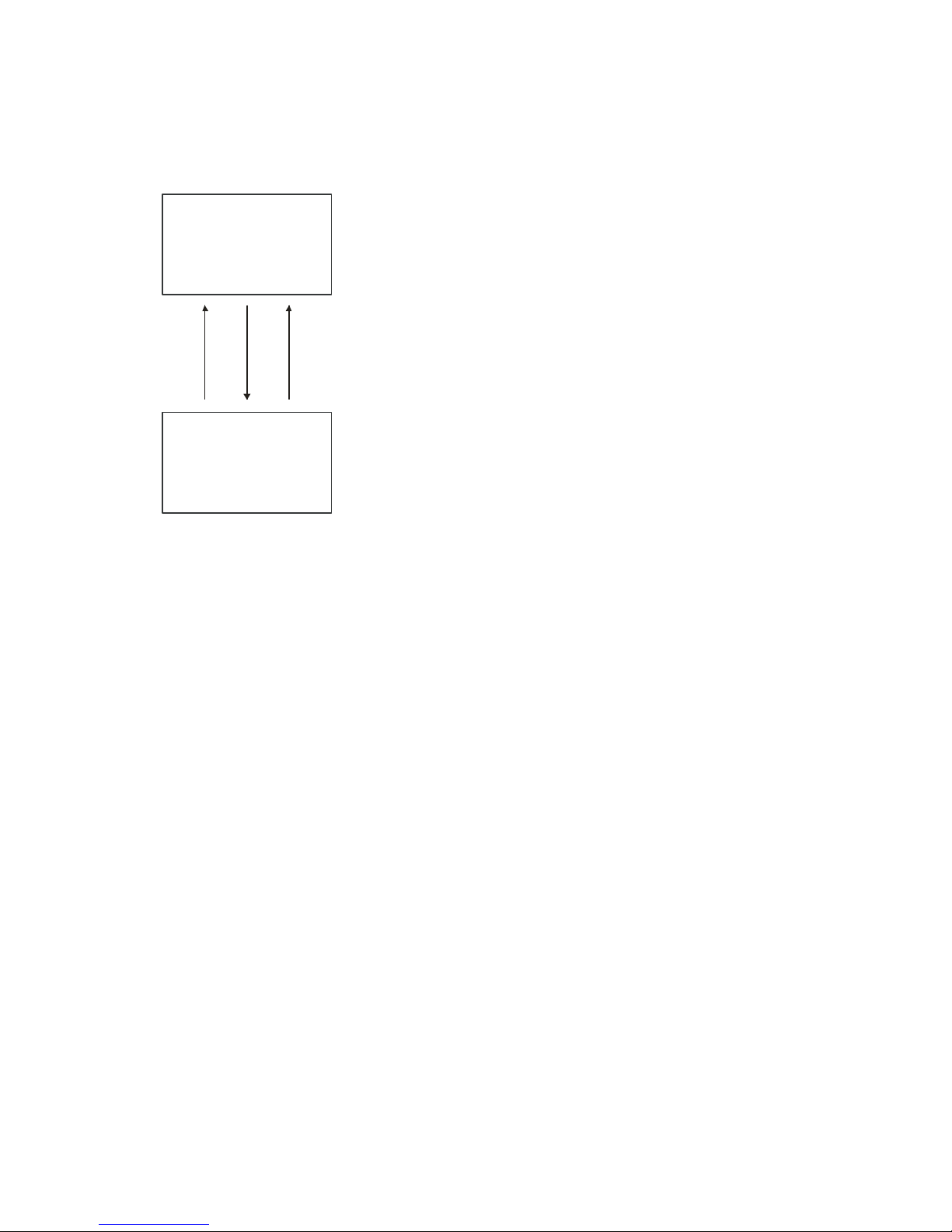
The follow ing d iagram sh ow s a sim p lified block d iag ram of th e camer a’s d igital processing chain.
The digital processing chain contains the digital gain, FPN correction (factory set), the PRNU correction, the
background subtract, and the system gain and offset. All of these elements are user programm able.
Notes:
FPN and PRNU coefficients are stored separately. To save the current PRNU coefficients, use the
command wpc.
03-032-20099-02 Teledyne DALSA

Piranha3 16K HSLink and Camera Link User Manual
25
Digital Processing
PRNU
coefficients
background
subtract
digital video
cpa
ssb
sab
background
addition
FPN
coefficients
(factory set)
digital
gain
sg
system
gain
ssg
Figure 7: Signal Processing Chain
Digital Processing
1. Fixed pattern noise (FPN) calibration (calculated at the factory) is used to subtract away individual pixel
dark current.
2. Photo-Response Non-Uniformity (PRNU) coefficients are used to correct the difference in responsivity of
individual pixels (i.e. given the same amount of light different pixels will charge up at different rates) and
the change in light intensity across the image either because of the light source or due to optical
aberrations (e.g. there many be more light in the center of the image). PRNU coefficients are multipliers
and are defined to be of a value greater than or equal to 1. This ensures that all pixels will saturate
together. When using PRNU correction, it is important that the A/ D offset and Fixed Pattern Noise (FPN)
or per pixel offsets are subtracted prior to the multiplication by the PRNU coefficient. The subtraction of
these 2 components ensure that the video supplied to the PRNU multiplier is nominally zero a nd zero
multiplied by anything is still zero resulting in no PRNU coefficient induced FPN. If the offset is not
subtracted from the video then there will be artifacts in the video at low light caused by the multiplication
of the offset value by the PRNU coefficients.
3. Background subtract (ssb command), system gain (ssg command), and background addition (sab) are
used to increase image contrast after FPN and PRNU calibration. It is useful for systems that process 8-bit
data but want to take advantage of the camer a’s 12-bit digital processing chain. For example, if you find
that your image is consistently between 128 and 255 DN (8-bit), you can subtract off 128 (ssb 2048) and
then multiply by 2 (ssg 8192) to get an output range from 0 to 255.
Setting Gain
Use the set gain (sg) command to set the gain on taps 0 to 32 and in a range of ± 24 dB.
Command and parameter: sg tf, where t is tap 0 to 32 and f is ± 24 dB.
Calibrating the Camera to Remove Non-Uniformity (Flat Field
Correction)
Flat Field Correction Overview
This camera has the ability to calculate correction coefficients in order to remove non -uniformity in the image.
This video correction operates on a pixel-by-pixel basis and implements a two point correction for each pixel.
This correction can reduce or eliminate image distortion caused by the following factors:
Teledyne DALSA 03-032-20099-02
Fixed Pattern Noise (FPN)
Photo Response Non Uniformity (PRNU)

Piranha3 16K HSLink and Camera Link User Manual
26
where
V
output
=
digital output pixel value
V
input
=
digital input pixel value from the CCD
PRNU( pixel)
=
PRNU correction coefficient for this pixel
FPN( pixel )
=
FPN correction coefficient for this pixel
Note: If your
illumination or white
reference does not
extend the full field of
view of the camera,
the camera will send a
warning.
Lens and light source non -uniformity Correction is implemented such that for each pixel:
V
output
=[(V
- dark offset- FPN ( pixel )) * digital gain * PRNU (pixel)]
input
The algorithm is performed in two steps. The fixed offset (FPN) is determined first by performing a calculation
without any light. This calibration determines exactly how much offset to subtract per pixel in order to obtain
flat output when the CCD is not exposed.
The white light calibration is performed next to determine the multiplication factors required to bring each
pixel to the required value (target) for flat, white output. Video output is set slightly above the brightest pixel
(depending on offset subtracted).
Flat Field Correction Restrictions
The FPN correction is done in the factory. Results of the FPN correction are used in the PRNU procedure. We
recommend that you repeat the correction when a temperature change greater than 10°C occurs or if you
change the integration time.
PRNU correction requires a clean, white reference. The quality of this reference is important for proper
calibration. White paper is often not sufficient because the grain in the white paper will distort the correction.
White plastic or white ceramic will lead to better balancing.
For best results, ensure that:
1. 60 Hz ambient light flicker is sufficiently low not to affect camera performance and
calibration results.
2. The brightest pixel should be slightly below the target output.
3. When 6.25% (or more) of pixels from a single row within the region of interest are
clipped, flat field correction results may be inaccurate.
Calibration Overview
When a camera images a uniformly lit field , ideally, all of the pixels will have the same gray value. However,
in practice, this is rarely the case (see example below) as a number of factors can contribute to gray scale nonuniformity in an image: Lighting non-uniformities and lens distortion, PRNU (pixel response non-uniformity)
in the imager, FPN (fixed pattern noise) in the imager, etc.
Figure 8. Image with non-uniformities
By calibrating the camera you can eliminate the small gain difference between pixels and compensate for light
distortion. This calibration employs a two-point correction that is applied to the raw value of each pixel so that
non-uniformities are flattened out. The response of each pixel will appear to be virtually identical to that of all
the other pixels of the sensor for an equal amount of exposure.
03-032-20099-02 Teledyne DALSA

Piranha3 16K HSLink and Camera Link User Manual
27
Calibration Steps
Step 1: Preparing for Calibration
If you do not want to change the current camera settings, but want to calibrate the camera, skip this step and
move to Step 2: PRNU Calibration.
To check the current camera settings, use the get camera parameters (gcp) or the get commands. You can
change some or all of the following settings before calibrating:
Set exposure mode using the command sem m, where m = 2/ 3/ 4/ / 6
For example, sem 2
Set line sync frequency (line rate) using the command ssf f, where f = - 72 kHz
For example, ssf 5000
Set exposure time using the command set f, where f = 1 - 8888 µs in an available mode.
For example, set 100
Set gain using comm and sg t i, where t are the taps 0 to 21 and i = ± 24 db
For example, sg t 0
Save user settings using command wus.
A Note on FPN or Dark Calibration
FPN calibration (also called dark calibration) is done in the factory.
Step 2: PRNU or White Calibration
1. Remove the lens cap and prepare a white, uniform target.
2. Adjust the line rate so that the average output is about 80% of the full output, or below the PRNU target
value by:
Adjusting the lighting, if you are using an internal exposu re mode. Or,
Adjusting the line rate, if you are using the Smart Exsync mode.
3. Calibrate the PRNU using the command cpa 2 i, where 2 is the PRNU calculated using the entered target
value as shown in the formula on page 28 and i is the target value and the value of i is 1024 to 4055 DN.
For example: cpa 2 3300
4. Save the PRNU coefficients using the command wpc.
For example: wpc
Note: Both the FPN and PRNU coefficients are always turned on.
Teledyne DALSA 03-032-20099-02

Piranha3 16K HSLink and Camera Link User Manual
28
Purpose:
Sets the current gain setting to be the 0 dB point. This is useful after tap gain matching to
allow you to change the gain on all taps by the same amount.
Syntax:
ugr
Purpose:
Performs PRNU calibration to user entered value and eliminates the difference in
responsivity between the most and least sensitive pixel creating a uniform response to light.
Using this command, you must provide a calibration target.
Executing these algorithms causes the ssb command to be set to 0 (no background
subtraction), the ssg command to 0 (unity digital gain), and the sab command to 0 (no
background addition). The pixel coefficients are disabled during the algorithm execution but
returned to the state they were prior to command execution.
Syntax:
cpa m i
Syntax Elements:
m
PRNU calibration algorithm to use:
2 = Calculates the PRNU coefficients using the entered target value as show n below:
PRNU Coefficient =
Target
(AVG Pixel Value ) - FPN
i i
i
The calculation is performed for all sensor pixels but warnings are only applied to pixels
in the region of interest. This algorithm is useful for achieving uniform output across
multiple cameras. Is is important that the target value (set with the next parameter) is set
to be at least equal to the highest pixel across all cameras so that all pixels can reach the
highest pixel value during calibration.
4 = Calculates the PRN U coefficient in the same way as cpa 2 with the exception that this
command only calculates PRNU for pixels within the current Region of Interest (ROI).
i
Peak target value in a range from 1024 to 4055 DN. The target value must be greater than
the current peak output value.
Notes:
The values for background subtract (ssb), system gain (ssg) and background add (sab)
are set to 0, 1, and 0 respectively after using the cpa command.
Example:
cpa 2 4000
Purpose:
Sets an in d ivid u a l p ixel’s PRNU coefficien t.
Syntax:
spc x i
Syntax Elements:
x
Digital Signal Processing for Processing
Updating the Gain Reference
To update the gain reference:
FPN Correction
Note: FPN correction is done in the factory.
PRNU Correction
Performing PRNU to a user entered value
Setting a Pixel’s PRNU Coefficient
03-032-20099-02 Teledyne DALSA

Piranha3 16K HSLink and Camera Link User Manual
29
The pixel number from 1 to 16384.
i
Coefficient value in a range from 0 to 65535 where:
Purpose:
Returns the current PRNU pixel coefficients for the range specified by x1 and x2.
Syntax:
dpc x1 x2
Syntax Elements:
x1
Start pixel to display in a range from 1 to 16384.
x2
End pixel to display in a range from 1 to 16384.
Notes:
If x2<x1 then x2 is forced to be x1.
Example:
dpc 10 20
Purpse:
Use the background subtract command after performing flat field correction if you want
to improve your image in a low contrast scene. You should try to make your darkest pixel
in the scene equal to zero.
Sytax
ssb i
Syntax Elements:
i
Subtracted value in a range in DN from 0 to 1024 (12 bit LSB).
Notes:
See the following section for details on the ssg command.
Related Commands
ssg
Example
ssb 500
Purpose:
Improves signal output swing after a background subtract. When subtracting a digital
value from the digital video signal, using the ssb command, the output can no longer
reach its maximum. Use this command to correct for this where:
ssg value =
max output value
max output value - ssb value
Syntax:
ssg i
Syntax Elements:
i
Gain setting. The gain ranges are 0 to 61438. The d igital video values are
multiplied by this value where:
System Gain=
i
4096
1 +
Notes:
Use this command in conjunction w ith the ssb command (described above).
prnu coefficient =
i
4096
1 +
Returning PRNU Coefficients
Subtracting Background
Setting System Gain
Teledyne DALSA 03-032-20099-02

Piranha3 16K HSLink and Camera Link User Manual
30
We recommend that i is never set below 4096. Setting i to 0 will result in only 0
output data.
Digital offset is set to zero after sending the command
Related Commands:
ssb, sab
Example:
ssg 4500
Purpse:
Use the background ad d command after performing flat field correction if you want to
improve your image in a high contrast scene. Use this command to increase the true black
above 0 DN.
Sytax
sab i
Syntax Elements:
i
Add value in a range in DN from 0 to 4096 (12 bit LSB).
Notes:
See the following section for details on the ssg command.
Related Commands
ssg, ssb
Example
sab 500
Factory
Settings
Current
Session
wus wpc,wfc,
rus lpc,
rfs
User
Settings
Adding Background
3.4 Saving and Restoring Settings
Saving and Restoring Factory and User Settings
Figure 9: Saving and Restoring Overview
Factory Settings
You can restore the original factory settings, including the factory calibrated pixel coefficient set, at any time
using the command rfs.
User Settings
You can save or restore your user settings to non -volatile memory using the following commands.
To save all current user settings to EEPROM for the current mode use the command wus. The camera will
automatically restore the saved user settings when powered up.
WARNING: While settings are being written to nonvolatile memory, do not power down camera or camera memory
may be corrupted.
03-032-20099-02 Teledyne DALSA

Piranha3 16K HSLink and Camera Link User Manual
31
Purpose:
When saving and loading camera settings (e.g. PRNU coefficients), you have a choice of
saving up to five different sets and loading from six different sets (five user and one
factory). This command determines the set number from where these values are loaded
and saved.
Syntax:
ssn
Syntax Elements:
i
0 = Factory set. Settings can only be loaded from this set.
1 - 5 = User sets. You can save, or load settings with these sets.
Note:
The camera powers up with the last set saved using this command.
Example:
ssn 3
Related:
rus, wpc
Purpose:
Saves the current PRNU coefficients for the current set.
Syntax:
wpc
Notes:
Use the ssn command first to select the set number to save to (1 – 5).
Purpose:
Loads a saved set of pixel coefficients. A factory calibrated set of coefficients is available.
Syntax:
lpc
Notes:
Use the ssn command first to select the set number to save to (1 – 5).
To restore the last saved user settings, including the last used pixel coefficient set, for the current mode,
use the command rus.
Current Session Settings
These are the cu rren t oper ating settings of you r cam era. Th ese settings are stored in th e cam era’s volatile
memory and will not be restored once you power down your camera. To save these settings for reuse at power
up, use the command wus.
Saving and Restoring PRNU and Coefficients
Selecting the Set Number
Saving the Current PRNU Coefficients
Loading a Saved Set of Coefficients
Rebooting the Camera
The command rc reboots the camera. The camera starts up with the last saved settings and the baud rate used
before reboot. Previously saved pixel coefficients are also restored.
Teledyne DALSA 03-032-20099-02

Piranha3 16K HSLink and Camera Link User Manual
32
Purpose:
Generates a test pattern to aid in system debugging. The test patterns are useful for verifying
proper timing and connections between the camera and the frame grabber.
Syntax:
svm i
Syntax Elements:
i
0 Video.
1 - 4
As shown below.
SVM 1, DCi = Integer ((i – 1) / 2048) * 24) + 24, Where i = 1 to 16384
SVM 2, HORi = Modulus (DCi + Mod ulus (Modulus ((i – 1), 2048), 256), 256), Where i = 1 to 16384
SVM 3, VERi = Modulus (DCi + (i – 1), 256), Where i = 1 to 256
SVM 4, DIAGi = Modulus ((HORi + VERi), 256), Where i = 1 to 16384
Figure 10. Test Image Patterns
3.5 Diagnostics
Generating a Test Pattern
03-032-20099-02 Teledyne DALSA

Piranha3 16K HSLink and Camera Link User Manual
33
Purpose:
Returns a complete line of video (without pixel coefficients or test pattern) displaying one
pixel value after another. It also displays the minimum, maximum, and mean value of the
line sampled within the region of interest.
Use the gl command, or the following gla command, to ensure the proper video input
range into the processing chain before executing any pixel calibration commands.
Syntax:
gl x1 x2
Syntax Elements:
x1
Column start number. Must be less than the column end number in a range from 1 to
16384.
x2
Column end number. Must be greater than the column start number in a range from 2
to 16384.
Notes:
If x2
x1 then x2 is forced to be x1.
Digital offset, background subtract, and digital system gain are applied to the data.
FPN and PRNU coefficients are not included in the data.
Values returned are in 12 bit DN.
Related Commands
Example:
gl 10 20
Purpose:
Sets the number of lines to sample when using the gla command or for pixel coefficient
calculations.
Syntax:
css m
Syntax Elements:
m
Number of lines to sample. Allowable values are 1024, 2048, or 4096.
Notes:
To return the current setting, use the gcp command.
Related Commands:
gla
Example:
css 1024
Returning Video Information
The cam era ’s m icr ocon troller h as the ability to read v id eo d ata. This functionality can be used to verify camera
operation and to perform basic testing without having to connect the camera to a frame grabber. This
information is also used for collecting line statistics for calibrating the camera.
Returning a Single Line of Video
Returning Averaged Lines of Video
Setting the Number of Lines to Sample
Teledyne DALSA 03-032-20099-02

Piranha3 16K HSLink and Camera Link User Manual
34
Purpose:
Returns the average for multiple lines of video data (without pixel coefficients or test
pattern). The number of lines to sample is set and adjusted by the css command. The
camera displays the Min., Max., and Mean statistics for the pixels in the region of interest .
Syntax:
gla x1 x2
Syntax Elements:
x1
Column start number. Must be less than the column end number in a range from 1 to
16383.
x2
Column end number. Must be greater than the column start number in a range from 2
to 16384.
Notes:
If x2
x1 then x2 is forced to be x1.
Digital offset, background subtract, and digital system gain are applied to the data.
FPN and PRNU coefficients are not included in the data.
Values returned are in 12 bit DN.
Related Commands:
css
Example:
gla 10 20
Purpose:
Returns the EXSYNC frequency (CC1).
Syntax:
gsf
Example:
gsf
Returning the Average of Multiple Lines of Video
Temperature Measurement
The internal temperature of the camera can be determined by using the vt command. This command will
return the internal chip temperature in degrees Celsius. For proper operation, this value should not exceed 75
°C.
Note: If the camera’s internal tem p eratu re reaches 75 °C, the camera will shutdown and the LED will flash
red. If this occurs, the camera must be rebooted using the command, rc or can be powered down manually.
You will have to correct the temperature problem or the camera will shutdown again.
IMPORTANT! Refer to the camera mounting instructions below for more information on managing the
camera temperature.
Voltage Measurement
The command vv d isplays the ca m era’s in p ut voltag e. N ote th at th e voltage m easu remen t featu re of the
camera provides only approximate results (typically within 1%). The measurement should not be used to set
the applied voltage to the camera but only used as a test to isolate gross problems with the supply voltage.
Camera Frequency Measurement
03-032-20099-02 Teledyne DALSA

Piranha3 16K HSLink and Camera Link User Manual
35
Syntax:
gcp
Returning Camera Settings
Returning All Camera Settings with the Camera Parameter
Screen
The cam era p arameter (GCP) screen ret u rn s all of the cam era’s cu rr ent settings.
To read all current camera settings, use the command:
Returning Camera Settings with Get Commands
You can also return individual ca m era settings by insert in g a ―get” in front of the command that you want to
query. If the command has a tap or pixel number parameter, you must also insert the tap number or pixel
number that you want to query. Refer to the Command section later in this manual for a list of available
commands. To view a help screen listing the following get commands, use the command gh.
Teledyne DALSA 03-032-20099-02

Piranha3 16K HSLink and Camera Link User Manual
36
Optical and Mechanical
Add mechanical from pdf file.
4
03-032-20099-02 Teledyne DALSA

37
RECOMMENDED
AIRFLOW
(
1
5
0
.
0
)
A
(12.0) (2X)
M4x0.7 DEPTH 7.0
(BOTH SIDES)
MAX TORQUE: 25 IN·LB
(4X)
4.0 ±0.1 (2X)
(47.1)
(54.0)
5
6
.
0
(
2
X
)
±
0
.
1
RECOMMENDED
AIRFLOW
(150.0)
A
(12.0) (2X)
M4x0.7
•
7.0
(BOTH SIDES)
MAX TORQUE: 25 IN·LB
(4X)
4.0± 0.1 (2X)
(43.9)
(41.9)
(54.0)
56.0± 0.1
(2X)
Camera Link
Interface
HSLink
Interface
Piranha3 16K HSLink and Camera Link User Manual
Teledyne DALSA 03-032-20099-02

Piranha3 16K HSLink and Camera Link User Manual
38
Model Number
Lens Mount Options
All models
M72x0.75 thread.
!
4.1 Lens Mounts
4.2 High Temperature and Mounting
Warning! Depending on the mounting design and the operating conditions the camera body could
become hot. You must take precautions to ensure your safety and avoid touching the camera directly
during operation.
Mounting Instructions and Recommendations
Proper camera mounting ensures that the heat generated by the camera dissipates properly and that the
camera m aintains a safe temperature.
1. The camera should be bolted tightly to a mounting plate made of thermally conductive material (e.g.
Aluminum).
2. Keep contact area betw een the cam era’s fron t surface and the m ou ntin g p late su rface as la rge as p ossible.
Do not u se ―st and -off‖ style m ou ntin g .
3. Design the camera mounting plate so that there is enough surface area to dissipate heat.
4. Forced air flow to the fins is the most effective way to cool the camera. If forced air flow is not available,
then leave enough space around the fins so that heat can easily dissipate into the air by natural
convection.
5. The mount setup plus the airflow must dissipate 40 Watts or more of heat.
6. Proper thermal mounting of the camera should result in an internal camera temperature < 65 ºC (verify
using command vt) and a front plate temperature < 50 ºC.
Note: To avoid internal damage the camera automatically shuts down when the internal temperature reaches
75 ºC.
The recommendations assume the following conditions:
The camera mounting plate is equal to the full camera mounting surface (as shown) and maximum
natural convection surface.
No impediments to the natural convection space around the surface of the mounting plate and the surface
of the camera.
An environment temperature of approximately 25 ºC.
Good contact between the mounting plate and the camera surface.
03-032-20099-02 Teledyne DALSA

Piranha3 16K HSLink and Camera Link User Manual
39
power supplies
cabling
frame grabber hardware & software
host computer
light sources
optics
operating environment
encoder
5
Troubleshooting
5.1 Common Solutions
The information in this chapter can help you solve problems that may occur during the setup of your camera.
Remember that the camera is part of the entire acquisition system. You may have to troubleshoot any or all of
the following:
LED
When the camera is first powered up, the LED will glow on the back of the camera. Refer to section LED Status
Indicator for information on the LED.
Connections
The first step in troubleshooting is to verify that your camera has all the correct connections.
Power Supply Voltages
Check for the presence of all voltages at the camera pow er connector. Verify that all grounds are connected.
Issue the command, vv, to confirm correct voltages.
EXSYNC
When the camera is received from the factory, it defaults (no external input required) to exposure mode 2 (10
kHz line rate, internal Sync to trigger readout). After a user has saved settings, the camera powers up with the
saved settings.
Data Clocking/Output Signals
To validate cable integrity, have the camera send out a test pattern and verify it is being properly received.
Refer to section Generating a Test Pattern for further information.
Teledyne DALSA 03-032-20099-02

Piranha3 16K HSLink and Camera Link User Manual
40
5.2 Troubleshooting Using the Serial Interface
The following commands can aid in debugging. (The complete command protocol is described in Appendix B
and C.)
Communications
To quickly verify serial communications send the help command. The h command returns the online help
menu. If further problems persist, review Appendix C for more inform ation on communications.
Verify Parameters
To verify the camera parameters, send the gcp command.
Verify Factory Calibrated Settings
To resto re the cam era’s factory settin gs an d disable the FPN and PRNU coefficients, send the rfs command.
After executing this command send the gcp command to verify the factory settings.
Verify Timing and Digital Video Path
Use the test pattern feature to verify the proper timing and connections between the camera and the frame
grabber and verify the proper output along the digital processing chain. See below.
Generating Test Patterns
The camera can generate a test pattern to aid in system debugging. Use the command svm 1 to activate the
test pattern. The test pattern is a ramp from 0 to 255DN, then starts at 0 again. Use the test pattern to verify the
proper timing and connections between the camera and the frame grabber.
No test pattern or bad test pattern— May indicate a problem with the camera (e.g. missing bit) or a
system setup problem (e.g. frame grabber or timing). Verify the presence of the LVAL and STROBE
signals.
Test pattern successful— Ru n the svm 0 command to activate video. Then run the gl command under
both dark and light conditions to retrieve a line of raw video (no digital processing).
Verify Voltage
To ch eck th e cam era’s inpu t volt age, u se the vv command. If it is within the proper range, the camera returns
OK> and the voltage value. Otherwise the camera returns an error message.
Verify Temperature
To check the internal temperature of the camera, use the vt command. For proper operation, this value should
not exceed 75°C.
Note: If the camera reaches 75°C, the camera will shutdown and the LED will flash red. If this occurs, the
camera must be rebooted using the command, rc or can be powered down manually. You will have to correct
the temperature problem or the camera will shutdown again. If you enter any command other than vt or rc,
the camera responds with:
Error 09: The camera's temperature exceeds the specified operating range>
03-032-20099-02 Teledyne DALSA

Piranha3 16K HSLink and Camera Link User Manual
41
Verify Pixel Coefficients
Use the dpc command to display the PRNU pixel coefficients.
5.3 Specific Solutions
No Output or Erratic Behavior
If your camera provides no output or behaves erratically, it may be picking up random noise from long cables
acting as antennae. Do not attach wires to unused pins. Verify that the camera is not receiving spurious inputs
(e.g. EXSYNC if camera is in exposu re mode that requires external signals). Unused signals in the cable should
be termintated in 100Ω.
Line Dropout, Bright Lines, or Incorrect Frame Rate
Verify that the frequency of the internal sync is set correctly, or when the camera is set to external sync that the
EXSYNC signal su p plied to th e cam era d oes n ot exceed t h e cam era’s useable frame rate under the current
operating conditions.
Noisy Output
Check your power supply voltage outputs for noise. Noise present on these lines can result in poor video
quality.
Dark Patches
If dark patches appear in your output the optics path may have become contaminated. Clean your lenses and
sensor windows with extreme care.
1. Take standard ESD precautions.
2. Wear latex gloves or finger cots
3. Blow off dust using a filtered blow bottle or dry, filtered compressed air.
4. Fold a piece of optical lens cleaning tissue (approx. 3" x 5") to make a square pad that is approximately one
finger-width
5. Moisten the pad on one edge with 2-3 drops of clean solvent—either alcohol or acetone. Do not saturate the
entire pad with solvent.
Teledyne DALSA 03-032-20099-02

Piranha3 16K HSLink and Camera Link User Manual
42
Warning Messages
Camera Response
Comment
OK>
Camera executed command
Warning 01: Outside of specification>
Parameter accepted was outside of specified operating range (e.g. gain
greater than ±10 dB of factory setting, or SSF below specification).
Warning 02: Clipped to min>
Parameter was clipped to the current operating range. Use GCP or GET
to see value used.
Warning 03: Clipped to max>
Parameter was clipped to the current operating range. Use GCP or GET
to see value used.
Warning 04: Related parameters
adjusted>
Internal operating condition is adjusted to accommodate the entered
command. E.g. requesting exposure time longer than line time
autom atically adjusts the line time to meet the exposure time
requirement.
Warning 07: Coefficient may be
inaccurate A/ D clipping has occurred>
In the region of interest (ROI) greater than 6.251% single or 1% of
averaged pixel values were zero or satur ated.
Warning 08: Greater than 1% of
coefficients have been clipped
Greater than 1% of FPN or PRNU coefficients have been calculated to be
greater than the maximum allowable and so were clipped.
Warning 09: Internal line rate inconsistent
with read out time>
Changing this parameter has changed read out time and that is greater
than the internal SYNC
Error Messages
Camera Response
Comment
Error 01: Internal error xx>
Where xx is a code list below.
Only output during power up.
Customer should contact customer support.
Error 02: Unrecognized command>
Command is not valid.
Error 03: Incorrect number of
parameters>
Too many or too few parameters.
Error 04: Incorrect parameter value>
This response returned for
Appendix A
Error Handling and Command
List
A1 Error Handling
The following table lists w arning and error messages and provides a description and possible cause. Warning
messages are returned when the camera cannot meet the full value of the request; error messages are returned
when the camera is unable to complete the request.
Table 13: Warning and Error Messages
03-032-20099-02 Teledyne DALSA

Piranha3 16K HSLink and Camera Link User Manual
43
Error Messages
Alpha received for numeric or vise-versa
Float where integer expected
Not an element of the set of possible values. E.g., Baud Rate
Outside the range limit
Error 05: Command unavailable in
this mode>
E.g. SSF when in SEM 3
Error 06: Timeout>
Command not completed in time. E.g. CCP in SEM 3 when no external
EXSYNC is present.
Error 07: Camera settings not saved>
Indicates that user settings have been corrupted by turning off the power
while executing the WUS command. Must build up new settings from factory
and re-save with WUS.
Error 08: Unable to calibrate - tap
outside ROI>
Cannot calibrate a tap that is not part of the end of line statistics.
Error 09: The camera's temperature
exceeds the specified operating
range>
Indicates that the camera has shut itself down to prevent damage from
further overheating. (flashing red)
Shu ts d own at in ternal temp eratu re of 75˚C an d w ill not restar t u n til below
65˚C (eq u iv alent to 50˚C at fron t p late).
Error 10: FPGA Flash Program Failed
FCS failed either because of communication error or a bad file was sent.
A2 Commands: Quick Reference
As a quick reference, the following table lists all of the camera configuration commands available to the camera
user. For detailed information on using these commands, refer to Chapter 3. N ote: This table d oes n ot list ―get‖
commands. Refer to section Returning Camera Settings for a list of these commands.
Parameters:
t = tap id
i = integer value
f = float
m = member of a set
s = string
x = pixel column number
y = pixel row number
Teledyne DALSA 03-032-20099-02

Piranha3 16K HSLink and Camera Link User Manual
44
Mnemonic
Syntax
Parameters
Description
calculate PRNU
algorithm
cpa
m i
Performs PRNU calibration according to the
selected algorithm.
The first parameter is the algorithm where m is:
2 = Calculates the PRNU coefficients using the
entered target value as shown below:
PRNU Coeffi cient =
Target
(AVG Pixel Valu e ) - FPN
i i
i
The calculation is performed for all sensor pixels
but warnings are only applied to pixels in the region
of interest. This algorithm is useful for achieving
uniform output across multiple cameras.
4 = This algorithm is the same as 2 with the
exception that it only calculates PRNU for the pixels
within the current Region of Interest (ROI).
The second parameter is the target value to use in a
range from 1024 to 4055 DN.
The values for background subtract (ssb), system
gain (ssg) and background add (sab) are set to 0, 1,
and 0 respectively after using the cpa command.
correction set
sample
css m Set number of line samples averaged for pixel
coefficient calculations or for output of gla
command. Values: 1024, 2048, 4096.
Refer to Returning Averaged Lines of Video on
page 33 for details.
display pixel coeffs
dpc
x1 x2
Displays the PRNU pixel coefficients.
x1 = Pixel start number
x 2= Pixel end number
In a range from 1 to 16384.
get command log
gcl
get camera model
gcm Reads the camera model number.
get camera
parameters
gcp Reads all of the camera parameters.
get camera serial
gcs Read the camera serial number.
get camera version
gcv Read the firmware version and FPGA version.
get values
get
get help
gh Returns a help screen listin g all of the ―get‖
commands.
get line
gl
x x Gets a line of raw video (no digital processing or
test pattern) displaying one pixel value after
another and the minimum, maximum, and mean
value of the sampled line.
x = Pixel start number
x = Pixel end number
In a range from 1 to 16384.
Refer to Returning a Single Line of Video on page 33
for details.
Table 14: Command Quick Reference
03-032-20099-02 Teledyne DALSA

Piranha3 16K HSLink and Camera Link User Manual
45
Mnemonic
Syntax
Parameters
Description
get line average
gla
x x Read the average of line samples.
x = Pixel start number
x = Pixel end number
in a range from 1 to 16384.
Refer to Returning Averaged Lines of Video on
page 33 for details.
get prnu coeff
gpc x Read the PRNU coefficient.
x = pixel number to read in a range from 1 to 16384
count.
get signal frequency
gsf Returns the EXSYNC frequency.
help h
Display the online help. Refer to section for details.
help, single
command
? s
load fpn coefficients
lfc Loads the factory set fpn coefficients from nonvolatile memory.
load pixel
coefficients
lpc Loads the previously saved pixel coefficients from
non-volatile memory.
read bit error
counter
rbc
reset camera
rc Reset the entire camera (reboot). Baud rate is not
reset and reboots with the value last used.
restore factory
coefficients
rfc i 0: load PRNU coefficients from factory set
1: load PRNU coefficients from one of user sets. The
user set selected is dependent on the current
selection made using the ssn command.
restore factory
settings
rfs
Restore th e cam era’s factory settin gs. FPN an d
PRNU coefficients reset to 0. Refer to section 3.4
Saving and Restoring Settings for details.
reset stats counter
rsc
restore user settings
rus Restore the camera's last saved user settings and
FPN and PRNU coefficients. Refer to section 3.4
Saving and Restoring Settings for details.
set add background
sab i 0 - 4096
set binning
horizontal
sbh m 1: no binning, every single pixel is the independent
output unit.
2: every adjacent odd and even two pixels are
bound together become a single output unit,
therefore, the sensor size becomes ½ of its
maximum size.
set data width
sdw i 8 10, or 12 bit operation.
set exposure mode
sem m Set the exposure mode:
2 = Internal SYNC, programmable line rate and
exposure time.
3 = Internal SYNC, maximum exposure time
4 = External SYNC
6 = External SYNC, programmable exposure time.
Set exposure time
set f Sets the exposure time in a range of 1 to 8888 µs.
set gain
sg
t f
t = 0-32
f = ± 24 dB
Teledyne DALSA 03-032-20099-02

Piranha3 16K HSLink and Camera Link User Manual
46
Mnemonic
Syntax
Parameters
Description
set hslink mode
shm i 0 – 6 (HSLink mod el only).
set prnu coeff
spc
x i
Set the PRNU coefficient.
x=pixel number within the range 1 to 16384.
i= PRNU value within the range 0 to 65535
set prnu range
spr
x1 x2 i
Sets the PRNU range.
x1 = 1 to 16384
x2 = 1 to 16384
i = 0 to 65535
set subtract
background
ssb i Subtract the input value from the output signal.
i = Subtracted value in a range from 0 to 1024
set sync frequency
ssf f Set the frame rate to a value from:
-1 to 72070 (P3-S0-16k40 HSLink)
-1 to 40000 (P3-S0-16K20 HSLink and P3-80-16K40
Camera Link)
Value rounded up/ down as required. Refer to
Setting Frame Rate on page 24 for details.
set system gain
ssg i Set the digital gain.
i = Digital gain in a range from 0 to 61438. The
digital video values are multiplied by this number.
Refer to Setting System Gain on page 29 for details.
set set number
ssn i 0 – 5. 0 = factory settings. 1 – 5 = user sets.
set video mode
svm i Switch between normal video mode and test
patterns: svm 0 to 4
Refer to section Generating a Test Pattern for
details.
update gain
reference
ugr Changes 0 d B gain to equal the current gain value.
verify temperature
vt Check the internal temperature of the camera
verify voltage
vv Check the cam era ’s in p u t voltages and r etu r n OK or
fail
write PRNU coeffs
wpc i Write all current PRNU coefficients to EEROM.
Refer to section Saving and Restoring PRNU and
Coefficients for details.
write user settings
wus Write all of the user settings to EEROM. Refer to
section Saving and Restoring Factory and User
Settings for d etails.
03-032-20099-02 Teledyne DALSA

Piranha3 16K HSLink and Camera Link User Manual
47
Transmitter X
Port
Camera
Frame
Grabber
Signal
8 Tap 8 Bit
8 Tap 10 Bit
Port A0
TxIN0
RxOUT0
D0 Bit
0
D0 Bit
2
Port A1
TxIN1
RxOUT1
D0 Bit
1
D0 Bit
3
Port A2
TxIN2
RxOUT2
D0 Bit
2
D0 Bit
4
Port A3
TxIN3
RxOUT3
D0 Bit
3
D0 Bit
5
Port A4
TxIN4
RxOUT4
D0 Bit
4
D0 Bit
6
Port A5
TxIN6
RxOUT6
D0 Bit
5
D0 Bit
7
Port A6
TxIN27
RxOUT27
D0 Bit
6
D0 Bit
8
Port A7
TxIN5
RxOUT5
D0 Bit 7 (MSB)
D0 Bit 9 (MSB)
Port B0
TxIN7
RxOUT7
D1 Bit
0
D1 Bit
2
Port B1
TxIN8
RxOUT8
D1 Bit
1
D1 Bit
3
Port B2
TxIN9
RxOUT9
D1 Bit
2
D1 Bit
4
Port B3
TxIN12
RxOUT12
D1 Bit
3
D1 Bit
5
Port B4
TxIN13
RxOUT13
D1 Bit
4
D1 Bit
6
Port B5
TxIN14
RxOUT14
D1 Bit
5
D1 Bit
7
Port B6
TxIN10
RxOUT10
D1 Bit
6
D1 Bit
8
Port B7
TxIN11
RxOUT11
D1 Bit 7 (MSB)
D1 Bit 9 (MSB)
Port C0
TxIN15
RxOUT15
D2 Bit
0
D2 Bit
2
Port C1
TxIN18
RxOUT18
D2 Bit
1
D2 Bit
3
Port C2
TxIN19
RxOUT19
D2 Bit
2
D2 Bit
4
Port C3
TxIN20
RxOUT20
D2 Bit
3
D2 Bit
5
Port C4
TxIN21
RxOUT21
D2 Bit
4
D2 Bit
6
Port C5
TxIN22
RxOUT22
D2 Bit
5
D2 Bit
7
Port C6
TxIN16
RxOUT16
D2 Bit
6
D2 Bit
8
Port C7
TxIN17
RxOUT17
D2 Bit 7 (MSB)
D2 Bit 9 (MSB)
LVAL
TxIN24
RxOUT24
Line Valid
Line Valid
FVAL
TxIN25
RxOUT25
Frame Valid
Frame Valid
DVAL or
Port I0 *
TxIN26
RxOUT26
Not Used
- - D0 Bit
0
Port I1
TxIN23
RxOUT23
Not Used
D0 Bit
1
Strobe
TxINCLK
RxOUTCLK
Pixel Clock
Pixel Clock
Appendix B
Camera Link Map
Note: The sdw command sets the data width to either 8, 10, or 12 bit depths.
The following tables show show the assignment of pixel data bits to the input pins on the X, Y and Z Camera
Link transmitters the camera. They also show the assignments for the corresponding output pins on the X, Y
and Z Camera Link receivers in a frame grabber.
The assignments for the frame valid bit and the line valid bit are also listed.
Teledyne DALSA 03-032-20099-02

Piranha3 16K HSLink and Camera Link User Manual
48
Transmitter Y
Port
Camera
Frame
Grabber
Signal
8 Tap 8 Bit
8 Tap 10 Bit
Port D0
TxIN0
RxOUT0
D3 Bit
0
D3 Bit
2
Port D1
TxIN1
RxOUT1
D3 Bit
1
D3 Bit
3
Port D2
TxIN2
RxOUT2
D3 Bit
2
D3 Bit
4
Port D3
TxIN3
RxOUT3
D3 Bit
3
D3 Bit
5
Port D4
TxIN4
RxOUT4
D3 Bit
4
D3 Bit
6
Port D5
TxIN6
RxOUT6
D3 Bit
5
D3 Bit
7
Port D6
TxIN27
RxOUT27
D3 Bit
6
D3 Bit
8
Port D7
TxIN5
RxOUT5
D3 Bit 7 (MSB)
D3 Bit 9 (MSB)
Port E0
TxIN7
RxOUT7
D4 Bit
0
D4 Bit
2
Port E1
TxIN8
RxOUT8
D4 Bit
1
D4 Bit
3
Port E2
TxIN9
RxOUT9
D4 Bit
2
D4 Bit
4
Port E3
TxIN12
RxOUT12
D4 Bit
3
D4 Bit
5
Port E4
TxIN13
RxOUT13
D4 Bit
4
D4 Bit
6
Port E5
TxIN14
RxOUT14
D4 Bit
5
D4 Bit
7
Port E6
TxIN10
RxOUT10
D4 Bit
6
D4 Bit
8
Port E7
TxIN11
RxOUT11
D4 Bit 7 (MSB)
D4 Bit 9 (MSB)
Port F0
TxIN15
RxOUT15
D5 Bit
0
D5 Bit
2
Port F1
TxIN18
RxOUT18
D5 Bit
1
D5 Bit
3
Port F2
TxIN19
RxOUT19
D5 Bit
2
D5 Bit
4
Port F3
TxIN20
RxOUT20
D5 Bit
3
D5 Bit
5
Port F4
TxIN21
RxOUT21
D5 Bit
4
D5 Bit
6
Port F5
TxIN22
RxOUT22
D5 Bit
5
D5 Bit
7
Port F6
TxIN16
RxOUT16
D5 Bit
6
D5 Bit
8
Port F7
TxIN17
RxOUT17
D5 Bit 7 (MSB)
D5 Bit 9 (MSB)
LVAL
TxIN24
RxOUT24
Line Valid
Line Valid
FVAL or
Port I2 *
TxIN25
RxOUT25
Frame Valid
- - D1 Bit
0
DVAL or
Port I3 **
TxIN26
RxOUT26
Not Used
- - D1 Bit
1
Port I4
TxIN23
RxOUT23
Not Used
D2 Bit
0
Strobe
TxINCLK
RxOUTCLK
Pixel Clock
Pixel Clock
* In 8 tap 8 bit mode, this port is DVAL and is not used. In 8 tap 10 bit mode, this port is Port I0 and D0 Bit 0 is
assigned to it.
* In 8 tap 8 bit mode, this port is FVAL and the frame valid signal is assigned to it. In 8 tap 10 bit mode, this
port is Port I2 and D1 Bit 0 is assigned to it.
** In 8 tap 8 bit mode, this port is DVAL and is not used. In 8 tap 10 bit mode, this port is Port I3 and D1 Bit 1 is
assigned to it.
03-032-20099-02 Teledyne DALSA

Piranha3 16K HSLink and Camera Link User Manual
49
Transmitter Z
Port
Camera
Frame
Grabber
Signal
8 Tap 8 Bit
8 Tap 10 Bit
Port G0
TxIN0
RxOUT0
D6 Bit
0
D6 Bit
2
Port G1
TxIN1
RxOUT1
D6 Bit
1
D6 Bit
3
Port G2
TxIN2
RxOUT2
D6 Bit
2
D6 Bit
4
Port G3
TxIN3
RxOUT3
D6 Bit
3
D6 Bit
5
Port G4
TxIN4
RxOUT4
D6 Bit
4
D6 Bit
6
Port G5
TxIN6
RxOUT6
D6 Bit
5
D6 Bit
7
Port G6
TxIN27
RxOUT27
D6 Bit
6
D6 Bit
8
Port G7
TxIN5
RxOUT5
D6 Bit 7 (MSB)
D6 Bit 9 (MSB)
Port H0
TxIN7
RxOUT7
D7 Bit
0
D7 Bit
2
Port H1
TxIN8
RxOUT8
D7 Bit
1
D7 Bit
3
Port H2
TxIN9
RxOUT9
D7 Bit
2
D7 Bit
4
Port H3
TxIN12
RxOUT12
D7 Bit
3
D7 Bit
5
Port H4
TxIN13
RxOUT13
D7 Bit
4
D7 Bit
6
Port H5
TxIN14
RxOUT14
D7 Bit
5
D7 Bit
7
Port H6
TxIN10
RxOUT10
D7 Bit
6
D7 Bit
8
Port H7
TxIN11
RxOUT11
D7 Bit 7 (MSB)
D7 Bit 9 (MSB)
Port I5
TxIN15
RxOUT15
Not Used
D2 Bit
1
Port I6
TxIN18
RxOUT18
Not Used
D3 Bit
0
Port I7
TxIN19
RxOUT19
Not Used
D3 Bit
1
Port K0
TxIN20
RxOUT20
Not Used
D4 Bit
0
Port K1
TxIN21
RxOUT21
Not Used
D4 Bit
1
Port K2
TxIN22
RxOUT22
Not Used
D5 Bit
0
Port K3
TxIN16
RxOUT16
Not Used
D5 Bit
1
Port K4
TxIN17
RxOUT17
Not Used
D6 Bit
0
LVAL
TxIN24
RxOUT24
Line Valid
Line Valid
FVAL or
Port K5 *
TxIN25
RxOUT25
Frame Valid
- - D6 Bit
1
DVAL or
Port K6 **
TxIN26
RxOUT26
Not Used
- - D7 Bit
0
Port K7
TxIN23
RxOUT23
Not Used
D7 Bit
1
Strobe
TxINCLK
RxOUTCLK
Pixel Clock
Pixel Clock
* In 8 tap 8 bit mode, this port is FVAL and the frame valid signal is assigned to it. In 8 tap 10 bit mode, this
port is Port K5 and D6 Bit 1 is assigned to it.
** In 8 tap 8 bit mode, this port is DVAL and is not used. In 8 tap 10 bit mode, this port is Port K6 and D7 Bit 0
is assigned to it.
Teledyne DALSA 03-032-20099-02

Piranha3 16K HSLink and Camera Link User Manual
50
We,
Teledyne DALSA
605 McMurray Rd.,
Waterloo, ON
CANADA N2V 2E9
declare under sole responsibility, that the product(s):
P3-x0-16Kx0-00-R
fulfill(s) the requirements of the standards outlined below which satisfy the EMC requirements for
CE marking, the FCC Part 15 requirements, and the Industry Canada ICES-003 evaluation.
Radiated emissions requirements:
EN 55022 (2006)
EN 55011 (2009)
ICES-003
CISPR 22 (1993)
CISPR 11
FCC Part 15
Immunity to disturbances:
EN55024 (1998)
EN 61326-1 (2006)
Place of Issue
Waterloo, ON, CANADA
Date of Issue
March 10, 2011
Name and Signature of
authorized person
Hank Helmond
Quality Manager, Teledyne DALSA Corp.
Appendix C
EMC Declaration
03-032-20099-02 Teledyne DALSA

Piranha3 16K HSLink and Camera Link User Manual
51
Revision
Change Description
Date
00
Preliminary release.
February 27, 2012
01
Revised camera mechanical. Imaging center measured at 40.0 ±0.08 mm,
not ±0.05 as previously stated.
October 9, 2013
02
X and Y alignment tolerance value in the specifications table changed
from ± 50 µm to ± 80 µm to match the mechanical drawing. Revised
mechanical drawing added showing the correct tolerance.
December 4, 2013
Appendix D
Revision History
Teledyne DALSA 03-032-20099-02

Piranha3 16K HSLink and Camera Link User Manual
52
Index
A
B
C
applications, 5
bright lines, 41
calibrating the camera, 25
calibration
errors, 29
overview , 25
results, 29
steps, 26
camera
control signals, 16, 17
messages, 42
camera control signals, 12
Camera Link
configuration pinout, 16
connector, 15
outputs, 13
camera settings
current, 30
factory, 30
restoring, 30
retrieving, 35
saving, 30
user, 30
clock signals, 17
command
format, 20
parameters, 21
commands
list, 43
connectors, 10
Camera Link, 15
Hirose, 11
power, 11
E
EMC Declaration of
Conformity, 50
error messages, 42
exposure modes
overview , 22
EXSYNC, 12, 17
troubleshooting, 39
external trigger, 12, 17
F
FPN, 7, 25
G
gain, 5, 28
gain ranges, 7
H
help, 21
Hirose connector, 11
I
incorrect line rate, 41
input/ output, 10
inputs (user bus), 12, 17
installation, 9
interface
optical, 6
L
LED, 10
line dropout, 41
line rate, 7
line statistics, 33
D
dark patches, 41
data bus, 13
data rate, 7
debugging, 39
digital
signal processing, 28
03-032-20099-02 Teledyne DALSA
M
MDR26. See Camera Link
connector
models, 6
N
NEE, 7

Piranha3 16K HSLink and Camera Link User Manual
53
O
P
R
S
noisy output, 41
online help, 21
operating
modes, 22
optical specs, 6
output signals, 13
performance specifications, 6
pixel statistics, 33
power
connectors, 11
guidelines, 11
PRNU, 25
rebooting, 31
resolution, 6
responsivity, 7
SEE, 7
serial interface, 20
defaults, 20
troubleshooting, 40
settings
factory, 21
signals
input, 17
output, 17
statistics, 33
T
temperature
measurement, 34
test patterns, 32
test patterns, 40
timing, 18
camera, 18
Camera Link, 18
trigger
external, 12, 17
troubleshooting, 39
V
vid eo data, 34
voltage
measurement, 34
W
warning messages, 42
Teledyne DALSA 03-032-20099-02
 Loading...