

Teledyne P2-2x-xxx40, P2-4x-xxx40, P2-2x-xxx30, Piranha 2 P2-2x-xxx40, Piranha 2 P2-4x-xxx40 User Manual
...
P2-2x-xxx40, P2-4x-xxx40, P2-2x-xxx30
Line Scan CCD Cameras
4-May-11
03-032-00493-14
www.teledynedalsa.com
Camera User’s Manual
Revised 5/4/2011 10:27:00 AM

2 Piranha 2 User’s Manual
North America
605 McMurray Rd
Waterloo, ON N2V 2E9
Canada
Tel: 519 886 6000
Fax: 519 886 8023
www.teledynedalsa.com
sales.americas@teledynedalsa.com
support@teledynedalsa.com
Europe
Breslauer Str. 34
D-82194 Gröbenzell (Munich)
Germany
Tel: +49 - 8142 – 46770
Fax: +49 - 8142 – 467746
www.teledynedalsa.com
sales.europe@teledynedalsa.com
support@teled yned alsa.com
Asia Pacific
Ikebukuro East 13F
3-4-3 Higashi-Ikebukuro
Toshima-ku, Tokyo 170-0013
Japan
Tel: 81 3 5960 6353
Fax: 81 3 5960 6354 (fax)
www.teledynedalsa.com
sales.asia@teledynedalsa.com
support@teled yned alsa.com
© 2011 Teled yne DALSA. All information provided in this manual is believed to be accurate and reliable.
No responsibility is assumed by Teledyne DALSA for its use. Teled yne DALSA reserves the right to make
changes to this information without notice. Reproduction of this manual in whole or in part, by any
means, is prohibited without prior permission having been obtained from Teledyne DALSA.
About Teledyne Technologies and Teledyne DALSA, Inc.
Teled yne Technologies is a leading provider of sophisticated electronic subsystems, instrumentation and
communication products, engineered systems, aerospace engines, and energy and power generation
system s. Teled y n e Technologies’ op er atio ns are p rimarily locat ed in the United States, th e Un it ed
Kingd om a nd Mexico. For m or e info rmat ion, v isit Teled y n e Techno log ies’ website at w w w .teled y n e.com.
Teled yne DALSA, a Teledyne Technologies company, is an international leader in high performance
digital imaging and semiconductors with approximately 1,000 employees worldwide, headquartered in
Waterloo, Ontario, Canada. Established in 1980, the company designs, develops, manufactures and
markets digital imaging prod ucts and solutions, in ad dition to providing MEMS products and services.
For m ore informat ion, visit Teled y ne DALSA’s website at w w w .teled y n ed alsa.com .
Support
For further information not included in this manual, or fo r informat ion o n Teled yne DALSA’s ext en sive
line of image sensing prod ucts, please contact:
Camera Link is a trademark registered by the Automated Imaging Association, as chair of a committee of
industry members including Teledyne DALSA.
03-032-00493-14 Teledyne DALSA

3 Piranha 2 User’s Manual
Contents
Introduction to the Piranha 2 Line Scan Camera __________________________________ 5
1.1 Camera Highlights ....................................................................................................................................................... 5
1.2 Image Sensors ............................................................................................................................................................. 7
1.3 Camera Performance Specifications ............................................................................................................................ 8
Camera Hardware Interface ________________________________________________ 13
2.1 Installation Overview ................................................................................................................................................... 13
2.2 Input / Output .............................................................................................................................................................. 13
2.3 Connectors, Pinouts, and Cables .................................................................................................................................. 14
2.4 Power Supplies ............................................................................................................................................................ 16
2.5 Control Inputs, Camera Link ........................................................................................................................................ 16
2.6 Data Bus, Camera Link ................................................................................................................................................ 17
2.7 Timing ......................................................................................................................................................................... 19
2.8 Camera Link Serial Communication ............................................................................................................................ 22
Software Interface: How to Control the Camera __________________________________ 23
3.1 Overview ...................................................................................................................................................................... 23
3.2 Command Format ........................................................................................................................................................ 23
3.3 Processing Chain .......................................................................................................................................................... 24
3.4 Startup ......................................................................................................................................................................... 25
3.5 Saving and Restoring Settings ..................................................................................................................................... 25
3.6 Setting Baud Rate ........................................................................................................................................................ 26
3.7 Setting the Data Mode ................................................................................................................................................. 26
3.8 Setting the Video Mode ............................................................................................................................................... 27
3.9 Setting Line Rate and Exposure Mode ......................................................................................................................... 27
3.10 Setting a Region of Interest ....................................................................................................................................... 29
3.11 Returning Video Information .................................................................................................................................... 29
3.12 Optimizing Offset Performance ................................................................................................................................. 31
3.13 Setting Gains ............................................................................................................................................................. 34
3.14 How to Calibrate the Camera .................................................................................................................................... 35
3.15 Setting and Reading FPN Coefficients ....................................................................................................................... 38
3.16 Setting and Reading PRNU Coefficients .................................................................................................................... 39
3.17 Generating Test Patterns ........................................................................................................................................... 39
3.18 Monitoring the Camera ............................................................................................................................................. 40
3.19 Rebooting the Camera ............................................................................................................................................... 41
3.20 Setting the Pre-trigger .............................................................................................................................................. 41
Optical, Mechanical, and Thermal Considerations _________________________________ 43
4.1 Mechanical Interface .................................................................................................................................................... 43
4.2 Optical Interface .......................................................................................................................................................... 47
03-032-00493-14 Teledyne DALSA

4 Piranha 2 User’s Manual
4.3 Compliance .................................................................................................................................................................. 49
CCD Handling Instructions _________________________________________________ 51
5.1 Electrostatic Discharge and the CCD Sensor ................................................................................................................ 51
5.2 Protecting Against Dust, Oil and Scratches .................................................................................................................. 51
5.3 Cleaning the Sensor Window ....................................................................................................................................... 52
Troubleshooting ________________________________________________________ 53
6.1 Common Solutions ....................................................................................................................................................... 53
6.2 Troubleshooting Using the Serial Interface ................................................................................................................. 54
6.3 Specific Solutions ......................................................................................................................................................... 55
Camera Link™ Reference _________________________________________________ 59
EMC Declaration of Conformity ______________________________________________ 61
Communications Protocol _________________________________________________ 63
C1 Protocol Overview ......................................................................................................................................................... 63
C2 Protocol Features .......................................................................................................................................................... 63
C3 Command Format and Examples ................................................................................................................................. 63
C4 Networking Mode ......................................................................................................................................................... 64
C5 Error Handling .............................................................................................................................................................. 67
C6 Camera Parameter Screen ........................................................................................................................................... 70
C7 Commands .................................................................................................................................................................... 73
DC Offset De-rating Curve _________________________________________________ 79
Revision History ________________________________________________________ 81
Index _______________________________________________________________ 85
03-032-00493-14 Teledyne DALSA

5 Piranha 2 User’s Manual
1
Introduction to the
Piranha 2 Line Scan
Camera
1.1 Camera Highlights
Features
• Data rates up to 160MHz
• Resolutions from 1k to 8k for 40MH z model
• Resolutions from 1k to 8k for 30MHz model
• High responsivity
• Exposure control and antiblooming
• Pinned photodiode sensor for low image lag
• Programmable integration time, line rate, gain, offset, bit depth, test pattern, and
diagnostics
• Flat-field correction—minimizes sensor FPN and PRNU, lens vignetting and nonuniform lighting
• Cam era Link™ interface
• Single 12V to 15V power supply
• Compact design
Performance
• 4x40MHz quad output data rate, 2x40MHz dual output data rate with 40MHz model
• 2x30MHz dual output data rate with 30MHz model
• 8 or 10-bit output from 10-bit digitization
• 1024, 2048, and 4096 pixels, 10µm x 10µm, and 4096, 6144 and 8192 pixels, 7m x
7m, 100% fill factor
• Line rates up to 65kHz
03-032-00493-14 Teledyne DALSA

6 Piranha 2 User’s Manual
Programmability
• Simple ASCII protocol controls gain, offset, line rates, trigger mode, pixel correction,
test pattern output, and camera diagnostics.
• Serial interface (ASCII, 9600 baud, adjustable to 19200, 57600, 115200), through
Camera Link.
Usability
• Programmable gains, offsets, and camera controls
• End-of-line sequence and test pattern output for debugging
• Single input supply (+12V to +15V)
• Compliant with CE and MIL-STD-810E (shock and vibration)
Description
Piranha 2 takes performance to a new level. Two and four 8 or 10-bit outputs (selectable)
at up to 40MH z deliver up to 160MHz throughput.
Available in 1k to 8k resolutions, Piranha 2 is small, light, and uses a single voltage power
supply. Cabling and interface are simplified with the Camera Link high -speed serial
standard. The camera is sensitive, but still provides quiet, uniform output thanks to CDS
(correlated double sampling) and embedded flat-field correction algorithms. Gain and
offset are fully programmable for each output channel, and the camera can output test
patterns for cable/ system troubleshooting. All resolutions provide appropriate, readily available standard lens options (C-mount, F-mount, and M72x0.75 large format
photography standards).
All these features combine to make Piranha 2 the most powerful line scan camera in the
world. Set it loose on your toughest imaging challenge.
Applications
The Piranha 2 is ideal for applications requiring high speed, su perior image quality, and
high responsivity.
Applications include:
Electronics manufacturing inspection
Postal/ parcel sorting
High performance document scanning/ image lift
Narrow and large web inspection
High-end industrial inspection
03-032-00493-14 Teledyne DALSA
7 Piranha 2 User’s Manual
N Pinned Photodiodes (10µm x 10µm)4 I32 S 4 I 32 S
CCD Readout Shift Register
CCD Readout Shift Register
5 I
5 I
4 I
4 I
TCK
PR
VPR
VSTOR
CR1S, CR2S,
CR1B, CR2B, CRLAST
CR1S, CR2S,
CR1B, CR2B, CRLAST
VSET
VBB
RST
VOD
VSS
VDD
OS1
32 S
4 I
Light-shielded pixels
N = 1024 or 2048
Isolation pixels
OS2
Storage Well with Exposure Control and Reset Structure
Storage Well with Exposure Control and Reset Structure
Relative position of package Pin 1
1
Relative position
of package Pin 1
1
N=2048 or 4096
1.2 Image Sensors
The im age sen sor u sed in your camer a d ep end s on th e cam era’s resolu tion and nu m ber of
taps.
1k, 2k, 4k (10 µm), 2 taps: IL-P1 (Figure 1)
2k, 4k (10 µm), 4 taps: IT-P1 (Figure 2)
4k (7 µm), 6k, 8k, 2 taps: IL-P4 (Figure 3)
4k (7 µm), 6k, 8k, 4 taps: IT-P4 (Figure 4)
Figure 1: IL-P1 Image Sensor (1k, 2k, 4k (10 µm), 2 tap models)
Figure 2: IT-P1 4k Image Sensor (2k, 4k (10 µm), 4 tap models)
03-032-00493-14 Teledyne DALSA
8 Piranha 2 User’s Manual
N Pinned Photodiodes (7µm x 7µm)4 I32 S 4 I 32 S
CCD Readout Shift Register
CCD Readout Shift Register
5 I
5 I
4 I
4 I
TCK
PR
VPR
VSTOR
CR1, CR2, CRLAST
CR1, CR2, CRLAST
VSET
VBB
RST
VOD
VSS
VDD
OS1
32 S
4 I
Light-shielded pixels
N = 4096, 6144 or 8192
Isolation pixels
OS2
Storage Well with Exposure Control and Reset Structure
Storage Well with Exposure Control and Reset Structure
Relative position of package Pin 1
1
N Pinned Photodiodes (7µm x 7µm)4 I32 S 4 I 32 S
Storage Well with Exposure Control and Reset Structure
Storage Well with Exposure Control and Reset Structure
CCD Readout Shift Register
CCD Readout Shift Register
5 I
5 I
5 I
5 I
OS4
TCK
PR
VPR
VSTOR
CR1, CR2,
CRLAST-L
CR1, CR2,
CRLAST-L
CR1, CR2,
CRLAST-R
CR1, CR2,
CRLAST-R
32 S
4 I
Light-shielded pixels
N = 4096, 6144 or 8192
Isolation pixels
VSET-R
VBB
RST-R
VOD-R
VSS-R
VDD
OS3
VSET-L
VBB
RST-L
VOD-L
VSS-L
VDD
OS1
OS2
Relative position
of package Pin 1
1
Figure 3: IL-P4 Image Sensor (4k (7µm), 6k, and 8k, 2 tap models)
Figure 4. IT-P4 Image Sensor (4k (7µm), 6k, and 8k, 4 tap models)
1.3 Camera Performance Specifications
The follow in g tw o tables list th e cam era’s per form ance sp ecification s. The first table lists
the operating ranges of the camera, and the second table lists the performance
specifications at minimum, nominal and maximum gain levels at 1kHz data rate. Note
that as gain levels increase, performance decreases, because your signal to noise
decreases.
Also note that the cameras performance specifications were obtained using a line rate of
only 1kHz. At low line rates, dark current can become a significant source of noise and
appears in specifications such as FPN, PRNU and noise. If you operate the camera at
03-032-00493-14 Teledyne DALSA
faster line rates, such as 10kHz or greater, the amount of dark current will be reduced by
10x or greater.

9 Piranha 2 User’s Manual
Operating Requirements
Units
Typical
Notes
Power
1024—2 o/ p
W 6
2048—2 / 4 o/ p
W
6 / 8.5
4096 (7µm)—2 / 4 o/ p
W
6 / 8.5
4096 (10µm)—2 o/ p
W
7.5
4096 (10µm)—4 o/ p
W
9.6 6144—2 / 4 o/ p
W
7.5 / 9.6
8192 —2 / 4 o/ p
W
7.5 / 10
Power Supply Current (Vin = +12V)
1024—2 o/ p
mA
480
2048—2 / 4 o/ p
mA
500 / 700
4096—2 / 4 o/ p
mA
500 / 700
4096 (10µm)—2 o/ p
mA
600
4096 (10µm)—4 o/ p
mA
800
6144—2 / 4 o/ p
mA
600 / 800
8192 —2 / 4 o/ p
mA
620 / 840
Time to power up, typ
sec.
15
Time to calibrate (FPN/ PRNU)
1024
sec.
10
2048
sec.
19
4096
sec.
38 6144
sec.
85
8192
sec.
115
Specification
Units
Min
Max
Notes
Data Rate, per tap (40 MHz model)
MHz
40
40
(30 MHz model)
MHz
30
30
1
Specification
Units
Min
Max
30 MHz
Max
40
MHz
Line Rate
1024, 2 o/ p
kHz 1 49.6
65.3
1
2048, 2 o/ p
kHz 1 27
35.4
1
2048, 4 o/ p
kHz 1
68
1
4096, 2 o/ p
kHz 1 14
18.5
1
4096, 4 o/ p
kHz 1
36.2
6144, 2 o/ p
kHz 1
12.3 6144, 4 o/ p
kHz 1
24.4
8192, 2 o/ p
kHz 1 7.15
9.3
8192, 4 o/ p
kHz 1
18.6
Temperature
Front plate Temperature
°C
10
50
2
Temperature drift before
recalibration (recommendation)
°C 10
Sensor Alignment
Table 1. Piranha 2 Operating Requirements and Ranges
03-032-00493-14 Teledyne DALSA

10 Piranha 2 User’s Manual
Specification
Units
Min
Max
Notes
x,y
um ±175
z
mm ±0.25
z
° ±0.6
Note that the environment conditions represent the state of the environment when the
camera w as being tested. Typical results are the average values obtained with at a 1kHz
line rate and 30°C. Maximum results represent the worst case results from any camera
operating at 50°C with a 1kHz line rate.
03-032-00493-14 Teledyne DALSA

11 Piranha 2 User’s Manual
Environment Conditions
Units
Min
Typ
Max
Min
Typ
Max
Min
Typ
Max
Notes
Data Rate (40MHz model)
MHz
40
40
40
40
40
40
40
40
40 Line Rate
kHz 1 1 1 1 1 1
Gain Setting
dB
-10
-10
-10 0 0 0 +10
+10
+10
Front Plate Temperature
°C 30
50 30
50 30
50
3
Electro-Optic Specifications
Units
Min
Typ
Max
Min
Typ
Max
Min
Typ
Max
Notes
Broadband Responsivity, 7um pixels
DN/ (nJ/ cm2)
3
3.4
3.8
9.4
10.7
12
30
34
38
Broadband Responsivity, 10um pixels
DN/ (nJ/ cm2)
6
6.8
7.6
18.8
21.4
24
60
68
76
Dynamic Range
Ratio
496:1
207:1
390:1
62:1
135:1
Pk-Pk Noise, max
DN 2 3 4 8 15
32
4
RMS Noise, max
DN 0.5
0.5 0.75
1.2 2.2 4 4
FPN uncorrected, max 4K and under
DN 1.1 4
3.5 8 8 27
5
FPN uncorrected, max 6K and over
DN 1.6 4 4 8 14
27
5
FPN corrected, max
DN 0.3 2 1 2 2 8 2
PRNU uncorrected
1K and 2K, ECD/ ECE
DN 5
18 5
23 8/ 10
39
4k, ECD/ ECE
DN 9
28 10
28 12/ 20 43
6K and 8K, ECD/ ECE
DN 15
38 16
38 14/ 27 55 PRNU corrected ECD/ ECE
DN 1.5
/ 2
3 / 3
1.2/
1.5 3/8
2/ 3.5 5/
27
2
DC Offset
DN
4k and under
2 3 5 5 7
17 6 6k and over
2 3 5 5 14
17
6
Table 2. Piranha2 Performance Specifications, 1kHz line rate, 40MHz Model
Min. Gain Nom. Gain Max. Gain
Notes:
DN = Digital Numbers (0-255); also known as gray levels.
ECE = Exposure Control Enabled
ECD = Exposure Control Disabled
• All measurements taken in 8-bit output mode.
• All measurements are valid for front plate temperatures in still air.
• All measurements used a Tungsten halogen light source, 3200K bulb temp., and
750nm cutoff filter
1. All specifications for the 30MHz model are preliminary.
2 Due to FPN/ PRNU correction calculations, certain digital numbers will be
unavailable when outputting 10 bits with FPN/ PRNU correction.
3 Measured at front plate. The corresponding ambient temperature range with still air
is 0°C - 37°C.
4 Measurements taken at maximum line rates.
5 Exposure control enabled to set the maximum integration time to 200 microseconds.
6. Refer to Appendix D for DC Offset de-rating curves.
03-032-00493-14 Teledyne DALSA

12 Piranha 2 User’s Manual
R
e
s
p
o
n
s
i
v
i
t
y
[
D
N
/
(
n
J
/
c
m
)
]
2
Wavelength (nm)
10µm pixels
7µm pixels
0
4
1000
800600400 500 700 900
8
12
20
24
16
Responsivity, Nominal Gain
Figure 5: P2 Responsivity
03-032-00493-14 Teledyne DALSA
13 Piranha 2 User’s Manual
!
+12V to +15V and Ground
CameraLin
k™(2and4Tapmodels
)
CameraLin
k™(4Tapmodelonly)
Diagnostic LED (See section 3.18)
2
Camera Hardware
Interface
2.1 Installation Overview
In order to set up your camera, you should take these steps:
1. Connect Cam era Link™ cables from ca m era to fram e grabber.
2. Connect power.
You must also set up the other components of your system, including light sources, frame
grabbers, camera mounts, heat sinks, host computers, optics, encoders, and so on.
2.2 Input / Output
WARNING: It is extremely important that you apply the appropriate voltages to your
camera. Incorrect voltages will damage the camera. See section 2.4 for more details.
03-032-00493-14 Teledyne DALSA
14 Piranha 2 User’s Manual
Medium and Full Configurations
Up to an additional 2 Channel Link Chips
Camera
Connector
Right Angle
Frame
Grabber
Channel
Link Signal
Cable Name
1 1 inner shield
Inner Shield
14
14
inner shield
Inner Shield
2
25
Y0-
PAIR1-
15
12
Y0+
PAIR1+
3
24
Y1-
PAIR2-
16
11
Y1+
PAIR2+
4
23
Y2-
PAIR3-
17
10
Y2+
PAIR3+
5
22
Yclk-
PAIR4-
18 9 Yclk+
PAIR4+
6
21
Y3-
PAIR5-
19 8 Y3+
PAIR5+
7
20
100 ohm
PAIR6+
20 7 terminated
PAIR6-
8
19
Z0-
PAIR7-
21 6 Z0+
PAIR7+
9
18
Z1-
PAIR8-
22 5 Z1+
PAIR8+
10
17
Z2-
PAIR9+
23 4 Z2+
PAIR9-
11
16
Zclk-
PAIR10-
24 3 Zclk+
PAIR10+
12
15
Z3-
PAIR11+
25 2 Z3+
PAIR11-
13
13
inner shield
Inner Shield
26
26
inner shield
Inner Shield
Base, Medium, and Full Configuration
Medium and Full Configuration Only
MDR26 Female
1
14
13
26
Mating Part
: 3M 334-31 series
Cable:
3M 14X26-SZLB-XXX-0LC
**
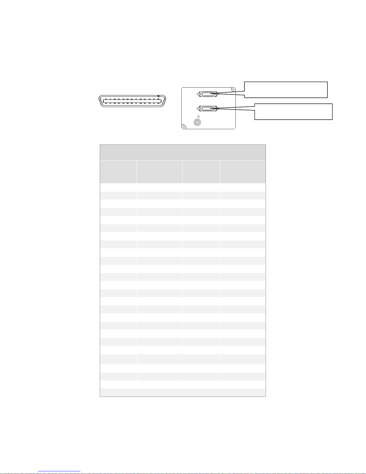
2.3 Connectors, Pinouts, and Cables
The camera uses a high-density 26-pin MDR26 connector for Camera Link control signals,
data signals, and serial communications, and a 6-pin Hirose connector for power.
Table 3: Camera Link Medium and Full Configuration
*Exterior Overshield is connected to the shells of the connectors on both ends.
**3M part 14X26-SZLB-XXX-0LC is a complete cable assembly, including connectors.
03-032-00493-14 Teledyne DALSA

15 Piranha 2 User’s Manual
Base Configuration
One Channel Link Chip + Camera Control +Serial
Communication
Camera Connector
Right Angle
Frame Grabber
Channel Link
Signal
1 1 inner shield
14
14
inner shield
2
25
X0-
15
12
X0+ 3 24
X1-
16
11
X1+ 4 23
X2-
17
10
X2+ 5 22
Xclk-
18 9 Xclk+
6
21
X3-
19 8 X3+ 7 20
SerTC+
20 7 SerTC-
8
19
SerTFG-
21 6 SerTFG+
9
18
CC1-
22 5 CC1+
10
17
CC2+
23 4 CC2-
11
16
CC3-
24 3 CC3+
12
15
CC4+
25 2 CC4-
13
13
inner shield
26
26
inner shield
Signal
Configuration
Pin
CC1
EXSYNC
9, 22
CC2
PRIN
10, 23
CC3
Spare
11, 24
CC4
Spare
12, 25
Table 4: Camera Link Base Configuration
Unused pairs should be terminated in 100 ohms at both ends of the cable.
Table 5: Camera Control Configuration
See Appendix B for the complete Camera Link configuration table, and refer to the
Knowledge Center page on the Teledyne DALSA Web site
(www.teledynedalsa.com/ mv/ knowledge/ appnotes.aspx) for the official Camera Link
documents.
03-032-00493-14 Teledyne DALSA

16 Piranha 2 User’s Manual
!
Hirose 6-pin Circular Male
5
4
6
2
3
1
Mating Part: HIROSE
HR10A-7P-6S
Pin
Description
Pin
Description
1
+12V to +15V
4
GND
2
+12V to +15V
5
GND
3
+12V to +15V
6
GND
PRIN
Indicates
High
Integration
Low
Pixel reset
IMPORTANT:
This camera uses the
falling edge of EXSYNC
to trigger line readout,
unlike previous DALSA
cameras, which used the
rising edge.
2.4 Power Supplies
The camera requires a single voltage input (+12V to +15V). The camera meets all
performance specifications using standard switching power supplies, although wellregulated linear supplies provide optimum performance. See the Performance
Specifications for current requirements.
When setting u p the cam era’s pow er su p p lies follow th ese gu id elin es:
• Protect the camera with a fast-blow fuse between power supply and camera.
• Do not use the shield on a multi-conductor cable for grou nd.
• Keep leads as short as possible to reduce voltage drop.
See section 1.3 for power requirements.
WARNING: It is extremely important that you apply the appropriate voltages to your camera.
Incorrect voltages will damage the camera. Protect the camera with a fast-blow fuse between
power supply and camera.
Visit http:/ / vfm.dalsa.com for a list of companies that make power supplies that meet
th e camer a’s requ ir em ents. Th e com pan ies listed sh ou ld n ot be consid ered th e on ly
choices. Many high quality supplies are available from other vendors. We assume no
responsibility for the use of these supplies.
2.5 Control Inputs, Camera Link
The camera accepts control inputs through the Camera Link MDR26F connector.
All inputs are optional. The camera ships in exposure mode 2 and with a 5 kHz line rate. All
Camera Control (CCx) signals are in a logic HIGH state.
Line rate can be set internally using the serial interface. Power-on rate is alw ays 9600
baud. Data rate for the 40MHz model is always 40MHz. Data rate for the 30MHz model is
always 30MHz.
The external control signals, EXSYNC and PRIN, are optional and enabled through the
serial interface.
PRIN
PRIN is an optional input signal used for exposure control (PRIN).
03-032-00493-14 Teledyne DALSA

17 Piranha 2 User’s Manual
Clocking Signal
Indicates
LVAL (high)
Outputting valid line
DVAL (high)
Valid data
STROBE (rising edge)
Valid data
EXSYNC (Triggers Line Readout)
EXSYNC is an optional input signal that can be used to trigger the line readout rate. This
camera u ses the falling edge of EXSYNC to trigger line readout.
Note: EXSYNC sh ou ld n ot be clocked fast er t h an the cam era’s specified m axim um line
rate. The camera ignores the EXSYNC pulse until it has completed reading the last line
out.
2.6 Data Bus, Camera Link
These signals indicate when data is valid, allowing you to clock the data from the camera
to your acquisition system. These signals are part of the Camera Link configuration and
you should refer to the Camera Link Implem entation Road Map, available from the
Knowledge Center page on the Teledyne DALSA website
(www.teledynedalsa.com/ mv/ knowledge/ appnotes.aspx) for the standard location of
these signals:
IMPORTANT: This cam era’s d ata sh ould be sampled on the rising edge of STROBE.
Digital Data
The camera digitizes internally to 10 bits and outputs either all 10 bits or the most
significant 8 bits in LVDS format on the Camera Link connector.
Note: Due to flat-field correction calculations, certain digital numbers will be unavailable
when outputting 10 bits with flat-field correction enabled (i.e. you will experience
missing codes).
03-032-00493-14 Teledyne DALSA

18 Piranha 2 User’s Manual
Location
Value
Description
1
A’s
By ensuring these values consistently toggle
between "aa" and "55", you can verify cabling
(i.e. no stuck bits)
2
5’s 3 A’s
4
4 bit counter LSB justified
Counter increments by 1. Use this value to
verify that every line is output
5
Line sum LSB
Use these values to help calculate line
average
6
Line sum MID
7
Line sum MSB
8 0 9 Pixels above threshold LSB
Monitor these values (either above or below
threshold) and adjust camera gain to keep
these values relatively constant. This
provides a basis for automatic gain control
(AGC)
10
Pixels above threshold
MSB
11
Pixels below threshold LSB
12
Pixels below threshold
MSB
13
Derivative line sum LSB
Use these values to focus the camera.
Generally, the greater the sum the greater the
image contrast
14
Derivative line sum Mid
15
Derivative line sum MSB
16 0
For information
on the test pattern
and end of line
sequence
commands, see
section 3.17
Generating Test
Patterns.
Test Pattern Pixels and End-of-line Sequence
To facilitate system-level debugging and verification of data path integrity, the camera
can generate a test pattern. The test pattern is a ramp from 0 to 255DN, then starts at 0
again. Use the test pattern to verify the proper timing and connections between the
camera and the frame grabber.
To alleviate post-processing, Piranha 2 offers an end-of-line sequence that provides basic
calculations including "line counter", "line average", "pixels above threshold", "pixels
below threshold", and "derivative line sum". These basic calculations are the center of
most automatic gain control (AGC) algorithms.
To further aid in debugging and cable/ data path integrity, the first six bits of the output
of the end-of-line sequence are "aa", "55", "aa". Refer to the table below.
03-032-00493-14 Teledyne DALSA
19 Piranha 2 User’s Manual
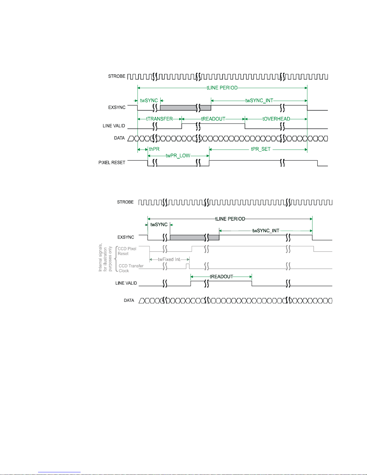
2.7 Timing
Figure 6. Piranha 2 Overview Timing Showing Input and Output Relationships
Figure 7. Piranha 2 Fixed (Programmed) Integration Timing with External EXSYNC
03-032-00493-14 Teledyne DALSA

20 Piranha 2 User’s Manual
Symbol
Definition
Min (ns)
Typ
(ns)
Max
(ns)
twSYNC
The minimum low width of the EXSYNC
pulse when not in SMART EXSYNC
mod e.
100
twSYNC
(SMART)
*
The minimum low width of the EXSYNC
pulse when in SMART EXSYNC modes to
guarantee the photosites are reset.
2,000
twSYNC_INT
The minimum width of the high pulse
w h en th e ―SMART EXSYNC‖ featu r e is
turned off
100
twSYNC_INT
(SMART)
*
Is the in teg r atio n tim e w h en th e ―SMART
EXSYNC‖ featu r e is a vailable an d tu rn ed
on. Note that the minimum time is
necessary to guarantee proper operation.
2,000
tLINE PERIOD
(t LP)
The minimum and maximum line times
mad e up of tTransfer, tREADOUT plus
tOVERHEAD to meet specifications.
53,190 (8K4T)
106,382 (8K2T)
40,485 (6K4T)
80,645 (6K2T)
27,624 (4K4T)
54,054 (4K2T)
28,248 (2K2T)
15,313 (1K2T)
106
tTransfer
The time from the reception of the falling
edge of EXSYNC to the rising edge of
LVAL when pretrigger is set to zero.
Pretrigger reduces the number of clocks to
th e risin g edge of LVAL b u t d oesn’t
change the time to the first valid pixel. If
the fixed integration time mode of
operation is available and selected then
the integration time is added to the
specified value.
1,420 +/ -50
twFixed Int.
Fixed Integration Time mode of operation
for variable exsync frequency.
800 t
LP
–
2,000
tREADOUT
Is the number of pixels per tap times the
read out clock period. Pretrigger = 0.
51,200 (8K4T)
102,400 (8K2T)
38,400 (6K4T)
76,800 (6K2T)
25, 600 (4K4T)
51,200 (4K2T)
25,600 (2K2T)
12,800 (1K2T)
tOVERHEAD
Is the number of pixels that must elapse
after the falling edge of LVAL before the
EXSYNC signal can be asserted. This time
is used to clamp the internal analog
electronics
540+/ -50
thPR
Applies when the PRIN exposure control
feature is enabled . The PRIN signal must
be held a minimum time after the
EXSYNC falling edge to avoid losing the
integrated charge
0
twPR_LOW
Minimum Low time to assure complete
2,000 +/ - 200
Table 6: Piranha 2 40MHz Timing (Fixed Integration Mode)
03-032-00493-14 Teledyne DALSA

21 Piranha 2 User’s Manual
Symbol
Definition
Min (ns)
Typ
(ns)
Max
(ns)
photosite reset
tPR_SET
The nominal time that the photo sites are
integrating. Clock synchronization will
lead to integration time jitter, which is
shown in the specification as +/ - values.
The user should command times greater
than these to ensure proper charge
transfer from the photosites. Failure to
meet this requirement may result in
blooming in the Horizontal Shift Register.
2,000+/ -200
Symbol
Definition
Min (ns)
Typ
(ns)
Max
(ns)
twSYNC
The minimum low width of the EXSYNC
pulse when not in SMART EXSYNC
mod e.
132
twSYNC
(SMART)
*
The minimum low width of the EXSYNC
pulse when in SMART EXSYNC modes to
guarantee the photosites are reset.
2,640
twSYNC_INT
The minimum width of the high pulse
w h en th e ―SMART EXSYNC‖ featu r e is
turned off
132
twSYNC_INT
(SMART)
*
Is the in teg r atio n tim e w h en th e ―SMART
EXSYNC‖ featu r e is a vailable an d tu rn ed
on. Note that the minimum time is
necessary to guarantee proper operation.
2,000
tLINE PERIOD
(t LP)
The minimum and maximum line times
mad e up of tTransfer, tREADOUT plus
tOVERHEAD to meet specifications.
140487 (8K2T)
70,170 (4K2T)
36,378 (2K2T)
19,483 (1K2T)
106
tTransfer
The time from the reception of the falling
edge of EXSYNC to the rising edge of
LVAL when pretrigger is set to zero.
Pretrigger reduces the number of clocks to
th e risin g edge of LVAL b u t d oesn’t
change the time to the first valid pixel. If
the fixed integration time mode of
operation is available and selected then
the integration time is added to the
specified value.
1,874 +/ -66
twFixed Int.
Fixed Integration Time mode of operation
for variable exsync frequency.
800 t
LP
–
2,000
tREADOUT
Is the number of pixels per tap times the
read out clock period. Pretrigger = 0.
138033 (8K2T)
33, 792 (4K4T)
67,584 (4K2T)
33,792 (2K2T)
16,896 (1K2T)
*SMART EXSYNC refers to exposure mode 4. Refer to section 3.9 Setting Line Rate and
Exposure Mode for further information on exposure modes.
Table 7: Piranha 2 30MHz Timing (Fixed Integration Mode)
Note: All values are preliminary for the Piranha 2 30MHz
03-032-00493-14 Teledyne DALSA

22 Piranha 2 User’s Manual
Symbol
Definition
Min (ns)
Typ
(ns)
Max
(ns)
tOVERHEAD
Is the number of pixels that must elapse
after the falling edge of LVAL before the
EXSYNC signal can be asserted. This time
is used to clamp the internal analog
electronics
712+/ -66
thPR
Applies when the PRIN exposure control
feature is enabled . The PRIN signal must
be held a minimum time after the
EXSYNC falling edge to avoid losing the
integrated charge
0
twPR_LOW
Minimum Low time to assure complete
photosite reset
2,640 +/ - 264
tPR_SET
The nominal time that the photo sites are
integrating. Clock synchronization will
lead to integration time jitter, which is
shown in the specification as +/ - values.
The user should command times greater
than these to ensure proper charge
transfer from the photosites. Failure to
meet this requirement may result in
blooming in the Horizontal Shift Register.
2,640+/ -264
2.8 Camera Link Serial Communication
Camera featu res can be con trolled th rou gh the Camera Lin k™ serial comm u nication
(LVDS, 9600 baud). The serial interface uses simple ASCII-based protocol. The following
chapter describes how to configure the camera using the serial interface.
03-032-00493-14 Teledyne DALSA

23 Piranha 2 User’s Manual
i
This chapter details the
most commonly used
commands. See
Appendix C for the
complete syntax and
command reference for
the camera’s serial
interface.
3
Software Interface:
How to Control the
Camera
3.1 Overview
All camera features can be controlled through the serial interface. The camera can also be
used without the serial interface after it has been set up correctly. Functions available
include:
• Controlling basic camera functions such as gain and sync signal source
• Camera calibration
• Measuring internal temperature and voltages
• Capturing video
• Generating a test pattern for debugging
The serial interface uses a simple ASCII-based protocol. The complete protocol is
described in Appendix C, Communications Protocol.
Online Help
For quick help, the camera can return all available commands and parameters through
the serial interface. To generate this list, send the command h to the camera.
Retrieving Camera Settings
To read current camera settings, send the command gcp. For an explanation of the
camera parameter screen, see section C6 Camera Parameter Screen on page 70.
3.2 Command Format
03-032-00493-14 Teledyne DALSA
• A carriage return (CR) end s each command.
• Values in square brackets are optional.
24 Piranha 2 User’s Manual
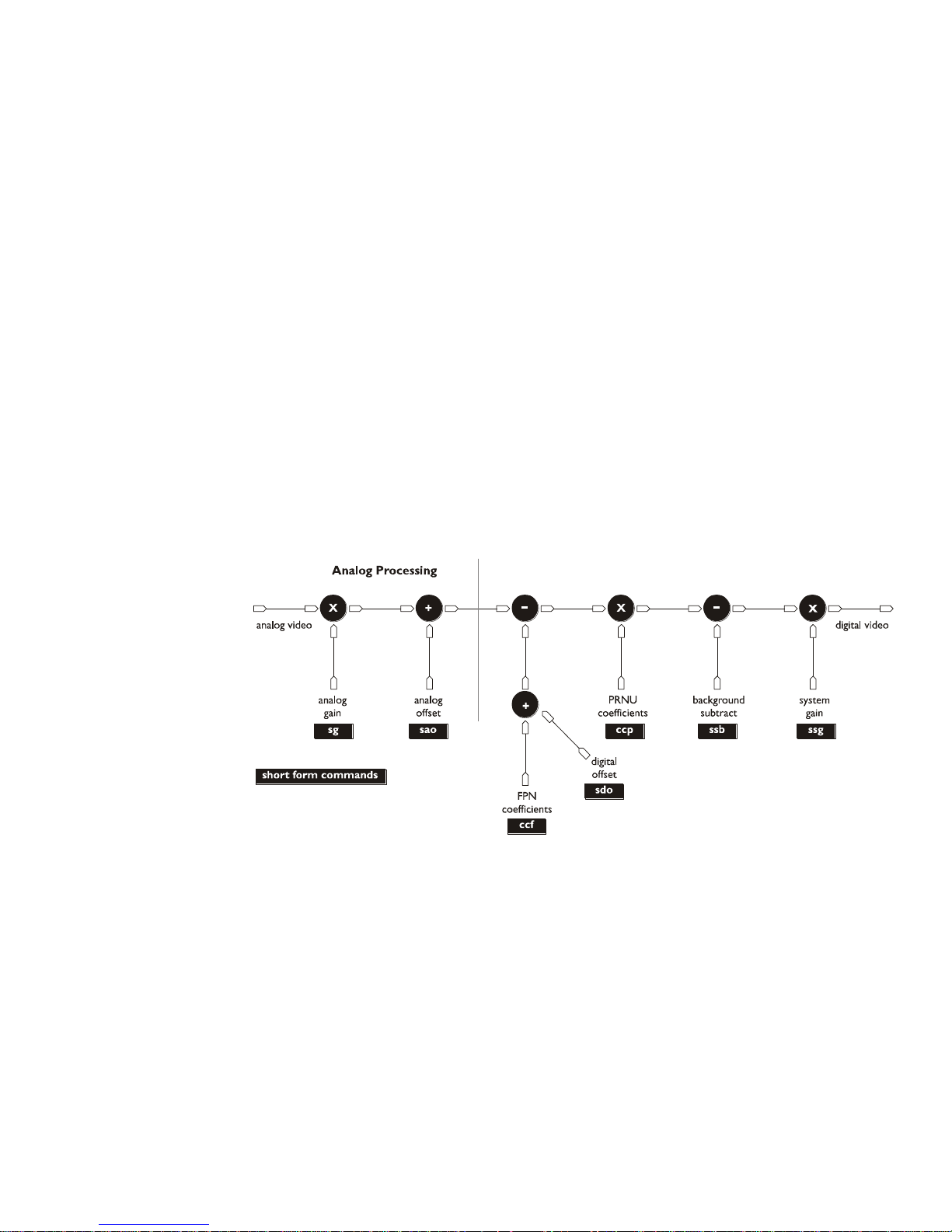
Digital Processing
• There are two methods for entering the command s: In long form each command is
written in its entirety. In short form, only a predefined abbreviation is required. The
manual uses the short form.
• The camera will answer each command with either "OK >" or "Error x: Error Message
>". The ">" is always the last character sent by the camera.
• The following parameters are used in the manual:
i = integer
f = float
s = string
t = tap
x1, x2 = pixel start and stop values
3.3 Processing Chain
The figure below is a simplified block diagram of the camera's processing chain. The
analog processing chain contains two elements–a gain stage and an offset stage. The
digital processing chain contains the FPN correction, PRNU correction, background
subtract, and a system gain stage. The software command s allow you to set and change
all the elements of the processing chain. This enables maximum processing flexibility
depending on your requirements.
In addition, the two elements of the analog processing chain, analog gain and analog
offset, can be adjusted to separate values in the calibrated and uncalibrated modes. For
example, the analog gain value can be set to –5db in calibrated mode and 6dB in
uncalibrated mode. When switching between calibrated and uncalibrated modes, the
camera automatically uses the corresponding value.
03-032-00493-14 Teledyne DALSA

25 Piranha 2 User’s Manual
write / restore
restore
Current
Session
Factory Settings
User Settings /
EEROM
3.4 Startup
When the camera is first started, it must perform several actions before it is ready for
imaging. This startup routine takes approximately 15 seconds, and follows this sequence:
1. Initializes the camera and all internal hardware.
2. Loads the last settings saved to non-volatile memory, including the last set of video
correction coefficients, if previously saved.
3. Restores user settings if previously saved, otherwise factory settings.
4. Performs a memory test and voltage test and reports an error if any occurred.
After this startup sequence is complete, the camera will return either the prompt "OK>" if
no error occurred, or an error code if a problem has been discovered.
3.5 Saving and Restoring Settings
The camera provides a number of commands for restoring, storing, and saving settings.
To restore the original factory settings, use the command rfs. The FPN and PRNU
coefficients are reset to 0.
To save all current settings to EEROM, use the command wus. The camera will
automatically restore the saved user settings when powered up. Note: While settings
are being written to nonvolatile memory, do not power down camera or camera
memory may be corrupted.
To save all current pixel coefficients to EEROM, use the command wpc.
To restore the last saved user settings and the FPN and PRNU coefficients, use the
command rus.
03-032-00493-14 Teledyne DALSA

26 Piranha 2 User’s Manual
Syntax:
sbr i
Syntax Elements:
i
Baud rate. Available baud rates are: 9600 (Default), 19200, 57600,
and 115200.
Notes:
Power-on rate is always 9600 baud.
The rc (reset camera) command will not reset the camera to the
pow er-on baud rate.
Example:
sbr 57600
Syntax:
sdm i
Syntax Elements:
i
See Table 8: Mode Selection Values below for allowable parameter
values.
Notes:
To obtain the current data mode, use the command gcp.
Example:
sdm 0
Mode
Description
0
8-bit, using A/ B/ C/ D ports for single processor configuration
1
10-bit, using A/ B/ C and D/ E/ F for single processor configuration
2
8-bit using ports A/ B and D/ E for dual processor configuration
3
10-bit, using A/ B/ C and D/ E/ F for dual processor configuration
3.6 Setting Baud Rate
To set the speed of the camera serial communication port, use the command:
3.7 Setting the Data Mode
To select the camera output mode, use the command:
In the table below, ports A-F refer to ports in the Camera Link specification.
Table 8: Mode Selection Values
To obtain the current data mode, use the command gcp.
03-032-00493-14 Teledyne DALSA
 Loading...