

Page 1
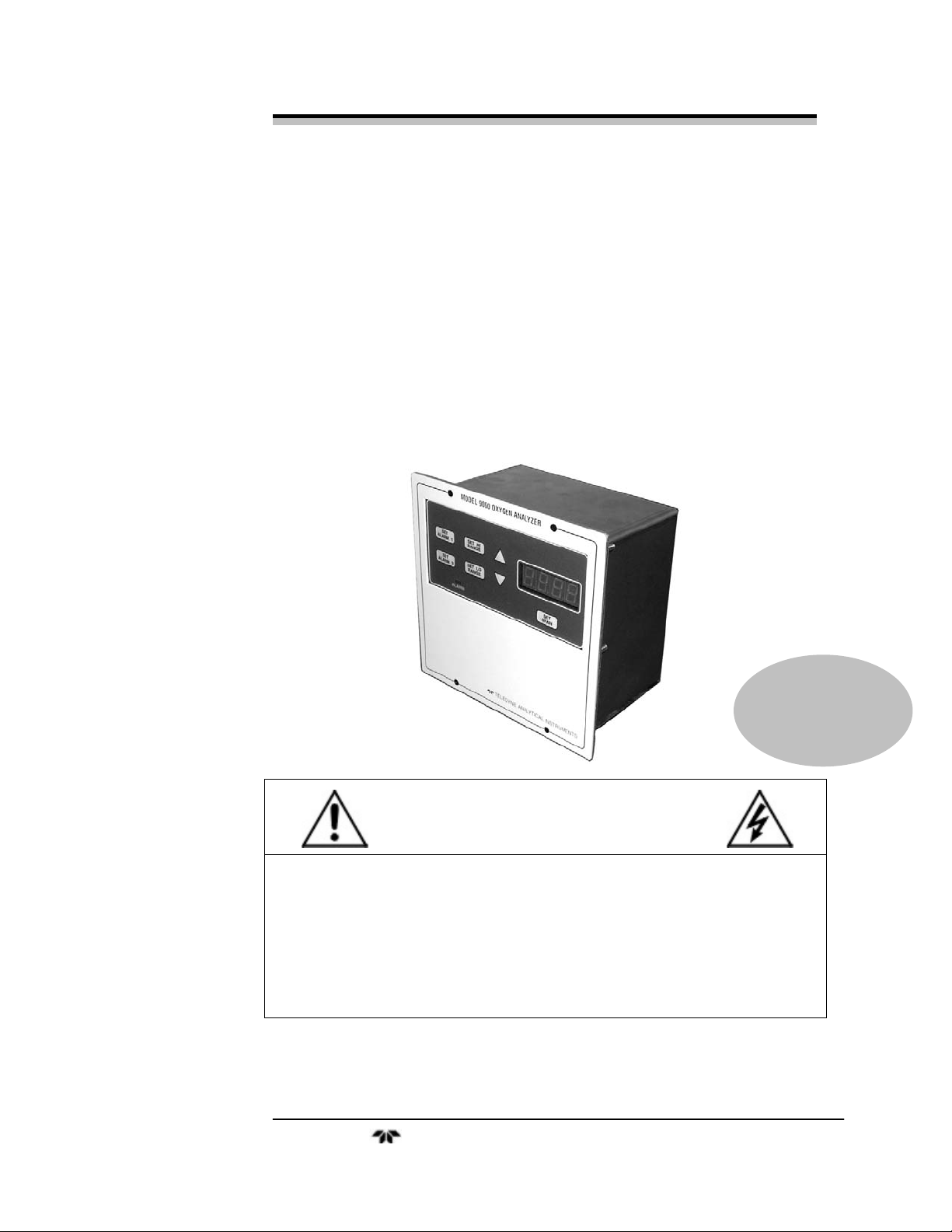
OPERATING INSTRUCTIONS FOR
Model 9060L
Percent Oxygen Analyzer
P/N M77713
ECO:
DANGER
Toxic gases and or flammable liquids may be present in this monitoring system.
Personal protective equipment may be required when servicing this instrument.
Hazardous voltages exist on certain components internally which may persist
for a time even after the power is turned off and disconnected.
Only authorized personnel should conduct maintenance and/or servicing.
Before conducting any maintenance or servicing, consult with authorized
supervisor/manager.
Teledyne Analytical Instruments
Page 2

Model 9060L
Copyright © 2005 Teledyne Instruments/ Analytical Instruments
All Rights Reserved. No part of this manual may be reproduced, transmitted, transcribed,
stored in a retrieval system, or translated into any other language or computer language in
whole or in part, in any form or by any means, whether it be electronic, mechanical,
magnetic, optical, manual, or otherwise, without the prior written consent of Teledyne
Instruments/ Analytical Instruments, 16830 Chestnut Street, City of Industry, CA 91749-
1580.
Warranty
This equipment is sold subject to the mutual agreement that it is warranted by us free from
defects of material and of construction, and that our liability shall be limited to replacing or
repairing at our factory (without charge, except for transportation), or at customer plant at
our option, any material or construction in which defects become apparent within one year
from the date of shipment, except in cases where quotations or acknowledgements provide
for a shorter period. Components manufactured by others bear the warranty of their
manufacturer. This warranty does not cover defects caused by wear, accident, misuse,
neglect or repairs other than those performed by TI/AI or an authorized service center. We
assume no liability for direct or indirect damages of any kind and the purchaser by the
acceptance of the equipment will assume all liability for any damage which may result from
its use or misuse.
We reserve the right to employ any suitable material in the manufacture of our apparatus,
and to make any alterations in the dimensions, shape or weight of any parts, in so far as
such alterations do not adversely affect our warranty.
Important Notice
This instrument provides measurement readings to its user, and serves as a tool by which
valuable data can be gathered. The information provided by the instrument may assist the user
in eliminating potential hazards caused by his process; however, it is essential that all
personnel involved in the use of the instrument or its interface, with the process being
measured, be properly trained in the process itself, as well as all instrumentation related to it.
The safety of personnel is ultimately the responsibility of those who control process
conditions. While this instrument may be able to provide early warning of imminent
danger, it has no control over process conditions, and it can be misused. In particular, any
alarm or control systems installed must be tested and understood, both as to how they
operate and as to how they can be defeated. Any safeguards required such as locks, labels,
or redundancy, must be provided by the user or specifically requested of TI/AI at the time
the order is placed.
Therefore, the purchaser must be aware of the hazardous process conditions. The purchaser
is responsible for the training of personnel, for providing hazard warning methods and
instrumentation per the appropriate standards, and for ensuring that hazard warning devices
and instrumentation are maintained and operated properly.
Teledyne Instruments/ Analytical Instruments, the manufacturer of this instrument, cannot
accept responsibility for conditions beyond its knowledge and control. No statement
expressed or implied by this document or any information disseminated by the
manufacturer or its agents, is to be construed as a warranty of adequate safety control under
the user’s process conditions.
Teledyne Analytical Instruments ii
Page 3

Percent Oxygen Analyzer
Specific Model Information
Instrument Serial Number: _______________________
Instrument Range: _______________
Calibrated for: _______________
Background Gas: _______________
Zero Gas: _______________
Span Gas: _______________
Teledyne Analytical Instruments iii
Page 4
Model 9060L
Safety Messages
Your safety and the safety of others is very important. We have
provided many important safety messages in this manual. Please read
these messages carefully.
A safety message alerts you to potential hazards that could hurt you
or others. Each safety message is associated with a safety alert symbol.
These symbols are found in the manual and inside the instrument. The
definition of these symbols is described below:
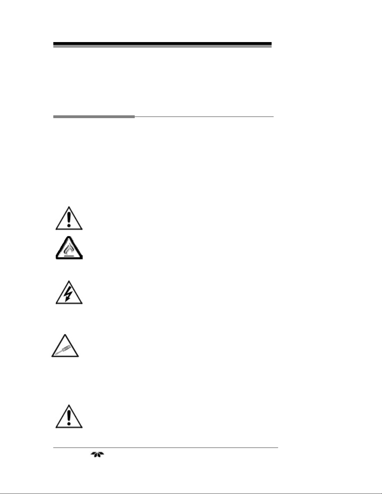
GENERAL WARNING/CAUTION: Refer to the instructions
for details on the specific danger. These cautions warn of
specific procedures which if not followed could cause bodily
Injury and/or damage the instrument.
CAUTION: HOT SURFACE WARNING: This warning is
specific to heated components within the instrument. Failure
to heed the warning could result in serious burns to skin and
underlying tissue.
WARNING: ELECTRICAL SHOCK HAZARD: Dangerous
voltages appear within this instrument. This warning is
specific to an electrical hazard existing at or nearby the
component or procedure under discussion. Failure to heed this
warning could result in injury and/or death from
electrocution.
Technician Symbol: All operations marked with this symbol
are to be performed by qualified maintenance personnel only.
No
Symbol
CAUTION: THE ANALYZER SHOULD ONLY BE USED FOR THE
NOTE: Additional information and comments regarding a
specific component or procedure are highlighted in the form
of a note.
PURPOSE AND IN THE MANNER DESCRIBED IN
THIS MANUAL.
Teledyne Analytical Instruments iv
Page 5

Percent Oxygen Analyzer
IF YOU USE THE ANALYZER IN A MANNER OTHER
THAN THAT FOR WHICH IT WAS INTENDED,
UNPREDICTABLE BEHAVIOR COULD RESULT
POSSIBLY ACCOMPANIED WITH HAZARDOUS
CONSEQUENCES.
This manual provides information designed to guide you through
the installation, calibration operation and maintenance of your new
analyzer. Please read this manual and keep it available.
Occasionally, some instruments are customized for a particular
application or features and/or options added per customer requests.
Please check the front of this manual for any additional information in
the form of an Addendum which discusses specific information,
procedures, cautions and warnings that may be peculiar to your
instrument.
Manuals do get lost. Additional manuals can be obtained from
TI/AI at the address given in the Appendix. Some of our manuals are
available in electronic form via the internet. Please visit our website at:
www.teledyne-ai.com.
Teledyne Analytical Instruments v
Page 6

Model 9060L
Table of Contents
List of Figures ............................................................................viii
List of Tables................................................................................ix
Introduction................................................................................. 11
1.1 Overview 11
1.2 Main Features of the Analyzer 11
1.3 Front Panel Description 12
1.4 Rear Panel Description 13
Operational Theory.....................................................................15
2.1 Introduction 15
2.2 Oxygen Probe, Sensor, and Heater 15
2.2.1 Probe Configuration 17
2.2.2 The Zirconia Sensor 18
2.2.3 Heater 19
2.3 Applications Not at Atmospheric Pressure 20
2.4 Sensor Impedance 20
2.5 Electronics 20
2.5.1 General 20
2.5.2 Signal Processing 21
Installation................................................................................... 23
3.1 Unpacking the Analyzer 23
3.2 Control Unit Installation 23
3.3 9060L Oxygen Probe Installation 23
3.4 Electrical Connections 25
3.4.1 Primary Input Power 25
3.4.2 Analog Outputs 26
3.4.3 Alarm Relays 26
Teledyne Analytical Instruments vi
Page 7

Percent Oxygen Analyzer
3.4.1 Oxygen Probe Connections 28
3.5 Installation Checklist 29
Operation .....................................................................................31
4.1 Introduction 31
4.2 Using the Function and Data Entry Buttons 32
4.3 Setting the Analysis Ranges 32
4.3.1 HI Range 33
4.3.2 LO Range 33
4.4 Setting the Alarm Setpoints 33
4.4.1 Set Alarm 1 (HI alarm) 33
4.4.2 Set Alarm 2 (LO alarm ) 34
4.4.3 Sensor Fail Alarm 34
4.5 Selecting a Fixed Range or Autoranging 34
4.6 Oxygen Calibration 35
4.6.1 Span Calibration 35
4.6.2 Air Calibration 37
4.7 Supplementary Information 37
4.8 Probe Temperature 37
4.8.1 Low Temperature 38
4.8.2 Open Thermocouple 38
4.9 Error Messages 38
Maintenance.................................................................................41
5.1 Replacing the Fuse 41
Appendix......................................................................................43
A.1 Specifications 43
A.2 Probe Specifications 44
A.3 Spare Parts List 45
Email: ask_tai@teledyne.comA.4 Reference Drawing 45
A.4 Reference Drawing 46
A.5 Probe or Sensor EMF Tables 46
Index.............................................................................................49
Teledyne Analytical Instruments vii
Page 8

Model 9060L
List of Figures
Figure 1-1: Front Panel................................................................12
Figure 1-2 Rear Panel................................................................... 14
Figure 2-1: Model 9060L Oxygen Probe.......................................16
Figure 2-2: Model 9060L Probe.....................................................17
Figure 2-3: Internal Structure of the Zirconia Sensor and Probe...18
Figure 2-3: Signal Processing Block Diagram...............................21
Figure 3-1: Oxygen Probe Mounting.............................................25
Figure 3-2: Model 9060L Rear panel............................................. 26
Figure 3-3: Contact ID for FAILSAFE Relay Operation................. 27
Figure 3-4:Model 9060L Heated Probe Cable Connection ............ 28
Figure 3-5: Connections to Probe .................................................29
Figure 4-1: Front Panel Controls and Indicators............................31
Figure 4-2: Calibration Port on Probe Head.................................. 35
Figure 5-1: AC Fuse Replacement................................................ 41
Teledyne Analytical Instruments viii
Page 9

Percent Oxygen Analyzer
List of Tables
Table 2-1: Probe Options ..............................................................17
Teledyne Analytical Instruments ix
Page 10
Model 9060L
DANGER
COMBUSTIBLE GAS USAGE
This is a general purpose instrument designed for use in a
non-hazardous area. It is the customer's responsibility to
ensure safety especially when combustible gases are being
analyzed since the potential of gas leaks always exist.
The customer should ensure that the principles of operating
this equipment are well understood by the user. Misuse of
this product in any manner, tampering with its components,
or unauthorized substitution of any component may
adversely affect the safety of this instrument.
WARNING
Since the use of this instrument is beyond the control of
Teledyne Instruments/ Analytical Instruments, referred as
TI/AI, no responsibility by TI/AI, its affiliates, and agents for
damage or injury from misuse or neglect of this equipment is
implied or assumed.
Teledyne Analytical Instruments x
Page 11

Percent Oxygen Analyzer Introduction
Introduction
1.1 Overview
The Teledyne Instruments/ Analytical Instruments (TI/AI) Model
9060L is a microprocessor-based percent oxygen analyzer for real-time
measurement of the percent of oxygen in inert gases, or in a wide variety
of gas mixtures. It features simple operation, fast response, and a
compact, rugged construction. Typical applications of the Model 9060L
are monitoring kilns, boilers, and flue gas at temperature from ambient
up to 1400°C (2550°F).
1.2 Main Features of the Analyzer
The main features of the analyzer include:
• High resolution, accurate readings of oxygen content from 0-1 %
through 0-100 % O2. Large, bright, light-emitting-diode meter
readout.
• Simple pushbutton controls.
• State of the art zirconia sensor.
• Longer life probes with greater resistance to thermal shock and
mechanical damage during installation and start-up.
• Fast response and recovery time.
• Microprocessor based electronics: 8-bit CMOS microprocessor
with on-board RAM and 16 KB ROM.
• Two user selectable ranges (from 0-1% through 0-100%) allow
best match to user’s process and equipment.
• Air-calibration range for convenient spanning at 20.9 %.
• Operator can select autoranging, which allows the analyzer to
automatically select the proper preset range for a given
measurement, or lock the analyzer onto a single range.
Teledyne Analytical Instruments 11
Page 12
Introduction Model 9060L
• Two concentration alarms with adjustable setpoints.
• A failure alarm.
• Three analog outputs: two for measurement (0–10VDC, and
negative ground 4–20 mA DC) and one for range identification
(0-10VDC).
• Compact and rugged control unit with flush-panel case.
Designed for indoor use.
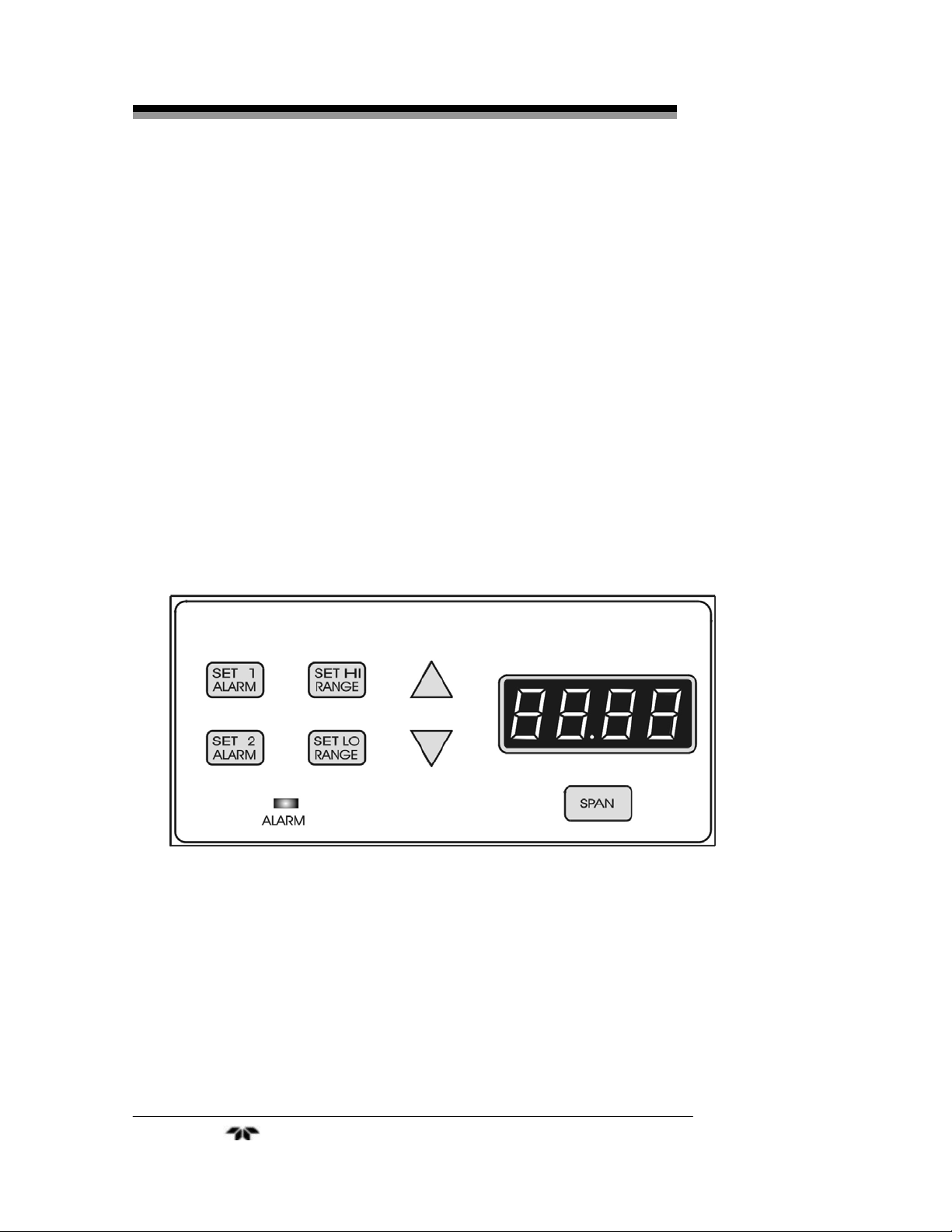
1.3 Front Panel Description
All controls and displays except the power switch are accessible
from the front panel. See Figure 1-1. The front panel has seven
pushbutton membrane switches, a digital meter, and an alarm indicator
LED for operating the analyzer. These features are described briefly
here and in greater detail in Chapter 4, Operation.
Figure 1-1: Front Panel
Function Keys: Seven pushbutton membrane switches are used to
select the function performed by the analyzer:
• Set Alarm 1 Sets the concentration at which alarm 1
activates upon rising above the threshold
(HI alarm).
Teledyne Analytical Instruments 12
Page 13

Percent Oxygen Analyzer Introduction
• Set Alarm 2 Sets the concentration at which alarm 2
activates upon dropping below the
threshold (LO alarm).
• Set HI Range Set the high analysis range for the
instrument (up to 0-100%).
• Set LO Range Set the low analysis range for the
instrument (down to 0-1%).
• Span Span calibrate the analyzer.
Data Entry Keys: Two pushbutton membrane switches are used to
manually change measurement parameters of the instrument as they are
displayed on the LED meter readout:
• Up Arrow Increment values of parameters upwards
as they are displayed on the LED readout.
• Down Arrow Increment values of parameters
downwards as they are displayed on the
LED readout.
Digital LED Readout: The digital display is a LED device that
produces large, bright, 7-segment numbers that are legible in any
lighting environment. It has two functions:
• Meter Readout As the meter readout, it displays the oxygen
concentration currently being measured.
• Measurement Parameters Readout The parameter readout
displays user-defined alarm setpoints, ranges, span calibration
point when they are being checked or changed, and probe
temperature on demand.
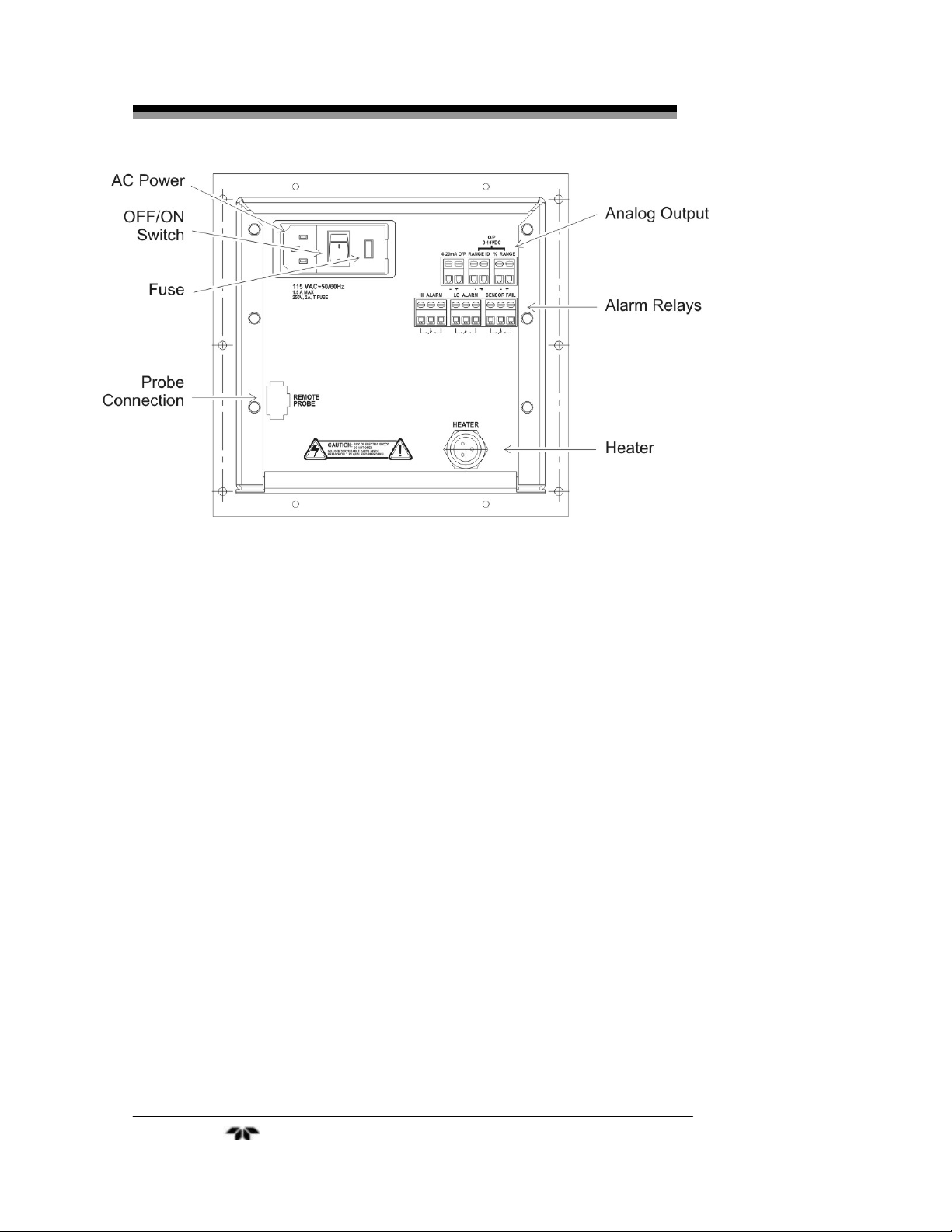
1.4 Rear Panel Description
The rear panel contains the electrical input and output connectors.
The connectors are described briefly here and in detail in the Installation
chapter of this manual.
Teledyne Analytical Instruments 13
Page 14
Introduction Model 9060L
Figure 1-2 Rear Panel
• Power Connection 110 VAC at 50/60 Hz. The connector
housing includes the fuse holder and the
power switch. (220VAC is optional via
setting an internal switch).
Fuse Holder: Replacing the fuse is
described in Chapter 5, Maintenance.
I/O Power Switch: Turns the instrument
power ON (1) or OFF (0).
• Analog Outputs 0–10 VDC concentration output.
0–10 VDC range ID (or optional
overrange) output.
4–20 mA DC concentration output,
negative ground.
• Alarm Connections Alarm 1 (HI alarm), Alarm 2 (LO alarm),
and Probe Failure Alarm connections.
• Sensor Connector For connecting the probe’s Oxygen
sensor.
• Heater Connector For connecting the probe’s heater
Teledyne Analytical Instruments 14
Page 15

Percent Oxygen Analyzer Operational Theory
Operational Theory
2.1 Introduction
The analyzer is composed of two subsystems:
1. Oxygen probe
2. Control unit with signal processing, display and controls
The oxygen probe can be heated or unheated. It delivers the sample
gas to a state-of-the-art zirconium sensor which translates the amount of
oxygen present into a millivolt output.
The control unit processes the sensor output and translates it into
electrical concentration, range, and alarm outputs, and a percent oxygen
meter readout. It contains a micro-controller that manages all signal
processing, input/output, and display functions for the analyzer.
2.2 Oxygen Probe, Sensor, and Heater
TI/AI oxygen probes and sensors employ state-of-the-art zirconia
sensors and advanced materials. They provide the following benefits:
• Improved control due to fast response time—typically less than
four seconds.
• Cost-efficient design provides improved reliability.
• Longer-life probes with greater resistance to corrosion from
sulphur and zinc contaminants in a flue gas.
• Low cost replacement reduces maintenance.
• Reduced probe breakage due to greater resistance to thermal
shock and mechanical damage during installation and startup.
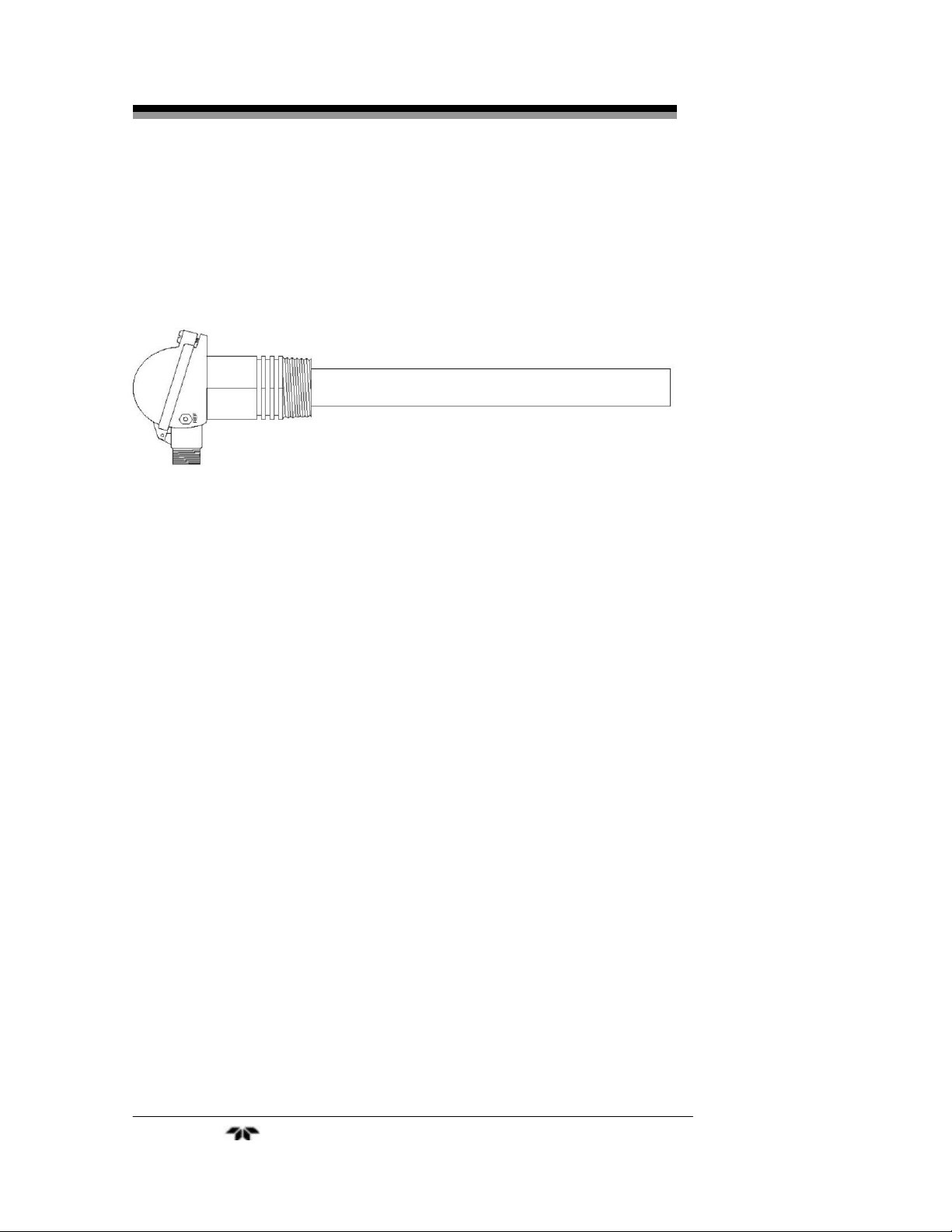
The 9060L probes or sensors are simple to install and maintain. All
models provide direct measurement of oxygen level. Figure 2-1 shows a
typical oxygen probe. Probe specifications are listed in the Appendix of
this manual and installation is covered in Section 3.
Teledyne Analytical Instruments 15
Page 16
Operational Theory Model 9060L
All Teledyne oxygen probe or sensors are designed and
manufactured to exacting standards of performance and reliability and are
the result of extensive research and development. Teledyne Analytical
Instruments provides worldwide application and after sales support for its
oxygen probes, sensors and analyzers.
Figure 2-1: Model 9060L Oxygen Probe
The probe assembly provides a means of exposing the zirconia
sensor to the atmosphere to be measured with sensor. It also provides for
means of interfacing the sensor, thermocouple and heater wires with the
control unit. Reference air is fed via the top plug for unheated probes or
by a separate gas thread connection for heated probes. Connections are
provided on probes for an in-situ gas calibration check. If required, an
air purge can be admitted via the calibration gas check entry. The outer
sheath of probes is either metal or ceramic, depending on the
application. Calibration check can be achieved on 9060LEX sensors
using a three way solenoid which blocks the sample and at the same
time admits a calibration gas to the sensor. As mentioned above, probe
purging for removing any dust build up can be achieved in the same
way.
In-situ zirconia oxygen probes will give a lower oxygen reading
than a sampled gas measurement on a chromatograph or paramagnetic
analyzer because the flue gas contains a significant level of water vapor
and a sampling system removes the water vapor through condensation.
The oxygen content then appears as a higher percentage of the
remaining gas. For example: If the gas contained five parts oxygen and
fifteen parts moisture, removing the moisture would leave the oxygen at
5.88%. This phenomena will depend on the fuel and the completeness
of combustion. They are common to all zirconia oxygen sensors.
Teledyne Analytical Instruments 16
Page 17
Percent Oxygen Analyzer Operational Theory
Probes of 1000 mm (40”) normally have sufficient length for any
installation. Customers requiring probes longer than 1500 mm (59”) are
supplied with a flow guide tube that uses the flue velocity to pull flue
gas through a filter at the sensing tip and exhaust it near the flue wall.
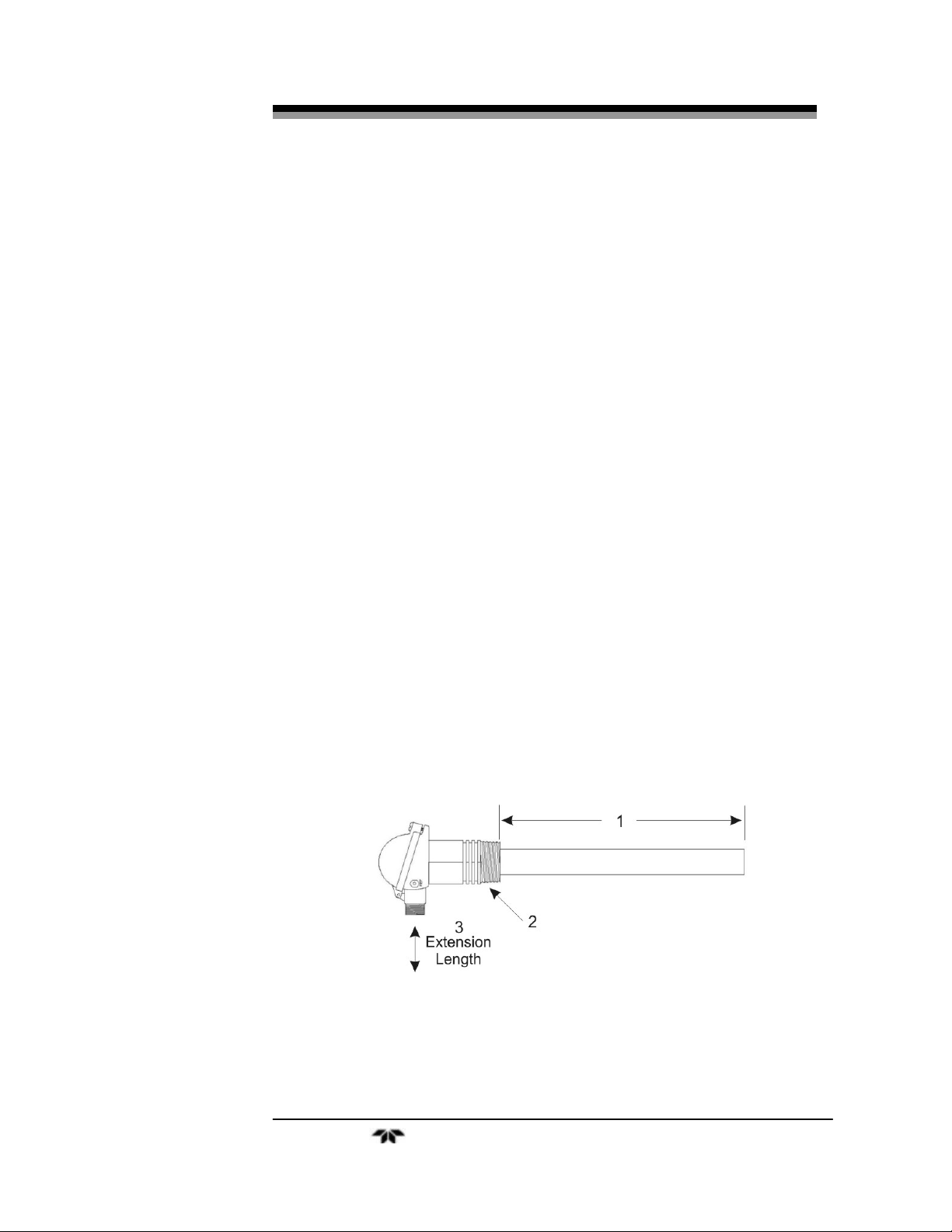
2.2.1 Probe Configuration
The probe can be configured in a variety of ways to suit the
analytical environment. Figure 2-1 shows the most common
configurable items of the probe. Not indicated is the actual
thermocouple sensing element, however, see Table 2-1. You can choose:
1. Probe insertion length (from process end of mounting thread to
probe sensing tip). See Figure 2-2.
2. Mounting thread (process connection), BST or NPT (for size of
thread refer to specifications).
3. Lagging extension length, if required.
Table 2-1 indicates typical probe options.
Table 2-1: Probe Options
Probe Length Thermocouple Sheath Thread
250 mm (10”) Type K max 900°C (1560°F) 316 SS max 850°C (1560°F) BST or NPT
350 mm (14”) Inconel
500 mm (20”)
750 mm (30”)
1000 mm (40”)
The Inconel option has all
inconel wetted parts except for
the ceramic sensor and viton
‘o’ rings
Figure 2-2: Model 9060L Probe
Teledyne Analytical Instruments 17
Page 18

Operational Theory Model 9060L
2.2.2 The Zirconia Sensor
Input to the analyzer is obtained from a solid electrolyte oxygen
probe containing a zirconia element and thermocouple. The probe is
designed to be inserted into a boiler or furnace exit gas flue or similar
process. The 9060LEX sensor is designed to be installed outside of the
flue or process. Sampling lines and filters are not required for in-situ
probes but they are required for 9060LEX sensors. When a sampling
line is required, the gas typically flows to the sensor under process
pressure. In applications where the process pressure is negative or
neutral, a suction pump will be required. A reference air pump is not
provided in the Model 9060L Oxygen Analyzer. The internal
construction of a probe or sensor is shown in Figure 2-3.
Figure 2-3: Internal Structure of the Zirconia Sensor and Probe
Heater control in the Model 9060L Oxygen Analyzer consists of a
time proportioning temperature controller and solid state relay so that
the thermocouple junction is controller to over 700°C (1300°F). Probes
operating in a combustion environment above 650°C (1200°F) do not
Teledyne Analytical Instruments 18
Page 19

Percent Oxygen Analyzer Operational Theory
require a heater. When the outside and inside of the sensor are exposed
to different oxygen partial pressures, an EMF (E) is developed which
obeys the Nernst equation:
log
⎛
⎜
e
⎜
⎝
Inside )(PO
2
Outside )(PO
2
RT
ts)E(millivol
=
4F
⎞
⎟
⎟
⎠
where T is the temperature (K) at the disc (>650°C (1200°F)), R is the
gas constant. F is the Faraday constant and (PO2) Inside and (PO2)
Outside are the oxygen partial pressures at the inner and outer electrodes
respectively with the higher oxygen partial pressure being positive.
If dry air at atmospheric pressure, (21% oxygen) is used as a
reference at the inner electrode, the following equations are obtained:
2
−
×=
⎛
⎜
log T 10154.2ts)E(millivol
e
⎜
⎝
21.0
Outside )PO(
2
⎞
⎟
⎟
⎠
Transposing this equation:
46.421E-
2
=
⎛
EXP 0.21(ATM) Outside )%O(
⎜
⎝
⎞
⎟
T
⎠
The 9060L transmitter solves this equation which is valid above
650°C (1200°F). Either the probe heater or the process maintains the
sensor temperature at this level.
2.2.3 Heater
CAUTION: DANGEROUS VOLTAGE (120 VAC) EXISTS WITHIN
THE PROBE OR HEATER AND PRESENTS AN
ELECTRICAL SHOCK HAZARD TO MAINTENANCE
PERSONNEL. ALWAYS DISCONNECT THE PROBE
FROM THE ANALYZER BEFORE WORKING WITH
THE PROBE, SENSOR, OR HEATER.
THE EARTH CONNECTION (GREEN WIRE) FROM
Teledyne Analytical Instruments 19
Page 20

Operational Theory Model 9060L
THE PROBE/SENSOR MUST ALWAYS BE
CONNECTED TO EARTH.
Power to the heater is supplied directly from the main power
source, and the temperature is initially controlled above 700°C (1300°F)
after power up.
2.3 Applications Not at Atmospheric Pressure
For high and low pressure applications where the pressure at the
point of measurement is significantly above or below atmospheric
pressure, compensation must be applied. The Model 9060L does not
incorporate a pressure sensor thus no compensation is performed. This
factor must be considered when reading concentration from the display
under high or low pressure monitoring conditions.
2.4 Sensor Impedance
The zirconia sensor impedance is a basic measurement of the
reliability of the oxygen reading. A probe or sensor with a high
impedance reading will eventually produce erroneous signals. The
analyzer checks the zirconia sensor impedance every 5 minutes and if
the impedance is above the maximum level for a specific temperature
then the impedance alarm will be activated. Typical sensor impedance
is 1 KΩ to 8 KΩ at 720°C (1320°F).
2.5 Electronics
2.5.1 General
The signal processing uses an Intel® micro-controller with on-board
RAM and ROM to control all signal processing, input/output, and
display functions for the analyzer. System power can be either 120 or
220 VAC depending on the position of an internal switch.
The power supply circuitry and temperature controller circuitry are
on the Power Supply PCB, which is mounted vertically, just behind the
rear panel of the control unit.
The signal processing electronics including the sensor amplifier,
micro-controller, analog to digital, and digital to analog converters are
Teledyne Analytical Instruments 20
Page 21
Percent Oxygen Analyzer Operational Theory
located on the Main PCB, which is mounted vertically, just behind the
front panel of the control unit.
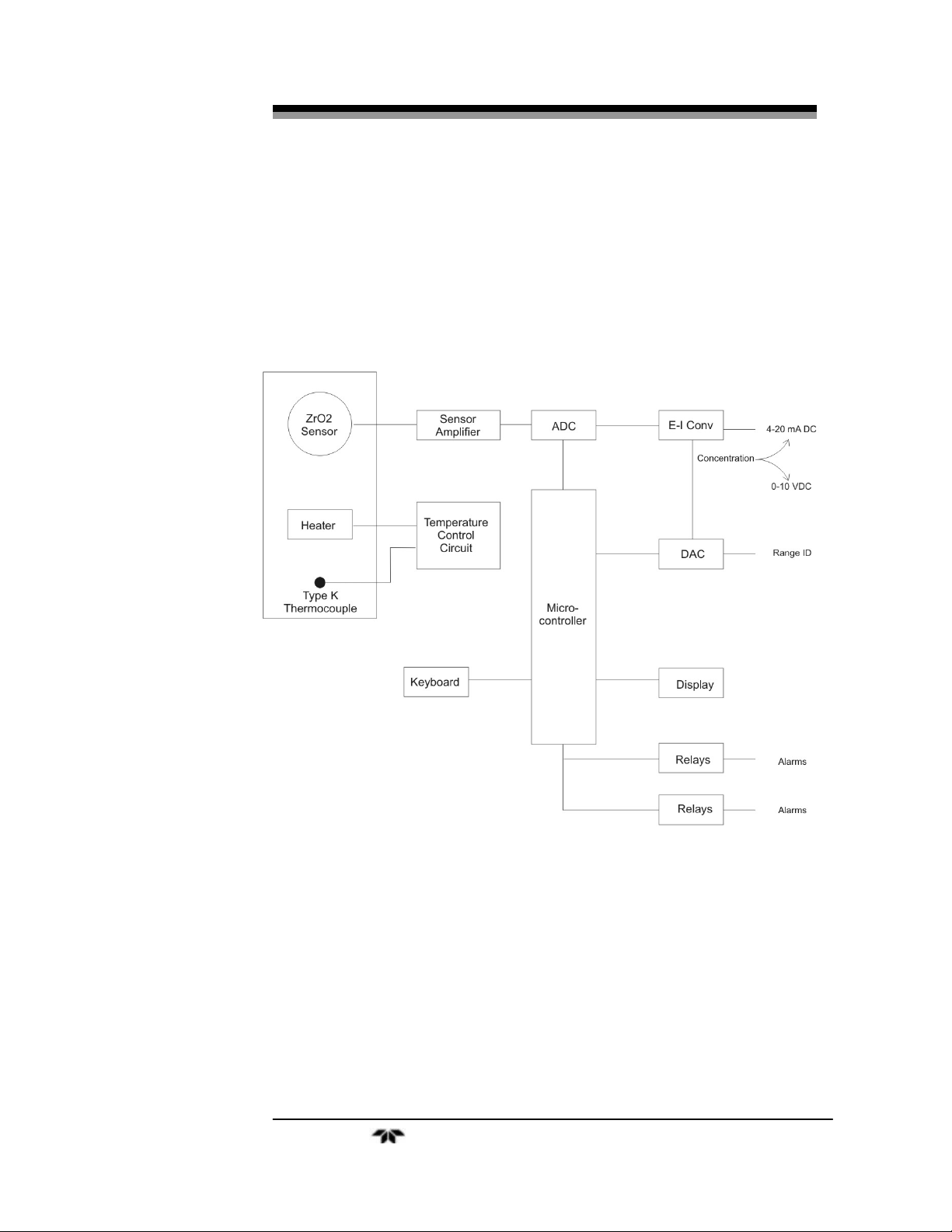
2.5.2 Signal Processing
Figure 2-3 is a block diagram of the signal processing electronics
described below.
Figure 2-3: Signal Processing Block Diagram
In the presence of oxygen the sensor generates a millivolt potential
which is fed to a voltage amplifier. The output from the sensor amplifier
is sent to an analog to digital converter (ADC), and the resulting digital
concentration signal is passed to the micro-controller. The ADC has a
second channel which monitors the temperature of the probe.
Teledyne Analytical Instruments 21
Page 22

Operational Theory Model 9060L
The digital concentration signal along with input from the front
panel buttons (KEYBOARD) is processed by the micro-controller, and
appropriate output signals are directed to the display and alarm relays.
The same digital information is also sent to a 12-bit digital to analog
converter (DAC) that produces the 0-10 VDC analog concentration
signal and the 0-10 VDC analog range ID output. A current to voltage
converter (E–I CONV) produces the 4-20 mA DC analog concentration
signal.
Teledyne Analytical Instruments 22
Page 23
Percent Oxygen Analyzer Installation
Installation
Installation of the analyzer includes:
1.
Unpacking the system.
2.
Mounting the control unit.
3.
Installing the probe.
4.
Making electrical connections.
5.
Testing the installation.
CAUTION: READ THIS CHAPTER IN ITS ENTIRETY BEFORE
INSTALLING THE SYSTEM.
FOR INDOOR USE ONLY.
3.1 Unpacking the Analyzer
As soon as you receive the instrument, carefully unpack and inspect
the control unit, and any included accessories for damage. Immediately
report any damage to the shipping agent. The analyzer is shipped with
all the materials you need to install and prepare the system for operation.
3.2 Control Unit Installation
The 9060L control unit is designed to be panel mounted in a
general purpose, indoor area, away from moisture and the elements. The
unit should be installed at viewing level in a sheltered area.
Refer to the Outline Diagram D-77712 in the Appendix for the
physical dimensions of the analyzer.
3.3 9060L Oxygen Probe Installation
To install the probe, weld a BSP or NPT socket to the flue in a
suitable position for flue gas sensing. For the correct size of socket refer
to probe specifications located in the Appendix.
Teledyne Analytical Instruments 23
Page 24
Installation Model 9060L
Note: Mount the probe as close to the combustion source as
possible. This reduces the lag time inherent in the
sampling process and results in better control.
The probe has a typical response time of less than four seconds, so
most of the delay time is associated with the transit time of the gas from
the point of combustion to the point of sensing.
Probes can be mounted at any angle. When feasible, a vertical
installation with the probe facing vertically downwards will eliminate
the need for a filter. This is especially useful for processes with
particulates in the flue gas. If a vertical mounting is not possible under
these conditions, a filter may be necessary. This may require periodic
filter replacement depending on the severity of the process.
If a flow guide tube is used (heated probes only), it is important that
the fin points directly downstream. If the exact flow direction is not
known, use a wind vane that can be made from a piece of wire and flat
metal. If the flow guide tube is installed facing the wrong direction for
any period, the suction filter may block with flue gas dust particles.
The maximum temperature for an unsupported flow guide tube is
750°C (1380°F). Above this temperature, provide a support and flanged
flexible rubber joint as shown in Figure 3-1. The maximum temperature
of a supported flow guide tube is 900°C (1650°F).
When installing a probe into a hot environment, slide the probe in
slowly to avoid thermal shock to the internal ceramic parts. If the flue
gas is 1000°C (1830°F), it should take approximately ten minutes to
install a 500 mm (20”) probe, moving it in steps of about 20 mm (1”).
CAUTION: IT IS IMPORTANT THAT THERE ARE NO AIR LEAKS
UPSTREAM OF THE OXYGEN SENSING POINT,
OTHERWISE THERE WILL BE A HIGH OXYGEN
READING.
If the probe is to be installed on a bend in the flue, it is best to
locate it on the outer circumference of the bend to avoid dead pockets of
flue gas flow. While the standard 9060L probe with a ‘U’ length of 250
mm (10”) will suit most low temperature flue applications, it is
occasionally necessary to have a longer probe with the sensing tip in the
center of the flue gas stream.
Although it is rare, occasionally a probe may sense oxygen vastly
different from the average reading in the flue gas. If it occurs, move the
Teledyne Analytical Instruments 24
Page 25

Percent Oxygen Analyzer Installation
probe or install a longer probe. This is normally caused by stratification
of the flue gas.
Figure 3-1: Oxygen Probe Mounting
3.4 Electrical Connections
Figure 3-1 shows the Model 9060L rear panel. For detailed
pinouts, see the wiring/interconnection drawings in the Drawings section
at the rear of this manual.
3.4.1 Primary Input Power
The power cord receptacle, fuse block and Power switch are
located in the same assembly. A 6-foot, standard AC power cord is
supplied with the control unit. Insert the female plug end of the power
cord into the power cord receptacle.
The power supply allows direct connection to any 110 VAC,
50/60Hz power source. 220VAC is an optional configuration settable
through an internal switch in the control unit. The fuse block, to the right
of the power cord receptacle, accepts two 5x20mm IEC type T, 2 A,
time-lag (T) fuse. (See
Fuse Replacement in chapter 5, Maintenance.)
The Power switch is located on the right-hand end of the power
source input receptacle assembly.
Teledyne Analytical Instruments 25
Page 26

Installation Model 9060L
Figure 3-2: Model 9060L Rear panel
3.4.2 Analog Outputs
There are three DC output signal connectors with screw terminals
on the panel. There are two wires per output with the polarity noted. See
Figure 3-3. The outputs are:
0–10V % Range: Voltage rises with increasing oxygen
concentration, from 0V at 0 percent oxygen to
10V at full scale percent oxygen. (Full scale =
100% of programmed range.)
0–10V Range ID: 03.33V = Low Range, 06.66V = High Range,
10V = Air Cal Range.
4–20 mA % Range: Current increases with increasing oxygen
concentration, from 4 mA at 0 percent oxygen to
20 mA at full scale percent oxygen. (Full scale =
100% of programmed range.)
3.4.3 Alarm Relays
The three alarm-circuit connectors are screw terminals for making
connections to internal alarm relay contacts. There is one set of contacts
for each type of alarm. Contacts are Form C, with normally open and
normally closed contact connections capable of switching up to 1.0
ampere at 125 VAC into a resistive load (2A for 30 VDC).
Teledyne Analytical Instruments 26
Page 27
Percent Oxygen Analyzer Installation
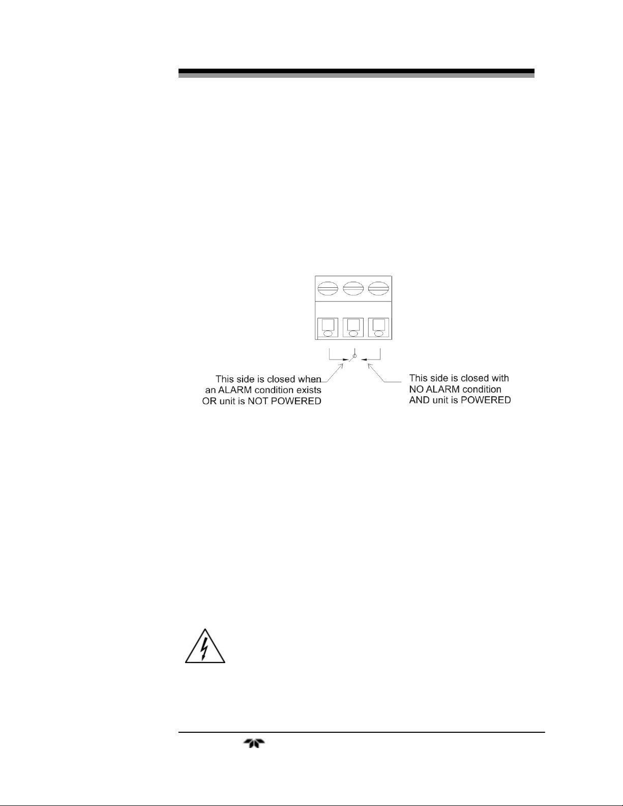
The alarm relay circuits are designed for failsafe operation,
meaning the relays are energized during normal operation. If power fails
the relays de-energize (alarms activated).
The contact connections are indicated diagrammatically on the rear
panel as Normally Closed, Common, and Normally Open. Figure 3-3
explains how these act in failsafe operation.
Alarm 1 and Alarm 2 are configured as HI and LO respectively. A
HI alarm will activate when concentration is above threshold, while a
LO alarm will activate when concentration is below threshold.
Figure 3-3: Contact ID for FAILSAFE Relay Operation
The specific descriptions for each type of alarm are as follows:
Alarm #1 Programmable as high alarm. Can be set anywhere
between 0 and 100 % but no lower than Alarm #2.
Alarm #2 Programmable as low alarm. Can be set anywhere
from 0 to 100 % but no higher than Alarm #1.
Sensor Fail Actuates when the output of the sensor falls below a
factory programmed acceptable level or the
thermocouple is open.
CAUTION: THERE COULD BE HAZARDOUS VOLTAGE AT THE
ALARMS TERMINALS, EVEN WHEN POWER IS
REMOVED FROM THE INSTRUMENT.
Teledyne Analytical Instruments 27
Page 28

Installation Model 9060L
3.4.1 Oxygen Probe Connections
The receptacle for the probe cable is located in the lower left-hand
corner of the rear panel. The 6-pin polarized connector is keyed to fit
only one way into the receptacle. Do not force it in. The other end of the
cable connects to the probe assembly. See Figure 3-5. Connect the probe
lead as shown in Figure 3-4 . The heater connector is on the right-hand
corner of the rear panel. Six foot long cables are provided for the
remote probe and the heater. Their Teledyne Analytical Instruments part
numbers are listed on the spare parts list located in the appendix.
Figure 3-4:Model 9060L Heated Probe Cable Connection
Teledyne Analytical Instruments 28
Page 29

Percent Oxygen Analyzer Installation
Figure 3-5: Connections to Probe
3.5 Installation Checklist
Prior to powering up the unit make sure you have:
Installed the unit correctly
•
Checked the probe and welded probe socket for leaks
•
Once the above checks have been made, you can connect the power
source. Wait approximately 30 minutes for warm up, two hours wait is
best. After that, the instrument is ready for operation.
Teledyne Analytical Instruments 29
Page 30

Installation Model 9060L
Teledyne Analytical Instruments 30
Page 31

Percent Oxygen Analyzer Operation
Operation
4.1 Introduction
Once the analyzer has been mounted, the probe installed, and the
electrical connections made, the analyzer can be configured for your
application. This involves setting the system parameters:
Defining the user selectable analysis ranges.
•
Setting alarm setpoints.
•
Calibrating the instrument.
•
All of these functions are performed via the front panel controls,
shown in Figure 4-1.
Analyzing for the percent oxygen level in the gas passing through
the probe and sensor is the default mode of operation. As long as no
front panel buttons are being pressed the analyzer is analyzing.
Figure 4-1: Front Panel Controls and Indicators
Teledyne Analytical Instruments 31
Page 32

Operation Model 9060L
4.2 Using the Function and Data Entry Buttons
When no buttons on the analyzer are being pressed, the instrument
is in the analyze mode. It is monitoring the percent of oxygen in the
sample gas that is flowing through the remote probe.
When one of the function buttons is being pressed, the analyzer
enters the setup mode or the calibration mode.
Setup Function Buttons:
There are 4 setup function buttons on the analyze:
SET ALARM 1
•
SET ALARM 2
•
SET HI RANGE
•
SET LO RANGE
•
Calibration Button:
The calibration mode button is:
SPAN
•
Data Entry buttons:
The data entry buttons (Δ and ∇) increment the values displayed on
the PERCENT OXYGEN meter while one of the function buttons is
being held down.
Δ : Increments the displayed value upwards.
•
∇ : Increments the displayed value downwards.
•
Any of the functions can be selected at any time by holding down
the appropriate button.
Each function will be described in the following sections. Although
the operator can use any function at any time, the order chosen in this
manual is appropriate for an initial setup.
4.3 Setting the Analysis Ranges
The two user definable analysis ranges are both capable of being
adjusted for from 0-1 to 0-100% oxygen concentration. Whatever values
are selected, the analyzer automatically switches from the LO range to
the HI range when the oxygen concentration reaches 100% of the LO
Teledyne Analytical Instruments 32
Page 33

Percent Oxygen Analyzer Operation
range full scale value, and it switches back to the LO range when the
oxygen concentration reaches 85% of the LO range full scale value
Note: The HI Range setpoint MUST be set at a higher
concentration percentage than the LO Range setpoint.
4.3.1 HI Range
Setting the HI Range full scale value defines the LEAST sensitive
analysis range to be used. To set the HI Range:
1. Press the SET HI RANGE function button once.
2. Immediately (within 5 seconds) press either the Δ or ∇ button
to raise or lower the displayed value, as required, until the
display reads the desired full scale percent concentration.
4.3.2 LO Range
Setting the LO Range full scale value defines the MOST sensitive
range to be used. To set the LO Range:
1. Press the SET LO RANGE function button once.
2. Immediately (within 5 seconds) press either the Δ or ∇ button
to raise or lower the displayed value, as required, until the
display reads the desired full scale percent concentration.
4.4 Setting the Alarm Setpoints
The alarm setpoints can be adjusted over the full range of the
analyzer (0-100% oxygen content). They are set as a percent of oxygen
content, so that an alarm set to indicate 9.6 on the display will activate at
9.6% O
4.4.1 Set Alarm 1 (HI alarm)
preferences:
on any O2 range.
2
Alarm 1 is preset as a high alarm. To configure this alarm to your
Press the SET ALARM 1 function button once.
1.
2.
To change the setting at which the alarm will be actuated, press
the SET ALARM 1 function button once more. The alarm
setpoint will flash on the LED display. Press either the Up or
Down keys to raise or lower the displayed value, as required,
Teledyne Analytical Instruments 33
Page 34

Operation Model 9060L
until the display reads the desired percent concentration. If
within 5 seconds no key is pressed, the instrument will return to
the sample mode and display oxygen concentration.
After setting the value wait for the unit to time out of this mode
(approximately 5 seconds) and return to displaying oxygen
concentration.
4.4.2 Set Alarm 2 (LO alarm )
Alarm 2 is preset as a low alarm. To configure this alarm to your
preferences:
1.
Press the SET ALARM 2 function button once.
2.
To change the setting at which the alarm will be actuated, press
the SET ALARM 2 function button once more. The alarm
setpoint will flash on the LED display. Press either the Up or
Down keys to raise or lower the displayed value, as required,
until the display reads the desired percent concentration. If
within 5 seconds no key is pressed, the instrument will return to
the sample mode and display oxygen concentration.
After setting the value wait for the unit to time out of this mode
(approximately 5 seconds) and return to displaying oxygen
concentration.
4.4.3 Sensor Fail Alarm
The SENSOR FAIL alarm is factory set to a reading less than
0.05% O
. Should this alarm trigger, the ALARM indicator below the
2
SET function buttons will blink, and the alarm relay contact dedicated to
this function will change state.
The SENSOR FAIL alarm will also activate when the temperature
is below 650°C, or the thermocouple is sensed as open.
4.5 Selecting a Fixed Range or Autoranging
The Model 9060L can operate in fixed high, fixed low, or
autoranging mode. To change modes:
1.
Press and then release the SET HI RANGE and the SET LO
RANGE buttons simultaneously.
Teledyne Analytical Instruments 34
Page 35
Percent Oxygen Analyzer Operation
2. Immediately (within 5 seconds) press either the Δ or ∇ button
until Auto, Lo, or Hi displays on the LCD, as desired.
After about three seconds, the analyzer resumes monitoring in the
selected range mode.
4.6 Oxygen Calibration
There are two types of calibration one is air calibration, and the
other is span which uses some other gas other than air. Since the zirconia
sensor uses air as reference, the output is nearly zero millivolts. So, in
doing the air calibration, you are basically reading the offset of the
sensor. The span calibration (using gas other than air) would make the
sensor give an output other than zero, thus it is the high calibration.
4.6.1 Span Calibration
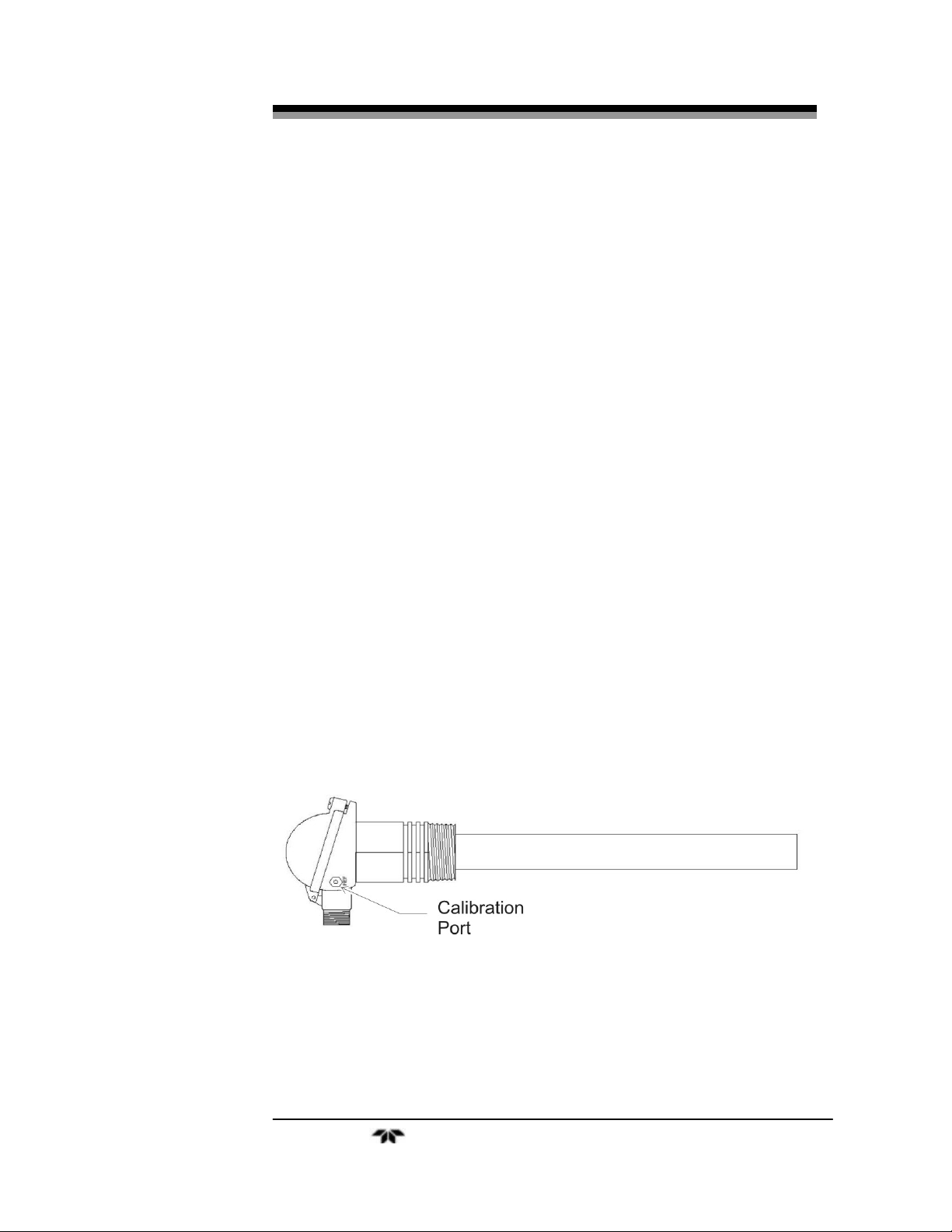
Connect a suitable span gas to the port on the side of the probe
head. To do this, remove the plug on the gland on the side of the probe
marked REF. See Figure 4.2 Attach the span gas at this port using a
suitable fitting and use a flow rate between 1-5 lilters per minute. The
span gas exits at the tip of the probe. A suitable span gas can be an
oxygen mixture between 1 to 16 %, with the balance being nitrogen.
Using a concentration between 1 to 5% is preferable, as the sensor will
yield a higher output.
Power up the instrument and allow the LED reading to stabilize.
Set the alarm setpoints and the full scale ranges to the desired values.
Figure 4-2: Calibration Port on Probe Head
Span Procedure:
1. Press the SPAN button once.
Note: The numeric LED starts flashing and will continue to flash
Teledyne Analytical Instruments 35
Page 36

Operation Model 9060L
for five minutes before timing-out. During this five minute
interval, the LED will continue to track gas through the
analyzer.
2. Flow span gas of a known oxygen concentration (between 1 and
16% oxygen) into the analyzer. The analyzer will begin to track
the span gas.
Note: The alarms will not change state during span calibration.
3. When the meter stabilizes, use the UP/DOWN arrows to adjust
the analyzer span value to the exact percent O
concentration in
2
the span gas. Remember that the acceptable range is 1 to 16% of
adjustment. The display will freeze at 1% or 16% if you try to
adjust beyond those limits.
Note: When an arrow button is first pressed, the LED begins
flashing slightly more rapidly and no longer tracks the span
gas. Instead, it responds to the UP/DOWN keystrokes.
Note: While the LED is flashing slightly more rapidly, the SPAN
routine will time-out in five seconds (instead of five
minutes), if no further keystrokes are entered.
4. When the span value is set to the known concentration of O
2
in
the span gas, stop pressing the keys and wait for five seconds.
Note: When you stop pressing the UP/DOWN keys, the rapid
flashing will cease and the analyzer will acquire the new
span value after five seconds.
The alarms will only be non-responsive for 60 seconds.
This time frame allows you to reintroduce sample gas into
the analyzer.
5. Shut off the span gas flow and immediately flow sample into the
analyzer.
After a few minutes, disconnect the calibration gas line and
6.
replace the plug to cap off the calibration port.
Teledyne Analytical Instruments 36
Page 37

Percent Oxygen Analyzer Operation
4.6.2 Air Calibration
To perform air calibration, make sure you have air flowing through the
same inlet you use for span calibration at a flow of 1- 5 liters per minute. Wait
for readings to stabilize.
Press both the SET ALARM 1 and SET ALARM 2 simultaneously. The
LED display will show “OFSt” for a few seconds. After that the instrument
should read near 20.9%.
The sensor output is expected to be near zero millivolts, if the offset of
the sensor is too high, the analyzer will not calibrate.
4.7 Supplementary Information
If, during the span procedure, you pressed the SPAN button by
mistake, you must wait five minutes for the analyzer to resume analysis
or you can press the UP button and then the DOWN button. (Pressing
the UP and DOWN buttons causes the analyzer to time-out in five
seconds instead of five minutes).
If during the span procedure, you press the RANGE or ALARM
buttons:
- either the range or alarm routine will be activated.
- any changes to span will be rejected.
- the 60 second alarm delay will not occur, i.e., the alarms
will be responsive immediately.
CAUTION: TI/AI CONSIDERS THE ACTION OF PRESSING THE
ALARM OR RANGE BUTTONS TO BE AT YOUR (THE
USER’S) DISCRETION AND NOT UNDER
GUARANTEE OF ALARM PROTECTION.
4.8 Probe Temperature
The probe temperature can be displayed momentarily and adjusted
if needed. While the instrument is in normal mode, displaying oxygen
concentration, press the UP and DOWN arrow keys simultaneously. The
red LED display will show the probe temperature in degrees centigrade
for five seconds.
Teledyne Analytical Instruments 37
Page 38
Operation Model 9060L
Within the time the temperature is being displayed, one can use the
UP and DOWN arrow keys to adjust the temperature, thus recalibrating
the temperature readout.
WARNING: TEMPERATURE READING IS CALIBRATED AT THE
FACTORY. DO NOT ATTEMPT RECALIBRATION OF
THE PROBE TEMPERATURE. ERROR OF A FEW
DEGREES WOULD HAVE LITTLE IMPACT ON THE
OXYGEN CALCULATIONS, BUT IF THE PROBE IS
GROSSLY MISCALIBRATED IT WILL HAVE AN
ADVERSE EFFECT ON THE OXYGEN READOUT.
ONLY QUALIFIED PERSONNEL SHOULD RECALIBRATE TEMPERATURE.
4.8.1 Low Temperature
For the zirconia sensor to operate properly the temperature of the
probe must be above 650 degrees Centigrade. While the temperature is
below this threshold, the red LED alternates showing
“t-Lo” and the
oxygen concentration.
4.8.2 Open Thermocouple
The electronics checks if the thermocouple (TC) is open. If it
detects that the TC is open the Sensor failure contacts will go into
alarming position. Red LED display may alternate between oxygen
concentration and the error code
“-02-”. Refer to Section 4.9 for
information on Error Codes.
4.9 Error Messages
The instrument will display an error code when it detects a
malfunction or error condition. The possible codes and common causes
are listed below:
-01- This message indicates that there is possible failure on the
Analog to Digital Converter, ADC. This may happen when the
micro-controller cannot communicate with the ADC. In this
state, the oxygen reading is unreliable.
-02- This message is displayed when the input voltage to the ADC
rises above the upper limit of the ADC. This could occur if the
probe is exposed to zero oxygen concentration, making the
Teledyne Analytical Instruments 38
Page 39

Percent Oxygen Analyzer Operation
output of the sensor higher than the top scale of the ADC. It may
also occur if the thermocouple should open.
-03- This message is displayed when the input voltage to the ADC
has fallen below the lower negative limit of the ADC.
Teledyne Analytical Instruments 39
Page 40

Operation Model 9060L
Teledyne Analytical Instruments 40
Page 41

Percent Oxygen Analyzer Maintenance
Maintenance
Aside from normal cleaning and checking for leaks at the probe
connection, the Model 9060L should not require any maintenance
beyond replacement of a blown fuse. Routine maintenance includes
occasional recalibration, as described in Chapter 4,
5.1 Replacing the Fuse
CAUTION: REMOVE POWER TO UNIT BEFORE REPLACING
THE FUSE.
Operation.
When a fuse blows, check first to determine the cause, then replace
the fuse using the following procedure:
1.
Disconnect the AC power and place the power switch located on
the rear panel in the
receptacle.
The fuse receptacle is located in the power cord receptacle
2.
assembly in the upper left-hand corner of the rear panel. See
Figure 5-1.
O position. Remove the power cord from the
Figure 5-1: AC Fuse Replacement
Teledyne Analytical Instruments 41
Page 42

Maintenance Model 9060L
3. Insert a small flat-blade screwdriver into the slot in the receptacle
wall nearest the fuse and gently pry open the fuse receptacle. The
fuse holder will slide out. There are two fuses in use and are
visible in the clip.
Remove the bad fuse and replace it with a 5x20mm 2A,
4.
250 VAC, IEC time lag (T) fuse (P /N F1296).
Replace the fuse holder into its receptacle, pushing in firmly
5.
until it clicks.
Teledyne Analytical Instruments 42
Page 43

Percent Oxygen Analyzer Appendix
Appendix
A.1 Specifications
Ranges: 0-3 % and 0-10 % oxygen (Standard
Ranges), and 0-25 % (nominal)
Calibration Range. User selectable %
Ranges can be set between 1% and 100 %
oxygen .
Signal Output: Voltage: 0–10 VDC, negative ground
Current: 4-20 mA, negative ground
Display: Light emitting diode display.
Alarms: Two customer selectable fully adjustable
One sensor failure alarm.
Alarm relays form "C" contacts, dry
System Operating Temp: 0-50 °C
Accuracy
Response Time: 90% in less than 4 seconds at 25 °C.
System Power Requirements: 120 VAC, 50/60Hz (optional 220VAC),
Range ID: 0-10 VDC.
HI and LO alarms.
contacts rated at 2A for 30VDC, 1A for
115VAC.
: ±2% of full scale at constant temperature
±5% of full scale through operating temp.
range once temp. equilibrium is reached.
(At 3 % and higher user defined ranges.)
110W.
System Enclosure: Panel mount. Dimensions (Approx.) 7.0
W x 6.75 H x 4.26 D.
Teledyne Analytical Instruments 43
Sensor Type: Zirconia, solid state
Page 44

Appendix Model 9060L
A.2 Probe Specifications
Application: Combustion flue below 700°C (1290°F),
above 700°C (1290°F) 900°C (1650°F) — no
contaminants.
With contaminants see notes 1 &2
Temperature Range: 0-900°C 800-1400°C 800-1200°C
(32-1650°F) (1470-2550°F) (1470-2190°F)
Length: 250-1000 mm 500-1160 mm 457-1219 mm
(10” to 40”) (20” to 46”) (18” to 48”)
Process Connection: 1 1/2" BSP 3/4" BSP 1" BSP or equivalent
NPT
Electrical Connection: Weatherproof plug-in connector or
optional screw terminals. Plug connector
supplied with the cable. Ex d heads have
screw terminals.
Cable: Order a specific length with the analyzer
except for hazardous installations where
the cable is supplied by the customer.
Heater: Yes
Flue Gas Thermocouple: K
Response Time: Typically < 4 secs.
Reference Gas: Ambient air 50 to 500 cc/min (6 to 60
Head Temperature: 125°C (250°F)
scfm). Pump supplied with analyzer
Ref Air Connection: 1/4" NPT integral air line in probe cable.
Barbed fitting to 3/16" ID PVC tube.
Filter: Removable sintered stainless steel
particulate filter, 15 micron.
Calibration Gas Connection: 1/8" NPT female 1/8" NPT female 1/8"
NPT female
Weight : 0.6 kg (1.32 lbs.)
Teledyne Analytical Instruments 44
Page 45

Percent Oxygen Analyzer Appendix
Notes:
1. Care must be taken to avoid contact with explosive or
inflammable gases with 9060L heated probes when hot.
Please contact factory for corrosives other than sulphur or zinc.
2.
We can provide test materials to try in your atmosphere.
A.3 Spare Parts List
QTY. P/N DESCRIPTION
1 B-76751A PC Board, Main
1 B-76513A PC Board, Power Supply
2 F-1296 Fuse (AC), 2A, 250VAC, IEC Type T,
5x20mm
1 --- Oxygen Probe (call TI/AI to specify U
Length)
1 B77926A Cable Assembly, Probe Heater
1 B77926B Cable Assembly, Remote Probe
Note :Orders for replacement parts should include the part
number and the model and serial number of the system for
which the parts are intended.
Send orders to:
TELEDYNE INSTRUMENTS
Analytical Instruments
16830 Chestnut Street
City of Industry, CA 91749-1580
Telephone: (626) 934-1500
Fax: (626) 961-2538
Web: www.teledyne-ai.com
or your local representative.
Email: ask_tai@teledyne.com
Teledyne Analytical Instruments 45
Page 46

Appendix Model 9060L
A.4 Reference Drawing
D-77712 Outline Diagram
D77713 Control Unit Final Assembly
C77925 Interconnection Diagram
A.5 Probe or Sensor EMF Tables
ZIRCONIA OXYGEN SENSOR OUTPUT (mV)
PROBE TYPE 9060L, SENSOR TYPE 9060LEX
% OXYGEN mV at 720°C (1320°F)
21.0 0.00
20.5 0.46
20.0 0.99
19.5 1.53
19.0 2.09
18.5 2.66
18.0 3.25
17.5 3.85
17.0 4.47
16.5 5.11
16.0 5.77
15.5 6.45
15.0 7.15
14.5 7.87
14.0 8.62
13.5 9.40
13.0 10.21
12.5 11.05
12.0 11.92
11.5 12.83
Teledyne Analytical Instruments 46
Page 47

Percent Oxygen Analyzer Appendix
11.0 13.78
10.5 14.78
10.0 15.82
9.5 16.92
9.0 18.08
8.5 19.30
8.0 20.60
7.5 21.98
7.0 23.45
6.5 25.04
6.0 26.75
5.5 28.61
5.0 30.65
4.5 32.90
4.0 35.42
3.5 38.28
3.0 41.58
2.5 45.48
2.0 50.25
1.5 56.41
1.0 65.08
0.5 79.91
0.2 99.51
'K’ TC mV 29.212 at 720 °C (1320°F)
These tables are based on the Nernst equation:
Sensor e.m.f. = 0.02154 x T x 1n ( 20.95 / % oxygen),
where T = ° K (° C + 273), e.m.f. is in mV’s
Teledyne Analytical Instruments 47
Page 48

Appendix Model 9060L
Teledyne Analytical Instruments 48
Page 49

Percent Oxygen Analyzer Index
Index
accuracy, 43
address, 45
air calibration, 35, 37
air purge, 16
alaram delay, 36
alarm, 43
concentration, 12
HI, 27
LO, 27
sensor fail, 27, 34
sensor failure, 12
setpoint, 33
threshold, 12, 27
Alarm 1, 27
Alarm 2, 27
alarm connection, 26
alarm connections, 14
alarm delay, 37
alarm indicator, 12
alarm relay circuit, 27
alarm setpoint, 13
analog concentration signal, 22
analog to digital converter, 20, 21, 38
analysis range, 32
analyze mode, 32
applications, 11
autoranging, 11
block diagram, 21
BSP socket, 23
cable, 44
calibration, 35
calibration check, 16
calibration mode, 32
calibration mode keys, 32
calibration range, 11
caution sign, iv
CMOS, 11
combustible gas warning, x
concentration output. See output
contact ID, 27
contaminants, 15
control unit, 15, 16
copyright, ii
current to voltage converter, 22
data entry keys, 13, 32
default mode, 31
digital concentration signal, 22
digital meter. See display
digital to analog converter, 20, 22
dimensions, 43
display, 11, 13, 43
display control, 20
display, frozen, 36
Down Arrow, 13
E–I converter, 22
EMF table, 46
error code, 38
failsafe, 27
features, 11
figures listing, viii
filter, 17, 24, 44
flow guide tube. See guide tube
flow rate, 37
flow rate, span gas, 35
flue velocity, 17
form "C" contacts, 43
Form C relay contacts, 26
front panel, 12, 31
function keys, 12
fuse, 25, 42
fuse block, 25
fuse replacement, 41
gas connection, 44
general purpose area, 23
guide tube, 17, 24
heated probe, 16
heater, 19
heater control, 18
heater power, 20
HI range, 32
impedance, 20
impedance alarm, 20
increment the display, 32
initial setup, 32
Teledyne Analytical Instruments 49
Page 50

Index Model 9060L
input connector, 13
insertion length, 17
instasllation checklist, 29
instrument range, 11
internal power switch, 20, 25
lagging extension, 17
leak check, 29
LED, 13
LED flashing, 35
LO range, 33
main PCB, 21
maintenance, 41
manuals, additional, v
Measurement Parameters Readout, 13
membrane switches, 12
Meter Readout, 13
micro-controller, 15, 20, 21
millivolt potential, 21
mounting thread, 17
Nernst equation, 19, 47
NPT socket, 23
OFSt, 37
open thermocouple, 27, 34, 38
operating temperature, 43
operation, 31
output, 15, 43
analog, 12, 14
current, 26
range ID, 26
voltage, 26
output connector, 13
oxygen partial pressure, 19
oxygen reading reliability, 20
oxygen reading unreliable, 38
panel mount, 23
parts list, 45
power, 20
power connection, 14
power cord, 25
power cord receptacle, 25, 41
power requirements, 43
power supply PCB, 20
power switch, 14, 25
pressure, 18
pressure compensation, 20
probe, 15, 16, 18, 20
probe cable connection, 28
probe configuration, 17
probe installation, 23
probe length, 17, 44
probe mounting angle, 24
probe options, 17
probe temperature, 13, 21, 37
process pressure. See pressure
pump, 18, 44
RAM, 11, 20
range, 13, 43
range ID, 22, 43
range identification, 12
range switch-over point, 33
rear panel, 13, 14, 25
REF, 35
reference air, 16
reference air pump, 18
reference gas, 44
relay, 18, 22, 43
relay contacts, 26
response time, 15, 24, 43, 44
ROM, 11, 20
safety information, iv
sampling line, 18
sensor, 11, 15, 16, 18, 20
sensor amplifier, 20, 21
sensor connector, 14
sensor offset, 35
sensor temperature, 19
serial number, iii
Set Alarm 1, 12
SET ALARM 1, 32, 33
Set Alarm 2, 13
SET ALARM 2, 32, 34
Set HI Range, 13
SET HI RANGE, 32, 33
Set LO Range, 13
SET LO RANGE, 32, 33
setup function keys, 32
setup mode, 32
sheath, 16
signal processing, 15, 20
solenoid, 16
solid electrolyte, 18
Span, 13
SPAN, 32, 35
span calibration. See calibration
span calibration point, 13
span gas, 35
span gas concentration, 35
span value acquisition time, 36
stratification, 25
system parameters, 31
Teledyne Analytical Instruments 50
Page 51

Percent Oxygen Analyzer Index
tables listing, ix
technician symbol, iv
temperature, 44
temperature controller, 18
temperature maximum, 24
temperature too low, 38
thermal shock, 15, 24
thermocouple, 18
thermocouple type, 44
time out, 34
time-out, 37
t-Lo, 38
transit time, 24
U length, 24
Up Arrow, 13
voltage amplifier, 21
warning sign, iv
warranty, ii
water vapor, 16
website address, v
zero oxygen concentration, 38
zirconia element, 18
zirconia sensor. See sensor
Teledyne Analytical Instruments 51
 Loading...