

Teledyne LeCroy WaveStation 3000, LeCroy WaveStation 3082, LeCroy WaveStation 3122, LeCroy WaveStation 3162 Operator's Manual
Operator's
Manual
WaveStation 3000
Function & Arbitrary
Waveform Generator

WaveStation 3000 Function and Arbitrary Waveform Generator Operator's Manual
© 2013 Teledyne LeCroy, Inc. All rights reserved.
Unauthorized duplication of Teledyne LeCroy documentation materials other than for internal sales and
distribution purposes is strictly prohibited. However, clients are encouraged to distribute and duplicate
Teledyne LeCroy documentation for their own internal educational purposes.
WaveStation and Teledyne LeCroy are trademarks of Teledyne LeCroy, Inc. Other product or brand names are
trademarks or requested trademarks of their respective holders. Information in this publication supersedes
all earlier versions. Specifications are subject to change without notice.
922869 Rev B
November 2013

Operator's Manual
Contents
Welcome iii
Introduction to WaveStation 1
Package Contents 2
Front Panel 3
Back Panel 4
Adjusting the Viewing Position 4
Safety 5
Working with WaveStation 7
Function Buttons 7
Understanding the Display 8
Navigating Menus and Making Selections 8
Adjusting Parameters 10
Using WaveStation Help 11
Generating Basic Waveforms 12
Generating a DC Waveform 14
Generating an Arbitrary Waveform 15
Generating Modulated Waveforms 16
Generating an AM Modulated Waveform 16
Generating an FM Modulated Waveform 17
Generating a PM Modulated Waveform 17
Generating an FSK Modulated Waveform 18
Generating an ASK Modulated Waveform 18
Generating a DSB-AM Modulated Waveform 19
Generating a PWM Modulated Waveform 19
Generating Sweep Waveforms 20
Generating Burst Waveforms 21
N-Cycle Burst 21
Gated Burst 22
Using External Trigger 23
Using Sync Out 24
Save/Recall 25
Save/Recall Setups 26
Save/Recall Waveforms 27
Delete Setup or Waveform File 27
Copy Channel Settings 27
Changing System Settings 28
Output 28
USB Output 28
Number Format 28
Power On Setting 29
Sound 29
Screen Saver 29
922869 Rev B
i

WaveStation 3000 Function and Arbitrary Waveform Generator
Clock Source 29
Restoring the Default Settings 30
Remote Control of WaveStation 31
GPIB Remote Control 31
USBTMC Remote Control 32
Using LabView Software 32
Using WaveStation PC Software 33
Installing WaveStation PC Drivers and Software 33
Connecting WaveStation to the PC 34
Reading Files from WaveStation on a PC 34
Sending Waveform Files from a PC to WaveStation 37
Save Waveform to .CSV File 40
Maintaining WaveStation 41
Cleaning 41
Updating WaveStation Firmware 41
Self Tests 42
Self Calibration 43
Returning a Product for Service 44
Reference 45
Specifications 45
Certifications 45
Warranty 48
Contact Teledyne LeCroy 49
Index 50
ii
922869 Rev B

Operator's Manual
Welcome
Thank you for purchasing a LeCroy WaveStation 3000 Series Function and Arbitrary Waveform Generator.
We’re certain you’ll be pleased with the detailed features so unique to our instruments.
This manual documents how to use the following WaveStation models:
l WaveStation 3082 80 MHz
l WaveStation 3122 120 MHz
l WaveStation 3162 160 MHz
The manual contains sections addressing:
l Product overview and safety information
l Working with WaveStation
l Generating basic, arbitrary, modulated, sweep, and burst waveforms
l Remote control
l Using WaveStation PC Software
l Changing system settings and other maintenance
l Reference, including product certifications and Teledyne LeCroy contact information
WaveStation can be controlled remotely by an automation device or by a person using the WaveStation PC
Software. The information in this manual is supplemented by a SCPI (Standard Commands for Programmable
Instruments) Command Reference Manual available at teledynelecroy.com.
Additional supplemental information in the form of Application Notes and LabBriefs are also available from our
website.
We truly hope you enjoy using Teledyne LeCroy's fine products.
Sincerely,
David C. Graef
Teledyne LeCroy
Vice President and Chief Technology Officer
922869 Rev B
iii

WaveStation 3000 Function and Arbitrary Waveform Generator
iv
922869 Rev B

Operator's Manual
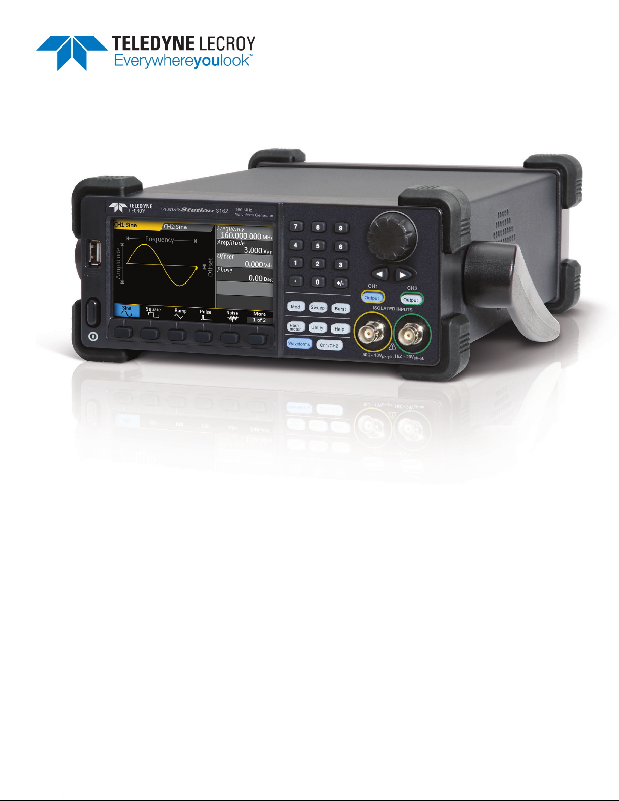
Introduction to WaveStation
With five basic signal types and over 30 built-in arbitrary waveforms, the WaveStation is a versatile waveform
generator. A variety of modulation schemes, large color display, simple user interface, and remote control
capabilities make it easy to generate waveforms up to160 MHz.
High Performance and Signal Fidelity
High performance hardware enables WaveStation to create accurate, stable waveforms. High sample rate and
resolution combined with low jitter and harmonic distortion means the waveforms seen on the display match
the waveforms output by the hardware.
Graphical Waveform Creation
Use WaveStation PC Software to easily create and edit waveforms on your computer using mathematical
operations, filters and point-by-point editing—or draw a waveform with a mouse. Transfer waveforms from the
PC to WaveStation over USB, then view them on the large display. Connect a WaveAce® oscilloscope to the
same PC to enable seamless transfer of captured signals from the oscilloscope to the WaveStation.
Key Specifications
Bandwidth 80 MHz – 160 MHz
Channels
Memory 512 kpts
Sample Rate 500 MS/s
Vertical Resolution 14 bits
2
Detailed specifications are maintained on the product page at:
teledynelecroy.com/wavestation.
922869 Rev B
1

WaveStation 3000 Function and Arbitrary Waveform Generator
Package Contents
When your WaveStation is delivered, verify that all items on the packing list or invoice copy have shipped
correctly. Contact your nearest Teledyne LeCroy customer service center or national distributor if anything is
missing or damaged. We can only be responsible for replacement if you contact us immediately.
The standard WaveStation 3000 package includes the following:
l WaveStation unit
l Power Cord
l Standard USB 2.0 Type A to Type B Cable, 1 m
l USB-GPIB Converter Cable
l WaveStation 3000 Getting Started Guide
l Performance/Calibration Certificate
l Product Registration Card
2
922869 Rev B
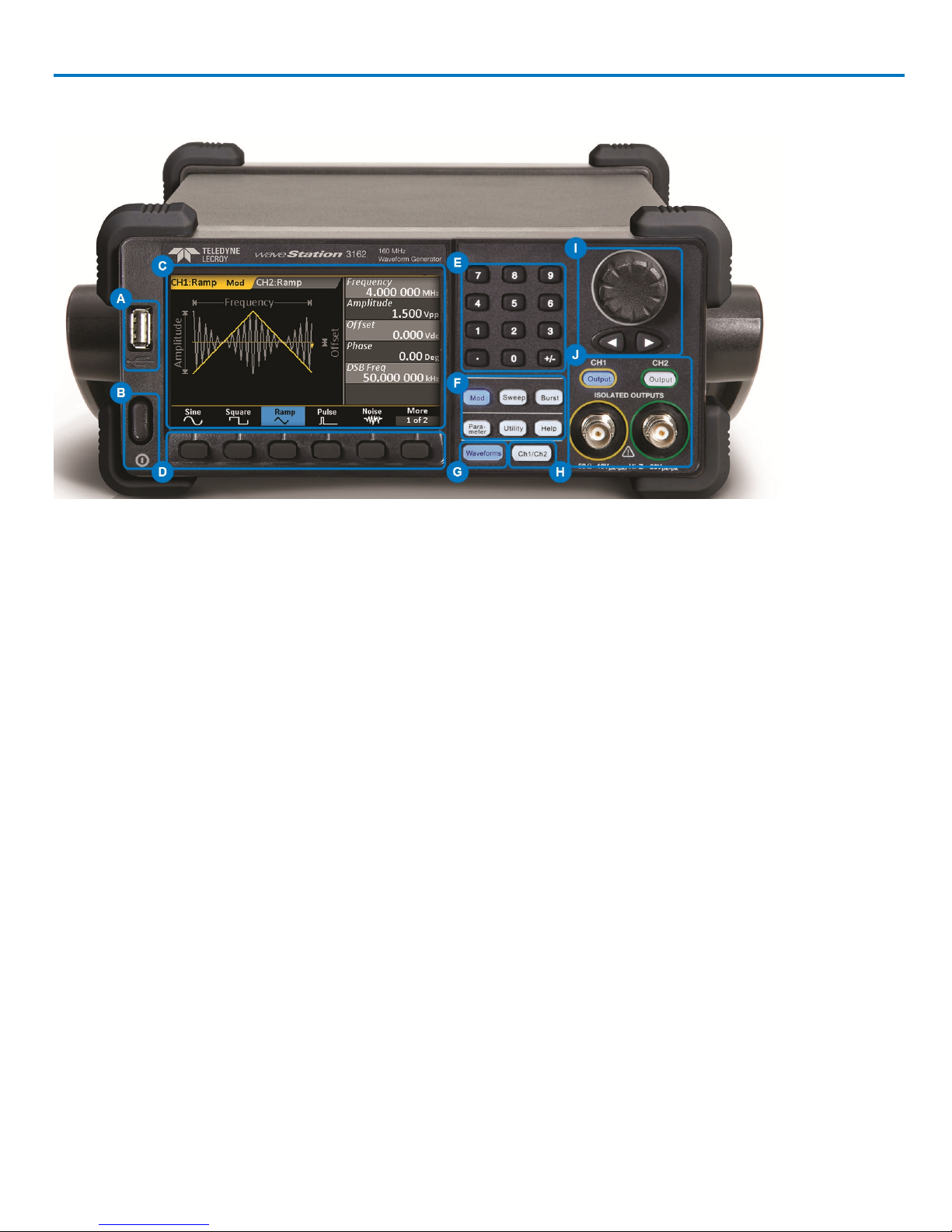
Front Panel
Operator's Manual
A. USB A Connector enables you to attach a storage drive.
B. Power Button turns on/off the WaveStation.
C. LCD Display shows an annotated waveform shape, the Parameter Value List, and the various option
menus.
D. Softkey Buttons enable you to select the corresponding option from the changing menus.
E. Numeric Keypad allows you to adjust parameter values and change units.
F. Function Buttons open corresponding option menus. The top, three Signal Conditioning buttons apply
Modulation, Sweep, or Burst to the active waveform. Parameter, Utility, and Help open their respective
menus.
G. Waveform Button opens the menu of waveform shapes.
H. Ch1/Ch2 Button selects the output channel and activates the corresponding tab on the display.
I. Adjustment Knob and Left/Right Cursor Buttonshelp with making selections and modifying values.
J. Output Buttons control the activation/deactivation of corresponding BNC Channel Outputs.
922869 Rev B
3
WaveStation 3000 Function and Arbitrary Waveform Generator
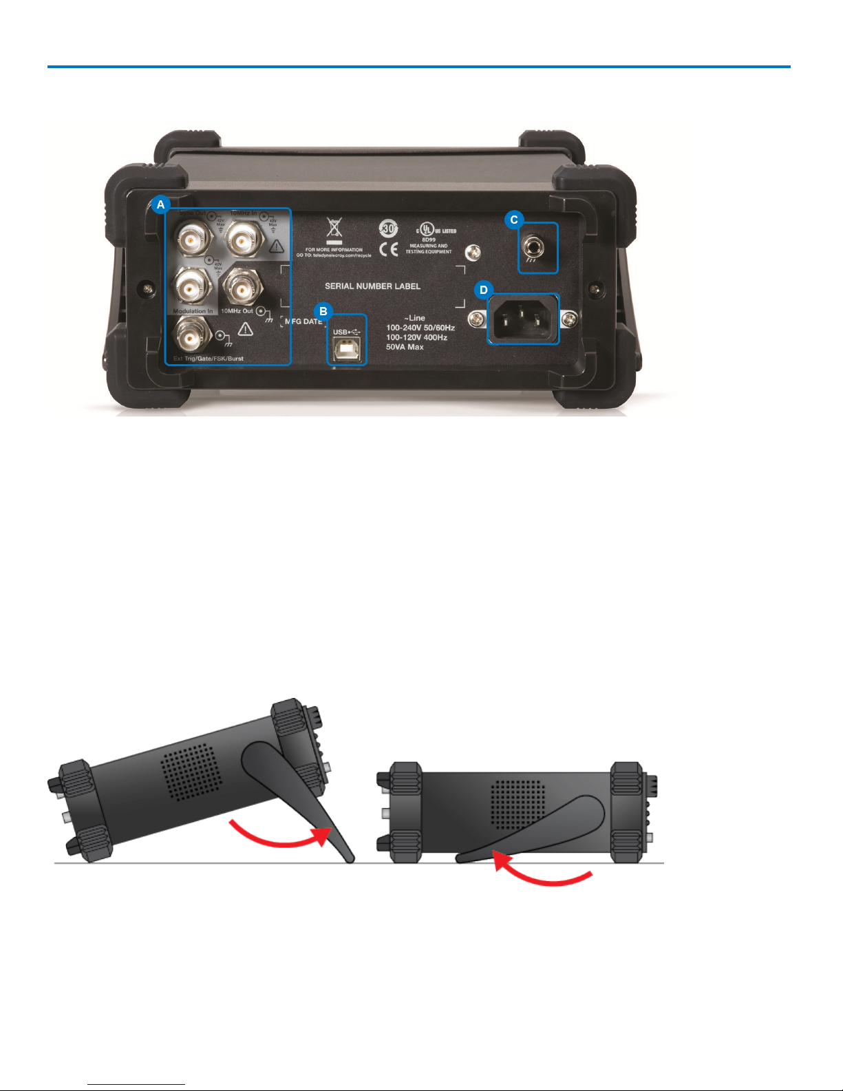
Back Panel
A. Input and Output BNC Connectors - provide 10 MHz In, 10 MHz Out,Modulation In, Synch Out, Ext
Trig/Gate/Fsk/Burst Out.
B. USB Connector - USB 2.0 Type B, used for making USBRAW or USBTMC connections.
C. Ground Connector
D. AC Power Connector
Adjusting the Viewing Position
The built-in carrying handle can be used to support the weight of the product and adjust the viewing position.
Gently pull both arms away from the sides of the WaveStation to unlock the mechanism, then rotate the
entire handle toward you until it snaps into the upright position.
4
922869 Rev B

Operator's Manual
Safety
Observe these instructions to keep the oscilloscope operating in a correct and safe condition. You are
required to follow generally accepted safety procedures in addition to the precautions listed here. The overall
safety of any system incorporating this instrument is the responsibility of the assembler of the system.
Symbols
These symbols may appear on the instrument's front or rear panels and in its documentation to alert you to
important safety considerations.
CAUTION of potential damage to instrument, or WARNING of potential bodily injury. Do not proceed until the information
is fully understood and conditions are met.
High voltage. Risk of electric shock or burn.
Measurement ground connection.
Safety (protective) ground connection.
Frame or chassis connection.
Power On/Off (front of instrument)
Precautions
Use proper power cord. Use only the power cord shipped with this instrument and certified for the country of
use.
Maintain ground. This product is grounded through the power cord grounding conductor. To avoid electric
shock, connect only to a grounded mating outlet.
Connect and disconnect properly. Do not connect/disconnect probes or test leads while they are connected to
a voltage source.
Observe all terminal ratings. Do not apply a voltage to any input (C1, C2, C3, C4 or EXT) that exceeds the
maximum rating of that input. Refer to the front of the oscilloscope for maximum input ratings.
Use only within operational environment listed. Do not use in wet or explosive atmospheres.
Use indoors only.
Keep product surfaces clean and dry. See Cleaning in the Maintenance section.
Do not block the cooling vents. Leave a minimum six-inch (15 cm) gap between the instrument and the
nearest object. Keep the underside clear of papers and other objects.
Do not remove the covers or inside parts. Refer all maintenance to qualified service personnel.
Do not operate with suspected failures. Do not use the product if any part is damaged. Obviously incorrect
measurement behaviors (such as failure to calibrate) might indicate impairment due to hazardous live
electrical quantities. Cease operation immediately and sequester the instrument from inadvertent use.
Operating Environment
Temperature: 0 to 40° C.
922869 Rev B
5

WaveStation 3000 Function and Arbitrary Waveform Generator
Humidity: Maximum relative humidity 80% for temperatures up to 31° C, decreasing linearly to 50% relative
humidity at 40° C.
Altitude: Up to 3,048 m (10,000 ft) at or below 30° C.
Cooling
The analyzer relies on forced air cooling with internal fans and vents. Take care to avoid restricting the
airflow to any part. Around the sides and rear, leave a minimum of 15 cm (6 inches) between the instruments
and the nearest object.The feet provide adequate bottom clearance.
CAUTION.Do not block cooling vents. Always keep the area beneath the instruments clear of paper
and other items.
The instruments also have internal fan control circuitry that regulates the fan speed based on the ambient
temperature. This is performed automatically after start-up.
Calibration
The recommended factory calibration interval is one year. Calibration should be performed by qualified
personnel only.
Extended warranty, calibration, and upgrade plans are available for purchase. To purchase a service plan,
contact your Teledyne LeCroy sales representative or:
cutomersupport@teledynelecroy.com
Power
AC POWER
The instrument operates from a single-phase, 100 to 240 Vrms (± 10%) AC power source at 50/60 Hz (± 10%)
and 100 to 120 Vrms (± 10%) AC power source at 400 Hz (± 5%). Manual voltage selection is not required
because the instrument automatically adapts to the line voltage.
POWER CONSUMPTION
50 VA (50 W) maximum power consumption when operating with all accessories installed.
GROUND
The AC inlet ground is connected directly to the frame of the instrument. For adequate protection again
electric shock, connect to a mating outlet with a safety ground contact.
WARNING. Only use the power cord provided with your instrument. Interrupting the protective
conductor inside or outside the oscilloscope, or disconnecting the safety ground terminal, creates a
hazardous situation. Intentional interruption is prohibited.
APPLYING POWER
The Power button on the front of the WaveStation controls the operational state of the instrument. Press the
button to switch the instrument AC power On or Off. Always use the Power button to execute a proper shut
down process and preserve settings before powering down. Do not power off by pulling the power cord from
the socket or shutting down a connected power strip.
6
922869 Rev B

Operator's Manual
Working with WaveStation
Function Buttons
These Front Panel buttons control major functional areas of the software.
They appear white when inactive, unlike the navigation and selection
controls, which are black.
Function buttons are lit blue when they are active. You can perform a Self
Test to check that the LED is working properly.
Channel and Waveform Buttons
The Ch1/Ch2 button is the starting point in waveform configuration. Press it to select the output channel and
activate the corresponding tab on the display.
The Waveform button opens the menu of basic and arbitrary waveform shapes. Whatever you select is
immediately assigned to the active channel.
Signal Conditioning Buttons
The top three function buttons are waveform signal conditioning buttons and apply Modulation, Sweep, or
Burst functions to the active waveform.
The first press of a Signal Conditioning button applies that functionality to the active waveform and opens a
menu of corresponding parameters. You'll see the name (e.g., "Mod" for Modulation) appear next to the carrier
waveform on the Channel tab. The second press removes the functionality from the waveform and closes the
menu.
Other Function Buttons
The next three function buttons, Parameter, Utility, and Help, open menus of functionality other than waveform
configuration.
l Parameter restores the menu of waveform parameters to the display for quick re-adjusting. This can be
useful if you've moved onto one of the other functional menus.
l Many output and system settings can be made through Utilities; see the topics in that section of this
manual.
l Help opens a menu of Help topics.
Output Buttons
These buttons, both labeled Output, each correspond to one of the output channels. They enable and disable
output on that channel. Connect a BNC cable to the output before activating the button.
922869 Rev B
7
WaveStation 3000 Function and Arbitrary Waveform Generator
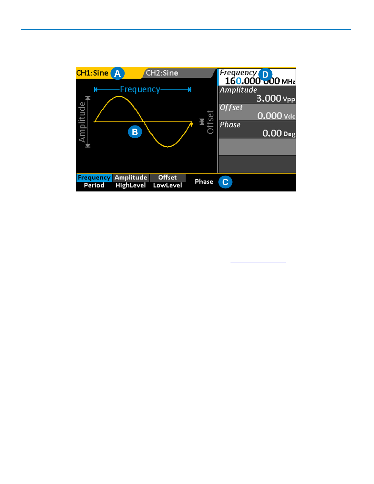
Understanding the Display
Each area of the display serves a unique function.
A. Channel Tabs display the currently selected waveform, plus any additional signal conditioning, such as
Modulation. The tab changes to match the channel color when it is active.
B. Waveform Display shows an annotated diagram of the waveform. The diagram shows how the selected
parameters relate to the wave shape.
C. Option Menu changes based on the chosen Waveform and Function.
D. Parameter Value List shows parameter settings. Use this area to adjust parameters.
Navigating Menus and Making Selections
Pressing any Function button opens a corresponding menu of options on the display. These menus are
navigated using the softkey buttons below them.
Option Menus and Softkey Buttons
The softkey buttons correlate with the menu options directly above them, which change based on
functionality. The softkeys behave a bit differently depending on the option. They may:
l Select a numeric parameter for editing on the Parameter Value List
l Toggle a set of non-numeric selections
l Open a second menu, etc.
Continue pressing the softkey button until your desired selection is highlighted in blue. Then, either adjust
the value on the Parameter List, or press the softkey for the next menu option you wish to select.
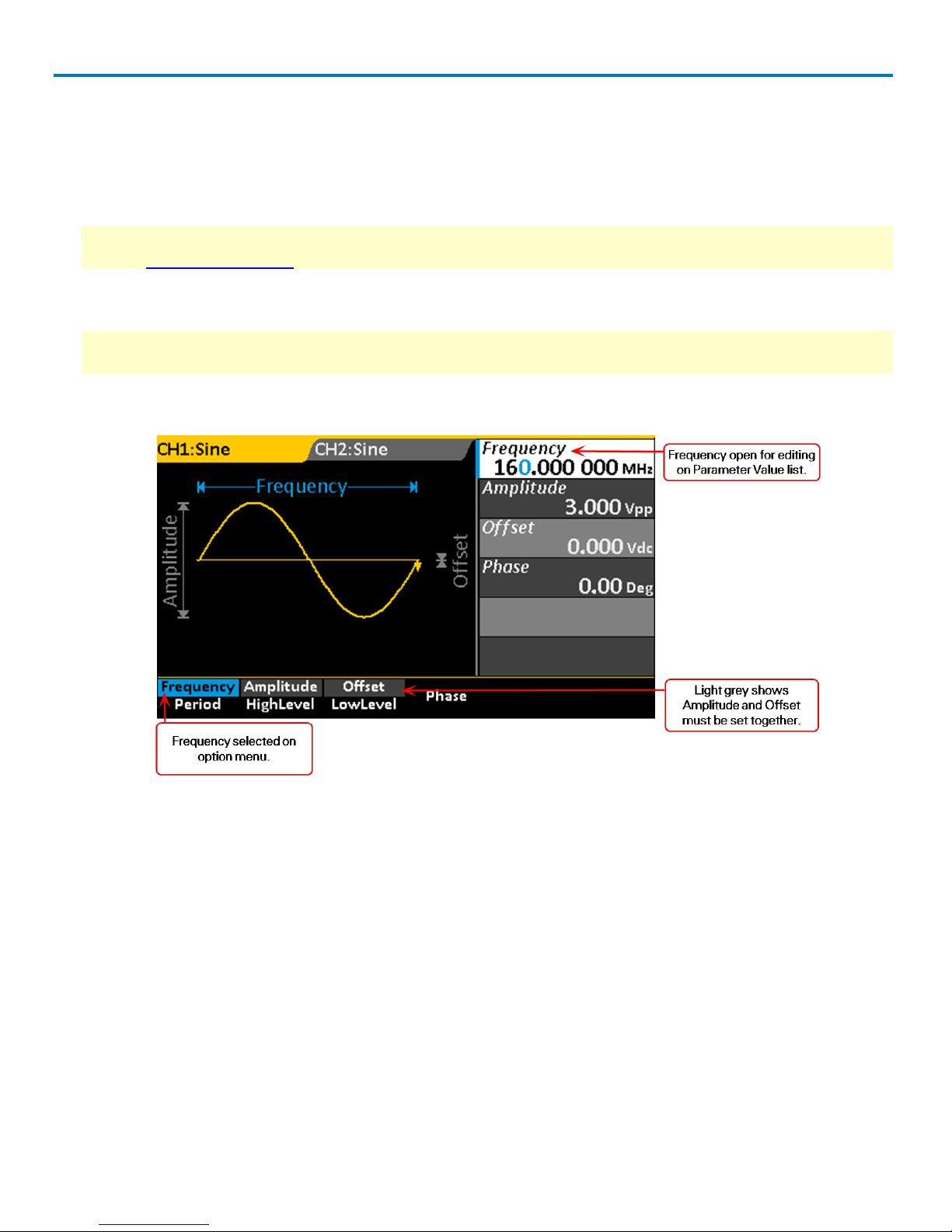
DUAL PARAMETER OPTIONS
A good portion of the menu options show two separate parameters.This indicates an either/or selection: you
can choose to configure one parameter or the other, but not both. For example, you can configure either
8
922869 Rev B
Operator's Manual
Frequency or Period, but not both.The first press of the softkey button selects the top parameter, which is then
highlighted in blue; the second press selects the bottom.
These dual parameter options have two different colored backgrounds, one lighter and one darker, to keep
them distinct. Selected parameters will show the lighter shading (when they are not active and blue), and
you'll notice that these are the parameters you see in the Parameter Value List. You may sometimes notice
that when you select one dual parameter, the shading changes over other dual parameters. This indicates
parameters that must be configured together. For example, Amplitude and Offset, or HighLevel and LowLevel.
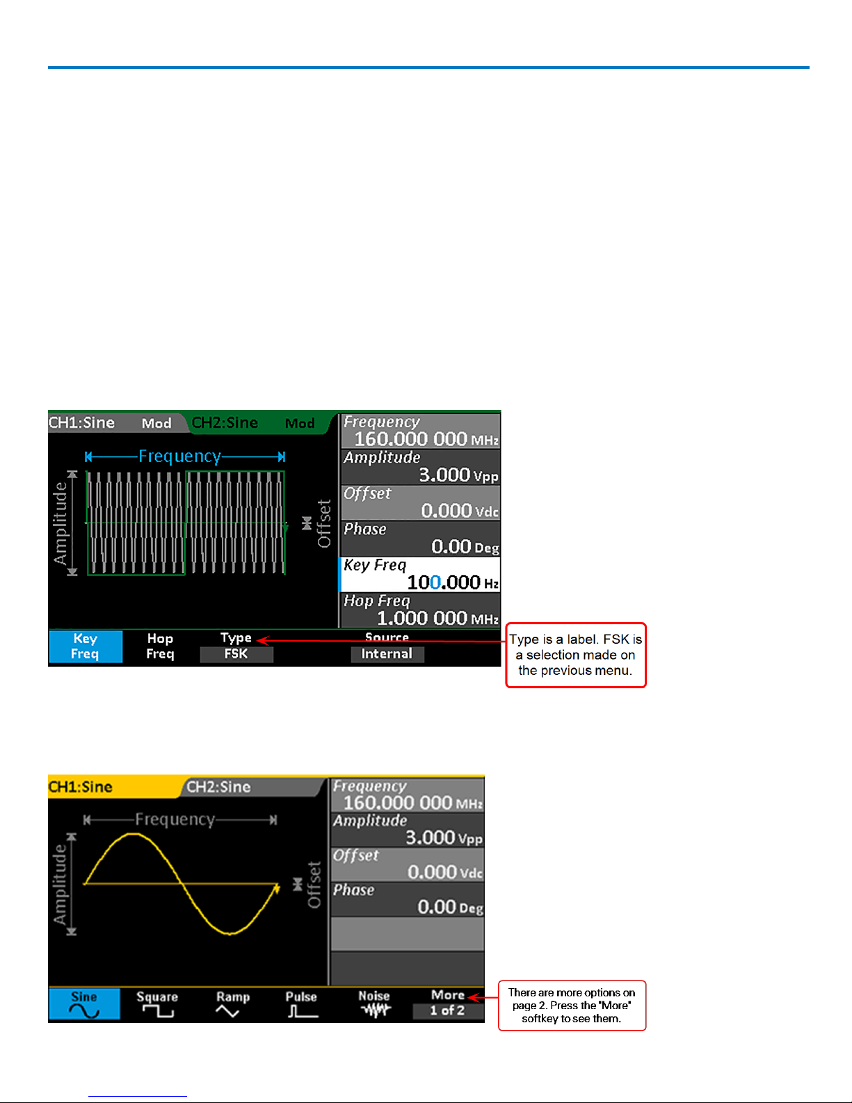
LABELED MENU OPTIONS
Some menu options appear to be dual parameters, but actually the top part of the option is a label, while the
bottom shows the selected value. When configuring waveforms, this usually indicates the selection was made
on a previous menu, but is made available again in case you decide to change it. For example, when you
display Modulation parameters, the Type option shows the selection made on the previous Modulation type
menu. You need only press the softkey for these menu options if you now wish to change the selection.
ADDITIONAL MENUS
Menus that have a More at the end have additional pages of options. Press the softkey button to go to the next
or previous page.
922869 Rev B
9

WaveStation 3000 Function and Arbitrary Waveform Generator
DONE AND CANCEL
Some option menus, such as Utilities, go several levels deep. In this case, you may see a Done or Cancel
option at the end of the menu. The procedures in this manual explain their use in specific situations, which
may vary slightly menu to menu.
Parameter Value List
The right side of the display is a detailed list of numeric parameter values. This area is used to adjust the
parameter.
Adjusting Parameters
Once a numeric parameter has been selected from an option menu, it is activated for editing on the
Parameter Value list. You can adjust the value using either the front panel Adjustment knob or the numeric
keypad.
Using the Adjustment Knob
This is perhaps the easiest way to both select and adjust parameters when configuring waveforms.
1. Select the first parameter from the menu using the softkey button.The parameter will appear blue on the
option menu and white on the Parameter Value list.
2. Use the Left/Right Cursor buttons to select the digit to change. The selected digit is highlighted blue.
3. Turn the Adjustment knob to raise or lower the value of the digit.
4. Repeat Steps 2 and 3 until all digits are adjusted.
5. Press the Adjustment knob to save the setting and activate the next parameter on the list.
The Adjustment knob is also used to navigate and select from the Built-in Arbitrary waveform menus. In
general, if a selection is highlighted white on the display, it can be controlled using the Adjustment knob.
10
922869 Rev B
Operator's Manual
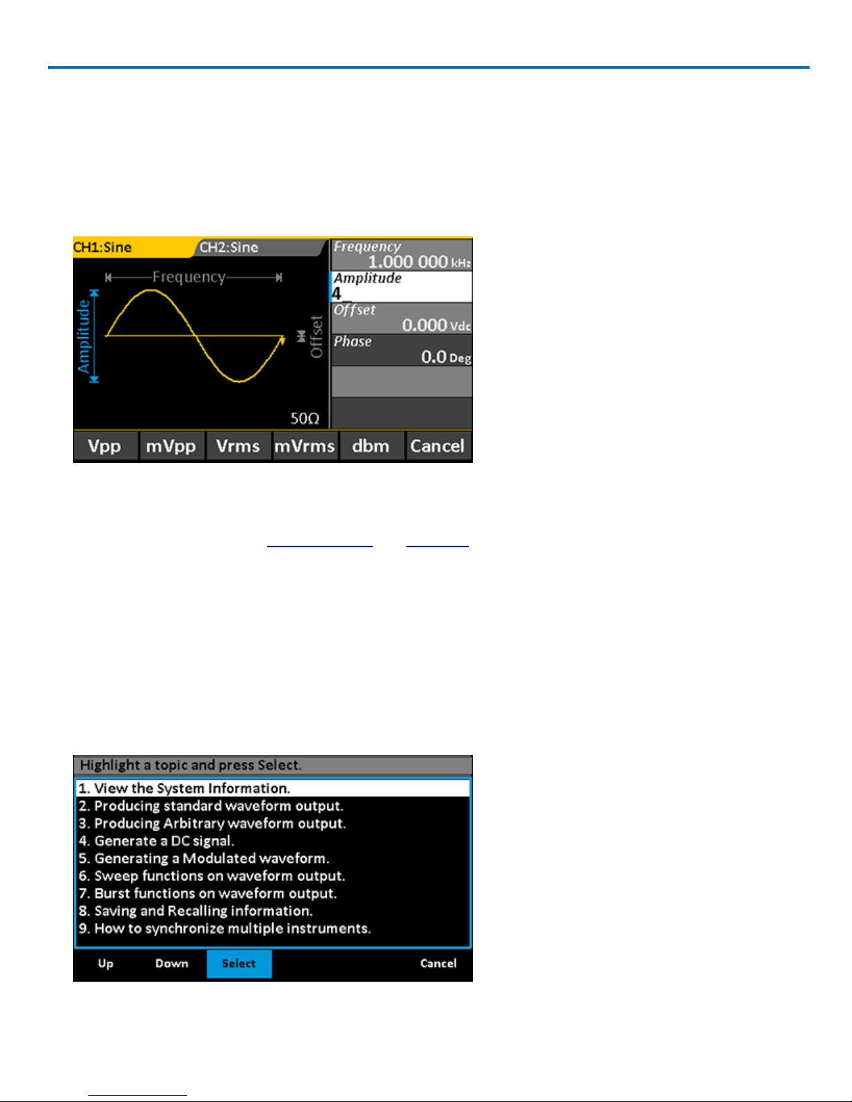
Using the Keypad
This method is required to change the unit of measure associated with the parameter value.
1. Select the parameter from the option menu using the softkey button. The parameter will appear blue on
the Parameter menu and white on the Parameter Value list.
2. Press the keypad buttons to enter the new value. The display will change to show a menu of unit s of measure.
3. If desired, press the softkey to select a new unit of measure.You will return to the parameter menu.
4. Use the softkeys to select the next parameter to edit.
The Keypad is also used during Self Calibration and Self Test functions.
Using WaveStation Help
Onboard Help provides brief topics to guide you while using the system. To use the Help:
1. Press the Help function button on the Front Panel to open the Help menu. A list of topics appears on the
display.
2. Press the Up or Down softkey buttons to navigate the list.
3. When the desired topic is highlighted on the display, press the Select softkey to view it.
4. Press Done to return to the menu of Help topics, or Cancel to exit the Help menu.
922869 Rev B
11
WaveStation 3000 Function and Arbitrary Waveform Generator
Generating Basic Waveforms
Follow this procedure to generate one of the five basic waveform types.
1. Choose your output channel by pressing the Ch1/Ch2function button until the correct tab is active on the
display.
NOTE: WaveStation defaults to the Channel 1 tab and Waveform menu whenever you power on, although
you can change this setting on the Utility menu. If Channel 1 is correct, skip to Step 2.
2. Press the Waveform function button to open the Waveform menu, then select the desired shape using the
softkey.The options are: Sine, Square, Ramp, Pulse, and Noise.
NOTE: The default and min/max settings for each waveform depend on your WaveStation model. See the
specifications maintained on the product datasheet at teledynelecroy.com.
You should see your waveform selection appear on the active Channel tab, along with the parameter
option menu and Parameter Value list.
12
922869 Rev B

Operator's Manual
3. Adjust parameters as necessary using either the Adjustment knob or the numeric keypad.
For all waveforms except Noise, adjust the values for:
l Frequency or Period.
l Amplitude and Offset, or absolute HighLevel and LowLevel of voltage.
For Sine waves, also adjust Phase.
For Square waves, also adjust:
l Phase
l DutyCycle, entered as the percentage of the High Level taking up the whole period.
For Ramp waves, also adjust Symmetry.
For Pulse waves, also adjust:
l Width or Duty Cycle
l Rise(ing Edge) or Fall(ing Edge)
l Delay
For Noise waves, adjust:
l Stdev
l Mean
4. When all parameters are configured, press the appropriate Output button to output the waveform, or go on
to apply Modulation, Sweep, or Burst signal conditioning before outputting.
NOTE: Noise waves cannot be modulated or swept. Pulse waves cannot be swept.
SEE ALSO:
Generating DC Waveforms
Generating Arbitrary Waveforms
Recalling Stored Waveforms
922869 Rev B
13

WaveStation 3000 Function and Arbitrary Waveform Generator
Generating a DC Waveform
DC waveforms cannot be conditioned using Mod(ulate), Sweep, or Burst.
1. Choose your output channel by pressing the Ch1/Ch2 function button until the correct tab is active on the
display.
NOTE: WaveStation defaults to the Channel 1 tab and Waveform menu whenever you power on, although
you can change this settingon the Utility menu. If Channel 1 is correct, skip to Step 2.
2. Press the Waveform function button to open the Waveform menu, then press the More 1 of 2 softkey.
3. Press the DC softkey.
4. Enter the DC Offset value.
5. Press the appropriate Output button to output the waveform.
SEE ALSO:
Generating Basic Waveforms
Generating Arbitrary Waveforms
Recalling Stored Waveforms
14
922869 Rev B

Operator's Manual
Generating an Arbitrary Waveform
WaveStation offers several built-in Arbitrary waveforms for selection, all of which can be further adjusted to
your needs.
1. Choose your output channel by pressing the Ch1/Ch2 function button until the correct tab is active on the
display.
NOTE: WaveStation defaults to the Channel 1 tab and Waveform menu whenever you power on, although
you can change this settingon the Utility menu. If Channel 1 is correct, skip to Step 2.
2. Press the Waveform function button to open the Waveform menu, then press the More 1 of 2 softkey.
3. Press the Arb softkey, then press the Built-in softkey. The display changes to show the first group of builtin arbitrary waveforms.
4. Press the softkeys to select different groups until you find the desired waveform, then turn the Adjust knob
until the waveform is highlighted white on the LCD.
5. Press Done to complete the selection. The LCD returns to the regular waveform display, where you should
see a diagram of the selected wave shape.
6. Adjust parameters as necessary using either the knob or the keypad.
7. When all parameters are set, press the appropriate Output button to begin outputting the waveform.
SEE ALSO:
Generating Basic Waveforms
Generating DC Waveforms
Recalling Stored Waveforms
922869 Rev B
15

WaveStation 3000 Function and Arbitrary Waveform Generator
Generating Modulated Waveforms
Sine, Square, Ramp, Pulse and Arb(itrary) waveforms all may be modulated using WaveStation. You can apply
Amplitude Modulation (AM), Frequency Modulation (FM), Amplitude Shift Keying Modulation (ASK), Frequency
Shift Keying Modulation (FSK), Phase Modulation (PM), Pulse-Width Modulation (PWM), or Double-Side Band
Amplitude Modulation (DSB-AM) depending on the type of carrier wave used.
Noise and DC waveforms cannot be modulated.
Also see:
Adjusting Parameters
Navigating Menus and Making Selections
Understanding the Display
Generating an AM Modulated Waveform
1. Generate a carrier wave of type Sine, Square, Ramp, or Arb(itrary).
2. Before outputting, press the Front Panel Mod function button. You should see "Mod" appear next to the
carrier wave type on the Channel tab, and the modulation parameter menu and value list on the display.
3. Press the Type softkey, then press the AM softkey.
4. Set the following AM parameters:
l Modulation Source - Internal or External. If External is selected, attach the modulation source to
the Modulation In connector on the Back Panel. You do not need to set any other parameters.
l AM Freq - modulating waveform frequency. The internal source frequency range is 2 MHz to 20
kHz.
l AM Depth - also referred to as Amplitude Range or percentage modulation. It's a percentage value
that varies from 1 to 120% . When set to 0%, the output amplitude is approximately half of the user
set amplitude value. When set to 100%, the output amplitude matches the amplitude set. When
using an external source, the AM depth is controlled by the voltage level of the connector attached
to Modulation In on the Back Panel. ±10 V corresponds to 100% of your current depth setting.
5. Press the appropriate channel Output button to begin outputting the waveform.
16
922869 Rev B

Operator's Manual
Generating an FM Modulated Waveform
1. Generate a carrier wave of type Sine, Square, Ramp, or Arb(itrary).
2. Before outputting, press the Front Panel Mod function button. You should see "Mod" appear next to the carrier wave type on the Channel tab, and the modulation parameter menu and value list on the display.
3. Press the Type softkey, then press the FM softkey.
4. Set the following FM parameters:
l Modulation Source - Internal or External. If External is selected, attach the modulation source to the
Modulation In connector on the Back Panel.
l FM Freq - modulating waveform frequency. The internal source frequency range is 2 MHz to 20 kHz.
You do not need to set FM Freq if using an external modulation source.
l FM Dev - maximum frequency deviation. The frequency deviation value should be ≤ the carrier wave-
form frequency. The sum of the deviation and the carrier waveform frequency should be ≤ the maximum frequency of the selected waveform. When using an external source, the deviation is
controlled by the voltage level of the connector attached to Modulation In on the Back Panel: +10 V
corresponds to the selected deviation, and -10 V to the negative selected deviation. So, a ±10 V input
results in an output FM deviation equal to the preset FM deviation.
5. Press the appropriate channel Output button to begin outputting the waveform.
Generating a PM Modulated Waveform
Modulated waveforms are one part carrier waveform; the other modulated. In Phase Modulation, the phase of
the carrier waveform varies with the instantaneous voltage level of the modulated waveform.
1. Generate a carrier wave of type Sine, Square, Ramp, or Arb(itrary).
2. Before outputting, press the Front Panel Mod function button. You should see "Mod" appear next to the carrier wave type on the Channel tab, and the modulation parameter menu and value list on the display.
3. Press the Type softkey, then press the PM softkey.
4. Set the following PM parameters:
l Modulation Source - Internal or External. If External is selected, attach the modulation source to the
Modulation In connector on the Back Panel.
l PM Freq - sets the frequency at which the output amplitude shifts between the carrier amplitude and
0. The internal source frequency range is 1 MHz to 50 kHz.You do not need to set PM Freq if using an
external modulation source.
l Phase Dev - sets the maximum phase deviation. Values range from 0° to 360°.
5. Press the appropriate channel Output button to begin outputting the waveform.
922869 Rev B
17

WaveStation 3000 Function and Arbitrary Waveform Generator
Generating an FSK Modulated Waveform
Frequency Shift Keying modulation is an output frequency that switches from the carrier waveform and hop
preset frequencies at a specific point. The specific frequency point where the output switches is the Key
Frequency. The Key Frequency is determined by the internal frequency generator or the signal voltage level
from the Trig/Gate/Fsk/Burst connector on the Back Panel.
1. Generate a carrier wave of type Sine, Square, Ramp, or Arb(itrary).
2. Before outputting, press the Front Panel Mod function button. You should see "Mod" appear next to the
carrier wave type on the Channel tab, and the modulation parameter menu and value list on the display.
3. Press the Type softkey, then press the FSK softkey.
4. Set the following FSK parameters:
l Modulation Source - Internal or External. If External is selected, attach the modulation source to
theModulation In connector on the Back Panel.
l Key Freq - the frequency at which the output frequency shifts between the carrier amplitude and
the hop frequency. The internal source frequency range is 1 mHz to 1 MHz. You do not need to set
Key Freq if using an external modulation source.
l Hop Freq - the desired hop frequency level (for variation from the set carrier waveform frequency).
5. Press the appropriate channel Output button to begin outputting the waveform.
Generating an ASK Modulated Waveform
Amplitude Shift Keying modulation represents digital data as variations in the amplitude of a carrier wave.
The amplitude of an analog carrier signal varies in accordance with the bit stream (modulating signal),
keeping frequency and phase constant.
1. Generate a carrier wave of type Sine, Square, Ramp, or Arb(itrary).
2. Before outputting, press the Front Panel Mod function button. You should see "Mod" appear next to the
carrier wave type on the Channel tab, and the modulation parameter menu and value list on the display.
3. Press the Type softkey, then press the ASK softkey.
4. Set the following ASK parameters:
l Modulation Source - Internal or External. If External is selected, attach the modulation source to
the Trig/Gate/FSK/Burst connector on the Back Panel. You do not need to set any other parameters.
l Key Freq - the frequency at which the output amplitude shifts between the carrier amplitude and 0.
The internal source frequency range is 2 MHz to 50 kHz.
5. Press the appropriate channel Output button to begin outputting the waveform.
18
922869 Rev B

Operator's Manual
Generating a DSB-AM Modulated Waveform
1. Generate a carrier wave of type Sine, Square, Ramp, or Arb(itrary).
2. Before outputting, press the Front Panel Mod function button. You should see "Mod" appear next to the carrier wave type on the Channel tab, and the modulation parameter menu and value list on the display.
3. Press the Type softkey, then press the DSB-AM softkey.
4. Set the following DSB-AM parameters:
l Modulation Source - Internal or External. If External is selected, attach the modulation source to the
Modulation In connector on the Back Panel. You do not need to set any other parameters.
l DSB Frequency - If using Internal source, set a DSB frequency of up to 50 KHz.
5. Press the appropriate channel Output button to begin outputting the waveform.
Generating a PWM Modulated Waveform
Pulse-Width Modulation is used exclusively with Pulse type waves.
1. Generate a carrier wave of type Pulse.
2. Before outputting, press the Front Panel Mod function button. You should see "Mod" appear next to the carrier wave type on the Channel tab, and the modulation parameter menu and value list on the display. The
modulation Type will be set to PWM.
3. Set the following PWM parameters:
l Modulation Source - Internal or External. If External is selected, attach the modulation source to the
Modulation In connector on the Back Panel. You do not need to set any other parameters.
l PWMFreq(uency) - the rate at which the pulse is modulated.
l Width Dev(iation) -modulating pulse width.
4. Press the appropriate channel Output button to begin outputting the waveform.
922869 Rev B
19

WaveStation 3000 Function and Arbitrary Waveform Generator
Generating Sweep Waveforms
Sine, Square, Ramp, and Arb(itrary) waveforms may be swept using a Frequency function, which sweeps
either from an absolute start frequency to stop frequency or across a frequency span at a specified sweep
rate.
Pulse, Noise, and DC waveforms cannot be swept.
1. Set up a basic wave of type SIne, Square, Ramp, or Arb.
2. Before outputting, press the Front Panel Sweep function button.
3. Set the following sweep parameters:
l Sweep Time - sets the overall sweep rate.
l StartFreq and StopFreq - the specific frequencies where the sweep begins and ends. If you choose
to set StartFreq and StopFreq, you do not set MidFreq and FreqSpan.
l MidFreq and FreqSpan - the frequency that must remain at the center of the sweep, and the overall
span or range that it may deviate from the MidFreq in either a positive or negative direction.
l Source - choose Internal, External, or Manual to manually start and stop the sweep. If External is
selected, connect the sweep trigger source to the Trig/Gate/Fsk/Burst connector on the Back
Panel.
l TrigOut - choose Off or Open. Open sends a trigger pulse on the rising edge of the waveform;
connect from the Trig/Gate/Fsk/Burst connector on the Back Panel.
l Linear or Log - choose either Linear or Logarithmic spacing.
l Direction - choose to sweep in either an Up or Down direction.
4. When all sweep parameters are set, press the appropriate Output button to begin outputting the wave-
form.
SEE ALSO:
Adjusting Parameters
Navigating Menus and Making Selections
Understanding the Display
20
922869 Rev B

Operator's Manual
Generating Burst Waveforms
Sine, Square, Ramp, Pulse, and Arb waveforms may utilize an N-Cycle Burst or a Gated Burst. Noise
waveforms utilize only a Gated Burst.
N-Cycle Burst
In this method, you either specify a number of cycles after which to begin the burst and its duration (period), or
set an infinite cycle and trigger the burst manually or upon an external event.
1. Generate a basic waveform of type Sine, Square, Ramp, Pulse, or Arb. Before outputting, press the Burst
function button.
2. Press the NCycle softkey until it is selected.
3. Set the following Burst parameters:
l Source - Choose Internal, External, or Manual. If you select External, connect the trigger source to the
Trig/Gate/Fsk/Burst connector on the Back Panel.
l Start Phase - Enter a specific phase value (in °) to define the starting point of the burst. The phase
varies from 0° to 360°; the default setting is 0°. For an Arbitrary waveform, 0° is the first waveform
point.
l Burst Period - If using Internal Source, enter the length of the burst period.
NOTE: The period time increases if necessary to allow the specified number of cycles in a burst. The
following formula is applied: Burst Period > Carrier Period × Burst Number.
l TrigOut (Internal and Manual Sources) or Edge (External Source) - Choose Up (rising edge), Down
(falling edge), or Off.
l Delay - Press the More softkey to display this option. Specify a span of time between the trigger
input and the start of the burst. The minimum delay amount is 240 ns.
l Cycles or Infinite - Press the More softkey to display these options. If Cycles is selected, enter the
desired number of repetitions (from 1 to 1,000,000). Infinite generates a continuous waveform that
only stops upon a trigger event. Choose External or Manual Source to use Infinite.
4. When all parameters are set, press the appropriate Output button.
5. If you selected Manual source, a red Trigger option appears on the Burst menu. Press the Trigger softkey
to manually start and stop the burst as the waveform is output.
922869 Rev B
21

WaveStation 3000 Function and Arbitrary Waveform Generator
Gated Burst
This method sets a gate on the waveform to mark the burst period.
1. Generate a basic waveform.
2. Before outputting, press the Burst function button.
3. Press the Gated softkey until it is selected.
4. Enter the Start Phase value (in °) to define the starting point of the burst. The phase varies from 0° to
360°; the default setting is 0°. For an Arbitrary waveform, 0° is the first waveform point.
5. Choose either Positive or NegativePolarity.
6. Press the appropriate Output button to begin outputting the waveform.
22
922869 Rev B

Operator's Manual
Using External Trigger
The back-panel Ext Trig/Gate/FSK/Burst connector is a multi-purpose input used to accept the External
Source for several modes.
Triggered Sweep Mode
If using External Source to trigger a Sweep wave, the instrument outputs a single sweep when an edge of the
correct polarity is received on the Ext Trig connector.
Triggered N-Cycle Burst Mode
If using External Source to trigger a Burst wave, the instrument outputs a waveform with specified number of
cycles (burst count) each time a trigger is received on the Ext Trig connector.
Externally Gated Burst Mode
If using External Source for a Gated Burst wave, the instrument outputs a continuous waveform when the Gate
signal is true. When the external Gate signal goes false, the current waveform cycle completes, then the
instrument stops while remaining at a voltage level corresponding to the starting burst phase. For Noise
waveforms, output stops as soon as the Gate signal goes false.
Externally Modulated FSK Mode
If using External Source for an FSK modulated wave, the carrier frequency is output when a logic low level is
present on the FSK connector. When a logic high level is present, hop frequency is output. Maximum external
FSK rate is 100 kHz.
922869 Rev B
23

WaveStation 3000 Function and Arbitrary Waveform Generator
Using Sync Out
All standard output functions (except DC and Noise) have a corresponding Sync signal that can be sent
through the Sync Out connector on the back panel. This is useful for synchronizing different devices to the
occurrence of a particular waveform event.
Waveform Type Sync Signal Reference
Non-modulated carrier signal
AM, FM, and PM Modulated
(internal modulation source)
ASK and FSK Modulated keying frequency
Sweep TTL level high (at start), then at a frequency equal to the sweep time
Burst level high (at start)
External Gated Burst external gated signal
Pulse pulse signal with a fixed positive pulse width more than 50 ns
modulated signal
NOTE: If an output waveform is inverted, the corresponding Sync signal does not also invert.
To enable/disable the Sync signal output:
1. Press the Utility function button.
2. Press the Sync softkey.
3. Press the State softkey until On or Off appears.
4. Select the Channel to use as the Sync reference.
5. Press Done.
When the Sync signal is disabled, the output voltage of the [Sync] connector is set to low level.
24
922869 Rev B

Operator's Manual
Save/Recall
The WaveStation offers onboard storage of setup (state) files. Ten internal memory banks are provided for you
to quickly save work and recall it to the instrument when needed. Setup files can also be saved to and from
external drives for quick transfer of state data between devices.
You may also save waveform (data) files created on Teledyne LeCroy oscilloscopes or in the WaveStation PC
software to the WaveStation for recall and output at a future time. WaveStation 3000 has two banks to
accommodate waveform files up to 16K and 512K, allowing you to make and store longer acquisitions.
Save/Recall Browser
You'll see a different LCD screen when performing Save/Recall than when generating waveforms. The screen
is divided into three principal sections:
l File name at the top of the display
l Drive/folder list at the left of the display
l File list at the right of the display
Switch between the folder and file sections of the display by pressing the Browsersoftkey on the Save/Recall
option menu. Scroll each list using the Adjustknob.
Keyboard
The default name for internal setup files is SET<number>. This is appended to the STATE to create the full
setup name that appears at the top of the Browser display (e.g., STATE1:SET01). The number increments each
time a new setup is saved. Similarly, setup files created on an external drive are by default named WST3000,
WST3001, etc. These autogenerated file names can be changed to something more descriptive using the
keyboard display.
922869 Rev B
25

WaveStation 3000 Function and Arbitrary Waveform Generator
When you first press the Save softkey during the Save procedure, the keyboard is displayed with the default
File Name shown at the top. To change the name:
1. Press the Delete softkey to clear characters from the File Name field.
2. Use the Adjust knob and the Up and Down softkeys to navigate to characters on the keyboard.
3. When the desired character is selected, press the Select softkey to insert it in the File Name field.
4. Repeat until you have entered the desired File Name, then press the Save softkey.
Save/Recall Setups
1. If saving to (or recalling from) a USB drive, insert the drive into the USB host port on the front of the
WaveStation.
2. Press the Utility function button, then press the Store/Recall softkey.
3. Press the FileType softkey until State is selected.
4. WaveStation defaults to the Local (C:) folder. If using an external drive, press the Browser softkey until
Directory is selected, then turn the Adjust knob until USB Device is selected. Otherwise, skip this step.
5. Press the Browser softkey to select File. The cursor switches to the file list at the right side of the display.
6. If using internal storage, turn the Adjust knob to select the desired STATE memory bank (1-10).
NOTE: Any prior data stored in an internal memory will be overwritten when you save. If possible, select a
State that does not already have a setup file associated with it.
7. To save the current setup:
l Press the Save softkey.
l If desired, use the keyboard to change the default File Name.
To restore the WaveStation to the selected setup, press Recall.
26
922869 Rev B

Operator's Manual
Save/Recall Waveforms
Waveforms files created outside the WaveStation can be saved to and recalled from a memory bank on the
WaveStation.
1. Insert the drive into the USB host port on the front of the WaveStation.
2. Press the Utility function button, then press the Store/Recall softkey.
3. Press the FileType softkey until Data is selected.
4. Press the Browser softkey until Directory is selected, then turn the Adjust knob until USB Device is
selected.
5. Press the Browser softkey to select File. The cursor switches to the file list at the right side of the display.
6. Turn the Adjust knob to select the desired memory bank, ARB(16k) or ARB(512k), then press Select.The dis-
play changes to show a table of waveform files.
7. Turn the Adjust knob until the desired cell/file is selected.
NOTE: If possible, choose an empty cell when saving a file. Any prior data saved in that location will be
overwritten.
8. Press Save to store the file, or Recall to output it using WaveStation.
NOTE: 512K files must be output via Channel 2.
9. When saving data files, use the keyboard to change the File Name.
Delete Setup or Waveform File
Follow the Save/Recall procedures to navigate to the setup or data file. With the file selected from the File List
at the right side of the Browser, press the Delete softkey.
Copy Channel Settings
The setups from either WaveStation channel can be quickly copied to the other. Complete your waveform
configuration on the source channel, then:
1. Press the Utility function button.
2. Press the Channel Copy softkey.
3. Press either CH1=>CH2 or CH2=>CH1, depending on the direction you wish to copy.
4. Press Done.
922869 Rev B
27

WaveStation 3000 Function and Arbitrary Waveform Generator
Changing System Settings
Many default WaveStation settings can be modified through the Utility menu. Follow the procedures below to
change Output and System settings.
See the Using Sync Out, Remote Control, and Maintenance sections for instructions on using other Utility
menu options.
Also see Restoring Default Settings.
Output
This setting changes the output Voltage and Polarity on the generated waveform. For output over 10 V pk-pk,
use the HighZ setting.
1. Press the Utility function button.
2. Press the Output Setup softkey.
3. Press the Load softkey until either 50Ω or HighZ is selected.
4. Press Polarity to select either Normal or Invert.
5. Press Done.
USB Output
The USB Type B port on the back of the WaveStation can be configured to output either:
l USBRAW
l USBTMC, used for remote control and WaveStation PC software
1. Press the Utility function button.
2. Press the Interface softkey.
3. Press the USB Setup softkey.
4. Press either USBRAW or USBTMC.
5. Press Done.
Number Format
1. Press the Utility function button.
2. Press the More softkey, then press System and Number Format.
3. Choose a Point style of either period (.) or comma (,). This character is placed after the first thousand.
4. Choose a Separator of:
l On - places the other Point character (period or comma) between whole units and decimals.
l Space - uses a space rather than a character to separate whole units and decimals.
l Off- no separator.
5. Press Done.
28
922869 Rev B

Operator's Manual
Power On Setting
The WaveStation default is to revert to the factory settings after power down. To retain the last saved settings
and restore them at power on:
1. Press the Utility function button.
2. Press the More softkey, then press System.
3. Press PowerOn until Last is selected.
4. Press More, then press Done.
Sound
The WaveStation default is to emit a low beep whenever a control is pressed. To turn off the sound:
1. Press the Utility function button.
2. Press the More softkey, then press System.
3. Press the Beep softkey until Off is selected.
4. Press More, then press Done.
Screen Saver
The WaveStation is set to turn off the LCD if there is no activity for 15 minutes. To change this setting:
1. Press the Utility function button.
2. Press the More softkey, then press System.
3. Press More, then press ScrnSvr.
4. Choose another time out value from the menu, or Off to disable this feature.
5. Press Cancel to return to the previous menu, then press Done.
NOTE: Only the LCD is disabled after the time out to preserve the display. The WaveStation continues to run
and generate waveforms.
Clock Source
By default, WaveStation utilizes an internal 10 MHz reference clock. You can choose to instead input an
external reference clock. To change the reference clock:
1. Connect the clock to the 10 MHz Input connector on the Back Panel.
2. Press the Utility function button.
3. Press the More softkey, then press System.
4. Press More, then press CLKSourceuntil External is selected.
5. Press Done.
922869 Rev B
29

WaveStation 3000 Function and Arbitrary Waveform Generator
Restoring the Default Settings
To restore the WaveStation to the factory default settings (shown in the table below):
1. Press the Utility function button.
2. Press the More softkey, then press System.
3. Press Set to Default. After a moment, the screen will blink and reset to the CH1:Sine wave parameter
menu.
SubSystem & Parameter Default Values
Output
Function Sine Wave
Frequency 1 kHz
Amplitude/Offset 100 mVpp/0 V DC
Phase 0°
Terminals High Z
Modulation
Carrier 1 kHz Sine Wave
Modulating 100 Hz Sine Wave
AM Depth 100%
FM Deviation 500 Hz
Key Freq 100 Hz
FSK Hop Frequency 1 MHz
Phase Deviation 180°
Sweep
Start/Stop Frequency 100 Hz/1.9 kHz
Sweep Time 1 S
Trig Out Off
Mode Linear
Direction Up
Burst
Period 10 ms
Phase 0°
Count 1 Cycle
Trig Off
Trigger
Source Internal
30
922869 Rev B

Operator's Manual
Remote Control of WaveStation
WaveStation can be remote controlled using either a USB-GPIB or USBTMC connection. For a complete list of
remote control commands and their syntax, refer to the WaveStation SCPI (Standard Commands for
Programmable Instruments) Reference Manual available at:
teledynelecroy.com/wavestation.
NOTE: WaveStation remote commands must not contain termination characters of any kind. This includes Null
characters.
GPIB Remote Control
WaveStation conforms to the IEEE 488.2 GPIB standard. GPIB controls can be used to interface WaveStation
with other GPIB compatible devices, including Teledyne LeCroy oscilloscopes.
NOTE:The GPIB interface on the WaveStation supports Device mode only, not Controller.
GPIB remote control of WaveStation requires the use of the USB-GPIB converter cable included with the
product. The USB connection from the WaveStation provides all necessary power to the converter.
To utilize GPIBremote control:
l Prepare your control files according to the conventions documented in the WaveStation SCPI Command
Reference.
l Connect the USB-GPIB converter cable.
l Configure the WaveStation for GPIB communication.
Connecting the USB-GPIB Converter
Connect the USB-GPIB converter from the USB A port on the front of the WaveStation to the GPIBbus on the
controller.
The converter has two LED indicators on it showing when the device is powered on and Ready (red), and Active
(green) and transmitting data.
NOTE: Do not disconnect either end of the converter until all equipment is powered down.
Configuring WaveStation for GPIB
1. Check the GPIB address assigned to WaveStation on the controller. WaveStation uses 18 by default; if the
controller is using a different number, you will need to change it on either side to match.
2. Press the Utility function button.
3. Press the Interface softkey.
4. Press the GPIB softkey.
5. If necessary, use the number keypad to enter the correct GPIB address.
6. Press Done.
922869 Rev B
31

WaveStation 3000 Function and Arbitrary Waveform Generator
USBTMC Remote Control
To utilize a USBTMC connection:
l Install NI-VISA on the controller. See the WaveStation SCPI Command Reference for configuration
details.
l Prepare your control files according to the conventions documented in the WaveStation SCPI Com-
mand Reference.
l Connect a USB 2.0 Type A-B cable from the USB B port on the back of the WaveStation to a USB A port
on the controller.
l Configure WaveStation for USBTMC output.
Using LabView Software
Either the USB or GPIB interface can be utilized with the free LabView Driver to remote control the
WaveStation using LabView projects.
The download includes three sample LabView projects that you can use to set up your own LabView
workflow.
Waveform files saved in the WaveStation PC Software must be saved in SendWave CSV format to be
exchanged with LabView.
See the WaveStation SCPI for instructions on installing the LabView driver.
32
922869 Rev B

Operator's Manual
Using WaveStation PC Software
The WaveStation PC Software allows you to exchange waveform files between the WaveStation and your PC.
The software includes tools to help you modify or generate new files on the PC, then save them to one of
WaveStation's internal memory banks for future output.
NOTE: Waveform files are a scalar representation of the waveform data. Adjust the amplitude, frequency, and
offset as desired on the WaveStation.
Minimum System Requirements
l Operating system Windows® Vista 32-Bit Version, Windows® 7 32-Bit Version, Windows 8
l Pentium® IV processor
l 1 Gb RAM
l 150 Mb hard disk available space for software set‐up
l Video resolution 800 X 600
l USB 2.0 connections
Updates
Teledyne LeCroy periodically releases updates of the WaveStation PC Software providing new features,
enhancements, and software corrections. These updates are available free from:
teledynelecroy.com/support/softwaredownload/
Installing WaveStation PC Drivers and Software
Follow these steps in this exact order to install the WaveStation PC drivers and software:
1. Download the latest version of WaveStation PC Software compatible with your WaveStation model from teledynelecroy.com. Unzip the installer archive on the PC where you will install the software.
2. With both the WaveStation and the PC turned on, connect the 1 m USB 2.0 Type A- B Cable from the USB B
port on the back of the WaveStation to a USB A port on your PC. If shown, you can close pop-ups on the PC
resulting from the connection of the USB cable.
3. Install the drivers:
l On the PC, navigate to the location for Universal Serial Bus controllers (usually under Device Man-
ager).
l Right-click on LeCroy Series Function/Arbitrary Waveform Generator and select Update Driver Soft-
ware (depending on your OS, you may have to navigate through the Properties dialog to this selec-
tion).
l Choose to Browse my computer for driver softwareand navigate to the WaveStation PC Software
→USB Driver folder. Select the drivers for either 32 or 64-Bit installation.
l If alerted by Windows Security, choose to Install this driver software anyway.
4. After the driver installation is complete, navigate to the WaveStation PC Software → Setup folder and run
WaveStation_setup.exe. Follow the prompts on the installer dialogs.
922869 Rev B
33

WaveStation 3000 Function and Arbitrary Waveform Generator
Connecting WaveStation to the PC
To re-establish the link between the WaveStation and your PC after the initial software installation:
1. Power on WaveStation.
2. With the PC turned on, connect the USB Type B-A cable from the rear USB B port on the WaveStation to a
USB A port on the PC.
3. Launch the WaveStation PC software.
Reading Files from WaveStation on a PC
You can retrieve any stored or arbitrary waveform file from the WaveStation and send it to the WaveStation
PC software for modification.
Complete the preliminary steps to:
l Install WaveStation PC drivers and software.
l Make the connection from WaveStation to the PC.
Starting from WaveStation
1. Follow the steps to generate an arbitrary waveform, choosing either one of the Built-In or Stored Wforms.
2. In the WaveStation PC Software, choose Communication → Read wave from the menu bar.
3. Select the device you want to read the wave from the Device List. The software detects multiple devices.
4. Select the stored or built-in waveform from the Wave List. You will see all the wave files stored on the
device.
34
922869 Rev B

5. Click Read Wave.
6. Use the PC software tools to modify the file as desired.
Operator's Manual
Starting from the PC
1. Click the Read wave button on the lower part of the screen
2. On theRead wave pop-up, select the desired waveform from the Wave List. This list will include the names
of all the built-in arbitrary and saved waveforms.
922869 Rev B
35

WaveStation 3000 Function and Arbitrary Waveform Generator
3. Use the PC software tools to modify the file as desired.
36
922869 Rev B

Operator's Manual
Sending Waveform Files from a PC to WaveStation
New waveform files generated in the WaveStation PC Software can be sent and stored on the WaveStatation
for future use.
Complete the preliminary steps to:
l Install WaveStation PC drivers and software.
l Make the connection from WaveStation to the PC.
1. Launch the WaveStation PC Software and select File → New from the menu bar. The Property setting pop-
up is shown.
2. Provide a name for you Wave and details for:
l Samples - choose either 16k or 512k; the file will be stored in the respective bank.
l VPP - defaults to 20 Vpp.
l Quantify - defaults to 14.
l Frequencyor Period of the waveform.
Click the Ok button when finished.
NOTE: Vpp can be changed in the next step using the Type buttons after the default waveform appears on
the WaveStation PC software screen.
922869 Rev B
37

WaveStation 3000 Function and Arbitrary Waveform Generator
3. The resulting waveform appears on screen. Use the Waveform Type buttons or using various Waveform
Drawing Tools to modify it as desired.
4. With your waveform setup as desired, click Save.
5. Choose Communication → Send wave from the menu bar, or click the Send wave button at the bottom of
the window.
38
922869 Rev B

6. On the Send Wave pop-up, choose the:
l Target WaveStation from the Device List. All connected devices will appear for selection.
l Store locationArb 1 or Arb2 (depending on the size of the file you're saving).
l Name of the file.
l Transfer channel. 512k files can only be sent over CH2.
Click Send.
Operator's Manual
A status message should appear indicating the read completed successfully.
NOTE: When you save a data file to a location already containing previously stored information, your new
information always overwrites the old. If you choose the wrong bank or transfer channel for the size of the
file, you'll see the following error message.
922869 Rev B
39

WaveStation 3000 Function and Arbitrary Waveform Generator
Save Waveform to .CSV File
Waveform data can be saved in two different formats using the WaveStation PC software:
l Comma-Separated Values (*.CSV), - includes all usual waveform parameters such as frequency, ampli-
tude, etc. in a comma-delimited file. The file header shows the saved data.
l SendWave .CSV - includes just the amplitude data in a format that can be exchanged with LabView
software.
To save a waveform:
1. Choose File > Save.
2. Browse to the folder where you wish to save the file.
3. Enter a File Name.
4. Chose to Save as Type *.CSV or SendWave CSV.
5. Click Save.
40
922869 Rev B

Operator's Manual
Maintaining WaveStation
Cleaning
Clean only the exterior of the instrument using a soft cloth moistened with water or an alcohol solution. Do not
use harsh chemicals or abrasive elements. Under no circumstances submerge the instrument or allow
moisture to penetrate it. Avoid electric shock by unplugging the power cord from the AC outlet before cleaning.
CAUTION. Do not attempt to clean internal parts. Refer to qualified service personnel.
Updating WaveStation Firmware
WaveSation firmware updates are released periodically and are available for free. It is recommended to update
your WaveStation whenever there is a new firmware release to keep it performing optimally.
To check your current firmware version, press Utility→ More→ Edit Infoto display the WaveStation details
screen.
Download the latest firmware for the WaveStation 3000 series Function/Arbitrary waveform generators from
teledynelecroy.com/support/softwaredownload/.
To install firmware updates:
1. Extract the firmware file, <filename>.ads, and save it to a USB drive.
2. Power on the WaveStation, and plug the USB drive into the Front Panel USB port.
3. Press the Utility function button, then press the More and Update softkeys.
4. You'll see the Browser display used to Save/Recall files. Press the Browser softkey to select Directory,
then turn the Adjust knob to select USB Drive. If the file is inside a sub-folder, press the Right Cursor button below the Adjust knob to open the folder.
5. Change Browser to File, and navigate to <filename>.ads.
6. Select the *.ads file and press Recall.
7. Follow the instructions on screen to begin the update.
NOTE: When the update starts, you will see the message “System updating… Please don’t shutdown your
WaveStation during the updating procedure.” Do not power off the WaveStation for any reason during this
process. Doing so can render the WaveStation inoperable.
8. When the update is complete, power off and restart the WaveStation.
922869 Rev B
41

WaveStation 3000 Function and Arbitrary Waveform Generator
Self Tests
These tests enable you to determine if the WaveStation controls are functioning properly. It is recommended
to perform them periodically. If you discover a malfunction during a test, contact your nearest Teledyne
LeCroy service center for instructions. You may or may not need to return the product for repair.
Screen Test
This test enables you to check the color registration of the LCD.
1. Press the Utility function button.
2. Press the More softkey, then press Test/Cal.
3. Press SelfTest, then ScrTest. You will see the display change to red.
4. Following the directions on the display, continue to press the number 7 on the keypad to cycle through
red, green, and blue. Press the number 8 on the keypad to exit the test.
Key Test
This test determines if the WaveStation CPU is receiving proper input from the Front Panel controls.
1. Press the Utility function button.
2. Press the More softkey, then press Test/Cal.
3. Press SelfTest, then KeyTest. The display changes to show a simulation of the Front Panel.
42
922869 Rev B

Operator's Manual
4. Press each button and knob on the Front Panel in turn. As you press them, you should see the corresponding block on the simulation turn blue, indicating proper functioning. If any block fails to change, the
control is malfunctioning.
5. Press the number 8 on the keypad three times to exit the test.
LED Test
This test determines whether the LEDs that light the Function buttons on the Front Panel buttons are working
properly.
1. Press the Utility function button.
2. Press the More softkey, then press Test/Cal.
3. Press SelfTest, then LEDTest. The display changes to show a simulation of the Front Panel exactly like the
one in the Key Test.
4. Continue to press the number 7 on the keypad. Each block on the simulation that corresponds to a Function button turns blue, while the button itself lights up, indicating proper functioning. If any block or button
fails to light, the control is malfunctioning.
5. Press the number 8 on the keypad three times to exit the test.
Self Calibration
WaveStation includes a self-calibration routine that makes gain and phase adjustments. Run the self
calibration on an as needed basis.
Contact your nearest Teledyne LeCroy service center to schedule a factory calibration once per year.
1. Press the Utility function button.
2. Press the More softkey, then press Test/Cal.
3. Press SelfAdjust. You will see a progress bar appear over the display. Wait until the calibration completes,
then press any Function button to exit.
922869 Rev B
43

WaveStation 3000 Function and Arbitrary Waveform Generator
Returning a Product for Service
Contact your local Teledyne LeCroy service center for calibration or other service. If the product cannot be
serviced on location, the service center will give you a Return Material Authorization (RMA) code and instruct
you where to ship the product. All products returned to the factory must have an RMA.
Return shipments must be prepaid. Teledyne LeCroy cannot accept COD or Collect shipments. We
recommend air-freighting. Insure the item you’re returning for at least the replacement cost.
1. Remove all accessories from the device. Do not include the manual.
2. Pack the product in its case, surrounded by the original packing material (or equivalent).
3. Label the case with a tag containing:
l The RMA
l Name and address of the owner
l Product model and serial number
l Description of failure or requisite service
4. Pack the product case in a cardboard shipping box with adequate padding to avoid damage in transit.
5. Mark the outside of the box with the shipping address given to you by Teledyne LeCroy; be sure to add
the following:
l ATTN: <RMA code assigned by Teledyne LeCroy>
l FRAGILE
6. If returning a product to a different country:
l Mark the shipment as a "Return of US manufactured goods for warranty repair/recalibration."
l If there is a cost for the service, list the cost in the Value column and the original purchase price
"For insurance purposes only."
l Be very specific about the reason for shipment. Duties may have to be paid on the value of the serv-
ice.
Extended warranty, calibration, and upgrade plans are available for purchase. Contact your Teledyne LeCroy
sales representative to purchase a service plan.
44
922869 Rev B

Operator's Manual
Reference
Specifications
The most current specification information regarding your product are maintained on the Teledyne LeCroy
website atteledynelecroy.com. Specifications are subject to change without notice.
Certifications
EMC Compliance
EC DECLARATION OF CONFORMITY- EMC
The oscilloscope meets intent of EC Directive 2004/108/EC for Electromagnetic Compatibility. Compliance
was demonstrated to the following specifications as listed in the Official Journal of the European
Communities:
EN 61326-1:2006, EN 61326-2-1:2006 EMC requirements for electrical equipment for measurement, control,
and laboratory use.
Electromagnetic Emissions:
CISPR 11:2003, Radiated and Conducted Emissions Group 1, Class A
EN 61000-3-2:2006 Harmonic Current Emissions, Class A
EN 61000-3-3/A2:2005 Voltage Fluctuations and Flickers, Pst = 1
Electromagnetic Immunity:
EN 61000-4-2:2001 Electrostatic Discharge, 4 kV contact, 8 kV air, 4 kV vertical/horizontal coupling planes
EN 61000-4-3:2006 RF Radiated Electromagnetic Field, 3 V/m, 80-1000 MHz; 3 V/m, 1400 MHz - 2 GHz; 1 V/m,
2 GHz - 2.7 GHz
EN 61000-4-4:2004 Electrical Fast Transient/Burst, 1 kV on power supply lines, 0.5 kV on I/O signal data and
control lines
EN 61000-4-5:2006 Power line Surge, 1 kV AC Mains, L-N, L-PE, N-PE
EN 61000-4-6:2007 RF Conducted Electromagnetic Field, 3 Vrms, 0.15 MHz - 80 MHz
EN 61000-4-11:2004 Mains Dips and Interruptions, 0%/1 cycle, 70%/25 cycles, 0%/250 cycles
1 To ensure compliance with all applicable EMC standards, high quality shielded interface cables should be used.
2 Emissions which exceed the levels required by this standard may occur when the oscilloscope is connected to a test object.
3 This product is intended for use in nonresidential areas only. Use in residential areas may cause electromagnetic interference.
4 Meets Performance Criteria “B” limits of the respective standard: during the disturbance, product undergoes a temporary degradation
or loss of function or performance which is self-recoverable.
5 Performance Criteria “C” applied for 70%/25 cycle voltage dips and for 0%/250 cycle voltage interruption test levels per EN61000-4-
11.
4
1
2 3
4
4
4
4
4 5
922869 Rev B
45

WaveStation 3000 Function and Arbitrary Waveform Generator
European Contact:
Teledyne LeCroy Europe GmbH
Waldhofer Str 104
D-69123 Heidelberg
Germany
Tel: (49) 6221 82700
AUSTRALIA & NEW ZEALAND DECLARATION OF CONFORMITY– EMC
Oscilloscope complies with the EMC provision of the Radio Communications Act per the following standards,
in accordance with requirements imposed by Australian Communication and Media Authority (ACMA):
CISPR 11:2003 Radiated and Conducted Emissions, Group 1, Class A, in accordance with EN61326-1:2006
and EN61326-2-1:2006.
Australia / New Zealand Contacts:
Vicom Australia Ltd.
1064 Centre Road
Oakleigh, South Victoria 3167
Australia
Australia Vicom New Zealand Ltd.
60 Grafton Road
Auckland
New Zealand
Safety Compliance
EC DECLARATION OF CONFORMITY– LOW VOLTAGE
The oscilloscope meets intent of EC Directive 2006/95/EC for Product Safety. Compliance was demonstrated
to the following specifications as listed in the Official Journal of the European Communities:
EN 61010-1:2010 Safety requirements for electrical equipment for measurement, control, and laboratory use
– Part 1: General requirements
EN 61010-2:030:2010 Safety requirements for electrical equipment for measurement, control, and laboratory
use – Part 2-030: Particular requirements for testing and measuring circuits
The design of the instrument has been verified to conform to the following limits put forth by these
standards:
l Overvoltage Category II: equipment intended to be supplied from the building wiring with a nominal
supply voltage up to 300V.
l Measurement Category 0: measurement terminals that are not intended to be directly connected to the
MAINS supply.
l Pollution Degree 2: operating environment where normally only dry, non-conductive pollution occurs.
Occasionally a temporary conductivity that is caused by condensation must be expected. This location
is a typical office/home environment.
l Protection Class I: grounded equipment in which protection against electric shock is achieved by basic
insulation and a connection to the protective ground conductor in the building wiring.
U.S. NATIONALLYRECOGNIZED AGENCY CERTIFICATION
The oscilloscope has been certified by Underwriters Laboratories (UL) to conform to the following safety
standard and bears UL Listing Mark:
UL 61010-1 Third Edition – Safety standard for electrical measuring and test equipment.
46
922869 Rev B

Operator's Manual
CANADIAN CERTIFICATION
The oscilloscope has been certified by Underwriters Laboratories (UL) to conform to the following safety
standard and bears cUL Listing Mark:
CAN/CSA-C22.2 No. 61010-1-12. Safety requirements for electrical equipment for measurement, control and
laboratory use.
Environmental Compliance
END-OF-LIFE HANDLING
The instrument is marked with this symbol to indicate that it complies with the applicable
European Union requirements to Directives 2002/96/EC and 2006/66/EC on Waste Electrical and
Electronic Equipment (WEEE) and Batteries.
The instrument is subject to disposal and recycling regulations that vary by country and region.
Many countries prohibit the disposal of waste electronic equipment in standard waste
receptacles. For more information about proper disposal and recycling of your Teledyne LeCroy
product, please visit teledynelecroy.com/recycle.
RESTRICTION OF HAZARDOUS SUBSTANCES (ROHS)
This product and its accessories conform to the 2011/65/EU RoHS2 Directive, as it is classified as Industrial
Monitoring and Control Equipment (per Article 3, Paragraph 24) and is exempt from RoHS compliance until 22
July 2017 (per Article 4, Paragraph 3).
922869 Rev B
47

WaveStation 3000 Function and Arbitrary Waveform Generator
Warranty
THE WARRANTY BELOW REPLACES ALL OTHER WARRANTIES, EXPRESSED OR IMPLIED, INCLUDING BUT
NOT LIMITED TO ANY IMPLIED WARRANTY OF MERCHANTABILITY, FITNESS, OR ADEQUACY FOR ANY
PARTICULAR PURPOSE OR USE. TELEDYNE LECROY SHALL NOT BE LIABLE FOR ANY SPECIAL, INCIDENTAL,
OR CONSEQUENTIAL DAMAGES, WHETHER IN CONTRACT OR OTHERWISE. THE CUSTOMER IS RESPONSIBLE
FOR THE TRANSPORTATION AND INSURANCE CHARGES FOR THE RETURN OF PRODUCTS TO THE SERVICE
FACILITY. TELEDYNE LECROY WILL RETURN ALL PRODUCTS UNDER WARRANTY WITH TRANSPORT
PREPAID.
The product is warranted for normal use and operation, within specifications, for a period of three years from
shipment. Teledyne LeCroy will either repair or, at our option, replace any product returned to one of our
authorized service centers within this period. However, in order to do this we must first examine the product
and find that it is defective due to workmanship or materials and not due to misuse, neglect, accident, or
abnormal conditions or operation.
Teledyne LeCroy shall not be responsible for any defect, damage, or failure caused by any of the following: a)
attempted repairs or installations by personnel other than Teledyne LeCroy representatives or b) improper
connection to incompatible equipment, or c) for any damage or malfunction caused by the use of nonTeledyne LeCroy supplies. Furthermore, Teledyne LeCroy shall not be obligated to service a product that has
been modified or integrated where the modification or integration increases the task duration or difficulty of
servicing the oscilloscope. Spare and replacement parts, and repairs, all have a 90-day warranty.
Products not made by Teledyne LeCroy are covered solely by the warranty of the original equipment
manufacturer.
48
922869 Rev B

Contact Teledyne LeCroy
United States and Canada
- World Wide Corporate Office
Teledyne LeCroy Corporation
700 Chestnut Ridge Road
Chestnut Ridge, NY, 10977-6499, USA
Ph: 800-553-2769 / 845-425-2000
FAX: 845-578-5985
teledynelecroy.com
Support:
contact.corp@teledynelecroy.com
Sales:
customersupport@teledynelecroy.com
United States Protocol Solutions Group
Teledyne LeCroy Corporation
3385 Scott Boulevard
Santa Clara, CA, 95054, USA
FAX: 408-727-0800
teledynelecroy.com
Sales and Service:
Ph: 800-909-7211 / 408-727-6600
contact.corp@teledynelecroy.com
Support:
Ph: 800-909-7112 / 408-653-1260
psgsupport@teledynelecroy.com
European Headquarters
Teledyne LeCroy SA
4, Rue Moïse Marcinhes
Case postale 341
1217 Meyrin 1
Geneva, Switzerland
Ph: + 41 22 719 2228 / 2323 / 2277
FAX: +41 22 719 2233
contact.sa@teledynelecroy.com
applications.indirect@teledynelecroy.com
teledynelecroy.com/europe
Protocol Analyzers:
Ph: +44 12 765 03971
WaveStation 3000 Function and Arbitrary Waveform Generator
Singapore, Protocol Analyzers
Genetron Singapore Pte Ltd.
37 Kallang Pudding Road, #08-08
Tong Lee Building Block B
Singapore 349315
Ph: ++ 65 9760-4682
China
Teledyne LeCroy Corporation Beijing
Rm. 2001
Unit A, Horizon Plaza
No. 6, Zhichun Road, Haidian District
Beijing 100088, China
Ph: ++86 10 8280 0318 / 0319 / 0320
FAX:++86 10 8280 0316
Service:
Rm. 2002
Ph: ++86 10 8280 0245
Taiwan
LeColn Technology Co Ltd.
Far East Century Park, C3, 9F
No. 2, Chien-8th Road,
Chung-Ho Dist., New Taipei City, Taiwan
Ph: ++ 886 2 8226 1366
FAX: ++ 886 2 8226 1368
Korea
Teledyne LeCroy Korea
10th fl.Ildong Bldg.
968-5 Daechi-dong, Gangnam-gu
Seoul 135-280, Korea
Ph: ++ 82 2 3452 0400
FAX: ++ 82 2 3452 0490
Japan
Teledyne LeCroy Japan
Hobunsya Funchu Bldg, 3F
3-11-5, Midori-cho, Fuchu-Shi
Tokyo 183-0006, Japan
Ph: ++ 81 4 2402 9400
FAX: ++ 81 4 2402 9586
teledynelecroy.com/japan
Singapore, Oscilloscopes
Teledyne LeCroy Singapore Pte Ltd.
Blk 750C Chai Chee Road #02-08
Technopark @ Chai Chee
Singapore 469003
Ph: ++ 65 64424880
FAX: ++ 65 64427811
922869 Rev B
49

WaveStation 3000Function and Arbitrary Waveform Generator
Index
A
arbitrary wave 15, 34
B
back panel 4
burst wave 21, 23
C
calibration 6, 43
certifications 45
cleaning 41
clock source 29
compliance 45
controls 3-4
adjust knob 10
function buttons 7
key test 42
keypad 11
LED test 43
softkeys 8
sync signal 24
cooling 6
F
firmware 41
front panel 3
function buttons 7
G
gated burst 22-23
GPIB 31
H
handle
adjusting 4
help 11
I
inputs/outputs 3-4, 23-24
M
modulation
AM 16
ASK 18
DSB-AM 19
FM 17
FSK 18, 23
PM 17
PWM 19
D
DC wave 14
display 8
keyboard 25
number format 28
screen test 42
store list 25
E
external trigger 23
50
N
N-cycle burst 21, 23
navigation 8
noise wave 12
O
operating environment 5
output
GPIB 31
922869 Rev B

Operator's Manual
USB 28, 32
voltage 28
P
parameters
adjusting 8, 10
parts list 2
power 6
applying 6
consumption 6
ground 6
pulse wave 12
R
ramp wave 12
remote control 31
GPIB 31
USB 32
utilities 28
sine wave 12
sound 29
specifications 1, 45
square wave 12
support
help 11
sweep wave 20, 23
sync signal 24
U
USB 28, 32
V
viewing position 4
voltage 28
W
warranty 48
S
safety 5
precautions 5
symbols 5
save/recall 25
setups 26-27
waveform file 27, 33-34, 37
screen saver 29
self tests 42
key test 42
LED test 43
screen test 42
setups 26
copy 27
default 30
waveform
arbitrary 15
burst 21
DC 14
noise 12
pulse 12
ramp 12
save/recall 27, 34, 37
sine 12
square 12
sweep 20
WaveStation PC Software 33-34, 37
power on setting 29
922869 Rev B
51

 Loading...