

Teledyne LeCroy WaveStation 3000, LeCroy WaveStation 3082, LeCroy WaveStation 3122, LeCroy WaveStation 3162 Operator's Manual
Operator's
Manual
WaveStation 3000
Function & Arbitrary
Waveform Generator

WaveStation 3000 Function and Arbitrary Waveform Generator Operator's Manual
© 2013 Teledyne LeCroy, Inc. All rights reserved.
Unauthorized duplication of Teledyne LeCroy documentation materials other than for internal sales and
distribution purposes is strictly prohibited. However, clients are encouraged to distribute and duplicate
Teledyne LeCroy documentation for their own internal educational purposes.
WaveStation and Teledyne LeCroy are trademarks of Teledyne LeCroy, Inc. Other product or brand names are
trademarks or requested trademarks of their respective holders. Information in this publication supersedes
all earlier versions. Specifications are subject to change without notice.
922869 Rev B
November 2013

Operator's Manual
Contents
Welcome iii
Introduction to WaveStation 1
Package Contents 2
Front Panel 3
Back Panel 4
Adjusting the Viewing Position 4
Safety 5
Working with WaveStation 7
Function Buttons 7
Understanding the Display 8
Navigating Menus and Making Selections 8
Adjusting Parameters 10
Using WaveStation Help 11
Generating Basic Waveforms 12
Generating a DC Waveform 14
Generating an Arbitrary Waveform 15
Generating Modulated Waveforms 16
Generating an AM Modulated Waveform 16
Generating an FM Modulated Waveform 17
Generating a PM Modulated Waveform 17
Generating an FSK Modulated Waveform 18
Generating an ASK Modulated Waveform 18
Generating a DSB-AM Modulated Waveform 19
Generating a PWM Modulated Waveform 19
Generating Sweep Waveforms 20
Generating Burst Waveforms 21
N-Cycle Burst 21
Gated Burst 22
Using External Trigger 23
Using Sync Out 24
Save/Recall 25
Save/Recall Setups 26
Save/Recall Waveforms 27
Delete Setup or Waveform File 27
Copy Channel Settings 27
Changing System Settings 28
Output 28
USB Output 28
Number Format 28
Power On Setting 29
Sound 29
Screen Saver 29
922869 Rev B
i

WaveStation 3000 Function and Arbitrary Waveform Generator
Clock Source 29
Restoring the Default Settings 30
Remote Control of WaveStation 31
GPIB Remote Control 31
USBTMC Remote Control 32
Using LabView Software 32
Using WaveStation PC Software 33
Installing WaveStation PC Drivers and Software 33
Connecting WaveStation to the PC 34
Reading Files from WaveStation on a PC 34
Sending Waveform Files from a PC to WaveStation 37
Save Waveform to .CSV File 40
Maintaining WaveStation 41
Cleaning 41
Updating WaveStation Firmware 41
Self Tests 42
Self Calibration 43
Returning a Product for Service 44
Reference 45
Specifications 45
Certifications 45
Warranty 48
Contact Teledyne LeCroy 49
Index 50
ii
922869 Rev B

Operator's Manual
Welcome
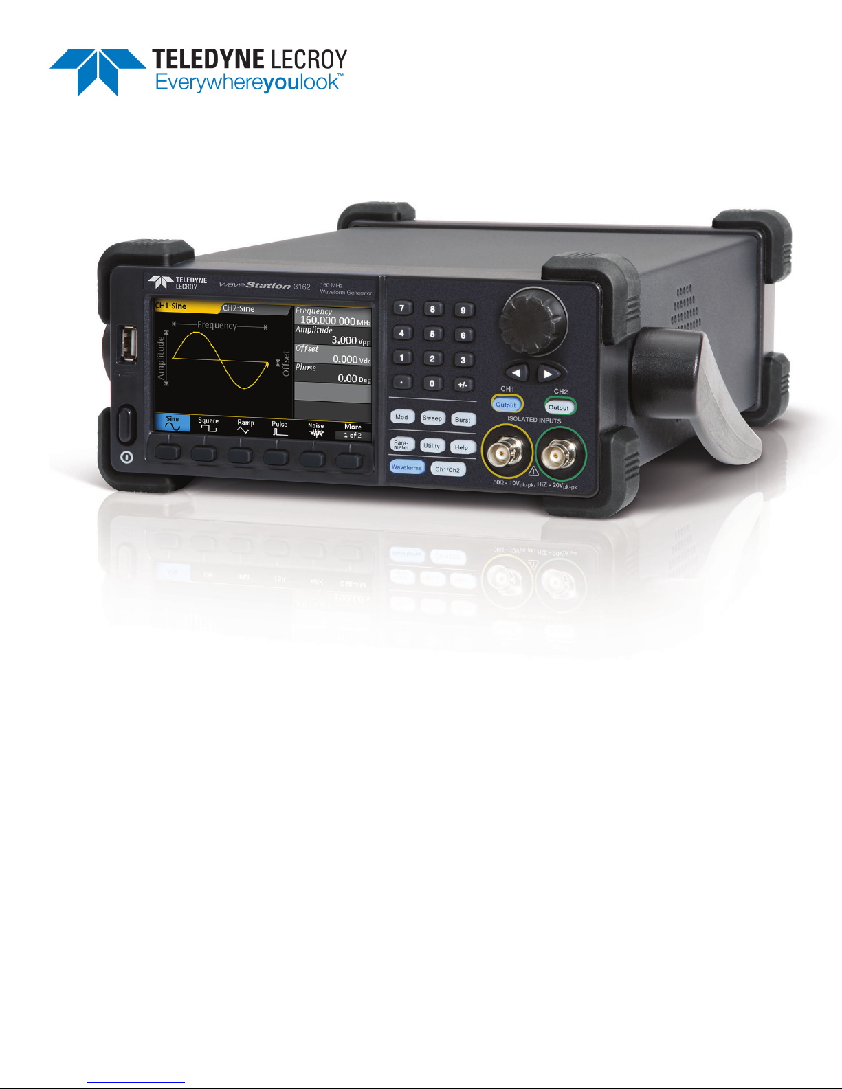
Thank you for purchasing a LeCroy WaveStation 3000 Series Function and Arbitrary Waveform Generator.
We’re certain you’ll be pleased with the detailed features so unique to our instruments.
This manual documents how to use the following WaveStation models:
l WaveStation 3082 80 MHz
l WaveStation 3122 120 MHz
l WaveStation 3162 160 MHz
The manual contains sections addressing:
l Product overview and safety information
l Working with WaveStation
l Generating basic, arbitrary, modulated, sweep, and burst waveforms
l Remote control
l Using WaveStation PC Software
l Changing system settings and other maintenance
l Reference, including product certifications and Teledyne LeCroy contact information
WaveStation can be controlled remotely by an automation device or by a person using the WaveStation PC
Software. The information in this manual is supplemented by a SCPI (Standard Commands for Programmable
Instruments) Command Reference Manual available at teledynelecroy.com.
Additional supplemental information in the form of Application Notes and LabBriefs are also available from our
website.
We truly hope you enjoy using Teledyne LeCroy's fine products.
Sincerely,
David C. Graef
Teledyne LeCroy
Vice President and Chief Technology Officer
922869 Rev B
iii

WaveStation 3000 Function and Arbitrary Waveform Generator
iv
922869 Rev B

Operator's Manual
Introduction to WaveStation
With five basic signal types and over 30 built-in arbitrary waveforms, the WaveStation is a versatile waveform
generator. A variety of modulation schemes, large color display, simple user interface, and remote control
capabilities make it easy to generate waveforms up to160 MHz.
High Performance and Signal Fidelity
High performance hardware enables WaveStation to create accurate, stable waveforms. High sample rate and
resolution combined with low jitter and harmonic distortion means the waveforms seen on the display match
the waveforms output by the hardware.
Graphical Waveform Creation
Use WaveStation PC Software to easily create and edit waveforms on your computer using mathematical
operations, filters and point-by-point editing—or draw a waveform with a mouse. Transfer waveforms from the
PC to WaveStation over USB, then view them on the large display. Connect a WaveAce® oscilloscope to the
same PC to enable seamless transfer of captured signals from the oscilloscope to the WaveStation.
Key Specifications
Bandwidth 80 MHz – 160 MHz
Channels
Memory 512 kpts
Sample Rate 500 MS/s
Vertical Resolution 14 bits
2
Detailed specifications are maintained on the product page at:
teledynelecroy.com/wavestation.
922869 Rev B
1

WaveStation 3000 Function and Arbitrary Waveform Generator
Package Contents
When your WaveStation is delivered, verify that all items on the packing list or invoice copy have shipped
correctly. Contact your nearest Teledyne LeCroy customer service center or national distributor if anything is
missing or damaged. We can only be responsible for replacement if you contact us immediately.
The standard WaveStation 3000 package includes the following:
l WaveStation unit
l Power Cord
l Standard USB 2.0 Type A to Type B Cable, 1 m
l USB-GPIB Converter Cable
l WaveStation 3000 Getting Started Guide
l Performance/Calibration Certificate
l Product Registration Card
2
922869 Rev B
Front Panel
Operator's Manual
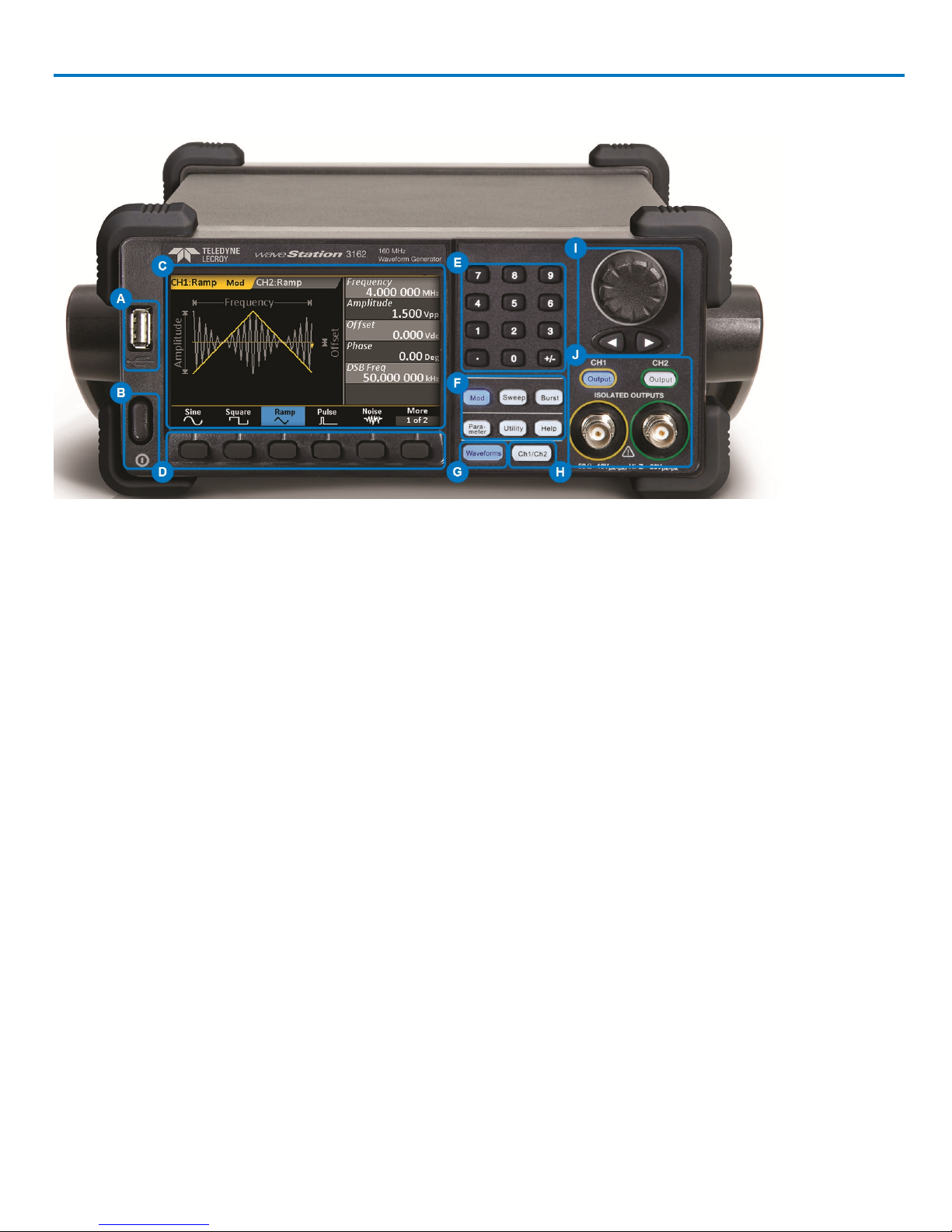
A. USB A Connector enables you to attach a storage drive.
B. Power Button turns on/off the WaveStation.
C. LCD Display shows an annotated waveform shape, the Parameter Value List, and the various option
menus.
D. Softkey Buttons enable you to select the corresponding option from the changing menus.
E. Numeric Keypad allows you to adjust parameter values and change units.
F. Function Buttons open corresponding option menus. The top, three Signal Conditioning buttons apply
Modulation, Sweep, or Burst to the active waveform. Parameter, Utility, and Help open their respective
menus.
G. Waveform Button opens the menu of waveform shapes.
H. Ch1/Ch2 Button selects the output channel and activates the corresponding tab on the display.
I. Adjustment Knob and Left/Right Cursor Buttonshelp with making selections and modifying values.
J. Output Buttons control the activation/deactivation of corresponding BNC Channel Outputs.
922869 Rev B
3
WaveStation 3000 Function and Arbitrary Waveform Generator
Back Panel
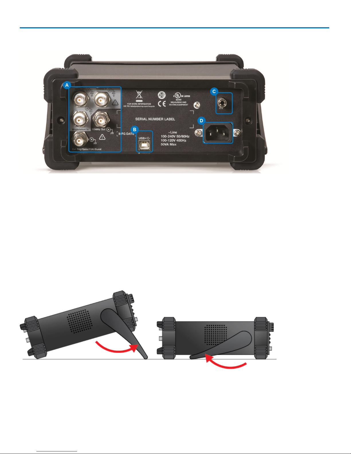
A. Input and Output BNC Connectors - provide 10 MHz In, 10 MHz Out,Modulation In, Synch Out, Ext
Trig/Gate/Fsk/Burst Out.
B. USB Connector - USB 2.0 Type B, used for making USBRAW or USBTMC connections.
C. Ground Connector
D. AC Power Connector
Adjusting the Viewing Position
The built-in carrying handle can be used to support the weight of the product and adjust the viewing position.
Gently pull both arms away from the sides of the WaveStation to unlock the mechanism, then rotate the
entire handle toward you until it snaps into the upright position.
4
922869 Rev B

Operator's Manual
Safety
Observe these instructions to keep the oscilloscope operating in a correct and safe condition. You are
required to follow generally accepted safety procedures in addition to the precautions listed here. The overall
safety of any system incorporating this instrument is the responsibility of the assembler of the system.
Symbols
These symbols may appear on the instrument's front or rear panels and in its documentation to alert you to
important safety considerations.
CAUTION of potential damage to instrument, or WARNING of potential bodily injury. Do not proceed until the information
is fully understood and conditions are met.
High voltage. Risk of electric shock or burn.
Measurement ground connection.
Safety (protective) ground connection.
Frame or chassis connection.
Power On/Off (front of instrument)
Precautions
Use proper power cord. Use only the power cord shipped with this instrument and certified for the country of
use.
Maintain ground. This product is grounded through the power cord grounding conductor. To avoid electric
shock, connect only to a grounded mating outlet.
Connect and disconnect properly. Do not connect/disconnect probes or test leads while they are connected to
a voltage source.
Observe all terminal ratings. Do not apply a voltage to any input (C1, C2, C3, C4 or EXT) that exceeds the
maximum rating of that input. Refer to the front of the oscilloscope for maximum input ratings.
Use only within operational environment listed. Do not use in wet or explosive atmospheres.
Use indoors only.
Keep product surfaces clean and dry. See Cleaning in the Maintenance section.
Do not block the cooling vents. Leave a minimum six-inch (15 cm) gap between the instrument and the
nearest object. Keep the underside clear of papers and other objects.
Do not remove the covers or inside parts. Refer all maintenance to qualified service personnel.
Do not operate with suspected failures. Do not use the product if any part is damaged. Obviously incorrect
measurement behaviors (such as failure to calibrate) might indicate impairment due to hazardous live
electrical quantities. Cease operation immediately and sequester the instrument from inadvertent use.
Operating Environment
Temperature: 0 to 40° C.
922869 Rev B
5

WaveStation 3000 Function and Arbitrary Waveform Generator
Humidity: Maximum relative humidity 80% for temperatures up to 31° C, decreasing linearly to 50% relative
humidity at 40° C.
Altitude: Up to 3,048 m (10,000 ft) at or below 30° C.
Cooling
The analyzer relies on forced air cooling with internal fans and vents. Take care to avoid restricting the
airflow to any part. Around the sides and rear, leave a minimum of 15 cm (6 inches) between the instruments
and the nearest object.The feet provide adequate bottom clearance.
CAUTION.Do not block cooling vents. Always keep the area beneath the instruments clear of paper
and other items.
The instruments also have internal fan control circuitry that regulates the fan speed based on the ambient
temperature. This is performed automatically after start-up.
Calibration
The recommended factory calibration interval is one year. Calibration should be performed by qualified
personnel only.
Extended warranty, calibration, and upgrade plans are available for purchase. To purchase a service plan,
contact your Teledyne LeCroy sales representative or:
cutomersupport@teledynelecroy.com
Power
AC POWER
The instrument operates from a single-phase, 100 to 240 Vrms (± 10%) AC power source at 50/60 Hz (± 10%)
and 100 to 120 Vrms (± 10%) AC power source at 400 Hz (± 5%). Manual voltage selection is not required
because the instrument automatically adapts to the line voltage.
POWER CONSUMPTION
50 VA (50 W) maximum power consumption when operating with all accessories installed.
GROUND
The AC inlet ground is connected directly to the frame of the instrument. For adequate protection again
electric shock, connect to a mating outlet with a safety ground contact.
WARNING. Only use the power cord provided with your instrument. Interrupting the protective
conductor inside or outside the oscilloscope, or disconnecting the safety ground terminal, creates a
hazardous situation. Intentional interruption is prohibited.
APPLYING POWER
The Power button on the front of the WaveStation controls the operational state of the instrument. Press the
button to switch the instrument AC power On or Off. Always use the Power button to execute a proper shut
down process and preserve settings before powering down. Do not power off by pulling the power cord from
the socket or shutting down a connected power strip.
6
922869 Rev B
Operator's Manual
Working with WaveStation
Function Buttons
These Front Panel buttons control major functional areas of the software.
They appear white when inactive, unlike the navigation and selection
controls, which are black.
Function buttons are lit blue when they are active. You can perform a Self
Test to check that the LED is working properly.
Channel and Waveform Buttons
The Ch1/Ch2 button is the starting point in waveform configuration. Press it to select the output channel and
activate the corresponding tab on the display.
The Waveform button opens the menu of basic and arbitrary waveform shapes. Whatever you select is
immediately assigned to the active channel.
Signal Conditioning Buttons
The top three function buttons are waveform signal conditioning buttons and apply Modulation, Sweep, or
Burst functions to the active waveform.
The first press of a Signal Conditioning button applies that functionality to the active waveform and opens a
menu of corresponding parameters. You'll see the name (e.g., "Mod" for Modulation) appear next to the carrier
waveform on the Channel tab. The second press removes the functionality from the waveform and closes the
menu.
Other Function Buttons
The next three function buttons, Parameter, Utility, and Help, open menus of functionality other than waveform
configuration.
l Parameter restores the menu of waveform parameters to the display for quick re-adjusting. This can be
useful if you've moved onto one of the other functional menus.
l Many output and system settings can be made through Utilities; see the topics in that section of this
manual.
l Help opens a menu of Help topics.
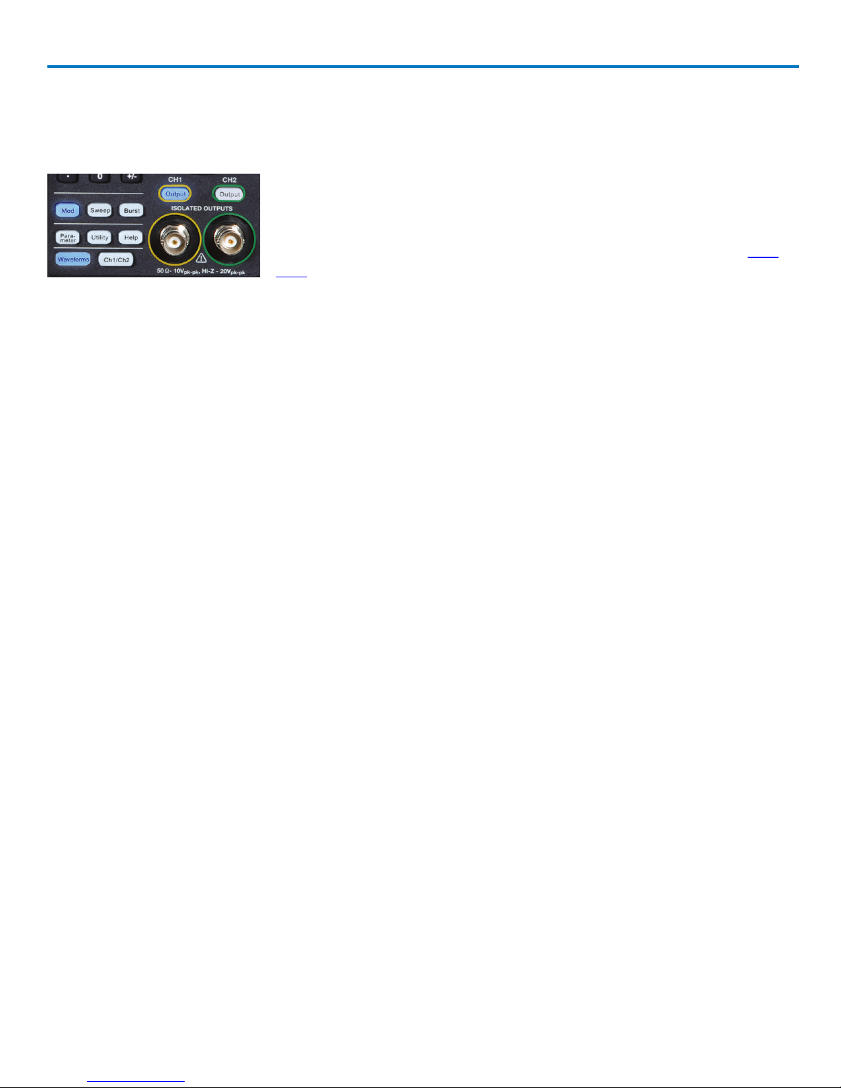
Output Buttons
These buttons, both labeled Output, each correspond to one of the output channels. They enable and disable
output on that channel. Connect a BNC cable to the output before activating the button.
922869 Rev B
7
WaveStation 3000 Function and Arbitrary Waveform Generator
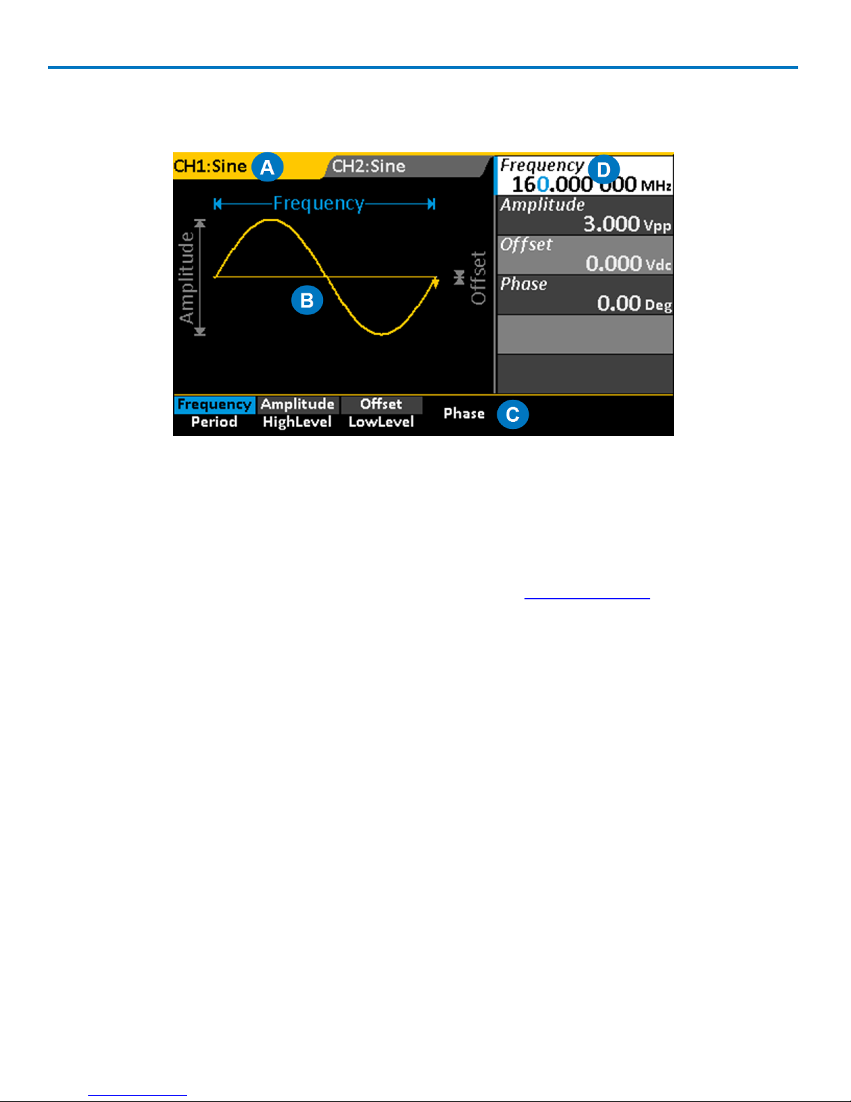
Understanding the Display
Each area of the display serves a unique function.
A. Channel Tabs display the currently selected waveform, plus any additional signal conditioning, such as
Modulation. The tab changes to match the channel color when it is active.
B. Waveform Display shows an annotated diagram of the waveform. The diagram shows how the selected
parameters relate to the wave shape.
C. Option Menu changes based on the chosen Waveform and Function.
D. Parameter Value List shows parameter settings. Use this area to adjust parameters.
Navigating Menus and Making Selections
Pressing any Function button opens a corresponding menu of options on the display. These menus are
navigated using the softkey buttons below them.
Option Menus and Softkey Buttons
The softkey buttons correlate with the menu options directly above them, which change based on
functionality. The softkeys behave a bit differently depending on the option. They may:
l Select a numeric parameter for editing on the Parameter Value List
l Toggle a set of non-numeric selections
l Open a second menu, etc.
Continue pressing the softkey button until your desired selection is highlighted in blue. Then, either adjust
the value on the Parameter List, or press the softkey for the next menu option you wish to select.
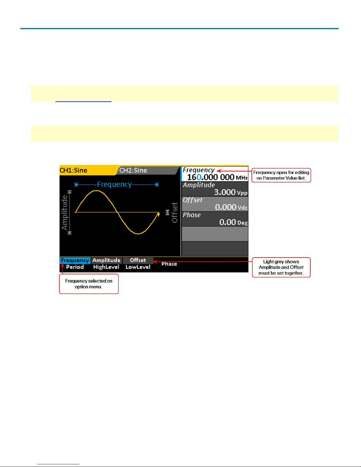
DUAL PARAMETER OPTIONS
A good portion of the menu options show two separate parameters.This indicates an either/or selection: you
can choose to configure one parameter or the other, but not both. For example, you can configure either
8
922869 Rev B
Operator's Manual
Frequency or Period, but not both.The first press of the softkey button selects the top parameter, which is then
highlighted in blue; the second press selects the bottom.
These dual parameter options have two different colored backgrounds, one lighter and one darker, to keep
them distinct. Selected parameters will show the lighter shading (when they are not active and blue), and
you'll notice that these are the parameters you see in the Parameter Value List. You may sometimes notice
that when you select one dual parameter, the shading changes over other dual parameters. This indicates
parameters that must be configured together. For example, Amplitude and Offset, or HighLevel and LowLevel.
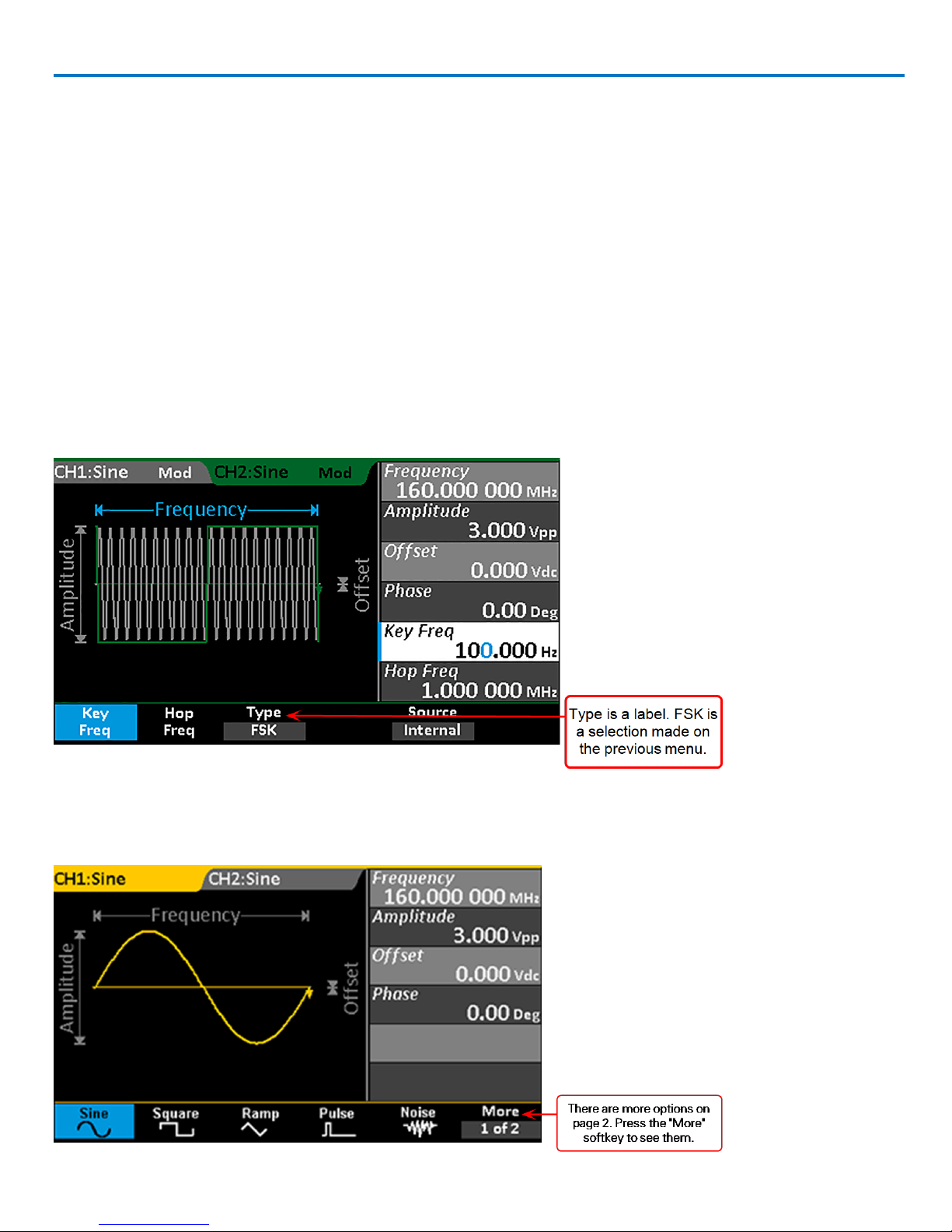
LABELED MENU OPTIONS
Some menu options appear to be dual parameters, but actually the top part of the option is a label, while the
bottom shows the selected value. When configuring waveforms, this usually indicates the selection was made
on a previous menu, but is made available again in case you decide to change it. For example, when you
display Modulation parameters, the Type option shows the selection made on the previous Modulation type
menu. You need only press the softkey for these menu options if you now wish to change the selection.
ADDITIONAL MENUS
Menus that have a More at the end have additional pages of options. Press the softkey button to go to the next
or previous page.
922869 Rev B
9

WaveStation 3000 Function and Arbitrary Waveform Generator
DONE AND CANCEL
Some option menus, such as Utilities, go several levels deep. In this case, you may see a Done or Cancel
option at the end of the menu. The procedures in this manual explain their use in specific situations, which
may vary slightly menu to menu.
Parameter Value List
The right side of the display is a detailed list of numeric parameter values. This area is used to adjust the
parameter.
Adjusting Parameters
Once a numeric parameter has been selected from an option menu, it is activated for editing on the
Parameter Value list. You can adjust the value using either the front panel Adjustment knob or the numeric
keypad.
Using the Adjustment Knob
This is perhaps the easiest way to both select and adjust parameters when configuring waveforms.
1. Select the first parameter from the menu using the softkey button.The parameter will appear blue on the
option menu and white on the Parameter Value list.
2. Use the Left/Right Cursor buttons to select the digit to change. The selected digit is highlighted blue.
3. Turn the Adjustment knob to raise or lower the value of the digit.
4. Repeat Steps 2 and 3 until all digits are adjusted.
5. Press the Adjustment knob to save the setting and activate the next parameter on the list.
The Adjustment knob is also used to navigate and select from the Built-in Arbitrary waveform menus. In
general, if a selection is highlighted white on the display, it can be controlled using the Adjustment knob.
10
922869 Rev B
Operator's Manual
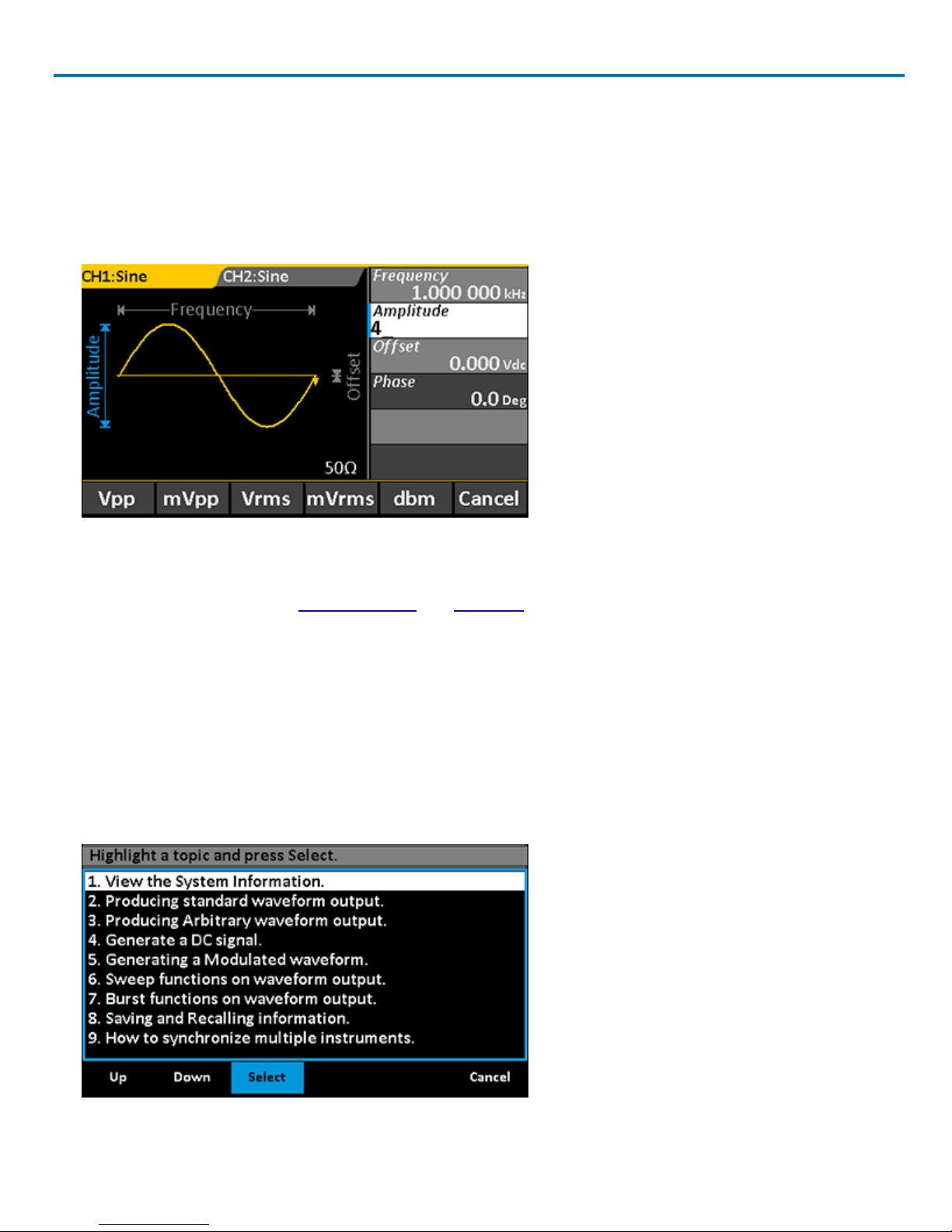
Using the Keypad
This method is required to change the unit of measure associated with the parameter value.
1. Select the parameter from the option menu using the softkey button. The parameter will appear blue on
the Parameter menu and white on the Parameter Value list.
2. Press the keypad buttons to enter the new value. The display will change to show a menu of unit s of measure.
3. If desired, press the softkey to select a new unit of measure.You will return to the parameter menu.
4. Use the softkeys to select the next parameter to edit.
The Keypad is also used during Self Calibration and Self Test functions.
Using WaveStation Help
Onboard Help provides brief topics to guide you while using the system. To use the Help:
1. Press the Help function button on the Front Panel to open the Help menu. A list of topics appears on the
display.
2. Press the Up or Down softkey buttons to navigate the list.
3. When the desired topic is highlighted on the display, press the Select softkey to view it.
4. Press Done to return to the menu of Help topics, or Cancel to exit the Help menu.
922869 Rev B
11
WaveStation 3000 Function and Arbitrary Waveform Generator
Generating Basic Waveforms
Follow this procedure to generate one of the five basic waveform types.
1. Choose your output channel by pressing the Ch1/Ch2function button until the correct tab is active on the
display.
NOTE: WaveStation defaults to the Channel 1 tab and Waveform menu whenever you power on, although
you can change this setting on the Utility menu. If Channel 1 is correct, skip to Step 2.
2. Press the Waveform function button to open the Waveform menu, then select the desired shape using the
softkey.The options are: Sine, Square, Ramp, Pulse, and Noise.
NOTE: The default and min/max settings for each waveform depend on your WaveStation model. See the
specifications maintained on the product datasheet at teledynelecroy.com.
You should see your waveform selection appear on the active Channel tab, along with the parameter
option menu and Parameter Value list.
12
922869 Rev B
 Loading...