

Teledyne 2105, ISCO 2105, ISCO 2105Gi, ISCO 2105Ci Installation And Operation Manual
2105/2105Ci/Gi
Part #69-2003-635 of Assembly #60-2004-635
Copyright © 2011. All rights reserved, Teledyne Instruments, Inc.
Revision C, August 2013
Interface Module
Installation and Operation Guide


Foreword
This instruction manual is designed to help you gain a thorough understanding of the operation of
the equipment. Teledyne Isco recommends that you read this manual completely before placing the
equipment in service.
Although Teledyne Isco designs reliability into all equipment, there is always the possibility of a
malfunction. This manual may help in diagnosing and repairing the malfunction.
If a problem persists, call or e-mail the Teledyne Isco Technical Service Department for assistance.
Simple difficulties can often be diagnosed over the phone.
If it is necessary to return the equipment to the factory for service, please follow the shipping
instructions provided by the Customer Service Department, including the use of the Return
Authorization Number specified. Be sure to include a note describing the malfunction. This
will aid in the prompt repair and return of the equipment.
Teledyne Isco welcomes suggestions that would improve the information presented in this manual
or enhance the operation of the equipment itself.
Teledyne Isco is continually improving its products and reserves the right to change product
specifications, replacement parts, schematics, and instructions without notice.
Contact Information
Customer Service
Phone: (800) 228-4373 (USA, Canada, Mexico)
Fax: (402) 465-3022
Email: IscoCSR@teledyne.com
Technical Support
Phone: Toll Free (866) 298-6174 (Samplers and Flow Meters)
Email: IscoService@teledyne.com
Return equipment to: 4700 Superior Street, Lincoln, NE 68504-1398
Other Correspondence
Mail to: P.O. Box 82531, Lincoln, NE 68501-2531
Email: IscoInfo@teledyne.com
(402) 464-0231 (Outside North America)
Toll Free (800) 775-2965 (Syringe Pumps and Liquid Chromatography)
Revised September 2012

2105 Interface Module
WARNING
AVERTISSEMENT
CAUTION
WARNING
DANGER
Safety
2105 Interface Module
Safety
General Warnings Before installing, operating, or maintaining this equipment, it is
imperative that all hazards and preventive measures are fully
understood. While specific hazards may vary according to
location and application, take heed of the following general
warnings:
Avoid hazardous practices! If you use this instrument in
any way not specified in this manual, the protection
provided by the instrument may be impaired.
Éviter les usages périlleux! Si vous utilisez cet instrument
d’une manière autre que celles qui sont specifiées dans ce
manuel, la protection fournie de l’instrument peut être
affaiblie; cela augmentera votre risque de blessure.
Hazard Severity Levels This manual applies Hazard Severity Levels to the safety alerts,
These three levels are described in the sample alerts below.
Cautions identify a potential hazard, which if not avoided, may
result in minor or moderate injury. This category can also warn
you of unsafe practices, or conditions that may cause property
damage.
Warnings identify a potentially hazardous condition, which
if not avoided, could result in death or serious injury.
DANGER – limited to the most extreme situations
to identify an imminent hazard, which if not
avoided, will result in death or serious injury.
iii
2105 Interface Module
Safety
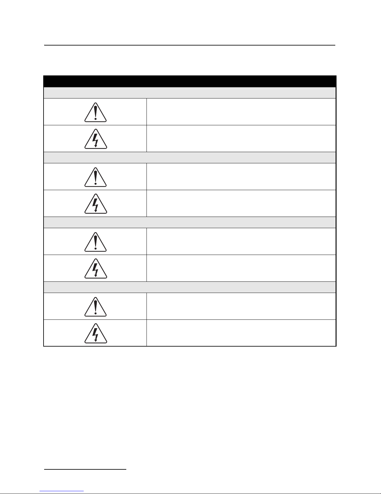
Hazard Symbols The equipment and this manual use symbols used to warn of
hazards. The symbols are explained below.
Hazard Symbols
Warnings and Cautions
The exclamation point within the triangle is a warning sign alerting you of
important instructions in the instrument’s technical reference manual.
The lightning flash and arrowhead within the triangle is a warning sign alerting you of “dangerous voltage” inside the product.
Symboles de sécurité
Ce symbole signale l’existence d’instructions importantes relatives au
produit dans ce manuel.
Ce symbole signale la présence d’un danger d’électocution.
Warnungen und Vorsichtshinweise
Advertencias y Precauciones
Das Ausrufezeichen in Dreieck ist ein Warnzeichen, das Sie darauf
aufmerksam macht, daß wichtige Anleitungen zu diesem Handbuch
gehören.
Der gepfeilte Blitz im Dreieck ist ein Warnzeichen, das Sei vor “gefährlichen
Spannungen” im Inneren des Produkts warnt.
Esta señal le advierte sobre la importancia de las instrucciones del manual
que acompañan a este producto.
Esta señal alerta sobre la presencia de alto voltaje en el interior del
producto.
iv

2105 Interface Module
Table of Contents
Section 1 Introduction
1.1 Product Description. . . . . . . . . . . . . . . . . . . . . . . . . . . . . . . . . . . . . . . . . . . . . . . . . . 1-1
1.2 2105 Module Components. . . . . . . . . . . . . . . . . . . . . . . . . . . . . . . . . . . . . . . . . . . . . 1-2
1.3 Battery Module Components . . . . . . . . . . . . . . . . . . . . . . . . . . . . . . . . . . . . . . . . . . 1-4
1.4 Technical Specifications . . . . . . . . . . . . . . . . . . . . . . . . . . . . . . . . . . . . . . . . . . . . . . 1-6
1.5 Safety Symbols and Hazard Alerts . . . . . . . . . . . . . . . . . . . . . . . . . . . . . . . . . . . . . 1-9
1.6 Technical Service. . . . . . . . . . . . . . . . . . . . . . . . . . . . . . . . . . . . . . . . . . . . . . . . . . . 1-10
Section 2 Installation and Operation
2.1 Unpacking Instructions . . . . . . . . . . . . . . . . . . . . . . . . . . . . . . . . . . . . . . . . . . . . . . 2-1
2.2 System Power . . . . . . . . . . . . . . . . . . . . . . . . . . . . . . . . . . . . . . . . . . . . . . . . . . . . . . 2-1
2.3 Installation Preparation . . . . . . . . . . . . . . . . . . . . . . . . . . . . . . . . . . . . . . . . . . . . . . 2-3
2.3.1 Latches - Locking and Unlocking . . . . . . . . . . . . . . . . . . . . . . . . . . . . . . . . . 2-4
2.3.2 Communication Connectors . . . . . . . . . . . . . . . . . . . . . . . . . . . . . . . . . . . . . 2-5
2.3.3 Installing the Batteries . . . . . . . . . . . . . . . . . . . . . . . . . . . . . . . . . . . . . . . . . 2-6
2.4 Stacking Modules . . . . . . . . . . . . . . . . . . . . . . . . . . . . . . . . . . . . . . . . . . . . . . . . . . . 2-7
2.5 Connecting to Flowlink. . . . . . . . . . . . . . . . . . . . . . . . . . . . . . . . . . . . . . . . . . . . . . . 2-8
2.5.1 Modem Site Connection . . . . . . . . . . . . . . . . . . . . . . . . . . . . . . . . . . . . . . . . 2-12
2.6 Power Conservation (cellular modules) . . . . . . . . . . . . . . . . . . . . . . . . . . . . . . . . . 2-14
2.7 Setting Up Text Alarms (cellular modules) . . . . . . . . . . . . . . . . . . . . . . . . . . . . . . 2-15
2.8 Pushed Data Capability
(cellular modules) . . . . . . . . . . . . . . . . . . . . . . . . . . . . . . . . . . . . . . . . . . . . . . . . . . 2-17
2.9 SDI-12 Input . . . . . . . . . . . . . . . . . . . . . . . . . . . . . . . . . . . . . . . . . . . . . . . . . . . . . . 2-18
2.10 Rain Gauge Interface . . . . . . . . . . . . . . . . . . . . . . . . . . . . . . . . . . . . . . . . . . . . . . 2-19
2.11 Sampler Interface . . . . . . . . . . . . . . . . . . . . . . . . . . . . . . . . . . . . . . . . . . . . . . . . . 2-20
2.12 Sampler Pass-Through Mode . . . . . . . . . . . . . . . . . . . . . . . . . . . . . . . . . . . . . . . . 2-21
2.13 Pulse Doppler Devices. . . . . . . . . . . . . . . . . . . . . . . . . . . . . . . . . . . . . . . . . . . . . . 2-25
2.14 Modbus Input . . . . . . . . . . . . . . . . . . . . . . . . . . . . . . . . . . . . . . . . . . . . . . . . . . . . 2-26
2.14.1 4200 and 6700 Series Measured Data . . . . . . . . . . . . . . . . . . . . . . . . . . . 2-28
2.15 Cables. . . . . . . . . . . . . . . . . . . . . . . . . . . . . . . . . . . . . . . . . . . . . . . . . . . . . . . . . . . 2-34
2.16 2105 Universal Cable . . . . . . . . . . . . . . . . . . . . . . . . . . . . . . . . . . . . . . . . . . . . . . 2-35
2.16.1 Preparation . . . . . . . . . . . . . . . . . . . . . . . . . . . . . . . . . . . . . . . . . . . . . . . . 2-35
2.16.2 2105 Connection . . . . . . . . . . . . . . . . . . . . . . . . . . . . . . . . . . . . . . . . . . . . . 2-35
Section 3 2105Ci Cellular Modem Module
3.1 Overview . . . . . . . . . . . . . . . . . . . . . . . . . . . . . . . . . . . . . . . . . . . . . . . . . . . . . . . . . . 3-1
3.1.1 Data Retrieval . . . . . . . . . . . . . . . . . . . . . . . . . . . . . . . . . . . . . . . . . . . . . . . . 3-1
3.1.2 Text Messaging . . . . . . . . . . . . . . . . . . . . . . . . . . . . . . . . . . . . . . . . . . . . . . . 3-1
3.1.3 Stacking / Compatibility . . . . . . . . . . . . . . . . . . . . . . . . . . . . . . . . . . . . . . . . 3-1
3.1.4 Cellular Service . . . . . . . . . . . . . . . . . . . . . . . . . . . . . . . . . . . . . . . . . . . . . . . 3-1
3.1.5 2105Ci Label Information . . . . . . . . . . . . . . . . . . . . . . . . . . . . . . . . . . . . . . . 3-2
3.2 Magnetic-Mount Antenna. . . . . . . . . . . . . . . . . . . . . . . . . . . . . . . . . . . . . . . . . . . . . 3-2
Section 4 2105Gi Cellular Modem Module
4.1 Overview . . . . . . . . . . . . . . . . . . . . . . . . . . . . . . . . . . . . . . . . . . . . . . . . . . . . . . . . . . 4-1
v

2105 Interface Module
Table of Contents
Section 5 Modbus Protocol and 2100 Output
Section 6 Maintenance
4.1.1 Data Retrieval . . . . . . . . . . . . . . . . . . . . . . . . . . . . . . . . . . . . . . . . . . . . . . . . 4-1
4.1.2 Text Messaging . . . . . . . . . . . . . . . . . . . . . . . . . . . . . . . . . . . . . . . . . . . . . . . 4-1
4.1.3 Stacking / Compatibility . . . . . . . . . . . . . . . . . . . . . . . . . . . . . . . . . . . . . . . . 4-1
4.2 SIM Card . . . . . . . . . . . . . . . . . . . . . . . . . . . . . . . . . . . . . . . . . . . . . . . . . . . . . . . . . . 4-1
4.3 Antenna Options . . . . . . . . . . . . . . . . . . . . . . . . . . . . . . . . . . . . . . . . . . . . . . . . . . . . 4-4
4.3.1 Magnetic-Mount Antenna . . . . . . . . . . . . . . . . . . . . . . . . . . . . . . . . . . . . . . . 4-4
4.3.2 In-Street Antenna . . . . . . . . . . . . . . . . . . . . . . . . . . . . . . . . . . . . . . . . . . . . . 4-4
4.3.3 Manhole Lid-Mount Antenna . . . . . . . . . . . . . . . . . . . . . . . . . . . . . . . . . . . . 4-5
5.1 Introduction. . . . . . . . . . . . . . . . . . . . . . . . . . . . . . . . . . . . . . . . . . . . . . . . . . . . . . . . 5-1
5.2 Operation . . . . . . . . . . . . . . . . . . . . . . . . . . . . . . . . . . . . . . . . . . . . . . . . . . . . . . . . . . 5-1
5.2.1 Establishing Communication . . . . . . . . . . . . . . . . . . . . . . . . . . . . . . . . . . . . 5-2
5.2.2 Module Addressing . . . . . . . . . . . . . . . . . . . . . . . . . . . . . . . . . . . . . . . . . . . . 5-2
5.3 Configurations. . . . . . . . . . . . . . . . . . . . . . . . . . . . . . . . . . . . . . . . . . . . . . . . . . . . . . 5-3
5.4 Glossary of Terms . . . . . . . . . . . . . . . . . . . . . . . . . . . . . . . . . . . . . . . . . . . . . . . . . . . 5-4
5.5 Common Acronyms . . . . . . . . . . . . . . . . . . . . . . . . . . . . . . . . . . . . . . . . . . . . . . . . . . 5-5
5.6 Register Specifications - 2100 Output . . . . . . . . . . . . . . . . . . . . . . . . . . . . . . . . . . . 5-5
5.6.1 Register Addresses . . . . . . . . . . . . . . . . . . . . . . . . . . . . . . . . . . . . . . . . . . . . . 5-6
6.1 Overview . . . . . . . . . . . . . . . . . . . . . . . . . . . . . . . . . . . . . . . . . . . . . . . . . . . . . . . . . . 6-1
6.1.1 Cleaning . . . . . . . . . . . . . . . . . . . . . . . . . . . . . . . . . . . . . . . . . . . . . . . . . . . . . 6-1
6.2 Desiccant . . . . . . . . . . . . . . . . . . . . . . . . . . . . . . . . . . . . . . . . . . . . . . . . . . . . . . . . . . 6-1
6.2.1 Replacing the Desiccant . . . . . . . . . . . . . . . . . . . . . . . . . . . . . . . . . . . . . . . . 6-2
6.2.2 Reactivating the Desiccant . . . . . . . . . . . . . . . . . . . . . . . . . . . . . . . . . . . . . . 6-2
6.3 Hydrophobic Filter . . . . . . . . . . . . . . . . . . . . . . . . . . . . . . . . . . . . . . . . . . . . . . . . . . 6-3
6.4 O-Rings . . . . . . . . . . . . . . . . . . . . . . . . . . . . . . . . . . . . . . . . . . . . . . . . . . . . . . . . . . . 6-3
6.5 How to Obtain Service . . . . . . . . . . . . . . . . . . . . . . . . . . . . . . . . . . . . . . . . . . . . . . . 6-3
Appendix A Replacement Parts List
A.1 Replacement Parts Diagrams and Listings . . . . . . . . . . . . . . . . . . . . . . . . . . . . . . A-1
A.2 2105/Ci/Gi Module . . . . . . . . . . . . . . . . . . . . . . . . . . . . . . . . . . . . . . . . . . . . . . . . . . A-2
A.3 2105 Ci Magnetic Mount Antenna. . . . . . . . . . . . . . . . . . . . . . . . . . . . . . . . . . . . . . A-8
A.4 2105Gi Magnetic Mount Antenna . . . . . . . . . . . . . . . . . . . . . . . . . . . . . . . . . . . . . A-10
A.5 2105Ci/Gi In-Street Antenna. . . . . . . . . . . . . . . . . . . . . . . . . . . . . . . . . . . . . . . . . A-12
A.6 2191 Battery Module . . . . . . . . . . . . . . . . . . . . . . . . . . . . . . . . . . . . . . . . . . . . . . . A-14
Appendix B Accessories
B.1 How to Order. . . . . . . . . . . . . . . . . . . . . . . . . . . . . . . . . . . . . . . . . . . . . . . . . . . . . . . B-1
B.2 General Accessories . . . . . . . . . . . . . . . . . . . . . . . . . . . . . . . . . . . . . . . . . . . . . . . . . B-1
B.3 Cables . . . . . . . . . . . . . . . . . . . . . . . . . . . . . . . . . . . . . . . . . . . . . . . . . . . . . . . . . . . .B-2
Appendix C Material Safety Data Sheets
List of Figures
1-1 2105 Components - Top View . . . . . . . . . . . . . . . . . . . . . . . . . . . . . . . . . . . . . . . . . 1-2
1-2 2105 Components - Bottom View . . . . . . . . . . . . . . . . . . . . . . . . . . . . . . . . . . . . . . 1-3
1-3 Battery module components, top view . . . . . . . . . . . . . . . . . . . . . . . . . . . . . . . . . . 1-4
vi

2105 Interface Module
Table of Contents
1-4 Battery Module Components, Bottom View . . . . . . . . . . . . . . . . . . . . . . . . . . . . . . 1-5
1-5 Specification drawing: 2105 (larger width for cellular modules) . . . . . . . . . . . . . . 1-7
1-6 Specification drawing: 2105 mounted on 2191 battery module . . . . . . . . . . . . . . . 1-8
2-1 Identifying the 2150 voltage specification . . . . . . . . . . . . . . . . . . . . . . . . . . . . . . . 2-2
2-2 Identifying the voltage specification on the DB9 cable . . . . . . . . . . . . . . . . . . . . . 2-3
2-3 Unlocking the latch . . . . . . . . . . . . . . . . . . . . . . . . . . . . . . . . . . . . . . . . . . . . . . . . . 2-4
2-4 Locking the latch . . . . . . . . . . . . . . . . . . . . . . . . . . . . . . . . . . . . . . . . . . . . . . . . . . . 2-5
2-5 Loading the 2191 Battery module . . . . . . . . . . . . . . . . . . . . . . . . . . . . . . . . . . . . . . 2-6
2-6 Unlock latch and stow the cap . . . . . . . . . . . . . . . . . . . . . . . . . . . . . . . . . . . . . . . . . 2-7
2-7 Aligning the modules . . . . . . . . . . . . . . . . . . . . . . . . . . . . . . . . . . . . . . . . . . . . . . . . 2-7
2-8 Flowlink connect screen . . . . . . . . . . . . . . . . . . . . . . . . . . . . . . . . . . . . . . . . . . . . . . 2-8
2-9 Site resolution screen . . . . . . . . . . . . . . . . . . . . . . . . . . . . . . . . . . . . . . . . . . . . . . . . 2-9
2-10 Site Information screen . . . . . . . . . . . . . . . . . . . . . . . . . . . . . . . . . . . . . . . . . . . . 2-10
2-11 Devices screen - connected to site . . . . . . . . . . . . . . . . . . . . . . . . . . . . . . . . . . . . 2-11
2-12 Modem screen - configuring the cellular modem . . . . . . . . . . . . . . . . . . . . . . . . 2-12
2-13 Devices screen - configuring for Serial-Over-IP
communication (2105Ci shown) . . . . . . . . . . . . . . . . . . . . . . . . . . . . . . . . . . . . . . 2-13
2-14 Wireless power control window . . . . . . . . . . . . . . . . . . . . . . . . . . . . . . . . . . . . . . 2-14
2-15 Setting up text messaging and alarm conditions . . . . . . . . . . . . . . . . . . . . . . . . 2-15
2-16 Data tab . . . . . . . . . . . . . . . . . . . . . . . . . . . . . . . . . . . . . . . . . . . . . . . . . . . . . . . . 2-17
2-17 Sonde setup tab . . . . . . . . . . . . . . . . . . . . . . . . . . . . . . . . . . . . . . . . . . . . . . . . . . 2-18
2-18 Rainfall measurement tab . . . . . . . . . . . . . . . . . . . . . . . . . . . . . . . . . . . . . . . . . . 2-19
2-19 Sampler tab . . . . . . . . . . . . . . . . . . . . . . . . . . . . . . . . . . . . . . . . . . . . . . . . . . . . . 2-20
2-20 Data Storage Setup window . . . . . . . . . . . . . . . . . . . . . . . . . . . . . . . . . . . . . . . . 2-21
2-21 Cable connections for sampler Pass-Through Mode . . . . . . . . . . . . . . . . . . . . . . 2-22
2-22 HyperTerminal connection screen . . . . . . . . . . . . . . . . . . . . . . . . . . . . . . . . . . . . 2-22
2-23 Specifying the connection number . . . . . . . . . . . . . . . . . . . . . . . . . . . . . . . . . . . . 2-23
2-24 HyperTerminal Settings tab . . . . . . . . . . . . . . . . . . . . . . . . . . . . . . . . . . . . . . . . 2-23
2-25 HyperTerminal connect window . . . . . . . . . . . . . . . . . . . . . . . . . . . . . . . . . . . . . 2-24
2-26 ADFM tab for Pulse Doppler devices . . . . . . . . . . . . . . . . . . . . . . . . . . . . . . . . . 2-25
2-27 Modbus input tab . . . . . . . . . . . . . . . . . . . . . . . . . . . . . . . . . . . . . . . . . . . . . . . . . 2-26
2-28 Modbus configuration window . . . . . . . . . . . . . . . . . . . . . . . . . . . . . . . . . . . . . . . 2-27
2-29 Device parameters (measured data) . . . . . . . . . . . . . . . . . . . . . . . . . . . . . . . . . . 2-27
2-30 2105 cables and associated equipment . . . . . . . . . . . . . . . . . . . . . . . . . . . . . . . . 2-34
2-31 2105 Interface connector . . . . . . . . . . . . . . . . . . . . . . . . . . . . . . . . . . . . . . . . . . . 2-35
3-1 2103Ci module serial label . . . . . . . . . . . . . . . . . . . . . . . . . . . . . . . . . . . . . . . . . . . . 3-2
3-2 2105Ci magnetic mount antenna . . . . . . . . . . . . . . . . . . . . . . . . . . . . . . . . . . . . . . 3-2
4-1 Accessing the SIM card on the bottom of the module . . . . . . . . . . . . . . . . . . . . . . 4-2
4-2 SIM card slot and release switch (unlocked position) . . . . . . . . . . . . . . . . . . . . . . 4-2
4-3 Inserting the SIM card into the module . . . . . . . . . . . . . . . . . . . . . . . . . . . . . . . . . 4-3
4-4 2105Gi magnetic mount antenna . . . . . . . . . . . . . . . . . . . . . . . . . . . . . . . . . . . . . . 4-4
4-5 Buried-in-street antenna . . . . . . . . . . . . . . . . . . . . . . . . . . . . . . . . . . . . . . . . . . . . . 4-4
4-6 Manhole lid-mount antenna . . . . . . . . . . . . . . . . . . . . . . . . . . . . . . . . . . . . . . . . . . 4-5
4-7 Manhole lid-mount antenna: Installation . . . . . . . . . . . . . . . . . . . . . . . . . . . . . . . . 4-5
5-1 Configuration example (direct connection shown) . . . . . . . . . . . . . . . . . . . . . . . . . 5-3
List of Tables
1-1 2105 Interface Module Components - Top View . . . . . . . . . . . . . . . . . . . . . . . . . . . 1-2
1-2 2105 Interface Module Components - Bottom View . . . . . . . . . . . . . . . . . . . . . . . . 1-3
1-3 Battery Module Components - Top View . . . . . . . . . . . . . . . . . . . . . . . . . . . . . . . . 1-4
1-4 Battery Module Components - Bottom View . . . . . . . . . . . . . . . . . . . . . . . . . . . . . 1-5
1-5 Technical Specifications: 2105 Interface Module . . . . . . . . . . . . . . . . . . . . . . . . . . 1-6
1-6 Technical Specifications: 2191 Battery Module . . . . . . . . . . . . . . . . . . . . . . . . . . . 1-7
2-1 Voltage Specifications for 2100 System Components . . . . . . . . . . . . . . . . . . . . . . . 2-2
2-2 Sampler Pass Through Mode Connection Steps . . . . . . . . . . . . . . . . . . . . . . . . . 2-24
vii

2105 Interface Module
Table of Contents
2-3 4200/6700 Series Supported Data Types . . . . . . . . . . . . . . . . . . . . . . . . . . . . . . . 2-30
2-4 2105 Port Connector Functions . . . . . . . . . . . . . . . . . . . . . . . . . . . . . . . . . . . . . . . 2-36
viii

2105 Interface Module
Note
Section 1 Introduction
This instruction manual is designed to help you gain a thorough
understanding of the operation of the 2105, 2105Ci, and 2105Gi
Interface Modules. Teledyne Isco recommends that you read this
manual completely before placing the equipment into service.
Information in this manual pertains to both the 2105 module and
2105Ci/Gi cellular modem modules. Specific differences between
the modules are identified wherever they occur.
Part numbers for ordering associated equipment and accessories
can be found in Appendices A and B, near the end of this manual.
1.1 Product Description The 2105 Interface Module is designed to store data from Isco’s
2100 Series flow modules and Pulse Doppler flow meters. The
2105 also provides Modbus input, sampler interface, and rain
gauge and SDI-12 input. It works in conjunction with Isco’s
Flowlink software.
If you have ordered any version of the Isco Model 677 logging
rain gauge (Isco rain gauge and 2105 module combination),
your system includes the rain gauge interface cable.
The 2105 can be located anywhere within a stack of up to three
other 2100 Series networked modules, using the same locking
mechanism that connects the 2100 Series modules to each other.
The 2105 is compatible with Isco’s 2150 Area Velocity flow
module, 2110 Ultrasonic flow module, 2160 LaserFlow module,
2101 Field Wizard, 2103 landline modem module, 2103Ci cellular
modem module, and 2102 wireless module. The stack can be
powered by any of several power options offered by Teledyne Isco,
such as the 2191 battery module.
All enclosures are rated NEMA 4X, 6P (IP68). The permanently
sealed enclosures are designed to meet the environmental
demands of many flow monitoring applications. All connections
between modules, sensors, and communication cables lock in
place. The locking mechanisms strongly secure the components
and ensure a watertight seal.
1-1
2105 Interface Module
11
2
2
3
3
4
4
5
5
6
7
8
8
2105 Module
Cellular Modem Module
Section 1 Introduction
1.2 2105 Module
Components
Figures 1-1 and 1-2 identify the key components of the 2105
Interface Module.
Figure 1-1 2105 Components - Top View
Table 1-1 2105 Interface Module Components - Top View
Item No. Name Description
1 Communication Connector This port is used to connect the 2105 to other modules in a stack,
or to a computer using an RS232 cable.
2 Connector Cap Install on the communication connector when it is not in use to
protect the connector from moisture damage. When the connector
is in use, store the connector cap on the cap holder.
3 Cap Holder Stores the connector cap when the communication connector is in
use.
4 Instrument Interface
Cable Connector
5 Connector Plug Insert into the interface connector when the connector is not in
6 Antenna Cable Connector
(cellular modules)
7 Connector Plug
8 Latch Release Push in to unlock the module from a stack.
(cellular modules)
Used to connect the module to compatible equipment for data
logging and sampler control
use to protect it from damage.
Used to connect the modem to the magnetic mount antenna.
Insert into the antenna cable connector when the connector is not
in use to protect it from damage.
1-2
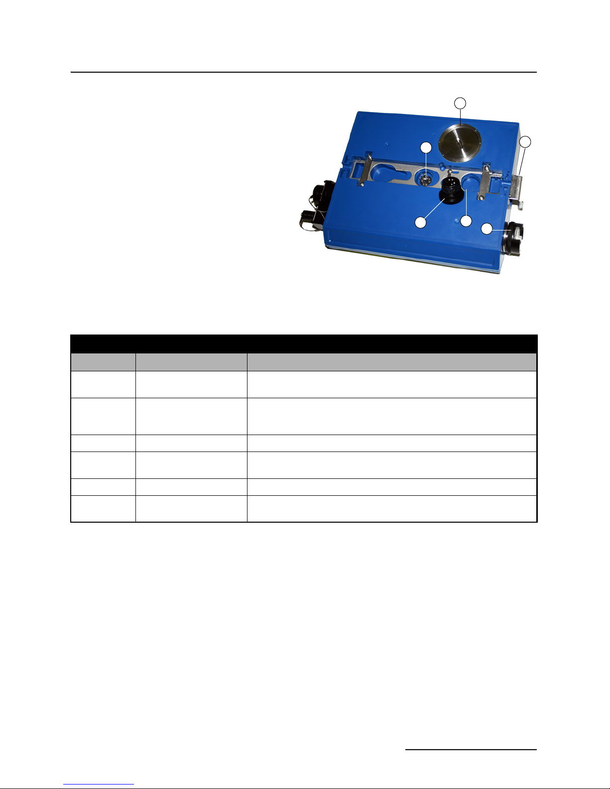
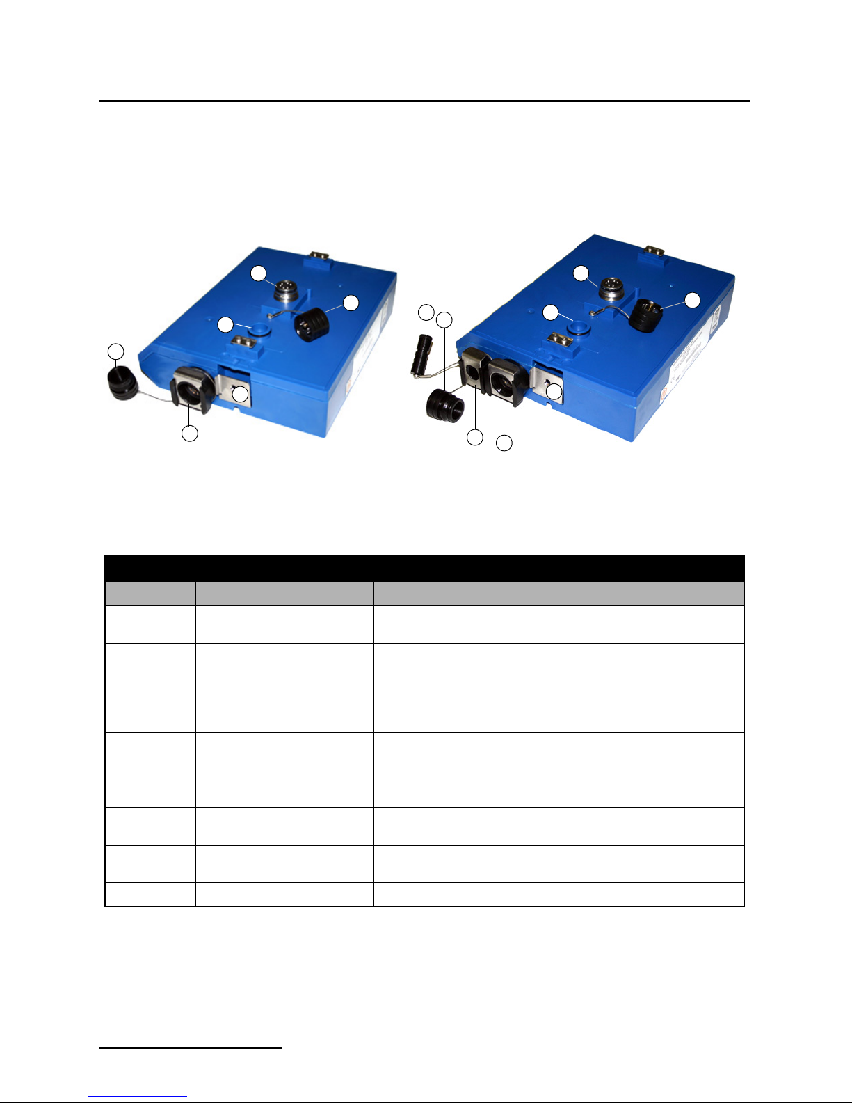
Figure 1-2 2105 Components - Bottom View
1
2
4
3
5
6
2105 Interface Module
Section 1 Introduction
Table 1-2 2105 Interface Module Components - Bottom View
Item No. Name Description
1 Communication and Power
Connector
2 Connector Plug Insert into the communication connector when not in use to protect the
3 Plug Holder Stores the connector Plug when the communication connector is in use.
4 Desiccant Cartridge and
Hydrophobic Filter
5 Latch Push in to lock the module in a stack.
6 SIM Card Compartment
Cover (2105Gi only)
This connects the 2105 to other 2100 Series modules in the stack and is
used to transfer data and/or receive power.
connector from moisture damage. When the connector is in use, store
the connector cap in the cap holder.
Prevents moisture from entering the unit.
Remove this cover to access the SIM card for replacement
(see Section 4 ).
1-3
2105 Interface Module
1
2
3
4
5
Section 1 Introduction
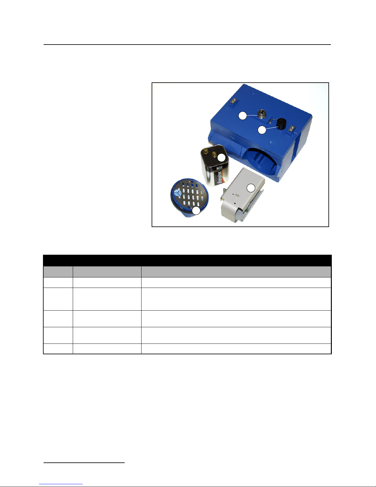
1.3 Battery Module
Components
Figures 1-3 and 1-4 identify key components of the 2191 Battery
Module.
Figure 1-3 Battery module components, top view
Table 1-3 Battery Module Components - Top View
Item No. Name Description
1 Communication Connector Connects the modules in the stack, transfers power and data.
2 Connector Cap
(Stowed on Cap Holder)
3 Lantern Battery
(Alkaline shown)
4 Door Two circular doors contain the desiccant bags, hold the battery carriers in
5 Battery Carrier Holds batteries in place and transfers power to the connectors.
Insert into the communication connector when not in use to protect the
connector from moisture damage. When the connector is in use, store the
connector cap on the cap holder.
6V alkaline or rechargeable lead-acid battery, quantity of 2.
place, and seal the module case.
1-4
2105 Interface Module
2
1
3
4
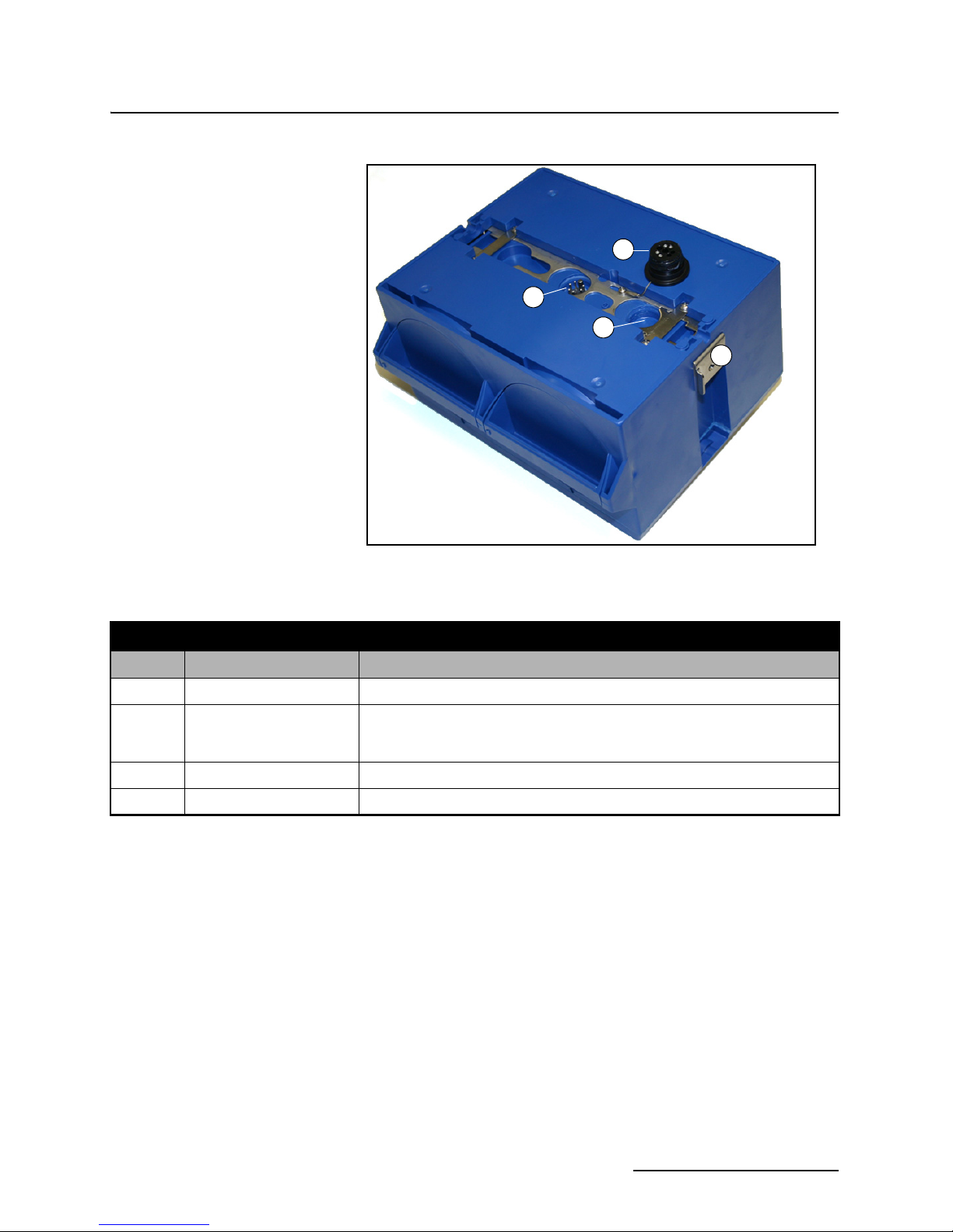
Section 1 Introduction
Figure 1-4 Battery Module Components, Bottom View
Table 1-4 Battery Module Components - Bottom View
Item No. Name Description
1 Communication Connector Connects the modules in the stack, transfers power and data.
2 Connector Plug Insert into the communication connector when not in use to protect the con-
nector from moisture damage. When the connector is in use, store the connector cap in the cap holder.
3 Plug Holder Stores the connector plug when the communication connector is in use.
4 Latch Push in to lock the module in a stack.
1-5

2105 Interface Module
Note
Section 1 Introduction
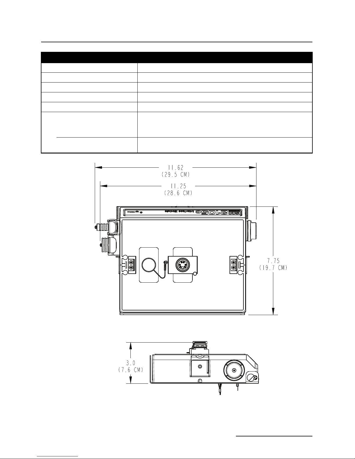
1.4 Technical
Specifications
Technical specifications for the 2105 Interface Module are given
in Table 1-5. Technical specifications for the 2191 Battery
Module are given in Table 1-6.
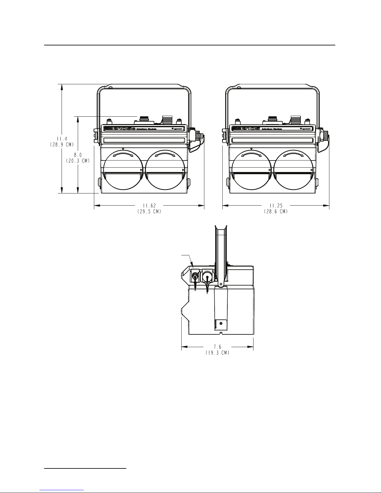
Following the specification tables are dimensional drawings to
assist in planning your installation.
Table 1-5 Technical Specifications: 2105 Interface Module
Dimensions (H x W x D) 2.9 x 11.3 x 7.5 in. 7.4 x 28.7 x 19.1 cm
Weight 2 lbs. (0.9 kg)
Material High-impact molded polystyrene, Stainless steel
Enclosure NEMA 4X, 6P, IP68
Power 7 to 26 VDC, 100 mA typical at 12 VDC, 1 mA standby, 2 A maximum.
Some other system components, including cables, have
lower voltage limits and cannot be connected in systems
powered by more than 16.6 VDC. Refer to Section 2.2 for
complete information.
Operating Temperature -4° to 140°F (-20° to 60°C)
Storage Temperature -40° to 140°F (-40° to 60°C)
Typical Battery Life Up to 254 days*
Serial Port Communication Speeds
(not cellular)
Optional Cellular Communication Serial Over IP (SOIP): CDMA (2105Ci), GPRS (2105Gi)
Data Storage 798 Kb non-volatile flash
Storage Mode Rollover, 5 bytes per reading
Storage Interval 15 or 30 seconds; 1, 2, 5, 15, or 30 minutes; or 1, 2, 4, 12, or 24 hours.
Data Types Flow Rate, Level, Rainfall, Conductivity, Dissolved Oxygen, Temperature,
Sampler Flow Pulse Output 12V Pulse; Duration 65-75 ms.
Actual battery life will vary depending upon configuration. The figure given assumes interrogation with Flowlink once a week, with a site configuration
*
of a 2105, 2150, and 2191 (using Energizer 529 batteries) and a connection speed of 38400 bps. The 2150 was configured to record level, velocity,
and flow rate every 15 minutes; total flow and battery voltage every 24 hours.
9600, 19200, and 38400 bps
Storage rate variable based on measured parameters
pH, Percent, Velocity, Volume, Total Dissolved Solids, Salinity, Phosphate, Ammonia, Nitrate, TOC, COD, Total Suspended Solids, Sludge
Index, Sludge Volume, SAC, Turbidity, Load, Input Voltage, Wireless Signal, Rainfall Intensity, Specific Conductance, Chloride, Chlorophyll, ORP,
Ammonium
1-6
2105 Interface Module
Section 1 Introduction
Table 1-6 Technical Specifications: 2191 Battery Module
Dimensions (H x W x D) 6.0 x 9.6 x 7.5 in. 15.2 x 24.4 x 19.1 cm
Weight (without batteries) 3.2 lbs. 1.4 kg
Materials Polystyrene, stainless steel
Enclosure (self-certified) NEMA 4X, 6P IP68
Batteries 6V alkaline lantern or rechargeable lead-acid lantern, quantity 2
Capacity
Alkaline Lantern Batteries
(Eveready Energizer® Model 529)
Rechargeable Lead-acid Lantern
Batteries
25 Ahrs
5 Ahrs
Figure 1-5 Specification drawing: 2105 (larger width for cellular modules)
1-7
2105 Interface Module
Section 1 Introduction
2105Ci/Gi
Antenna Connector
Cellular Only
2105
Figure 1-6 Specification drawing: 2105 mounted on 2191 battery module
1-8
2105 Interface Module
CAUTION
WARNING
Section 1 Introduction
1.5 Safety Symbols and
Hazard Alerts
This icon identifies a general hazard and is accompanied
with details about the hazard. The instruction manual
identifies the hazardous condition and any steps necessary to correct the condition. The manual presents this information in one of two ways:
Cautions identify a potential hazard, which if not avoided, may
result in minor or moderate injury. This category can also warn
you of unsafe practices, or conditions that may cause property
damage.
Warnings indicate potentially hazardous conditions. If you
do not avoid these risks, they could cause you death or
serious injury.
1-9

2105 Interface Module
Section 1 Introduction
1.6 Technical Service Although Teledyne Isco designs reliability into all of its
equipment, you can use this manual to help in diagnosing and
resolving many issues. If a problem persists, call or write the
Teledyne Isco Technical Service Department for assistance:
Teledyne Isco
Technical Service Department
P.O. Box 82531
Lincoln, NE 68501
866-298-6174 or 402-464-0231
FAX: 402-465-3001
e-mail: IscoService@teledyne.com
Simple difficulties can often be diagnosed over the phone. If it is
necessary to return the equipment to the factory for service,
please follow the shipping instructions provided by the Technical
Service Department, including the use of the Return Authorization Number specified. Be sure to include a note describing the
malfunction. This will aid in the prompt repair and return of the
equipment.
1-10

2105 Interface Module
WARNING
Teledyne Isco
Customer Service Dept.
P.O. Box 82531
Lincoln, NE 68501 USA
Phone: (800) 228-4373
Outside USA & Canada call:
(402) 464-0231
FAX: (402) 465-3022
E-mail: IscoInfo@teledyne.com
Section 2 Installation and Operation
2.1 Unpacking
Instructions
When the system arrives, inspect the contents for any damage. If
there is damage, contact the delivery company and Teledyne Isco
(or its agent) immediately.
If there is any evidence that any items may have been
damaged in shipping, do not attempt to install the unit.
Please contact Teledyne Isco (or its agent) for advice.
When you unpack the system, check the items against the
packing list. If any parts are missing, contact the delivery
company and Teledyne Isco’s Customer Service Department.
When you report missing part(s), please indicate them by part
number. In addition to the main packing list, there may be other
packing lists for various sub-components.
It is recommended that you retain the shipping cartons as they
can be used to ship the unit in the event that it is necessary to
transport the system.
Please complete the registration card and return it to Teledyne
Isco.
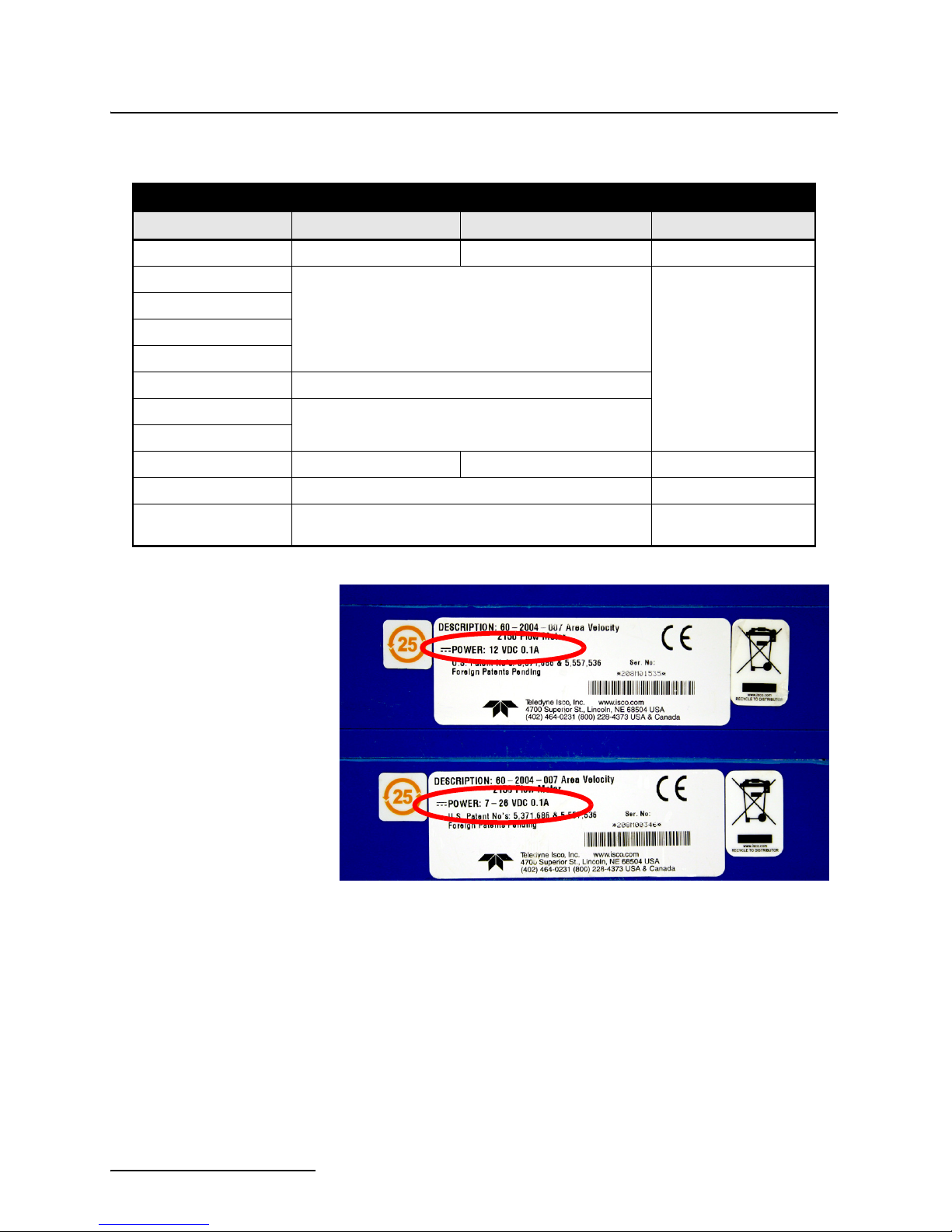
2.2 System Power 2105 modules can be powered by 7 to 26 volts. Some other 2100
system components are limited to a maximum of 16.6 volts
(12 volts typical). The voltage specification is printed on the
serial tag located on the back of the module (refer to Figure 2-1).
Table 2-1 lists the maximum voltages for all Isco 2100 instrumentation. Regardless of the capabilities of other components,
never attempt to connect a voltage module or cable to a system
using a power supply that exceeds its stated operating range.
2-1
2105 Interface Module
Section 2 Installation and Operation
Table 2-1 Voltage Specifications for 2100 System Components
Module or Cable Earlier Voltage Range Current Voltage Range Updated
2150 7-16.6 VDC 7-26 VDC March 2005
2110
2101
2103
7-16.6 VDC
2160
2102 10.2-16.6 VDC
2108
2105
RS-232 DB9 Cable 7-16.6 VDC 7-26 VDC January 2009
RS-232 USB Cable 7-26 VDC N/A
Sampler Interface Cable
7-26 VDC
12VDC
N/A (Cable is powered
from sampler.)
N/A
Figure 2-1 Identifying the 2150 voltage specification
2-2
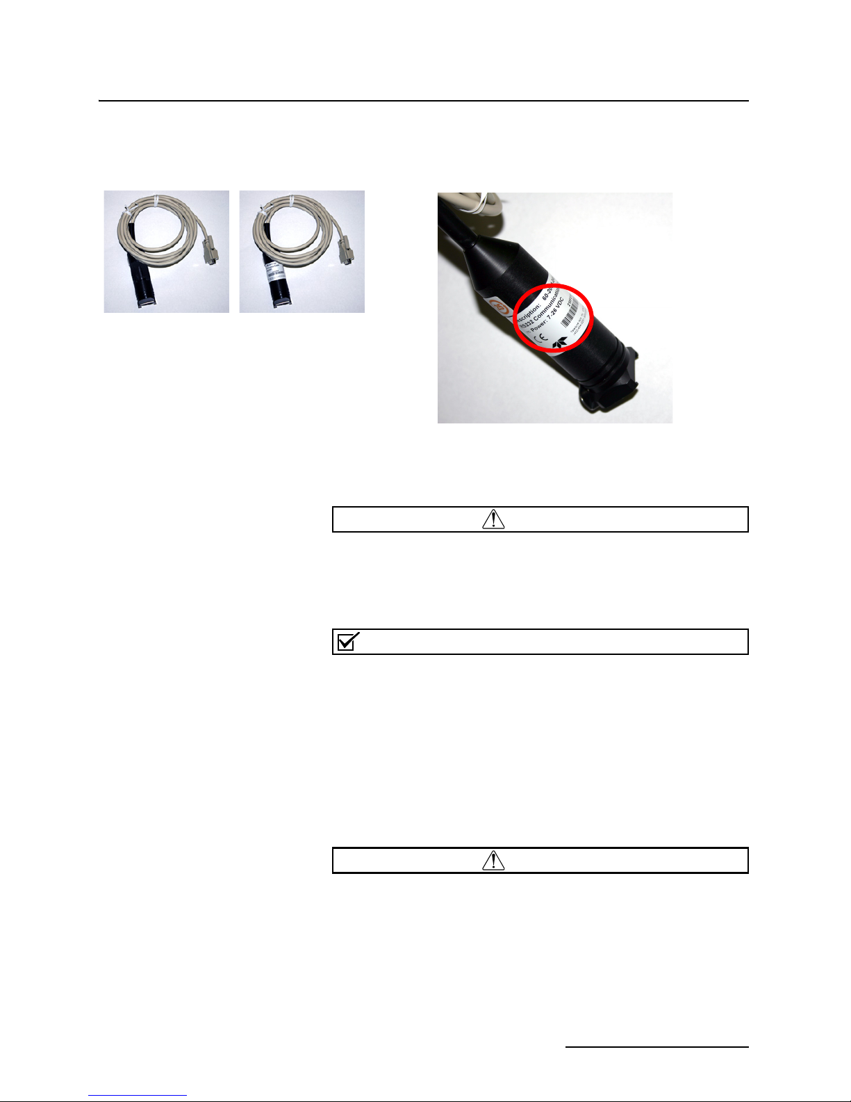
The module crown connector on the earlier RS-232 DB9 digital
WARNING
Note
WARNING
Lower Voltage
DB9 Cable
Higher Voltage
DB9 Cable
communication cable is unmarked. The connector on the 26-volt
cable has a serial tag specifying the higher voltage (Figure 2-2).
Figure 2-2 Identifying the voltage specification on the DB9 cable
2105 Interface Module
Section 2 Installation and Operation
2.3 Installation
Preparation
Injury and/or equipment damage can result from
connecting modules or cables to a power source exceeding
the specified operating voltage range. Check labeling on all
modules and cables for voltage ranges.
All connected system components should share a common
supply ground.
The 2100 Series components are often installed in confined
spaces. Some examples of confined spaces include manholes,
pipelines, digesters, and storage tanks. These spaces may become
hazardous environments that can prove fatal for those unprepared. These spaces are governed by OSHA 1910.146 and require
a permit before entering.
Avoid hazardous practices! If you use these instruments in
any way not specified in this manual, the protection
provided by the instruments may be impaired; this will
increase your risk of injury.
2-3
2105 Interface Module
WARNING
CAUTION
Section 2 Installation and Operation
The installation and use of this product may subject you to
hazardous working conditions that can cause you serious
or fatal injuries. Take any necessary precautions before
entering a worksite. Install and operate this product in
accordance with all applicable safety and health
regulations, and local ordinances.
Follow the instructions below to install your 2105 module. Most
of these instructions are similar for the 2105Ci and 2105Gi.
Where there are specific differences between the modules, they
are identified.
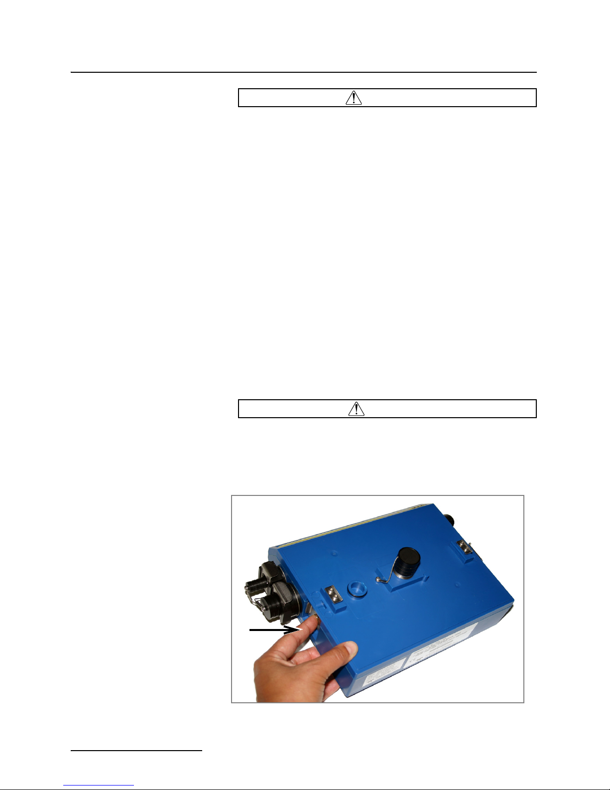
2.3.1 Latches - Locking and
Unlocking
Latches must be operated to stack and unstack the modules, and
to gain access to the vent screw. The latch is normally locked, but
you must unlock it to install the module on top of another module
in a stack.
To unlock the latch, push in the latch release on the connector
side of the module (Figure 2-3).
To lock the latch, push in the latch on the desiccant side of the
module (Figure 2-4).
The latch can be damaged by applying too much force. Never
press on both sides at the same time. Do not force the latch if it
is obstructed. While some degree of pressure must be applied
to slide the latch, the ends of the latches should never be bent.
Figure 2-3 Unlocking the latch
2-4
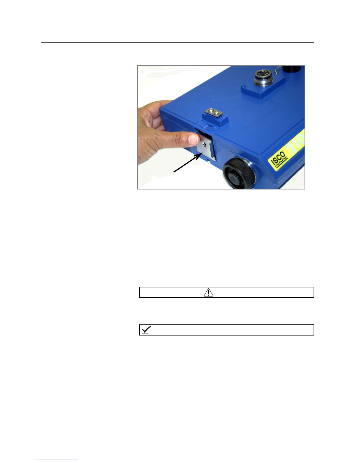
Figure 2-4 Locking the latch
CAUTION
Note
2105 Interface Module
Section 2 Installation and Operation
Latches will “click” when they are fully locked or unlocked.
2.3.2 Communication
Connectors
When a communication connector is not in use, the connector should always be capped. The cap seals the connector
to prevent corrosion, prevent moisture from entering the unit,
and improve communications.
When a communication connector is in use, store the cap on the
holder next to the connector. The communication connector will
be sealed by its mating connector.
Caps PUSH ON and PULL OFF. Do not rotate the caps to
remove them from the connectors.
For modules to correctly stack and lock together, protective
caps between the modules must be stored on the holders.
2-5
2105 Interface Module
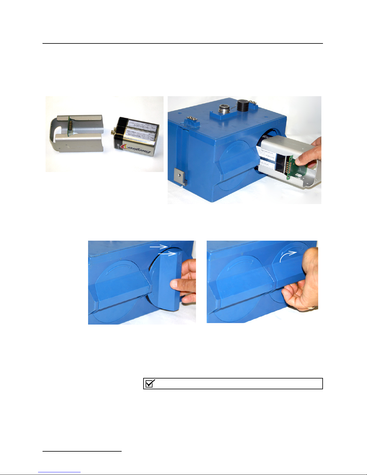
Note
1. Load the lantern battery into the
carrier.
2. Insert the carrier and battery into the module.
Note the position of the carrier’s connector; it
must be aligned toward the center of the module.
3. Align the marks indicated and
insert the door.
4. Rotate the door
1
/4 turn clockwise.
Repeat this procedure to install
the second battery.
Section 2 Installation and Operation
2.3.3 Installing the Batteries The 2191 battery module requires two lantern batteries. The
figures below show a 6 VDC alkaline battery. Rechargeable 6
VDC lead-acid batteries are also available from Teledyne Isco.
To install the batteries, follow the instructions below.
Figure 2-5 Loading the 2191 Battery module
2-6
The batteries should always be replaced as a pair. Never mix
old and new batteries.
2105 Interface Module
LED
Indicator
Section 2 Installation and Operation
2.4 Stacking Modules The 2105 can be located anywhere within a stack of up to four
2100 Series networked modules. It will draw its power from the
same source as the rest of the stack.
To connect the 2105 with another 2100 Series module:
1. On the top of the 2100 Series module, remove the cap and
stow it on the holder. This exposes the communication connector on the module.
2. Inspect the module’s communication connector. It should
be clean and dry. Damaged O-rings must be replaced.
3. If you are using the metal carrying handle, insert it
between the top two modules, with the handle turned
toward the rear of the stack (opposite the yellow labels).
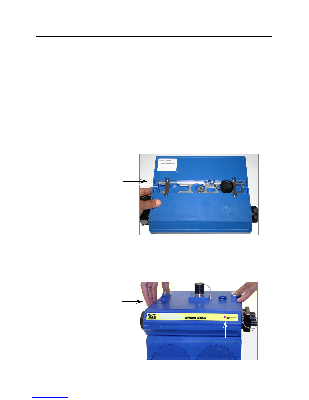
4. Unlock the 2105’s latch by pressing in on the latch release.
5. Underneath the 2105, remove the cap from the lower communication connector and stow it in the holder.
Figure 2-6 Unlock latch and stow the cap
6. Gently press the modules together and lock the 2105’s
Figure 2-7 Aligning the modules
latch (desiccant side). The red LED on the front of the unit
will blink during the start-up routine to indicate the 2105
is operating.
2-7
2105 Interface Module
Note
Section 2 Installation and Operation
2.5 Connecting to
Flowlink
Once the system is installed, you will configure it in a new or
existing site using Isco’s Flowlink software.
The 2105 and 2105Ci/Gi Modules require Flowlink version
5.12.052 or later.
The first time you connect to the site, you must connect your
computer directly to the stack using Isco’s RS232 connect cable
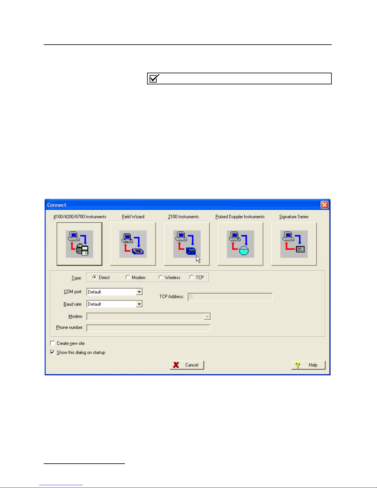
or USB port connect cable. Open Flowlink and go to the Connect
screen (Figure 2-8) by either selecting it from the pull down
menu or clicking on the Quick Connect icon.
Make sure the connection Type is Direct, and click on the 2100
Instrument icon to connect. Upon initial connection, Flowlink
creates a site file and adds it to the database. If the system
detects the addition of a new module to an existing site, it will
display the Site Resolution screen (Figure 2-9). Otherwise, it will
display the Site Info screen (Figure 2-10).
Figure 2-8 Flowlink connect screen
2-8
2105 Interface Module
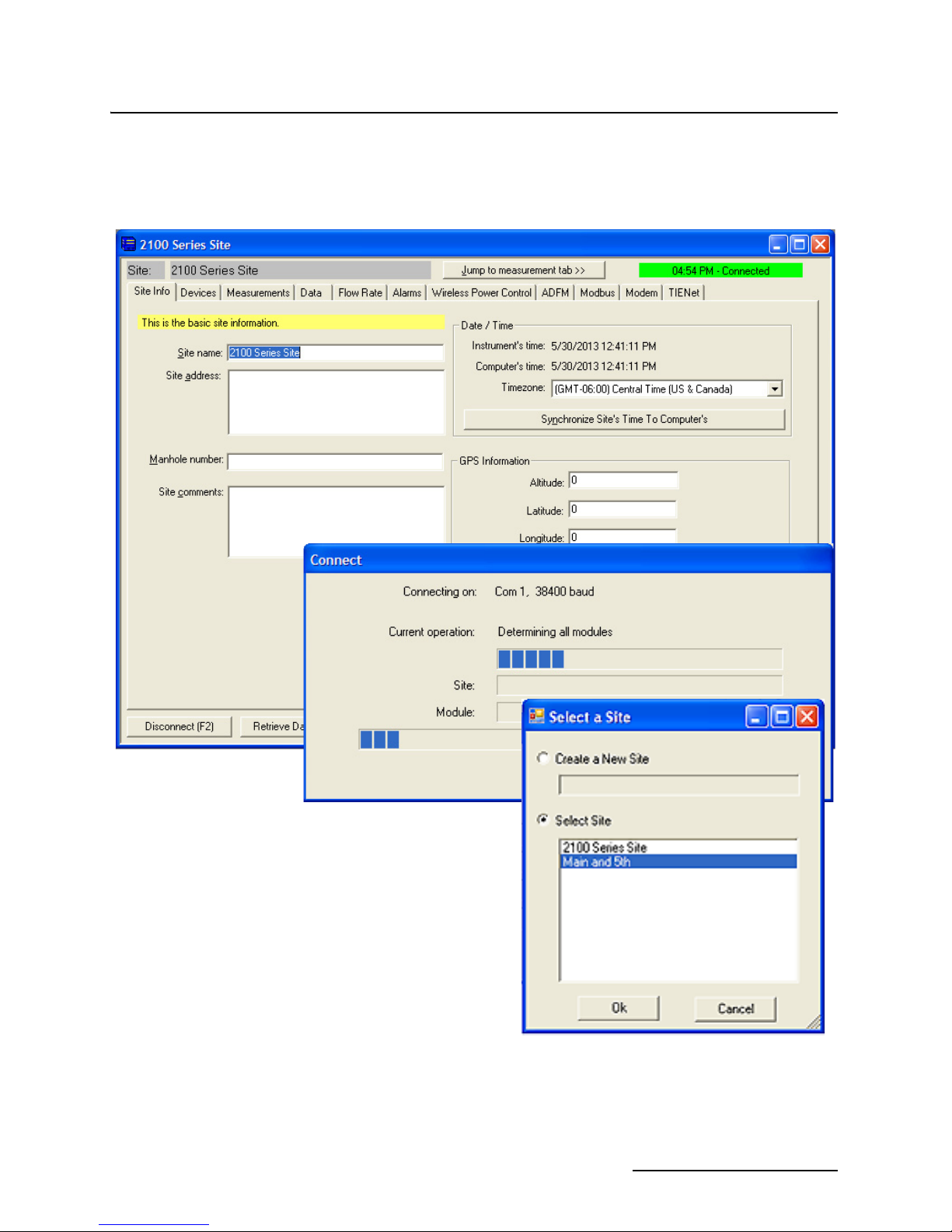
Section 2 Installation and Operation
To add the new module to an existing site, select the appropriate
site and click OK. To create a new site, select Create a New Site.
Click in the name field, enter the name for the site, and click OK.
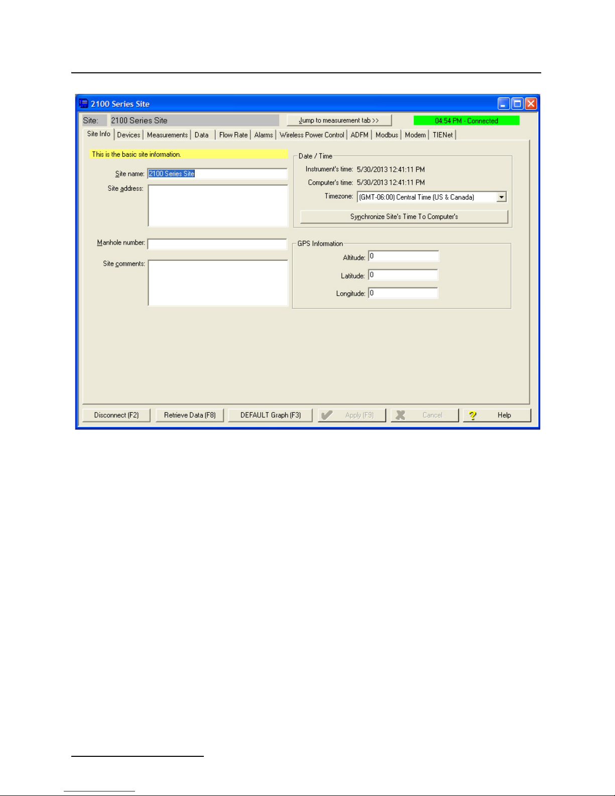
Upon connection, the Site Info tab will appear.
Figure 2-9 Site resolution screen
2-9
2105 Interface Module
Section 2 Installation and Operation
Figure 2-10 Site Information screen
2-10
 Loading...