

Page 1

OPERATING INSTRUCTIONS FOR
IR7000
NDIR Gas Analyzer
REV. 3
Page 2

NDIR Gas Analyzer Safety
Copyright © 2000 Teledyne Analytical Instruments.
All Rights Reserved. No part of this manual may be reproduced, transmitted,
transcribed, stored in a retrieval system, or translated into any other language or computer
language in whole or in part, in any form or by any means, whether it be electronic,
mechanical, magnetic, optical, manual, or otherwise, without the prior written consent of
Teledyne Analytical Instruments, 16830 Chestnut St. City of Industry, Ca. 91748
Warranty
This equipment is sold subject to the mutual agreement that it is warranted by us to
be free from defects of material and of construction, and that our liability shall be limited
to replacing or repairing at our factory (without charge, except for transportation), or at
customer plant at our option, any material or construction in which defects become
apparent within one year from the date of shipment, except in cases where quotations or
acknowledgments provide for a shorter peri o d. C omponents manufactured by others bear
the warranty of their manufacturer. This warranty does not cover defects caused by wear,
accident, misuse, neglect or repairs other than those performed by Liston or an authorized
service center. We assume no liability for direct or indirect damages of any kind and the
purchaser by the acceptance of the equipment will assume all liability for any damage
which may result from its use or misuse.
We reserve the right to employ any suitable material in the manufacture of our
apparatus, and to make any alterations in the dimensions, shape or weight of any parts, in
so far as such alterations do not adversely affect our warranty.
Important Notice
This instrument provides measurement readings to its user, and serves as a tool by
which valuable data can be gathered. The information provided by the instrument may
assist the user in eliminating potential hazards caused by his process; however, it is
essential that all personnel involved in the use of the instrument or its interface be
properly trained in the process itself, as well as all instrumentation related to it.
The safety of personnel is ultimately the responsibility of those who control process
conditions. While this instrument may be able to provide early warning of imminent
danger, it has no control over process conditions, and it can be misused. In particular, any
alarm or control systems installed must be tested and understood, both as to how they
operate and as to how they can be defeated. Any safeguards required such as locks,
labels, or redundancy, must be provided by the user or specifically requested of Teledyne
Analytical Instruments at the time the order is placed.
Therefore, the purchaser must be aware of the hazardous process conditions.
The purchaser is responsible for the training of personnel, for providing hazard warning
methods and instrumentation per the appropriate standards, and for ensuring that hazard
warning devices and instrumentation are maintained and operated properly.
Teledyne Analytical Instruments cannot accept responsibility for conditions
beyond its knowledge and control. No statement expressed or implied by this document
or any information disseminated by the manufacturer or its agents, is to be construed as a
warranty of adequate safety control under the user’s process conditions.
Teledyne Analytical Instruments, - Rev. 3
Page 3

Table of Contents
Important Safety Information....................................................S-1
S.1 General Format.............................................................S-1
S.2 Specific Hazards...........................................................S-2
Introduction....................................................................................1
1.0 Overview .......................................................................... 2
1.1 Standard Features........................................................... 4
1.2 Optional Features............................................................ 4
1.3 IR Detection ..................................................................... 6
1.4 Operator Interface........................................................... 6
Operational Theory........................................................................8
2.1 Introduction ..................................................................... 8
2.2 Optical Bench.................................................................. 8
2.3 Electronics..................................................................... 11
2.3.1 Power Supply Board........................................... 11
2.3.3 Main Board.......................................................... 12
2.3.4 Display Board...................................................... 14
2.3.5 I/O Board ............................................................. 14
2.4 Sample System.............................................................. 14
2.5 Internal Gas Handling System...................................... 16
Installation....................................................................................18
3.1 Overview ........................................................................ 18
3.2 Unpacking and Installation........................................... 18
3.3 Mounting the Analyzer.................................................. 18
3.4 Gas Connections........................................................... 19
3.5 Sample System Considerations................................... 20
3.6 Electrical Connections.................................................. 21
3.6.1 Analog Output..................................................... 22
3.6.2 Analog Output Connections.............................. 25
3.6.3 Solenoid Valve Connections.............................. 25
3.6.4 Optional Relay Outputs...................................... 26
3.6.5 Digital I/O Option ................................................ 27
3.6.6 RS-232 Cable....................................................... 28
3.6.7 Power Connections............................................ 29
Teledyne Analytical Instruments., - Rev. 3
Page 4

NDIR Gas Analyzer Safety
Operation......................................................................................31
4.1 Overview ........................................................................ 31
4.2 The SETUP Menu........................................................... 31
4.3 The MODE Menu............................................................ 39
Calibration....................................................................................46
5.1 Overview ........................................................................ 46
5.2 Typical Sample System ................................................ 46
5.3 Manual Calibration........................................................ 47
5.3.1 Manual Zero Calibration..................................... 47
5.3.2 Manual Span Calibration.................................... 48
5.4 AUTO Calibration .......................................................... 50
5.5 Calibration Issues ......................................................... 51
Maintenance.................................................................................53
6.1 Scheduled Maintenance ............................................... 53
6.1.1 Cleaning .............................................................. 53
6.1.2 Particle Filter....................................................... 53
6.2 Service ........................................................................... 55
6.2.1 Removing the Optical Bench............................. 55
6.2.2 Cleaning the Sample Cell................................... 58
6.2.3 Replacing the IR Source .................................... 59
6.2.4 Replacing the Battery (Portable Model Only)... 59
6.2.5 Changing the Fuse ............................................. 60
6.3 Display Messages ......................................................... 61
6.3.1 Error Messages................................................... 62
6.3.2 Normal Operation Messages ............................. 65
6.3.3 Normal Operator Induced Messages ................ 66
Appendix ......................................................................................69
A-1 Specifications.................................................................... 69
A-2 Recommended Spare Parts List .................................. 71
A-3 RS-232 Communication Protocol .................................... 72
A-3.1 Codes for "e" Type Messages........................... 76
A-3.2 Codes for "s" Type Messages........................... 77
A-3.3 Codes for "c" Type Messages........................... 77
A-3.4 Codes for “m” Type Messages.......................... 78
A-3.5 Codes for “a” Type Messages........................... 78
Addendum A……………………………………………………………..
Configuration and Compliance Certificates
Addendum B……………………………………………………………..
Automatic Calibration Electrical Connection Diagram
Teledyne Analytical Instruments, - Rev. 3
Page 5
Important Safety Information
S.1 General Format
Important information relating to health and safety of personnel,
possible equipment damage and special instructions regarding instrument
setup and operation are setoff and highlighted within this manual. The
following format will be used in this manual to indicate safety hazards and
special instructions:
Symbol Heading Typeface and
Description
WARNING 12 poi nt bol d t ypefa ce.
Contains important
informa tion w hi ch i f
ignored could result in
persona l in jury or dea th.
CAUTION 12 poi nt bol d t ypefa ce.
Contains important
informa tion w hi ch i f
ignored could result in
dam ag e t o t h e syst em.
NOTE
No Symbol
12 point Italic typeface.
Contains important or helpful
information relating to the
setup and/or operation of the
system.
Read this instruction manual carefully and familiarize yourself
thoroughly with its contents. Do not ignore any warnings or
cautions or operate this equipment with any safety feature
Page 6
Safety IR7000
defeated or inoperable. Failure to heed warnings or cautions can
result in injury or death as well as damage to the instrument.
S.2 Specific Hazards
WARNING: ELECTRICAL HAZARD! Hazardous voltage is present inside. Keep
away from Live Circuits. Under no circumstances should untrained
personnel open any panel or remove any cover, lid or wiring
harness without proper guidance and supervision.
Component replacement, internal adjustments and electrical service
must be made by qualified maintenance personnel. Always disconnect the
power cable and discharge circuits before servicing the equipment. To
avoid accidental power up, Liston recommends using an electrical lockout device whenever maintenance is to be performed. Disconnect power to
any other equipment connected to the instrument to avoid the possibility
of component failure and transmission of dangerous voltage through
signal connections.
WARNING: FLAMMABLE GAS HAZARD! EXPLOSION HAZARD! TOXIC GAS
HAZARD! Do not operate this instrument in an explosive
atmosphere. Read all documentation that comes with this
instrument especially any application notes or addenda which,
among other important details, may specify the nature and
properties of the gas to be analyzed.
Unless specifically designed for hazardous environment application,
this instrument is not designed to handle explosive or flammable gases.
Exposed electrical terminals pose a substantial risk of ignition if powered
in the presence of flammable gas. The sample system is not appropriate
for handling toxic, flammable or explosive gases!
If your application requires using toxic, flammable or explosive gases
for analysis or calibration, please consult the factory. An explosion proof
instrument with enhanced sample system is available as an option.
WARNING: ELECTRICAL HAZARD! This instrument must be properly
grounded.
To avoid shock hazard, the instrument chassis and cabinet must be
connected to an electrical ground. The instrument is equipped with a three
conductor AC power cable. This cable must be plugged into an approved
three-contact electrical outlet. The power jack and plug of the power cable
meet International Electro-Technical Commission (IEC) safety standards.
When replacing this cable, use only the proper replacement cable as listed
in the Spare Parts Listing in the Appendix.
S-2 Teledyne Analytical Instruments., - Rev. 3
Page 7
NDIR Gas Analyzer Safety
WARNING: Do not attempt to service or make adjustments to this equipment
while working alone.
Whenever servicing or adjusting this equipment, notify your supervisor
and have another person capable of rendering first aid standby in case of
an accident.
WARNING: Do not substitute parts or modify this instrument.
The IR7000 was designed and tested at the factory. The quality, safety and
workmanship inherent in this product is a result of careful design,
selection and assembly of components. Any use of non-authorized
replacement parts can impair the functioning of this system. In addition to
voiding your warranty, any substitution of non-authorized replacement
parts or unauthorized modifications to the instrument can create an
unnecessary risk of harm. Return the analyzer to Teledyne Analytical
Instruments for service and repair to ensure proper functioning of the unit.
WARNING: Do not operate a damaged instrument.
If any of the built-in safety features of this instrument is impaired,
either through physical damage, excessive moisture, or any other reason,
IMMEDIATELY REMOVE POWER. Do not use the instrument until
safe operation can be verified by service-trained personnel. If necessary,
return the instrument to Teledyne Analytical Instruments. for service and
repair.
DANGER
HIGHLY TOXIC AND/OR FLAMMABLE LIQUIDS MAY BE PRESENT IN THIS MONITORING SYSTEM
PERSONAL PROTECTIVE EQUIPMENT MAY BE REQUIRED WHEN SERVICING THIS SYSTEM.
HAZARDOUS VOLTAGES EXIST ON CERTAIN COMPO NENT S INTERNALLY WHIC H MAY
PERSIST FOR A TIME EV EN AFTER THE POWER IS TURNED OFF AND DISCONNECTED.
ONLY AUTHORIZED PERSONNEL SHOULD CONDUCT MAINTENANCE AND/OR SERVICING.
BEFORE CONDUCTING ANY MAINTENANCE OR SERVICING CONSULT WITH AN AUTHORIZED
SUPERVISOR OR MANAGER.
S-3 Teledyne Analytical Instruments., - Rev. 3
Page 8

Safety IR7000
THIS PAGE INTENTIONALLY LEFT BLANK.
S-4 Teledyne Analytical Instruments., - Rev. 3
Page 9

Introduction
Page 10
Introduction 1 IR7000
1.0 Overview
The Teledyne analytical Instruments Model IR7000 Non-Dispersive
Infrared Gas Analyzer is a versatile microprocessor based analyzer for
measuring or monitoring a gas stream. The IR7000 analyzer is available in
a variety of configurations to suit most applications.
The IR7000 series analyzer is designed for rapid monitoring of a
process gas stream. Four user definable chart ranges are available for
accurate monitoring over the full range of the process gas composition. A
trace analysis unit is available for analysis at low ppm levels. This manual
describes the setup and operation of the Model IR7000. It also covers
particular features of the other analyzers in the IR7000 series where setup
and operation differs from the standard unit.
MODEL DESCRIPTION
IR7000 Panel/19” Rack Mount – CE Mark
IR7010 Split Architecture, Analysis Unit – Explosion Proof
IR7000P Portable Battery Operated with AC Charger
IR7000T Similar to IR7000 for Trace Analysis
2 Teledyne Analytical Instruments, - Rev. 3
Page 11

NDIR Gas Analyzer Introduction 1
IR7000D Dual Optical Bench for Monitoring 2 Gases
IR7000B Wall Mount Unit
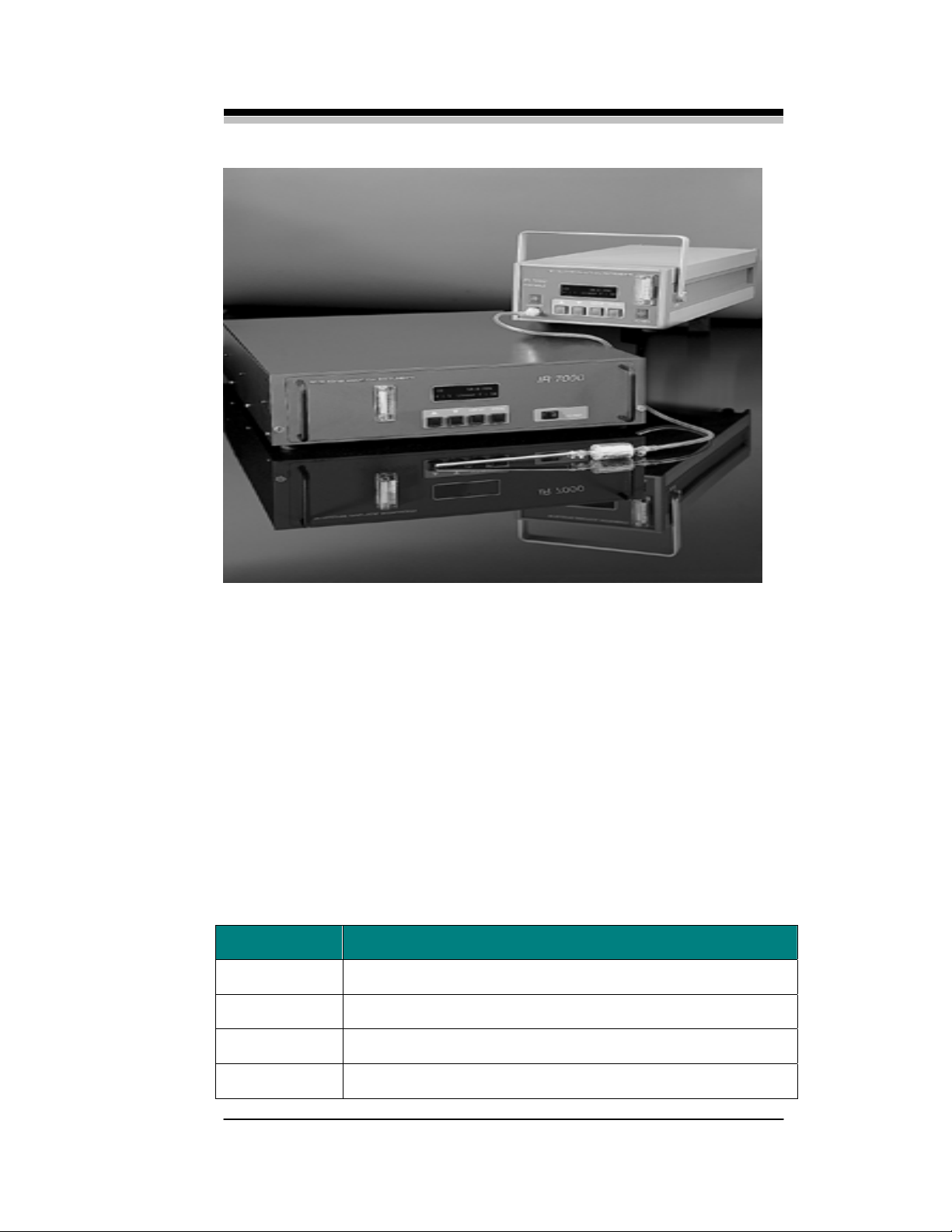
The standard rack mount model IR7000 is shown in Figure 1-1 and
the portable IR7000P is shown in Figure 1-2. The explosion proof models
have the analysis unit installed in an explosion proof housing and employ
steel tubing and fittings in the sample system. The control unit on these
models is separate from the analyzer and generally located outside the
hazardous environment.
Teledyne Analytical Instruments., - Rev. 3 3
Page 12

Introduction 1 IR7000
1.1 Standard Features
The following features are standard on the IR7000 series of analyzers:
• User selected automatic zero and span calibration
• Linearized output over the entire full scale range eliminating
the need for separate instrument ranges to achieve full span
• Closed sample path is not exposed to ambient air eliminating
the need for purging of the cell compartment
• Four user-definable chart ranges plus auto-ranging
• Selectable analog output: 0–1, 0–5, or 0–10V or optionally, a
4–20mA non-isolated or isolated current output
• High and low alarms or limits with adjustable setpoints. The
alarms are configured at the factory for either latching or nonlatching operation
• Modular design for easy maintenance
• Configured to easily accommodate an optional oxygen channel
for simultaneous oxygen analysis at either 0–25% or 0–100%
• Patented IR detector uses a sensitive mass flow sensor and a
dual chamber for rapid analysis of IR absorption in a sample
flow
• Unique optical bench design eliminates mechanical chopping
of IR source
• IR bench does not require tuning for maximum signal like
other optical NDIR systems
• Self-diagnostic software installed
• Easy setup and maintenance
• Easy to operate with all user controls accessible from the front
panel
• CE Mark (IR7000 Rack and battery portable)
1.2 Optional Features
4 Teledyne Analytical Instruments, - Rev. 3
Page 13

NDIR Gas Analyzer Introduction 1
To extend the versatility of the Ir7000 series of analyzers, many
options are available.
• Dual optical bench for simultaneous monitoring of 2 gases
• Oxygen channel (0–25% or 0–100%). The IR7000 series easily
accepts Teledyne analytical Instruments oxygen
electrochemical cell for measuring oxygen levels in the process
gas.
• RS-232 port for control input and data output via a remote
computer
• 4–20ma analog current output either isolated or non-isolated
Teledyne Analytical Instruments., - Rev. 3 5
Page 14

Introduction 1 IR7000
• Relay outputs. Single pole double throw (SPDT) relays driven
off the status signal, high, and low limit alarms can be installed
for triggering status alarms, indicators, or other customer
supplied peripherals.
• External sample system. The instrument can be supplied with a
sample handling system ensuring safe delivery of conditioned
sample gas to the analyzer.
• Z-Purge system. The split-architecture models can be fitted
with a Z-Purge system for automatic purging of the NEMA-4
enclosure.
1.3 IR Detection
Central to the IR7000 analyzer is the unique patented IR detector. It
incorporates 2 chambers in optical series at the end of a gold-coated
sample cell. The chambers are connected through a tiny orifice. IR is
differentially absorbed in the 2-chambered detector and causes a mass
flow between the chambers. The modulation of the IR signal causes the
chambers to quickly readjust and the flow reverses. A sensitive mass flow
sensor located in the tiny orifice between the 2 chambers senses the flow
in both directions and outputs a signal related to the concentration. A
high-resolution electronic circuit is employed to provide synchronous
detection of the flow sensor’s signal. This circuit allows the IR7000 to
measure gas compositions over a wider range of the infrared spectrum
than conventional photon-based IR analyzers.
1.4 Operator Interface
Except for the split architecture models (Explosion Proof), the
analysis and control sections are housed together in a single compact
metal housing. A NEMA-4 enclosure is used on the IR7000B wall
mountable model.
All operator input and display of process information takes place
from the panel (or on the control section panel for the split architecture
instruments). There are minor differences in the location of some of the
components among the different models within the IR7000 series but each
instrument has the following front panel components:
• Display—vacuum fluorescent with 2 lines of 16 characters.
The display sends data and information to the user about the
process and guides the operator through the calibration and
operation.
6 Teledyne Analytical Instruments, - Rev. 3
Page 15

NDIR Gas Analyzer Introduction 1
• Input Buttons—4 push buttons are installed on the front panel
and are used to enter data and set operational modes.
• Flowmeter—an integral flowmeter is mounted on the front
panel for monitoring the sample flow through the instrument.
• Power Switch—an off/on switch is mounted on the front panel
for powering up the instrument.
• Sample Pump Switch (IR7000P only)—this switch controls
the operation of the sample pump on portable models.
• Sample Pump Connector (IR7000P only)—a quick
disconnect nylon fitting is mounted on the front panel of
portable models for attaching the sample probe to the
instrument.
.
Teledyne Analytical Instruments., - Rev. 3 7
Page 16

Operational Theory
2.1 Introduction
The IR7000 is a microprocessor controlled, single beam infrared
analyzer that employs an electronically modulated IR source with no
moving parts.
The analyzer is composed of 2 subsystems:
• Optical Bench
• Electronics
2.2 Optical Bench
At the heart of the IR7000 NDIR Gas Analyzer is the patented dual
chambered balanced detector. The advanced detector design offers higher
sensitivity and selectivity with a greater dynamic range compared to other
IR detectors in the marketplace.
The optical bench is shown in Figure 2-1. It consists of:
• Sample cell
• Detector
• IR source
• Filter cell
• Windows and seals
The sample cell is a gold coated glass tube (metal Tube Optional)
through which the sample gas flows. At one end of the sample cell,
infrared energy is generated by a modulated IR source. The modulation is
achieved electronically by feeding the IR source a 4 Hz square wave
generated by the source control circuit on the main PC board. The
electronic modulation is very stable and eliminates the need for
mechanical choppers and motors routinely used in other IR systems. At
the other end of the optical bench is the detector and filter cell.
Page 17
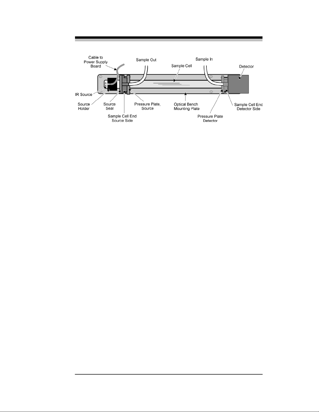
NDIR Gas Analyzer Operational Theory 2
Figure 2-1: Optical Bench Components
The detector consists of 2 chambers filled with the gas of interest in
optical series with a sensitive mass flow sensor. The sensor measures a
fluctuating mass flow between the 2 chambers due to a differential in
infrared absorption between the chambers.
The 2 chambers of the detector are of unequal volume, the first
chamber, called the primary chamber, is much smaller than the trailing
chamber, or secondary chamber. A small passageway connects the 2
chambers and contains the mass flow sensor. During assembly at the
factory, both chambers are filled with the gas of interest and due to the
unequal volume, a vastly different optical path length exists between the
chambers.
Initially, with only nitrogen (zero gas) passing through the sample
cell, pulsed IR radiation from the source passes through the cell. Since this
is the zero gas, no differential absorption takes place. At the rear of the
sample cell an IR transparent window (typically sapphire but may be some
other material depending on the application) allows the radiation to pass
into the primary detector chamber. Due to the heteroatomic nature of the
gas contained within the chambers (identical to the gas to be monitored),
IR absorption takes place at a few characteristic wavelengths
corresponding to the most strongly absorbed lines for that particular gas in
the IR spectrum. The remaining radiation passes through to the secondary
chamber.
The secondary chamber has a much greater path length and therefore
additional absorption takes place but at different energies. Due to the
longer residence time of the optical beam in this chamber, absorption
occurs at weaker absorption bands in the IR and accounts for the less
intense absorption relative to the primary chamber. The remaining
unabsorbed energy is eventually dissipated.
Essentially, the front chamber absorbs IR differentially at specific
wavelengths characteristic of the gas of interest within the detector
Teledyne Analytical Instruments., - Rev. 3 9
Page 18

Operational Theory 2 IR7000
chamber while the rear chamber absorbs radiation at primarily weaker
absorption bands. The absorption causes the gas to heat up and the
differential nature of the absorption process causes the front chamber to
heat up more than the rear chamber. Since the chambers are charged with
gas, the pressure in the primary chamber becomes higher than in the
secondary chamber. This pressure differential causes a net flow of gas
from the primary chamber to the secondary chamber through a tiny orifice
connecting the 2 chambers. The gas cools in quick order and the flow
reverses until the pressures are once again equal.
A mass flow sensor is placed in the orifice between the 2 chambers
and senses the mass transport between them. It is designed in such a
manner as to be able to sense minute flows in either direction. The sensor
produces a signal resulting from an electronic imbalance each time mass
flow is detected (in either direction) through the orifice. The signal is
passed along to a preamplifier and then to a voltage to frequency converter
for enhanced signal processing. The microcontroller retains this
information as a zero gas reading for calibration and offset in real
measurements.
When the process is repeated and a span gas is introduced into the
sample cell, a slightly different condition exists. Now IR absorption takes
place within the sample cell. Less energy is received at the detector. But
since the primary chamber is smaller than the secondary chamber and
differential absorption takes place at predominately strongly absorbing
wavelengths within the primary chamber, the difference in energy of the
gas in the primary chamber is less than when there is no IR absorption in
the sample cell. The energy of the gas in the secondary chamber is also
less but the change is not as dramatic. Hence the patented balanced design
detector produces a different signal when an IR absorbing gas is
introduced in the sample cell. The resulting signal is inversely related to
the concentration of the gas of interest in the sample cell.
Between the IR window and the detector is the filter cell. Depending
on the nature of the sample gas, some applications could experience
interference in the absorption band spectra. For instance, both CO and CO
absorb at wavelengths in the IR very close to each other. The presence of
CO2 could produce a measurement error in a system designed to detect
CO. The filter cell is a sealed volume of gas specifically designed to
“comb out” the offending absorption line or lines before the radiation
reaches the detector. The filter cell in some cases acts as a thermal barrier
to keep the detector from experiencing sudden temperature fluctuations.
2
10 Teledyne Analytical Instruments., - Rev. 3
Page 19
NDIR Gas Analyzer Operational Theory 2
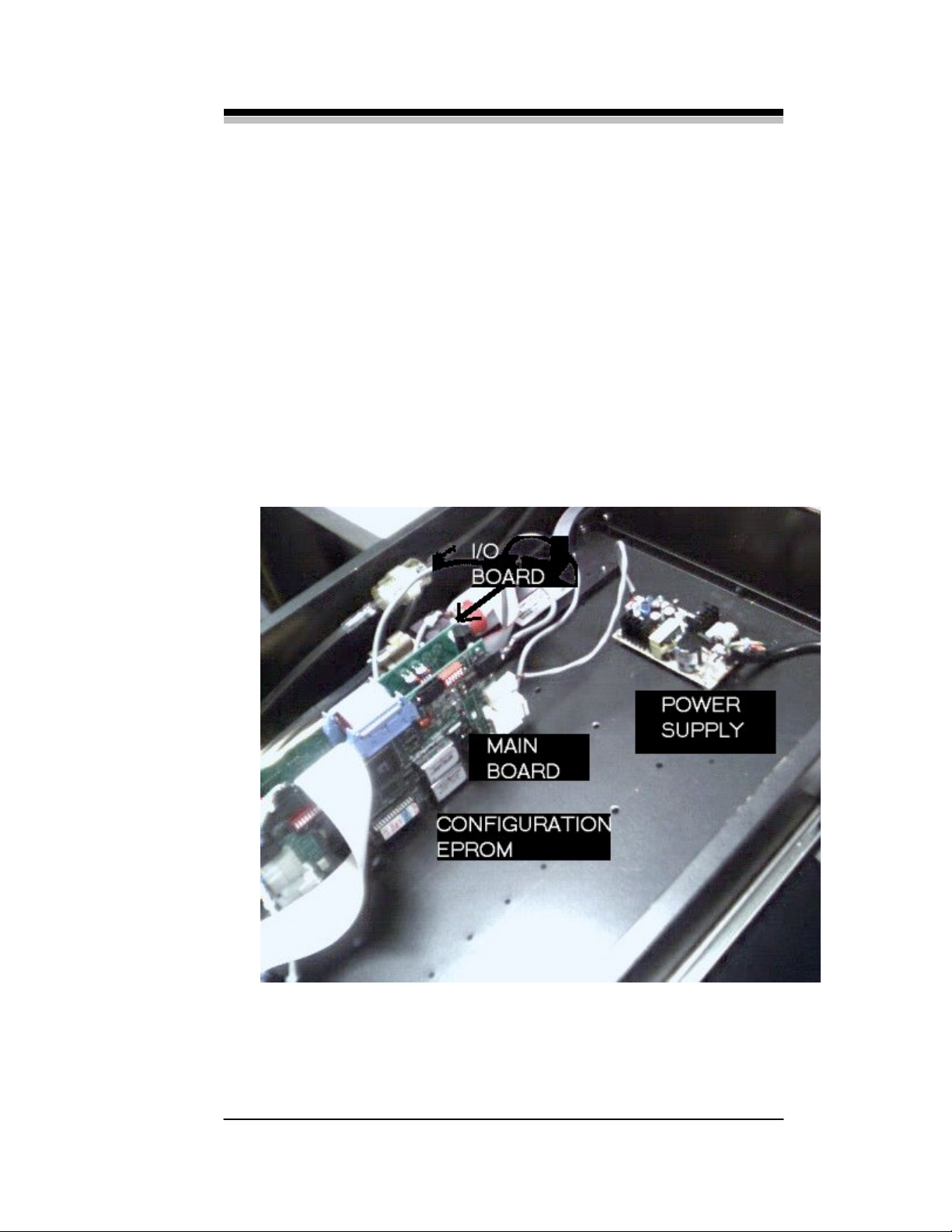
2.3 Electronics
The IR7000 uses a sophisticated microprocessor to control the signal
processing, I/O, and display functions within the analyzer. Custom
EPROMs are installed with permanently stored data and routines specific
to the customer’s application. Depending on what options are installed, 2
or more PCB’s are used in the electronic subsystem. Figure 2-2 shows the
location of the boards in the portable model. Other models are similar but
mount the boards differently.
2.3.1 Power Supply
This unit is externally powered by either 120 or 230 VAC. Fuses are
located on the back panel for circuit protection.
Figure 2-2: PC Board Identification and Location
Teledyne Analytical Instruments., - Rev. 3 11
Page 20

Operational Theory 2 IR7000
2.3.3 Main Board
In effect, the main board imports an analog signal from the
preamplifier and outputs a digital signal. A lot of signal conditioning and
processing is performed along the way. Major functions of this board
include:
• Amplification
The signal from the detector is amplified
• Filter
The analog signal is filtered and conditioned
• A to D Converter
The analog signal is digitized using a voltage to frequency
converter
• Microprocessor
Encodes both the amplitude and phase of the digital signal
Counts, integrates, and stores the signal
Handles input and output to and from the main board
• Linearizer
Scales and linearizes the signal using data and algorithms
permanently stored in the microprocessor
• Filter
De-spikes, pre-filters and filters the signal again with a
filter rate chosen by the operator
The main board receives the raw signal from the detector and
amplifies it. In the analog circuit portion of the main board, the signal is
filtered to remove any electrical interference before passing it along to the
digital section as a relatively clean sine wave of several volts.
The sine wave is digitized using an onboard voltage to frequency
converter. In this process, both the amplitude and phase of the digital
signal are encoded and integrated. The microprocessor counts the digital
pulses and linearizes it using a 7th order polynomial whose coefficients
were determined at the factory based on the particular detector.
12 Teledyne Analytical Instruments., - Rev. 3
Page 21
NDIR Gas Analyzer Operational Theory 2
The data is linearized over the entire instrument range. This
linearization is inherently more accurate than the conventional process of
segmenting and optimizing the data over a narrow range.
Before being sent to the read out display or output as a voltage, the
result is de-spiked and filtered then scaled for the appropriate chart output
range. Filtering uses a selectable algorithm to damp sudden value
changes. The amount of filtering applied is determined by the operator and
generally depends on the process. Large filter values yield a
correspondingly lower instrument response but higher sensitivity.
The de-spiking filter is a software routine used to clean up the signal.
Essentially it looks at the last 5 instrument readings and discards a reading
if it varies significantly over the average. A “rolling average” method of
filtering is also applied through the software. This filtering process
depends on the filter value set by the user. Increasing the filter number
gives more weight to the last entry into the instrument reading buffer,
hence the “rolling average” is influenced to a greater degree by the last
input.
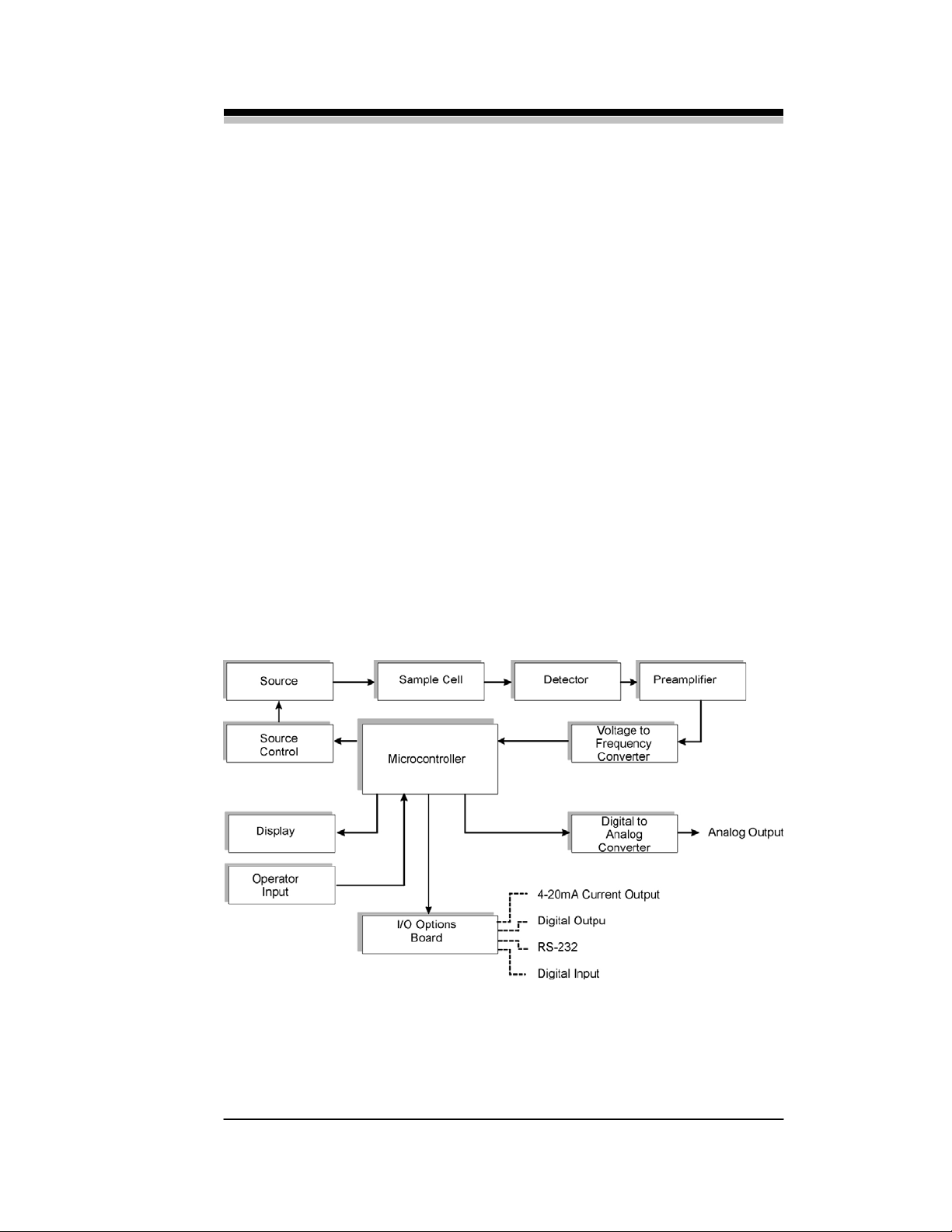
Figure 2-3 is a system block diagram which shows the functional
relationship between the electronics and the optical bench.
Figure 2-3: System Block Diagram
Teledyne Analytical Instruments., - Rev. 3 13
Page 22

Operational Theory 2 IR7000
During calibration, the microcontroller on the main board stores
information regarding zero and full span values. Specifically, the
microprocessor takes a series of consecutive readings and calculates the
difference between pairs of consecutive readings. The embedded software
analyzes the resulting differences and tests for discrepancies in the result.
The microprocessor uses this information to test for drift during
calibration.
The absolute difference between a true zero and 100% span gas is
determined at the factory and permanently stored in memory. The
software compares this value with collected data during a calibration or
measurement to determine the validity of the reading. If the calibration or
sample gas measurement falls outside a predetermined range based on the
known good values in memory, error routines are called and signals are
sent to the display board to generate appropriate messages. See Section 5
Calibration for more information.
2.3.4 Display
The display contains the 2-line 16 character vacuum fluorescent
display on the front panel. Signals are transferred to and from the main
board via a ribbon cable.
2.3.5 I/O Board
The standard I/O board is responsible for taking a analog signal from
the main board and converting it to a 0–1, 0–5 or 0–10 V analog output.
An optional 4–20 mA isolated current ouput may be installed depending
on the options selected by the customer. See Section 3.7.1.
2.4 Sample System
If a sample system is not provided by LSC, the customer will be
responsible for providing a suitable sample system. A custom sample
system can be designed and fabricated by LSC based on the particular
application. Contact Teledyne Analytical Instruments for details.
In order to achieve maximum results from the analyzer, some
consideration must be given to the sample system design. The sample
system is responsible for supplying properly conditioned sample and
calibration gases to the analyzer at a pressure and flow rate commensurate
with the analyzer. The sample system provided by the customer must be
capable of delivering clean and moisture free (non-condensing) sample to
14 Teledyne Analytical Instruments., - Rev. 3
Page 23
NDIR Gas Analyzer Operational Theory 2
the instrument with a flow rate between 0.2–2.0 liters per minute (2.0 to
5.0 liters per minute for low level optical bench) at 5 psig or less. For
samples greater than 5 psig contact factory. The sample temperature must
be in the range of -10 to 50°C (14–122)°F.
WARNING: The maximum rated pressure of the sample cell is 5 psig.
Exceeding this pressure at any time may cause the sample cell to
fail. This could result in harmful release of sample gas.
The following are items to be provided by the customer:
• Calibration gases
• Nitrogen (N
) for zero calibration
2
• Span calibration gas
Use a span gas with a concentration of the gas of
interest greater than 50% of the largest desired
measurement. The span gas should be between 10%
and 100% of the instrument’s full scale, preferably
around 80%. For example, if the largest expected
reading is 3000 ppm, then the calibration gas should be
at least 1500 ppm.
The balance of the span gas should be N2.
If the instrument has a dual optical bench (Model
IR7000B or IR7000D), the span gas must contain
calibration values for both species being measured.
If an optional oxygen (O2) sensor is installed, the span
gas must contain a calibration value for O2. If the 0–
25% O
sensor is installed, use a calibration gas
2
containing 20% O2.
• Pressure regulator, flow adjustment valves, tubing and fittings
for delivering properly conditioned sample gas to the
instrument. The sample gas pressure must be less than 5
psig. For pressures above 5 psig contact factory.
• Pressure regulator, flow adjustment valves, tubing and fittings
for delivering calibration (zero and span) gas to the instrument.
• If the automatic calibration feature is to be used, the customer
must also supply 2 solenoid valves. The split architecture
versions of this instrument are capable of handling 3 solenoid
valves. Refer to Section 3 Installation and Setup for details
regarding the installation of these components.
• The sample gas should be vented to atmospheric pressure. If the
Teledyne Analytical Instruments., - Rev. 3 15
Page 24
Operational Theory 2 IR7000
sample gas is to be returned to the process or flare, suitable back
pressure controls should be employed to ensure the analyzer vents
at a constant pressure.
2.5 Internal Gas Handling System
The gas handling system inside the analyzer is similar in principle for
all models. The following information describes the internal gas handling
system for the IR7000 model. Variations for other models will be noted.
Figure 2-4 is a diagram of the internal components and plumbing for
directing calibration or sample gas through the analyzer.
Figure 2-4: Sample Path Through Analyzer – Sta ndard Model
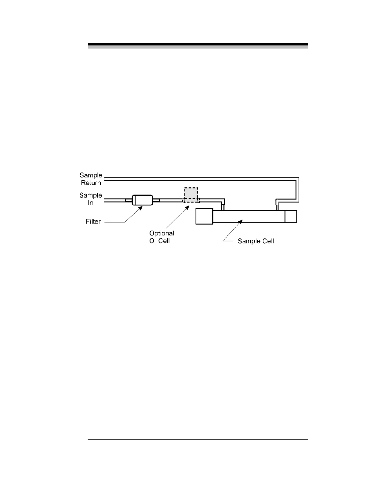
Either sample or calibration gas is delivered under pressure to the
analyzer by the customer or LSC supplied sample system. The gas enters
the analyzer and passes through a 0.3-micron disposable filter to remove
any particulate matter. If an O2 channel has been incorporated, the O
2
sensor is installed in series with the sample cell. The gas passes first
through the O2 sensor and then through the sample cell and out to the
sample return.
In the portable model, a 12V DC mini-pump is installed between the
disposable filter and the sample cell. Otherwise the internal plumbing is
the same.
The internal gas handling systems installed in the split-architecture
and explosion proof models vary according to the specific application. In
general, the plumbing is the same as the standard models with the
following exceptions:
• Metal tubing and fittings replace Teflon lined PVC tubing
16 Teledyne Analytical Instruments., - Rev. 3
Page 25

NDIR Gas Analyzer Operational Theory 2
• Stainless steel, brass or copper fittings are installed for mating
to the customer’s sample system or throughout the system for a
LSC supplied sample system.
• A different filter and a filter housing is used
NOTE: Because these models are often supplied for custom applications,
please check the front of this manual for any included Addendum
which will describe features, notes and warnings that specifically
apply to your instrument.
Teledyne Analytical Instruments., - Rev. 3 17
Page 26

Installation
3.1 Overview
Installing the Model ir7000 consists of:
• Unpacking and Inspection
• Mounting
• Gas Connections
• Electrical Connections
• Calibrating the System
3.2 Unpacking and Installation
The analyzer is shipped ready for installation. You should have
received a single carton containing the analyzer and power cord (except
230 VAC versions). If you have ordered an instrument with the optional
O2 sensor channel, the electrochemical cell will have been installed at the
factory.
Carefully unpack the instrument and inspect it for any damage or
missing components. Signs of damage would include dents, scratches,
broken glass inside the casing etc. Check that you have received the power
cord or battery charger for the portable model. Contact the shipper
immediately to report shipping damage. Contact the factory for missing
parts.
3.3 Mounting the Analyzer
The ir7000 series of analyzers are designed to be used indoors and in
a general-purpose area. The split-architecture models (explosion proof) are
designed to have the analysis unit operate in a hazardous environment
with the control unit remotely located in a general-purpose area.
The instrument must be kept dry and protected from:
• Direct sunlight
• Direct air currents which could affect the temperature of the
sensors
Page 27

NDIR Gas Analyzer Installation 3
• Shock and vibration
• Temperatures below -10° C (14°F) or above 50°C (122°F)
For maximum response, locate the instrument as close to the sample
line as possible.
The ir7000 is designed for mounting into a standard 19” instrument
rack. When mounting, make sure that there are no fans which exhaust
directly at the instrument. The IR7000B is a wall mountable unit housed in
a NEMA-4 enclosure. Both this instrument and the explosion proof model
should be anchored to a wall or special panel.
3.4 Gas Connections
The instrument requires:
• N2 for zero gas
• A suitable span gas
• Sample gas
Gas connections for sample in and sample return are made on the
rear panel. Barbed connectors are installed on the rear panel for
connection to the customer’s sample system. The IR7000P portable model
has a connector on the front panel for accepting a probe for sampling. It
has a barbed connector on the rear panel for the sample return.
In some installations where the sample take off is located some
distance from the analyzer, it may be useful to install a bypass loop with a
needle valve and flow meter just before the inlet to the analyzer. This loop
can be used to shunt a portion of the sample back to the source to decrease
the lag time of the system by increasing the total flow through the sample
system. Whatever sample system is employed, use a regulator to limit the
pressure to below 5 psig before entering the analyzer.
Once the gas connections are made, run zero gas through the analyzer
to set the flow and check for leaks. Use a flow rate commensurate with
your application. A higher flow will increase the instrument response but
care must be taken to avoid pressurization over 5 psig. For leak testing, a
commercially available soap solution is adequate for gross leak checking.
NOTE: To run gas through the sample cell on instruments using the
autocalibration feature, you must apply power to the instrument and
to energize the solenoid valves.
WARNING: If your application uses a toxic, flammable or explosive gas, use
additional leak checking methods such as a hand held gas sniffer.
Periodically, use a portable combustible gas analyzer or sniffer
around all joints and fittings.
Teledyne Analytical Instruments., - Rev. 3 19
Page 28

Installation 3 IR7000
When there are no leaks in the sample system run span gas through
and then sample gas to check the flow rates. If you are using a bypass
loop, do not set the sample or calibration regulators above 5 psig in an
effort to increase the flow.
3.5 Sample System Considerations
If a sample system is not included with the analyzer, it is the
customer’s responsibility for making available a preconditioned (noncondensing and particle-free) sample gas at 5 psig or less. The temperature
of the gas must be between -10° C (14°F) and 50°C (122°F), preferably at
the same—or close to— the temperature of the instrument.
Calibration gases (zero and span) must be tied into the sample
delivery system in such a manner that the operator, or instrument, if using
the automatic calibration feature, can easily switch from sample to
calibration gas. Standard or custom sample systems can be provided by
LSC. Contact the factory for additional information.
The sample system must be capable of maintaining a constant
pressure. If a pump is used to pull sample/calibration gas through the
system rather than delivering the sample under pressure, then care must be
taken not to induce pressure variations during the measurements or
calibrations.
WARNING: Do not allow the sample or calibration gas pressure to rise above 5
psig. The sample cell is glass(metal optional) and uses special
elastomer O-rings for sealing. At pressures above 5 psig, the cell
can fail or leak. This could result in exposure to harmful gas.
Additional warnings in the form of cautions are presented in this
manual whenever a gas connection is to be made. While cautions
are generally used to describe potential damage to the instrument
or process, the user should keep in mind the potential danger of a
gas leak and it’s effect on personnel.
NOTE: To run gas through the sample cell on instruments using the
autocalibration feature, you must apply power to the instrument and
to energize the solenoid valves.
20 Teledyne Analytical Instruments., - Rev. 3
Page 29

NDIR Gas Analyzer Installation 3
WARNING: If your application uses a toxic, flammable or explosive gas, use
additional leak checking methods such as a hand held gas sniffer.
Periodically, use a portable combustible gas analyzer or sniffer
around all joints and fittings.
• When there are no leaks in the sample system, run span gas
through and then sample gas to check the flow rates. If you are
using a bypass loop, do not set the sample or calibration
regulators above 5 psig in an effort to increase the flow.
3.6 Electrical Connections
All electrical connections to the analyzer are made on the rear panel.
Figure 3-5 shows the rear panel for the IR7000 analyzer. Other models are
similar. Electrical connections to be made at the rear panel are:
• Analog output
• O
channel output (optional)
2
• 2 solenoid valves (3 for explosion proof model)
• 4–20 mA current output (optional)
Figure 3-1: Suggested Sample System 1 (w i t h Opti o n al O2 Cell )
Teledyne Analytical Instruments., - Rev. 3 21
Page 30

Installation 3 IR7000
• Relay outputs (optional)
• Digital I/O (optional)
• RS-232 Communications port
• AC power connections
Figure 3-5: IR7000 Rear Panel
3.6.1 Analog Output
The standard model IR7000 is equipped with a single set of analog
output terminals accessible from the rear panel. The output is set at the
factory to 0–1 VDC but can be changed to 0–5V or 0–10V full scale by
moving the slides on the switch labeled “S1” on the I/O board. The switch
is located at the upper edge of the I/O board as shown in Figure 3-6. Use
the table in the figure to set the slides for the desired output voltage. A 4–
20 mA isolated or non-isolated output is also available as an option.
A second set of 0–1, 0-5, or 0-10 VDC output terminals may be
driven if the optional O2 monitoring channel is installed. If the instrument
is equipped with a dual bench, there will be 2 sets of terminals, one for
each bench.
22 Teledyne Analytical Instruments., - Rev. 3
Page 31

NDIR Gas Analyzer Installation 3
The standard output of the analyzer is a 0–1 V DC signal and
represents the concentration from 0 to full scale on the currently selected
range. The output is linear over each range as long as LINEAR is set in the
MODE menu. See Section 4.3 The MODE Menu. For example, if the
analyzer is currently set on range 2 which has been defined as 0–100 ppm
CO2, and the MODE is set to LINEAR, then the output would be:
PPM CO
IGNAL
S
2
OUTPUT
Voltage (V)
OPTIONAL 4–20 MA
OUTPUT
C
URRENT (MA)
0 0 4
10 0.1 5.6
20 0.2 7.2
30 0.3 8.8
40 0.4 10.4
50 0.5 12.0
60 0.6 13.6
70 0.7 15.2
80 0.8 16.8
90 0.9 18.4
100 1.0 20.0
I/O BOARD SWITCH POSITIONS FOR VOLTAGE OUTPUT
S1-1 S1-2 S1-3 S1-4 IR Volt O2 Volt
OFF OFF 1V.
OFF ON 5V.
ON ON 10V.
OFF OFF 1V.
ON ON 5V.
ON ON 10V.
Teledyne Analytical Instruments., - Rev. 3 23
Page 32

Installation 3 IR7000
Figure 3-6: Location of Slide Switc h S1 on I/ O Bo ard
24 Teledyne Analytical Instruments., - Rev. 3
Page 33

NDIR Gas Analyzer Installation 3
3.6.2 Analog Output Connections
Output signals from the IR section of the analyzer are available from
the 2 leftmost terminals on the long connector labeled INFRARED
CHANNEL 1. Attach the wires from the output device to the connector at
the terminals labeled VOLT OUT/IR. Make sure the proper polarity is
observed.
If an O
to monitor the O
channel is installed, connect the 2 wires from the device used
2
concentration to the terminals labeled VOLT OUT/O2.
2
Again, observe proper polarity.
If the current output option is installed, connect the 2 wires from the
current driven output device to the terminals labeled mA OUT/IR using
the indicated polarity. Repeat for the O
channel at the terminals labeled
2
mA OUT/O2.
3.6.3 Solenoid Valve Connections
To use the automatic calibration feature of this instrument a pair of
AC solenoid valves must be installed on the sample system. If not
installed by the factory, the customer is responsible for obtaining and
installing the valves into the sample system. Refer to Figures 3-1 and 3-2
for suggested placement. The solenoid valves are driven by isolated triacs.
The triacs can handle a maximum rated load of 0.6 A at instrument
voltage.
The factory recommends using 2 3-way valves to control the sample
and calibration gas flow through the analyzer. See Figure 3-1 and 3-2 for
suggested sample system valve layouts.
To install the electrical connections of the solenoid valves, refer to
Addendum “B” at the back of this manual.
The sense of the valve — flow when energized or flow when deenergized — depends of the disposition of the 3-way valve in the sample
system. The sense must be correct for your application. When the
autocalibration feature is called by the microprocessor to begin a ZERO
calibration, the solenoid connected to the terminal labeled ZERO will be
energized. The solenoid connected to the SPAN terminal will be deenergized. See Table 3-1 for the solenoid valve status during
autocalibration for the suggested sample systems given in Figures 3-1 and
3-2.
Teledyne Analytical Instruments., - Rev. 3 25
Page 34

Installation 3 IR7000
NOTE: The customer is responsible for supplying and installing the sample
system if one has not been provided by LSC. Liston cannot be
responsible for improperly designed or fabricated sample systems. If
questions arise regarding the suitability of a sample system or sample
system component, consult Customer Service for guidance.
FLOW VALVE SOLENOID
STATUS
Zero Gas A energized
B de-energized
Span Gas A de-energized
B energized
Sample Gas A de-energized
B de-energized
Table 3-1: Solenoid Status for Gas Flows
For the explosion proof and split-architecture models, provisions are
made for controlling 3 AC solenoid valves in the sample system. A similar
valve layout as shown in Figure 3-1 and 3-2 can be used for deploying 2
3-way valves for controlling calibration and sample gases. Alternatively,
one can used 3 2-way valves with a valve on each line (sample, zero and
span). See also the application shown in Figure 3-3.
Connections from the solenoid valves are made to the rear panel on
the control unit.
3.6.4 Optional Relay Outputs
AC / DC relays are available as an option on the IR7000 series of
analyzers. This option is not available for the portable model. If the
optional relays (K1, K2, K3) have been installed, the sets of connections
on the rear panel will be functional. Each relay is a single pole, double
throw relay and provides a common (C), normally closed (NC) and
normally open (NO) terminals for connection to the users equipment
(alarm lamps, annunciator, or other control, warning or recording devices.
26 Teledyne Analytical Instruments., - Rev. 3
Page 35

NDIR Gas Analyzer Installation 3
The relays are normally tied in to the high limit alarm, low limit
alarm, and failure alarm outputs during assembly. They can be coupled to
other outputs by cutting and installing jumpers on the main board. Consult
the factory for more information on altering the default relay coupled
output.
The relay outputs can be used to switch up to 1 A at 60 VDC or 30
VAC.
3.6.5 Digital I/O Option
The Digital Input/Output option provides opto-isolated digital input
and output capability for controlling functions of the analyzer.
The outputs indicate:
• The current range in use
• If a calibration is in progress
• Whether an audible alarm has triggered
• High and low limit/alarm status
• Fault alarm status
The inputs are used to:
• Initiate a zero and/or span calibration
Each output is the collector and emitter of a phototransistor. The
customer must provide a voltage to each collector and a resistor to limit
the current (100 mA maximum per device). The outputs can switch 100
mA at 25 V. See the Option Board Schematic in the Reference Section of
this manual.
The digital inputs supplied by the customer are used to drive LED’s.
The customer must supply a voltage to each LED and a current limiting
resistor. A minimum of 10 mA is required by the LED’s. Do not exceed
20 mA. The forward voltage drop is 1.5V.
The Digital I/O connector mounted on the rear panel of the
instrument is an industry standard metal shell 24 pin ribbon connector.
The contact spacing is 2.16 mm (0.085 in) center to center. The customer
must fabricate the cable and mating connector. One source for the mating
connector is Thomas & Betts Co. P/N 622-24FM.
Table 3-2 shows the pin connections for the connector mounted on
the rear panel. Table 3-3 indicates the logic used in the range selection
and identification.
Teledyne Analytical Instruments., - Rev. 3 27
Page 36

Installation 3 IR7000
PIN
#
FUNCTION
PIN
#
FUNCTION IN/OUT
1 Range Bit 0 + 2 Range Bit 0 - Output
3 Range Bit 1 + 4 Range Bit 1 - Output
5 Doing Cal + 6 Doing Cal - Output
7 Alarm/Limit 1 + 8 Alarm/Limit 1 - Output
9 Alarm/Limit 2 + 10 Alarm/Limit 2 - Output
11 Audible Alarm + 12 Audible Alarm - Output
13 Spare1+ 14 Spare1 - Input
15 Spare2 + 16 Spare2 - Input
17 Not Used 18 Not Used
19 Cal Req. Full/Zero + 20 Cal Req. Full/Zero - Input
21 Cal Req. Span + 22 Cal Req. Span - Input
23 Fault + 24 Fault - Output
Table 3-2: Digital I/O Connector Pin Out
CHART
RANGE
BIT 0 BIT 1
1 Off Off
2 On Off
3 Off On
4 On On
Table 3-3: Range ID Logic Table
Installation involves:
• Fabricate the I/O cable with mating connector.
• Mate cable and connector to the rear panel.
• Connect opposite end(s) of cable to the input and output devices.
3.6.6 RS-232 Cable
An optional serial port is available for communication to and from a
remote computer. The port is a standard RS-232 serial communications
port and allows the user to input control functions and output data in
response to a variety of requests. A standard DB-9 male connector is
mounted on the rear panel for connection to a remote PC computer via a
28 Teledyne Analytical Instruments., - Rev. 3
Page 37

NDIR Gas Analyzer Installation 3
Null Modem cable. The pin assignment for the DB-9 connector is shown
in Figure 3-7.
The RS-232 communication parameters are fixed at:
Parameter Setting
Baud 2400
Byte 8 bits
Parity none
Stop Bits 1
The description of the RS-232 communication protocol is given in
the Appendix.
Figure 3-7: RS-232 Pin Assignment
3.6.7 Power Connections
The IR7000 is shipped configured for 120 or 230 VAC operation.
After all other electrical and gas connections have been made,
connect the AC power to the power entry module on the rear panel.
The analyzer can now be powered up for testing gas connections,
solenoid operation and internal functions through the power-on self
diagnostic test.
If the instrument successfully powers up with no error messages and
there are no gas connection or solenoid activation problems, the analyzer
Teledyne Analytical Instruments., - Rev. 3 29
Page 38

Installation 3 IR7000
can be configured for operation using the SETUP and MODE buttons on
the front panel. Refer to Section 4 for entering SETUP and MODE
parameters.
30 Teledyne Analytical Instruments., - Rev. 3
Page 39

Operation
4.1 Overview
There are 4 steps involved in operating the IR7000 NDIR Gas
Analyzer:
1. Initial warm up—the analyzer must be powered up and
stabilized before introducing a sample for analysis. The
optimum warm up time is 3 hours although the instrument can
be used after 1 hour.
2. Configuring the instrument for your application using the
SETUP function. This can be done during the warm-up period
if desired.
3. Setting operational parameters via the MODE function.
4. Calibrating the instrument with zero and then span gas. Section
5 describes calibration in detail.
4.2 The SETUP Menu
Once the analyzer has been installed, gas lines connected and
electrical connections made, the IR7000 can be configured for your
application. Refer to Section 3 for installation procedures. Configuring the
instrument involves:
• Entering span gas concentration(s)
• Activating automatic calibration function and frequency
• Setting chart recorder or output ranges
• Entering alarm set points
• Selecting Cal Delay (flush time)
These parameters are entered into the instrument by accessing the
SETUP menus from the front panel. See Figure 4-1. They can be entered
in any order.
To enter setup information into the instrument press and hold in the
SETUP button. This brings you to the 1st SETUP submenu. Make your
selection between the available options, or change the value for that
Page 40

Operation 4 IR7000
submenu using the UP (Δ) or DOWN (∇) buttons To access the next
submenu within the SETUP menu, release the SETUP button then press
the SETUP button again. This cycles through the submenus one at a time.
To configure the instrument for your application, follow the steps
outlined below.
CAUTION: Make sure that the power cord is attached and the instrument is
properly grounded. Make sure that there are no leaks in the
sample system.
Ensure that the inlet pressure of the sample gas is less than 5
psig and stable.
Figure 4-1: SETUP and MODE Menus
SETUP MODE
Cal Gas Calibrate
Full Auto Chart =
Range (1-4) Filter =
Alarm L Calibration Hold/Track
Alarm H Linear/Non linear
Cal Delay Bright =
O2 Cal Gas Alarm = On/Off
Auto = Full/Zero
32 Teledyne Analytical Instruments., - Rev. 3
Page 41

NDIR Gas Analyzer Operation 4
1. TURN ON THE PO WER
The instrument will initiate a power-on self-diagnostic test.
It will briefly display the initial start-up messages. If the
self-test is successful, the first message will indicate that a
battery backup memory fetch was successful and any
previously saved configuration settings will be retrieved
and set as the current configuration. If this configuration is
the desired setup for your analysis session, go to Section
4.3 MODE Menu. If this is the first session or you need to
edit any or all of the configuration settings, continue on
with step 2. The next start-up screen which automatically
appears on the display identifies the model and serial
number of the instrument. This screen will be followed by a
third screen which identifies the US patent number of the
instrument and software version installed. Finally the
analysis screen will appear with a display as shown in
Figure 4-3 and the example screen on the left. The analysis
screen indicates:
• The gas of interest (CO2 in the example screen)
• An initial reading (ignore this for the present time)
• R:1 — analog range (range 1 for this example)
• LINEAR—indicating that the indicated gas
concentration has been linearized before being
displayed.
• f:100 — indicating the amount of filtering being
applied to the measurement. See Section 2.3.3.
NTER THE SPAN GAS CONCENTRATION
2. E
Press and hold the SETUP button to enter the CALGAS
submenu.
The CALGAS submenu allows you to specify the
concentration of your span gas. Note that you cannot
change the span gas, only the concentration of the gas.
NOTE: You must continue to hold in the SETUP button while you edit or enter
information into the display. Releasing the SETUP button will take you
back to the ANALYSIS screen. Pressing the SETUP button again will
cycle you to the next submenu item in the SETUP menu. In order to
get back to the menu you were working in, cycle through all 5 or 6
(depending on the model) submenus.
Teledyne Analytical Instruments., - Rev. 3 33
Page 42

Operation 4 IR7000
The sequence of submenus available from the SETUP main menu are
as follows:
SUBMENU DESCRIPTION
CAL GAS Enter concentration of span gas
FULL AUTO
Set automatic calibration “ON” or “OFF”
And time span between auto-calibrations
Chart 1 Set upper bound of analysis range 1.
Chart 2 Set upper bound of analysis range 2.
Chart 3 Set upper bound of analysis range 3.
Chart 4 Set upper bound of analysis range 4.
Alarm L Set Alarm 1 threshold (LOW alarm).
Alarm H Set Alarm 2 threshold (HIGH alarm).
Set delay between request for calibration and
CAL DELAY
actual start of calibration. Used to purge cell
before calibrating.
O2 CAL GAS
If present, enter concentration of O2 span
gas.
• Enter the Span Gas Concentration. Use the UP and
DOWN arrows on the front panel while holding in the
SETUP button to change the actual concentration of
your span gas. The value on the lower right of the
screen will change as you press either arrow. Note that
after 10 units up or down, the longer you hold in an
arrow, the faster the value changes. Stop when you are
close to the correct concentration for your span gas and
then resume by pressing the UP (Δ) or DOWN (∇)
arrow again for the final slow approach to the correct
value.
• Save the changes. The SAVE or LOSE screen will
automatically appear when you release the SETUP
button. It will prompt you to press Δ or ∇ to save or
lose the changes. You have 60 seconds to either save or
discard your changes. The default value is discard.
When the changes are discarded, either the default
instrument values or the last saved values will be set.
34 Teledyne Analytical Instruments., - Rev. 3
Page 43

NDIR Gas Analyzer Operation 4
3. ENTER AUTOMATIC CALIBRATION FREQUENCY (If enabled)
between automatic calibrations. Automatic calibrations
requires that the analyzer be connected to externally powered
solenoid valves. The type of automatic calibration (either zero
or full) is selected in the MODE menu.
NOTE: In a dual analyzer this menu selection will not appear
in the second IR channel (referred to as “slave”) and is also
not present in the battery portable model.
Press and hold the SETUP button to enter the number of hours
4. DEFINE RANGES
Press and hold the SETUP button to enter the Range 1
submenu. If necessary, cycle through the submenus by
repeatedly pressing the SETUP button until the CALGAS
menu appears. Then press and hold the SETUP button once
more to enter the CHART 1 submenu.
NOTE: The dynamic range of the IR7000 detector is 1000:1 which means
that it can respond to a 1 PPM change in a sample containing 1000
PPM. This is fixed by the design of the detector and is independent of
the range setting. The 4 user definable ranges are implemented
mainly to accommodate standard output devices such as chart
recorders. The full output 0–1V, 0–5V or 0–10V (or optionally, 4–
20mA) will be linearly scaled over the defined chart range.
• Enter Range 1. Use the UP and DOWN arrows on the
front panel while holding in the SETUP button to enter
or change the upper bound of the CHART 1 range.
NOTE: The 4 user definable ranges must be consecutively increasing. That
is, the upper bound on each successive range must be greater than
the previous range’s upper bound. Range 4
Range 1.
≥
Range 3 ≥ Range 2 ≥
• Save changes. As before, once you release the SETUP
button you will be prompted to save or else lose any
changes you made. There is a 60-second timer on this
screen. Press the UP button to save your changes or the
DOWN button to discard the changes within the 60second time limit. A confirmation screen will then
appear.
• Set the other ranges. If desired, toggle to the next
submenu (CHART 2) and continue in a similar fashion
Teledyne Analytical Instruments., - Rev. 3 35
Page 44

Operation 4 IR7000
until all 4 ranges have been defined. It is not necessary
to set all 4 ranges in order to use the instrument.
5. ENTER ALARM SETPOINTS
The next 2 submenus allow the user to enter low and high
alarm setpoints respectively. Press and hold the SETUP button
until the ALARM L submenu appears. If necessary, cycle
through the submenus by repeatedly pressing the SETUP
button until the CHART 4 menu appears. Then press and hold
the SETUP button once more to enter the ALARM L submenu
for editing.
• Enter the low alarm setpoint. Use the UP and DOWN
arrows on the front panel while holding in the SETUP
button to enter or change the low alarm setpoint. An
alarm setpoint of 0 turns the alarm off. The OFF status
or the setpoint will be reflected on the bottom line of
the display.
• Save changes. Again, after releasing the SETUP
button, you will be prompted to save or else lose any
setpoint changes you made. There is a 60-second timer
on this screen. Press the UP button to save your
changes or the DOWN button to discard the changes
within the 60-second time limit. A confirmation screen
will then appear.
• Enter the high alarm setpoint. Go to the next
submenu (ALARM H) to set the high alarm setpoint.
Use the UP and DOWN arrows on the front panel while
holding in the SETUP button to enter or change the
high alarm setpoint. As before, an alarm setpoint of 0
turns the alarm off.
NTER CALIBRATION DELAY TIME
6. E
The next submenu, CAL DELAY, is used to specify the time
delay before the start of a calibration. The time delay begins
when the calibration is requested either manually or through
the autocalibration feature. During the delay, the sample cell
should be purged with zero or span gas depending on the
particular calibration.
36 Teledyne Analytical Instruments., - Rev. 3
Page 45

NDIR Gas Analyzer Operation 4
Without this delay, or if the delay is set too short, it is possible to
generate calibration errors. In most cases the instrument will
attempt to recalibrate. After 5 recalibration attempts the
instrument will generate a LOW CALIB FLOW ALARM. If
this occurs, see Section 6.3.1.
NOTE: The CAL DELAY submenu is not present on the battery operated
portable instrument.
NOTE: Autocalibration is not available on the battery operated portable
model.
• Set calibration delay time. Use the UP and DOWN
arrows on the front panel while holding in the SETUP
button to enter or change a delay period.
• Save changes. After entering a value and releasing the
SETUP button, you will be prompted to save or else
lose the changes you made. There is a 60-second timer
on this screen. Press the UP button to save your
changes or the DOWN button to discard the changes
within the 60-second time limit. A confirmation screen
will then appear.
To determine the optimum delay time, initiate a manual
span calibration (see Section 5 Calibration) and while
watching the display, note the time it takes to reach a
stable span calibration reading. Add 10% to this reading
and use this value for the CAL DELAY.
NOTE: In models with dual optical benches, the CAL DELAY value must be
the same for both channels.
When performing a manual calibration, if the
calibration flow has already been established and stable
readings exist, set the CAL DELAY to 15 seconds (60
seconds for trace instruments).
During the calibration event, if the instrument detects a
change in the gas concentration, it will automatically
attempt to recalibrate. This could occur for example, if
there is a leak in the sample system upstream of the
detector. If after 5 attempts at calibration the system
still detects an unstable concentration, a LOW CALIB
FLOW alarm will be indicated on the display. If this
occurs, refer to Section 6.3.1.
Teledyne Analytical Instruments., - Rev. 3 37
Page 46

Operation 4 IR7000
7. ENTER THE O
SPAN GAS CONCENTRATION
2
Press and hold the SETUP button to enter the O2 CAL GAS
submenu.
NOTE: The O2 analysis feature is an option and not present on all models.
On instruments without this feature, there will not be an O2 CAS GAS
screen.
• Input the O2 span gas value. Use the UP and DOWN
arrows on the front panel while holding in the SETUP
button to enter the actual concentration of your span
gas. The value on the lower right of the screen will
change as you press either arrow.
• Save changes. Again, after releasing the SETUP
button, you will be prompted to save or else lose any
setpoint changes you made. There is a 60-second timer
on this screen. Press the UP button to save your
changes or the DOWN button to discard the changes
within the 60-second time limit. A confirmation screen
will then appear.
38 Teledyne Analytical Instruments., - Rev. 3
Page 47

NDIR Gas Analyzer Operation 4
4.3 The MODE Menu
Operational parameters of the analyzer are established through the
MODE menu. From the MODE menu you can:
• Initiate a calibration (zero, span, or both).
• Set which user-defined or default chart range to use, or let the
instrument select the range automatically using the autoranging feature.
• Select the amount of filtering to be applied to the measurement.
• Select whether the instrument tracks the gas reading during a
calibration or holds the last reading prior to the calibration
cycle.
• Select whether the readings are linearized or nonlinearized.
• Set the contrast of the display.
• Toggle the alarm feature on or off.
• Select either a full (zero and span) or zero only automatic
calibration.
The MODE submenus are displayed and their functions are set in the
same manner as the SETUP features were: hold in the MODE button and
use the UP and DOWN button to select the appropriate value or selection.
Releasing the MODE button and pressing it again brings you to the next
submenu. Figure 4-1 shows the MODE submenus in the order in which
they will appear on screen.
ALIBRATE
1. C
The first submenu of the MODE menu is the CALIBRATE
submenu. It allows the operator to initiate a calibration event.
The operator can select either a zero, span or full calibration
(zero and span). The calibration event will begin after a delay
as defined in the SETUP/CAL DELAY submenu. See Section
4.2 SETUP Menu and Section 5 Calibration.
• Select the calibration event. Press the UP button
(UPS) to select a span calibration. Press the DOWN
button (ZRO) to select a zero calibration. Press the
SETUP button to select a full calibration (both zero and
span).
Teledyne Analytical Instruments., - Rev. 3 39
Page 48

Operation 4 IR7000
NOTE: Select FULL only when properly setup for performing automatic
calibration. See Section 3 Installation. The FULL selection is not
available on the battery operated portable model.
The calibration will initiate after releasing the UP or
DOWN arrows subject to the calibration delay period
which was entered in the CAL DELAY submenu
during SETUP.
NOTE: In the battery portable model, manually switch over to zero or span
calibration gas to purge the sample cell before pressing the UP or
DOWN buttons.
The screen will indicate which calibration is to be
performed and then change to the countdown screen
indicating the time remaining in the CAL DELAY
function. The time remaining is shown in the upper left
of the display and “delay” is indicated at the lower
right. The concentration of the gas in the sample cell is
also displayed on the top row.
NOTE: To optimize the CAL DELAY function, you can initially set the CAL
DELAY function to some high value, for example 120 seconds. Refer
to Section 4.2 for setting the CAL DELAY period. Then, time the
calibration while observing the display as it changes. Note the time in
seconds it takes for the concentration reading to stabilize. Add 10% to
this value and reenter it into the CAL DELAY submenu of the SETUP
menu.
After the CAL DELAY period has elapsed, the
calibration begins. Data is collected and averaged over
20 seconds. If an unstable reading is obtained, the
instrument will automatically recalibrate for another 20
seconds. The instrument will attempt a recalibration up
to 5 times and if it cannot find a stable calibration value
it will either restore the old calibration value or enter
into an alarm mode. See Section 6.3.1 for alarm
messages and procedures.
2. SELECT CHART RANGE
The next submenu is used to select the chart output range the
instrument will use during analysis. The ranges can be userdefined however the instrument will default to standard ranges
preset at the factory if no user-defined ranges have been setup.
See Section 4-2 for information on how to set up the chart
ranges. The analyzer is equipped with an autoranging feature
which will automatically select the correct chart range during
the measurement.
40 Teledyne Analytical Instruments., - Rev. 3
Page 49

NDIR Gas Analyzer Operation 4
• Enter the desired range or select autorange. Press
the MODE button repeatedly until you reach the
CALIBRATE? submenu. Press and hold the MODE
button one more time to lock onto the CHART
submenu.
There are 2 mutually exclusive choices to make from
this submenu: FIXED range or AUTO. If you are using
a FIXED range, the top line of the display will indicate
the currently selected range (1–4). See the example
screen on the left. When FIXED is in effect, you can
change to the next range by pressing the UP button or
enter the AUTO mode by pressing the DOWN button.
If AUTO range is selected, the display will indicate
AUTO. You can change back to FIXED range by
pressing the DOWN button. Pressing the UP button will
also place you in FIXED mode and will select the range
indicated on the lower left in the display.
3. FILTER
The FILTER submenu allows the operator to choose the
amount of filtering that is applied to the measurement. There
are 3 filter settings available: 1, 10, 100 (10, 100, 1000 for
trace instruments). The response time of the analyzer is related
to the filter number. Choosing a lower filter number results in a
faster response, however higher filtering yields a smoother
measurement.
• Enter a filter value. Press the MODE button
repeatedly until you reach the CHART submenu. Press
and hold the MODE button one more time to lock onto
the FILTER submenu. Use the UP or DOWN arrows to
toggle through the available filter settings. The filter
value will be indicated on the top line of the display.
Releasing the MODE button will set the filter value.
Teledyne Analytical Instruments., - Rev. 3 41
Page 50

Operation 4 IR7000
4. CAL TRACK OR HOLD
The TRACK/HOLD submenu selection determines how the
display and output signal behave during a calibration. If
TRACK is selected, the output signal and display will change
with the measured value of the gas during calibration. If HOLD
is selected, the output signal and display will remain fixed at
the last measurement prior to the calibration.
• Select Cal TRACK or HOLD. Press the MODE button
repeatedly until you reach the FILTER submenu. Press
and hold the MODE button one more time to lock onto
the CAL=TRACK/HOLD submenu. Initially, the
default setting of HOLD is set and displayed on the
screen. Use the UP arrow to toggle between TRACK
and HOLD. Releasing the MODE button enters the
selection displayed on the screen.
NOTE: If the instrument is set to CAL = HOLD, there will be no change in
display or output of the calibration value, it will hold on the last
measured value before the calibration command was given. At the
end of the calibration event, there will be another delay in output
equal to the CAL DELAY period while the gas concentration in the
sample cell changes from pure calibration gas to actual sample g as. If
the calibration has changed since the last calibration, there will be a
jump in the reading as the new calibration takes effect. See Figure 4-
3.
If the instrument is set to CAL = TRACK, the display and output will
change as the gas concentration changes. At the end of the
calibration event, there will NOT be a another delay in output equal to
the CAL DELAY period. The display and output will show the
changing gas composition as the cell adjusts itself from calibration
gas to actual sample. If the calibration has changed since the last
calibration, jump in the reading as the new calibration takes effect.
See Figure 4-4.
42 Teledyne Analytical Instruments., - Rev. 3
Page 51

NDIR Gas Analyzer Operation 4
Figure 4-3: Output Jump After New Calibration, CAL=HOLD
Figure 4-4: Display & Output Jump After New Calibration,
CAL=TRACK
Teledyne Analytical Instruments., - Rev. 3 43
Page 52

Operation 4 IR7000
INEAR/NONLINEAR MODE
5. L
The choices in this submenu effect whether the output data
(display and output) are linearized or not. For accurate
readings, it is recommended that you leave this function set to
LINEAR.
• Set Linear or Nonlinear Data. Press the MODE
button repeatedly until you reach the CAL
TRACK/HOLD submenu. Press and hold the MODE
button one more time to lock onto the
LINEAR/NONLINEAR submenu. Use the UP arrow to
toggle between the LINEAR and NONLINEAR setting.
If you choose NONLINEAR, you have the additional
option of selecting either PPM or counts as the
displayed units of measure. Use the UP and DOWN
arrows to select the desired units. Releasing the MODE
button will bring back the analysis screen which reflects
your data mode choice and the units of measure. See
the example screens on the left.
6. D
ISPLAY BRIGHTNESS
The relative brightness of the vacuum fluorescent display is
adjustable over 4 levels using the BRIGHT submenu.
• Select the display brightness. Press the MODE button
repeatedly until you reach the LINEAR/NONLINEAR
submenu. Press and hold the MODE button one more
time to lock onto the BRIGHT submenu. Use the UP or
DOWN arrows to toggle through the 4 levels (0–4) of
brightness settings. The display will immediately
respond to your selection.
44 Teledyne Analytical Instruments., - Rev. 3
Page 53

NDIR Gas Analyzer Operation 4
7. ALARM OFF/ON
The high and low alarms may be toggled ON or OFF by the
operator.
• Set alarm status. Press the MODE button repeatedly
until you reach the DISPLAY submenu. Press and hold
the MODE button one more time to lock onto the
ALARM submenu. Use the UP arrow to turn the alarms
ON or OFF.
WARNING: It is not recommended that you operate this instrument with the
alarms defeated. This function is implemented primarily for
maintenance convenience. If the application in which this
instrument is to be used involves the monitoring and/or control
of a dangerous gas, switching the alarm status to OFF can
seriously impair the instrument to perform its function of
warming or controlling a potentially hazardous situation.
8. AUTO FULL/ZERO
Automatic calibrations can be selected to be either zero
only or zero and span.
• Use the “up” arrow button to select either a zero or full
(zero and span) automatic calibration at the intervals
selected in the SETUP menu under FULL/AUTO.
Teledyne Analytical Instruments., - Rev. 3 45
Page 54

Calibration
5.1 Overview
This section of the manual describes the calibration process and
issues relating to calibration. Next to sample system problems, calibration
is the single most important item relating to the proper performance of
your analyzer. A properly calibrated instrument will produce accurate and
repeatable measurements of the gas of interest across the entire instrument
range.
To calibrate the instrument, you will need:
• A zero gas (preferably nitrogen)
• A span gas which contains the gas of interest at a concentration
greater than 50% of the full instrument range (preferably 80%)
• A means of appropriately switching from sample gas to
calibration gas (2 solenoid valves if using the automatic
calibration feature).
5.2 Typical Sample System
Two typical piping diagrams for the IR7000 are shown in Figure 5-1.
The explosion proof models can use a similar sample system and can
control up to 3 solenoid valves. The sample system for the explosion proof
models is housed separately in an explosion proof housing with the
electronics and controls remotely located in the control section up to 300
feet away. A specific application is shown in Figure 3-3.
Either of these configurations allows the user to control the input
stream to the analyzer with only 2 3-way valves. When flowing calibration
gas, some means must be provided for bringing the zero or span gas to the
same pressure and flowrate as the sample gas to avoid any flow induced
variables which could affect the calibration. It is highly recommended that
the calibration gas sources use a regulator and flow control device (inline
needle valve or flow meter with integral needle valve).
Figure 5-1A & B: Flow Diagram for Manual Calibration
Page 55

NDIR Gas Analyzer Calibration 5
CAUTION: The inlet gas pressure must be less than 5 psig. Do not exceed
5 psig. The sample cell is not designed to withstand
pressurization in excess of this. Make sure there are no kinks,
tight bends, or other obstructions in the sample system that
could generate excessive backpressure.
The standard models are equipped with an automatic calibration
feature which allows zero, span, or both calibrations to be performed
automatically. The user can also select the frequency of automatic
calibration. See Section 4.2 for details in setting up the instrument for
preprogrammed calibration events.
5.3 Manual Calibration
It is possible to manually calibrate the instrument at any time even if
an auto calibration period has been set. In order to obtain a valid
calibration, the sample cell must be purged of sample gas. This is
conveniently handled by having an appropriate CAL DELAY value
configured into the instrument via the SETUP function. See Section 4.2
SETUP Menu, for procedures involved in setting the CAL DELAY.
With an appropriate CAL DELAY set, make sure that the calibration
source pressure is the same as the sample gas pressure and less than 5
psig.
NOTE: The pressure in the sample cell during calibration must be the same
as when flowing sample gas. Both the IR detector and the optional
oxygen sensor are sensitive to significant pressure or flow variations.
5.3.1 Manual Zero Calibration
A manual zero calibration involves:
1. Stopping the sample flow and switching to zero gas
2. Purging the sample cell with zero gas
3. Using the CALIBRATE?/ZERO submenu of the MODE menu
to request a manual zero calibration.
To manually zero calibrate the analyzer:
• Referring to the flow diagram in Figure 5-1A, manually switch
the 3-way valve from sample gas to ZERO gas. Make sure that
valve B is set to flow gas in the position shown in the inset.
• While watching the flowmeter, use the needle valve to adjust
the flow to 1.5 SCFH or to the same flowrate that is used for
sample gas.
Teledyne Analytical Instruments., - Rev. 3 47
Page 56

Calibration 5 IR7000
• Using the MODE button, navigate to the CALIBRATE?
submenu and while holding in the button, press the DOWN
button to initiate a zero calibration.
• After the CAL DELAY period the instrument will go into
calibration mode and the display will read “DOING ZERO
CAL”. Calibration data will be collected for 20 seconds.
• After the 20 second calibration, if a manual span calibration is
to follow, switch valve A to sample gas and valve B to SPAN.
Otherwise, switch valve A to sample gas and leave valve B in
the position shown in the inset. This will allow the sample gas
to flow.
At this stage, the composition of the gas in the sample cell is
pure zero gas. Purge the cell by allowing span or sample gas to
flow for a sufficient time.
NOTE: If the TRACK/HOLD function has been set to HOLD (see section 4.3),
then there will be no change in the screen display and the output will
remain fixed on the last reading taken before entering the calibration.
At the end of the 20-second calibration there will be another delay
equal to the time delay set in CAL DELAY. This delay is used to allow
sample gas to purge the sample cell of zero gas before the instrument
resumes monitoring. It is important to close the zero gas valve and
open the sample gas valve during this delay to ensure sufficient
purging has occurred before monitoring is resumed.
If a problem is encountered during calibration and the instrument
cannot calibrate, the data from the last successful calibration will be
restored, if possible. A series of messages will be displayed on the screen
informing the user why the calibration failed and if the old values have
been restored. See Section 6 Maintenance.
CAUTION: This analyzer will zero calibrate to almost any gas. It will even
zero calibrate to your sample or span gas! If the wrong gas is
used for zero calibration, it is almost certain that the instrument
will fail in span calibration and/or generate unusable data. Make
absolutely certain that zero gas is flowing in the cell during the
zero calibration by double checking the valve status and
watching the flow meter on the front panel.
5.3.2 Manual Span Calibration
CAUTION: It is important to use a valid SPAN gas for calibration. The
concentration of the span gas must be greater than 50% of the
full range of the instrument, preferably 80%.
48 Teledyne Analytical Instruments., - Rev. 3
Page 57

NDIR Gas Analyzer Calibration 5
A manual span calibration is similar to the manual zero calibration. It
involves:
1. Stopping the sample flow and switching to span gas
2. Purging the sample cell with span gas
3. Using the CALIBRATE?/UPS submenu of the MODE menu to
request a manual span calibration.
NOTE: Before span calibration can be performed, the correct concentration of
the span gas must be entered in the SETUP/CALGAS submenu. If
this value has been previously entered it will be recalled during
startup. You will not need to reenter it unless the memory backup
failed.
To SPAN calibrate your instrument manually:
• Referring to the flow diagram in Figure 5-1B, make sure that
the 3-way valve labeled A is set to flow SAMPLE gas.
Manually switch valves B to flow SPAN gas.
• While watching the flow meter, use the needle valve to adjust
the flow to 1.5 SCFH or to the same flowrate that is used for
sample gas.
• Using the MODE button, navigate to the CALIBRATE?
submenu and while holding in the button, press the UP button
to initiate an upscale (UPS) span calibration.
• After the CAL DELAY period the instrument will go into
calibration mode and the display will read “DOING UPS
CAL”. Calibration data will be collected for 20 seconds.
• After the 20 second calibration, close the span gas valve and
open the sample gas valve to reinstate the sample gas flow. At
this stage, the composition of the gas in the sample cell is pure
span gas. Purge the cell by allowing span or sample gas to flow
for a sufficient time.
NOTE: If the TRACK/HOLD function has been set to HOLD (see section 4.3),
then there will be no change in the screen display and the output will
remain fixed on the last reading taken before entering the calibration.
At the end of the 20-second calibration there will be another delay
equal to the time delay set in CAL DISPLAY. This delay is used to
allow sample gas to purge the sample cell of span gas before the
instrument resumes monitoring. It is important to close the calibration
gas valve and open the sample gas valve during this delay to ensure
sufficient purging has occurred before monitoring is resumed.
Teledyne Analytical Instruments., - Rev. 3 49
Page 58

Calibration 5 IR7000
If a problem is encountered during calibration and the instrument
cannot span calibrate, the data from the last successful calibration will be
restored, if possible. A series of messages will be displayed on the screen
informing the user why the calibration failed and if the old values have
been restored. See Section 6 Maintenance.
5.4 AUTO Calibration
The IR7000 has a built-in auto calibration routine. To use this
feature, the user must install a solenoid valve on each of the calibration
gas sources. Electrical connections for the solenoid valves are made on the
rear panel at the Zero and Span Valve terminals. See Section 3 for
installation instructions.
The calibration sequence is handled automatically but certain
parameters must be set up for the feature to work properly.
NOTE: It is necessary to perform a MANUAL CALIBRATION at least once
prior to using the AUTO CALIBRATION feature for the first time. This
is to establish an “appropriate” CAL DELAY period. The default value
for CAL DELAY is known to be invalid for many applications. It, in all
likelihood, is not the optimum value for your setup. You must run a
MANUAL CALIBRATION to determine the proper delay period. See
Section 4-2 for instructions in determining the optimum CAL DELAY
value.
• Enter an appropriate CAL DELAY in the
SETUP/CALDELAY.
NOTE: Without an appropriate CAL DELAY period, the calibration data will
most likely be invalid since the sample cell would not have been
properly purged.
• Make sure that the proper concentration for the span gas being
used has been entered into the SETUP/CALGAS submenu.
• If an O2 channel is present, make sure that the concentration of
the O2 bearing span gas has been entered into the SETUP/O2
CALGAS submenu.
• If periodic calibration is desired, enter the type of calibration
(ZERO or FULL), and the number of hours between
calibrations in the SETUP/CAL TIME submenu.
NOTE: Setting the time to 0 turns the autocalibration feature off.
50 Teledyne Analytical Instruments., - Rev. 3
Page 59

NDIR Gas Analyzer Calibration 5
• Set whether the display and output should TRACK the data
while calibrating or HOLD the last value before the calibration.
This is done in the MODE/CAL menu. See Section 4.3.
Choosing HOLD institutes a CAL DELAY before and after the
ZERO and SPAN calibrations. This is to allow for adequate
purging of the sample cell. At the end of the SPAN calibration,
the instrument will send a signal to the span gas valve to close.
If you select TRACK, make sure that you allow a period of
time after calibration for the concentration to readjust as
sample gas replaces the calibration gas in the cell. You can
determine what is an “adequate” time by watching the display
as it changes to reflect the dynamic conditions within the cell.
• The instrument is now set to automatically calibrate at the
frequency entered into the CAL TIME submenu.
NOTE: The priority in the timing chip is low for the CAL TIME feature. Thus
the actual time between calibrations maybe different than the
specified value in CAL TIME.
5.5 Calibration Issues
• Pressure or flow variation
The detection process inherent in the patented dual chamber
balance detector essentially involves a “counting” of the
molecules of the gas of interest within the sample cell. Any
pressure or flow variation changes the instantaneous number of
gas molecules in the fixed volume cell and hence causes a span
error proportional to the pressure variation.
• Obtaining a valid difference between ZERO and SPAN
The absolute count from a given concentration of the gas of
interest will vary with time but the difference (delta) between
the zero level and same level will remain essentially constant.
Thus the need to get a valid difference between zero and span
is crucial.
In principle, the detector will zero on almost any gas however,
in practice a true zero gas such as dry nitrogen with minimum
absorption in the IR spectrum is used. Using any other gas as a
ZERO gas may cause calibration errors.
At the factory, during initial setup and calibration, a valid delta
is established using dry nitrogen and an appropriate span gas
for the application at hand. When the instrument is first
Teledyne Analytical Instruments., - Rev. 3 51
Page 60

Calibration 5 IR7000
linearized at the factory, a maximum delta using a full span gas
(100%) is determined and permanently burned into memory.
This value is used to compare subsequent readings (real or
calibration) to determine if:
A) The reading is real and not an anomaly.
B) In the case of a calibration, the calibration yielded valid
data i.e. the delta obtained is within 30% of the maximum
delta determined at the factory. If not, a calibration alarm
message is displayed and the old calibration values are
restored. See Section 5.4.
• Drift
During calibration, approximately 40 readings are taken in 20
seconds. The imbedded software looks at the difference of 39
pairs of successive readings i.e. reading #1 – reading #2,
reading #2 – reading #3 etc., and analyzes these successive
pairs in terms of their spread about 0. If the system is stable as
it should be during calibration, then theoretically, these
readings should all be 0 or close to it although there may be
some spread about 0. If the number of pairs that are increasing
are seriously out of balance with the number that are
decreasing, the software generates an error depending on the
nature of the imbalance. If the number of increasing values is
much greater than the number of decreasing values, the
software will assume that the system is drifting. It will
immediately reset and attempt to recalibrate. There will be a
maximum of 5 attempts at recalibration before an alarm
condition is displayed and the system restores the old
calibration values.
In this case, you may receive an “IR LOWFLOW FAIL”
alarm. Most often, this is due to an insufficient purge of the
sample cell prior to calibration. Increase the CAL DELAY time
significantly and try again.
NOTE: If an alarm condition is encountered, the alarm latches in the sense
that the message will only go away when the condition is corrected
AND the alarm is acknowledged. Correcting the conditions of the
alarm only will NOT clear the alarm message. Acknowledging the
alarm only will NOT clear the alarm. YOU MUST DO BOTH! To
acknowledge any alarm, press the UP button on the front display.
52 Teledyne Analytical Instruments., - Rev. 3
Page 61

Maintenance
The information in this section is to be used by qualified service
trained personnel only. To avoid injury, do not perform any service or
maintenance procedure described in this section unless you are properly
trained.
6.1 Scheduled Maintenance
The IR7000 does not require any periodic maintenance beyond
normal cleaning and filter replacement. In cases where the analysis is
performed on a hazardous gas, a routine leak checking procedure should
be adopted.
6.1.1 Cleaning
To clean the exterior surface of the analyzer, use a mild solution of
soap and water and apply with a dampened cloth. Do not use solvents. Do
not spray or apply any liquid directly onto the case or front panel.
6.1.2 Particle Filter
The sample path in some versions of the IR7000 is equipped with a
disposable 0.3-micron particulate filter. This filter is not meant to be the
primary sample filtering device. If the primary sample filter fails this
filter may become clogged. This will increase the backpressure inside the
system and reduce the flowrate. The filter should be checked periodically
and replaced as necessary.
To replace the particulate filter:
WARNING: Depending on the sample system used, sample gas may be still
flowing in the sample lines. Make sure that the sample gas is turned
off before beginning this procedure.
• Flush the instrument lines with nitrogen for 15 minutes.
• Turn off the instrument and disconnect the power cord. It is
recommended that you install a lock-out device so that the
instrument cannot be powered back up unless the lock-out
device is removed.
Page 62

Maintenance 6 IR7000
• Remove the screws securing the case and remove slide the case
off the analyzer.
WARNING: Hazardous voltage exists inside. Make sure that the instrument is
OFF and the AC power cord has been removed from the AC power
source.
• Locate the particle filter (see Figure 6-1).
Figure 6-1: Particle Filter Location
NOTE: The filter must be installed in the proper orientation. There is an arrow
on the filter indicating the direction of flow. Before removing the gas
lines, identify the inlet and exit ends of the lines for proper
reinstallation.
• Remove the PVC tubing from the ends of the filter while the
filter is still attached to the frame.
• Loosen the holding clamp and remove the filter.
WARNING: Depending on your application, the filter may contain hazardous
materials. Adhere to all local, state and federal regulations
regarding the disposal of contaminated waste.
• Insert the replacement filter into the holding clamp noting the
proper flow direction. Tighten the clamp to secure the filter to
the frame.
• Reattach the tubing ends onto the filter.
• Replace the cover and secure it with the screws.
• Remove any lock-out devices, connect the power cord to the
AC source and turn the instrument ON.
54 Teledyne Analytical Instruments., - Rev. 3
Page 63

NDIR Gas Analyzer Maintenance 6
• Recalibrate the instrument (see Chapter 5). Check the gas flow
through the analyzer. With a new filter, the flow will increase.
Readjust the flow to 1.5–2.0 SCFH.
6.2 Service
The IR7000 is highly integrated and has very few user-serviceable
areas. This section covers:
• Removal of the optical bench and components for cleaning
• Replacing the IR source
• Replacing the battery (portable model only)
• Replacing the fuse
6.2.1 Removing the Optical Bench (Non-Explosion Proof)
Removal of the optical bench is for cleaning the sample cell or
replacing the IR source. For any other operation or repair, the analyzer
must be sent to the factory with the optical bench intact.
NOTE: Instruments with dual optical benches have 2 non-interchangeable
sample cells. To avoid confusion service only one optical bench at a
time.
To remove the optical bench:
1. Turn off the sample gas flow
WARNING: Depending on the sample system used, sample gas may be still
flowing in the sample lines. Make sure that the sample gas is turned
off before beginning this procedure.
2. Flush the instrument lines with nitrogen for 15 minutes.
3. Turn off the instrument and disconnect the power cord. It is
recommended that you install a lock-out device so that the
instrument cannot be powered back up until the lock-out device
is removed.
4. Loosen the screws securing the front panel and pull open the
drawer containing the optical bench and electronics.
WARNING: Hazardous voltage exists inside. Make sure that the instrument is
OFF and the AC power cord has been removed from the AC power
source.
Teledyne Analytical Instruments., - Rev. 3 55
Page 64

Maintenance 6 IR7000
5. Identify the parts and location of the Optical Bench Assembly.
See Figure 6-2.
• Sample Cell – This is a glass tube internally coated with
gold or silver. It is installed in a front-to-back orientation in
the analyzer. Instruments designed to measure trace levels
use a longer sample cell which is oriented diagonally
within the case. Instruments designed to measure high
percentage levels employ a much smaller cell that directly
connects the IR source and detector.
Figure 6-2: Optical Bench Components
• Source Holder –The source holder is the black mounting
block on one end of the sample cell.
• IR Source – The IR source is the silver metal cylinder
inserted into the source holder.
• Detector – The detector is the square block at the other end
of the sample cell. It normally carries a label reading
“Detector #XXXX” Where XXXX refers to the particular
detector for that instrument only. The detector cannot be
interchanged with other instrument.
• Optical Bench Mounting Plate – The long metal plate
running under the sample cell, detector and source holder is
the optical mounting plate. It is used to secure the optical
bench components in proper alignment.
• Couplers on Sample Cell – There are 5 plastic parts and 4
O-rings that are used to couple the cell to the detector and
source. From the detector end of the cell to the source they
are:
• Sample Cell End, Detector Side
• Pressure Plate
56 Teledyne Analytical Instruments., - Rev. 3
Page 65

NDIR Gas Analyzer Maintenance 6
• 2 O-Rings
• Pressure Plate, Source
• Sample Cell End, Source Side
• Source Seal
• 2 O-Rings
6. Remove the PVC tubing connected to the sample cell. The
tubing is secured to the sample cell with plastic ties. Carefully cut
the ties using diagonal cutters. PUSH the end of each piece of
tubing off the fitting to disconnect the tubing.
CAUTION: Do not pull the tubing off the conn ectors. This could damage
the sample cell or break the feed connector on the plastic
coupler.
7. Disconnect the four cables that connect to the Optical Bench
Assembly. Note the location of the connectors before
disconnecting them.
• Gray Cable – connects between the detector and the main
board at J10. On instruments with dual benches, note which
main board is involved.
• Gray Cable – connects between the IR Source and the
main board at J2. On instruments with dual benches, note
which main board is involved.
• Twisted Pair Cable – There are 2 twisted pair cables
connecting between the optical bench mounting plate and
the main board. Disconnect the cables from the power
supply board at J6 and J7. On instruments with dual
benches, note which main board is involved.
8. Remove the 4 nuts and washers that secure the optical bench
mounting plate to the case.
9. Remove the Optical Bench Assembly from the instrument.
CAUTION: Do not lift the assembly out by the sample cell! Lift the
assembly out by grasping the source holder and the detector.
Use care to avoid snagging the loose wires on any other
component when lifting the assembly out of the case.
10. Loosen the 4 screws in the brown coupling between the
detector and the sample cell but do not remove.
NOTE: If the instrument is designed for high percentage analysis and no gold
colored Sample cell is visible, then remove the 4 screws.
Teledyne Analytical Instruments., - Rev. 3 57
Page 66

Maintenance 6 IR7000
11. Remove the 2 screws from the underside of the Optical Bench
Mounting Plate that secure the IR source holder.
12. Separate the sample cell from the detector using a gentle
pulling and twisting motion. The cell is held in place with 2 Orings. Unless the coupling between the cell and detector is
dismantled, the O-rings should not pull out with the sample
cell.
During reassembly, make sure that the O-rings are not cut or
damaged as the cell is inserted. Make sure that the cell reseats
firmly within the O-rings.
NOTE: If the instrument is designed for high percentage analysis and there is
no gold colored Sample cell visible, then skip this step and go to Step
# 14.
13. Loosen but do not remove the 4 screws securing the coupling
between the IR source and the sample cell.
14. Separate the sample cell from the IR source using a gentle
pulling and twisting motion. The cell is held in place with 2 Orings. The O-rings are held in pockets fabricated in the sample
cell pressure plate. They should not pull out when removing
the sample cell.
During reassembly, make sure that the O-rings are not cut or
damaged as the cell is inserted. Make sure that the cell reseats
firmly within the O-rings.
Reassemble the optical bench by the reversing the above steps.
During reassembly, make sure that both the sample cell and IR source are
fully seated in the connecting couplers.
WARNING: After servicing any part of the sample circuit, upon reassembly, a
leak check of the sample cell and tubing is required.
6.2.2 Cleaning the Sample Cell
WARNING: The sample cell is a glass tube (Metal Optional) which can be
broken if excessive force is applied to it. The fragments of a broken
sample cell are sharp and can cause serious injury. Use caution
when handling the cell.
1. Clean the Sample cell with soap and water followed by a final
rinse in de-ionized or distilled water.
2. Prepare a final rinse solution comprised of:
58 Teledyne Analytical Instruments., - Rev. 3
Page 67

NDIR Gas Analyzer Maintenance 6
70% isopropyl alcohol
30% distilled water
3. Rinse the Sample cell with the above solution to remove any
spots. A household glass cleaner can be used in place of the
above solution however the resulting surface is not as clean.
CAUTION: Never use a brush or any other object to scrub the inside of the
sample cell. The gold or silver coating is soft and can easily be
scratched.
4. Allow the Sample cell to air dry.
5. Reinstall the Sample cell by reversing the steps in Section
6.2.1.
6.2.3 Replacing the IR Source
To replace the IR source, disassemble the optical bench and remove
the sample cell as described in Section 6.2.1.
Cut the plastic tie that holds the gray cable from the IR source to the
holder. If not done already, disconnect the other end of this cable from the
main board J2. On instruments with dual benches, note which main board
is involved.
With the IR source disconnected from the sample cell and the IR
source holder free of the optical bench mounting plate, the IR source can
be removed by loosening the small plastic hex set screw in the holder.
Insert the new source into the IR source holder and reassemble the
sample cell as described in Section 6.2.1. Use a plastic tie to secure the
source cable to the holder.
NOTE: With the Sample cell disassembled, it would be convenient to clean
the cell as described in Section 6.2.2.
6.2.4 Replacing the Battery (Portable Model Only)
To replace the battery in the portable model:
1. Flush the instrument with nitrogen for 15 minutes.
2. Turn off the instrument and, if connected, remove the battery
charger.
3. Disconnect the probe from the front of the instrument.
4. Remove the screws securing the top case and slide the case off
the analyzer.
Teledyne Analytical Instruments., - Rev. 3 59
Page 68

Maintenance 6 IR7000
5. Disconnect the positive and negative wires from the battery.
6. Remove the 4 screws and the ground wire from the hold down
plate across the battery. Remove the plate.
7. Exchange the battery with a new battery P/N 5215. Orient the
battery so that the positive terminal is facing the front panel
and toward the center of the instrument.
CAUTION: Use only the factory approved replacement battery. Using any
other battery could damage the instrument.
8. Reinstall the hold down plate together with the ground wire.
9. Connect the positive and negative wires to the proper
terminals.
CAUTION: Make sure proper polarity is observed. Severe damage to the
unit can occur if these terminals are reversed.
10. Reassemble the cover and reattach the probe.
With the instrument on, check the display for a “BATTERY LOW”
message. If this appears, charge the new battery for 1 hour before placing
the instrument into service.
6.2.5 Changing the Fuse
If the instrument fails to power up and there is no display, check that
AC power is available and the instrument OFF/ON switch is ON. On the
portable model, make sure that the power is ON and that the battery is
charged. If there is still no power check the fuse.
The fuse is located in the power entry module (inside the instrument
case in the battery portable. See Figure 6-3.)
To change the fuse:
1. Flush the instrument with nitrogen for 15 minutes.
2. Turn off the instrument and remove the power cord from the
power entry module ( if portable, remove the battery charger.)
3. Locate the fuse holder and pop out the fuse.
4. Replace with a 1A or 2A, 250V fuse.
5. Reconnect the AC power.
6. Turn the instrument ON.
Figure 6-3: Fuse Location.
60 Teledyne Analytical Instruments., - Rev. 3
Page 69

NDIR Gas Analyzer Maintenance 6
6.3 Display Messages
Various messages appear on the front panel display during operation.
There are 3 categories of messages:
• Error Messages
• Normal Operation Messages
• Normal Operator-Induced Messages
The following sections describe the messages and where appropriate,
suggest corrective action.
Teledyne Analytical Instruments., - Rev. 3 61
Page 70

Maintenance 6 IR7000
6.3.1 Error Messages
MESSAGE DESCRIPTION CORRECTIVE ACTION
NEED GOOD CALS
IR ZERO CAL FAIL
[CAUSE]
CALS RESTORED
OR
NEED GOOD CALS
IR UPSC CAL FAIL
[CAUSE]
OLD CALS RESTORED
IR LOW FLOW FAIL
NOTE: The IR LOW FLOW FAIL message will occur only after the instrument has made 5
attempts (50 seconds each) to capture a level value.
The battery backed ram
memory has been lost.
A zero calibration was
attempted and did not
succeed. Cause of the
failure will be displayed.
A span calibration was
attempted and did not
succeed. Cause of the
failure will be displayed.
While a calibration was
attempted, the signal from
the detector drifted in one
direction.
Normal display will return after valid
zero and upscale calibrations have been
performed.
Insufficient cell purge. Increase CAL
DELAY period or purge time.
Check for proper zero gas.
Check sample system for leaks.
Insufficient cell purge. Increase CAL
DELAY period for AUTOmatic
calibrations or increase purge time for
MANUAL calibrations.
Check for proper span gas.
Check sample system for leaks.
Insufficient cell purge. Increase CAL
DELAY period for AUTOmatic
calibrations or increase purge time for
MANUAL calibrations.
A calibration was
attempted that did not
IR CAL SPAN FAIL
NEED GOOD CALS
IR CAL RESTORED
62 Teledyne Analytical Instruments., - Rev. 3
produce a sufficient
difference between zero
and span gases.
No previous successful
calibration data exists in
memory. Old calibration
data cannot be restored.
A calibration failed for
one of the above reasons.
The data from the most
recent calibration is
restored as the current
value.
Most frequently, this is caused by
attempting a full calibration on the
SAMPLE gas. The instrument will
zero calibrate on your sample gas if
requested to do so!
Check that the SETUP: CAL GAS
value has been set to the labeled value
on the tank of calibration gas.
Memory backup battery is discharged.
Replace.
Page 71

NDIR Gas Analyzer Maintenance 6
Press either UP or DOWN key to
acknowledge the alarm and continue
normal operation.
If the message occurs again, turn the
instrument off for 10 seconds then
power back up.
LINEARIZER ERROR
The linearizer software
has failed in the selfdiagnostic test while in
use.
LINEARIZER FAILURE
CALVALUE CHANGED
NO EPROM PRESENT
EXTERNAL RAM FAILURE
The linearizer software
has failed during the
power –up self-diagnostic
test.
The stored calibration
readings have failed in
the continuous self-test.
Some portion of the
permanent memory is not
available to the
microprocessor.
Some portion of the
addressable memory is
failing initialization selftest.
To clear the message, turn the
instrument off for 10 seconds, then
power back up.
If the message re-occurs, discontinue
use of the instrument and contact LSC.
Press either UP or DOWN key to
acknowledge the alarm and continue
normal operation.
If the message occurs again, turn the
instrument off for 10 seconds then
power back up.
If the message re-occurs, discontinue
use of the instrument and contact LSC.
Turn the instrument off for 10 seconds,
then power back up.
If the message re-occurs, discontinue
use of the instrument and contact LSC.
Turn the instrument off for 10 seconds,
then power back up.
If the message re-occurs, discontinue
use of the instrument and contact LSC.
To clear the message, turn the
instrument off for 10 seconds, then
power back up.
If the message re-occurs, discontinue
NO DATA READY FAILURE
A hardware fault has been
detected in the main
board.
use of the instrument and contact LSC.
O2 SENSOR FAIL
O2 ZERO FAIL
[CAUSE]
OXYCALS RESTORED
NEED GOOD CALS
The digitized oxygen
sensor is significantly out
of range.
An O
zero calibration
2
was attempted and did not
succeed.
Replace the O
If the message re-occurs, discontinue
use of the instrument and contact LSC.
Insufficient cell purge. Increase CAL
DELAY period or purge time.
Check for proper zero gas.
Check sample system for leaks.
sensor.
2
Teledyne Analytical Instruments., - Rev. 3 63
Page 72

Maintenance 6 IR7000
Most frequently, this is caused by
attempting a full calibration on the
SAMPLE gas. The instrument will
O2 UPSC FAIL
[CAUSE]
OXYCALS RESTORED
NEED GOOD CALS
???
An O
span calibration
2
was attempted and did not
succeed.
If ??? appears in place of
any operator selected
function, it indicates that
the stored value is not
within the expected
range.
zero calibrate on your sample gas if
requested to do so!
Check SETUP: O2 CAL GAS for
proper O
Impending O
the O
span gas value.
2
sensor failure. Replace
2
sensor.
2
Check sample system for leaks.
Re-enter the correct value. If the error is
not caused by a hardware fault,
attempting to change the value will
bring it back within the normal range.
IR UNDER RANGE
IR OVER RANGE
O2 UNDER RANGE
O2 OVER RANGE
O2=*FAILED CAL*
The measured value is
more than 1% of full
scale negative.
The measured value is
more than 120% of the
rated full scale of the
instrument.
The measured oxygen
value is more than 1% of
full scale negative.
The measured oxygen
value is more than the
rated full scale of the
oxygen channel.
A calibration failed for
one of the above reasons
and there is no valid data
from a previous
successful calibration.
Recalibrate the instrument.
If recalibration does not correct this
error, discontinue using the instrument
and contact LSC.
Recalibrate the instrument.
If recalibration does not correct this
error, discontinue using the instrument
and contact LSC.
Recalibrate the instrument.
Replace the O
sensor.
2
If the error occurs again, discontinue
use of the instrument and contact LSC.
Recalibrate the instrument.
Replace the O
sensor.
2
If the error occurs again, discontinue
use of the instrument and contact LSC.
Replace the O
If the error occurs again, discontinue
use of the instrument and contact LSC.
O2 =*SENSOR FAIL*
The digitized oxygen
sensor signal is
significantly out of range.
64 Teledyne Analytical Instruments., - Rev. 3
sensor.
2
Page 73

NDIR Gas Analyzer Maintenance 6
6.3.2 Normal Operation Messages
MESSAGE DESCRIPTION
IR ALARM LOW
The measured value is below the low alarm setpoint.
The LOW ALARM condition exists.
IR ALARM HIGH
PATENT PENDING
VERSION VXXX
FIRST POWER UP
DEFAULTS
BATTERY BACKUP
RECOVERY
FULL CAL REMOTE
CALIBRATION
FULL CAL AUTO
CALIBRATION
NEG DRIFT ZERO
CALIBRATION
DOING ZERO
CALIBRATION
DOING UPSC
CALIBRATION
The measured value is above the high alarm setpoint.
The HIGH ALARM condition exists.
One of the startup screens. Indicates the software
version (XXX) installed.
Startup screen indicating status of battery backed
memory. If memory has been corrupted or lost, all user
settable values are set to default values.
During power-up, indicates that the battery-backed
memory is good.
The instrument is performing a full zero and span
calibration which was requested through the optional
opto-isolated digital input.
The instrument is performing a full zero and span
calibration which was initiated by the passing of the
number of hours set in SETUP: CAL TIME.
An automatic zero calibration is in progress because the
measurement was more than 2% of instrument span in a
negative direction and automatic calibration is enabled.
A zero calibration is in progress.
A span calibration is in progress.
The instrument is being controlled through the opto-
LOCKED
isolated digital input or RS-232 option. This action
locks out the front panel until a code is sent to unlock
the panel. See Section A-3.
NONLIN
COUNT
Indicates the instrument is operating in nonlinear mode.
Indicates the instrument is operating in raw sensor
signal mode and is not displaying concentration..
Indicates that the instrument rejected the data captured
RETRY
while attempting a calibration. It is extending the
calibration in an attempt to capture valid data.
BATTERY LOW
Teledyne Analytical Instruments., - Rev. 3 65
The battery installed in the portable model is nearly
discharged.
Page 74

Maintenance 6 IR7000
Either the battery should be discharged or the instrument
turned off until charging is possible.
Continued operation in BATTERY LOW mode will
cause the CARGE BATT mode listed below.
The battery in the portable model is discharged.
The instrument does not function as an analyzer while in
this mode.
CHARGE BATT
6.3.3 Normal Operator Induced Messages
MESSAGE DESCRIPTION
DOING MANUAL ZERO
CALIBRATION
The instrument should be turned off and the battery
charged before further operation.
Failure to turn off the instrument while in CHARGE
BATT mode can shorten the life of the battery.
A manual zero calibration has been requested. The
instrument is currently performing the calibration.
DOING MANUAL SPAN
CALIBRATION
?ARE YOU SURE?
| KEEP | LOSE
[KEPT] SETPOINT
CHANGE
!LOST! SETPOINT
CHANGE
SETUP: CALGAS
SETUP: CALTIME
A manual span calibration has been requested. The
instrument is currently performing the calibration.
Prompts for saving information into one of the SETUP
submenus.
Pressing the UP key will store the changed number.
Pressing the DOWN key or allowing the 60-second
timer to expire will discard the changes and restore the
previous value.
Confirmation that a change made in one of the SETUP
submenus was stored.
Indicates that a change entered into one of the SETUP
submenus was not saved. The previous value was
restored.
Screen from the SETUP menu. It indicates the entered
value for the concentration of the span gas.
Screen from the SETUP menu. It indicates the period
between automatic calibrations.
Change the period using the front panel UP and DOWN
keys.
A value of 0 turns the AUTO calibration feature OFF.
66 Teledyne Analytical Instruments., - Rev. 3
Page 75

NDIR Gas Analyzer Maintenance 6
Screen from the SETUP menu. It indicates the time
specified for delaying the onset of a calibration. This
SETUP: CAL DELAY
SETUP: = CHART X
SETUP: = ALARM L
SETUP: = ALARM H
delay is generally used for purging the cell before
calibrating.
Delay time can be changed using the front panel UP and
DOWN keys.
Screen from the SETUP menu. It displays the current
value of full scale for the indicated range (x = 1–4).
Use the UP and DOWN keys to change the full scale
value for that output range.
Screen from the SETUP menu. It displays the current
setpoint for the LOW alarm.
Use the UP and DOWN keys to change the setpoint.
Screen from the SETUP menu. It displays the current
setpoint for the HIGH alarm.
Use the UP and DOWN keys to change the setpoint.
SETUP: 02 CAL GAS
MODE: CALIBRATE?
MODE: CHART = X
MODE: FILTER = X
MODE: CAL =
HOLD/TRACK
MODE:
LINEAR/NONLINEAR
MODE: BRIGHT = X
Screen from the SETUP menu. It indicates the entered
value for the concentration of the oxygen span gas.
Value can be changed using the UP and DOWN keys in
the front panel.
Screen from the MODE menu. It allows the user to
initiate a manual calibration – zero, span or both.
Screen from the MODE menu. Allows the user to select
an output range or enable the autorange feature.
Screen from the MODE menu. Used to select the
amount of filtering applied to the measurement. See
Section 2.3.3.
Screen from the MODE menu. Allows the user to select
whether the instrument TRACKs the concentration
during a calibration or HOLDs the last value before
calibration began.
Screen from the MODE menu. Selects whether data is
linearized, nonlinearized, or displayed as a raw signal
from the detector.
Screen from the MODE menu. Alters the display
brightness.
MODE: AUTO =
ZERO/FULL
Teledyne Analytical Instruments., - Rev. 3 67
Screen from the MODE menu. Used to determine the
type of auto calibration.
Page 76

Maintenance 6 IR7000
NOTE: In an instrument with a dual optical bench, this menu will appear in the
primary display (left display). This menu is not applicable to the port able
model.
Screen from the MODE menu. Allows the operator to
MODE: ALARM =
ON/OFF
toggle the audible alarm on or off.
If the alarm is sounding, pressing either the UP or
DOWN key will acknowledge the alarm and silence it.
68 Teledyne Analytical Instruments., - Rev. 3
Page 77

NDIR Gas Analyzer Appendix
Appendix
A-1 Specifications
Measuring Method: NDIR single beam
Electrochemical cell for oxygen
Display: Vacuum fluorescent, 2 lines 16 characters
Alarms: High and Low Limit, user settable
Analog Output: 0–1V, 0–5V, or 0–10V full scale.
Optional 4–20 mA isolated or non-isolated
Ranges: 4 user defined, selectable autorange
Power Source: 120/240 VAC 50/60 Hz
Portable model includes rechargeable
battery and battery charger.
Max. Power Consumption: 110 VAC — 2 amps
230 VAC — 1 amp
Power Consumption: 50 Watts/channel
Sample Cell: Glass (Metal Optional), gold, buna-n,
Lexan, epoxy, sapphire, 304 stainless steel
Sample Temperature: -10° to +50°C (14°–122°F)
Sample Flow: Rack mounted: 0.1–2 lpm (0.2–4 scfh)
Trace gas: 5.0–10 lpm (10–20 scfh)
Portable: 1 lpm (2 scfh) internal
sample pump
Sample Condition: Non-condensing, particulate free
Operating Conditions: -10° to +50°C (14°–122°F)
Storage Conditions: -10° to +80°C (14°–176°F)
0° to +50°C (14°–122°F) oxygen cell
Warm-up Time: 3 hours optimum, usable in 1 hr.
Teledyne Analytical Instruments., - Rev. 3 69
Page 78

Appendix IR7000
Dimensions:
Rack mounted: 22.5”L x 17.1”W x 5.25”H
(571mm L x 447mm W x 133mm H)
Portable: 20.0”L x 8.5”W x 5.25”H
(508mm L x 216mm W x 133mm H)
Wall mounted: 24.0”L x 20.0”W x 6.0”D
(609mm L x 508mm W x 152mm D
Weight:
Rack mounted: 38 lbs (17.2 kg)
Portable: 19 lbs (8.6 kg)
Wall mounted: 43 lbs (19.5 kg)
Resolution: 0.1% of f.s. (Trace: 0.1 ppm)
2% of f.s. for oxygen cell
Repeatability: ±0.1% of f.s. (Trace: ±0.5% of f.s.)
Noise: ±0.1% of f.s. (Trace: ±0.5% of f.s.)
Drift: ±0.3% of f.s. determined on max.range
absolute for all other ranges.
Trace: ±1.0% of f.s. determined on
max.range. Absolute for all other ranges.
Response Time (T90): User selectable 15–60 seconds typically
for nominal flow rates
70 Teledyne Analytical Instruments., - Rev. 3
Page 79

NDIR Gas Analyzer Appendix
A-2 Recommended Spare Parts List
Qty P/N Description
2 5117 Sample Filter
2 5296 Fuse
Note: Orders for replacement parts should include the part number (if available) and the
model and serial number of the instrument for which the parts are intended.
Orders should be sent to:
Teledyne Analytical Instruments
16830 Chestnut St.
City of Industry, Ca. 91748
Phones: (626) 961-9221, (626) 934-1500
Fax: (626) 961-2538
Email: sales@IR7000.com
Teledyne Analytical Instruments., - Rev. 3 71
Page 80

Appendix IR7000
A-3 RS-232 Communication Protocol
• The RS-232 serial communication option allows back and forth
communication between the IR7000 and a remote PC. The
features of the IR7000 can be controlled and interrogated
through the serial port. It will output data in response to a
variety of requests.
• There is a standard format for requests and commands sent to
the IR7000 and sent back from the instrument.
Each separate command or data packet is
transmitted as an ASCII string enclosed by a start
and stop character.
"(" is the ASCII start character — "STX"
")" is the ASCII stop character — "ETX"
• All messages begin with the start character "(" followed by a 3character code. This code defines what the subject of the
message is. Any data that is required by the message is inserted
after the code and followed by the stop character ")". In many
messages, the code is the complete message and will be
followed by the stop character.
For example, a typical message exchange would be:
FROM user TO IR7000: (e1C)
"(" is the start character.
e1C is the code requesting the set value of the span
calibration gas.
")" is the stop character.
FROM IR7000 TO user: (e1C00100+ )
")" is the stop character.
e1C is the code stating that this is the set value of the
span calibration gas.
00100+ is the numerical value, with sign
")" is the stop character.
• The serial port operates in half-duplex mode, either sending or
receiving data at any time. Sending information to the
instrument while it is still replying to a previous message will
disrupt the message.
72 Teledyne Analytical Instruments., - Rev. 3
Page 81

NDIR Gas Analyzer Appendix
• The code section of any message is always 3 characters in
length. The codes are case sensitive. They must be sent exactly
as follows:
The first character is lower case
The second and third are upper case
• If the decimal value (eDV) for the instrument is -1, then the
numeric value for the gas concentration is multiplied by 10 in
the instrument display.
For example:
(e1L) returns (e1L00500+ ) and the display reads +5000.
• There are 5 types of code. Each type starts with a type
identifier character followed by 2 characters that select the
specific message within that type. The 5 types of code are: "e",
"s", "c", "m", and "a".
• "e" type codes:
Messages containing "e" type codes cause the instrument to
reply (emit) with information that was requested by the code. It
does not change the operation of the instrument.
Example: From user: (eAE)
Back from instrument: (eAE enabled)
• "s" type codes:
Messages containing "s" type codes cause the instrument to
change a setpoint to the value sent with the code.
If a setpoint code is properly executed, the return message
will be the code as interpreted by the instrument.
These setpoints are normally changed through the buttons
on the instrument's front panel. To prevent a conflict
between the front panel entry and the serial port entry, the
code which locks the front panel must be sent before a type
"s" code will be obeyed. The panel unlocking code should
be sent when finished so normal operation of the front
panel will resume.
If setpoint codes are sent without locking the panel, a
message inside the start/stop characters will be returned
with the original 3 character code followed by the text
string "need_panel_lock".
If a setpoint code containing an inappropriate value is sent,
one of several error codes will be returned.
All setpoints are stored in 16 bit registers so all setpoint
values must be less than 65,000 and must be positive.
Teledyne Analytical Instruments., - Rev. 3 73
Page 82

Appendix IR7000
Including a setpoint value in excess of 65,000 will
return an error message inside the start/stop characters
with the original 3 character code followed by the text
string "beyond_16_bits".
Attempting to pass a negative setpoint will return an
error message inside the start/stop characters with the
original 3 character code followed by the text string
"no_minus_numbers".
Sending a setpoint code that is not followed by a
number returns an error message inside the start/stop
characters with the original 3 character code followed
by the text string "bad_number".
Sending a setpoint code that is outside the valid setpoint
range returns an error message containing the original 3
character code followed by the text string
"range_error" inside the start/stop characters.
• "c" type codes:
Messages containing "c" type codes command a MODE
change identical to those entered on the front panel using the
MODE button.
If an unknown code is sent following the "c", the reply will
be "c??".
If an illegal value is sent following a valid mode, the reply
will be the mode followed by "?not_match".
• "m" type codes:
Messages containing "m" type codes retrieve non-alarm
messages from the buffer that stores all event messages
currently being displayed in succession on the front panel.
For example: the code (eGM) instructs the instrument to
Gather Messages. This code returns the number of
messages gathered.
sent: (mGM) returned: (mGM00001+)
• "a" type codes:
Messages containing "a" type codes retrieve alarm messages
from the buffer that stores the alarm messages that are
currently valid.
Example: the code (eGA) instructs the instrument to Gather
Alarm. This code returns the number of alarms gathered.
74 Teledyne Analytical Instruments., - Rev. 3
Page 83

NDIR Gas Analyzer Appendix
sent: (aGA) returned: (aGA00002+)
Two alarms have been retrieved.
Example: the code (aEA) instructs the instrument to Emit
Alarm . This code returns a 2 digit alarm number with 16character message text.
sent: (aEA) returned: (aEA1.5[ir_under_range])
Teledyne Analytical Instruments., - Rev. 3 75
Page 84

Appendix IR7000
A-3.1 Codes for "e" Type Messages
The codes for "e" type messages are:
CODE MESSAGE RETURN
AE Audible alarm Enabled? “enabled” or ”disabled”
AH Alarm High limit triggered? “alarm” or ”ok”
AL Alarm Low limit triggered? “alarm” or ”ok”
AP Auto cal Period in hours? <number>
AS Audible alarm Sounding? “alarm” or ”ok”
CD Cal Delay? <number>
CS what Cal Selected? (in progress) “none” or “zero” or “upscale”
CT Cal Track or hold? “track” or “hold”
DB Display Brightness “0” or “1” or “2” or “3”
DV Decimal Value (position of dp) <number>
FS Filter Selection? <number>
LM Linear Mode? “linear” or “nonlin” or “counts”
PL Panel Locked “locked” or “unlock”
RS chart Range Selected? “a” or “1” or “2” or “3” or “4”
RU chart Range in Use? “1” or “2” or “3” or “4”
TC Timed Cal type? “zero” or “full”
XG oXygen Cal good? “ok” or “no_zero” or “no_ups” or
“no_both
1L 1st (ir) Low alarm setting? <number>
1C 1st (ir) Cal gas value <number>
1G 1st (ir) cal Good “ok” or “no_zero” or “no_ups” or
“no_both
1I 1st (ir) displayed value? <number>
1N 1st (ir) Name of gas? “name” (“CO=”)
1R 1st (ir) chart Range 1 value? <number>
2R chart Range 2 value? <number>
3R chart Range 3 value? <number>
4R chart Range 4 value? <number>
1S 1st (ir) Sensor raw counts <number>
1U
1X 1st oXygen span cal setting? <number>
1P 1st (ir) oXygen value in Percent? <number>
1D Decimal value oxygen <number>
1H 1st (ir) High limit alarm setting <number>
1st (ir) Units of displayed value? “name” (“PPM”)
76 Teledyne Analytical Instruments., - Rev. 3
Page 85

NDIR Gas Analyzer Appendix
A-3.2 Codes for "s" Type Messages
The codes for "s" type messages are:
CODE RETURN MESSAGE
1C 1st (ir) Cal gas value
AP
1R
2R
3R chart Range 3 value
4R chart Range 4 value
1H Setpoint 2 trigger level
1L Setpoint 1 trigger level
CD Cal Delay
1X
A-3.3 Codes for "c" Type Messages
Auto cal Period in hours
chart Range 1 value
chart Range 2 value
1st oXygen span cal setting
The codes for "c" type messages are:
CODE MODE NAME VALUE
PL Panel Lock
DB
RS
FS
Display Brightness 0 thru 3 (3 is brightest)
chart Range Selected 0 = Autorange, 1 thru 4
Filter Selected 0 = filter 1 1 = filter 10
1 = lock, 0 = unlock
2 = filter 100 3 = filter 1000
CT Cal Track/hold 1 = track 0 = hold
TC Timed Cal type 0 = full 1 = Zero only
AE audible Alarm Enable 0 = disabled 1 = enabled
LM Linear Mode 0 = linear 1 = nonlinear 2 = counts
CS Cal Select 0 = Zero 1 = Span 2 = both
AK
Alarm acKnowledge
1 = acknowledge alarm
Teledyne Analytical Instruments., - Rev. 3 77
Page 86

Appendix IR7000
A-3.4 Codes for “m” Type Messages
The codes for "m" type messages are:
CODE MESSAGE RETURN
GM Gather Message
EM
DM
Emit a Message one message returned
Define Message message # returns text
A-3.5 Codes for “a” Type Messages
The codes for "a" type messages are:
CODE MESSAGE RETURN
GA Gather Alarm
EA
DA
Emit Alarm one of the alarms gathered
Define Alarm with alarm #, returns alarm text
# of messages gathered
# of alarms gathered
78 Teledyne Analytical Instruments., - Rev. 3
 Loading...