

Page 1
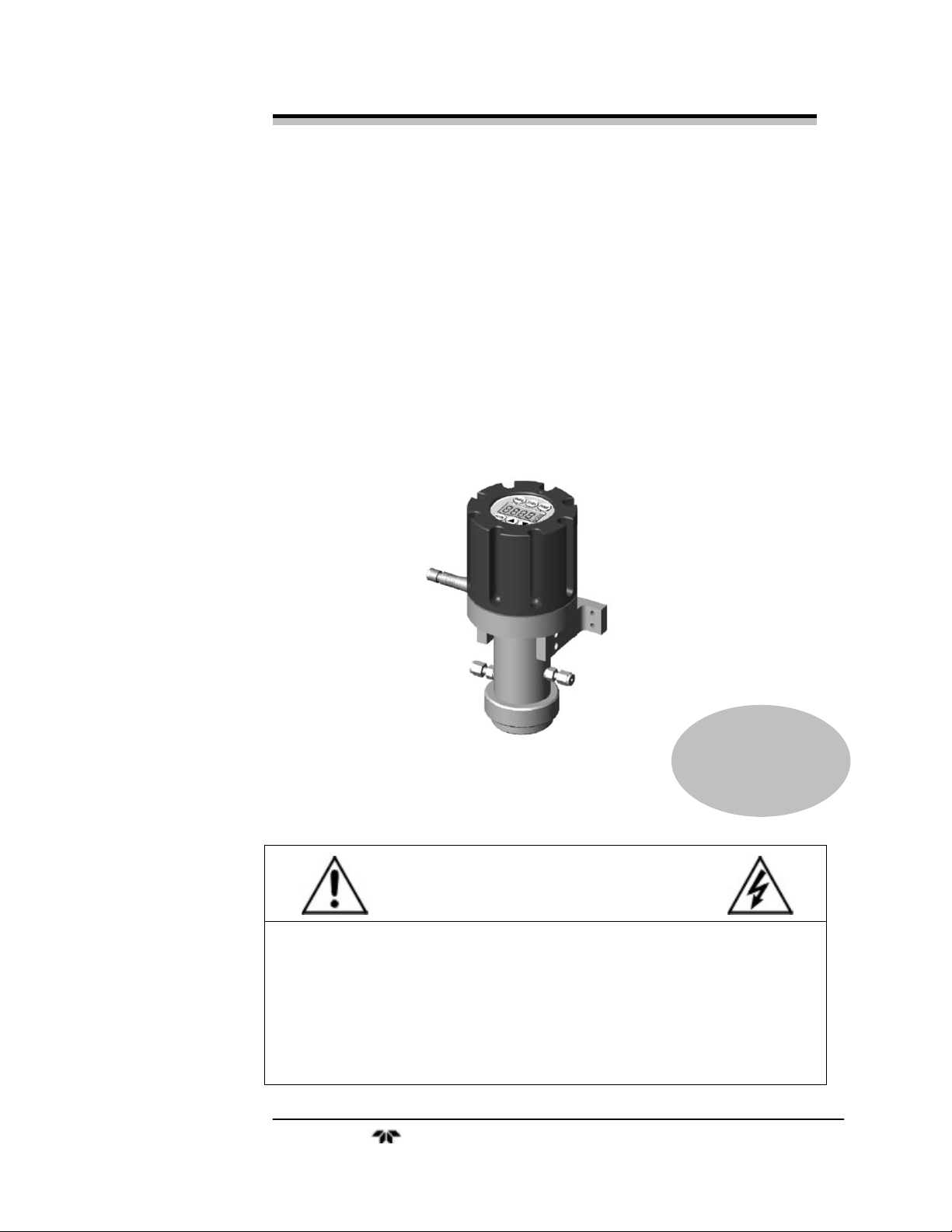
OPERATING INSTRUCTIONS FOR
INSTA-TRANS
Trace and Percent Oxygen
Transmitter
P/N M72103
08/02/10
DANGER
Toxic gases and or flammable liquids may be present in this monitoring system.
Personal protective equipment may be required when servicing this instrument.
Hazardous voltages exist on certain components internally which may persist
for a time even after the power is turned off and disconnected.
Only authorized personnel should conduct maintenance and/or servicing.
Before conducting any maintenance or servicing, consult with authorized
supervisor/manager.
Teledyne Analytical Instruments
Page 2

Insta-Trans
Copyright © 2010 Teledyne Analytical Instruments
All Rights Reserved. No part of this manual may be reproduced, transmitted, transcribed,
stored in a retrieval system, or translated into any other language or computer language in
whole or in part, in any form or by any means, whether it be electronic, mechanical,
magnetic, optical, manual, or otherwise, without the prior written consent of Teledyne
Analytical Instruments, 16830 Chestnut Street, City of Industry, CA 91749-1580.
Warranty
This equipment is sold subject to the mutual agreement that it is warranted by us free from
defects of material and of construction, and that our liability shall be limited to replacing or
repairing at our factory (without charge, except for transportation), or at customer plant at
our option, any material or construction in which defects become apparent within one year
from the date of shipment, except in cases where quotations or acknowledgements provide
for a shorter period. Components manufactured by others bear the warranty of their
manufacturer. This warranty does not cover defects caused by wear, accident, misuse,
neglect or repairs other than those performed by Teledyne or an authorized service center.
We assume no liability for direct or indirect damages of any kind and the purchaser by the
acceptance of the equipment will assume all liability for any damage which may result from
its use or misuse.
We reserve the right to employ any suitable material in the manufacture of our apparatus,
and to make any alterations in the dimensions, shape or weight of any parts, in so far as
such alterations do not adversely affect our warranty.
Important Notice
This instrument provides measurement readings to its user, an d serves as a to ol by whic h
valuable data can be gathered. The information provided by the instrument may assist the user
in eliminating potential hazards caused by his process; however, it is essential that all
personnel involved in the use of the instrument or its interface, with the process being
measured, be properly trained in the process itself, as well as all instrumentation related to it.
The safety of personnel is ultimately the responsibility of those who control process
conditions. While this instrument may be able to provide early warning of imminent
danger, it has no control over process conditions, and it can be misused. In particular, any
alarm or control systems installed must be tested and understood, both as to how they
operate and as to how they can be defeated. Any safeguards required such as locks, labels,
or redundancy, must be provided by the user or specifically requested of Teledyne at the
time the order is placed.
Therefore, the purchaser must be aware of the hazardous process conditions. The purchaser
is responsible for the training of personnel, for providing hazard warning methods and
instrumentation per the appropriate standards, and for ensuring that hazard warning devices
and instrumentation are maintained and operated properly.
Teledyne Analytical Instruments, the manufacturer of this instrument, cannot accept
responsibility for conditions beyond its knowledge and control. No statement expressed or
implied by this document or any information disseminated by the manufacturer or its
agents, is to be construed as a warranty of adequate safety control under the user’s process
conditions.
Teledyne Analytical Instruments ii
Page 3

Trace Oxygen Transmitter
Specific Model Information
The instrument for which this manual was supplied may
incorporate one or more options not supplied in the standard instrument.
Commonly available options are listed below, with check boxes. Any
that are incorporated in the instrument for which this manual is supplied
are indicated by a check mark in the box.
Instrument Serial Number: _______________________
Insta-Trans Transmitter Model: ____________
Cell Class:
A2C
A5
B1
B2C
L2C
B71875 Insta-Trace
B73016 Insta-Trace
Teledyne Analytical Instruments iii
Page 4

Insta-Trans
Table of Contents
Cell Class: ..................................................................................... iii
List of Figures .............................................................................. vi
Introduction ................................................................................... 1
1.1 Overview 1
1.2 Typical Applications 1
1.3 Main Features of the Transmitter 1
1.4 Operator Interface 2
Operational Theory ....................................................................... 5
2.1 Introduction 5
2.2 Micro-fuel Cell Sensor 5
2.2.1 Principles of Operation 5
2.2.2 Anatomy of a Micro-fuel Cell 6
2.2.3 Electrochemical Reactions 7
2.2.4 The Effect of Pressure 8
2.2.5 Calibration Characteristics 8
2.3 Sample System 10
2.4 Electronics and Signal Processing 11
Installation ................................................................................... 13
3.1 Unpacking the Transmitter 13
3.2 Mounting the Transmitter 13
3.3 Gas Connections 13
3.4 Electrical Connections 15
3.5 Installing the Micro-fuel Cell 16
3.6 Testing the System 17
Operation ..................................................................................... 19
4.1 Introduction 19
Teledyne Analytical Instruments iv
Page 5

Trace Oxygen Transmitter
4.2 The Range and Calibration Functions 19
4.3 Calibration 20
Maintenance ................................................................................. 23
5.1 Routine Maintenance 23
5.2 Cell Replacement 23
5.2.1 Storing and Handling Replacement Cells 23
5.2.2 When to Replace a Cell 24
5.2.3 Removing the Micro-fuel Cell 24
5.2.4 Cell Warranty 24
5.3 Insta-Trace Sensor 26
Appendix ...................................................................................... 29
Specifications 29
Recommended Spare Parts List 30
Drawings 32
Teledyne Analytical Instruments v
Page 6

Insta-Trans
List of Figures
Figure 1-1: Range Selection ............................................................ 3
Figure 2-1: Micro-fuel Cell ............................................................... 6
Figure 2-2: Cross Section of a Micro-fuel Cell ................................. 7
Figure 2-3: Characteristic Input/Output Curve for a Micro-fuel Cell ....... 9
Figure 2-4: Gas and Other Connections to the Transmitter .......... 10
Figure 2-5: Electronics Block Diagram .......................................... 12
Figure 3-1: Insta-Trans Connections and Mounting Dimensions ... 14
Figure 4-1: Insta-Trace Operation ................................................. 21
Figure 5-1: Cell Removal .............................................................. 26
Figure 5-2: Cell Removal Insta-Trace ........................................... 28
Teledyne Analytical Instruments vi
Page 7
Trace Oxygen Transmitter
DANGER
COMBUSTIBLE GAS USAGE
This is a general purpose instrument designed for usage in a
nonhazardous area. It is the customer's responsibility to
ensure safety especially when combustible gases are being
analyzed since the potential of gas leaks always exist.
WARNING
The customer should ensure that the principles of operating
of this equipment is well understood by the user. Misuse of
this product in any manner, tampering with its components,
or unauthorized substitution of any component may
adversely affect the safety of this instrument.
Since the use of this instrument is beyond the control of
Teledyne, no responsibility by Teledyne, its affiliates, and
agents for damage or injury from misuse or neglect of this
equipment is implied or assumed.
Teledyne Analytical Instruments vii
Page 8

Insta-Trans
Teledyne Analytical Instruments viii
Page 9

Trace Oxygen Transmitter Introduction
Introduction
1.1 Overview
The Teledyne Analytical Instruments Insta-Trans Trace Oxygen
Transmitter is a versatile instrument for detecting oxygen at the parts-per million (ppm) level in a variety of gases. This manual covers the Insta-Tr ans
Trace Oxygen Transmitter. These units are NEMA-4 rated and may be used
in hazardous environments. The Insta-Trans is also Factory Mutual approved
when installed in accordance with drawing D-73226 located in the back of
this manual.
1.2 Typical Applications
A few typical applications of the Insta-Trans are:
Monitoring inert gas blanketing
Air separation and liquefaction
Chemical reaction monitoring
Semiconductor manufacturing
Petrochemical process control
Quality assurance
Gas analysis certification.
1.3 Main Features of the Transmitter
The Insta-Trans Trace Oxygen Transmitter is sophisticated yet
simple to use. The main features of the analyzer include:
3½ digit LCD display with range and calibration
annunciators.
Six ranges: 0-10 ppm through 0-25%.
Stainless steel cell block.
Teledyne Analytical Instruments 1
Page 10

Introduction Insta-Trans
Simple push-button calibration and range selection.
Advanced Micro-fuel Cell, redesigned for trace analysis, has
a one year warranty and an expected lifetime of two years.
Air-calibration range for convenient spanning at 20.9 %.
True 2-wire 4-20 mA powered loop interface.
1.4 Operator Interface
The standard Insta-Trans is housed in a rugged NEMA-4 rated
metal case with all switches and the display accessible from the outside.
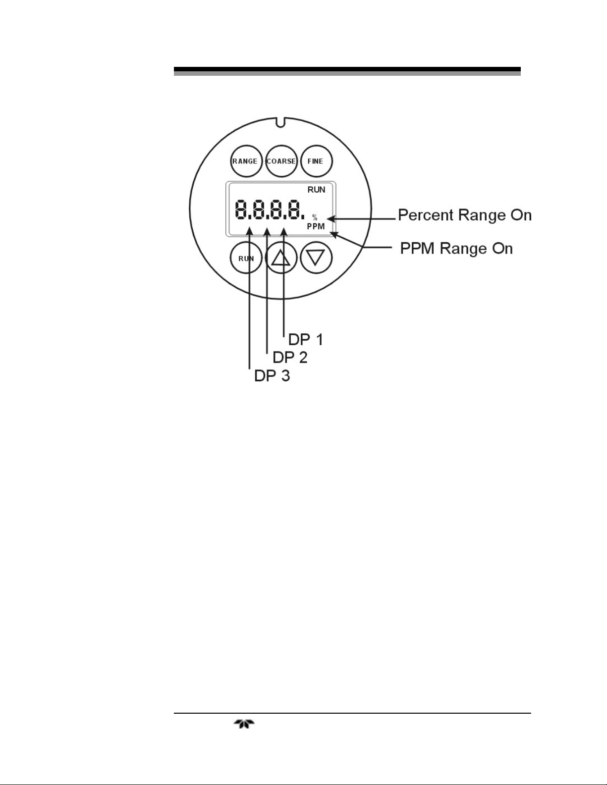
Figure 1-1 illustrates the Insta-Trans display and switches while Table 11 shows the decimal point (DP) location for the various ranges.
Function Keys: Six touch-sensitive membrane switches are used to set
the range and calibrate the transmitter.
RANGE Selects the Range mode and sets the desired range.
COARSE Selects the Coarse calibration mode.
FINE Selects the Fine calibration mode.
RUN Selects the Run mode.
▲ Used to adjust the calibration upward in Coarse
and Fine mode.
▼ Used to adjust the calibration downward in
Coarse and Fine mode.
DISPLAY 3 1/2 digit O
concentration LCD display with
2
annunciators
Table 1-1: Decimal Location for Selected Range
Range Decimal Location
0-10 PPM Decimal Point (DP) 2
0-100 PPM Decimal Point (DP) 1
0-1000 PPM No Decimal Point
0-1% Decimal Point (DP) 3
0-10% Decimal Point (DP) 2
0-25% Decimal Point (DP) 2
Teledyne Analytical Instruments 2
Page 11
Trace Oxygen Transmitter Introduction
Figure 1-1: Range Selection
Teledyne Analytical Instruments 3
Page 12

Introduction Insta-Trans
Teledyne Analytical Instruments 4
Page 13

Trace Oxygen Transmitter Operational Theory
Operational Theory
2.1 Introduction
The transmitter is composed of three subsystems:
1. Micro-fuel Cell Sensor
2. Sample System
3. Electronic Signal Processing, Display and Control
The sample system is designed to accept the sample gas and
transport it through the transmitter without contaminating or altering the
sample prior to analysis. The Micro-fuel Cell is an electrochemical
galvanic device that translates the amount of oxygen present in the
sample into an electrical current. The electronic signal processing,
display and control circuits simplify operation of the transmitter and
accurately displays the sampled data.
2.2 Micro-fuel Cell Sensor
2.2.1 Principles of Operation
The oxygen sensor used in the Insta-Trans series is a Micro-fuel
Cell designed and manufactured by Analytical Instruments. It is a sealed
plastic disposable electrochemical transducer.
The active components of the Micro-fuel Cell are a cathode, an
anode, and the 15% aqueous KOH electrolyte in which they are
immersed. The cell converts the energy from a chemical reaction into an
electrical current in an external electrical circuit. Its action is similar to
that of a battery.
There is, however, an important difference in the operation of a
battery as compared to the Micro-fuel Cell: In the battery, all reactants
are stored within the cell, whereas in the Micro-fuel Cell, one of the
reactants (oxygen) comes from outside the device as a constituent of the
sample gas being analyzed. The Micro-fuel Cell is therefore a hybrid
Teledyne Analytical Instruments 5
Page 14

Operational Theory Insta-Trans
between a battery and a true fuel cell. (All of the reactants are stored
externally in a true fuel cell.)
2.2.2 Anatomy of a Micro-fuel Cell
The Micro-fuel Cell is a cylinder only 1¼ inches in diameter and
1¼ inches thick. It is made of an extremely inert plastic, which can be
placed confidently in practically any environment or sample stream. It is
effectively sealed, although one end is permeable to oxygen in the
sample gas. The other end of the cell is a contact plate consisting of two
concentric foil rings. The rings mate with spring-loaded contacts in the
sensor block assembly and provide the electrical connection to the rest
of the analyzer. Figure 2-1 illustrates the external features.
Figure 2-1: Micro-fuel Cell
Refer to Figure 2-2, Cross Section of a Micro-fuel Cell, which
illustrates the following internal description.
At the top end of the cell is a diffusion membrane of Teflon,
whose thickness is very accurately controlled. Beneath the diffusion
membrane lies the oxygen sensing element—the cathode—with a
surface area almost 4 cm
2
. The cathode has many perforations to ensure
sufficient wetting of the upper surface with electrolyte, and it is plated
with an inert metal.
The anode structure is below the cathode. It is made of lead and has
a proprietary design which is meant to maximize the amount of metal
available for chemical reaction.
Teledyne Analytical Instruments 6
Page 15

Trace Oxygen Transmitter Operational Theory
Figure 2-2: Cross Section of a Micro-fuel Cell (not to scale)
At the rear of the cell, just below the anode structure, is a flexible
membrane designed to accommodate the internal volume changes that
occur throughout the life of the cell. This flexibility assures that the
sensing membrane remains in its proper position, keeping the electrical
output constant.
The entire space between the diffusion membrane, above the
cathode, and the flexible rear membrane, beneath the anode, is filled
with electrolyte. Cathode and anode are submerged in this common
pool. They each have a conductor connecting them to one of the external
contact rings on the contact plate, which is on the bottom of the cell.
2.2.3 Electrochemical Reactions
The sample gas diffuses through the Teflon membrane. Any
oxygen in the sample gas is reduced on the surface of the cathode by the
following HALF REACTION:
O
+ 2H2O + 4e– → 4OH– (cathode)
2
(Four electrons combine with one oxygen molecule—in the
presence of water from the electrolyte—to produce four hydroxyl ions.)
When the oxygen is reduced at the cathode, lead is simultaneously
oxidized at the anode by the following HALF REACTION:
Teledyne Analytical Instruments 7
Page 16

Operational Theory Insta-Trans
Pb + 2OH– → Pb+2 + H2O + 2e– (anode)
(Two electrons are transferred for each atom of lead that is
oxidized. Therefore it takes two of the above anode reactions to balance
one cathode reaction and transfer four electrons.)
The electrons released at the surface of the anode flow to the
cathode surface when an external electrical path is provided. The current
is proportional to the amount of oxygen reaching the cathode. It is
measured and used to determine the oxygen concentration in the gas
mixture.
The overall reaction for the fuel cell is the SUM of the half
reactions above, or:
2Pb + O2 → 2PbO
(These reactions will hold as long as no gaseous components
capable of oxidizing lead—such as iodine, bromine, chlorine and
fluorine—are present in the sample.)
The output of the fuel cell is limited by (1) the amount of oxygen in
the cell at the time and (2) the amount of stored anode material.
In the absence of oxygen, no current is generated.
2.2.4 The Effect of Pressure
In order to state the amount of oxygen present in the sample in
parts-per-million or a percentage of the gas mixture, it is necessary that
the sample diffuse into the cell under constant pressure.
If the total pressure increases, the rate that oxygen reaches the
cathode through the diffusing membrane will also increase. The electron
transfer, and therefore the external current, will increase, even though
the oxygen concentration of the sample has not changed. It is therefore
important that the sample pressure at the fuel cell (usually vent pressure)
remain relatively constant between calibrations.
2.2.5 Calibration Characteristics
Given that the total pressure of the sample gas on the surface of the
Micro-fuel Cell input is constant, a convenient characteristic of the cell
is that the current produced in an external circuit is directly proportional
to the rate at which oxygen molecules reach the cathode, and this rate is
directly proportional to the concentration of oxygen in the gaseous
Teledyne Analytical Instruments 8
Page 17

Trace Oxygen Transmitter Operational Theory
mixture. In other words it has a linear characteristic curve, as shown in
Figure 2-3. Measuring circuits do not have to compensate for
nonlinearities.
In addition, since there is zero output in the absence oxygen, the
characteristic curve has close to an absolute zero (within ± 0.5 ppm
oxygen).
Figure 2-3: Characteristic Input/Output Curve for a Micro-fuel Cell
Teledyne Analytical Instruments 9
Page 18

Operational Theory Insta-Trans
2.3 Sample System
The sample system delivers gases to the Micro-fuel Cell sensor
from the transmitter gas inlet. Depending on the mode of operation
either sample or calibration gas is delivered.
The Insta-Trans sample system is designed and fabricated to ensure
that the oxygen concentration of the gas is not altered as it travels
through the sample system. The sample encounters almost no dead
space. This minimizes residual gas pockets that can interfere with trace
analysis.
The sample system for the standard instrument incorporates 1/8
inch tube fittings for sample inlet and outlet connections. For metric
system installations, 6 mm adapters can be supplied with each
instrument to be used if needed (consult factory). The sample gas flows
through the transmitter as shown in Figure 2-4.
Figure 2-4: Gas and Other Connections to the Transmitter
Teledyne Analytical Instruments 10
Page 19

Trace Oxygen Transmitter Operational Theory
2.4 Electronics and Signal Processing
The Insta-Trans Trace Oxygen transmitter uses standard electronic
circuitry. Power is supplied via the 4-20 mA current loop.
The processing electronics are located inside the transmitter case.
Three boards are accessible after removing the top housing. Figure 2-5 is
a block diagram of the transmitter electronics.
In the presence of oxygen the cell generates a current. A current to
voltage amplifier converts this current to a voltage, which is amplified in
the second stage amplifier.
The second stage amplifier also supplies temperature compensation
for the oxygen sensor output. This amplifier circuit incorporates a
thermistor, which is physically located in the cell block. The thermistor
is a temperature dependent resistance that changes the gain of the
amplifier in proportion to the temperature changes in the block. This
change is inversely proportional to the change in the cell output due to
the same temperature changes. The result is a signal that is temperature
independent. The output from the second stage amplifier is sent to the
3 1/2 digit DVM/Display and voltage to current converter/driver.
The 3 1/2 digit DVM/Display provides a visual indication of the
oxygen concentration in ppm or % depending on the range selected.
Range selection and calibration information are entered from the key
pad and processed through the key pad control, the input range selection
and the calibration control circuits. All power needed to run the InstaTrans transmitter is derived from the signal current loop. Calibration
settings are maintained indefinitely when the signal current loop is
disconnected. Range settings are maintained for a minimum of 72 hours
through the use of a 0.1 Farad storage capacitor when the signal current
loop is disconnected. The transmitter always defaults to Run mode when
the signal current loop is connected.
Teledyne Analytical Instruments 11
Page 20

Operational Theory Insta-Trans
Figure 2-5: Electronics Block Diagram
Teledyne Analytical Instruments 12
Page 21

Trace Oxygen Transmitter Installation
Installation
Installation of the Insta-Trans Transmitter includes:
Unpacking
Mounting
Gas connections
Electrical connections
Installing the Micro-fuel Cell
Testing the system.
3.1 Unpacking the Transmitter
The transmitter is shipped with all the materials you need to install
and prepare the system for operation. Carefully unpack the transmitter
and inspect it for damage. Immediately report any damage to the
shipping agent.
3.2 Mounting the Transmitter
The Insta-Trans is intended for indoor or outdoor use.
The Insta-Trans transmitter is provided with a wall mount bracket.
Refer to Figure 3-1 for mounting information and dimensions. The
display and operator control switches are located on the top of the
transmitter. This should be taken into consideration when determining
mounting location. Mount the transmitter with the sensor housing
vertical and the cell holder on the bottom.
3.3 Gas Connections
The unit is manufactured with 1/8 inch tube fittings (consult
factory for other sizes). For a safe connection:
Teledyne Analytical Instruments 13
Page 22

Installation Insta-Trans
1. Insert the tube into the tube fitting, and finger-tighten the nut
until the tubing in the fitting cannot be rotated freely by hand.
(This may require an additional 1/8 turn beyond finger-tight.)
2. Hold the fitting body steady with a backup wrench, and with
another wrench rotate the nut another 1-1/4 turns.
Figure 3-1: Insta-Trans Connections and Mounting Dimensions
SAMPLE IN: Gas connections are made at the SAMPLE IN and
EXHAUST OUT connections.
The gas pressure in should be reasonably regulated. A flow control
device must be installed before the sample in port if the sample pressure
is above 0.5 psig.
Teledyne Analytical Instruments 14
Page 23

Trace Oxygen Transmitter Installation
If greater flow is required for improved response time (over 20
SCFH), install a bypass in the sampling system upstream of the analyzer
input.
EXHAUST OUT: Exhaust connections must be consistent with the
hazard level of the constituent gases. Check local, state, and federal
laws, and ensure that the exhaust stream vents to an appropriately
controlled area if required. The exhaust should be vented to atmospheric
pressure, through a short length of tubing (3'). The vent tubing should
not be less than 1/8".
3.4 Electrical Connections
The Insta-Trans analyzer requires two electrical connections. A
chassis ground connection should be made to the left side of the
mounting bracket. This is required to reduce the sensitivity to radio
frequency interference (RFI). An adequate ground connection is can be
established by mounting the analyzer to a metal structure, or attaching a
ground cable with lug (3/8") to the left side mounting bolt.
The signal and power are supplied by a single 4 pin electrical
connector on the left side of the analyzer. The Insta-Trans is supplied
with a twenty-four inch cable which mates with the power/signal
connector. Other cable lengths are available or the mating connector can
be supplied for customer use, see spare parts list in the rear of the
manual.
Wiring: The Insta-Trans is equipped with a four pin removable
connector (screw connections). The connector allows the user to easily
install or remove the analyzer. The connector should be wired per
B71625, interconnection is per A71629 (D73226 for FM approved
installation).
For Factory Mutual approved installations, the interconnection
cable must not exceed the following values:
GP AB 0.09 f and 3 mH inductance
GP C 0.3 f and 1 mH inductance
GP D 0.9 f and 3 mH inductance
The cable or wire required will depend on the specific application. A
shielded cable should be used when ever possible to improve resistance to
radio interference. The wire gage should be selected based on the length
Teledyne Analytical Instruments 15
Page 24

Installation Insta-Trans
of the cable. A minimum wire gage of 22 is recommended. The maximum
wire gage is limited by the size of the connector. A larger gage wire is
required for longer cable runs due to the voltage drop associated with the
cable resistance. A 1000 foot 22 gage cable will have a voltage drop of
0.59 VDC (29.5 ohms x 20ma) at full scale. A 1000 foot 18 gage cable
will have a voltage drop of 0.26 VDC (12.96 ohms x 20ma). The above
voltage will be added to the minimum voltage required for the transmitter.
A typical installation will include a load resistor. The value of the
resistor is dependent on the full-scale output voltage signal required. For a
full-scale output of 5 VDC the resistor value is 250 ohms (5V/20mA.).
For a full-scale output of 1 VDC the resistor value will be 50 ohms
(1V/20mA). The output voltage is also added to the minimum voltage for
the transmitter.
The operating voltage range of the transmitter is 9.3 – 30 VDC. The
wiring and load resistor voltage drops must be included in determining the
minimum voltage requirement. The minimum operating voltage required
with a 500 foot 20 gage cable and a 250 ohm load resistor is 14.4 VDC
(9.3V + (5.1 + 250) ohms x 20ma).
For Intrinsically Safe (IS) installation, special considerations are
required. The Insta-Trans analyzer has been designed to be Intrinsically
Safe when used with a properly selected and installed safety barrier. This
design utilizes redundant safety features to prevent the Insta-Trans from
becoming an ignition source in the event of a circuit failure. The user
should consult with the proper certifying agency prior to installation. Safety
barriers reduce the possibility of fires or explosion in hazardous locations
by limiting the energy available for ignition. Reference the FM
interconnection diagram D-73226.
3.5 Installing the Micro-fuel Cell
The Micro-fuel Cell is not installed in the cell block when the
instrument is shipped. It must be install before the analyzer is placed in
service.
Once it is expended, or if the cell (trace O
long, the Micro-fuel Cell will need to be replaced (B1 cells are designed
for use in % levels of O
such as air). The cell could also require
2
replacement if the instrument has been idle for too long.
) is exposed to air for too
2
Teledyne Analytical Instruments 16
Page 25

Trace Oxygen Transmitter Installation
When the Micro-fuel Cell needs to be installed or replaced, follow
the procedures in Chapter 5, Maintenance, for removing and installing
cells.
3.6 Testing the System
Before connecting the signal wires to the transmitter:
Check the integrity and accuracy of the gas connections.
Make sure there are no leaks.
Verify that the restriction device has been properly installed
(see section 3.3).
Check that inlet sample pressure is within the accepted range
(see section 3.3).
Connect the signal wires and energize the signal line, and test the
transmitter by performing the following:
1. Observe that the LCD display illuminates and that the
transmitter starts up in Run mode. If the transmitter is being
energizer for the first time or has been disconnected from the
power for a long period of time, wait about 60 seconds for
the 0.1 Farad storage capacitor to charge up before
attempting any tests.
2. If the right three digits of the LCD display are blank, the
transmitter is in an over range condition. Push the RANGE
button once to enter the Range Select mode. Observe that the
RNG annunciator illuminates. Push the RANGE button until
the transmitter displays an “in range” condition.
Note: Tthe transmitter can display a 99.9% over range condition,
so select a range where the left-most digit is blank.
3. Push the COARSE button. Observe that the CRS
annunciator illuminates on the display.
4. Push the ▲ and▼buttons. Observe that the gas
concentration reading goes up and down in rather coarse
increments as the buttons are pushed.
5. Push the FINE button.Observe that the CRS annunciator
goes out and the FIN annunciator illuminates on the display.
Teledyne Analytical Instruments 17
Page 26

Installation Insta-Trans
6. Push the ▲ and▼buttons. Observe that the gas
concentration reading goes up and down in fine increments
as the buttons are pushed.
7. Push the RUN button. Observe that the FIN and RNG
annunciators go out. The transmitter is now in Run mode.
Teledyne Analytical Instruments 18
Page 27

Trace Oxygen Transmitter Operation
Operation
4.1 Introduction
Once the transmitter has been installed, it must be configured to
your application. To do this you must:
Set the range.
Calibrate the instrument.
4.2 The Range and Calibration Functions
The transmitter is calibrated by using span gas.
Although the instrument can be spanned using air, a span gas with a
known oxygen concentration in the range of 70–90% of full scale of the
range of interest is recommended. Since the oxygen concentration in air
is 20.9% (209,000 ppm), the cell can take a long time to recover if the
instrument is used for trace oxygen analysis immediately following
calibration in air.
Connect the calibration gases to the transmitter according to the
instructions given in Section 3.3, Gas Connections, observing all the
prescribed precautions.
The gas supply should be off or set to a low flow before
connecting it to the transmitter, and be sure not to obstruct the
sample vent.
CAUTION: IN THE EVENT OF LOSS OF FLOW THROUGH THE
TRANSMITTER, IF THE VENT IS VENTED TO A
LOCATION OF HIGH OXYGEN CONTENT, OXYGEN
WILL BACK DIFFUSE THROUGH THE VENT LINE
AND IN MOST CASES QUICKLY SATURATE THE
CELL WITH OXYGEN WHICH CAN THEN REQUIRE A
LONG PURGE DOWN TIME FOR THE SENSOR
WHEN USED FOR LOW OXYGEN CONCENTRATION
MEASUREMENTS. IN THE EVENT THAT FLOW IS
INTERRUPTED INTO THE TRANSMITTER, IT IS
Teledyne Analytical Instruments 19
Page 28

Operation Insta-Trans
SUGGESTED THAT THE USER DO ONE OF THE
FOLLOWING:
1. Bag the sensor in nitrogen during this time
2. Install a shut off valve on the vent port of the
transmitter or somewhere within the users
sample system.
4.3 Calibration
Follow the following instructions to calibrate the Insta-Trans Trace
Oxygen Transmitter. Refer to figure 4-1.
1. Select range to be calibrated and enable calibration gas flow.
2. Wait until the display reading is stable before beginning the
span adjustment.
3. Once the reading is stable press COARSE to select the
Coarse mode.
4. Adjust the ‘COARSE’ range up or down using the ▲ and ▼
keys until the display reads the value that is closest to the
calibration gas oxygen concentration level.
5. When set to a value close to the calibration gas concentration
level press FINE to select the Fine mode.
6. Adjust the ‘FINE’ range up or down until the display reads
the value of the calibration gas oxygen concentration level. If
unable to reduce the Fine range lower, proceed to step 7. If
unable to increase the Fine range higher, proceed to step 8.
Else, proceed to step 9.
7. Set the transmitter into ‘COARSE’ mode and adjust the
Coarse range DOWN exactly 4 increments. Then, go back to
step 5.
8. Set the transmitter into ‘COARSE’ mode and adjust the
Coarse range UP exactly 4 increments. Then, go back to step
5.
9. Press RUN to complete calibration.
Teledyne Analytical Instruments 20
Page 29

Trace Oxygen Transmitter Operation
Figure 4-1: Insta-Trace Operation
Teledyne Analytical Instruments 21
Page 30

Operation Insta-Trans
Teledyne Analytical Instruments 22
Page 31

Trace Oxygen Transmitter Maintenance
Maintenance
5.1 Routine Maintenance
Aside from normal cleaning and checking for leaks at the gas
connections, routine maintenance is limited to replacing Micro-fuel
Cells and recalibration. For recalibration, see Section 4 Calibration.
WARNING: SEE WARNINGS ON THE TITLE PAGE OF THIS
MANUAL.
5.2 Cell Replacement
A Micro-fuel Cell is a sealed electrochemical transducer with no
electrolyte to change or electrodes to clean. When the cell reaches the
end of its useful life, it is replaced. The spent fuel cell should be
discarded according to local regulations. This section describes fuel cell
care as well as when and how to replace it.
5.2.1 Storing and Handling Replacement Cells
To have a replacement cell available when it is needed, TAI
recommends that one spare cell be purchased 9-10 months after
commissioning the Insta-Trans, or shortly before the end of the cell's
one year warranty period.
CAUTION: DO NOT STOCKPILE CELLS. THE WARRANTY PERIOD
STARTS ON THE DAY OF SHIPMENT.
The spare cell should be carefully stored in an area that is
not subject to large variations in ambient temperature
(75 °F nominal) or to rough handling.
WARNING: THE SENSOR USED IN THE INSTA-TRANS TRACE
OXYGEN TRANSMITTER USES ELECTROLYTES
WHICH CONTAIN TOXIC SUBSTANCES, MAINLY
Teledyne Analytical Instruments 23
Page 32

Maintenance Insta-Trans
LEAD AND POTASSIUM HYDROXIDE, THAT CAN BE
HARMFUL IF TOUCHED, SWALLOWED, OR
INHALED. AVOID CONTACT WITH ANY FLUID OR
POWDER IN OR AROUND THE UNIT. WHAT MAY
APPEAR TO BE PLAIN WATER COULD CONTAIN
ONE OF THESE TOXIC SUBSTANCES. IN CASE OF
EYE CONTACT, IMMEDIATELY FLUSH EYES WITH
WATER FOR AT LEAST 15 MINUTES. CALL
PHYSICIAN. (SEE APPENDIX, MATERIAL SAFETY
DATA SHEET.)
CAUTION: DO NOT DISTURB THE INTEGRITY OF THE CELL
PACKAGE UNTIL THE CELL IS TO ACTUALLY BE
USED. IF THE CELL PACKAGE IS PUNCTURED AND
AIR IS PERMITTED TO ENTER, THE CELL WILL
REQUIRE AN EXCESSIVELY LONG TIME TO REACH
ZERO AFTER INSTALLATION (1-2 WEEKS!).
5.2.2 When to Replace a Cell
The characteristics of the Micro-fuel Cell show an almost constant
output throughout its useful life and then falls off sharply towards zero
at the end. Cell failure in the Insta-Trans is usually characterized by the
inability to span or excessive offset when used on low ppm ranges.
Before replacing the cell:
1. Check your span gas to make sure it is within specifications.
2. Check for leaks downstream from the cell, where oxygen
may be leaking into the system.
If there are no leaks and the span gas is OK, replace the cell.
5.2.3 Removing the Micro-fuel Cell
Remove the Cell Holder by holding the bottom in place and
unscrewing the Collar until the Cell Holder falls out with the Cell.
Remove the new cell from its package, and carefully remove the
shorting clip. Place the cell on the cell holder with the screen side facing
down and tighten the cell holder onto the instrument. See Figure 5-1.
5.2.4 Cell Warranty
The Insta-Trace cell is the standard trace sensor for the Insta-Trans.
It is suitable for use in applications where the O
level is being measured
2
on a ppm range. The warranty period of the Insta-Trace is six months
Teledyne Analytical Instruments 24
Page 33

Trace Oxygen Transmitter Maintenance
from the date of shipment. This sensor has a life expectancy of eight
months when used in trace measurement applications.
The B1 cell is the standard percent sensor for use with Insta-Trans. It
is suitable for use when the analyzer will be used on a percent range. The
B1 has a warranty period of six months from the date of shipment and a
life expectancy of eight months in air.
The A2C cell is recommended for use in trace applications were
CO
is a major component of the sample gas. The warranty period of the
2
A2C is six months from the date of shipment. This sensor has a life
expectancy of eight months when used in trace measurement
applications.
The optional Class L2C Micro-fuel Cell can be used in the Insta-Trans.
This cell is a long life cell for use in trace (ppm) applications and is warranted
for 1 year from the date of shipment. Note any Addenda attached to the front
of this manual for special information applying to your instrument.
With regard to spare cells, warranty period begins on the date of
shipment. The customer should purchase only one spare cell (per section
5.2.1). Do not attempt to stockpile spare cells.
The B1, B2C, Insta-Trace, and L2C cells are not designed for
applications where CO2 is a major component in the sample,
however intermittent concentrations of 1,000 ppm or less will not
adversely effect the cell performance. Consult TAI for available options
for either intermittent or continuous CO2 exposure.
The A2C cell is recommended for trace applications when the
sample gas contains significant levels of CO
. The A2C cell is suitable
2
for CO2 concentration of 0 to 100%.
If a cell was working satisfactorily, but ceases to function before
the warranty period expires, the customer will receive credit toward the
purchase of a new cell.
If you have a warranty claim, you must return the cell in question to
the factory for evaluation. If it is determined that failure is due to faulty
workmanship or material, the cell will be replaced at no cost to you.
Teledyne Analytical Instruments 25
Page 34

Maintenance Insta-Trans
Figure 5-1: Cell Removal
5.3 Insta-Trace Sensor
Teledyne’s Insta-Trace Sensor (patent pending) provides rapid
sensor installation recovery time. The Insta-Trace system allows a new
sensor to be installed and working at low ppm (parts per million) in a
matter of minutes. The insta-Trace option includes the Insta-Trace
Sensor and a special Insta-Trace cell holder (the B2 cell adapter is not
used).
Teledyne Analytical Instruments 26
Page 35

Trace Oxygen Transmitter Maintenance
Any Insta-Trans can be converted to an Insta-Trace by substituting
the sensor and cell holder (see Spare Parts Listing in the Appendix).
The Insta-Trace system works by shielding the sensitive membrane
from air during the installation process. These special cells have an outer
membrane which seals the sensing membrane in a bath of N
until the
2
membrane is punctured during the installation. External gas can reach
the sensing membrane only after the external membrane is pierced. This
process prevents air from contaminating the sensor during installation
thus allowing rapid recovery to low ppm levels. For best results, the
proper installation must be followed.
To install the Insta-Trace:
The Insta-Trans transmitter must be purged with sample gas at a
flow rate of approximately 0.2 SCFH during installation.
Remove the Insta-Trace cell holder by unscrewing the collar (see
Figure 5-2).
Remove the Insta-Trace sensor from the double bags.
Remove the shorting plug from the rear of the sensor.
Install the sensor in the transmitter with the contact surface (two
concentric gold circles) facing up, and the membrane facing
down toward the cell holder.
Orient the cell holder to align the registration pin with the hole in
the cell holder.
Push the cell holder firmly in place while rotating the collar (see
Figure 5-2). The collar should be tightened finger-tight only.
Teledyne Analytical Instruments 27
Page 36

Maintenance Insta-Trans
Figure 5-2: Cell Removal Insta-Trace
Teledyne Analytical Instruments 28
Page 37

Trace Oxygen Transmitter Appendix
Appendix
Specifications
System Enclosure: Weather resistant, bulkhead mounted
Power Requirements: 15V nominal, reverse polarity protected.
9.3VDC-30VDC. V
safety barrier and/or load resistor used.
For Factory Mutual Approved Intrinsically
Safe Operation, an approved safety barrier
must be used. Ref. D-73226
dependent upon
min
Ranges: 0–10ppm through 0–25% Oxygen
Accuracy: ± 2% of full scale at constant temperature
and pressure (at the temperature and
pressure of calibration), except ± 1ppm on
0–10ppm range.
± 5% of full scale over operating
temperature range (once thermal
equilibrium has been reached), except ±
1ppm on 0–10ppm range.
Response Time (90%): Sensor Response Time + Electronic
Response Time = 40 seconds @ 77°F
(25°C)—(with standard cell)
Operating Temperature: 32–122°F (0–50°C)
Relative Humidity: 0-100% RH, NEMA-4 rated.
Stability: ± 1% in 24 hours (at constant temperature)
Reproducibility: ± 1% of full scale at constant temperature
Sensor Type: Micro-fuel Cell class B2C, L2C, B1, A2C,
Insta-Trace
Signal Output: 4–20 mA DC
Teledyne Analytical Instruments 29
Page 38

Appendix Insta-Trans
Recommended Spare Parts List
Qty. Part Number Description
1 B617 IS Safety Barrier MTL 7087+
1 B616 IS Safety Barrier MTL 787S+
1 B604 IS Safety Barrier(Galvanic MTL 5041
1 B70986 Standard Cell Holder
1 B71625A Power/Signal Cable 2 Ft.
1 B71625D Power/Signal Cable 25 ft (optional)
1 B66378 Cell Adapter (B1, B2, AC) Insta-Trace Option
1 D71159A PCB Display
1 D71159B PCB Logic Board
1 D71159C PCB I/O
1* C6689-A2C A2C Micro-fuel Cell
1* C6689-A5 A5 Micro-fuel Cell
1* C6689-B1 B1 Micro-fuel Cell
1* C6689-B2C B2C Micro-fuel Cell
1* B73016 Insta-Trans Sensor A-type
1* B71875 Insta-Trans Sensor B-type
1 CP2070 Connector, Power Signal
2 O290 O-Rings
1 B72087 Insta-Trace Cell Holder
* Application Dependant. Only 1 required
A minimum charge is applicable to spare parts orders.
Note: Orders for replacement parts should include the part
number (if available) and the model and serial number of
the instrument for which the parts are intended.
Teledyne Analytical Instruments 30
Page 39

Trace Oxygen Transmitter Appendix
Orders should be sent to:
TELEDYNE Analytical Instruments
16830 Chestnut Street
City of Industry, CA 91749-1580
Phone (626) 934-1500, Fax (626) 961-2538
Web: www.teledyne-ai.com
or your local representative.
Teledyne Analytical Instruments 31
Page 40

Appendix Insta-Trans
Drawings
Teledyne Analytical Instruments 32
 Loading...