


i
CombiFlash® R
f
Installation Guide
For indoor use only
COPYRIGHT © 2002, 2004 by
Teledyne Isco, Inc.
4700 Superior St., Lincoln, Nebraska, U.S.A. 68504
Phone: (402) 464-0231
Toll Free: (800) 228-4373
FAX: (402) 465-3022
Revision A: August 15, 2007
Part #60-5233-385

iii
CombiFlash® R
f
Installation Guide
Table of Contents
1. Introduction
1.1 Documentation Overview . . . . . . . . . . . . . . . . . . . . . .1-1
1.2 Product Overview . . . . . . . . . . . . . . . . . . . . . . . . . . . .1-1
1.3 Operating Overview . . . . . . . . . . . . . . . . . . . . . . . . . .1-3
1.3.1 Multiple Control Possibilities . . . . . . . . . . . . .1-3
1.3.2 File Storage . . . . . . . . . . . . . . . . . . . . . . . . . . . .1-3
1.4 Specifications . . . . . . . . . . . . . . . . . . . . . . . . . . . . . . .1-4
1.5 Controls, Indicators, and Features . . . . . . . . . . . . . . 1-5
1.6 Safety . . . . . . . . . . . . . . . . . . . . . . . . . . . . . . . . . . . . .1-8
1.6.1 Hazard Severity Levels . . . . . . . . . . . . . . . . . .1-9
1.6.2 Hazard Symbols . . . . . . . . . . . . . . . . . . . . . . . 1-10
1.7 For Additional Information . . . . . . . . . . . . . . . . . . .1-11
2. System Preparation
2.1 Unpacking the Unit . . . . . . . . . . . . . . . . . . . . . . . . . .2-1
2.2 Instrument Location . . . . . . . . . . . . . . . . . . . . . . . . .2-1
2.3 Connect Power . . . . . . . . . . . . . . . . . . . . . . . . . . . . . .2-2
2.4 Connect Solvent Lines . . . . . . . . . . . . . . . . . . . . . . . .2-2
2.5 Connect Waste Lines . . . . . . . . . . . . . . . . . . . . . . . . . 2-5
2.6 Optional External Gas . . . . . . . . . . . . . . . . . . . . . . . . 2-9
2.7 Connect and Route Drain Lines . . . . . . . . . . . . . . . .2-9
2.8 Position the System . . . . . . . . . . . . . . . . . . . . . . . . . .2-9
2.9 Install Collection Tube Racks . . . . . . . . . . . . . . . . .2-10
2.10 Turn on Power . . . . . . . . . . . . . . . . . . . . . . . . . . . . .2-12
2.11 Configure the System . . . . . . . . . . . . . . . . . . . . . . . . 2-12
2.11.1 Solvents . . . . . . . . . . . . . . . . . . . . . . . . . . . . . . 2-12
2.11.2 General Settings . . . . . . . . . . . . . . . . . . . . . . . 2-13
2.11.3 Vapor Limit . . . . . . . . . . . . . . . . . . . . . . . . . . .2-13
2.11.4 Automatically Print Report at End of Run . . 2-14
2.11.5 Enable Run Length Extension . . . . . . . . . . . .2-14
2.11.6 Set Default Tube Volumes . . . . . . . . . . . . . . . 2-15
2.11.7 Set Date/Time . . . . . . . . . . . . . . . . . . . . . . . . .2-15
2.11.8 Default Run Units . . . . . . . . . . . . . . . . . . . . .2-16
2.11.9 Gradient Method . . . . . . . . . . . . . . . . . . . . . .2-16
2.12 Prime the Solvent Lines . . . . . . . . . . . . . . . . . . . . . .2-17

CombiFlash® Rf Installation Guide
iv
3. Operation
3.1 Sample Preparation . . . . . . . . . . . . . . . . . . . . . . . . . 3-1
3.1.1 Liquid Sample Injection . . . . . . . . . . . . . . . . . 3-1
3.1.2 Solid Samples . . . . . . . . . . . . . . . . . . . . . . . . . 3-1
3.1.3 Preloading on Column . . . . . . . . . . . . . . . . . . 3-3
3.2 Loading a RediSep R
f
Column . . . . . . . . . . . . . . . . . 3-3
3.3 Start a Default Method . . . . . . . . . . . . . . . . . . . . . . . 3-4
3.4 During the Run . . . . . . . . . . . . . . . . . . . . . . . . . . . . . 3-6
3.4.1 Run Control Buttons . . . . . . . . . . . . . . . . . . . . 3-7
4. Remote Interfaces
4.1 Network Configuration . . . . . . . . . . . . . . . . . . . . . . . 4-1
4.1.1 Network PC Access . . . . . . . . . . . . . . . . . . . . . 4-2
4.1.2 Network Printing . . . . . . . . . . . . . . . . . . . . . . 4-3
4.1.3 Automatically Print Report at End of Run . . 4-4
4.2 Direct Connection . . . . . . . . . . . . . . . . . . . . . . . . . . . 4-4
4.2.1 Windows 2000 Settings . . . . . . . . . . . . . . . . . . 4-5
4.2.2 Windows XP Settings . . . . . . . . . . . . . . . . . . . 4-6
4.2.3 Windows Vista Settings . . . . . . . . . . . . . . . . . 4-8
4.2.4 Completing the Direct Connection . . . . . . . . 4-10
5. Maintenance
5.1 Preventive Maintenance . . . . . . . . . . . . . . . . . . . . . . 5-1
5.2 Cleaning . . . . . . . . . . . . . . . . . . . . . . . . . . . . . . . . . . 5-1
5.2.1 Collection Rack and Tray Cleaning . . . . . . . . 5-2
5.3 Tubing Inspection . . . . . . . . . . . . . . . . . . . . . . . . . . . 5-2
5.4 Flow Cell Cleaning . . . . . . . . . . . . . . . . . . . . . . . . . . 5-4
5.4.1 Post Separation . . . . . . . . . . . . . . . . . . . . . . . . 5-4
5.4.2 Quick Cleaning when Recommended . . . . . . . 5-5
5.4.3 Monthly Flow Cell Cleaning . . . . . . . . . . . . . . 5-9
5.5 Electrical Troubleshooting . . . . . . . . . . . . . . . . . . . 5-10

1-1
CombiFlash® R
f
Installation Guide
Section 1 Introduction
1.1 Documentation Overview
This Installation Guide provides:
• Safety Information
• Unpacking instructions
• Installation instructions, including placing the
instrument on a network and direct connections with a
Windows computer
• Certification and warranty information.
Once you are operating the CombiFlash R
f
, you may refer to
the Help menu for operating instructions and further
assistance.
The CD that accompanies this installation guide contains this
guide in Adobe Acrobat PDF format and the PeakTrak
®
On-line Help in PDF format.
1.2 Product Overview
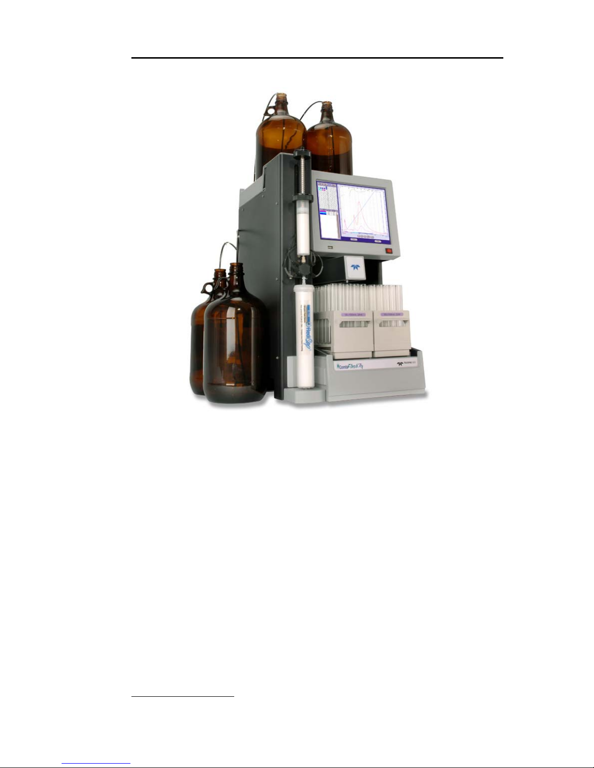
The Teledyne Isco CombiFlash Rf flash chromatography
system gives you high-productivity automation,
programmable gradients, full-spectrum UV detection and
peak separation, and automatic detection of columns and
collection tube racks. Its small size makes it a great “personal
system” and well suited for operation within chemical hoods
and other limited spaces.
WARNING
Avoid hazardous practices! If you use this instrument in any
way not specified in this manual, the protection provided by
the instrument may be impaired; this may increase your risk
of injury.
CombiFlash® Rf Installation Guide
1-2
Figure 1-1 CombiFlash Rf
Control of the system is through a simple to use interface. This
interface can be accessed through the touch screen panel, or a
Windows computer via a direct or network Ethernet
connection. These options give you the flexibility to operate
and monitor the CombiFlash R
f
system at the instrument,
from a computer in the lab, or from remote locations.
The CombiFlash R
f
is optimized for use with Teledyne Isco’s
RediSep
®
Rf columns, which are pre-packed with a variety of
media. For example, the CombiFlash R
f
can purify samples
from 4 milligrams to greater than 33 grams using RediSep R
f
columns loaded with 4 to 330 grams of silica gel.
Applications include purification of organic compounds for
drug discovery, as well as research in agrochemicals,
petrochemicals, natural products, polymers, and catalysts.

Section 1 Introduction
1-3
1.3 Operating Overview
The CombiFlash Rf may be controlled through its built-in
touch screen panel or by a Windows computer running
Microsoft Internet Explorer 6 or newer.
The CombiFlash R
f
is equipped with the touch screen display
for local control. For Windows computer control, the
CombiFlash R
f
may be controlled by the computer in two
different ways using TCP/IP protocol—direct or network. A
direct connection uses a cross-over cable between Ethernet
ports on the CombiFlash R
f
and computer. A network
connection allows control from a computer on an established
network.
Note
Teledyne Isco recommends that you obtain assistance from your
Information Technology department before attempting direct or
network connections to a Windows computer.
1.3.1 Multiple Control Possibilities
The system can be accessed from the built-in touch panel and
up to ten network computers. The touch panel shares control
with all connected computers. The system performs the most
recent command from any control input.
1.3.2 File Storage
To support operation from a variety of direct and network
connections, the software and all files are stored in the
CombiFlash R
f
on an internal hard drive. This ensures that
your compound purification methods and run history files can
be viewed from any connection.

CombiFlash® Rf Installation Guide
1-4
1.4 Specifications
Table 1-1 Specifications
1
Overall Dimensions Height: 61 cm (24")
Width: 36 cm (14.1")
Depth: 43 cm (17")
Weight 24.5 kg (54 lbs)
Power Options
Input voltage range from 100 to 240 VAC, 2.0
Amps maximum
Line Frequency 50/60 Hz
Ambient Temperature 20 to 40°C (maximum temperature must be
at least 15°C below the boiling point of the
solvent)
Humidity (when
connected to power)
95% relative humidity maximum at 20 to
40°C
Flow Rate Range 5 to 100 ml/min
Flow Rate Accuracy ±5%
Pressure Limit Up to 200 psi (column dependant)
For columns undetected by RFID, the
maximum pressure is limited to 50 psi.
Pressure Accuracy 5% of full scale
Peak Detection Modes Slope or threshold
UV Spectrum 200 to 360 nm
Wavelength Accuracy ±5 nm
Flow Cell Pathlength 0.1 mm, ±25%
Fraction Accuracy ±[2ml + (flow rate ÷ 60)]
Pollution Degree 2
Electrical Safety per EN 61010-1
Installation Category II
Maximum Altitude 2000 meters
Note 1. All specifications are preliminary and subject to change.
Section 1 Introduction
1-5
1.5 Controls, Indicators, and Features
Figures 1-2 through 1-4 illustrate the controls on the
CombiFlash R
f
.
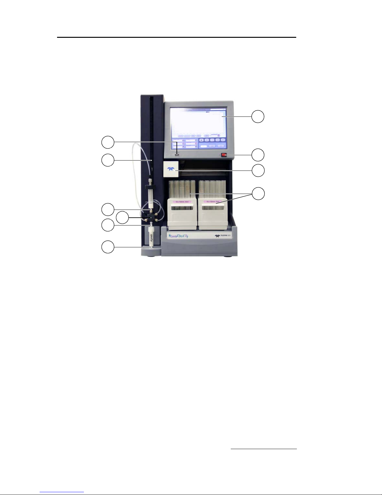
Figure 1-2 CombiFlash R
f
Features (Front)
1. Touch Panel LCD display – Large 10.5 inch display for
system monitoring and control.
2. USB Port – Convenient, front panel port that accepts USB
Flash memory drive. A Flash memory drive may be
inserted into this port for transferring files, importing and
exporting methods, and system software updates.
3. Adjustable Column Mount – The injection valve
assembly and upper column mount slide along this mount
so the system can accept a variety of column sizes.
4. On/Standby Switch – 1 = On, 0 = standby.
5. Fraction Collector Arm and Drop Former – The arm
and drop former move to deposit liquid in the collection
tubes.
3
4
1
5
6
7
8
9
10
2

CombiFlash® Rf Installation Guide
1-6
6. Racks and Collection Tubes – The racks hold the
fraction collection tubes. Racks include an RFID tag which
the system uses to read the rack type and collection tube
size.
7. Sample Injection Port – Luer-type fitting to accept the
sample though either a solid load sample cartridge (shown)
or a liquid injection using a syringe or similar device.
8. Injection Valve – This six-way valve is automatically
positioned by the CombiFlash R
f
according to its current
mode of operation. Modes include column equilibration,
sample injection, elution, column flushing, valve cleaning,
and system purging.
9. Upper Column Mount – Secures the column inlet.
10.Lower Column Mount – Secures the column outlet.
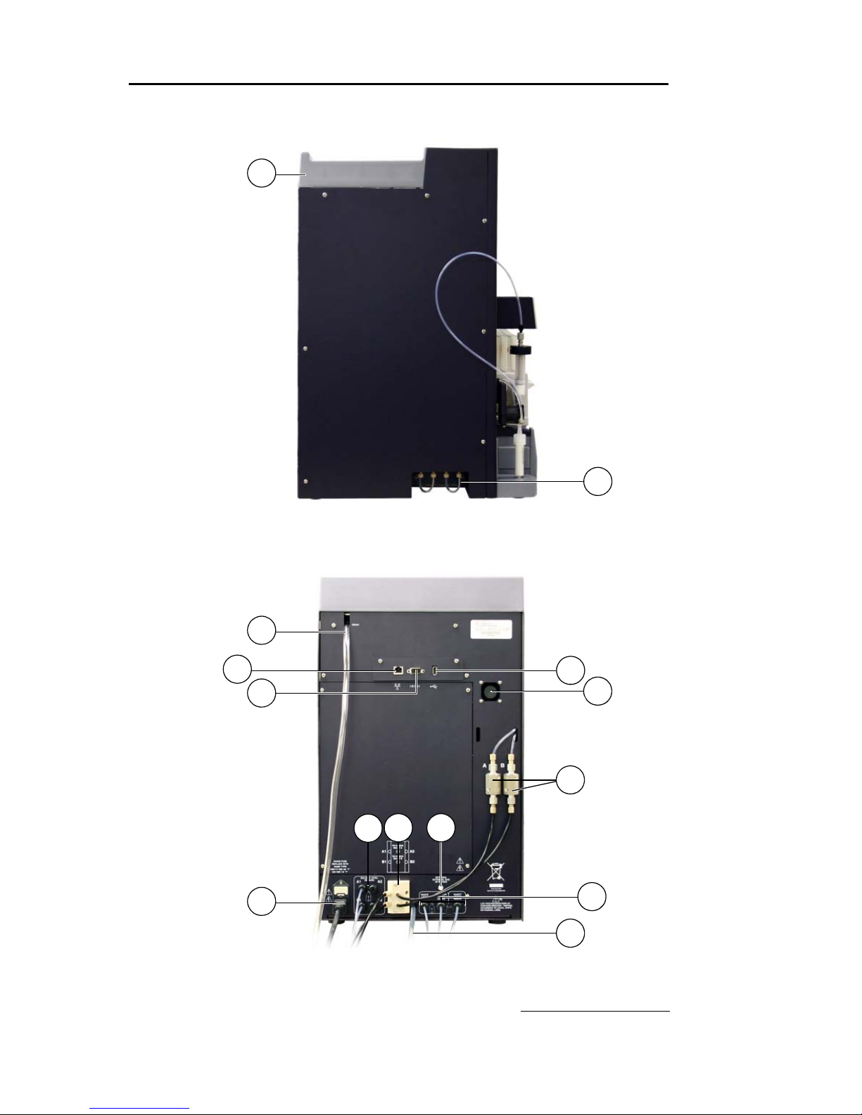
11.Top Shelf – Allows storage of accessories and solvent
bottles.
12.Column Expansion Ports – These ports allow the system
to add column channels with an optional module. This
option is not available at the time of printing.
13.Upper Drain Tube – Liquids spilled on the top shelf are
carried away through this tube to a user-supplied
container.
14.Ethernet Port – An 8P8C jack for a network connection
using a standard CAT5 cable, or for a direct connection to a
computer using a cross-over cable.
15.RS-232 Port – Serial communication port to interface with
expansion modules.
16.USB Port – For control of peripheral equipment. This rear
panel port is primarily for service-related functions.
17.Cooling Fan – Cools the internal electronic assemblies.
18.Check Valves – Externally-mounted pump check valves to
simplify pump maintenance.
19.Solvent Level Sensing Outlet Ports – uses air or
user-supplied gas to measure the hydrostatic pressure of
the solvent above the weighted tubing outlet.
20.Solvent Inlet Ports – Accepts two A solvents and two B
solvents.
Section 1 Introduction
1-7
Figure 1-3 CombiFlash Rf Features (Side)
Figure 1-4 CombiFlash R
f
Features (Back)
11
12
19
20
23
16
13
14
15
22
21
18
24
17

CombiFlash® Rf Installation Guide
1-8
21.Optional External Gas Port – An inlet for an internal
pump which supplies pressurized air or user-supplied gas
for solvent level sensing, waste container full detection,
and system/column purges. The external gas should be
regulated to 2–5 psig before connecting the source to this
port.
22.Mains Power – Connects the system to AC line voltage.
23.Was te Po rts – From left to right:
• Waste Level S ense – The system uses air or
user-supplied gas to measure the hydrostatic
pressure of the waste above the level sense line end.
The system will suspend operation when this level is
too high.
• Diverter Valve Waste – The diverter valve on the
fraction collector arm sends fluid to this waste port.
• Inject Valve Waste – The injection valve is cleaned
after each run. The system directs fluids from this
automatic cleaning routine to this port.
24.Lower Drain Tube – This tube carries away liquids
spilled onto the rack area.
1.6 Safety
Before installing, operating, or maintaining this equipment, it
is imperative that all hazards and preventive measures are
fully understood. While specific hazards may vary according to
location and application, take heed in the following general
warnings:
WARNING
Liquids associated with this instrument may be classified as
carcinogenic, biohazard, flammable, or radioactive. Should
these liquids be used, it is highly recommended that this
application be accomplished in an isolated environment
designed for these types of materials in accordance with
federal, state, and local regulatory laws, and in compliance
with your company’s chemical/hygiene plan in the event of a
spill.
Section 1 Introduction
1-9
WARNING
Avoid hazardous practices! If you use this instrument in any
way not specified in this manual, the protection provided by
the instrument may be impaired.
WARNING
If you are using flammable solvents or chemicals with this
system, vapor concentration levels may exceed the maximum
exposure levels as recommended by OSHA Guide 1910.1000.
To reduce those levels to a safe exposure, Teledyne Isco
recommends that you place the system in a laboratory hood
designed for the purpose of ventilation. This hood should be
constructed and operated in accordance with federal state and
local regulations. In the event of a solvent or chemical spill,
your organization should have a plan to deal with these
mishaps. In all cases, use good laboratory practices and
standard safety procedures.
1.6.1 Hazard Severity Levels
This manual applies Hazard Severity Levels to the safety
alerts. These three levels are described in the sample alerts
below.
CAUTION
Cautions identify a potential hazard, which if not avoided, may
result in minor or moderate injury. This category can also warn you
of unsafe practices, or conditions that may cause property
damage.
WARNING
Warnings identify a potentially hazardous condition, which if
not avoided, could result in death or serious injury.
DANGER
DANGER – limited to the most extreme situations to identify
an imminent hazard, which if not avoided, will result in
death or serious injury.
CombiFlash® Rf Installation Guide
1-10
1.6.2 Hazard Symbols
The equipment and this manual use symbols used to warn of
hazards. The symbols are explained in Table 1-2.
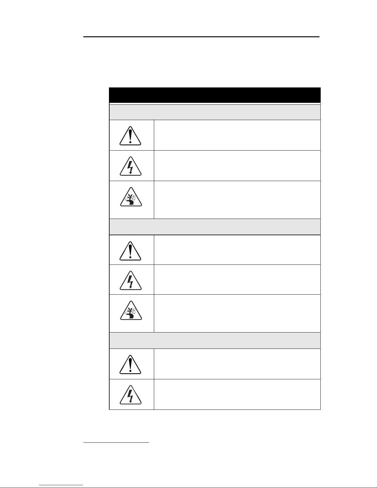
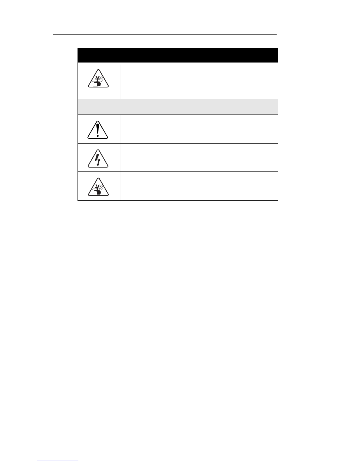
Table 1-2 Haza rd Symb ol s
Warnings and Cautions
The exclamation point within the triangle is a warning
sign alerting you of important instructions in the
instrument’s technical reference manual.
The lightning flash and arrowhead within the triangle is a
warning sign alerting you of “dangerous voltage” inside
the product.
The pinch point symbol warns you that your fingers or
hands will be seriously injured if you place them
between the moving parts of the mechanism near these
symbols.
Symboles de sécurité
Ce symbole signale l’existence d’instructions
importantes relatives au produit dans ce manuel.
Ce symbole signale la présence d’un danger
d’électrocution.
Risque de pincement. Ces symboles vous avertit que
les mains ou les doigts seront blessés sérieusement si
vous les mettez entre les éléments en mouvement du
mécanisme près de ces symboles
Warnungen und Vorsichtshinweise
Das Ausrufezeichen in Dreieck ist ein Warnzeichen, das
Sie darauf aufmerksam macht, daß wichtige
Anleitungen zu diesem Handbuch gehören.
Der gepfeilte Blitz im Dreieck ist ein Warnzeichen, das
Sei vor “gefährlichen Spannungen” im Inneren des
Produkts warnt.
Section 1 Introduction
1-11
1.7 For Additional Information
Technical assistance for the CombiFlash Rf can be obtained
from:
Teledyne Isco, Inc.
4700 Superior St.
Lincoln NE 68504
Phone: (800) 228-4373 or (402) 464-0231
Fax: (402) 465-3001
E-mail: IscoService@teledyne.com
Vorsicht Quetschgefahr! Dieses Symbol warnt vor einer
unmittelbar drohenden Verletzungsgefahr für Finger und
Hände, wenn diese zwischen die beweglichen Teile des
gekennzeichneten Gerätes geraten.
Advertencias y Precauciones
Esta señal le advierte sobre la importancia de las
instrucciones del manual que acompañan a este
producto.
Esta señal alerta sobre la presencia de alto voltaje en el
interior del producto.
Punto del machacamiento. Sus dedos o manos seriusly
serán dañados si usted los coloca entre las piezas
móviles cerca de estos símbolos.
Table 1-2 Hazard Symbols (Continued)

2-1
CombiFlash® R
f
Installation Guide
Section 2 System Preparation
This section provides instructions for unpacking and installing
the CombiFlash R
f
system. To prepare the system for
operation, sequentially follow all instructions in sections 2.1
through 2.12.
2.1 Unpacking the Unit
The CombiFlash Rf is shipped in a single carton. Carefully
unpack the shipment and inspect the contents. If there is any
damage to the shipping carton or any components, contact the
shipping agent and Teledyne Isco (or its authorized
representative) immediately.
WARNING
If there is any evidence that the system has been damaged in
shipping, do not plug it into AC power. Contact Teledyne Isco
or its authorized representative for advice.
Compare the contents of the boxes with the enclosed packing
slip. If there are any shortages, contact Teledyne Isco
immediately.
2.2 Instrument Location
The CombiFlash Rf has a relatively small footprint, requiring
about 1550 square centimeters (240 in
2
) of level bench space.
Ensure that the CombiFlash R
f
has at least 3 cm (1.25") of air
space behind it for ventilation. Additional space may be
required for solvent and waste containers.
Refer to Table 1-1 for environmental conditions and power
requirements.
CombiFlash® Rf Installation Guide
2-2
WARNING
The system is heavy. Use a two-person lift to prevent injury.
Before making any connections to the CombiFlash Rf, place
the system on the bench or in the fume hood where it will be
operated. Temporarily position the system so you can access
the back panel to complete the connections.
2.3 Connect Power
Ensure that the On/Standby switch below the touch screen
panel is in the Standby position. Then, use the supplied IEC
power cord to connect the CombiFlash R
f
to mains power.
WARNING
Mains power must meet the voltage, frequency, and amperage
requirements listed on the serial number label.
2.4 Connect Solvent Lines
WARNING
Risk of fire ignited by electrostatic discharges. Never
substitute the black tubing on CombiFlash systems. The black
PTFE tubing (P/N 023-0503-06) is conductive. This tubing is
required to dissipate static electricity.
CAUTION
To prevent damage or premature wear to the pump and internal
valves, clean solvent should be used. The solvent should not
contain any dissolved solids.
The CombiFlash Rf has four solvent inlet ports on the back
panel: two A solvents and two B solvents. The system requires
at least one A and one B solvent to form a binary gradient, and
assumes that the B solvent is stronger than A. The second set
of inputs allow you to form alternative binary gradients, or
change the A or B solvent mid-run.
Accessory package (P/N 60-5239-006) includes several pieces
to complete the solvent inlet connections.
Section 2 System Preparation
2-3
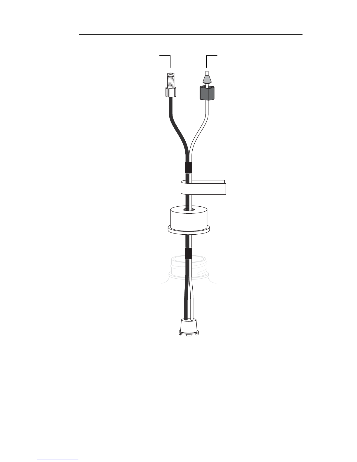
Figures 2-1 and 2-2 show the recommended connections when
the user-supplied solvent container has a 38 or 45 mm opening
(GL 38 or GL 45). Note that there are two different styles that
can ship with the system. One styles includes a metal plate
and larger opening on the cap (Figure 2-1), the other has no
plate and a smaller opening on the cap (Figure 2-2).
Figure 2-1 Recommended solvent connection, with plate
60-0923-017 Ferrule
60-0923-015
Compression Fitting Nut
60-5234-130
Label (1 of 4)
60-5235-042 38 mm Cap, or
291-0010-06 45 mm Cap
60-5233-399 38 mm Plate, or
60-5233-400 45 mm Plate
60-5234-129
Inlet Filter Assembly
(Place weighted filter at
bottom of container.)
To Solvent Level SensingTo Solvent Supply
Connection
CombiFlash® Rf Installation Guide
2-4
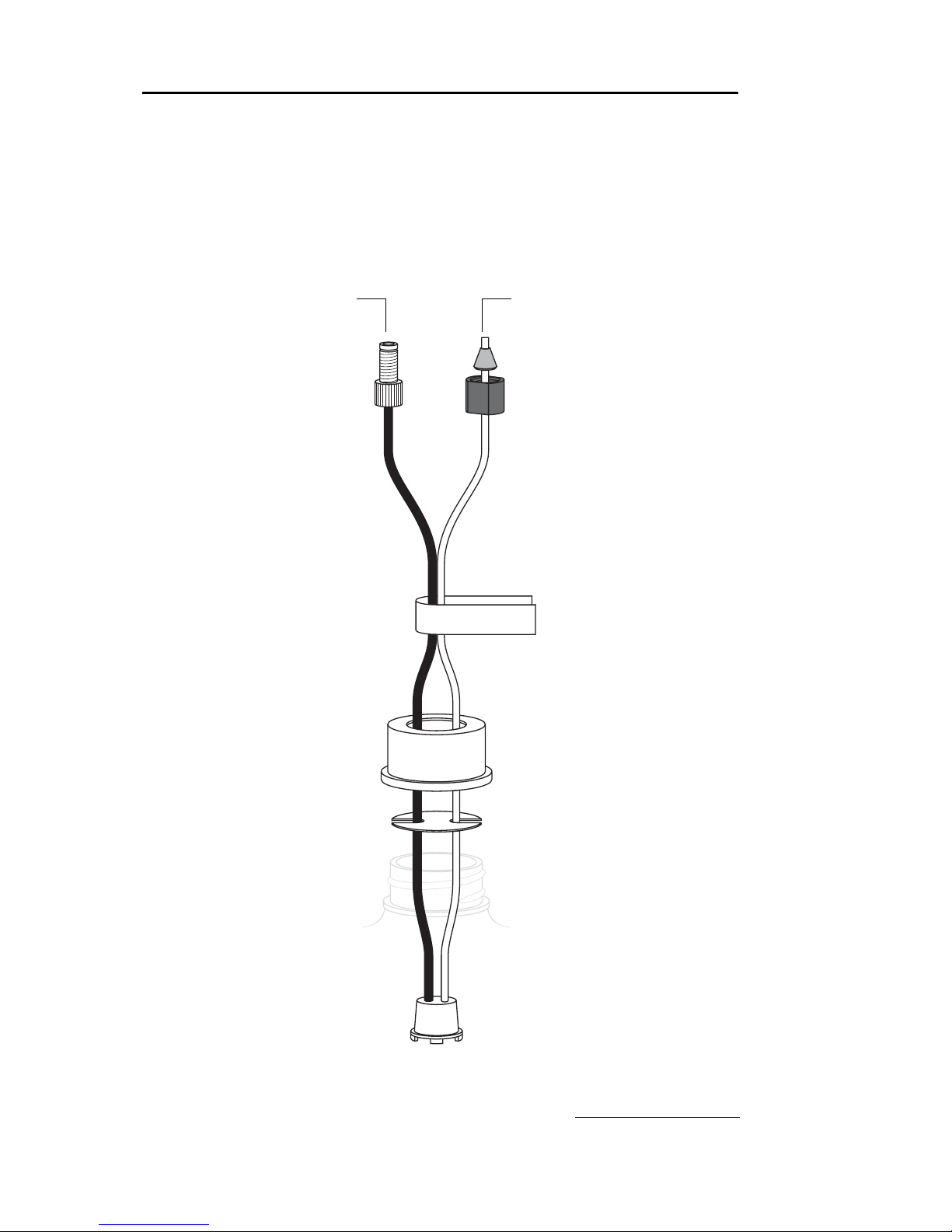
Figure 2-2 Recommended solvent connection, without plate
If the container does not have a GL 38 or GL 45 opening, omit
the use of the cap and plate. Ensure that the solvent and air
tubing are secured so that the weighted filter remains at the
bottom of the solvent source.
60-0923-017 Ferrule
60-0923-015
Compression Fitting Nut
60-5234-130
Label (1 of 4)
60-5235-050 38 mm Cap, or
60-5235-051 45 mm Cap
60-5234-129
Inlet Filter Assembly
(Place weighted filter at
bottom of container.)
To Solvent Level SensingTo Solvent Supply
Connection
Section 2 System Preparation
2-5
The Solvent Level Sensing air line connects to the back panel
with a compression fitting. This fitting must be airtight. To
connect tubing using the compression fittings:
1. Slide the nut and ferrule onto the tubing as shown in
Figure 2-1 or 2-2.
2. Fully insert the tubing into the threaded bulkhead fitting
on the back panel of the system.
3. Finger-tighten the nut onto the threaded bulkhead fitting.
This will seat the ferrule in the fitting.
Note
When using higher-density solvents such as dichloromethane
(DCM), place the solvent container level with or above the
CombiFlash Rf system. Placing solvent containers below the level
of the Rf can contribute to decreased flow due to the high vapor
pressure of DCM. This problem becomes more pronounced as the
ambient temperature increases.
2.5 Connect Waste Lines
WARNING
Risk of fire or equipment damage. Failure to connect Waste
Port tubing may allow organic solvents to pool in unsafe areas,
possibly creating dangerous levels of flammable vapors.
WARNING
Risk of fire ignited by electrostatic discharges. Never
substitute the black tubing on CombiFlash systems. The black
PTFE tubing (P/N 023-0503-06) is conductive. This tubing is
required to dissipate static electricity.
CAUTION
Elevated flammable vapor levels are possible. Ensure that the
waste container is adequately ventilated, preferably by placing it in
a fume hood.
The system has two waste outlets on the back panel: Diverter
Valve waste and Inject Valve waste. You can route waste to a
common collection container, or to individual containers.

CombiFlash® Rf Installation Guide
2-6
The Waste Level Sense uses air pressure to detect the liquid
level in the common waste container. If using individual
containers, use the waste level sense to detect the level of the
Diverter Valve waste container. Under normal operating
conditions it will fill faster than the Inject Valve waste
container. Empty both containers at the same time to prevent
overfilling the unmonitored container.
Accessory package (P/N 60-5239-006) includes parts to
complete the waste connections. Figure 2-3 shows the
recommended connections for user-supplied waste containers
with either a 38 or 45 mm opening (GL 38 or GL 45). Note that
there are two different styles that can ship with the system.
One styles includes a metal plate (Figure 2-3), the other has a
plastic plate with four small openings on the cap (Figure 2-4).
Refer to the steps in section 2.4 to connect the tubing to the
system using the compression fittings. Then, complete the
connections according to Figure 2-3 or 2-4.
If your connection hardware matches Figure 2-3, connect the
Waste Level Sense line to the compression fitting in the center
of the cap. Push the ends of the two black waste lines through
the holes in the cap.
If your connection hardware matches Figure 2-4, push the
three tubes through the cap. Push the stop on the Waste Level
Sense tubing against the cap. This ensures that the Waste
Level Sense tubing is far enough into the container to detect
when it is nearly full.
Should the container not have a GL 38 or GL 45 opening, omit
the use of the waste cap. Ensure the solvent tubes are secured
so they drain into the waste container. Secure the Waste Level
Sense air tubing so its outlet is at least two inches (5 cm)
below the container’s maximum level.
Note
When using higher-density solvents such as dichloromethane
(DCM), ensure that the waste container is no more than 3 feet
below the supply solvent levels. Placing solvent containers above
the system and waste containers on the floor may cause the
internal check valves to open and allow solvent to flow through the
system when in the standby state.

Section 2 System Preparation
2-7
Figure 2-3 Recommended waste connections, with metal plate
60-0923-017 Ferrule
60-0923-015
Compression Fitting Nut
60-5234-143
Waste Tubing Assembly
60-5234-051 38 mm Waste Cap, or
60-5234-142 45 mm Waste Cap
To Diverter Valve Waste
Connection
To Waste Level
Sense Connection
To Inject Valve Waste
Connection

CombiFlash® Rf Installation Guide
2-8
Figure 2-4 Recommended waste connections, with plastic plate
60-0923-017 Ferrule
60-0923-015
Compression Fitting Nut
60-5234-143
Waste Tubing Assembly
60-5235-053 38 mm Waste Cap, or
60-5235-054 45 mm Waste Cap
To Diverter Valve Waste
Connection
To Waste Level
Sense Connection
To Inject Valve Waste
Connection
Tubing Stop
Ventilation Hole
(Luer fitting)
If necessary, connect
user-supplied tubing and
route to fume hood.

Section 2 System Preparation
2-9
2.6 Optional External Gas
The CombiFlash Rf system has an internal air pump that
provides compressed air for solvent and waste level sensing.
Optionally, the system can deliver a compressed gas. Inert or
other gases may be more suitable than air for some
applications.
If ambient air is compatible with your solvents and waste,
simply leave the Optional External Gas port open.
If you want to use a gas instead of air, connect user-supplied
1
/8" I.D. tubing to the Optional External Gas port. Connect the
other end to the user-supplied compressed gas. The external
compressed gas should be dry, filtered, and regulated to 2– 5
psi (0.14–0.34 atm, 13.8 –34.5 KPa).
2.7 Connect and Route Drain Lines
WARNING
Risk of fire or equipment damage. Failure to connect drain lines
may allow organic solvents to pool in unsafe areas, creating a
potential for dangerous levels of flammable vapors. Improper
draining may damage the instrument’s internal components.
The CombiFlash Rf has drain tubes extending from its top
shelf and back panel. The tubes drain away any liquid spilled
on the top shelf and the tray beneath the fraction collection
racks. Route the end of this tubing to a suitable waste fluid
collection container.
Note
It may be necessary to extend the drain tube. If so, splice the
tubing with user-supplied tubing. The user-supplied tubing should
have an inside diameter no smaller than the existing drain tubing,
and must be compatible with the solvents used by the system.
Route this extension tubing to the waste collection vessel.
2.8 Position the System
After completing the various connections, the system can be
moved to its operating position. Turn the system so that the
operator can access all of the front view features and controls
(Figure 1-2). Use care not to damage the connections, tubing,
and cables while moving the system.

CombiFlash® Rf Installation Guide
2-10
2.9 Install Collection Tube Racks
Before beginning a run, you must load collection racks with
tubes onto the system’s fraction collector tray.
Your system was shipped with two collection tube racks. The
following tube rack sets are available:
• 60-5237-031 – Two racks for 16×125 mm test tubes
(15.5 mL). Total tubes: 150.
• 60-5237-032 – Two racks for 16×150/160 mm test
tubes (18 mL). Total tubes: 150.
• 60-5237-033 – Two racks for 18×150 mm test tubes
(25 mL). Total tubes: 140.
• 60-5237-034 – Two racks for 18×180 mm test tubes
(30 mL). Total tubes: 140.
• 60-5237-035 – Two racks for 25×150 mm vials
(50 mL). Total vials: 60.
• 60-5237-040 – One rack for 500 mL French square
bottles.
To load the racks:
1. Insert test tubes, vials, or bottles into the rack (Fig. 2-5).
CAUTION
Risk of broken glass or equipment damage. Do not load test tubes
longer than the length listed on the tube size label.
2. While holding the rack with the tube size label visible
(Figure 2-6), insert the racks into the system. Slide the
rack in until you feel it drop into its seated position.
CAUTION
An incorrectly installed rack will cause the rack to be misaligned
under the fraction collector arm. Misaligned racks might cause
fractions to miss the tube opening or deposit in the wrong tube.
Always ensure the tube size label is visible (that is, facing outward)
and the rack is pushed in until it is seated.

Section 2 System Preparation
2-11
When you turn the power switch to on, the system will
automatically detect the type of rack, and configure program
settings accordingly. Later, in section 2.11.6, you can configure
the maximum volume for each tube size.
Figure 2-5 Loading test tubes
Figure 2-6 Inserting the collection tube rack
Tube Size
Label

CombiFlash® Rf Installation Guide
2-12
2.10 Turn on Power
The system’s power switch is located just below the touch
screen panel. Turn the switch to the ON position. The system
will begin its startup routine which includes self diagnostics.
The system is ready for operation when the PeakTrak screen
is displayed.
2.11 Configure the System
Before operating the system, it should be configured for the
desired operation. To configure the system, open the
Configuration window by selecting Tools>Configuration from
the PeakTrak menu.
The configuration window has two tabs: Instrument
Configuration and Network Configuration. Adjust the
following (sections 2.11.1 through 2.11.9) on the Instrument
Configuration tab for the desired operation and then click OK
to save the settings. Network Configuration settings are
discussed later in Section 4, Remote Interfaces.
2.11.1 Solvents
When you installed the system, up to four solvents were
connected to the back panel. This section of the Configuration
window allows you to manage these solvents. To do so:
Note
The system is shipped with common solvent names already
loaded. If your solvent names are listed in the solvent drop-down
list boxes, skip steps 1 through 3.
1. Click the “Add Solvent” button.
2. Enter the solvent name and click the OK button.
3. Repeat steps 1 and 2 for all four solvents.
4. For the Solvent A1 drop-down list box, select the solvent
name connected to the A1 Solvent Inlet Port. Repeat for
Solvents A2, B1, and B2.
5. Select the “Enable solvent level sensing” check box to
enable this feature (recommended). Clear this box to
disable this feature.

Section 2 System Preparation
2-13
The solvent level sensing feature will monitor solvent
usage to minimize the risk of running out of solvent during
a purification run. The system compares the volume
required for a purification run with the estimated volume
in the solvent container and alerts you when there is not
enough.
6. If using the solvent level sensing feature, enter the
Minimum Solvent Level (density dependent) as a range in
centimeters.
To understand this range, consider that dichloromethane is
more dense than hexane. If the selected range is 2–4, the
system triggers an alert when the dichloromethane level
falls to about 2 cm above the weighted filter. At the same
selected range, the system would trigger an alert when the
hexane falls to about 4 cm above the weighted filter.
2.11.2 General Settings
CombiFlash Rf Name (optional) – Use this option to name
your system. The name will appear in operational displays
and run summaries. This feature is useful when your
laboratory has more than one CombiFlash R
f
system.
Language – Select the desired language from the drop-down
list box.
2.11.3 Vapor Limit
The system has an internal vapor sensor that detects vapors
present in the immediate atmosphere. When the limit is
exceeded, the CombiFlash R
f
will shut down to avoid a
hazardous condition.
Teledyne Isco recommends using the default setting of 25.
This value represents an organic vapor level slightly above the
ambient vapor level of a well-ventilated laboratory.
A setting below 25 could cause random alarms without
significant vapors present. If PeakTrak displays a Vapor Limit
alarm while the Vapor Limit is set at 25, perform the following
checks on your laboratory and the instrument:
• Ensure that no open containers or spills of organic
solvent are in close proximity to the system.
• Ensure that the system is located in a well-ventilated
area.

CombiFlash® Rf Installation Guide
2-14
• Ensure that there is no visible solvent leakage from the
system.
If PeakTrak continues to display the Vapor Limit alarm after
you have made these checks and corrected any problems
found, it is likely that organic vapors are present in the ambient environment of your laboratory. In this case, increase the
setting of the Vapor Limit. Settings greater than 25 are appropriate for laboratory environments with a somewhat elevated
background solvent vapor concentration, representing a safe
setting, but one with a reduced margin for error.
2.11.4 Automatically Print Report at End of Run
If this option is enabled, the system will print a report at the
end of each run.
Note
This option requires the system to configured for network
operation and a connection to a printer on the network. Network
settings are discussed in Section 4, Remote Interfaces. Do not
select this option for these initial installation steps.
2.11.5 Enable Run Length Extension
When enabled, this option automatically extends the run if a
peak is eluting at the end of the maximum %B gradient. This
ensures that a late-eluting peak fully comes off the column
and is collected.
An automatic run extension is a five-minute isocratic hold
added to the end of the run’s maximum %B gradient profile.
During the extension, the system continues to pump the
maximum %B solvent mixture. Should the system still detect
a peak after an extension, the system will add another, up to a
maximum of three extensions.
Occasionally, compounds might come off the column once the
%B returns to the minimum value at the end of a run. If the
Run Length Extension is enabled, it will automatically extend
the run one time to clear the column and plumbing of any
remaining material.

Section 2 System Preparation
2-15
Figure 2-7 Automatic Run Extension Examples
Figure 2-7 illustrates the possible run extensions. The original
method was programmed to rise to the maximum %B over
seven minutes, hold for two minutes and return to the
minimum %B for a final minute. At nine minutes, a peak was
eluting. The system extended the run, holding the %B at the
maximum level for another five minutes. This also occurred at
fourteen and nineteen minutes, resulting in the second and
third extensions. At 24 minutes, the %B solvent strength
returned to zero. Before the final minute elapsed, more
compound was detected, causing the system to extend the run
for a final five minutes at the minimum %B.
2.11.6 Set Default Tube Volumes
Click this button to open a window from which you can set the
default volume of the collection tubes. You can increase or
decrease these values to set the desired default volume
collected in each container. Just be sure you don’t overflow the
containers by exceeding their capacity.
The system will automatically advance to the next tube when
this default volume is met in each tube. Keep in mind that
advanced method settings (discussed in Section 3 and the
on-line help) may override this default setting. During a run,
other factors such as automatic tube advances for detected
peaks will affect collected volume.
2.11.7 Set Date/Time
Click this button to open a window from which you can set the
system date and time.
0 5 10 15 20 25
Original method
Extension 1
Extension 2
Extension 3
Final Extension
Minutes

CombiFlash® Rf Installation Guide
2-16
To prevent unauthorized time changes, this feature is
password protected. The system is shipped with the password
set to combiflash. Use the Tools>Set Password menu
command to change this password for greater security.
2.11.8 Default Run Units
Run units are displayed along the X-axis of the chromatogram.
Select Time (in minutes) or Column Volumes. A column
volume unit is the time it takes to pump enough solvent to
exchange the volume held by the column. The duration in
minutes will vary according to the column media and size, and
the flow rate.
2.11.9 Gradient Method
Select the standard gradient type (Figure 2-8).
• Linear – The system gradually mixes solvents A and B
from the last programmed %B until it reaches the next
programmed %B. This method connects the inflection
points that define the gradient with a straight line.
• Step – The system holds each %B value until it reaches
the next programmed %B. Because the system holds the
%B values, the changes at each new value are nearly
instantaneous, producing a stepped appearance on the
plot area.
• Isocratic – The system holds the initial solvent mix for
the entire run.
Figure 2-8 Gradient types
IsocraticStepLinear

Section 2 System Preparation
2-17
2.12 Prime the Solvent Lines
Before the first use, the system should be primed. Ensure that
the solvent containers are filled, then:
1. Select the “Tools>Auto prime” menu command.
2. Select the desired A and B solvents from the drop-down list
boxes.
3. Click the Play button to start priming the system.
The system pumps 100% Solvent B through the system and
out the Waste port, and then repeats with 100 % Solvent A.
(This B-A order leaves the internal lines filled with solvent
more appropriate for the beginning of a purification run.)
Note
When priming the first time, inspect the solvent and waste
connections to the system. If any leaks are observed, click the
Cancel button to stop the Auto Prime. Correct the leak by
tightening the fitting an additional
1
/4 turn, and then restart the Auto
Prime from step 1.
To advance to the next Auto Prime step, you can click the
Fast Forward button. The Auto Prime window closes when
finished.
After Auto Priming, the system is ready for operation
(Section 3).
Note
Use Auto Prime for quick solvent changes by pumping a fixed
amount of solvent through the waste fluid path at 100 mL/min. For
more advanced priming functions such as varying the flow rates,
fluid paths, etc., or to purge the system with air before changing
between normal and reversed phase solvent systems, use the
Tools>Manual Control option.

3-1
CombiFlash® R
f
Installation Guide
Section 3 Operation
This section provides abbreviated operating instructions for
the CombiFlash R
f
. For complete instructions, refer to Help
menu option from PeakTrak’s main menu.
3.1 Sample Preparation
Before starting a run, consider how the sample will be
introduced to the column media. This section discusses three
methods: liquid injection, solid sample cartridges, and
preloading the sample on the column.
3.1.1 Liquid Sample Injection
If the sample is soluble in the starting mobile phase, it can be
prepared as a solution and injected onto the column when
prompted during the purification run.
3.1.2 Solid Samples
Some compounds are not soluble in solvents that are
compatible with the chromatography. In addition, the
compounds may have very limited solubility in any solvent,
resulting in sample volumes that are impractical for good
chromatography. The solution in this case is solid sample
introduction. Here the reaction mixture or dissolved sample is
mixed with the same media in the chromatography column.
Some samples of this type may be simply dissolved and placed
into a prefilled cartridge. You can then use the cartridge
immediately, or dry it by vacuum before placing it on the
system.
Other samples may need more care. Typically you would
create a mixture of 20% sample load to media (w/w). Then dry
the mixture under conditions that will drive off the solvent
without affecting the compounds of interest. These compounds

CombiFlash® Rf Installation Guide
3-2
remain bound to the media. Once dried, pour the
media/sample mixture into an empty cartridge.
To prepare an empty solid sample cartridge:
1. Ensure the empty cartridge has a bottom frit.
CAUTION
Missing frits may cause equipment damage, UV detection
problems, or increased maintenance. Frits prevent solids from
entering the fluid path.
2. Prepare the media and sample:
a. Dissolve your sample in a minimal amount of a suitable,
volatile solvent.
b. Place the media into the solvent. If using silica gel, a
particle size of 40–60 µm (240–400 mesh) is
recommended. The amount of silica required is about
four to five times the mass of your sample.
c. Agitate the solvent for a moment to allow the sample to
adsorb to the silica.
d. Remove the solvent with a suitable method, such as
rotary evaporation.
3. Load the media and sample mixture into the cartridge. Tap
the cartridge on the benchtop to settle the mixture.
4. Place a frit on the top of the cartridge. Force the frit down
against the mixture using the plastic plunger.
5. Wipe any residual powder inside the neck of the cartridge.
Empty solid sample cartridges also allow a variety of
adsorbents, such as diatomaceous earth, boiling chips, cotton
balls, or paper wipes. Even with alternative adsorbents,
always use top and bottom frits to prevent fluid path
problems.
After you have prepared the pre-filled or empty cartridge,
place the solid sample cartridge on the system:
1. Attach the desired adjustable cartridge cap to the system.
2. Align the cap and cartridge and push them together.
3. Rotate the cartridge
1
/4 turn so that the cap will hold the
cartridge.

Section 3 Operation
3-3
4. Press the tab on the cap and push the plunger into the
cartridge until it rests against the top frit.
5. Release the tab on the cap. Note that the opposite end of
the tab secures the cartridge.
6. Load the solid sample cartridge with cap on the sample
injection port.
3.1.3 Preloading on Column
You can load the reaction mixture or sample directly onto the
column, sometimes called “direct” or “dry” loading.
Note
If using this method, use care to ensure that a column equilibration
does not wash away the sample. Bypass the column equilibration
at run time by selecting “Preload on column” as the sample
Loading Type. Refer to Section 3.3 for more details.
3.2 Loading a RediSep Rf Column
To loa d a RediSep Rf column:
Note
For best results, always use RediSep Rf columns. The system will
not automatically detect other columns, including non-Rf RediSep
columns. The system also limits the maximum operating pressure
to 50 psi when the column is not detected.
1. Select a RediSep Rf column. The on-line help includes a
column selection guide that can assist you in selecting a
stationary phase media and column size.
2. Raise the injection valve and insert the column into the top
column fitting. Note that the column fittings are keyed to
ensure the correct flow direction.
3. Slowly lower the injection valve while aligning the bottom
column fitting. The spring-loaded injection valve will hold
the column in place.
4. To seal the column fittings, give the column a slight twist
(
1
/4 turn).

CombiFlash® Rf Installation Guide
3-4
Note
After loading a RediSep Rf column, the system will use RFID
technology to automatically detect the media type and column
size. PeakTrak displays the detected column size on the Main and
Method Editor windows. If the system does not detect the column,
manually select the column media and size.
3.3 Start a Default Method
After completing the installation steps in Section 2, preparing
the sample, and inserting the column, you are ready to
perform a run with the default method. The system’s default
methods are factory-set with run parameters typically used by
chemists. Default methods are optimized for the use of
RediSep R
f
columns. The default settings will:
• equilibrate the column
• collect all fluid in the fraction collector rack
• differentiate between UV vs. non-UV absorbing fluid
and place the fluids into separate tubes
• cut UV absorbing peaks based on slope detection or level
threshold.
To start the run from the PeakTrak Main window:
1. Enter a sample name. If you choose not to, PeakTrak will
enter the date and time as the sample name when you start
the run.
2. Review the PeakTrak Main window settings. If you want to
change any settings, refer to the Editing a Method on-line
help topic.
3. Click the Play button.
4. Select the sample Loading Type from the list. This Loading
Type should support the sample preparation you chose in
Section 3.1. Possible sample loading types are:

Section 3 Operation
3-5
• Cartridge w/ (with) pause – Select this option if
you intend place the sample into a solid sample load
cartridge, but have not yet prepared the sample.
When you click the run button, the system will
perform a column equilibration and then wait while
you prepare the cartridge. After you have placed the
cartridge on the system, click OK to continue with the
run.
• Cartridge w/o (without) pause – Select this option
if you have prepared the sample and placed it into a
solid sample load cartridge. The system will proceed
automatically until the end of the programmed run
length.
• Liquid Inject – Select this option if you have
prepared a liquid sample and plan to manually inject
it into the injection port after column equilibration.
• Preload on column – Select this option if you have
preloaded the sample on the column. The system will
skip column equilibration so that the sample will not
be flushed from the column before the run.
5. Review or update the Start Rack and Start Tube.
6. Review the Minimum Run Requirements. The system will
report the estimated solvent volumes, expected waste,
collection tube usage, etc. You can use this information to
verify that there will be enough solvent to complete the
run, the waste volume does not exceed the collection
container’s capacity, and whether or not more tubes will be
required during the run.
Note
The system estimates the solvent volumes by monitoring the
solvent level in the container and the known usage rate. The
system continues to refine this estimate during operation.
Note
If the waste level sensing tube is inserted correctly into the waste
container, the system automatically will suspend operation before
an overflow condition might exist. To prevent the run from being
suspended before completing the run, ensure that the container
will hold the expected waste volume.

CombiFlash® Rf Installation Guide
3-6
7. Click OK and the run begins. The system responds
according to the sample Loading Type you selected in
step 4.
If you selected Cartridge w/ pause, the system equilibrates the column with the starting %B and then waits
while you prepare the solid sample load cartridge. Place the
cartridge on the system and click OK to continue.
If you selected Cartridge w/o pause, the system equilibrates the column and immediately starts the separation.
If you selected Preload on column, the system skips the
equilibration and immediately starts the separation.
If you selected Liquid, the system equilibrates the column
and then waits. When instructed, perform the following
steps:
a. Place the injection syringe on the injection port.
b. Slowly force the liquid into the injection port.
c. Chase the first injection with a second injection solution
of at least 0.25 mL. The chase solution can be the
starting mobile phase or diluted sample mixture.
d. Click OK to continue the run.
3.4 During the Run
You may allow system to proceed with the run while
monitoring the progress on the PeakTrak main window. If
desired, gradient parameters may be modified during the run.
(See the Real-time Gradient Editing on-line help topic.)
As the run progresses, the absorbance trace is drawn on the
Gradient Plot area. The separation or purification continues
until the end of the run defined by the run length setting.

Section 3 Operation
3-7
3.4.1 Run Control Buttons
You clicked the Play button to start the run. During the run,
other run control buttons are active.
• Pause — The Pause button holds the %B at the current
value while the system continues to operate (sometimes
called an isocratic hold). Note that pausing the run
extends the run length. While in the Paused state, you
can resume the run by clicking the Play button, or stop
the run by clicking the Stop button. If you resume the
run, the system continues with the gradient curve at the
%B when the system was paused.
• Stop — This button suspends the entire run. Unlike the
Paused state, the pump, peak detection, and fraction
collection will not operate. While stopped, you can save
the run data by selecting the File>Save Run as PDF or
Save Run as Text from the menu, end the run by clicking
the Rewind button, or resume the run by clicking the
Play button.
• Next Tube — This button advances the fraction
collector to the next tube position. This allows you to
conveniently collect elute of interest in a new tube.
Note
When you click the Next Tube button, the system immediately
marks the tube advance on the chromatogram. However, the
system delays the movement of the drop former over the tubes.
This delay accounts for the volume held in the tubing between the
detector and the drop former, sometimes called the “delay
volume.” It is important to remember that the chromatogram
displays activity in real time while the fraction collector activity lags
behind. The duration of this delay will vary with the flow rate.
• Rewind — This button is active when the system has
completed the run, or if the run was stopped by clicking
the Stop button. The Rewind button returns you to the
Main window with the current method.
If you have stopped the run before its programmed run
length has elapsed, clicking the Rewind button changes the
current method to the new, shorter run length. This modified method is ready for the next run, or can be saved for
future runs.

CombiFlash® Rf Installation Guide
3-8
• Fast Fo rwar d — Click this button to jump to the next
step of a run.
Once you have started a run, the system performs several
steps. The first step is to deliver solvents using the programmed gradient for the entire run length. When this step
is complete, the system will purge the column with air and
clean the injection valve. Clicking the Fast Forward button
will cause the system to skip any remaining time in the
current step and advance to the beginning of the next step.
Unlike the Rewind button, the clicking the Fast Forward
button to complete the run will not modify the current
method’s run length setting.

4-1
CombiFlash® R
f
Installation Guide
Section 4 Remote Interfaces
This section provides instructions for controlling the
CombiFlash R
f
system through a remote interface. The system
can be accessed by several personal computers through a
corporate network, or by a single personal computer (PC)
through a direct connection.
4.1 Network Configuration
Note
The procedures described in this section will require assistance
from your network administrator. Contact your Information
Technology department before proceeding.
The system has a factory-assigned IP address— 192.168.1.51.
In many cases, this address must be reconfigured for use on a
corporate network. To reconfigure the IP address:
1. From the touch screen panel, select the
Tools>Configuration menu command.
2. The Configuration window has two tabs. Select the
Network Configuration tab.
3. Select the Network Type. The options are “Static IP” and
“DHCP”.
Static IP – If you select “Static IP,” configure the IP
Address, Netmask, and Gateway with the information provided by your network administrator.
DHCP – Before considering DHCP, review the three following questions with your network administrator. If you can
answer Yes to all questions, then DHCP is an option for
your system.

CombiFlash® Rf Installation Guide
4-2
• Is it possible to assign a static IP address based on the
MAC address of the instrument? (Administrators may
use this method to assign static addresses through
the DHCP server instead of directly on the
instrument, simplifying the management of static IP
addresses within the organization.)
Note
A label on the system’s back panel lists its MAC Address. You also
can find the MAC Address on the Help>About PeakTrak window.
• Can the DHCP server support an infinite lease for the
instrument?
• Can the DHCP server automatically update the DNS
records after the IP address is given to the
instrument?
If you select “DHCP,” enter a unique Instrument Name.
The name will be sent with the DHCP request and will be
used to update the DNS settings. This name would allow
you to assign an Instrument Name such as “My_Rf.” Users
would then access the instrument through the address
“http://My_Rf.”
4. Click the OK button to save the settings.
5. Confirm that your network administrator has completed
any necessary network changes to support the system.
6. Locate the CAT5 connection cable (P/N 480-6545-01) in the
accessory package. Insert one end into the Ethernet port on
the back panel. Connect the other end of the cable to your
network access port.
You should be able to connect to the CombiFlash R
f
from a PC
on the network (Section 4.1.1) and set up a network printer
(Section 4.1.2).
4.1.1 Network PC Access
A successfully networked CombiFlash Rf system can be
accessed by a PC that meets the recommendations listed in
Table 4-1.
To access the system simply open an Internet Browser and
enter the correct address.

Section 4 Remote Interfaces
4-3
• If the system was configured with an IP address, access
the system from a network computer by entering
“http://___.___.___.___”, where the blanks are replaced by
the selected address.
• If the system was configured for DHCP and a network
name, access the system from a network computer by
entering “http://____________”, where the blank is
replaced by the Instrument Name.
The browser window will load PeakTrak after you enter the
address.
4.1.2 Network Printing
The CombiFlash Rf system can print to a network printer and
supports both JetDirect and line printer (LPR) queues.
Consult with your network administrator to determine the IP
address of selected printer. If the printer uses an LPR print
queue, you must also find out the queue name. If the printer
uses a JetDirect print queue, also ask for the port number.
When this information is known, you can proceed with
configuring system for network printing.
1. Select the Tools>Configuration menu command.
2. The Configuration window has two tabs. Select the
Network Configuration tab.
3. Follow the on-screen instructions for entering the address
and queue information.
Table 4-1 Personal Computer Recommendations
a
Operating Systems: Microsoft Windows 2000, XP, or Vista
Hardware: The computer hardware must meet the minimum
required specifications of the selected operating
system.
Network Protocol: TCP/IP
Network Connection: IEEE 802.3 (Ethernet)
Display: 800 x 600 pixels, 256 colors, minimum
Internet Browser: Microsoft Internet Explorer 6.0 or later.
a. This table shows supported PC configurations. Other configurations or
AJAX-compatible browsers may be possible but are unsupported by Teledyne Isco.

CombiFlash® Rf Installation Guide
4-4
4. Click OK to save the settings. The CombiFlash Rf system
will send a test page to the printer.
After successfully printing a test page, the network printer
will be available for printing using the File>Print menu
command or through the Automatically Print Report at End of
Run feature described below.
4.1.3 Automatically Print Report at End of Run
If the CombiFlash Rf system can successfully print to a
network printer (Section 4.1.2), it may be configured to print a
report at the end of each run. The report includes the method
settings, chromatogram, and peak/tube collection information.
To enable this feature:
1. Select the Tools>Configuration menu command.
2. The Configuration window has two tabs. Select the
Instrument Configuration tab.
3. Select the “Automatically Print Report at End of Run”
option.
4. Click OK to save the setting.
4.2 Direct Connection
A direct connection supports communication between the
CombiFlash R
f
system and a single PC that meets the
recommendations in Table 4-1.
This guide provides instructions for Windows 2000 (section
4.2.1), Windows XP (4.2.2), and Windows Vista (4.2.3). Refer to
the applicable section, then follow the instructions in section
4.2.4 to complete the direct connection.
Note
A direct connection requires a “crossover” CAT5 cable. Standard
CAT5 network cables will not work. You can purchase a crossover
cable locally or ask your Information Technology department to
assemble one. You can also order a crossover cable (part number
480-6545-02) from Teledyne Isco.
Note
These instructions assume that the system is using the factory-set
IP address of 192.168.1.51.

Section 4 Remote Interfaces
4-5
Note
The following instructions may require a user account with
Administrator privileges on the PC. If you cannot modify the
settings in sections 4.2.1 through 4.2.3, contact your Information
Technology department.
4.2.1 Windows 2000 Settings
1. From the Windows Start button, select “Settings>Control
Panel” to view the control panels.
2. Locate the “Network and Dial-up Connections” icon and
open this control panel.
3. Highlight the “Local Area Connection” icon. View the
properties by right-clicking and selecting “Properties.” The
Local Area Connection Properties Window will open
(Figure 4-1).
4. Highlight the “Internet Protocol (TCP/IP)” item in the list,
and click on the “Properties” button. The Internet Protocol
Properties Window will open (Figure 4-2).
Note
The following steps change the local area connection settings. If
the PC must be restored to its original network configuration,
record the present Internet Protocol (TCP/IP) settings now.
5. Click the “Use the following IP address” option.
6. Enter the IP address “192.168.1.200”.
7. Enter the default Subnet Mask “255.255.255.0.”
8. Click the OK button to close the Internet Protocol
properties window. Then, click the OK button to close the
Local Area Connection properties window.
9. Shut down the PC and place the CombiFlash R
f
system in
Standby.

CombiFlash® Rf Installation Guide
4-6
Figure 4-1 Local Area Connection Properties Window
Figure 4-2 Internet Protocol Properties Window
4.2.2 Windows XP Settings
1. From the Windows Start button, open the Control Panel.
2. Locate the Network Connection icon and open this control
panel.

Section 4 Remote Interfaces
4-7
3. Highlight the “LAN or High-speed Internet Connection”
icon. Select the “Change settings of this connection” option,
or right-click and select “Properties.” Refer to Figure 4-3.
4. Highlight the “Internet Protocol (TCP/IP)” item in the list,
and click on the “Properties” button. Refer to Figure 4-4.
5. Select the Alternate Configuration tab. Click the “User
Configured” option. See Figure 4-5.
6. Enter the IP address “192.168.1.200”.
Figure 4-3 LAN or High-speed Internet Connection
Figure 4-4 Local Area Connection Properties

CombiFlash® Rf Installation Guide
4-8
Figure 4-5 Alternate Configuration Settings
7. Enter the Subnet Mask, “255.255.255.0.”
8. Click the OK button to close the Internet Protocol
properties window. Click the Close button to close the Local
Area Connection properties window.
9. Shut down the PC and place the CombiFlash R
f
system in
Standby.
4.2.3 Windows Vista Settings
1. From the Windows Start menu, right-click on Network,
then select the Properties menu option. The PC displays
the Network and Sharing Center.
2. Under Tasks, select Manage Network Connections.
3. Right-click on the Local Area Connection icon and select
the Properties option. After you provide permission to
continue, the PC displays the Local Area Connection
Properties window (Figure 4-6).
4. Select Internet Protocol Version 4 (TCP/IPv4), then click
the Properties button. The PC displays the Internet
Protocol Version 4 (TCP/IPv4) Properties window
(Figure 4-7).

Section 4 Remote Interfaces
4-9
Figure 4-6 Local Area Connection Properties
Figure 4-7 Internet Protocol Version 4 (TCP/IPv4) Properties

CombiFlash® Rf Installation Guide
4-10
Note
If the Internet Protocol Version 4 (TCP/IPv4) option is not listed,
click the Install button to add it. If assistance is needed, press the
F1 keyboard button to display Windows Vista Help.
Note
The following steps change the local area connection settings. If
the PC must be restored to its original network configuration,
record the present Internet Protocol (TCP/IP) settings now.
5. Select the “Use the following IP address” option.
6. Enter the IP address “192.168.1.200”.
7. Enter the Subnet Mask, “255.255.255.0.”
8. Click the OK button to close the Internet Protocol Version 4
(TCP/IPv4) Properties window. Click the OK button to close
the Local Area Connection properties window.
9. Shut down the PC and place the CombiFlash R
f
system in
Standby.
4.2.4 Completing the Direct Connection
1. Connect the PC to the CombiFlash Rf system using the
cross-over cable.
2. Turn the system’s On/Standby switch to ON. Wait for the
PeakTrak operating screen to appear on the CombiFlash R
f
system, then start the PC.
3. Start Internet Explorer and type the factory default
address “http://192.168.1.51”. The browser will display the
PeakTrak screen.
Note
The PeakTrak screen indicates that the direct connection is
working.
The CombiFlash Rf system and the PC are now configured for
communication through a direct connection. Refer to
PeakTrak’s on-line help for operating instructions.
Abbreviated instructions can be found in Section 3 of this
guide.

5-1
CombiFlash® R
f
Installation Guide
Section 5 Maintenance
5.1 Preventive Maintenance
The system requires preventive maintenance for safe and
reliable operation. Refer to the schedule below for the
minimum periodic maintenance requirements.
As Needed – Perform these tasks as conditions require:
• Cleaning (section 5.2).
• Quick flow cell cleaning when recommended by a system
alert message (section 5.4.2).
Every Run – Allow the separation run to finish with a high
percentage of solvent B to flush residual compounds from the
column, internal tubing, and flow cell. Refer to section 5.4.1.
Nightly – Log off the system (File> Log out) and place the
On/Standby switch in Standby.
Monthly – Perform these tasks at least monthly, more
frequently if conditions warrant:
• Tubing Inspection (section 5.3).
• Collection rack and tray cleaning (section 5.2.1).
• Monthly flow cell cleaning (section 5.4.3).
5.2 Cleaning
To clean the exterior surfaces, use distilled water with a mild
detergent. Use isopropyl alcohol for tougher stains.
On printed areas such as labels, avoid rubbing vigorously or
using aggressive solvents like acetone. Each will ruin the
printed text.

CombiFlash® Rf Installation Guide
5-2
CAUTION
Do not immerse the instrument in a water bath. The instrument is
not watertight and this action could damage the internal
electronics.
5.2.1 Collection Rack and Tray Cleaning
WARNING
Risk of fire or equipment damage. Unclean collection racks and
tray might inhibit their conductive properties. The racks and
tray must be kept clean to dissipate static electricity.
The collection tube racks and tray are made of conductive
plastic. Dirt, film, or coatings might prevent their ability to
dissipate static electricity. To avoid problems that possibly
result from an electrostatic discharge, clean the racks and tray
monthly. Use distilled water with a mild detergent. For
tougher stains, use isopropyl alcohol.
5.3 Tubing Inspection
WARNING
Risk of fire or equipment damage. Faulty tubing, fittings, and
drains may allow organic solvents to pool in unsafe areas,
creating a potential for dangerous levels of flammable vapors.
Improper draining may damage the instrument’s internal
components.
Perform a tubing inspection monthly:
1. Visually inspect the solvent, waste, and drain tubing. The
tubing must be free of any damage, kinks, or deterioration.
Fittings should show no signs of leaks.
2. Test the collection tray drain and top shelf drain by
connecting a vacuum or air supply source to the outlet end
of the drain tubes. Then, verify the presence of such
vacuum or air supply source on the drain hole (Figures 5-1
and 5-2).
Correct any deficiencies before returning the instrument to
operation.

Section 5 Maintenance
5-3
Figure 5-1 Collector tray drain hole
Figure 5-2 Top shelf drain hole
Vacuum or
pressurized air
applied to the outlet
end of the drain
tube must exist at
the collection tray
drain hole.
Vacuum or
pressurized air
applied to the outlet
end of the drain
tube must exist at
the top shelf drain
hole.

CombiFlash® Rf Installation Guide
5-4
5.4 Flow Cell Cleaning
5.4.1 Post Separation
As a preventive measure, all default column methods finish
the separation run with a high percentage of solvent B
(Figure 5-3). This brief time (two to three column volumes) of
strong solvent flushes residual compounds from the column,
flow cell, and internal tubing.
Figure 5-3 Default post-separation column and flow cell flush
Avoid skipping the flush by stopping the run after the last
compound elutes. Skipping the flush may cause residual
compounds to build up and crystallize, which might result in:
• cross contaminating later separation runs
• higher operating pressures
• reduced flow cell lamp energy
• a noisy baseline on the absorbance trace
• frequent messages recommending flow cell cleaning
(Figure 5-4).
Allow the separation run to complete the full default column
method. If the conditions above occur repeatedly, consider
extending the flush time in the default column methods
(Tools>Edit Defaults).
0
25
50
75
100
Gradient % Solvent B
Time or Column Volumes
Initial %B
Next Run Initial %B
End of
Separation
End of
Run
Flush
Separation
Gradient

Section 5 Maintenance
5-5
CAUTION
When using methanol as solvent B with silica column media, do
not pump more than 50% solvent B. Higher percentages of
methanol might break down the silica structure, possibly causing
obstructions in the flow path.
5.4.2 Quick Cleaning when Recommended
When the lamp energy is lower than normal, the system will
recommend flow cell cleaning (Figure 5-4) before starting a
separation run.
Figure 5-4 Flow cell cleaning message
When the system displays this message you can:
• Cancel Run (recommended) – Click the Cancel Run
button so you can perform a quick cleaning described in
the following steps.
• Continue Collect All – Click this button to ignore the
message. Because the peak detection operation might be
impaired, the system automatically collects all fluids to
avoid diverting compounds of interest to waste.
• Help – Click this button to display the flow cell cleaning
on-line help topic.
To perform a quick cleaning:
1. After clicking the Cancel Run button, select the
Tools>Manual Control menu option.
2. From the Manual Control window (Figure 5-5), note the
Raw Lamp Energy level at 254 nm. The Raw Lamp Energy
gauge has three ranges: red, yellow, and green.

CombiFlash® Rf Installation Guide
5-6
Figure 5-5 Raw Lamp Energy Gauge
• Red – lamp energy is obstructed to a degree that the
system might not reliably detect peaks. If you
attempt to operate the system, peak collection will be
forced to collect all. This prevents diverting desired
compounds to waste.
• Yellow – lamp energy is partially obstructed and the
peak detector performance might be impaired. The
system can be operated although the absorbance
trace might appear noisy. Yellow might be a normal
indication for systems with flow cell windows stained
by compounds.
• Green – lamp energy is sufficient to detect peaks up
to 3.0 Absorbance Units.
3. Remove the column and insert a bypass tube between the
upper and lower column mounts. A bypass tube (P/N
209-0165-46) can be found in the accessory kit
(P/N 60-5239-006).
4. Set the Flow Rate to 40 mL/min (Figure 5-6).
5. Select Through column for the Valve Position option.
6. Select Next for the Pump into Tube # option. By pumping
into a collection tube, the diverter valve is also cleaned of
any residue during this operation.
7. Click the Prime B button to pump 100% Solvent B through
the bypass tube and into the collection tubes.

Section 5 Maintenance
5-7
Figure 5-6 Manual Control Settings - Quick Cleaning
Note
Pumping solvent B at a moderate flow rate (25 to 45 mL/min) over
time will usually solubilize obstructions. Generally, the
recommended solvent is the highest polarity solvent you have
recently used (solvent B).
8. Monitor the Raw Lamp Energy gauge. As the system
pumps solvent, the raw lamp energy should gradually
improve. Pump solvent for two to five minutes or until the
indicator reaches the far-right of the green range.
When the indicator is in the yellow, the lamp energy and flow
cell are ready for the next run. However, continuing the
cleaning for greater raw lamp energy should reduce the
frequency of flow cell cleaning messages (Figure 5-4).
If after five minutes the indicator is still in the red range,
repeat the cleaning steps using an alternative solvent
(Table 5-1). Or, complete the steps in the Monthly Flow Cell
Cleaning procedure (section 5.4.3).
Note
If the numerical values of the Raw Lamp Energy (Figure 5-5) do
not change, or if the first number remains at zero, contact
Teledyne Isco’s Technical Service department.

CombiFlash® Rf Installation Guide
5-8
Table 5-1 Suggested Flow Cell Cleaning Solvents
a
Solvent Description
Methanol Miscible with most LC solvents. Methanol will force other
solvents through the system so they will not interfere with
the next sample. It breaks down the tertiary structure of
silica and allows it to flush through.
Acetone Common organic solvent with high dissolving properties.
Acetone absorbs UV light at 254 nm. Therefore, the Raw
Lamp Energy gauge will always read red when acetone is
in the flow cell. After pumping acetone, pump a different
solvent through the system to remove the acetone and
read the Raw Lamp Energy gauge.
Dichloromethane
(DCM)
Effective at solubilizing organic molecules.
Dimethylsulfoxide
(DMSO)
Strong solvent that will clear organic sample.
Dimethylformamide
(DMF)
Strong solvent if other solvents do not produce the
desired results.
Tetrahydrofuran
(THF)
Strong solvent.
Water/DMF/
methanol
A 50/25/25 solvent mixture effective in clearing some
obstructions.
Water/DMF/
Acetic Acid
30/30/30ml solvent mixture effective in clearing some
obstructions.
Mildly acidic
aqueous solution
0.5M acetic acid in distilled water can be used to clear
samples that are not removed by organic solvents.
Mildly basic
aqueous solution
A dish-type detergent solution can wash through
particulates not picked up by the acidic solution. The
emulsification effect of detergent is an effective tool as
well to help wash through oily samples. Follow the
detergent with several minutes of clean, distilled water.
a. Recent synthesis solvents should also be considered.

Section 5 Maintenance
5-9
5.4.3 Monthly Flow Cell Cleaning
Perform this procedure as part of your scheduled preventive
maintenance, or when Quick Cleaning As Required (section
5.4.2) does not improve the lamp energy.
1. Remove the column and insert a bypass tube between the
upper and lower column mounts. A bypass tube
(209-0165-46) can be found in the accessory kit
(60-5239-006).
2. From the menu, select Tools>Manual Control. This opens
the Manual Control window.
3. Set the Flow Rate to 40 mL/min (Figure 5-6).
4. Select Through column for the Valve Position option.
5. Select Next for the Pump into Tube # option.
6. Place the B1 Solvent inlet line into a reservoir of methanol,
acetone, or a strong solvent that readily dissolves residual
sample material.
7. Click the Prime B button to pump 100% Solvent B through
the bypass tube and into the collection tubes.
8. After three minutes, click the Stop button. Allow the
system to stand for at least six hours. Overnight is
recommended.
9. Return the B1 solvent line to the original solvent container.
10.Perform the Quick Cleaning as Required (section 5.4.2) and
monitor the Raw Lamp Energy.
If the lamp energy is in the green or yellow range, return
the system to operation. If the lamp energy is red, contact
Teledyne Isco’s Technical Service department for assistance.

CombiFlash® Rf Installation Guide
5-10
5.5 Electrical Troubleshooting
If your instrument stops working and the touch panel display
is off, check the line cord connection.
If the line cord is connected properly, check the fuses in the
power input module located on the system’s rear panel. These
are time delay fuses (T-type) and rated according to the mains
input power voltage:
• 100 to 129 VAC mains input: 2.0 A fuse
• 215 to 264 VAC mains input: 1.0 A fuse.
CAUTION
Always replace fuses with the same type and rating.

DECLARATION OF CONFORMITY
Application of Council Directive: 2004/108/EC -The EMC Directive
2002/96/EC – The WEE E Directive
73/23/EEC – The Low Voltage Directive
Manufacturer's Name: Teledyne Isco, Inc.
Manufacturer's Address: 4700 Superior, Lincoln, Nebraska 68504 USA
Mailing Address: P.O. Box 82531, Lincoln, NE 68501
Equipment Type/Environment: Laboratory Equipment for Light Industrial/Commercial Environments
Trade Name/Model No: CombiFlash Rf
Year of Issue: 2007
Sta
ndards to which Conformity is Declared: EN 61010-1 2nd edition Safety Requirements for Electrical Equipment for
Measurement, Control, and Laboratory Use
EN 61326-1:2006 EMC Requirements for Electrical Equipment for
Measurement, Control, and Laboratory Use
Standard Description Severity Applied Performance Criteria
EN61000-4-2 Electrostatic Discharge Level 2 - 4kV contact discharge
Level 3 - 8kV air discharge
A
EN61000-4-3 Radiated RF Immunity 80 MHz to 1000MHz 80% AM at 1kHz
Level 2 - 3V/m
A
EN61000-4-4 Electrical F
ast Transient Level 2 - 1kV on AC lines A
EN61000-4-5 Surge on AC Lines Level 2 - 1kV common mode,
Level 2 - 0.5KV differential mode
A
EN61000-4-6 Conducted RF on AC lines 150 kHz to 80 MHz,
Level 1 - 1V rms, 80% modulated
A
EN6100-4-11 Voltage Dips/Interruptions 100% drop, 10ms
A
CISPR11/
EN 55011
RF Emissions Group 1, Class A Industrial, Scientific, and
Medical Equipment
EN61000-3-2, 3-3 Harmonic and Flicker
We, the undersigned, hereby declare that the design of the equipment specified above conforms to the above Directive(s) and
Standards as of April 12, 2007.
William Foster
USA Representative
Teledyne Isco Inc.
William Foster
Director of Engineering
Teledyne Isco, Inc.
4700 Superior Street
Lincoln, Nebraska 68504
Phone: (402) 464-0231
Fax: (402) 464-4543
60-5232-141

Companion with Touchscreen Hazmat Table 60-5233-406 Rev.
Name and amount of Hazardous Substances or Elements in the product
Hazardous Substances or Elements
Component Name
(Pb) (Hg) (Cd) (Cr(VI)) (PBB) (PBDE)
LCD Display
O X O O O O
Circuit boards
X O O O O O
Wiring
O O O O X O
Internal Cables
O O O O X O
Line Cord
O O O O X O
Stepper Motor
X O O O X O
Deuterium lamp
O O X O O O
Valve Body
O O O O X O
Name and amount of Hazardous Substances or Elements in the product
O:
ST/
O: Represent the concentration of the hazardous substance in this component’s any homogeneous pieces is lower than the
ST/ standard limitation.
X
ST/
( “X” )
X: Represent the concentration of the hazardous substance in this component’s at least one homogeneous piece is higher
than the ST/ standard limitation.
(Manufacturer may give technical reasons to the “X” marks)
The Environmentally Friendly Use Period (EFUP) was determined through experience.
(207 2007 ) A
B
The date of Manufacture is in code within the serial number. The first three numbers are the year of manufacture (207 is
year 2007) followed by a letter for the month. "A" is January, "B" is February and so on.

Teledyne Isco One Year Limited Warranty*
Factory Service for Teledyne Isco CombiFlash® Systems
This warranty exclusively covers Teledyne Isco
CombiFlash
®
instruments, providing a one-year limited
warranty covering parts and labor.
the customer will pay to return the instrument to Teledyne
Isco, and Teledyne Isco will pay surface transportation to
return the repaired instrument to the customer. Teledyne
Isco will not pay air freight or customer’s packing and
crating charges. This warranty does not cover loss, damage,
or defects resulting from transportation between the
customer’s facility and the repair facility.
Any instrument that fails during the warranty period due to
faulty parts or workmanship will be repaired at the factory at
no charge to the customer. Teledyne Isco’s exclusive
liability is limited to repair or replacement of defective
instruments. Teledyne Isco is not liable for consequential
damages.
The warranty for any instrument is the one in effect on date
of shipment. The warranty period begins on the shipping
date, unless Teledyne Isco agrees in writing to a different
date.
CombiFlash systems are designed to use Teledyne Isco
RediSep columns. RediSep columns lead the industry in
quality and performance. Customers may use other brands
of columns on their CombiFlash instruments. These nonRediSep columns may fail to separate compounds, may leak
silica into the flow path of the CombiFlash instrument, and
may leak solvents from their fittings and seals.
Excluded from this warranty are normal wear; expendable
items such as charts, ribbon, lamps, tubing, and glassware;
fittings and wetted parts of valves; and damage due to
corrosion, misuse, accident, or lack of proper maintenance.
This warranty does not cover products not sold under the
Teledyne Isco trademark or for which any other warranty is
specifically stated.
Damage to CombiFlash instruments resulting from the
failure of a non-RediSep column may cause the need for
repairs that incur billable service activities. The customer is
responsible for these charges.
This warranty is expressly in lieu of all other warranties
and obligations and Teledyne Isco specifically disclaims
any warranty of merchantability or fitness for a
particular purpose.
Teledyne Isco will pay surface transportation charges both
ways within the 48 contiguous United States if the
instrument proves to be defective within 30 days of
shipment. Throughout the remainder of the warranty period,
The warrantor is Teledyne Isco, Inc. 4700 Superior, Lincoln,
NE 68504, U.S.A.
* This warranty applies to the USA and countries where Teledyne Isco Inc. does not have an authorized dealer. Customers in countries
outside the USA, where Teledyne Isco has an authorized dealer, should contact their Teledyne Isco dealer for warranty service.
Before returning any instrument for repair, please call, fax, or e-mail the Teledyne Isco Service
Department for instructions. Many problems can often be diagnosed and corrected over the
phone, or by e-mail, without returning the instrument to the factory.
Instruments needing factory repair should be packed carefully, preferably in the original carton,
and shipped to the attention of the service department. Small, non-fragile items can be sent by
insured parcel post. PLEASE BE SURE TO ENCLOSE A NOTE EXPLAINING THE DEFECT.
Shipping Address: Teledyne Isco, Inc. - Attention Repair Service
4700 Superior Street
Lincoln NE 68504 USA
Mailing address: Teledyne Isco, Inc.
PO Box 82531
Lincoln NE 68501 USA
Phone: Repair service: (800)775-2965
(lab instruments)
(800)228-4373
(samplers & flow meters)
Sales & General Information (800)228-4373
(USA & Canada)
Fax: (402) 465-3001
Email: iscoservice@teledyne.com Web site: www.isco.com
February 1, 2006 P/N 60-2132-281 Rev C
 Loading...