

Page 1
2403 Walsh Avenue, Santa Clara, CA 95051-1302 Tel: +1/408.727.6600 Fax: +1/408.727.6622
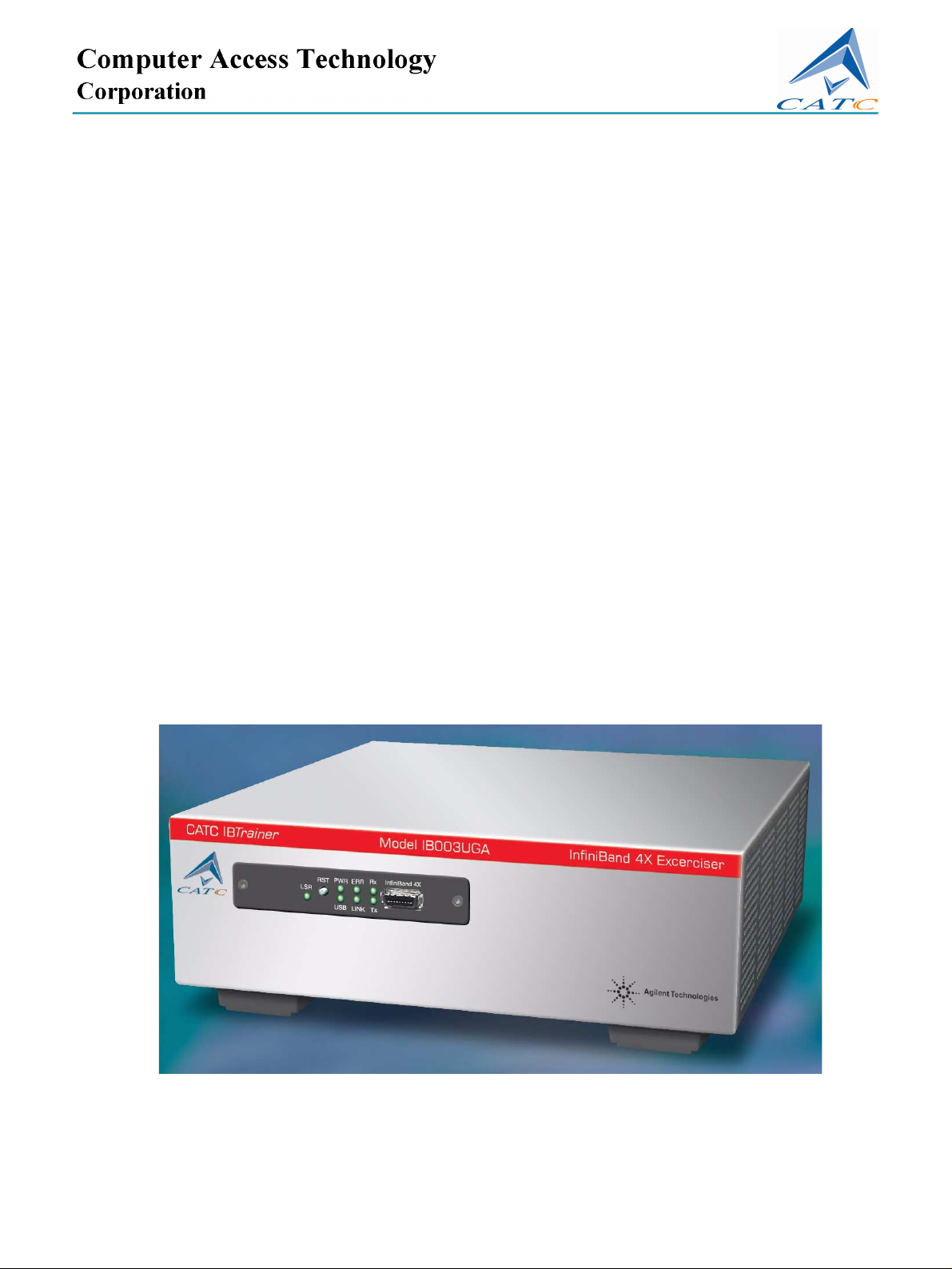
CATC IBTrainer InfiniBand Exerciser
User’s Manual
For Software Version 2.0
Manual Version1.0
16 August, 2002
Page 2

Important Notice
Manual PartNumber
730-0040-00
Revision
Revision 1.0, August 2002
Printed in U.S.A.
Computer Access Technology Corporation,
2403 Walsh
Avenue, Santa Clara CA 95951
USA
Document Disclaimer
The information in this document has been
carefully checked and is believed to be reliable.
However, no responsibility can be assumed for
inaccuracies that may not have been detected.
CATC reserves the right to revise the information
in this document without notice or penalty.
Trademarks and Servicemarks
CATC, Merlin, NetMate, Advisor, Chief,
FireInspector, Inspector, IBTracer, Detective,
Traffic Generator, BusEngine, USB4DOS, UPT,
HPT, and UHT are trademarks of Computer
Access Technology Corporation.
Microsoft, Windows, and Windows NT are
registered trademarks of Microsoft Inc.
All other trademarks are property of their
respective companies.
Portions of this documentation have been
licensed from Agilent Technologies, Inc.
Copyright
Copyright © 2002, Computer Access Technology
Corporation (CATC); All Rights Reserved.
This document may be printed and reproduced
without additional permission, but all copies
should contain this copyright notice.
Safety Notices
CAUTION
A CAUTION notice denotes a hazard. It calls
attention to an operating procedure, practice, or
the like that, if not correctly performed or adhered
to, could result in damage to the product or loss
of important data. Do not proceed beyond a
CAUTION notice until the indicated conditions
are fully understood and met.
WARNING
A WARNING notice denotes a hazard. It calls
attention to an operating procedure, practice, or
the like that, if not correctly performed or adhered
to, could result in personal injury or death. Do not
proceed beyond a WARNING notice until the
indicated conditions are fully understood and
met.
2 CATC IBTrainer InfiniBand Exerciser, August 2002
Page 3

Safety Information
The following general safety precautions must be observed during all
phases of operation of this instrument. Failure to comply with these
precautions or with specific warnings elsewhere in this manual
violates safety standards of design, manufacture, and intended use of
the instrument.
CATC assumes no liability for the customer's failure to comply with
these requirements.
Before operation, review the instrument and manual for safety
markings and instructions. You must follow these to ensure safe
operation and to maintain the instrument in safe condition.
Safety Summary This product is a Safety Class 1 instrument (provided with a protective
earth terminal). The protective features of this product may be
impaired if it is used in a manner not specified in the operation
instructions.
All Light Emitting Diodes (LEDs) used in this product are Class 1
LEDs as per IEC 60825-1.
Environmental conditions This instrument is intended for indoor use in an installation category
II, pollution degree 2 environment. It is designed to operate at a
maximum relative humidity of 95% and at altitudes of up to 2000
meters.
Refer to the specifications tables for the ac mains voltage
requirements and ambient operating temperature range.
Before applying power Verify that the product is set to match the available line voltage, the
correct fuse is installed, and all safety precautions are taken.
Ground the instrument To minimize shock hazard, the instrument chassis and cover must be
connected to an electrical protective earth ground. The instrument
must be connected to the ac power mains through a grounded power
cable, with the ground wire firmly connected to an electrical ground
(safety ground) at the power outlet. Any interruption of the protective
(grounding) conductor or disconnection of the protective earth
terminal will cause a potential shock hazard that could result in
personal injury.
Do not operate in an explosive
atmosphere
CATC IBTrainer InfiniBand Exerciser, August 2002 3
Do not operate the instrument in the presence of flammable gases or
fumes.
Page 4

Do not remove the instrument cover Operating personnel must not remove instrument covers. Component
replacement and internal adjustments must be made only by qualified
personnel.
Instruments that appear damaged or defective should be made
inoperative and secured against unintended operation until they can
be repaired by qualified service personnel.
EU Conformance Statement
This equipment complies with the EMC Directive 89/336/EEC and the
Low Voltage Directive 73/23/EEC, and their associated amendments
for Class A ISM Equipment. It has been tested and found to comply
with EN55022 and EN55011 (EN61000-4-2, EN61000-4-3, EN61000-4-4,
EN61000-4-5, EN61000-4-6, EN61000-4-11), and EN61010-1.
4 CATC IBTrainer InfiniBand Exerciser, August 2002
Page 5

Contents
About this Manual 9
Getting Started with the IBTrainer 11
Contents
Document History 9
Installing the Software 11
Setting Up the IBTrainer 12
Performing a First Test 12
How to Connect to the DUT 13
Controlling the Link State of the IBTrainer 14
Sending an SMP Packet 15
Evaluating the Returned Packet 17
Overview of the IBTrainer 19
Description of the Hardware 20
Installation and Maintenance 22
InfiniBand 23
Description of the Software 24
Testing Capabilities of the IBTrainer 26
Physical Layer 26
Link Layer 27
Flow Control 27
Addressing 28
Error Detection 29
Packet Length 29
Network Layer 30
Transport Layer 30
Testing Capabilities in Terms of Concrete Tests 31
CATC IBTrainer InfiniBand Exerciser, August 2002 5
Page 6

Contents
Testing with the User Interface 33
Testing Principles 34
Setting Up the Test 35
Configuring Outgoing Packets to Be Transmitted 36
How to Set Up Outgoing Packets 37
Advanced Attributes 39
How to Inject Errors in Outgoing Packets 40
Using the Transmit Memory for Generating Sequences of
Packets
How to Insert Packets in the Transmit Memory 42
How to Send a Single Packet Multiple Times 42
How to Control Skew Between the Four Lanes 43
Running the Test 44
How to Trigger the Transmission from an External Signal 45
Viewing the Results 46
41
Filtering Incoming Packets 47
Using Matching Patterns for Filtering Incoming Packets 48
Graphical Representation of the Pattern Matching Process 50
Example of Pattern Matching 51
Using Packet Handlers for Managing Incoming Packets 52
How to Write Your Own Handler 53
Managing Handlers 53
How to Configure Virtual Lanes for Rerouting Incoming
Packets
54
Setting Invalid Generator Properties 55
Using Auxiliary Features 57
Visualizing the Network Topology 58
Determining the Performance of InfiniBand Traffic 60
How to Launch a Performance Measurement 62
Sending TCL Commands to the IBTrainer 62
Extending the IBTrainer Software with Your Own TCL
Scripts
63
6 CATC IBTrainer InfiniBand Exerciser, August 2002
Page 7

Contents
Using the InfiniBand Compliance Test Suite 65
Overview of the Compliance Test Suite 66
Testing with the Compliance Tester User Interface 68
How to Add or Update Tests 69
How to Select Tests 70
How to Run Tests 71
How to Set Up and View the Report 72
Example of Report 73
Test Description 74
Available Tests 74
Packet with Bad DLID 75
Packet with Bad ICRC 77
Packet with GRH and VL15 78
Packet with Bad VCRC 80
Packet Receive Statemachine MARKED BAD PKT 81
Packet Receive Statemachine BAD PKT 82
Packet with Bad LVer 84
Packet with Bad PktLen 85
The SL Field Shall be Ignored by DUT When Using VL15 86
LMC Check 87
Number of VLs Supported 88
State Transitions 89
SMP Send and Receive in States "Initialize" and "Arm" 90
Ignoring Invalid Link State Settings 91
EUI-64 GUID Assigned by Manufacturer 92
Four Running Disparity Errors in a Sequence 92
Basic Directed Route SMP Response 93
Correct SMP Packet - Expect Response 94
SLID Check 94
Specifications 95
Operating Characteristics 95
Certification 96
Power Requirements 96
Glossary 97
CATC IBTrainer InfiniBand Exerciser, August 2002 7
Page 8

Contents
8 CATC IBTrainer InfiniBand Exerciser, August 2002
Page 9

Document History About this Manual
About this Manual
Aims This document provides the information necessary to program tests for
the CATC InfiniBand Exerciser for InfiniBand.
Target Audience The target audience is as follows:
• Device designers
Device users use the IBTrainer for debugging InfiniBand devices.
• Software engineers
Software engineers set up test environments for validating InfiniBand
devices.
Both groups should have a good knowledge of the InfiniBand
specification. In addition, software engineers should have good working
knowledge of the TCL (Tools Command Language) language or C++.
Document History
All revisions and updates of this document are listed below.
Date Document Revision Description
August 2002 1.0 Initial version of the documentation
CATC IBTrainer InfiniBand Exerciser, August 2002 9
Page 10

About this Manual Document History
10 CATC IBTrainer InfiniBand Exerciser, August 2002
Page 11

Installing the Software Getting Started with the IBTrainer
Getting Started with the IBTrainer
The IBTrainer is an exerciser for InfiniBand, designed as a standalone
unit.
Its primary purpose is to generate, receive, and analyze arbitrary
InfiniBand packets. It can serve as an endnode within an InfiniBand
fabric, insert errors, and monitor protocol compliance and performance
data on the InfiniBand link.
It is controlled by an external PC over a USB connection.
This chapter shows you how to install and use the IBTrainer and its
software. It also provides instructions on how to perform your first test.
Installing the Software
When you insert the delivered CD-ROM, the installation program of the
software starts automatically. If the Autorun function is disabled on your
PC, you can start the installation program by double-clicking on the
setup.exe file located at the root of the CD-ROM.
If you purchased the IBTrainer Compliance Test Suite, you should have
also received the necessary key. During installation, the installation
program prompts you to enter the key. The Compliance Test Suite
provides you with a large number of easy-to-use tests for quickly
verifying InfiniBand devices.
NOTE If you did not purchase the IBTrainer Compliance Test Suite, the
installation programs still installs the user interface of the Compliance
Test Suite with a few free tests.
CATC IBTrainer InfiniBand Exerciser, August 2002 11
Page 12

Getting Started with the IBTrainer Setting Up the IBTrainer
Setting Up the IBTrainer
Plug in the IBTrainer and use the delivered USB cable to connect it to
your PC.
NOTE The IBTrainer has a USB 1.1 port. The delivered USB cable has therefore
two different ends (one for the IBTrainer, one for the PC).
Now start the software to make sure that the IBTrainer is connected to
the PC:
♦ Press
The shortcut changes with the release installed. For example, if your
release is 2.0.1.0, then the name of the shortcut is
When the software starts, it looks for attached IBTrainers. The List of
Available Generators dialog box should contain the name of your
IBTra iner. If your IBTraine r is not listed, double-check the USB
connection. Please also keep in mind that Windows NT does not support
USB.
Start>Programs>CATC> IBTrainer(Release)>GUI
.
IBTrainer2.0.1.0>GUI
Performing a First Test
Once you have connected the IBTrainer to your PC, you can:
• Connect the DUT to the IBTrainer.
Refer to “How to Connect to the DUT” on page 13 for more
information.
.
• Set up the link state of the IBTrainer
• Set up and send an SMP packet to get the NodeInfo from the DUT.
Refer to “Sending an SMP Packet” on page 15 for more information.
• Evaluate the returned packet. Refer to “Evaluating the Returned
Packet” on page 17 for more information.
12 CATC IBTrainer InfiniBand Exerciser, August 2002
Page 13

Performing a First Test Getting Started with the IBTrainer
How to Connect to the DUT
After you have:
• Connected the IBTrainer to your PC
• Started the software
• Turned on the DUT
you can establish the connection between the IBTra iner and the DUT:
1 Connect the DUT to the IBTrainer with the InfiniBand cable. The
InfiniBand port is located on the front of the IBTrainer.
The List of Available Generators dialog box should be opened.
2 Connect the IBTrainer to the DUT by clicking Connect.
The Link State dialog box opens. “Controlling the Link State of the
IBTrainer” on page 14 describes this dialog box in detail.
3 Click the button corresponding to the link state that you want to
reach.
CATC IBTrainer InfiniBand Exerciser, August 2002 13
Page 14

Getting Started with the IBTrainer Performing a First Test
Controlling the Link State of the IBTrainer
The status bar shows you the current link state of the IBTrainer.
If the link state does not correspond to the desired transmission packet,
you can set the link state by selecting Generator>Link State. The Link
State dialog box opens.
This dialog box consists of two groups, reflecting the conventions given
in the InfiniBand specification:
• Link Training State Machine, corresponding to the Physical layer
Link initialization, configuration, and link error recovery operations
are performed by the link training state machine. The primary states
for the link training state machine that you can set in the Link State
dialog box are Disabled, Sleep or Poll.
• Link State Machine, corresponding to the Link layer
As described in the InfiniBand specification, the link layer handles the
sending and receiving of data across the links at the packet level. The
specification uses state machines to define the logical operation of the
link layer. The different stages of the link state machine that you can
set in the Link State dialog box are Down, Arm or Active.
The InfiniBand specification requires that the current link states of two
InfiniBand devices connected together must be identical before the link
state of one of the devices can be set a level higher. Here, you can
activate AutoNegotiate to let the IBTrai ner handle the intermediate
steps for reaching the desired link state for both the IBTrainer and the
DUT, provided that no Subnet Manager is attached to the network.
14 CATC IBTrainer InfiniBand Exerciser, August 2002
Page 15

Performing a First Test Getting Started with the IBTrainer
For instance, if both devices are set to Initialized, you can select
AutoNegotiate and click Active to have both devices set as Active: the
IBTrainer sets the link state from Initialized to Armed and then from
Armed to Active for both devices.
Because we intend to only send Subnet Management packets (SMP) in
the current test, we only need to set the link training of the IBTrainer to
Poll. In that case, the status of the link training state machine eventually
becomes LinkUp and the link state machine Initialized.
Sending an SMP Packet
The software is delivered with three sample packets that you can use for
your first tests:
• Sample SMP packet which is a Subnet Management Packet
• Sample IB packet which is a standard InfiniBand packet
• Sample GMP packet which is a Management datagram (MAD) packet
CATC IBTrainer InfiniBand Exerciser, August 2002 15
Page 16

Getting Started with the IBTrainer Performing a First Test
For our first test, we use the Sample SMP packet. To set up and send this
packet:
1 Check that this packet is set up so that the IBTrainer queries the
NodeInfo property of the DUT by double-clicking Sample SMP packet.
The SMP Packet: Sample SMP Packet dialog box opens.
This dialog box shows the properties of the selected packet. Following
default values should be set:
– Method is set to 0x01 - Get.
– Attribute ID is set to 0x11 - NodeInfo.
If not set, change these values to the ones above, and click Ok to
accept changes and close the window.
2 Right-click on Sample SMP, and select Transmit to send the packet.
16 CATC IBTrainer InfiniBand Exerciser, August 2002
Page 17
Performing a First Test Getting Started with the IBTrainer
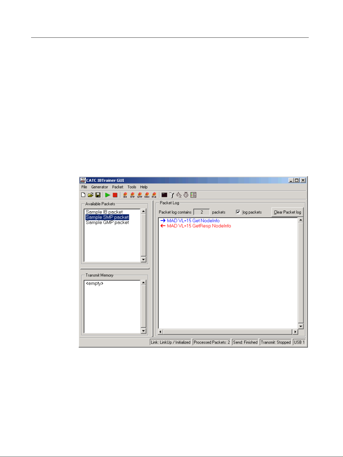
Evaluating the Returned Packet
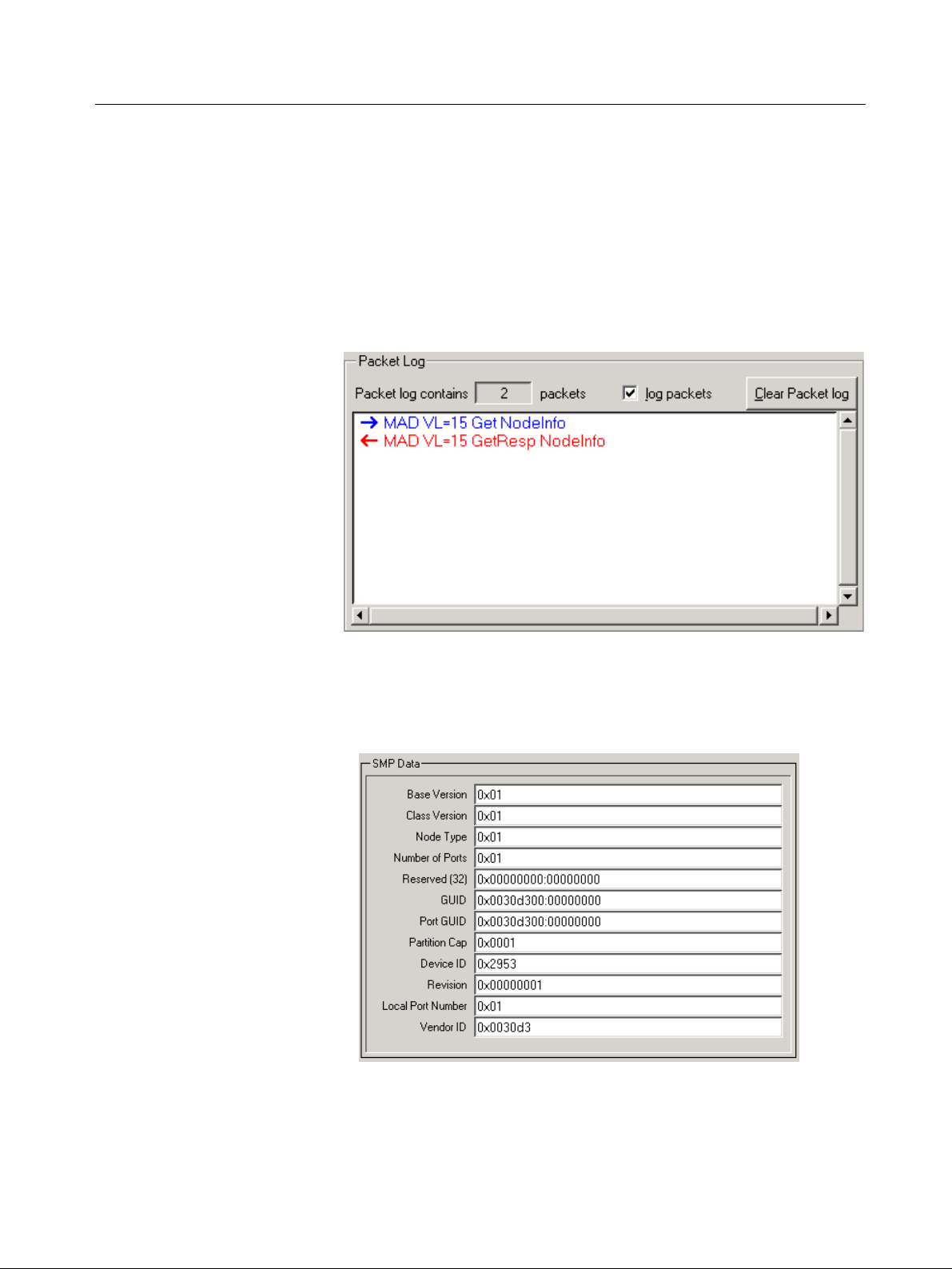
After you have sent the SMP packet, an entry appears in blue in the
Packet Log window. The IBTrainer then listens for a response from the
DUT.
When the DUT answers, a new entry corresponding to the returned
packet appears in red in the Packet Log window, as shown in the figure
below.
Double-click the returned packet’s entry. The SMP packet: MAD VL=15
getResp NodeInfo dialog box opens. The NodeInfo properties are then
displayed in the SMP Data list in this dialog box, as shown in the
following figure.
You can compare the received NodeInfo properties with the DUT’s
values to ensure that the packet was correctly transmitted.
CATC IBTrainer InfiniBand Exerciser, August 2002 17
Page 18

Getting Started with the IBTrainer Performing a First Test
18 CATC IBTrainer InfiniBand Exerciser, August 2002
Page 19
Overview of the IBTrainer
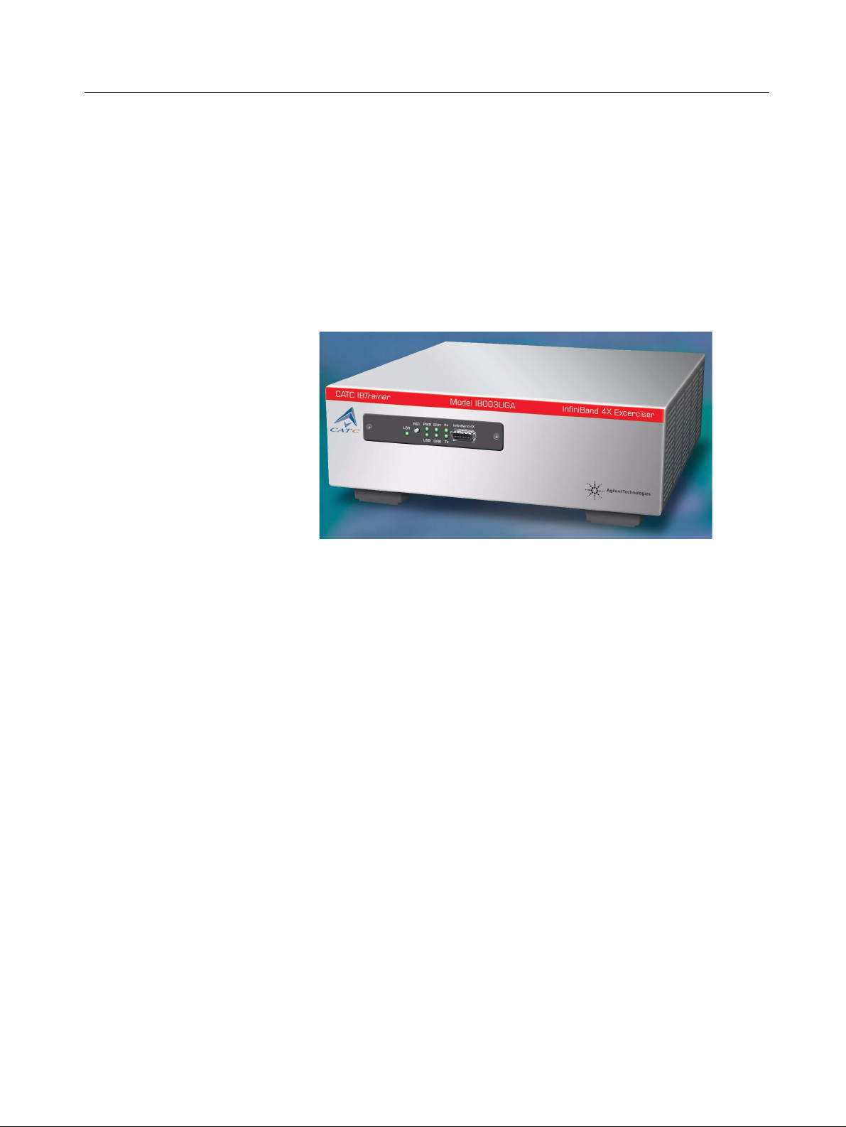
The IBTrainer is a 4x Exerciser for InfiniBand, designed as standalone
units. It is controlled by an external PC using the USB connection and
can be programmed to generate arbitrary InfiniBand packets behaving as
endpoint or endnode within an InfiniBand network.
Overview of the IBTrainer
In the following, IBTrainer stands for both generators. This chapter
describes:
• “Description of the Hardware” on page 20
• “InfiniBand” on page 23
• “Description of the Software” on page 24
• “Testing Capabilities of the IBTrainer” on page 26
CATC IBTrainer InfiniBand Exerciser, August 2002 19
Page 20
Overview of the IBTrainer Description of the Hardware
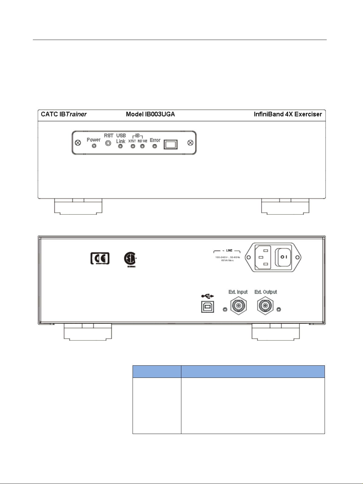
Description of the Hardware
The front panel of the IBTrainer is as follows:
The rear panel of the IBTrainer is as follows:
LEDs The front panel of the IBTrainer contains the following LEDs:
LED Lights when...
Power indicator Main power is switched on.
USB Link USB link to the control PC has been established.
IB XMIT Xmit LED is lit when InfiniBand link is up; flashes
when packets are transmitted.
IB RCVE Packets are being received.
Red Error An error has occurred.
20 CATC IBTrainer InfiniBand Exerciser, August 2002
Page 21

Description of the Hardware Overview of the IBTrainer
Its front panel contains the following LEDs:
LED Lights when...
Pwr Main power is switched on.
Usb USB link to the control PC has been established.
Link Lights when InfiniBand link is up.
Tx Blinks when packets are transmitted.
Rx Blinks when packets are being received.
Err An error has occurred.
Push-button and Connector Additional elements on the front panel are:
• RST push-button to reset the InfiniBand link or run built-in self-test
(press the RST button for about 5 s).
• InfiniBand connector
NOTE Here is what happens when you press the RST push-button for about 5
seconds to run the built-in self-test:
• You hear four short beeps.
• all LEDs light and then turn off.
• RX, TX and Link LEDs light
If the test passes, two short high-pitch beeps sound, and eventually the
power LED comes on, all other LEDs are off (normal power-up state).
if the test fails, error LED comes on, three longer low-pitch beeps sound,
and RX, TX and link show specific pattern. You need to contact your
CATC representative.
Rear Panel Connectors The rear panel has various connectors:
• Wide-range AC connector module
Power socket with power on/off switch
• USB port
• External input (for triggering) with following cable specifications:
LVTTL level, low active, internal termination: 50 ohm to +2.5V, level
sensitive
The associated LED indicates trigger activity.
• External output (for triggering) with following cable specifications:
LVTTL level, low active
The associated LED indicates trigger activity.
CATC IBTrainer InfiniBand Exerciser, August 2002 21
Page 22

Overview of the IBTrainer Description of the Hardware
WARNING • Do not open the unit. There are no operator serviceable parts inside.
For servicing contact your CATC representative.
• To prevent the influence of ESD on measurements, all tests must be
performed in an ESD-protected environment.
Installation and Maintenance
Initial Inspection Inspect the shipping container for damage. If the container or cushioning
material is damaged, keep it until the contents of the shipment have been
checked for completeness and the instrument has been verified both
mechanically and electrically.
WARNING To avoid hazardous electric shock, do not perform electrical tests when
there are signs of shipping damage to any part of the instrument's outer
covers or panels.
If the contents are incomplete, or there is mechanical damage, or if the
instrument does not work as expected within its specifications, notify
the nearest CATC office.
Power Requirements The instrument can operate from any single-phase AC power source
supplying 100 – 240 V in the frequency range from 50 – 60 Hz. The
maximum power consumption is 100 VA with all options installed. When
the instrument is switched on the power supply adapts automatically to
the applied AC power (Auto Selection) and monitors the AC power range
during operation.
Ventilation Requirements Make sure that there is adequate clearance of 30 mm at the left and the
right side to ensure adequate air flow. If the air flow is restricted, the
internal operating temperature will be higher, reducing the instrument's
reliability.
NOTE Do not cover the ventilation holes.
Cleaning Recommendation Use a dry cloth or one slightly dampened with water to clean external
case parts. Do not attempt to clean internally.
WARNING To prevent electrical shock, disconnect the instrument from mains
before cleaning.
22 CATC IBTrainer InfiniBand Exerciser, August 2002
Page 23

InfiniBand Overview of the IBTrainer
InfiniBand
InfiniBand architecture The InfiniBand Architecture (IBA) is designed around a point-to-point,
switched I/O fabric, whereby end node devices (which can range from
very inexpensive I/O devices like single chip SCSI or ethernet adapters to
very complex host computers) are interconnected by cascaded switch
devices. The physical properties of the IBA interconnect support two
predominant environments, with bandwidth, distance and cost
optimizations appropriate for these environments:
• Module-to-module, as typified by computer systems that support I/O
module add-in slots
• Chassis-to-chassis, as typified by interconnecting computers, external
storage systems, and external LAN/WAN access devices (such as
switches, hubs, and routers) in a data-center environment.
InfiniBand specification The design and implementation of the IBTrainer and its test capabilities
is based on the InfiniBand Specification InfiniBand
Specification Volume 1 and 2 Release 1.0.a from June 19, 2001.
The IBTrainer 4x (by four) Exerciser for InfiniBand uses the electrical
4x connection as set down in the InfiniBand Specification.
• The signalling rate for encoded data on the media is 2.5 Gbits/sec,
which results in a data rate that can be considered to be 250
MBytes/second. The connections are point to point and full duplex,
unidirectional.
• The byte stream on each physical lane is encoded using the industry
standard 8B/10B coding.
• The following interface width is available for the IBTrainer:
8 differential pairs, 4 per direction for a total of 16 wires
TM
Architecture
CATC IBTrainer InfiniBand Exerciser, August 2002 23
Page 24
Overview of the IBTrainer Description of the Software
Description of the Software
The IBTrainer can only be controlled by a PC. This can be done by
programming TCL scripts or C++ programs using the API or by using the
Graphical User Interface (GUI).
Graphical User Interface The Graphical User Interface provides an easy way of:
• Performing simple tests on InfiniBand devices.
• Determining and displaying the traffic performance as a diagram.
• Visualizing the topology of the InfiniBand network containing the
IBTrainer as end-node.
API For more extensive testing, such as the validation of an InfiniBand
device, programs written in TCL or C++ can be used to control the
IBTra iner.
NOTE The TCL interpreter is installed with the software.
24 CATC IBTrainer InfiniBand Exerciser, August 2002
Page 25

Description of the Software Overview of the IBTrainer
Optional software module The IBTrainer comes with an optional InfiniBand Compliance test
module. This module can be called directly from the GUI. It consists of a
series of prewritten InfiniBand compliance tests that you can run to
automatically verify a large number of compliance statements defined in
the InfiniBand specification, providing a pass/fail result.
Requirements The IBTrainer works with any personal computer using:
• Windows 98SE ®
• Windows 2000 ®
• Windows XP ®
• Windows NT ® only in demo/offline mode
• Windows ME ® operating systems
The software can also be used offline for demonstration or test
development purposes.
Licensing No license is necessary to run the Graphical User Interface.
For the Compliance Test software, the standard shipment includes eight
free tests. To install additional tests, you have to purchase the IBTrainer
Compliance Test Suite option. You will receive a license key that you
have to enter during installation.
CATC IBTrainer InfiniBand Exerciser, August 2002 25
Page 26

Overview of the IBTrainer Testing Capabilities of the IBTrainer
Testing Capabilities of the IBTrainer
This section lists the key test capabilities of the IBTrain er. They are
structured along the following ISO/OSI layers as described in the
InfiniBand specification:
• Physical layer
• Link layer
• Network layer
• Transport layer
“Testing Capabilities in Terms of Concrete Tests” on page 31 gives a list
of the capabilities of the IBTrainer as defined by the Compliance
Interoperability Work Group (CIWG).
Physical Layer
The IBTrainer is not capable of testing the physical layer.
As described in the IB specification, the physical layer is the physical
connection between two devices. Thus, there are certain aspects of
InfiniBand connections that the IBTra iner does not test:
• Signal level, quality, and frequency
• 8B/10B encoding and decoding
The IBTrainer makes comma and skip insertions according to the
InfiniBand specification (1 comma and 3 skip symbols occur every 4352
to 4608 clocks). The number of skips cannot be influenced. The
IBTra iner generates idle packets as described in the InfiniBand
specification.
You can, however, insert running disparity errors into the data stream.
Running disparity errors can be created only within packets. This is
controlled by the packet behavior setting. Such packet behavior is
controlled by the packet property setting.
26 CATC IBTrainer InfiniBand Exerciser, August 2002
Page 27

Testing Capabilities of the IBTrainer Overview of the IBTrainer
Link Layer
Definition As described in the InfiniBand specification, services provided by the
link layer include:
•Flow control
Refer to
• Addressing
Refer to
• Error detection
Refer to
•Switching
Switching is not a capability of the IBTr ainer.
The IBTrainer automatically sets up the link. Its hardware sends and
receives training sequences and link packets. The link status (link up /
link down / no signal) can be read out of the status registers.
“Flow Control” on page 27 for more information.
“Addressing” on page 28 for more information.
“Error Detection” on page 29 for more information.
NOTE A behavior is a property setting that applies to a single packet.
Virtual Lanes The IBTrainer supports all the possible virtual lanes, including VL 15,
which is used for management purposes. The particular virtual lanes that
are to be supported are user-selectable using a resource and enabling
mechanism.
Flow Control
Flow control packets are generated automatically by the IBTrainer. The
packets also pass credits back and forth within the InfiniBand network.
You can influence the credit system of the IBTrainer in several ways.
Receive Credits Credits are given per virtual lane. Each virtual lane can be configured to
behave in two different ways:
• Credits can be given out automatically, which turns the IBTrainer into
an unlimited data sink. Maximum credit is given out for any virtual
lane set to this mode. This mode is called the data sink mode.
• Credits are given out until such time that the data receive memory is
full. It is then up to the software to process each packet, and you can
instruct the software to give out credits as soon as the receive memory
is read out (until such time that the memory is full again). This mode is
called the packet control mode.
CATC IBTrainer InfiniBand Exerciser, August 2002 27
Page 28

Overview of the IBTrainer Testing Capabilities of the IBTrainer
The receive memory of the IBTrainer consists of a single block of 2
Mbytes. By selecting a virtual lane resource you decide which path the
data stream is to use. Refer to “Receiving Packets” on page 31 for more
information.
Transmit Credits You can set a behavior for each packet to either ignore credits or to
behave according to the specification.
Detailed organization of the IBTrainer credit system is as follows:
• The FCCL calculation is based on a 12-bit Adjusted Blocks Received
(ABR) counter maintained for each virtual lane at the receiver. The
ABR counter is set to zero when the link initializes. This is in
accordance with the specification. Upon receipt of each flow control
packet, the ABR sets the value of the FCTBS (Flow Control Total
Blocks Sent) field.
• Upon receipt of each data packet, the ABR is incremented by the
number of blocks received, modulo 4096. The ABR does not get
incremented due to received packets that have been discarded due to
the lack of receive capacity in the receiver. You can adjust this
capacity for the IBTrainer in the data sink mode.
• Upon transmission of a flow control packet, the FCCL is set to one of
the following:
– If the current buffer state of the receiver permits reception of 2048
or more blocks from all combinations of valid InfiniBand packets
without discarding them, the FCCL is set to ABR plus 2048 modulo
4096.
– Otherwise the FCCL is set to ABR plus the number of blocks the
receiver is capable of receiving from all combinations of valid
InfiniBand packets without discarding these, modulo 4096.
Addressing
Source addresses are generated automatically depending on the address
supplied to the IBTrainer by the subnet manager. Source addresses can
be overwritten. This way the IBTraine r can emulate a switch or a router.
The IBTrainer is capable of generating all types of InfiniBand packets as
allowed by the specification. This includes any MAD packets, any regular
InfiniBand packets, Raw or RawIPv6 packets. Refer to section 5.2 in the
InfiniBand specification (data packet format) for more details.
The destination address for the packets is always defined by the user.
28 CATC IBTrainer InfiniBand Exerciser, August 2002
Page 29

Testing Capabilities of the IBTrainer Overview of the IBTrainer
Error Detection
The IBTrainer calculates the ICRC (Invariant CRC) and the VCRC
(Variant CRC) automatically. You can influence this by making one of the
following choices:
• Τhe behavior ‘bad packet’ causes the IBTrainer to end the packet with
a bad packet delimiter (EBP).
• The behavior ‘bad ICRC’ corrupts the ICRC.
• The behavior ‘bad VCRC’ corrupts the VCRC.
To corrupt a packet, the IBTrainer places the 1’s complement of the
appropriate CRC calculated for the transmitted packet in the CRC field.
Packet Length
The IBTrainer distinguishes between the real packet length and the
shown packet length. The real packet length is purely an internally used
value, which can, but does not have to, correlate with the packet length
shown in the packet header. You can create an illegal packet length by
setting the shown length to a value that is at variance with the real packet
length. You can set this behavior on a per-packet basis.
CATC IBTrainer InfiniBand Exerciser, August 2002 29
Page 30

Overview of the IBTrainer Testing Capabilities of the IBTrainer
Network Layer
The network and link protocols deliver a packet to the desired
destination. The transport portion of the packet delivers the packet to
the proper Queue Pair and instructs the Queue Pair how to process the
packet’s data.
The receiver part of the IBTrainer can be programmed to either discard
or keep invalid packets that arrive at the generator (wrong IP version
field, wrong DGID and so on).
Transport Layer
The IBTrainer lets you set up or program all elements of the transport
layer. With the user interface delivered with the IBTrainer or self-written
TCL scripts or C++ applications you can control the IBTrainer to
generate all types of InfiniBand traffic.
Transmitting Packets The programming of the IBTra iner is packet based (not message based).
You have two basic choices of generating packets with the IBTrainer:
• Direct packet FIFO
This FIFO can be used to generate arbitrary packets directly out of
software. The direct software call
packet)
packet buffer and sends it out immediately. This method of sending
packets has priority over the transmit memory-based packet
generation. Its purpose is to generate MAD (Management Datagram)
packets (for subnet management) or any other high priority packets
whenever this is required, without having to wait for the transmit
memory to finish sending packets and get reprogrammed with the
next sequence.
• Memory-based packet generation
You can fill a block memory with up to 1024 InfiniBand packets which
are then executed in a row. There are additional properties that you
can set, such as the inter-packet delay. All behaviors are listed under
“Using the Transmit Memory for Generating Sequences of Packets”
on page 41. The transmit memory can be looped and offers a feature
to repeatedly send single packets from the programmed packet
sequence. Additionally the transmit memory can increase the packet
sequence number automatically to generate continuous streams of
packets (and can include very large data payloads).
; from the
IGCGenerator
void PacketSend (IGCPacket &
class passes a packet down to this
30 CATC IBTrainer InfiniBand Exerciser, August 2002
Page 31

Testing Capabilities of the IBTrainer Overview of the IBTrainer
Receiving Packets The IBTrainer is capable of responding to incoming packets under
software control. The receive memory amounts to 2 MBytes for the
IBTrainer.
To filter incoming packets, you can apply a pattern matcher on the
incoming packets. These can be passed either into the receive buffer or
into the memory block of the receive memory or simply discarded. Each
pattern matcher can, if active, fire a certain action in addition to selecting
the path for each received packet. Refer to “Using Matching Patterns for
Filtering Incoming Packets” on page 48 for more information.
By setting a behavior for each virtual lane you can determine whether the
incoming packets should be stored in the receive memory or discarded
(see “How to Configure Virtual Lanes for Rerouting Incoming Packets”
on page 54). All packets stored in the receive memory must be handled
by the user application.
Testing Capabilities in Terms of Concrete Tests
Code Group Test The Code Group test requires the following capabilities:
• Send/receive code groups
• Test the Physical Layer and parts of the Link Layer
Using the settings for the packet send command, you can utilize the
IBTrainer to introduce illegal code groups or bursts of illegal code
groups into the packet data stream.
Packet Test The Packet test requires the following capabilities:
• Send / receive link and data packets
• Test the Link and Network Layer
The IBTrainer is ideally suited for this type of test. Its programming
interface is designed for this type of test.
MAD Test The MAD test requires the following capabilities:
• A more abstract packet test
• Send / receive MADs
The IBTrainer is capable of this type of test.
CATC IBTrainer InfiniBand Exerciser, August 2002 31
Page 32

Overview of the IBTrainer Testing Capabilities of the IBTrainer
Transpo rt Test The Transport test requires the following capabilities:
• A full Verbs-like interface
This type of test is not ideally covered by the IBTrainer. A standard Host
Channel Adapter (HCA) is likely to be better suited than the IBTrainer .
32 CATC IBTrainer InfiniBand Exerciser, August 2002
Page 33

Testing with the User Interface
Testing with the User Interface
This section gives information about the test architecture and shows
how to set up and run the desired test.
• Testing Principles
Overview of the process used to perform a test
• Setting Up the Test
Instructions for setting up the packets to be sent to the DUT
• Running the Test
Information on the test execution
• Viewing the Results
Interpretation of the results
CATC IBTrainer InfiniBand Exerciser, August 2002 33
Page 34

Testing with the User Interface Testing Principles
Testing Principles
Sending packets With the IBTrainer, you send InfiniBand packets to the DUT and analyze
the answer of the DUT. These packets can be valid InfiniBand packets or
can also contain errors injected manually.
This section shows the major steps necessary for setting up and
performing a test on a DUT with the IBTrainer and its software. Testing
with the Graphical User Interface means:
1. Connecting to the DUT
Refer to “How to Connect to the DUT” on page 13 for more
information.
2. Setting up the test
You can set up the InfiniBand properties of the packet to be sent. In
addition, the software lets you also set additional attributes like
inserting bad CRC values in the packet, or enabling to inject errors to
the packet. Refer to “Configuring Outgoing Packets to Be
Transmitted” on page 36 for more information.
The software lets you also use the transmit memory of the IBTrainer
to send generate several packets at the same time. Refer to “Using the
Transmit Memory for Generating Sequences of Packets” on page 41
for more information.
You can also insert a delay between the four lanes and verify that your
DUT reacts as expected by the InfiniBand specification. Refer to
“How to Control Skew Between the Four Lanes” on page 43 to find
out how.
3. Running the test
After you have set up the packets to be sent, you can send them to the
DUT. “Running the Test” on page 44 tells you how.
4. Interpreting the results
After packets have been sent to the DUT, the DUT may answer or not
depending on the packet sent. “Viewing the Results” on page 46 tells
you how.
Setting invalid generator properties Another possibility for testing a DUT is to set up invalid properties for
the current IBTrainer generator. Each DUT connected to the generator
asking for the generator’s properties becomes a packet with invalid
generator’s properties. You can then check whether the DUT behaves as
expected. Refer to “Setting Invalid Generator Properties” on page 55
for more information.
34 CATC IBTrainer InfiniBand Exerciser, August 2002
Page 35

Setting Up the Test Testing with the User Interface
Setting Up the Test
Using pre-defined packets The software is delivered with three sample packets that you can use for
your tests:
• Sample SMP packet, which is a Subnet Management Packet
This packet is set up so that the IBTrainer queries the NodeInfo
property of the DUT.
• Sample GMP packet, which is a General Management Packet.
Each node may contain additional management agents (besides the
Subnet Management Agent which is transmitted with the SMPs)
referred to as General Services Agent (GSA).
As specified in the InfiniBand specification, SMP packets are used for
managing communication between nodes, GMP packets (General
Management Packets) are needed for the communication with the
GSA. You can verify the GSA of a node using GMPs just like you verify
the SMA using the SMPs.
This GMP sample packet is set up to query the performance
management of the DUT for PortSamplesControl.
• Sample IB packet, which is a standard InfiniBand packet
This packet is set up with the opcode RC SEND only.
You can send one of these three packets directly to the DUT or you can
customize them before sending. “Configuring Outgoing Packets to Be
Transmitted” on page 36 tells you how.
Creating packets from scratch You can also create a packet from scratch. Click the button on the
toolbar corresponding to the type of packet that you want to create: The
software prompts you to name the packet and places the packet in the
Available Packet list.
CATC IBTrainer InfiniBand Exerciser, August 2002 35
Page 36

Testing with the User Interface Setting Up the Test
In addition to IBA, SMP and GMP packets, you can create packets of the
following types:
•RAW packet
RAW packets may be routed on InfiniBand fabrics but do not contain
InfiniBand transport headers. From the InfiniBand point of view, these
packets contain only InfiniBand routing headers, payload and CRC.
• IPv6 packet
IPv6 packets are RAW packets containing IPv6 transport headers.
You can customize a newly created packet before sending it.
“Configuring Outgoing Packets to Be Transmitted” on page 36 tells you
how.
NOTE Before sending a packet to the DUT, make sure that the necessary link
state of the IBTrainer has been set up. Refer to “Controlling the Link
State of the IBTrainer” on page 14 for more information.
Configuring Outgoing Packets to Be Transmitted
After you have created a new packet or selected a pre-defined one, you
can:
• Change the properties of the packet, as described in the InfiniBand
specification.
InfiniBand packet properties are described in detail in the Properties
and Programmatic Settings section of the API Reference.
• Set advanced attributes.
In addition to pure InfiniBand packet properties, the software sends
commands in form of attributes to the DUT. These attributes are
aimed at testing the DUT and are described in detail in “Advanced
Attributes” on page 39.
36 CATC IBTrainer InfiniBand Exerciser, August 2002
Page 37

Setting Up the Test Testing with the User Interface
How to Set Up Outgoing Packets
To change the properties of a given packet:
1 Select the packet.
The packet can be located either in the Available Packets list if you
want to send it directly to the DUT or in the Transmit Memory list if
you want to use the transmit memory. Refer to “Using the Transmit
Memory for Generating Sequences of Packets” on page 41 to get more
information about the transmit memory.
2 Double-click the packet.
The dialog box that opens lists the properties of the selected packet.
You can change InfiniBand properties directly or/and set advanced
attributes by clicking Advanced attributes.
NOTE Packet properties change with the type of packet selected (SMP, IBA,
GMP, RAW or IPv6).
3 For the RAW, IPv6 and IBA packets, you can type in the payload of the
packet directly or load an existing file containing the payload of the
packet by clicking Load Payload from File.
The following figure shows an example of an IBA packet for which the
payload has been specified directly.
CATC IBTrainer InfiniBand Exerciser, August 2002 37
Page 38

Testing with the User Interface Setting Up the Test
38 CATC IBTrainer InfiniBand Exerciser, August 2002
Page 39

Setting Up the Test Testing with the User Interface
Advanced Attributes
Advanced attributes are sent with the packet and allow you to perform
various testing operations. Special attributes are given in the following
table.
Attribute Range Default Description
Repeat 0 - 3 0 (only considered for packets sent through the transmit memory)
Defines the repeat counter to be taken for this packet. A value
of 0 means a fix repeat value of 1. All other values must be set
as generator properties.
“How to Send a Single Packet Multiple Times” on page 42 describes this method in detail.
UsePRBS 0 - 1 0 Uses PRBS instead of programmed payload.
PRBS payload length 0 - 4096 0 PRBS Payload length in Bytes.
Wait Trigger In 0 - 1 0 Waits for trigger in.
“How to Trigger the Transmission from an External Signal” on
page 45 describes this method in detail.
Assert Trigger Out 0 – 1 0 Asserts trigger out (at beginning of packet before inter packet
delay starts).
WaitStep 0 - 1 0 (only considered for packets sent through the transmit memory)
Waits for a Tr ans mi tS te p event. Puts a packet on hold until the
user issues a TransmitStep call or a pattern term asserts this
signal, which allows waiting for software controlled
acknowledges or specific external events (via pattern term).
InterPacket Delay Offset 0 - 3 0 (only considered for packets sent through the transmit memory)
Inter Packet Delay Exponent 0 - 7 0
Insert Error 0 – 6 0 = no
error
Bad ICRC 0 – 1 Creates bad ICRC.
Bad VCRC 0 – 1 Creates bad VCRC.
IgnoreCredit 0 – 1 Ignores Credit status (send anyway).
Auto-Calculate PSN 0 - 1 0 Calculates the PSN automatically starting with a generic start
NOTE When set to a value different from the default one, the attributes Repeat
and Insert Error require that you subsequently change the generator’s
settings. “How to Send a Single Packet Multiple Times” on page 42 and
“How to Inject Errors in Outgoing Packets” on page 40 show you how.
Inter Packet Delay (before this packet). The real value “d” for
the delay is calculated using the following formula:
d = offset + 8
Code for the error to be inserted at the end of the packet. For a
detailed list of error codes, see error list, see “How to Inject Er-
rors in Outgoing Packets” on page 40.
value out of a register.
exponent
- 1
CATC IBTrainer InfiniBand Exerciser, August 2002 39
Page 40

Testing with the User Interface Setting Up the Test
How to Inject Errors in Outgoing Packets
You can insert an error in an outgoing packet. Possible errors are listed
in the following table:
Error Description
EBP Ends a packet with the ‘end of bad packet’ symbol.
SLP Ends a packet with the ‘start of link packet’ symbol.
SDP Ends a packet with the ‘start of data packet
symbol.
InvalidCodeGroup Each correct packet ends with an End of Good
Packet (EGP) symbol. InvalidCodeGroup sends out
an invalid code group instead of EGP. This code
group is specified in the generator’s settings.
RunningDisparityError Inserts a running disparity error.
RunningDisparityError
Burst
Reserved Not used.
Inserts 4 running disparity errors spread out over
16 symbols.
Note: This method corresponds to check whether
the InfiniBand link automatically reinitializes.
Follow these steps to inject errors in outgoing packets:
1 Double-click the packet of interest in either the Available Packets list
or the Transmit Memory list.
The dialog box containing the properties of the packet of interest
opens.
2 Click Show Advanced attributes.
3 Select the error method of interest in the Insert Error list and click
Ok.
4 If you selected the InvalidCodeGroup method, you have to set the
invalid error code to be sent in the generator’s settings:
– Click Generator>Settings.
40 CATC IBTrainer InfiniBand Exerciser, August 2002
Page 41

Setting Up the Test Testing with the User Interface
– Set the invalid code group in the Code Group box.
The invalid code group value is a 10B-Code.
–Click Ok.
Using the Transmit Memory for Generating Sequences of Packets
You can fill a block memory with InfiniBand packets that are then sent
consecutively. The IBTrainer has 2 Mbytes of transmit memory.
There are additional properties that you can set for packets stored in the
transmit memory:
• You can, for instance, set the delay between packets stored in the
transmit memory. This method is described in detail in “Advanced
Attributes” on page 39.
• The transmit memory offers a feature to repeatedly send single
packets from the programmed packet sequence. Refer to “How to
Send a Single Packet Multiple Times” on page 42 for more
information.
• If you have set up a lot of packets in the transit memory that should be
sent as a response to either a received packet or a software-controlled
event, you can specify in the packet properties that a certain packet
should wait for a step signal. This special attribute, called WaitStep, is
set as an advanced attribute in the packets’s properties. Refer to “How
to Set Up Outgoing Packets” on page 37 for more information.
CATC IBTrainer InfiniBand Exerciser, August 2002 41
Page 42

Testing with the User Interface Setting Up the Test
• Similarly, you can specify the properties of a packet in the transit
memory that should be sent upon an external trigger signal. Refer to
“How to Trigger the Transmission from an External Signal” on
page 45 for more information.
How to Insert Packets in the Transmit Memory
To insert a new packet in the transmit memory:
1 Create a new packet.
– or –
Select a pre-defined packet.
2 Drag and drop the selected packet to the Transmit Memory list.
3 You can set up the properties of the packets stored in the transmit
memory before sending them. Refer to “Configuring Outgoing
Packets to Be Transmitted” on page 36 for more information.
How to Send a Single Packet Multiple Times
The transmit memory offers a feature to repeatedly send specific
packets.
You can set the number of times the packet is sent by using a counter.
Three counters are available in the software and must be set in the
generator’s settings.
To set up a packet so that the IBTrainer sends it multiple times:
1 Select the counter that the packet should use.
– Double-click the packet of interest in the Transmit Memory list.
The dialog box containing the properties of the packet of interest
opens.
– Click Show Advanced attributes.
42 CATC IBTrainer InfiniBand Exerciser, August 2002
Page 43

Setting Up the Test Testing with the User Interface
– Enter the counter’s number that you want to use between 0x1
(counter number 1), 0x2 (counter number 2) and 0x3 (counter
number 3).
–Click Ok.
2 Define how often the packet should be sent.
–Click Generator>Settings.
–The Generator Settings dialog box opens.
– Enter the number of times the packet is sent in the box
corresponding to the counter you selected.
–Click Ok.
How to Control Skew Between the Four Lanes
From the InfiniBand specification, an InfiniBand device is expected to
accept a given lane skew. You can artificially insert a delay between the
four lanes to verify that your DUT fulfills this InfiniBand requirement.
To insert a delay between lanes:
1 Select Generator>Lane Skew.
The Lane Skew Settings and Status dialog box opens.
2 In the Transmit Lane Skew list, set the delay (in symbol times)
between the lanes for each lane by means of the adequate lists.
3 Click Apply.
The DUT should then notice the lane skew and reacts as expected.
CATC IBTrainer InfiniBand Exerciser, August 2002 43
Page 44

Testing with the User Interface Running the Test
NOTE The Receive Lane Skew list displays the lane skew of the received
InfiniBand traffic.
Running the Test
After you have set up the packet(s) of interest, you can send them to the
DUT.
If you have set up a single packet, you just need to right-click it and
select Transmit from the context menu.
If you have placed packets in the transmit memory, click the Run button
on the toolbar to send them to the DUT.
Using an external trigger In addition, you can specify in the properties of a given packet stored in
the transmit memory that the IBTrainer waits for an external trigger
signal before sending it and the following packets. Refer to “How to
Trigger the Transmission from an External Signal” on page 45 for
more information.
44 CATC IBTrainer InfiniBand Exerciser, August 2002
Page 45

Running the Test Testing with the User Interface
How to Trigger the Transmission from an External Signal
With the software, you can specify in the properties of a given packet
stored in the transmit memory that the IBTrai ner waits for an external
trigger signal before sending it and the following packets.
1 Connect the instrument generating the trigger signal to the IBTr ainer
via the Ext. Input connector located on the rear of the IBTrainer. The
cable should have following characteristics: LVTTL level, low active,
internal termination: 50 ohm to +2.5V, level sensitive.
The associated LED indicates trigger activity.
2 In the software, create a new packet.
– or –
Use a pre-defined packet.
3 Drag and drop this packet to the Transmit Memory list.
4 Double-click the packet.
The dialog box displaying the properties of the packet opens.
5 Click Advanced attributes.
6 Enter 1 (True) in the Wait Trigger In box.
7 Click Ok.
8 On the toolbar, click the Run button.
The IBTrainer waits for the trigger signal to send the set packet and
all following packets to the DUT.
NOTE You can also use the IBTrainer to trigger another test device when a
specific packet is sent. Connect your cable (characteristics: LVTTL level,
low active) to the Ext. Output connector. In the dialog box displaying the
packet’s properties, click Show advanced attributes and set Assert
Trigger Out to 1 (True).
CATC IBTrainer InfiniBand Exerciser, August 2002 45
Page 46

Testing with the User Interface Viewing the Results
Viewing the Results
For each packet that you sent to the DUT, a blue entry is shown in the
Packet Log. The IBTrainer then listens for a response from the DUT.
Depending on the sent packet, the DUT may or may not answer. If the
DUT answers, a new red entry corresponding to the returned packet
appears in the Packet Log window, as shown in the figure below.
Double-click the returned packet’s entry. The dialog box displaying the
properties of the received packet opens.You can now compare these
properties with the expected ones.
To help you sort out the Packet Log window, the software lets you filter
incoming packets in any of the following ways:
• You can set up conditions on the headers of the incoming packets.
Refer to “Filtering Incoming Packets” on page 47 for more
information.
• You can apply a pattern matcher based on bit comparison on incoming
packets.
Refer to “Using Matching Patterns for Filtering Incoming Packets”
on page 48 for more information.
• You can write small TCL programs to filter incoming packets.
These programs, called handlers, are called up when a packet is
received by the IBTrainer. Refer to “Using Packet Handlers for
Managing Incoming Packets” on page 52 for more information.
46 CATC IBTrainer InfiniBand Exerciser, August 2002
Page 47

Viewing the Results Testing with the User Interface
Filtering Incoming Packets
Creating filter rules With the software, you can filter incoming packets by setting conditions
on one of the properties of the packet’s header. You can create your own
filter rules by selecting Tools > Packet Filter. The Packet Filtering dialog
box opens.
To create your own filter rule, you need to:
• Name the rule.
• Specify the header’s property on which you want to apply the rule,
that means, select:
– The type of packet
– The header, which depends on the selected type of packet
– The property itself, which depends on the selected header
• Specify the testing value.
Associating filter rules You can associate several rules by using logical operators like &&, ||
and/or !: Click Edit in Packet Filtering dialog box.
The following figure gives an example of associated filter rules: Only IBA
packets coming on the VL 0 and for which the DLID is set to 0x1234 or
0x4321 appear in the Packet Log window.
CATC IBTrainer InfiniBand Exerciser, August 2002 47
Page 48

Testing with the User Interface Viewing the Results
Using Matching Patterns for Filtering Incoming Packets
The IBTrainer is capable of responding to incoming packets under
software control and apply a pattern matching process to these packets.
This process is the following:
1. When a packet is received on one of the 15 available lanes, depending
on the settings of the VL Configuration dialog box (accessible via
Generator > Configure VLs), it is stored either in the receive buffer
(Buffer) or in the memory block of the receive memory.
Refer to “How to Configure Virtual Lanes for Rerouting Incoming
Packets” on page 54 for more information.
2. The pattern matching process is performed on all packets (Generic)
or only on packets coming from a given part of the memory.
3. If an offset is specified (in DWORD), only bits coming after the
entered offset will be considered.
4. If a mask is specified, the software performs a bitwise AND operation
on the incoming packet and the mask. The matching process will be
performed on the resulting bits.
5. These bits of the incoming packet are compared to a given value.
6. Once the pattern is performed, an additional action can be performed
on the incoming packet:
– You can discard all incoming packets for which the extracted bits
do not match the set value (DISCARDNOHIT).
– You can perform the desired actions for packets which are NOT
matched (NEGATEPATTERN).
If DISCARDNOHIT and NEGATEPATTERN are set, only matching
packets are discarded, and non-matching ones kept.
– You can launch a step register strobe for all packets for which the
extracted bits match the set value (STEPSTROBE).
48 CATC IBTrainer InfiniBand Exerciser, August 2002
Page 49

Viewing the Results Testing with the User Interface
– You can assert the external trigger-out line for all packets for which
the extracted bits match the set value (TRIGGEROUT).
NOTE You can combine several actions.
Refer to “Example of Pattern Matching” on page 51 for an example.
CATC IBTrainer InfiniBand Exerciser, August 2002 49
Page 50

Testing with the User Interface Viewing the Results
Graphical Representation of the Pattern Matching Process
The matching process used in the software is summarized in the
following figure:
SDP refers to Start Data Packet delimiter.
50 CATC IBTrainer InfiniBand Exerciser, August 2002
Page 51

Viewing the Results Testing with the User Interface
Example of Pattern Matching
Scenario Let’s say the following InfiniBand packet is transmitted from the DUT to
the VL0 virtual lane of the IBTrainer :
Packet structure Contents
LRH - 8 bytes 0x00 0x02 0x00 0x00 0x00 0x07 0x00 0x00
BTH - 12 bytes 0x04 0x00 0x00 0x00 0x00 0x00 0x00 0x00 0x00 0x00 0x00 0x00
Payload - 4 bytes 0x54 0x65 0x73 0x74
We want to reroute this packet to the memory block of the receive
memory and compare its payload with a given value.
How to To set up a pattern matcher on the payload’s part of this packet:
1 First, set up the Generator’s settings to dispatch all packets arriving on
VL0 to the memory block:
– Select Generator>Configure VLs.
– Select the enabled check box facing to VL0, and click the memory
option.
–Click Ok.
2 Select Generator>Configure Patterns, and set the following values:
These values correspond to the following:
– The offset of 5 DWORDS (20 bytes) ensures that only the payload of
the packet is considered.
CATC IBTrainer InfiniBand Exerciser, August 2002 51
Page 52

Testing with the User Interface Viewing the Results
– From the set mask value, no masking is performed on the packet.
– The set value matches the incoming packet’s payload. Because no
action has been set, the packet passes through.
This pattern matcher will then only match packets having the same
payload as the one described here.
Using Packet Handlers for Managing Incoming Packets
With the software, you can write small programs that run when a new
packet is received. These scripts, called handlers, are TCL-based (Tools
Command Language). There is a default handler delivered with the
software which is called up when the IBTrainer receives a packet. This
handler (called global MAD handler) answers at queries included in
incoming SMP and GMP packets. Without this handler, the IBTrainer
would be silent when receiving incoming SMP packets.
The software provides a user interface for writing and managing your
own packet handlers. These handlers are TCL scripts and require a good
knowledge of the IBTrainer TCL commands. These commands are listed
in the API Reference of the IBTrainer. “How to Write Your Own
Handler” on page 53 shows you how to write your own handlers.
The user interface provided for writing your own handlers also allows
you to manage your handlers.
52 CATC IBTrainer InfiniBand Exerciser, August 2002
Page 53

Viewing the Results Testing with the User Interface
How to Write Your Own Handler
In the software, a default handler is used as template for creating new
handlers. This default handler performs the following verification: If the
incoming packet is an InfiniBand packet containing the same DLID value
as the IBTrainer, the handler opens the console and displays “hello”.
To write a new handler:
1 Select Tools>Packet handlers.
The Packet handlers dialog box opens.
2 Click New handler.
3 If necessary, change the code of the Check handler and Packet handler
to meet your requirements.
The Check handler contains the code describing the conditions set on
the incoming packet, the Packet handler contains the code that is
executed if the packet fulfills the set conditions.
The following figure shows a new packet created from this default
handler.
Managing Handlers
You can daisy-chain several packet handlers to perform different tasks.
They will be called in the order of the Available handlers list. If Enable
global MAD handling is selected, the internal MAD handler will be called
first, effectively handling all MAD (and SMP) Set and Get requests.
CATC IBTrainer InfiniBand Exerciser, August 2002 53
Page 54

Testing with the User Interface Viewing the Results
The first check-routine that returns
chain, no subsequent handlers will be called with this packet. Only when
the check handler returns either ACCEPT or CHANGE, the handleroutine of the handler will be called. Returning REJECT directly passes
the packet to the next handler in the chain.
With the software, you can:
• Delete handlers listed in the Available handlers list using the Delete
handler button.
• Save handlers in external TCL files using the Save handlers button.
• Load handlers from external TCL files using the Load handlers button.
IGCPacketHandler_ACCEPT
ends the
How to Configure Virtual Lanes for Rerouting Incoming Packets
You can set up the virtual lanes for the IBTrainer in the following ways:
• You can enable all packets coming on a given lane.
• You can discard the packets.
• You can reroute the packets to the buffer or the memory block.
These settings are used by the pattern matcher to filter incoming
packets. Refer to “Using Matching Patterns for Filtering Incoming
Packets” on page 48 for details.
To configure the virtual lanes:
1 Select Generator > Configure VLs.
The VL Configuration dialog box opens. This dialog box changes with
the exerciser in use.
2 Select the virtual lanes of interest.
3 Select the option corresponding to the action that you want to apply to
incoming packets through the selected lane, and click Apply.
54 CATC IBTrainer InfiniBand Exerciser, August 2002
Page 55

Setting Invalid Generator Properties Testing with the User Interface
Setting Invalid Generator Properties
Why set invalid generator properties You can set invalid properties for the IBTrainer. Each DUT connected to
the generator asking for the generator’s properties becomes a packet
with invalid generator’s properties. You can then verify that the DUT
behaves as expected.
Properties that can be set Here are the generator’s properties that you can set:
• NodeInfo
(accessible via Generator>NodeInfo)
These properties are described in detail in the Properties and
Programmatic Settings section of the API Reference.
• NodeDescription
(accessible via Generator>NodeDescription)
These properties are described in detail in the Properties and
Programmatic Settings section of the API Reference.
• PortInfo
(accessible via Generator>PortInfo)
These properties are described in detail in the Properties and
Programmatic Settings section of the API Reference.
CATC IBTrainer InfiniBand Exerciser, August 2002 55
Page 56

Testing with the User Interface Setting Invalid Generator Properties
56 CATC IBTrainer InfiniBand Exerciser, August 2002
Page 57

Using Auxiliary Features
This section provides information about the auxiliary features delivered
with the software. These features are:
• Graphical visualization of the network topology
• Monitoring of the performance of the InfiniBand traffic
• Transmission of direct TCL commands to the IBTrainer
•IBTrainer
Using Auxiliary Features
CATC IBTrainer InfiniBand Exerciser, August 2002 57
Page 58

Using Auxiliary Features Visualizing the Network Topology
Visualizing the Network Topology
With the software, you can graphically visualize the network architecture
of the network to which your IBTr ainer is connected.
Select Tools>Show network topology. The Network Topology dialog box
opens.
This dialog box shows the different InfiniBand devices attached on the
InfiniBand network and their interconnections. Following symbols are
used to represent InfiniBand devices:
Symbol Description
CATC IBTrainer 4X Exerciser (pressed)
Switch
58 CATC IBTrainer InfiniBand Exerciser, August 2002
Page 59

Visualizing the Network Topology Using Auxiliary Features
Symbol Description
Router
Channel adapter
Device that has link up but does not
respond
If you click one of the devices, the software provides the information
given in the following table.
Field Description
GUID GUID of the device’s port
Description Description as specified by the manufacturer
Type Type of device (1 for channel adapter, 2 for switch,
3 for router)
Number of ports Number of physical ports on this node
PartitionType Type of partition table
DeviceID Assigned by manufacturer
Revision Device Revision
VendorID Device vendor (IEEE)
The list of vendor IDs can be downloaded and actualized from the IEEE web site via the Download Ven-
dor-IDs button.
You can display the PortInfo parameters of the selected device by
clicking the Show port information button.
You can rescan the network for all InfiniBand devices by clicking the
Rescan Network button.
CATC IBTrainer InfiniBand Exerciser, August 2002 59
Page 60

Using Auxiliary Features Determining the Performance of InfiniBand Traffic
Determining the Performance of InfiniBand Traffic
The performance measurement counts values such as the size of
payload, the number of good and bad packets and the number of link
packets received and transmitted by the exerciser.
The two performance counters that hold the results of the performance
measurement are implemented in the software. For each counter, you
can separately determine which virtual lanes are to be monitored for
incoming and which VLs are to be monitored for outgoing packets.
Before starting the measurement, you must select the virtual lanes that
you want to monitor. Then you can start the measurement. When reading
out the measurement, the software displays following data in diagrams:
• The number of packets
• The payload and header data (in DWORDS)
• The payload data alone (in DWORDS)
• The number of link packets
• The accumulated values for each counter.
60 CATC IBTrainer InfiniBand Exerciser, August 2002
Page 61

Determining the Performance of InfiniBand Traffic Using Auxiliary Features
The following screenshot shows an example of performance
measurement
CATC IBTrainer InfiniBand Exerciser, August 2002 61
Page 62

Using Auxiliary Features Sending TCL Commands to the IBTrainer
How to Launch a Performance Measurement
To launch a performance measurement:
1 Select Tools>Show Performance Measurements.
2 Click the tab corresponding to the counter that you want to use.
3 Select the check boxes corresponding to the virtual lanes to be
monitored for the outgoing (TX) and incoming (RX) packets.
4 Click the Run button to start the measurement.
During the measurement, the packet information is monitored and
displayed in runtime. In the To tals tab, the two counters can be
compared.
Sending TCL Commands to the IBTrainer
The release 8.3.4 of the TCL (Tool Command Language) language is
installed with the software. The software allows you to send single TCL
commands to the IBTrainer through the installed TCL console.
To open the TCL console, select Tools>Debug>Console Window, and
enter the command that you want to send.
Refer to http://tcl.activestate.com/scripting for more information about
the TCL language.
62 CATC IBTrainer InfiniBand Exerciser, August 2002
Page 63

Extending the IBTrainer Software with Your Own TCL Scripts Using Auxiliary Features
Extending the IBTrainer Software with Your Own TCL Scripts
Overview This section describes how to extend the Exerciser GUI with your own
scripts and modules. There is a specific format that an extension script
has to follow. So help, toolbar and menu are created automatically in the
GUI.
If the script is structured this way, the software will provide:
• A menu entry in the Tools menu
• A toolbar button in the Tools toolbar (optional)
• A balloon help popup on the button (optional)
• Help text appearing in the status line if either button or menu entry are
selected (optional)
Script format An extension script needs the following elements in order to load into
the software:
• A procedure that can be called whenever the corresponding toolbar
button or the menu entry in Tools is selected
• An image that will appear in the toolbar (optional)
• Names and help texts (optional)
• A procedure named
which is a pointer to the currently connected generator object. The
procedure needs to return a list of information, that the GUI will use to
create the tool entries. It must be structured like this:
<Command Name> <command> ?help string? ?toolbar image?
?tooltip text?
where:
–
<Command Name>
<command>
–
clicked.
: TCL command to be called when the button or menu is
<scriptname>_iginit
: text, as it should appear in the Tools menu
. It has to take one argument,
–
Help string
toolbar image
–
–
tooltip text
CATC IBTrainer InfiniBand Exerciser, August 2002 63
: help string appearing in status line
: image for the button (should be 16x16 in size)
: text for the balloon help
Page 64

Using Auxiliary Features Extending the IBTrainer Software with Your Own TCL Scripts
A variable named
indicate the loading of the extension. A script can thus check whether it
is called from the software or stand-alone.
An example for this can be
<installation>/lib/tcl
<scriptname>_local
filter.tcl
. It provides the procedure
will be set to 1 by the software to
in the directory
filter_iginit
.
64 CATC IBTrainer InfiniBand Exerciser, August 2002
Page 65

Using the InfiniBand Compliance Test Suite
Using the InfiniBand Compliance Test
Suite
The IBTrainer comes with an optional InfiniBand Compliance test
module. This module consists of a standalone graphical user interface
that allows you to execute a number of compliance tests using the
IBTrainer and a device under test.
The tests are based on the InfiniBand Architecture Test Specification,
version 0.8 from May 2001, available from the InfiniBand TA.
The compliance tests allow you to send correct and incorrect packets to
the DUT and verify its behavior. You can test channel adapters, switches
and routers.
NOTE If you did not purchase the IBTrainer Compliance Test Suite, the
installation programs still installs the user interface of the Compliance
Test Suite with a few free tests.
CATC IBTrainer InfiniBand Exerciser, August 2002 65
Page 66

Using the InfiniBand Compliance Test Suite Overview of the Compliance Test Suite
Overview of the Compliance Test Suite
The CATC IBTrainer Compliance Test Suite window is the user
interface for setting up and running system tests.
The Main Window of the User Interface consists of the menu bar, button
groups, the main area, and the status line.
Menu Bar The different menus in the menu bar give you access to all of the
InfiniBand Compliance Tester functions.
Button Groups The software provides the following button groups:
Run Contains two buttons for running and stopping the tests.
DUT Contains three buttons to select all tests for Switches (SW),
Routers (RT) and Channel Adapter (CA)
Main Area In the main area, a table lists all available tests. The columns of the table
provide the following information:
• Execute
This column shows which will be executed during the test run.
• Status
– If n/a is displayed in the status field, no status for this test is
available (the test has not yet been started).
– If the status field background is blue, the test is currently running.
66 CATC IBTrainer InfiniBand Exerciser, August 2002
Page 67

Overview of the Compliance Test Suite Using the InfiniBand Compliance Test Suite
– If the status field background is green, the test was passed.
– If the status field background is red, the test was failed.
•Name
This is the name of the function that contains the test. A prefix TD_
indicates that this is the implementation of a Test Description.
• Description
This is a short description of the test.
• Assertions
These are the assertions covered by the test.
Status Line In the left part of the status line, the current Run/Stop status is displayed.
The right part displays USB <PortNum> where <PortNum> is the port
number, or offline if there is no generator connected.
CATC IBTrainer InfiniBand Exerciser, August 2002 67
Page 68

Using the InfiniBand Compliance Test Suite Testing with the Compliance Tester User Interface
Testing with the Compliance Tester User Interface
Starting the Compliance Tester
software
Testing principles Testing with the Compliance Tester software means:
You can start the Compliance software from either the IBTrainer
software or directly from Windows:
•From the IBTrainer software
Click Tools>Compliance.
• From Windows
Press
Start>Programs>CATC>IBTrainer(Release)>Compliance GUI
The shortcut changes with the release installed. For example, if your
release is 2.0.1.0, then the name of the shortcut is
2.0.1.0>Compliance GUI
1. Add/Update tests. All executable tests are listed in the main area.
See
“How to Add or Update Tests” on page 69 for details.
2. Select the tests that should be executed.
See
“How to Select Tests” on page 70 for details.
3. Run the selected tests.
“How to Run Tests” on page 71 for details.
See
4. View the test report generated during the test.
The report is displayed in the CATC IBTrainer Compliance Test
Suite – Report window, but you can also create a report file. See
“How to Set Up and View the Report” on page 72 for details.
.
IBTrainer
.
68 CATC IBTrainer InfiniBand Exerciser, August 2002
Page 69

Testing with the Compliance Tester User Interface Using the InfiniBand Compliance Test Suite
How to Add or Update Tests
To update current tests and to add tests to the test list in the main area:
1 Ensure that you have a encoded package, including the test files and a
valid license key.
The test file has the extension .ctf (compliance test files).
2 In the Test menu, select Add/Update tests.
This opens a message box, which informs you that during the update,
existing tests may be overwritten.
CAUTION During the update, the currently existing test files will be replaced
with the latest versions. If you have modified any tests, rename them
first before you proceed.
3 Press OK to proceed. You will be prompted to select the encoded
package including the test files, and to enter the license key.
This decodes the package including the test files. The new test files
are saved into the directory
If there are already existing files with the same name, these files are
overwritten.
<InstallDir>\compliance\tests
.
CATC IBTrainer InfiniBand Exerciser, August 2002 69
Page 70

Using the InfiniBand Compliance Test Suite Testing with the Compliance Tester User Interface
How to Select Tests
Selecting Individual Tests To select individual tests:
♦ In the main area, check the Execute checkboxes of the respective
tests.
Selecting Tests To select tests for particular DUTs:
1 In the Tests menu, select Select tests for DUT.
A selection list shows all possible DUTs: Channel Adapters, Switches,
Routers, Host Channel Adapters, and Target Channel Adapters.
2 Click the required DUT.
In the main area, the tests available for the DUT are selected.
You can also use the buttons in the DUT group of the toolbar:
• sw selects all available tests for switches.
• rt selects all available tests for routers.
• ca selects all available tests for channel adapters.
Selecting/Unselecting All In the Tes ts menu, the Select all tests/Unselect all tests items lets you
select or unselect all tests.
70 CATC IBTrainer InfiniBand Exerciser, August 2002
Page 71

Testing with the Compliance Tester User Interface Using the InfiniBand Compliance Test Suite
How to Run Tests
Running tests To run the tests:
1 Ensure that for all required tests are selected.
2 In the Tests menu, select Run.
– or –
Click the Run button in the toolbar.
All selected tests are executed, starting from the top of the table.
NOTE During the test run, a report is generated. For viewing the report and
modifying the report options, see “How to Set Up and View the Report”
on page 72.
Stopping tests To stop the test execution during the run (execution normally stops
automatically after the last test):
♦ In the Tests menu, select Stop.
– or –
Click the Stop button in the toolbar.
The test execution is stopped. If there is currently a test running, this test
will first be completed.
CATC IBTrainer InfiniBand Exerciser, August 2002 71
Page 72

Using the InfiniBand Compliance Test Suite Testing with the Compliance Tester User Interface
How to Set Up and View the Report
Modify Report options To modify the options for the report:
♦ From the Report menu, select Options.
The CATC IBTrainer Compliance Test Suite – Options dialog box.
opens
In this dialog box, you can:
– Increase the detail level of the report by checking High detail level
for report.
– Create a report file.
If you select Create, enter a name for the report file and choose
whether you want to create a new file for each test run, or keep the
file and append the new data, or overwrite the old file.
Viewing the report To view the report:
♦ Select Report>Show report window.
The CATC IBTrainer Compliance Test Suite – Report window opens.
This window shows the report that was generated during a test run.
72 CATC IBTrainer InfiniBand Exerciser, August 2002
Page 73

Testing with the Compliance Tester User Interface Using the InfiniBand Compliance Test Suite
Example of Report
The example report file shows the results of executing the following
tests:
• BadPktLen
• CorrectSMPPacket
• IgnoringInvalidState
• SMPacketsInLinkInitialize
• StateTransitions
*****************************************************
IBTrainer Compliance Tester Report File
Compliance GUI Version: 1.0.1.1
IGAPI Version : 1.0.7.2
Firmware Version : 1.0.1.1
Capricorn Version : 1.0.0.6
IBTrainer Serial Number : DE011200P4
Mon Feb 04 18:21:42 2002
*****************************************************
SanityCheck ok
+++ v1c07-007#01.04 DUT does not respond to PktLen+1 PASSED
*** Test BadPktLen PASSED ***
SanityCheck ok
*** Test CorrectSMPPacket PASSED ***
SanityCheck ok
Comparing Linkstate of Tester with LinkActive (2)(4) FAIL
LinkState of DUT could be modified by writing a 2 in
PortInfo:PortState
+++ v1c07-002#05 and v1c07-002#01 FAILED
*** Test IgnoringInvalidStates FAILED ***
+++ v1c07-001#07 LinkInitialize does xmit SM data packets PASSED
+++ v1c07-001#14 State LinkArm does transmit or receive SM data
packets PASSED
*** Test SMPacketsInLinkInitializeAndLinkArm PASSED ***
SanityCheck ok
+++ v1c07-001#05 State Link Down transitions to LinkInitialize if
PhyLink=Up PASSED
+++ v1c07-003#01 State LinkInitialize remains in state Initialize
PASSED
+++ v1c07-001#11 LinkState 'Init' transitions to LinkState 'Arm'
PASSED
+++ v1c07-001#18 State LinkArm transitions to LinkActive PASSED
+++ v1c07-001#23 State LinkActive transitions to LinkArm PASSED
+++ v1c07-001#27 State LinkActDefer transitions to LinkActive
PASSED
*** Test StateTransitions PASSED ***
CATC IBTrainer InfiniBand Exerciser, August 2002 73
Page 74

Using the InfiniBand Compliance Test Suite Test Description
Test Description
The tests described here are based on InfiniBand Architecture
Specification Release 1.0.a available at http://www.infinibandta.org/.
Some of them are implementations of already existing Test Descriptions
from InfiniBand Architecture Test Specification, version 0.8 from May
2001, available from the InfiniBand TA. These can be recognized by a
leading TD_ in the name.
Available Tests
In this section, all tests are descibed by the following items:
•Name
This is the name of the function that contains the test. A prefix TD_
indicates that this is the implementation of a Test Description.
•Description
Short description of the test.
• Topology
All tests described here need a Simple topology. That means that the
DUT must be connected to the IBTrainer.
• Initial link state
The following initial link states are used (Active or LinkDown)
•Assertions
Assertions covered by the test.
•DUT
Specifies which DUT the test is valid for.
• Prerequisites
For most tests, the SanityCheck must be passed before the tests can
be carried out..
The SanityCheck is performed to ensure a valid InfiniBand
connection. It consists of sending the
the DUT and waits 1000 ms for a response. This is repeated three
times. If no response is detected, the check fails.
SubnDirectGet(PortInfo) SMP
to
• Test procedure
Descibes what happens during the test execution.
74 CATC IBTrainer InfiniBand Exerciser, August 2002
Page 75

Test Description Using the InfiniBand Compliance Test Suite
Packet with Bad DLID
TD_10.2.4.1.5
Item Value
Name TD_10.2.4.1.5
Description The test is used to ensure that the DUT does not re-
spond to a packet with a DLID invalid for the DUT.
Topology Simple
Initial link state Active
Assertions v1c07-007#01.08
DUT Channel Adapter
Prerequisites SanityCheck
Test procedure 1 The tester sets the LMC of the DUT to 0.
2 The tester then sets the LID of the DUT and
checks if the DUT responds to that DLID.
3 Finally the tester sends out a packet with a DLID
that is invalid for the DUT (LID of DUT +1)
expecting no response.
CATC IBTrainer InfiniBand Exerciser, August 2002 75
Page 76

Using the InfiniBand Compliance Test Suite Test Description
TD_10.3.1.2.2
Item Value
Name TD_10.3.1.2.2
Description The test is used to ensure that the DUT does not re-
spond to a packet with a DLID invalid for the DUT.
Topology Simple
Initial link state Active
Assertions v1c07-010#02
DUT Channel Adapter, Switch; Router
Prerequisites SanityCheck
Test procedure 1 The tester sets the LMC of the DUT to 0.
2 The tester then sets the LID of the DUT and
checks if the DUT responds to that DLID.
3 Finally it sends out a packet with a DLID that is
invalid for the DUT (LID of DUT +1) expecting no
response.
76 CATC IBTrainer InfiniBand Exerciser, August 2002
Page 77

Test Description Using the InfiniBand Compliance Test Suite
Packet with Bad ICRC
TD_10.2.4.1.2
Item Value
Name TD_10.2.4.1.2
Description The test is used to ensure that the DUT does not re-
spond to a packet with an invalid ICRC.
Topology Simple
Initial link state Active
Assertions v1c07-007#01.02
DUT Channel Adapter
Prerequisites SanityCheck
The generator property ‘BADPacketDiscard’ is set to
zero.
Test procedure A SubnDirectGet(PortInfo) SMP with a bad ICRC is
sent to the DUT. No response is expected.
TD_10.3.1.1.2
Item Value
Name TD_10.3.1.1.2
Description The test is used to ensure that the DUT does not re-
spond to a packet with invalid ICRC.
Topology Simple
Initial link state Active
Assertions v1c07-009#01.02
DUT Switch; Router
Prerequisites SanityCheck
The generator property ‘BADPacketDiscard’ is set to
zero.
Test procedure A SubnDirectGet(PortInfo) SMP with an invalid ICRC
is sent to the DUT. No response is expected.
CATC IBTrainer InfiniBand Exerciser, August 2002 77
Page 78

Using the InfiniBand Compliance Test Suite Test Description
Packet with GRH and VL15
TD_10.2.4.1.7
Item Value
Name TD_10.2.4.1.7
Description The test is used to ensure that the DUT does not re-
spond to a packet with GRH and VL set to 15.
Topology Simple
Initial link state Active
Assertions v1c07-007#01.10
DUT Channel Adapter
Prerequisites SanityCheck
Test procedure A SubnDirectGet(PortInfo) SMP with a GRH (Global
Route Header) is sent to the DUT. No response is expected.
TD_10.3.1.1.6
Item Value
Name TD_10.3.1.1.6
Description The test is used to ensure that the DUT does not
respond to a packet with GRH and VL set to 15.
Topology Simple
Initial link state Active
Assertions v1c07-009#01.09
DUT Switch, Router
Prerequisites SanityCheck
Test procedure A SubnDirectGet(PortInfo) SMP with a GRH (Global
Route Header) is sent to the DUT. No response is expected.
78 CATC IBTrainer InfiniBand Exerciser, August 2002
Page 79

Test Description Using the InfiniBand Compliance Test Suite
TD_10.3.1.2.4
Item Value
Name TD_10.3.1.2.4
Description The test is used to ensure that the DUT does not re-
spond to a packet with GRH and VL set to 15.
Topology Simple
Initial link state Active
Assertions v1c07-010#04
DUT Channel Adapter, Switch, Router
Prerequisites SanityCheck
Test procedure A SubnDirectGet(PortInfo) SMP with a GRH (Global
Route Header) is sent to the DUT. No response is expected.
CATC IBTrainer InfiniBand Exerciser, August 2002 79
Page 80

Using the InfiniBand Compliance Test Suite Test Description
Packet with Bad VCRC
TD_10.2.4.1.1
Item Value
Name TD_10.2.4.1.1
Description The test is used to ensure that the DUT does not re-
spond to a packet with an invalid VCRC.
Topology Simple
Initial link state Active
Assertions v1c07-007#01.01
DUT Channel Adapter
Prerequisites SanityCheck
Test procedure A SubnDirectGet(PortInfo) SMP with an invalid VCRC
is sent to the DUT. No response is expected.
TD_10.3.1.1.1
Item Value
Name TD_10.3.1.1.1
Description The test is used to ensure that the DUT does not re-
spond to a packet with an invalid VCRC.
Topology Simple
Initial link state Active
Assertions v1c07-009#01.01
DUT Switch; Router
Prerequisites SanityCheck
Test procedure A SubnDirectGet(PortInfo) SMP with an invalid VCRC
is sent to the DUT. No response is expected.
80 CATC IBTrainer InfiniBand Exerciser, August 2002
Page 81

Test Description Using the InfiniBand Compliance Test Suite
Packet Receive Statemachine MARKED BAD PKT
TD_10.2.4.1.10
Item Value
Name TD_10.2.4.1.10
Description The test is used to ensure that the DUT does not re-
spond to a packet where the ‘EGP’ of this packet is replaced by an ‘EBP’.
Topology Simple
Initial link state Active
Assertions v1c07-007#02.03
DUT Channel Adapter
Prerequisites SanityCheck
Test procedure A SubnDirectGet(PortInfo) packet is sent out, but with
'EBP' (End of Bad Packet) instead of 'EGP' (End of
Good Packet). No response is expected.
TD_10.3.1.1.9
Item Value
Name TD_10.3.1.1.9
Description The test is used to ensure that the DUT does not re-
spond to a packet where the ‘EGP’ of this packet is
replaced by an ‘EBP’.
Topology Simple
Initial link state Active
Assertions v1c07-009#02.03
DUT Switch; Router
Prerequisites SanityCheck
Test procedure A SubnDirectGet(PortInfo) packet is sent out, but
with 'EBP' (End of Bad Packet) instead of 'EGP' (End
of Good Packet). No response is expected.
CATC IBTrainer InfiniBand Exerciser, August 2002 81
Page 82

Using the InfiniBand Compliance Test Suite Test Description
Packet Receive Statemachine BAD PKT
TD_10.2.4.1.9
Item Value
Name TD_10.2.4.1.9
Description The test is used to ensure that the DUT does not re-
spond to a packet where the ‘EGP’ of this packet is replaced by an invalid code group, ‘SLP’, and ‘SDP’.
Topology Simple
Initial link state Active
Assertions v1c07-007#02.01 v1c07-007#02.02
DUT Channel Adapter
Prerequisites SanityCheck
Test procedure 1 A SubnDirectGet(PortInfo) packet is sent out, but
with an invalid code group instead of 'EGP' (End of
Good Packet). No response is expected.
2 A SubnDirectGet(PortInfo) packet is sent out, but
with 'SLP' (Start of Link Packet) instead of 'EGP' (End
of Good Packet). No response is expected.
3 A SubnDirectGet(PortInfo) packet is sent out, but
with 'SDP' (Start of Data Packet) instead of 'EGP'
(End of Good Packet). No response is expected.
82 CATC IBTrainer InfiniBand Exerciser, August 2002
Page 83

Test Description Using the InfiniBand Compliance Test Suite
TD_10.3.1.1.8
Item Value
Name TD_10.3.1.1.8
Description The test is used to ensure that the DUT does not re-
spond to a packet where the ‘EGP’ of this packet is
replaced by an invalid code group, ‘SLP’, and ‘SDP’.
Topology Simple
Initial link state Active
Assertions v1c07-009#02.01 v1c07-009#02.02
DUT Switch; Router
Prerequisites SanityCheck
Test procedure 1 A SubnDirectGet(PortInfo) packet is sent out, but
with an invalid code group instead of 'EGP' (End of
Good Packet). No response is expected.
2 A SubnDirectGet(PortInfo) packet is sent out, but
with 'SLP' (Start of Link Packet) instead of 'EGP'
(End of Good Packet). No response is expected.
3 A SubnDirectGet(PortInfo) packet is sent out, but
with 'SDP' (Start of Data Packet) instead of 'EGP'
(End of Good Packet). No response is expected.
CATC IBTrainer InfiniBand Exerciser, August 2002 83
Page 84

Using the InfiniBand Compliance Test Suite Test Description
Packet with Bad LVer
TD_10.2.4.1.3
Item Value
Name TD_10.2.4.1.3
Description The test is used to ensure that the DUT does not re-
spond to a packet with invalid settings in the LRH
field ‘LVer’.
Topology Simple
Initial link state Active
Assertions v1c07-007#01.03
DUT Channel Adapter
Prerequisites SanityCheck
Test procedure Sending SubnDirectGet(PortInfo) SMPs to the DUT
with the 'LVer'-field in the LRH set to the invalid
values 1-15. No response expected.
TD_10.3.1.1.3
Item Value
Name TD_10.3.1.1.3
Description The test is used to ensure that the DUT does not re-
spond to a packet with invalid settings in the LRH
field ‘LVer’.
Topology Simple
Initial link state Active
Assertions v1c07-009#01.03
DUT Switch, Router
Prerequisites SanityCheck
Test procedure Sending SubnDirectGet(PortInfo) SMPs to the DUT
with the 'LVer'-field in the LRH set to the invalid
values 1-15. No response expected.
84 CATC IBTrainer InfiniBand Exerciser, August 2002
Page 85

Test Description Using the InfiniBand Compliance Test Suite
TD_10.3.1.2.1
Item Value
Name TD_10.3.1.2.1
Description The test is used to ensure that the DUT does not re-
spond to a packet with invalid settings in the LRH
field ‘LVer’.
Topology Simple
Initial link state Active
Assertions v1c07-010#01
DUT Channel Adapter, Switch, Router
Prerequisites SanityCheck
Test procedure Sending SubnDirectGet(PortInfo) SMPs to the DUT
with the 'LVer'-field in the LRH set to the invalid values 1-15. No response expected.
Packet with Bad PktLen
BadPktLen
Item Value
Name BadPktLen
Description The test is used to ensure that the DUT does not re-
spond to a packet with an invalid setting in the LRH
field ‘PktLen’.
Topology Simple
Initial link state Active
Assertions v1c07-007#01.04 v1c07-009#01.04
DUT Channel Adapter, Switch
Prerequisites SanityCheck
Test procedure The packet length of a SubnDirectGet(PortInfo) SMP
is set to its true value + 1 and sent to the DUT. No response is expected.
CATC IBTrainer InfiniBand Exerciser, August 2002 85
Page 86

Using the InfiniBand Compliance Test Suite Test Description
The SL Field Shall be Ignored by DUT When Using VL15
v1c07-025
Item Value
Name v1c07-025
Description The ‘SL’ field in the LRH of a SMP is set to invalid val-
ues.
Topology Simple
Initial link state Active
Assertions v1c07-025#01 v1c07-025#02
DUT Channel Adapter, Switch, Router
Prerequisites SanityCheck
Test procedure A SubnDirectGet(PortInfo) SMP is sent to the DUT
setting the value of the 'SL' field in the LRH to the invalid values 1-15.
If the DUT does not respond, or the 'SL'-field in the
response is not zero, the test fails.
86 CATC IBTrainer InfiniBand Exerciser, August 2002
Page 87

Test Description Using the InfiniBand Compliance Test Suite
LMC Check
TD_10.10.1.1.1
Item Value
Name TD_10.10.1.1.1
Description The ‘DLID’ field in the LRH of a SMP is set to values
covered by the LMC of the DUT.
Topology Simple
Initial link state Active
Assertions v1c07-066#01 v1c07-066#02
Prerequisites SanityCheck
Test procedure The DUT must respond to all LIDs covered by the
LMC value in the PortInfo attribute of the DUT. The
algorithm for the test is as follows:
for (NEWLMC = 0; NEWLMC<8; NEWLMC++) {
1. BASELID=2^NEWLMC
2. in PortInfo of DUT set 'LMC' to NEWLMC
and 'LID' to BASELID
3. LID routed packets with DLID set to valid and invalid values are now sent to the DUT:- a response is
expected for
DLID='BASELID-1+2^LMC'- no response is expected for
DLID='BASELID-1' and
DLID='BASELID+2^LMC'
}
CATC IBTrainer InfiniBand Exerciser, August 2002 87
Page 88

Using the InfiniBand Compliance Test Suite Test Description
Number of VLs Supported
v1c07-015
Item Value
Name v1c07-015
Description The ‘OperationalVLs’ field in the PortInfo of the DUT
is set to values covered ‘VLCap’.
Topology Simple
Initial link state Active
Assertions v1c07-015#01
Prerequisites SanityCheck
Test procedure The number of VLs supported by the DUT is request-
ed from the PortInfo attribute 'VLCap':
The PortInfo attribute 'OperationalVLs' of the DUT is
configured with all valid values. It is checked if the
DUT set the VL correctly.
88 CATC IBTrainer InfiniBand Exerciser, August 2002
Page 89

Test Description Using the InfiniBand Compliance Test Suite
State Transitions
StateTransitions
Item Value
Name StateTransitions
Description Valid transitions of the link state machine of the DUT
are tested.
Topology Simple
Initial link state Active
Assertions v1c07-001#05 v1c07-003#01 v1c07-001#11 v1c07-001#18
v1c07-001#23 v1c07-002#03 v1c07-002#04 v1c07-001#27
Prerequisites SanityCheck
Test procedure 1 The Link Training State machine of the tester is set to
'Sleep' and then to 'Poll'. After 300 ms, the link state
of the DUT is expected to be 'Initialized'.
2 After another 1000 ms, the DUT is expected to be still
in 'Initialized'.
3 The DUT is requested to switch to link state 'Arm'
and expected to transition into this state.
4 The generator is set into link state 'Arm' and the DUT
is requested to switch to link state 'Active' and
expected to transition into this state.
5 The DUT is requested to switch back to link state
'Arm' and expected to transition into this state.
6 The DUT is set back to link state 'Active'. The tester
is then set into link state ‘Down’. Because the link is
up, the link state of the tester switches to 'Initialize'.
The DUT is expected to switch to state ‘Initialize’ as
well.
CATC IBTrainer InfiniBand Exerciser, August 2002 89
Page 90

Using the InfiniBand Compliance Test Suite Test Description
SMP Send and Receive in States "Initialize" and "Arm"
SMPacketsInLinkInitializeAndLinkArm
Item Value
Name SMPacketsInLinkInitializeAndLinkArm
Description In link state ‘Initialize’ and ‘Arm’, SMPs are send to
the DUT.
Topology Simple
Initial link state LinkDown
Assertions v1c07-001#07 v1c07-001#14
Prerequisites None
Test procedure 1 If the tester is in link state 'Initialize', the port
number (PortNum) and the link state of the DUT
are requested. If there is a response and the link
state of the DUT is 'Initialize', this part of the test
passes.
2 The link state of both the tester and the DUT is set
to 'Arm'. If there is a reponse to the request of the
link state of the DUT, the test passes.
90 CATC IBTrainer InfiniBand Exerciser, August 2002
Page 91

Test Description Using the InfiniBand Compliance Test Suite
Ignoring Invalid Link State Settings
IgnoringInvalidStates
Item Value
Name IgnoringInvalidStates
Description The ‘PortState’ field in the PortInfo of the DUT is set
to invalid values.
Topology Simple
Initial link state Active
Assertions v1c07-002#05 v1c07-002#01
DUT Channel Adapter
Prerequisites SanityCheck
Test procedure The 'PortState' field in the PortInfo of the DUT is set
to the invalid states 2 and 0x5..0xF.
If the link state of the tester changes from 'Active'
into another state, this indicates that the DUT reacted to an invalid setting, and the test fails.
CATC IBTrainer InfiniBand Exerciser, August 2002 91
Page 92

Using the InfiniBand Compliance Test Suite Test Description
EUI-64 GUID Assigned by Manufacturer
v1c04-001
Item Value
Name v1c04-001
Description The ‘GUID’ field in the NodeInfo of the DUT is tested.
Topology Simple
Initial link state Active
Assertions v1c04-001
Prerequisites None
Test procedure Requests the GUID of the DUT and checks it.
The 24-bit company ID of the GUID is expected to be
non-zero.
Four Running Disparity Errors in a Sequence
v2c05-013
Item Value
Name v2c05-013
Description The test is used to ensure that the DUT does not re-
spond to a packet where the symbol ‘EGP’ is replaced by 4 running disparity errors within 13
symbols.
Topology Simple
Initial link state Active
Assertions v2c05-013
Prerequisites SanityCheck
Test procedure A SubnDirectGet(PortInfo) packet is sent to the DUT.
Instead of the symbol "EGP", 4 running disparity errors spread out over 13 symbols are inserted.
No response is expected.
92 CATC IBTrainer InfiniBand Exerciser, August 2002
Page 93

Test Description Using the InfiniBand Compliance Test Suite
Basic Directed Route SMP Response
TD_17.1.2.1.1
Item Value
Name TD_17.1.2.1.1
Description The test is used to ensure that the DUT correctly re-
sponds to a direct route SMP.
Topology Simple
Initial link state Active
Assertions v1c14-009#02.07 v1c14-010#01 v1c14-010#02
v1c14-010#03 v1c14-011#04.02 v1c14-010#04
v1c14-011#03 v1c14-008#01 v1c14-009#02.01
Prerequisites None
Test procedure Sending a SubnDirectGet(NodeInfo) SMP, the following
tests are performed:
1 Check if there is a reponse.
2 Check if the 'Status' does not indicate problems.
3 Check if the direction bit is 1.
4 Check if the following values in the request packet and
the response packet are equal: MgmtClass, HopCount,
DrSLID, DrDLID, InitialPath.
5 Check if HopPointer and HopCount are equal in
response packet.
6 Check if 'BaseVersion' and 'ClassVersion' are equal 1
in response packet.
7 Compare if 'TransactionID' and 'AttributeID' are equal
in request and response packet.
8 In response packet, compare VL to 15, LVer to 0, SL to
0, Resv12 to 0, LNH with 2, Resv32 to 0, PktLen with
expected packet length, OpCode with 'UD Send Only',
PadCnt to 0, TVer with 0
9 Verify correct position of the DUTs LocalPortNum in
the ReturnPath.
CATC IBTrainer InfiniBand Exerciser, August 2002 93
Page 94

Using the InfiniBand Compliance Test Suite Test Description
Correct SMP Packet - Expect Response
CorrectSMPPacket
Item Value
Name CorrectSMPPacket
Description A correct SMP packet is sent to the DUT.
Topology Simple
Initial link state Active
Assertions v1c07-036#01 v1c07-036#02
Prerequisites none
Test procedure A SubnDIRECTGet(PortInfo) is sent to the DUT.
A response is expected.
SLID Check
TD_10.6.6.1.1
Item Value
Name TD_10.6.6.1.1
Description SLID Check
Topology Simple
Initial link state Active
Assertions v1c070-046#01
Prerequisites SanityCheck
Test procedure 1 In the PortInfo attribute of the DUT, the LMC value
is set to zero.
2 The LID in the PortInfo attribute of the DUT is set
to the value 2
3 If the LID value in the PortInfo of the response
packet is not the same as in the request packet,
the test fails.
N
and N is increased from 0 to 15.
94 CATC IBTrainer InfiniBand Exerciser, August 2002
Page 95

Operating Characteristics Specifications
Specifications
This section describes the sspecifications of the IBTrainer Generator for
InfiniBand.
Operating Characteristics
Probing characteristics Connection:
• MicroGigaCN receptacles
• Standard InfiniBand by 4 cables
Transmit and Receive memory size 2048 M x 8-bit DRAM for transmit and 2048 M x 8-bit DRAM for receive.
External Trigger In and Out The IBTrainer Generator for InfiniBand can generate external
trigger_out and can react to incoming trigger_in signals.
The cable should have following characteristics:
Trigger In LVTTL level, low active, internal termination: 50 ohm to
+2.5V, level sensitive
Trigger Out LVTTL level, low active
CATC IBTrainer InfiniBand Exerciser, August 2002 95
Page 96

Specifications Certification
Certification
FCC (Class A), CE Mark
Condition Value Range
Overvoltage/Insulation Category II
Pollution Degree 2
CTI Index III
Altitude Up to 2000m (6000 feet)
Manual Operating Temperature 0 to 55 °C (32 to 130 °F)
Ventilation Requirements Provide at least 3 cm (1") clearance on either side of the generator
cabinet for air flow.
Power Requirements
WARNING Refer servicing to qualified service personnel only.
Power: 100 - 240 V ~ / 50 - 60 Hz / 100 VA max
Fuse of the ASTEC Adapter NTQ123:
• Ref. Des.: F1
• Type: F 4A 250V
96 CATC IBTrainer InfiniBand Exerciser, August 2002
Page 97

Glossary
Glossary
This glossary conforms to the CIWG (Compliance Interoperability
Workgroup).
A Analyzer
An abstract description of test equipment that passively observes signals
on a link in support of response checking. Analyzers have different
capabilities, ranging from detailed observation of electrical signals to
observation of packets. An ideal analyzer records the entire history of
activity it observes.
C Capability
An abstract definition of test equipment functionality. Capabilities are
used to implement response checking for test descriptions as well as to
specify stimulus generation. Capabilities are expressed as action phrases
with optional modifiers that parameterize the action.
Component
A device in a topology definition. Examples of components include a
switch, an endnode, or a cable.
Device Under Test (DUT)
The component that is the target of stimulus and whose responses are
checked as specified in a Test Description.
Endnode
An endnode is any node that contains a Channel Adapter and thus has
multiple queue pairs and is permitted to establish connections, end-toend context, and to generate messages. Functional capabilities of an
endnode are a superset of those of an endpoint. For the purpose of
defining topologies, Port 0 of a switch is considered an endnode in that it
consumes and generates MADs.
Endpoint
A node at the end of the link that is capable of maintaining the link state
and sends or receives packets but does not source or sink any InfiniBand
protocol data units. A switch is an example of an endpoint.
CATC IBTrainer InfiniBand Exerciser, August 2002 97
Page 98

Glossary
Exerciser
An abstract definition of a test device, which is able to take part in
communicaiton and has influence on various test parameters, such as
control over all bits sent, error insertion, analysis of generated and
received traffic, and other test concepts.
G Generator
(Sometimes synonymously used with the word Exerciser)
An abstract description of test equipment that generates signals on a link
for the purpose of testing endpoints. A generator that is capable of
maintaining the link state can send or receive packets, and is capable of
sourcing or sinking InfiniBand protocol data units as well as receiving
and handling SMA packets.
M Monitor
An abstract description of analyzer test equipment used to implement a
context-free subset of the response checking capabilities defined in
testers. Capabilities may be drawn from any tester.
R Response Checker
An abstract function of a Tester that allows observation of received
signals or packets in order to verify proper operation of a device under
test. Implementations may include endpoints, endnodes, analyzers, or
monitors.
S Stimulus Generator
An abstract function of a Tester that allows the control of a stimulus
from an endpoint or endnode. The actions that can be carried out by
Stimulus Generation are defined as a set of capabilities per Tester.
T Test Agent
A process on the device under test that responds to a client tester using
messages over an InfiniBand channel. The test agent is used to elicit
behavior such as generating InfiniBand messages, reporting the state of
the device under test, or creating particular responses.
98 CATC IBTrainer InfiniBand Exerciser, August 2002
Page 99

Glossary
Test Agent Algorithm
A particular sequence of steps that defines the behavior of a Test Agent
process in support of a particular Test Description.
Test Agent Message
A message delivered using an InfiniBand channel between a Tester and a
Test Agent. The Test Agent Message invokes behavior on the Test Agent.
Test er
An abstract definition of test equipment that combines stimulus
generation and/or response checking. Tester functionality is described
by a set of Capabilities that imply an operating mode and response
checking or stimulus activity. Actual implementation of a tester is not
specified and may involve several pieces of equipment.
CATC IBTrainer InfiniBand Exerciser, August 2002 99
Page 100

Glossary
100 CATC IBTrainer InfiniBand Exerciser, August 2002
 Loading...