

Falcon4 86M
Camera User’s Manual
FA-S0-86M16-01-R and FA-S1-86M16-00-R
sensors |
cameras
| frame grabbers | processors | software | vision solutions
03-032-20220-01
www.teledynedalsa.com

Notice
© 2017 Teledyne DALSA
All information provided in this manual is believed to be accurate and reliable. No
responsibility is assumed by Teledyne DALSA for its use. Teledyne DALSA reserves the right
to make changes to this information without notice. Reproduction of this manual in whole or
in part, by any means, is prohibited without prior permission having been obtained from
Teledyne DALSA.
Microsoft and Windows are registered trademarks of Microsoft Corporation in the United
States and other countries. Windows, Windows 7, Windows 8 are trademarks of Microsoft
Corporation.
All other trademarks or intellectual property mentioned herein belong to their respective
owners.
Document date: April 19, 2017
Document number: 03-032-20220-01
About Teledyne DALSA
Teledyne DALSA is an international high performance semiconductor and electronics
company that designs, develops, manufactures, and markets digital imaging products and
solutions, in addition to providing wafer foundry services.
Teledyne DALSA Digital Imaging offers the widest range of machine vision components in
the world. From industry-leading image sensors through powerful and sophisticated
cameras, frame grabbers, vision processors and software to easy-to-use vision appliances
and custom vision modules.

Contents
THE FALCON4 86M CAMERA ........................................................................... 4
DESCRIPTION ................................................................................................ 4
Key Features ......................................................................................... 4
Programmability ..................................................................................... 4
Applications ........................................................................................... 4
MODEL NUMBERS AND SOFTWARE REQUIREMENTS ..................................................... 5
CAMERA PERFORMANCE SPECIFICATIONS ................................................................ 5
ENVIRONMENTAL SPECIFICATIONS ........................................................................ 7
SENSOR COSMETIC SPECIFICATIONS ..................................................................... 7
RESPONSIVITY & QE ........................................................................................ 8
ANGLE OF INCIDENCE ....................................................................................... 9
FLASH MEMORY SIZE ....................................................................................... 9
CERTIFICATIONS & COMPLIANCE ........................................................................ 10
SHOCK & VIBRATION ..................................................................................... 10
SUPPORTED INDUSTRY STANDARDS .................................................................... 11
GenICam™ .......................................................................................... 11
Camera Link HS ................................................................................... 11
Camera Link HS ROI Characteristics ....................................................... 11
SENSOR BLOCK DIAGRAM & PIXEL READOUT ......................................................... 12
CAMERA SETUP ............................................................................................ 13
SYSTEM PRECAUTIONS & CLEANING .................................................................... 13
Precautions ......................................................................................... 13
Cleaning the Device .............................................................................. 13
Electrostatic Discharge and the CMOS Sensor .......................................... 13
SOFTWARE AND HARDWARE SETUP ............................................................ 14
RECOMMENDED SYSTEM REQUIREMENTS ............................................................... 14
SETUP STEPS: OVERVIEW ................................................................................ 14
Step 1: Install and Configure Frame Grabber and Software ........................ 14
Step 2: Connect Camera Link and Power Cables ....................................... 14
Power Connector .................................................................................. 15
Camera Link Data Connector ........................................................................ 16
Input Signals, Camera Link ........................................................................... 16
Frame Start Trigger (EXSYNC) ...................................................................... 16
LED Indicators ............................................................................................ 17
LED States on Power Up ............................................................................... 17
Step 3: Establish Communication between the frame grabber and the
camera .......................................................................................... 18
1. Power on the camera ............................................................................. 18
2. Connect to the frame grabber ................................................................. 18
3. Connect to the camera ........................................................................... 18
Check LED Status ........................................................................................ 19
Software Interface....................................................................................... 19
USING CAMEXPERT ...................................................................................... 21
CamExpert Panes ................................................................................. 21
CamExpert View Parameters Option .............................................................. 23
Falcon4 86M Cameras Contents 1

Creating a Camera Configuration File in the Host ...................................... 23
CAMERA OPERATION ................................................................................... 24
Factory Settings ................................................................................... 24
CHECK CAMERA AND SENSOR INFORMATION .......................................................... 24
Verify Temperature ............................................................................... 24
THERMAL MANAGEMENT .................................................................................. 25
Handling ............................................................................................. 25
SAVING AND RESTORING CAMERA SETTINGS ......................................................... 26
ACQUISITION AND TRANSFER CONTROL FEATURES ................................................... 27
TEST PATTERNS ............................................................................................ 28
GAIN AND BLACK LEVEL CONTROL DETAILS ........................................................... 29
EXPOSURE CONTROLS .................................................................................... 30
Internally Programmable Frame Rate and Internally Programmable
Exposure Time (Default) ......................................................................... 31
External Frame Rate and External Exposure Time (Trigger Width) ..................... 31
External Frame Rate, Programmable Exposure Time ........................................ 33
Exposure Time ..................................................................................... 33
Trigger Modes ...................................................................................... 33
Internal Frame Rate ............................................................................. 34
I/O Block Diagram ................................................................................ 34
Opto-Coupled Inputs ............................................................................ 34
Opto-Coupled Outputs .......................................................................... 35
FLAT FIELD CORRECTION AND DEFECTIVE PIXEL DETECTION OVERVIEW ......................... 36
Correction Function Block Diagram ......................................................... 36
Dark Row Subtract Algorithm ................................................................. 36
Flat Field Correction Algorithm Description ............................................... 37
General Notes on FFC calibration ................................................................... 37
An important note on window blemishes ................................................. 38
How to do an FFC Setup in the Camera ................................................... 38
Defective Pixel Detection and Replacement .............................................. 40
Single Pixel Replacement ....................................................................... 40
Defective Columns and Row Replacement ................................................ 40
Median Filter ........................................................................................ 41
File Access via the CamExpert Tool ......................................................... 41
TECHNICAL SPECIFICATIONS ...................................................................... 43
MECHANICALS.............................................................................................. 43
EC & FCC DECLARATION OF CONFORMITY ............................................................ 44
APPENDIX A: GENICAM COMMANDS ............................................................ 45
CAMERA INFORMATION CATEGORY ...................................................................... 45
Camera Information Feature Descriptions ................................................ 45
ACQUISITION AND TRANSFER CONTROL CATEGORY .................................................. 48
Acquisition and Transfer Control Feature Descriptions ............................... 48
SENSOR CONTROL CATEGORY ........................................................................... 48
Sensor Control Feature Descriptions ....................................................... 48
I / O CONTROL CATEGORY ............................................................................... 51
I/O Controls Feature Descriptions ........................................................... 51
ADVANCED PROCESSING CONTROL CATEGORY ........................................................ 55
Advanced Processing Control Feature Descriptions .................................... 55
IMAGE FORMAT CONTROLS CATEGORY ................................................................. 63
CLHS LINK TRANSPORT LAYER CATEGORY ............................................................ 65
Camera Link Transport Layer Feature Description ..................................... 65
2 Contents Falcon4 86M Cameras

FILE ACCESS CONTROL CATEGORY ..................................................................... 66
APPENDIX B: CAMERA, FRAME GRABBER COMMUNICATION ........................ 68
SETTING UP COMMUNICATION BETWEEN THE CAMERA AND THE FRAME GRABBER ............... 68
APPENDIX C: CLEANING THE SENSOR WINDOW .......................................... 69
Recommended Equipment ..................................................................... 69
Procedure ............................................................................................ 69
APPENDIX D: INTERNAL FLAT FIELD CALIBRATION ALGORITHMS .............. 70
Dark Row Subtract ............................................................................... 70
Offset (FPN) Calibration ........................................................................ 70
Gain (PRNU) Calibration ........................................................................ 70
Color Camera Gain (PRNU) Calibration .................................................... 71
APPENDIX E: FILE FORMAT ......................................................................... 74
FFC FILE FORMAT ......................................................................................... 75
CAMERA DEFECT MAP ..................................................................................... 76
CONTACT INFORMATION ............................................................................. 78
SALES INFORMATION...................................................................................... 78
TECHNICAL SUPPORT...................................................................................... 78
REVISION HISTORY ....................................................................................... 79
INDEX ......................................................................................................... 80
Falcon4 86M Cameras Contents 3

The Falcon4 86M Camera
Description
Teledyne DALSA‘s new generation of color and monochrome area scan cameras—the
Falcon4™ 86M—incorporate very large resolutions and fast frame rates, enabling high-speed image
capture with superb spatial resolution and excellent image quality. Global shuttering and correlated
double sampling ensure smear free and low noise images. These features make the Falcon4
cameras the best choices for applications where throughput, resolution and high pixel capacity
matter most.
Inside the Falcon4 camera is our leading-edge, global shutter CMOS sensor, which enables high
speed imaging at very large resolutions. Global shutter technology removes the need for
mechanical shutters which are limited in the number of open / shut operations.
The Falcon4 camera is compliant with GenICam™ and CameraLink HS™ (CLHS) specifications—
delivering 12 and 16 bits of data. In addition, the M95 thread opening allows for your choice of
lens.
Key Features
Global shutter and exposure control
Cross-track of 10,720 pixels
Faster frame rates through windowing
Good NIR response
Built-in FPN and PRNU correction
CLHS interface and GenICam compliant
Programmability
Adjustable digital gain and offset
12 and 16 bit output
Adjustable integration time and frame rate
Test patterns and camera diagnostics
Applications
Aerial imaging
Aerial reconnaissance
Surveillance
Machine vision
4 Contents Falcon4 86M Cameras

Model Number
Description
FA-S0-86M16-01-R
86M pixel monochrome, Camera Link HS.
FA-S1-86M16-00-R
86M pixel color, Camera Link HS.
Part Number
Description
AC-MS-00117-00-R
Fan mounting accessory. Allows a fan to be mounted on the camera case to direct air
flow over the heat sink.
Software
Product Number / Version Number
Camera firmware
Embedded within camera
GenICam™ support (XML camera description file)
Embedded within camera
Recommended: Sapera LT, including CamExpert GUI application and
GenICam for Camera Link imaging driver.
Version 7.50 or later
Specifications
Performance
Resolution
10720 (H) x 8064 (V)
Pixel Rate
1.38 Gpixel / s
Frame Rate
16 fps, maximum
Pixel Size
6 µm x 6 µm
Bit Depth
12 and 16 bits, selectable Camera Link HS
Exposure Time
100 µs minimum
Dynamic Range
53 dB (monochrome)
62 dB (monochrome)
Operating Temp
0 °C to +50 °C, front plate temperature
Connectors and Mechanicals
Size
100 mm (H) x 100 mm (W) x 67 mm (D)
Mass
< 1 kg
Data Connector
CLHS—single C2 7M1, CX4 connector
Power Connector
Hirose 12-pin circular
Supply Voltage
+ 12 V to + 24 V DC (± 5 %), 3.5 Amps
Power
< 35 W
Lens Mount
M95 x 1
Sensor Alignment
± 50 µm in X-Y directions
Model Numbers and Software Requirements
This manual covers the Falcon4 camera models summarized below. New models are added to this
manual as they are released by Teledyne DALSA.
Table 1: Camera Models Overview
Table 2: Camera Accessories
Table 3: Software
Camera Performance Specifications
Table 4: Camera Performance Specifications
Falcon4 86M Cameras Contents 5

Mono Operating Ranges
Units
Value
Notes
Noise and Non-Uniformity Performance
Full Well
e-
> 22, 000, global shutter
> 27, 000, rolling shutter
Dynamic Range
dB
53, global shutter
62, rolling shutter
Random Noise
DN rms
7.0, global shutter
3.2, rolling shutter
Maximum, FFC enabled
FPN (w/o correction), global
DN rms
48
PRNU (w/o correction), global
% rms
2.8
% measured signal level,
nominally 50% output.
FPN removed
Nominal Output Characteristics
Broad Band Responsivity
DN / (nJ / cm²)
137, global shutter mono
117, rolling shutter mono
64, global shutter color
73, rolling shutter color
FFC enabled
SEE
nJ / cm²
30, global shutter mono
35, rolling shutter mono
64, global shutter color
56, rolling shutter color
FFC enabled
NEE
pJ/cm²
64, global shutter mono
30, rolling shutter mono
133, global shutter color
44, rolling shutter color
FFC enabled
Antiblooming
> 600 x saturation
Integral non-linearity
% 3 From 10-90% of camera
saturation
*DN = digital number (12 bit)
Notes:
1) Mono Light source: broadband, quartz halogen, 3250 K with 700 nm IR cut-off filter.
2) Color Light source: broadband, quartz halogen, 3250K with BG38 filter.
3) Responsivity with FFC enabled
4) Mono camera PRNU w/o correction is measured at 50% output with FPN removed.
5) Integral non linearity = Deviation from best fit line 10 to 90%/4096
6 Contents Falcon4 86M Cameras

Specifications
Ranges
Storage temperature range
-20 °C to +80 °C
Humidity (storage and operation)
15% to 85% relative, non-condensing
MTBF (mean time between failures)
>100,000 hours, typical field operation
Description
Definition
# of Defects
Column defect
A group of more than 20 contiguous pixels along a single column that deviate from the
neighboring columns by:
More than ±15% at 50% saturation with Flat-field correction ON and 1x gain.
More than 20% of saturation in dark and 1x gain.
6
Row defect
A group of more than 20 contiguous pixels along a single row that deviate from the
neighboring columns by:
More than ±15% at 50% saturation with Flat-field correction ON and 1x gain.
More than 20% of saturation in dark and 1x gain.
6
Cluster defect
A grouping of 2 to 16 inclusive defective pixels at a given test condition. A defective
pixel is defined as 20% of saturation output when sensor is dark and ± 15% away from
the average of the neighboring pixels of the same color measured at 20% to 80% of
maximum output in steps of 10%.
The maximum cluster defect size is 16.
34
Uncorrectable
single defective
pixel
At dark: Pixel level is elevated beyond 20% of saturation.
At 50% saturation: Pixel level is ±15% away from its neighboring pixels with FFC on.
15,000
Environmental Specifications
Table 5: Environmental Specifications
Sensor Cosmetic Specifications
The following table lists the current cosmetic specifications for the Teledyne DALSA sensor used in
the cameras.
Table 6: Blemish Specifications
1. Cluster defects are separated by no less than one good pixel in any direction.
2. Column and row defects are separated by no less than two good columns and rows respectively.
Falcon4 86M Cameras Contents 7
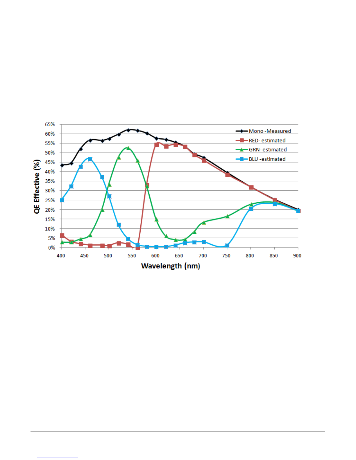
Responsivity & QE
The responsivity graph describes the camera‘s response to different wavelengths of light (excluding
lens and light source characteristics).
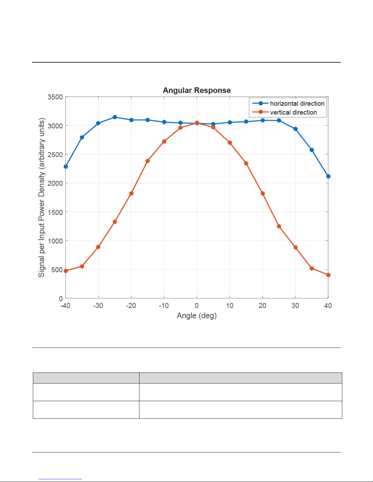
The image sensor includes micro lenses to improve the collection efficiency of the active pixel area.
The drawback to this is that the light collected varies with the angle of incidence, as shown in the
Angle of Incidence figure, below. Pixel Response Non Uniformity (PRNU) can be calibrated in the
field and takes into account the lighting and lens effects, and results in a more uniform output
level.
Figure 1: Camera Spectral Responsivity
8 Contents Falcon4 86M Cameras
Camera
Flash Memory Size
FA-S0-86M16-01-R
500 MByte program storage
8,000 MByte correction coefficients
FA-S1-86M16-00-R
500 MByte program storage
8,000 MByte correction coefficients
Angle of Incidence
Flash Memory Size
Falcon4 86M Cameras Contents 9
Figure 2: Angular Response
Table 7: Memory
Compliance
EN 55011, CISPR 11, EN 55022, EN 55032, CISPR 22, CISPR 32, FCC Part 15, and ICES-003 Class A Emissions
Requirements.
EN 55024, and EN 61326-1 Immunity to Disturbance.
Certifications & Compliance
Table 8: Radiated Emissions
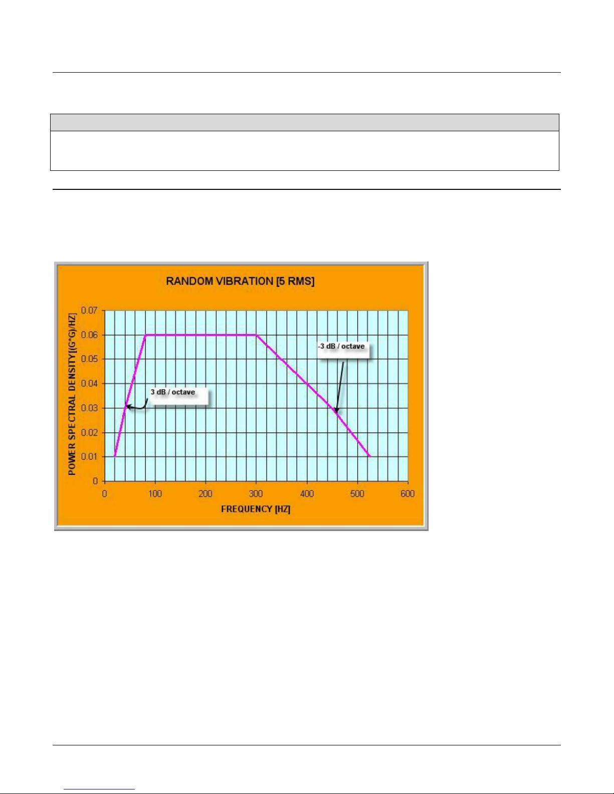
Shock & Vibration
The cameras meet or exceed the following specifications:
Random vibration per MIL-STD-810F at 25 G
Shock testing 75 G peak acceleration per MIL-STD-810F
2
/HZ [Power Spectral Density] or 5 RMS
10 Contents Falcon4 86M Cameras
RXC
TXC
TX1
TX2
TX3
TX4
TX5
TX6
TXC
RXC
RX1
RX2
RX3
RX4
RX5
RX6
Data Lane 6
Data Lane 0
Command
Channel
Video
Channel
Link
Camera
(C2,7M1)
Frame Grabber
(C2,7M1)
Supported Industry Standards
GenICam™
The camera is GenICam compliant and implements a superset of the GenICam Standard Features
Naming Convention specification V1.5.
This description takes the form of an XML device description file using the syntax defined by the
GenApi module of the GenICam specification. The camera uses the GenICam Generic Control
Protocol (GenCP V1.0) to communicate over the Camera Link HS command lane.
For more information see www.genicam.org.
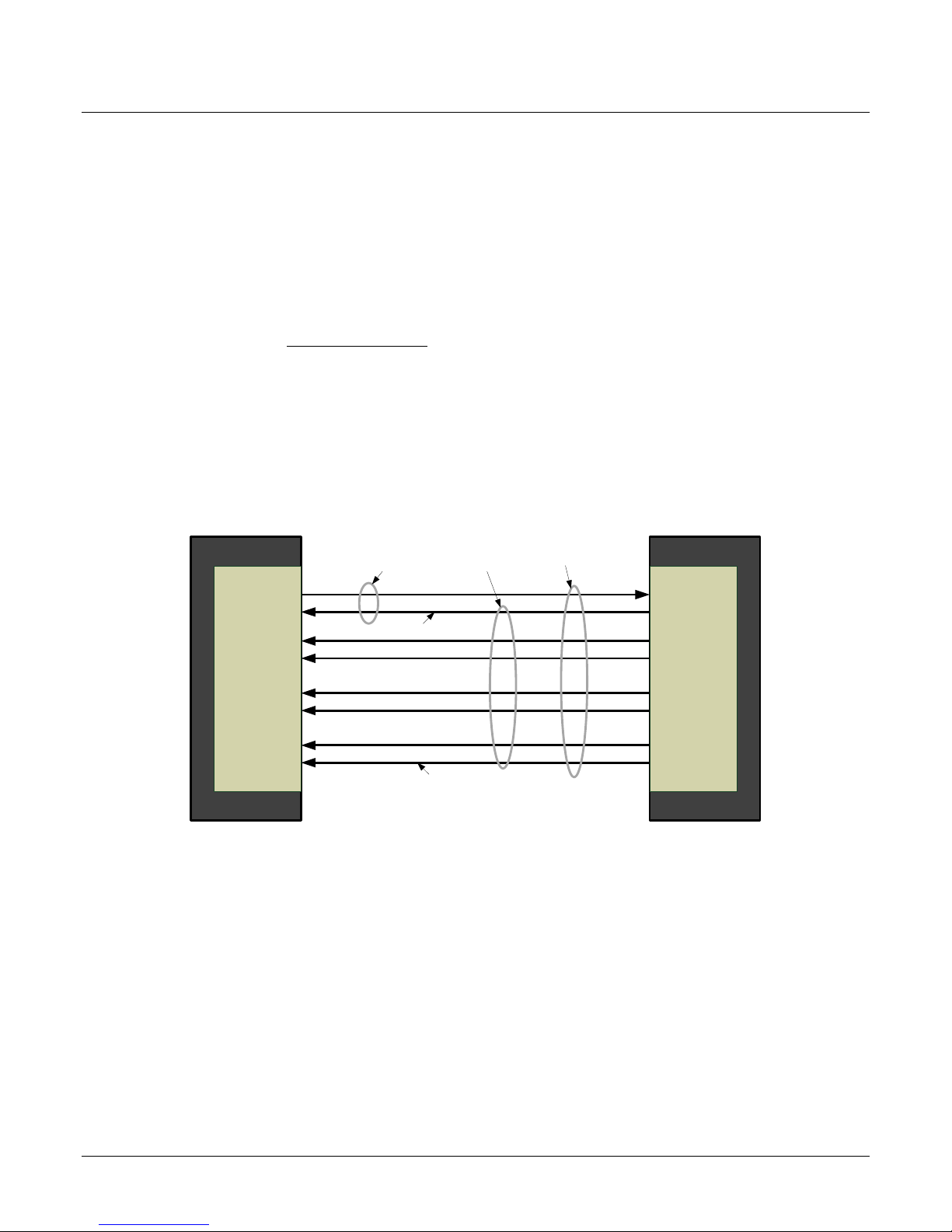
Camera Link HS
The camera is Camera Link HS version 1.0 compliant. Camera Link HS is the next generation of
high performance communications standards and is used where a digital industrial camera
interfaces with single or multiple frame grabbers with data rates exceeding those supported by
Camera Link. The camera includes a Camera Link HS connector capable of supporting data rates up
to 2.1 Gbytes / sec per second.
Figure 3. Single CLHS Connector Configuration
The command channel is used by the frame grabber to send command, configuration, and
programming data to the camera and to receive command responses, status, and image data from
the camera.
The designation C2, 7M1 defines the use of a SFF-8470 connector (C2) and up to 7 lanes of data
with 1 command channel using M-Protocol (8b/10b) at the default speed of 3.125 Gb/sec.
Camera Link HS ROI Characteristics
The single ROI is customer entered and transmitted across all seven data lanes. There is a
minimum of 96 pixels per data lane used.
Falcon4 86M Cameras Contents 11
CLHS limits the start and stop location of the ROI to a multiples of 32 pixels. The maximum line
rate is limited by the sensor when not limited by the CLHS cable or by the PCIe transfer. The sensor
is limited to a 125 kHz maximum line rate.
The CLHS cable has approximately 2.1 GByte / sec bandwidth for seven lanes. The XTIUM X8 frame
grabber has about 3.2 GByte / sec across the PCIe bus and can support the full frame rate of the
camera.
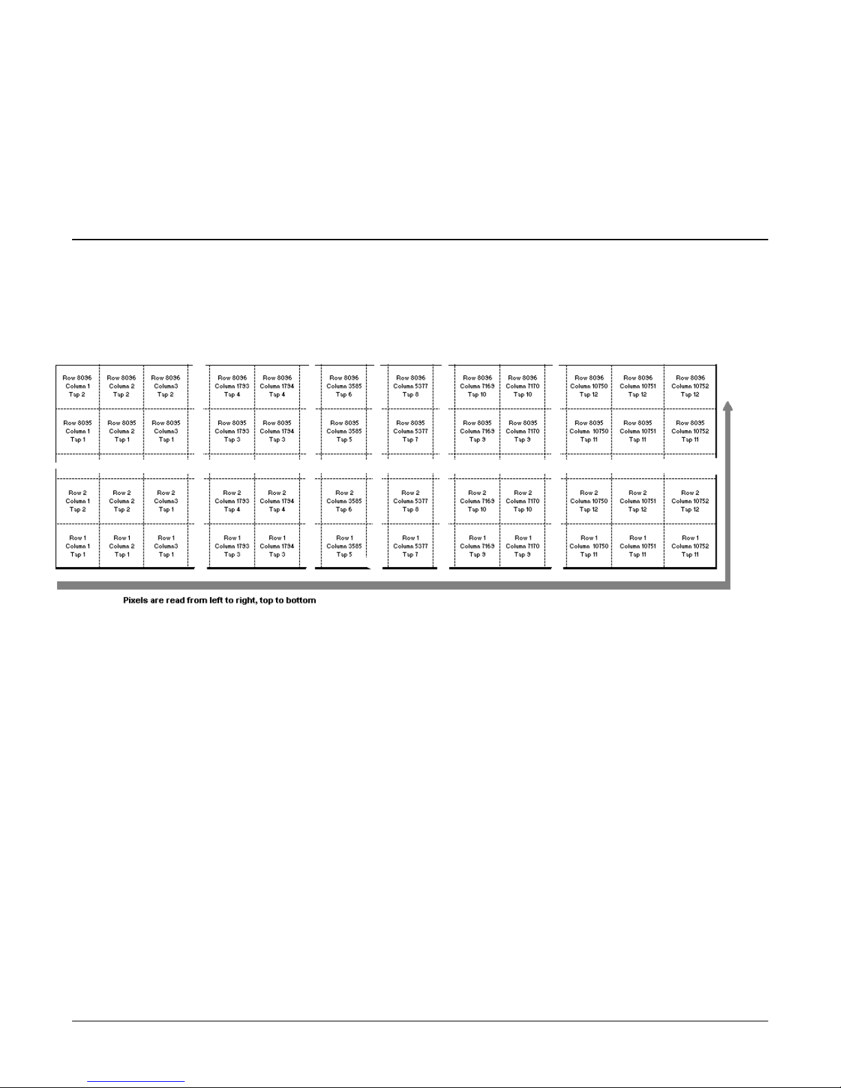
Sensor Block Diagram & Pixel Readout
Pixels are read from left to right, top to bottom. The data for each line is transferred from the
sensor to 7 CLHS data lanes. CLHS is a packet-based protocol therefore the concept of taps or tap
geometry does not apply; the frame grabber reconstructs the images based on the information
contained in the packet, regardless of which data lane is used for the transfer.
Figure 4: Pixel Readout of the Falcon 4 camera.
Note:
As viewed looking at the front of the camera without a lens. (The Teledyne DALSA logo on
the side of the case will be right-side up.)
12 Contents Falcon4 86M Cameras

Do not open the housing of the camera. The warranty is voided if the housing is
opened.
Camera Setup
System Precautions & Cleaning
Precautions
Read these precautions and this manual before using the camera.
Confirm that the camera‘s packaging is undamaged before opening it. If the packaging is
damaged please contact the related logistics personnel.
Keep the camera‘s front plate temperature in a range of 0 °C to 50 °C during operation. The
camera has the ability to measure its internal temperature. Use this feature to record the
internal temperature of the camera when it is mounted in your system and operating under
the worst case conditions. The camera will stop outputting data if its internal temperature
reaches 70 °C. Refer to section Verify Temperature for more information on the
‗Temperature‘ feature and thermal management.
Do not operate the camera in the vicinity of strong electromagnetic fields. In addition, avoid
electrostatic charging, violent vibration, and excess moisture.
Though this camera supports hot plugging, it is recommended that you power down and
disconnect power to the camera before you add or replace system components.
Cleaning the Device
To clean the device, avoid electrostatic charging by using a dry, clean absorbent cotton cloth
dampened with a small quantity of pure alcohol. Do not use methylated alcohol.
To clean the surface of the camera housing, use a soft, dry cloth. To remove severe stains use a
soft cloth dampened with a small quantity of neutral detergent and then wipe dry. Do not use
volatile solvents such as benzene and thinners, as they can damage the surface finish.
Electrostatic Discharge and the CMOS Sensor
Image sensors and the camera bodies housing are susceptible to damage from electrostatic
discharge (ESD). Electrostatic charge introduced to the sensor window surface can induce charge
buildup on the underside of the window. If this occurs, the charge normally dissipates within 24
hours and the sensor returns to normal operation.
Falcon4 86M Cameras Contents 13

Note: the use of cables types and lengths other than those specified may result in
increased emission or decreased immunity and performance of the camera.
Software and Hardware Setup
Recommended System Requirements
To achieve best system performance, the following minimum requirements are recommended:
High bandwidth frame grabber. For example, Teledyne DALSA Xtium PX8 CLHS series frame
grabber: http://www.teledynedalsa.com/imaging/products/fg/#digital-cameralink.
Operating systems: Refer to frame grabber documentation for supported platforms.
Setup Steps: Overview
Take the following steps in order to setup and run your camera system. They are described briefly
below and in more detail in the sections that follow.
1. Install and Configure Frame Grabber and Software.
2. Connect Camera Link and Power Cables.
3. Establish communication with the camera.
Step 1: Install and Configure Frame Grabber and Software
Teledyne DALSA recommends its Xtium PX8 CLHS series frame grabber or equivalent. Follow the
manufacturer‘s installation instructions.
A GenICam™ compliant XML device description file is embedded within the camera firmware
allowing GenICam™ compliant application to know the camera‘s capabilities immediately after
connection.
Installing Sapera LT gives you access to the CamExpert GUI, a GenICam™ compliant application.
Sapera LT is available free of charge for download from the Teledyne Dalsa website.
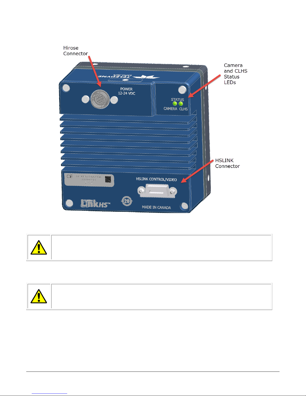
Step 2: Connect Camera Link and Power Cables
The camera uses a Camera Link HS SFF-8470 (CX4) cable and a Hirose connector for power and IO
connections.
Connect the required Camera Link HS cable from the camera to the frame grabber installed
on the computer.
Connect a power cable from the camera to a power supply that can provide a constant
voltage from +12 V to +24 V DC.
14 Contents Falcon4 86M Cameras
WARNING! Grounding Instructions
Static electricity can damage electronic components. It‘s critical that you discharge
any static electrical charge by touching a grounded surface, such as the metal
computer chassis, before performing handling the camera hardware.
WARNING: It is extremely important that you apply the appropriate voltages to
your camera. Incorrect voltages may damage the camera. Input voltage
requirement: +12 V to +24 V DC (± 5 %), 3.5 Amps. Before connecting power to
the camera, test all power supplies.
Figure 5: Input and Output, trigger, and Power Connectors
Power Connector
Falcon4 86M Cameras Contents 15
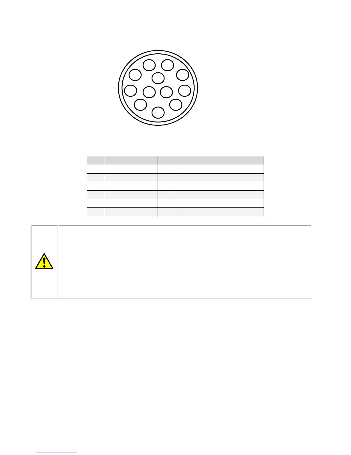
Pin
Description
Pin
Description
1
GND
7
OUT2+
2
+12 V to +24 V DC
8
OUT2-
3
OUT1-
9
NC 4 OUT1+
10
NC 5 IN1-/Trigger
11
IN2+/Trigger
6
IN1+/Trigger
12
IN2-/Trigger
WARNING: When setting up the camera‘s power supplies follow these guidelines:
Apply the appropriate voltages.
Protect the camera with a 3.5 amp slow-blow fuse between the power supply
and the camera.
Do not use the shield on a multi-conductor cable for ground.
Keep leads as short as possible in order to reduce voltage drop.
Use high-quality linear supplies in order to minimize noise.
Note: If your power supply does not meet these requirements, then the camera
performance specifications are not guaranteed.
1 2 3 4 6 7 8
9
10
11
12
Figure 6: 12-pin Hirose Circular Male Power Plug—Power Connector
Table 9. Power Plug Pinout
Camera Link Data Connector
The camera uses a Camera Link HS SFF-8470 (CX4) cable.
Input Signals, Camera Link
The camera accepts control inputs through the Camera Link HS SFF-8470(CX4) connector.
The camera ships (factory setting) in internal sync, and internally triggered integration.
Frame Start Trigger (EXSYNC)
The EXSYNC signal tells the camera when to integrate and readout the image. It can be either an
internally generated signal by the camera, or it can be supplied externally by a CLHS Pulse
Message software command or camera GPIO pin.
16 Contents Falcon4 86M Cameras

Color of Camera Status LED
Meaning
Off
No power or hardware malfunction
Red slow blinking
Camera in temporary shutdown (e.g. temperature). The communication channel is
maintained but imaging is disabled
Red solid
Fatal error state. Device is not functional
Blue fast blinking
Firmware upgrade, file transfer
Blue slow blinking
Camera waiting for warm up to complete (Camera initialization)
Blue solid
Upgrading internal firmware, when acquisition is disabled. This happens when changing a
camera feature that effects the image output (e.g. AOI, bit depth, etc.)
Green solid
Free-running acquisition
Green slow blinking
Calibration in progress
Orange slow blinking
Camera initializing
Color of CLHS Status LED
Meaning
Off
No power or hardware malfunction
Orange solid
The frame grabber is holding this device in reset preventing any communication
Orange slow blinking
The devices have established communication and determined that they are not
interoperable, and camera is initializing
Red solid
Fatal error state. Device is not functional.
Red slow blinking
Camera in temporary shutdown (e.g. temperature). The communication channel is
maintained but imaging is disabled
Red fast blinking
Camera has CLHS link error.
Green solid
Link established and data transfer may take place.
Green fast blinking
Camera is losing trigger
Green slow blinking
Looking for Link
Status
LED
CLHS
Status
LED
Initial power up
Camera initializing
(slow blinking)
Link established
Camera waiting for trigger
(fast blinking)
Initial power up
Camera initializing
(slow blinking)
Camera in free-running mode
Waiting for command
LED Indicators
The camera is equipped with 2 LEDs on the back to display the operational status of the camera.
The tables below summarize the operating states of the camera and the corresponding LED states.
When more than one condition is active, the LED indicates the condition with the highest priority.
LED States on Power Up
The following LED sequence occurs when the Falcon 4 is powered up connected to a CLHS frame
grabber.
Falcon4 86M Cameras Contents 17

Step 3: Establish Communication between the frame grabber and the
camera
To establish communication with the camera following these steps in order:
1. Power on the camera.
2. Connect to the frame grabber.
3. Connect to the camera.
1. Power on the camera
Turn on the camera‘s power supply. You may have to wait up to 60 seconds for the camera
to warm up and prepare itself for operation.
The camera must boot fully before it will be recognized by the GenCP compliant application.
In this ready-state, the CLHS LED will be green and the Camera LED will be green or blue (if
using a Teledyne DALSA frame grabber). You are now ready to connect the frame grabber,
step 2.
2. Connect to the frame grabber
Start Sapera CamExpert (or an equivalent GenCP-compliant interface) by double-clicking
the desktop icon created during the software installation.
CamExpert will search for Sapera devices installed on your system. In the Devices list area
on the left side of the GUI, the connected frame grabber will be shown. (See image below.)
Select the frame grabber device by clicking on its name.
Note: The first time you set up the camera you will need to establish a communication link between
the camera and frame grabber. Instructions are available in Appendix B: Camera, Frame Grabber
Communication.
3. Connect to the camera
Start a new Sapera CamExpert application (or equivalent Camera Link compliant interface)
by double-clicking the desktop icon created during the software installation.
Important: you need to have two interface windows open: one connected to and controlling
the frame grabber, and one connected to and controlling the camera. (See image below.)
CamExpert will search for Sapera devices installed on your system. In the Devices list area
on the left side of the GUI, the connected Falcon4 camera will be shown.
Select the Falcon4 camera device by clicking on the camera‘s user-defined name. By default
the camera is identified by its serial number.
18 Contents Falcon4 86M Cameras
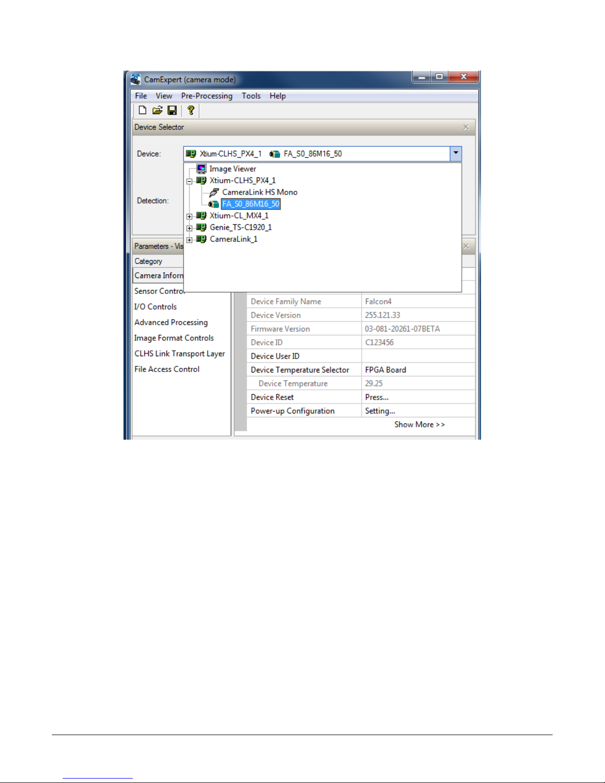
Figure 7: Frame grabber and connected camera shown
Check LED Status
At this point, if the camera is operating correctly the LEDs will flash yellow for approximately 10
seconds and then turn solid green if acquisition is on, or camera LED stays blue, CLHS LED blinks
green to wait for trigger
Software Interface
All the camera features can be controlled through the GUI. For example, under the Sensor Control
menu in the camera window you can control the frame rate and exposure times.
Note: the camera uses two instances of CamExpert. One window controls the camera and one
displays the output received from the frame grabber.
Also Note: If CamExpert is running during a camera reset operation, then you will have to reload
the GUI window used to control the camera once the camera is powered up again. Do this by
either: 1) closing and reopening the CamExpert window, or 2) by going to ―Image Viewer‖ in the
―Device‖ tab and selecting the camera again.
Falcon4 86M Cameras Contents 19

Figure 8: Two CamExpert windows shown: one connected to the frame grabber and one connected to the
camera
At this point you are ready to start operating the camera in order to acquire images, set camera
functions, and save settings.
20 Contents Falcon4 86M Cameras

Note: The examples shown may not entirely reflect the features and parameters available from
the camera model and camera mode used in your application.
Using CamExpert
The Sapera CamExpert tool is the interfacing tool for GenCP compliant Camera Link cameras, and is
supported by the Sapera library and hardware. When used with a CLHS camera, CamExpert allows
a user to test most of the operating modes. Additionally, CamExpert is able to save and reload the
FG configuration to simplify repeated power-up system configuration. Similarly, the camera is able
to store the selected camera configuration in a user set which can be recalled each time the camera
is repowered.
An important component of CamExpert is its live acquisition display window which allows
immediate verification of timing or control parameters without the need to run a separate
acquisition program.
Click on any parameter and a short description is displayed below the Category pane. The same
context sensitive help is available by clicking on the button then click on a camera
configuration parameter. Click on the button to open the help file for more descriptive
information on CamExpert.
CamExpert Panes
The various areas of the CamExpert tool are described in the figure below. Device Categories and
Parameter features are displayed as per the device‘s XML description file. The number of
parameters shown is dependent on the View mode selected (Beginner, Expert, Guru – see
description below).
Falcon4 86M Cameras Contents 21
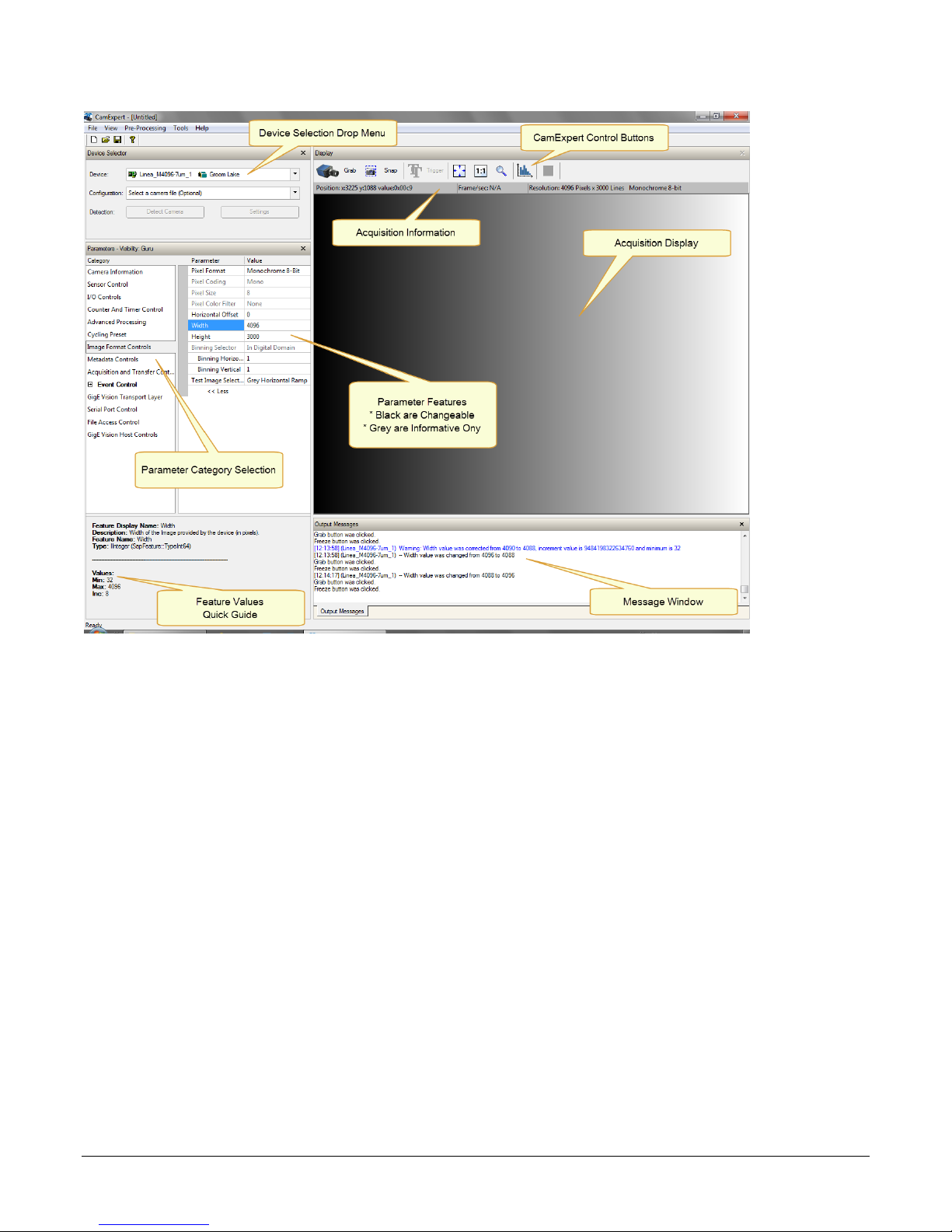
Device Selector pane: View and select from any installed Sapera acquisition device. After a
device is selected, CamExpert will only present parameters applicable to that device. Optionally
select a camera file included with the Sapera installation or saved by the user.
Parameters pane: Allows viewing or changing all acquisition parameters supported by the
acquisition device. CamExpert displays parameters only if those parameters are supported by
the installed device. This avoids confusion by eliminating parameter choices when they do not
apply to the hardware in use.
Display pane: Provides a live or single frame acquisition display. Frame buffer parameters are
shown in an information bar above the image window.
Control Buttons: The Display pane includes CamExpert control buttons. These are:
22 Contents Falcon4 86M Cameras

Acquisition control button:
Click once to start live grab, click again to stop.
Single frame grab:
Click to acquire one frame from device.
Software trigger button:
With the I/O control parameters set to Trigger Enabled / Software Trigger
type, click to send a single software trigger command.
CamExpert display controls:
(these do not modify the frame buffer data)
Stretch (or shrink) image to fit, set image display to original size, or zoom
the image to any size and ratio. This does not affect the acquisition.
Histogram / Profile tool:
Select to view a histogram or line/column profile during live acquisition.
Output pane: Displays messages from CamExpert.
CamExpert View Parameters Option
All camera features have a Visibility attribute which defines its requirement or complexity. The
states vary from Beginner (features required for basic operation of the device) to Guru (optional
features required only for complex operations).
CamExpert presents camera features based on their visibility attribute. CamExpert provides quick
Visibility level selection via controls below each Category Parameter list [ << Less More >> ]. The
user can also choose the Visibility level from the View ∙ Parameters Options menu.
Creating a Camera Configuration File in the Host
When using the Teledyne DALSA Sapera SDK – the CCF is created automatically via a save.
When using a 3
automatic. Simply follow the 3rd party Save Camera method as instructed.
If the SDK is based on GenAPI 2.3 or lower, the user must call the command
DeviceFeaturePersistenceStart before using the SDK Save Camera method and the command
DeviceFeaturePersistenceEnd at the end of the save function.
rd
party SDK application, if that SDK supports GenAPI 2.4, then the process is
Falcon4 86M Cameras Contents 23

Camera Operation
Factory Settings
The camera ships and powers up for the first time with the following factory settings:
Flat field coefficients enabled (calibrated in internal exposure mode, non-concurrent readout
and integration).
Defect concealment enabled.
Internal exposure mode (internal frame rate and exposure time).
12 Hz frame rate and 10 msec exposure time.
Dark row subtract enabled with the nominal background add value set
Check Camera and Sensor Information
Camera and sensor information can be retrieved via a controlling application—for example, the
CamExpert GUI shown in the following examples. Parameters such as camera model, firmware
version, sensor characteristics, and so forth, are read to uniquely identify the connected device.
The parameters used to select, load and save user sets are grouped together under the Camera
Information category.
Verify Temperature
To determine the temperature at the camera, use the Refresh Temperature feature. The Device
Temperature selector allows you to select which temperature sensor to read (FPGA, sensor board or
sensor). The temperature returned is the internal temperature in degrees Celsius. For proper
operation this value should not exceed 70 °C. If the camera exceeds the designated temperature it
will stop imaging and the LED will turn red. After you have diagnosed and remedied the issue use
the Device Reset function.
24 Contents Falcon4 86M Cameras

Warning! Depending on the mounting design and the operating conditions the
camera body could become hot. You must take precautions to ensure your
safety and avoid touching the camera directly during operation.
!
Thermal Management
The camera is designed to work with a maximum case temperature of 50 ºC. If the camera is left
powered on a bench, without lens, heat sinking, or forced air movement, the camera will become
very hot to the touch and will reduce its power dissipation by disabling the imaging function.
If this occurs, the LED turns red and communication with the camera is still available.
An accessory is available (part number AC-MS-00117-00-R, shown below) that mounts a fan to the
camera case to force air flow over the camera‘s heat sink. This accessory can be ordered from
Teledyne DALSA.
The fan‘s electrical connection is via 2 pigtail wires. The red wire is hooked to a +14 V to +24 V
supply @ 150 mA max, 100 mA typ. The black wire is the power return. With a +24 V supply, the
temperature on the sensor board will be about 25 degrees above ambient, as measured by the
sensor board temperature sensor. A +14 V supply results in an approximately +30 ºC temperature
rise above ambient.
Handling
Falcon4 86M Cameras Contents 25

Saving and Restoring Camera Settings
The Power-up Configuration parameter opens a dialog allowing you to specify the camera
configuration to use on power up and to save current parameter settings.
When the user changes a camera parameter, the settings are stored in the camera‘s volatile
memory and will be lost if the camera resets or is powered down. To save these settings for reuse,
they must be saved to the camera‘s non-volatile memory using the User Set Save parameter.
Previously saved user setting (User Set 1 to 3) or the factory settings can be restored using the
User Set Selector and User Set Load parameters.
Either the Factory or one of the User settings can be specified as the Default Set by selecting it in
the User Set Default Selector. The chosen set is automatically loaded when the camera is reset or
powered up. It should also be noted that the value of Default Selector will automatically get save in
non-volatile memory whenever it is changed.
26 Contents Falcon4 86M Cameras

The relationship between these three settings is illustrated here:
Figure 9: Relationship between the Camera Settings
NOTE: If a test pattern is active when you save the User Set, the camera will turn off all digital
processing upon restart. For example:
Set the test image selector to FPN Diagonal Pattern.
Do FPN Calibration and save the coefficient set.
Change the FFC mode to ActiveAll.
Set the default selector to UserSet1.
Save User Set 1.
Power cycle the camera.
Reconnect to the camera through CamExpert.
The FFC mode will be Off when it should be ActiveAll.
Acquisition and Transfer Control Features
Use the commands grouped under the Acquisition and Transfer Control category to choose the
acquisition mode, start and stop acquisitions, and to monitor the acquisition status.
The latest Teledyne DALSA frame grabber driver issues the acquisition start command by default.
Falcon4 86M Cameras Contents 27

Test Pattern
Description
Grey Horizontal Ramp
Image is filled horizontally with an image that goes from the
darkest possible value to the brightest. The ramp repeats every
4096 horizontal pixels.
Grey Vertical Ramp
Image is filled vertically with an image that goes from the
darkest possible value to the brightest. The ramp repeats every
4096 vertical pixels.
Purity
Image is filled with an image that goes from the darkest
possible value to the brightest by 1 DN increment per frame
(12-bit output).
Test Patterns
When setting test patterns, the camera set the digital gains to 1x, the digital offsets to 0, and
deactivates the flat field correction. This ensures that the test patterns appear as they should. At
the same time, the camera saves the last set of values that were used for video processing and
restores them when video output is restored.
Use CamExpert to easily enable and select any test pattern from the drop menu while the camera is
not in acquisition mode. Select live grab to see the pattern output.
The Test Pattern feature is available in the Image Format category:
28 Contents Falcon4 86M Cameras

Gray Diagonal Ramp
This test pattern is the sum of the horizontal and vertical test
patterns.
Static Value
All pixels are set to testImageStaticValue
PRNU
This is the 2 times the sum of a horizontal test pattern that
repeats every 64 pixels and a vertical test pattern that repeats
every 62 lines plus + testImageStaticValue. This test pattern
can be used to test FPN and PRNU correction.
Gain and Black Level Control Details
Gain and black level adjustments are available in the cameras. The analog black level and analog
gain are factory calibrated and not adjustable by the user. It is possible to optimize the image by
adjusting the digital offset controls and gain controls. The color camera features a per color gain
ahead of the system gain block. The user can evaluate gain and black level using CamExpert.
Note: The sensor digitizes at 12 bits and transfers the data across the link as 12 bit. If the data is
stored as 12 bit, then it is possible to optimize the image with post processing.
Falcon4 86M Cameras Contents 29

Description
Frame Rate
Exposure Time
Trigger Source
Internal frame rate and exposure
time
Internal, programmable
Internal programmable
Internal
External frame rate and exposure
time
Controlled by external
pulse
External
External
EXSYNC pulse controlling the frame
rate. Programmed exposure time.
Controlled by external
pulse
Internal programmable
External
Features and Limitations:
Analog Black Level offset is not available to the user.
Analog Gain is not available to the user.
[Digital Before FFC]Global FPN provides a constant component to the FPN Coefficients.
This value is calibrated in the factory but it can be adjusted relative to the factory setting (
factory setting). See the BlackLevel register‘s DigitalAll1 [Digital Before FFC] option. The
value is expressed as a floating point to allow for increased accuracy when processing a
frame sum of more than 1 frame.
[Digital After FFC] Background Subtract is a digital number that is used to reduce the
baseline pixel value. When combined with the system gain, this value is used to increase
contrast in the final output. See the BlackLevel register‘s DigitalAll2 [Digital After FFC]
option. The value is expressed as a floating point to allow for increased accuracy when
processing a frame sum of more than 1 frame.
System (Digital) Gain is expressed as a multiplication factor applied after the Color Gain
(color camera only) and any FFC stages. When combined with the background subtract, this
value is used to increase contrast in the final output.
Background Add is a number added to the image data before it is clipped at zero. This
value can be used to prevent the image clipping to zero. The factory uses the 2nd step FPN
algorithm for color cameras, where a small amount of light equal to (approximately 50 DN)
the least responsive channel is achieved and the FPN coefficient is recalculated. For a color
camera, the more responsive channels have about 130 DN output. The Background Add is
used to add this average level of signal back into the output value so that 0 light nominally
results in 0 output. The 2 step FPN is used to reduce errors in pixel values at low light level
due to nonlinear pixel behavior.
Exposure Controls
Exposure Control modes define the method and timing of how to control the sensor integration
period. The integration period is the amount of time the sensor is exposed to incoming light before
the video frame data is transmitted to the controlling computer.
Exposure control is defined as the start of exposure and exposure duration.
The start of exposure can be an internal timer signal (free-running mode), an external
trigger signal, or a software function call trigger.
The exposure duration can be programmable (such as the case of an internal timer) or
controlled by the external trigger pulse width.
The camera can grab images in one of three ways. The three imaging modes are determined using
a combination of the Exposure Mode parameters (including I/O parameters), Exposure Time and
Frame Rate parameters.
Figure 10: Exposure controls
30 Contents Falcon4 86M Cameras
Frame Time
Frame Time
Readout Time
Readout Time
Exposure Time
Exposure Time
Programmable
Programmable
Internally-generated
Exsync
Programmable
Programmable
FVAL
Internally Programmable Frame Rate and Internally Programmable Exposure
Time (Default)
Frame rate has priority over exposure time when adjusting the frame rate or exposure time. When
setting the frame rate, exposure time will decrease, if necessary, to accommodate the new frame
rate. When adjusting the exposure time the range is limited by the frame rate.
Note: The camera will not set frame periods shorter than the readout period and the frame rate is
limited to 12 Hz when sending 16 bit data and summing a single frame, due to cable bandwidth
limitations.
Camera Features:
TriggerMode = Off
AcquisitionFrameRate = 16 (for example)
ExposureMode = Timed
ExposureTime = 10000 (for example)
Figure 11: Internally Programmable Frame Rate and Internally Programmable Exposure Time (Default)
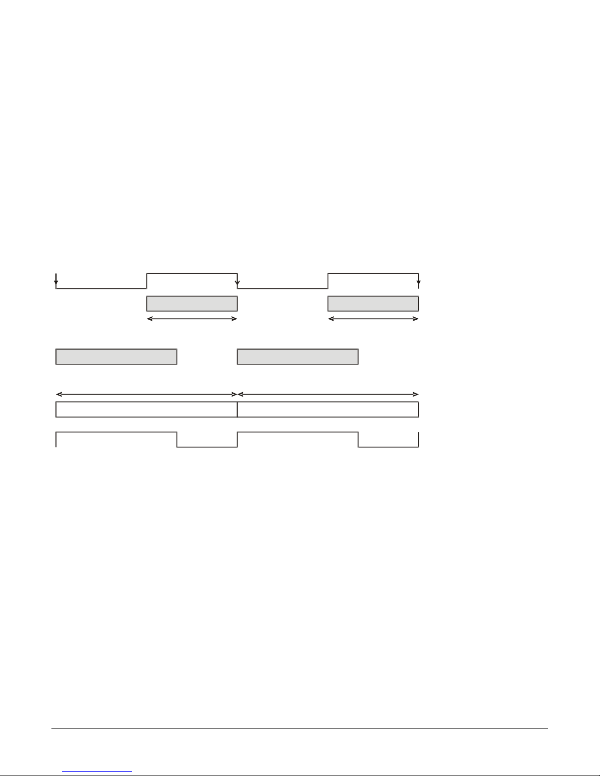
External Frame Rate and External Exposure Time (Trigger Width)
In this mode, EXSYNC sets both the frame period and the exposure time. The rising edge of
EXSYNC marks the beginning of the exposure and the falling edge initiates readout.
Camera Features:
TriggerMode = On
ExposureMode = Trigger Width
TriggerSource = GPIO Input 1
Falcon4 86M Cameras Contents 31

Frame Time Frame Time
Readout Time Readout Time
Exposure Time Exposure Time
User Exsync
FVAL
Figure 12: External Frame Rate and External Exposure Time (Trigger Width)
32 Contents Falcon4 86M Cameras

Frame Time
Frame Time
Readout Time
Exposure Time
Programmable
User Exsync
FVAL
Exposure Time
Programmable
Internally-generated Exsync
External Frame Rate, Programmable Exposure Time
In this mode, the frame rate is set externally with the falling edge of EXSYNC generating the rising
edge of a programmable exposure time.
Camera Features:
TriggerMode = On
ExposureMode = Timed
ExposureTime = 10000 (for example)
TriggerSource = GPIO Input 1
Figure 13: External Frame Rate, Programmable Exposure Time
Exposure Time
Exposure time is the amount of time that the sensor is allowed to accumulate charge before being
read. The user can set the exposure time when the ExposureMode feature is set to Timed. The
limitations on the maximum exposure time are listed below:
External Exposure Time: 100 µs (min) to 1 second (max).
Internal Exposure Time: (1 / frame rate) *0.95
Note: The maximum exposure time is dependent on the frame rate. To increase maximum
exposure time, decrease the frame rate. If using an internal exposure time with an external trigger,
it may be necessary to reduce exposure time to increase the frame rate.
Trigger Modes
The camera‘s image exposures are initiated by a trigger signal. The trigger event is either a
programmable internal signal used in free running mode, an external input used for synchronizing
exposures to external triggers, or a programmed function call message by the controlling computer.
These triggering modes are described below.
Free running (trigger disabled): The camera free-running mode has a programmable
internal timer for frame rate and a programmable exposure period.
Falcon4 86M Cameras Contents 33
External trigger: Exposures are controlled by an external trigger signal. The external trigger
signal can be either a Camera Link HS trigger message or a general purpose input (e.g.
GPIO [2 : 1]. General purpose inputs are isolated by an opto-coupler input with a time
programmable debounce circuit.
Software trigger: An exposure trigger is sent as a control command via the command
channel. Software triggers cannot be considered time accurate due to communications
latency and sequential command jitter.
Internal Frame Rate
The frame rate is dependent on the number of rows in read, and the summing mode. Frame rate
takes priority over exposure time. Maximum exposure time can be increased by lowering frame
rate.
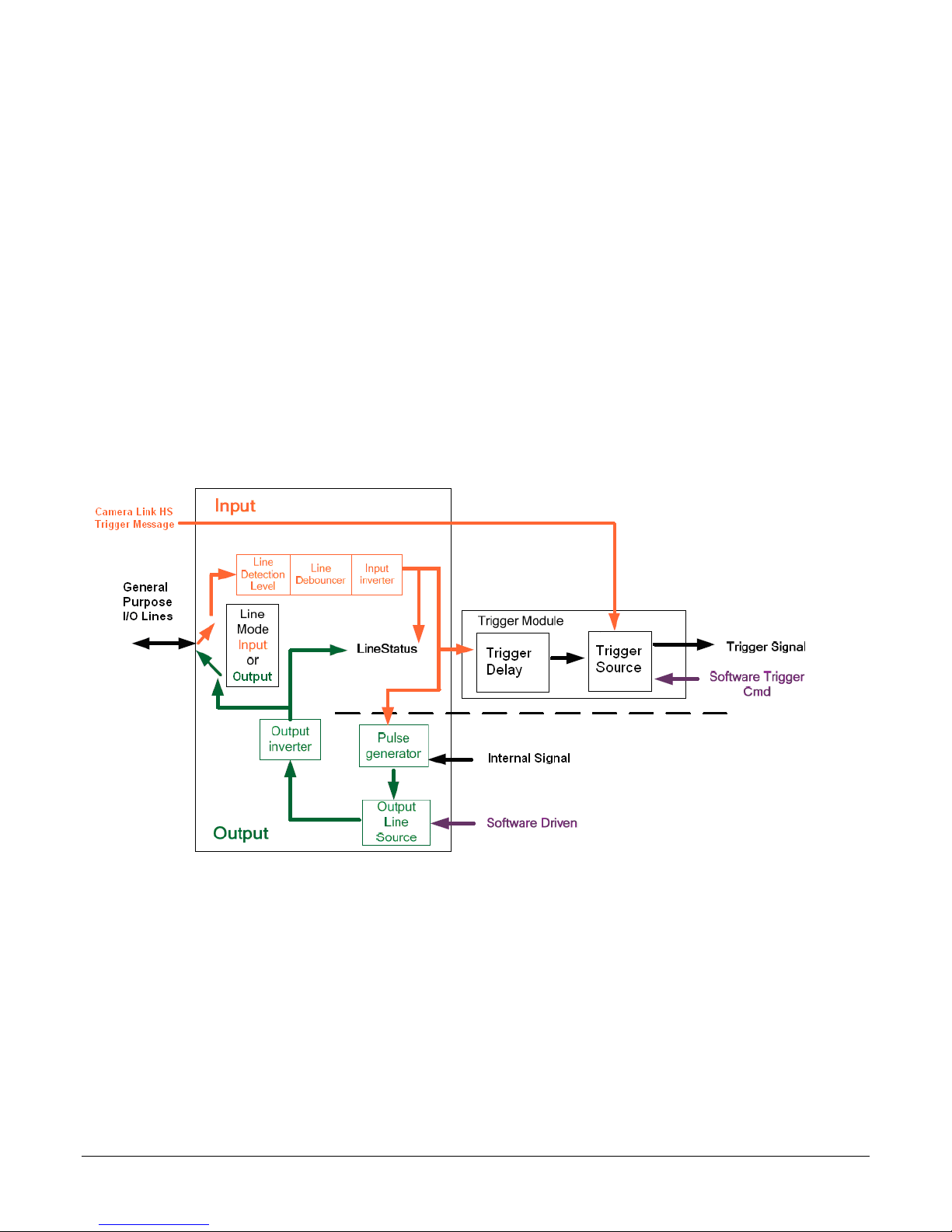
I/O Block Diagram
The following diagram describes the Input / Output features of the camera and how they are
related.
Opto-Coupled Inputs
The camera provides two sets of opto-isolated input signals. These can be used as external trigger
sources. The signals should be in range from 2.4 V to 24 V, 5 V typical. See the lineDetectionLevel
feature.
The delay between signals at the I / O pin and the internal timing core is a function of the signal
swing and the typical latency @ 5V swing is 3.5 µs.
34 Contents Falcon4 86M Cameras
Figure 14 I/O Module Block Diagram

Refer to Figure 6: 12-pin Hirose Circular Male Power Plug—Power Connector for the connector pin
out and electrical information. The cable shell and shield should electrically connect the camera
chassis to the computer chassis for maximum EMI protection.
Figure 15 Opto-coupled input
Each input incorporates a signal debounce circuit (following the opto-coupler) to eliminate short
noise transitions that could incorrectly be interpreted as a valid pulse. The duration is user
programmable from 1 µs to 255 µs using CamExpert.
Opto-Coupled Outputs
The outputs are unpowered devices and require external power. The simplified diagram below
demonstrates the need for a pull-up resistor (when using the outputs).
Figure 16: Simplified General Purpose Output Diagram
Falcon4 86M Cameras Contents 35

Flat Field Correction and Defective Pixel Detection
Overview
The Flat Field correction function consists of using two coefficients per pixel which correct the gain
and offset of the corresponding pixel. These corrections compensate for the Photo-response Nonuniformity (PRNU) and Fixed Pattern noise (FPN) attributes unique to each camera sensor. In
addition, the camera supports replacement of defective pixels (hot, dead, blinking) with a value
based on neighborhood pixels.
The Flat Field correction features are grouped in the Advanced Processing category:
Correction Function Block Diagram
The following simplified block diagram shows the processing chain that is applied to the image data
(the flat field and defective pixel blocks are highlighted). Note that each processing block can be
activated and deactivated independently. For example, the FPN and PRNU coefficients can be
applied independently or together using the flatfieldCorrectionMode.
Figure 17 Flat field and defective pixel processing
Dark Row Subtract Algorithm
The dark row subtract algorithm can be enabled, disabled, or set to off. The camera ships from the
factory with this feature enabled.
This algorithm improves the time stability of the FPN output from the sensor. The Dark Row
Subtract Mode Feature has 3 modes: Off, Disabled, Enabled.
36 Contents Falcon4 86M Cameras

When off, the dark rows from the image sensor are output in the first 32 rows of the image, the
image is shifted by 32 rows, and the top 32 rows of the image are not output. This mode is used to
measure and determine if any of the black rows are defective. Defective rows can be excluded
from the dark row subtract average using the Dark Row Defect Mask.
When disabled, the normal image is passed through this module without change.
When enabled, the average of the non-defective dark rows from the current and previous frame are
averaged on a per column basis and this average is subtracted from the raw sensor data. This
results in the average output of the column to be near zero and, as a result, the Dark Row Subtract
Digital Offset feature is used to add an offset back into the data so that no zero value clipping
occurs and FPN coefficients are correctly calculated. The camera ships with a value of 50 DN and
correction coefficients are calculated with the function enabled. Users need to ensure that the FPN /
PRNU coefficients in use were calculated with the current setting of the Dark Row Subtract
Algorithm.
Flat Field Correction Algorithm Description
Flat Field Correction Algorithm (feature: flatfieldCorrectionAlgorithm) applies the following FFC
formula for correcting pixel values:
newPixelValue
FFCGain
x,y
Where:
x & y are the Flat Field Correction Pixel coordinates. (See the
flatfieldCorrectionPixelXCoordinate and flatfieldCorrectionPixelYCoordinate features.)
newPixelValue is the pixel value after Flat Field Correction is applied.
sensorPixelValue is the pixel value before Flat Field correction is applied.
FFCOffsetBase is one offset coefficient value to subtract from the sensorPixelValue, this
value is measured at minimal exposure time.
FFCOffsetDelta is another offset coefficient value to subtract from the sensorPixelValue.
This value is measured at current exposure time, and is the deviation from FFCOffsetBase.
The normalization operation scales the stored FFCOffsetDelta by multiplying (current
integration time) / (calibration integration time). FFCOffsetDelta is measured immediately
after FFCOffsetBase.
FFCGain is the gain coefficient value that is multiplied with the sensorPixelValue.
The implementation of this formula requires that both the FPN and PRNU coefficient are stored in
32 bits. Internally in Falcon4, we reserve 9 bits for the FFCOffsetBase, 9 bits for FFCOffsetDelta
(FPN) coefficient and 14 bits for the FFCGain (PRNU) coefficient.
= (sensorPixelValue
x,y
– FFCOffsetBase
x,y
x,y – normalized
FFCOffsetDelta
x,y
) *
General Notes on FFC calibration
The camera comes calibrated with two factory sets, one for each shutter mode. In addition to the
factory calibrations, the camera provides three user configurable FFC sets. These can be calibrated
and saved in the camera.
Another option is to perform the flat field correction in the frame grabber.
In either case, we recommend that you repeat the correction when a temperature change of
greater than 10 °C occurs.
For best results, ensure that:
Falcon4 86M Cameras Contents 37

In camera flat field calibration can take up to 10 minutes. CamExpert has a default
timeout of 20 seconds per command, which is too short for the FFC calibration to run
fully. You can change the default timeout by setting a command line argument in the
short-cut:
Right click on the short-cut in the start menu and select properties.
Add –timeout 600 to increase the command timeout to 10 minutes (See
below)
Repeat for desktop short-cut
Gain (PRNU) calibration has a clean, white reference. The quality of this reference is
important for proper calibration. White paper is often not sufficient because the grain in the
white paper will distort the correction. White plastic or white ceramic will lead to better
balancing.
Ambient light flicker (e.g. fluorescent lights) is sufficiently low not to affect camera
performance and calibration results.
The average pixel should be at least 20 % below the target output. If the target is too close,
then some pixels may not be able to reach full swing due to correction applied by the
camera.
When 6.25 % of pixels from a single row within the region of interest are clipped to zero or
max value, flat field correction results may be inaccurate.
Correction results are valid only for the Dark Row Subtract settings for which the coefficients
were calculated. If you change this value, it is recommended that you recalculate your
coefficients.
Appendix D has more details.
An important note on window blemishes
When flat field correction is performed, window cleanliness is paramount. The figure below shows
an example of what can happen if a blemish is present on the sensor window when flat field
correction is performed. The blemish will cast a shadow on the wafer. FFC will compensate for this
shadow by increasing the gain. Essentially FFC will create a white spot to compensate for the dark
spot (shadow). As long as the angle of the incident light remains unchanged then FFC works well.
However when the angle of incidence changes significantly (i.e. when a lens is added) then the
shadow will shift and FFC will makes things worse by not correcting the new shadow (dark spot)
and overcorrecting where the shadow used to be (white spot). While the dark spot can be
potentially cleaned, the white spot is an FFC artifact that can only be corrected by another FFC
calibration.
How to do an FFC Setup in the Camera
38 Contents Falcon4 86M Cameras

Figure 18: Setting the camera’s timeout value
The calibration is performed in two steps. The offset FPN (base and Delta) is determined first by
performing an averaging without any light. This calibration determines exactly how much offset to
subtract per pixel in order to obtain flat output when the sensor is not exposed to light.
If the calibration finds any defective pixels, where its FPN base value is greater than Pixel
Replacement Offset Threshold, or its PRNU value is greater than Pixel Replacement Gain Threshold,
the pixel can be replaced if Pixel Replacement Mode is Active.
The gain (PRNU) calibration is performed next to determine the multiplication factors required to
bring each pixel to the required value (target) for flat, white output. For the monochrome cameras,
the target is determined by the user (See flatfieldCalibrationTarget).
It is important to do the FPN correction first. Results of the FPN correction are used in the PRNU
procedure.
Let‘s work through a flat field calibration example:
1. The camera is placed in internal exposure and frame rate. Ensure that the area of
interest (AOI) is set to the full window (i.e. Width = SensorWidth and Height =
SensorHeight). No other exposure mode or AOI configuration will allow FFC calibration. See
ExposureMode, TriggerMode, OffsetX, OffsetY, Width, Height.
2. Settings such as frame rate, exposure time, etc. are set as close as possible to the actual
operating conditions. Set system gain [All Digital] to 1 and background subtract to 0,
as these are the defaults during FFC calibration. See GainSelector, Gain, BlackLevelSelector,
and BlackLevel.
3. Select correction active set to user flat field x. Go to flat field correction mode, select
calibration. See flatfieldCorrectionCurrentActiveSet, and flatfieldCorrectionMode.
4. Clear existing coefficients. See flatfieldCalibrationClearCoefficient.
5. It is recommended to set Dark Row Subtract function Enabled as this corrects for column
offsets every frame and improves camera stability over time. The FPN coefficient calculation
result is impacted by the Dark Row Subtract. It is the user‘s responsibility to ensure the
coefficient set in use was calculated with the current setting of the Dark Row Subtract
function. When enabling the Dark Row Subtract function, the DarkRowSubtract Digital Offset
should be set to 50.
6. Place the camera in the dark (e.g. cover the lens), select FPN Calibration Step No as First
Step and run FPN Calibration. This performs the FPN correction and saves the FPN
coefficients to temporary memory. See flatfieldCalibrationFPN. FPNCalibrationStepNo
Calibration mode enables both FPN and PRNU correction. Verify signal output is close to 0
DN.
Falcon4 86M Cameras Contents 39

7. Illuminate the sensor to 65% saturation for monochrome cameras. For color cameras, try to
adjust the light level equally above and below 55% for the most and least responsive color.
Ensure a high quality white reference is used.
8. Set the Flat Field Calibration Algorithm to PRNU: Customer Target.
9. Set flat field target to 80 % saturation (monochrome only). For color cameras, set the flat
field target to 1.2x the average of the highest responding color. See
flatfieldCalibrationTarget.
10. Run Gain (PRNU) calibration. See flatfieldCalibrationPRNU.
A defective pixel will be replaced if Pixel Replacement Mode is Active. A defective pixel is
defined as a pixel whose FPN base value is greater than Pixel Replacement Offset Threshold
or / and whose PRNU value is greater than Pixel Replacement Gain Threshold.
11. Save the flat field calibration: flatfieldCalibrationSave.
More information is found in Appendix D.
Defective Pixel Detection and Replacement
The camera has three methods of replacing pixels. Single pixel replacement uses the FFC
coefficients to mark pixels that will be replaced. Defective columns or rows marked as defective use
the median filter algorithm to replace the defect pixel. The dynamic pixel replacement algorithm
uses a median filter to replace a given pixel value with the median value when its original value is
above / below a threshold when compared to adjacent pixels of the same color. These three
methods can be individually controlled.
Single Pixel Replacement
This is a technique for the elimination of dead or hot pixels.
The camera uses the FFC coefficients to indicate which pixels need to be replaced. If a pixel has a
Gain (PRNU) coefficient that is greater than the defectivePixelReplacementGainThreshold then the
pixel will be marked for replacement. Additionally, a pixel will be replaced if its Base Offset (FPN)
coefficient that is greater than the offset pixel replacement threshold
(defectivePixelReplacementOffsetThreshold ). Lowering these thresholds will remove more pixels
with high gain and offset coefficients.
Most hot and dead pixels will be identified when a FPN or PRNU calibration is performed in camera.
The user can also manually mark a pixel for replacement by setting its Pixel Base Offset to 511.
The replacement algorithm is shown below in the Median Filter section.
Defective Columns and Row Replacement
Defective rows and columns are marked during factory calibration but users can add or remove
defective rows and columns to / from the list. The Pixel Replacement Mode can be set to Off, which
does not replace the defective rows and columns, or Active to hide defective rows and columns. To
clear all rows and columns from the list, use the Pixel Replacement Clear function. To add a
defective Row or Column the following steps are used:
1) Select Row or Column using the Pixel Row or Column Selector.
2) Set the Row or Column Id using the Pixel Replacement Row or Column Number field.
3) The modified list can be saved in a user set.
40 Contents Falcon4 86M Cameras

The median filter algorithm, below, is used to replace defection rows and columns.
Median Filter
Enable the median filter by setting the medianFilter to Active (Image Format Controls). Setting this
filter to Off disables the medianFilter.
When the Median Filter is Active, then the Median Filter Threshold value controls the decision to
replace the pixel value. Replacement occurs when a pixel‘s current value differs from the median
value of a 3 x 3 kernel by more than the threshold value. The pixel is replaced by the median value
of a 3 x 3 kernel.
The algorithm is described below for monochrome cameras. Color cameras use the pixels of same
color in the matrix.
1. 3X3 2D median filter algorithm
a. First step calculation the 5 elements median value Pm1 and Pm2
P1 P2 P3 P1 P3
P4 P5 P6 => P5 => Med{P1, P3, P5, P7, P9} => Pmx;
P7 P8 P9 P7 P9
P1 P2 P3 P2
P4 P5 P6 => P4 P5 P6 => Med{P2, P4, P5, P6, P8} => Pmc;
P7 P8 P9 P8
b. Second step calculation the 3 elements median
Med{P5, Pmx, Pmc} => Pm;
c. Third step check the threshold(8bit value and default=255)
if (|P5 – Pm| > threshold) then
P5 output <= Pm;
else
P5 output <= P5;
end if;
2. Defect Pixel Replacement 3x3 2D Replacement
Each pixel with input defect flag associated if the flag is 1 the pixel will be do the 2D median
filter but without check threshold.
File Access via the CamExpert Tool
1. Click on the “Setting…” button to show the file selection menu.
Falcon4 86M Cameras Contents 41

Figure 19 Initial File Access Control Dialog
2. From the Type drop menu, select the file type that will be uploaded to the camera.
3. From the File Selector drop menu, select the camera memory location for the uploaded data. This menu
presents only the applicable data locations for the selected file type.
4. Click the Browse button to open a typical Windows Explorer window.
5. Select the specific file from the system drive or from a network location.
6. Click the Download button to execute the file transfer from the Falcon4.
7. Note that firmware changes require a device reset command.
42 Contents Falcon4 86M Cameras

Technical Specifications
Mechanicals
Falcon4 86M Cameras Contents 43

Teledyne DALSA inc.
605McMurray Road,
Waterloo, Ontario, Canada,
N2V 2E9
EN55032 (2012)
Electromagnetic compatibility of multimedia equipment —
Emission requirements
EN55011 (2009)
with A1(2010)
Industrial, scientific and medical equipment — Radiofrequency disturbance characteristics — Limits and methods
of measurement
EN 61326-1 (2013)
Electrical equipment for measurement, control and laboratory
use — EMC requirements — Part 1: General requirements
EN 55024 (2010)
Information technology equipment — Immunity
characteristics — Limits and methods of measurement
CFR 47
Part 15 (2008), subpart B, for a class A product. Limits for digital
devices
ICES-003
Information Technology Equipment (ITE) — Limits and Methods of
Measurement
CISPR 11
Industrial, scientific and medical equipment - Radio-frequency
disturbance characteristics - Limits and methods of measurement
CISPR 32
Electromagnetic compatibility of multimedia equipment - Emission
requirements
EC & FCC Declaration of Conformity
We:
Declare under sole legal responsibility that the following products conform to the protection
requirements of council directive 2004/108/EC (2014/30/EU after April 2016) on the approximation
of the laws of member states relating to electromagnetic compatibility and are CE-marked
accordingly:
FA-SO-86M16-01-R and FA-S1-86M16-00-R
The products to which this declaration relates are in conformity with the following relevant
harmonized standards, the reference numbers of which have been published in the Official Journal
of the European Communities:
Further declare under our sole legal responsibility that the product listed also conforms to the
following international standards:
Note: this product is intended to be a component of a larger system.
Waterloo, Canada. 2015 Apr.13
Hank Helmond
Director, Quality Assurance
44 Contents Falcon4 86M Cameras

Display Name
Feature & Values
Description
Standard & View
Device Vendor
Name
DeviceVendorName
Displays the device vendor name. (RO)
Beginner
Device Model
Name
DeviceModelName
Displays the device model name. (RO)
Beginner
Device Family
Name
DeviceFamilyName
Displays the device family product name.
(RO)
Beginner
Device Version
DeviceVersion
Displays the device version. This tag will
also highlight if the firmware is a beta or
custom design. This is an automatically
generated number that specifically
identifies the software build. (RO)
Beginner
Firmware Version
DeviceFirmwareVersion
Displays the currently loaded firmware
version number. Firmware files have a
unique number and have the .cbf file
extension. (RO)
Beginner
Device ID
DeviceID
Displays the device’s factory set camera
serial number. (RO)
Beginner
Device User ID
DeviceUserID
Feature to store a user-programmable
identifier of up to 15 characters. The default
factory setting is the camera serial number.
(RW)
Beginner
Appendix A: GenICam
Commands
This appendix lists the available GenICam camera features. Access these features using the
CamExpert interface.
Parameters in gray are read only, either always or due to another parameter being disabled.
Parameters in black are user set in CamExpert or programmable via an imaging application.
Features listed in the description table but tagged as Invisible are typically reserved for Teledyne
DALSA Support or third party software usage, and not typically required by end user applications.
Additionally the Standard column will indicate which parameter is a member of the custom DALSA
Features Naming Convention (denoted by DFNC), versus the GenICam Standard Features Naming
Convention (SFNC not shown).
Camera Information Category
The camera information group provides general information about the camera. Parameters such as
camera model and firmware version uniquely identify the connected device. As well, temperature
can be monitored and user sets can be saved and loaded to and from the camera‘s non-volatile
memory using the features grouped here.
Camera Information Feature Descriptions
The following table describes these parameters along with their view attribute.
Falcon4 86M Cameras Contents 45

Device
Temperature
Selector
DeviceTemperatureSelector
Select the source where the temperature is
read. (RW)
1.00
Beginner
FPGA Board
FPGABoard
Read FPGA Board temperature.
Sensor Board
SensorBoard
Read sensor board temperature.
Sensor
Sensor
Read sensor temperature.
Device
Temperature
DeviceTemperature
Displays the device temperature in degrees
Celsius.
Depending on the host application (e.g.
GUI). This value is a polled value and may
automatically be updated every second.
Otherwise the value will only be updated
upon connection or when the Refresh
Temperature selector is pressed.
Beginner
Refresh
Temperature
readTemperature
Refreshes the temperature reading. (W)
Device Voltage
DeviceVoltage
The applied voltage to the image sensor.
(RO)
User Set Default
Selector
UserSetDefaultSelector
Selects the camera configuration set to
load and make active on camera power-up
or reset. The camera configuration sets are
stored in camera non-volatile memory.
(RW)
Beginner
Factory
Factory
Load factory-calibrated defaults.
UserSet1
to
UserSet 4
UserSet1
to
UserSet4
Select the user defined configuration
(UserSet1 to UserSet8) as the Power-up
Configuration.
User Set Selector
UserSetSelector
Selects the camera configuration set to
load feature settings from or save current
feature settings to. The Factory set
contains default camera feature settings.
User camera configuration sets contain
features settings previously saved by the
user. (RW)
Beginner
Factory Set
Factory
Select the default camera feature settings
saved by the factory.
User Set 1
to
User Set 4
UserSet1
to
UserSet4
Select the User Defined Configuration
space (UserSet1 to UserSet8) to save to or
load from features settings previously
saved by the user.
User Set Load
UserSetLoad
Loads the camera configuration set
specified by the User Set Selector feature,
to the camera and makes it active. (W)
Beginner
User Set Save
UserSetSave
Saves the current camera configuration to
the user set specified by the User Set
Selector feature. The user sets are located
on the camera in non-volatile memory.
Disabled when flatfieldCorrectionMode =
Calibration or UserSetSelector = Factory.
(W)
Beginner
Device Reset
DeviceReset
Resets the device to its power up state.
(W)
Beginner
46 Contents Falcon4 86M Cameras

DFNC Major Rev
deviceDFNCVersionMajor
Major revision of Dalsa Feature Naming
Convention which was used to create the
device’s XML. (RO)
DFNC
Invisible
DFNC Minor Rev
deviceDFNCVersionMinor
Minor revision of Dalsa Feature Naming
Convention which was used to create the
device’s XML. (RO)
DFNC
Invisible
Device FPAG Info
deviceFPAGInfo
FPGA version information (date : time)
DFNC Invisible
Falcon4 86M Cameras Contents 47

Display Name
Feature & Values
Description
Standard
& View
Acquisition Mode
AcquisitionMode
Acquisition mode of the camera.
Beginner
Continuous
Continuous
Frames are captured continuously until stopped
with the Acquisition Stop command.
Acquisition Status
AcquisitionStatus
This feature reports if the camera is currently
transmitting image data. < RO >
Beginner
Acquisition Start
AcquisitionStart
Starts the acquisition of the device. The number
of frames captured is specified by Acquisition
Mode feature.
Beginner
Acquisition Stop
AcquisitionStop
Stops the acquisition of the device at the end of
the current frame(s) sequence.
Beginner
Display Name
Feature & Values
Description
Standard
& View
Device Scan Type
DeviceScanType
Scan type of the sensor. < RO>
Beginner
Area scan
Areascan
2D area scan sensor.
Sensor Color Type
sensorColorType
Defines the camera sensor color type. < RO
>
Beginner
DFNC
Monochrome Sensor
Monochrome
Sensor color type is monochrome. (RO)
CFA Bayer Sensor
CFA_Bayer
Sensor color type is Bayer Pattern.(RO)
Sensor Width
SensorWidth
Defines the sensor width in active pixels.
< RO>
Expert
Sensor Height
SensorHeight
Defines the sensor height in active lines.
< RO>
Expert
Acquisition and Transfer Control Category
The acquisition and transfer control category, as shown by CamExpert, group acquisition and
transfer specific parameters.
Acquisition and Transfer Control Feature Descriptions
The following table describes these parameters along with their view attribute.
Sensor Control Category
The camera sensor controls, as shown by CamExpert, group sensor specific parameters.
Sensor Control Feature Descriptions
The following table describes these parameters along with their view attribute.
48 Contents Falcon4 86M Cameras

Frame Rate
AcquisitionFrameRate
Specifies the camera internal frame rate, in
Hz. (Read-only when TriggerMode = "On")
1 to x Hz (where x is a calculated maximum)
The maximum value of the frame rate is the
result of a complicated formula and is
dependent on the following features:
Height, summingMode, pixelformat
Note that any user entered value is
automatically adjusted to a valid camera
value.
Beginner
Exposure Mode
ExposureMode
Sets the operation mode for the camera’s
exposure.
Beginner
Timed
Timed
The exposure duration time is set using the
Exposure Time feature and the exposure
starts with a LineStart event.
Trigger Width
TriggerWidth
Uses the width of the trigger signal pulse to
control the exposure duration. Use the
Trigger Activation feature to set the polarity of
the trigger.
The Trigger Width setting is active when the
Trigger Mode is On and a signal (e.g. Line 1)
is selected as the trigger source. These
features are found in the I/O Control
category.
Exposure Time
ExposureTime
Sets the exposure time (in microseconds)
when the Exposure Mode feature is set to
Timed.
Beginner
Gain Selector
GainSelector
Selects which channel’s gain is controlled
when adjusting gain features.
Beginner
All Digital
DigitalAll
Apply a digital gain adjustment to the entire
image.
Digital Red(Bayer
Camera Only)
DigitalRed
Digital Blue(bayer
Camera Only)
DigitalBlue
Digital Green
Blue(BayerCamera Only)
Digital Green Red
DigitalGreenBlue
DigitalGreenRed
Green pixels that share same row as blue.
Green pixels that share the same row as red.
Gain
Gain
Sets the selected gain as an amplification
factor applied to the image. (RW)
Beginner
Black Level Selector
BlackLevelSelector
Selects which black level (i.e. dark offset) is
controlled when adjusting the black level
feature.(RW)
Beginner
Digital Before FFC
DigitalAll1
Global FPN. Apply black level adjustment to
all digital channels or taps, before flat field
correction.
Digital After FFC
DigitalAll2
Background Subtract. Apply black level
adjustment to all digital channels or taps,
after flat field correction.
Background Add
BackgroundAdd
Add a digital value to the image before FFC
(tbc)
Falcon4 86M Cameras Contents 49

Black Level
BlackLevel
Sets the Black level (offset) in DN selected
by the BlackLevelSelector (RW)
Expert
Shutter Mode
shutterMode
Determines the exposure mode used by the
sensor (RW)
Guru
Global
Global
All pixels integrate simultaneously and then
held constant until they can be read. This is
at the cost of higher noise.
Rolling
Rolling
The rows of the sensor integrate light at
slightly different times. This can cause image
artifacts. Especially if the scene is moving.
50 Contents Falcon4 86M Cameras

Display Name
Feature & Values
Description
Standar
d
& View
Trigger Selector
TriggerSelector
Displays the type of trigger to configure with the
various Trigger features. <RO>
Beginner
FrameStart
FrameStart
Selects a trigger starting the capture of a single frame.
Trigger Mode
TriggerMode
Enables and disables external frame trigger.(RW)
Beginner
Off
Off
Use an internal trigger.
On
On
Use an external trigger. This option is not available
while in Calibration Mode.
Trigger Source
TriggerSource
Specifies the internal signal or input line to use as the
trigger source. (RW)
The trigger mode must be set to On.
Beginner
Software
Software
Software trigger through the TriggerSoftware
command.
LinkTrigger0
LinkTrigger0
CLHS trigger message from the FG.
Line1
Line1
General Purpose Input Line 1
Line2
Line2
General Purpose Input Line 2
Software Trigger
TriggerSoftware
Generate an internal trigger. Available when the
trigger mode is enabled and the trigger source is
equal to Software.(W)
Beginner
Trigger Delay
TriggerDelay
Specifies the delay in microseconds to apply after the
trigger reception before activating it. Possible values
are:
0 - 1*10^6µs
Beginner
LineSelector
LineSelector
Selects the logical line of the device to configure.(RW)
Beginner
General Purpose Input 1
Line1
General Purpose Input 1
General Purpose Input 2
Line2
General Purpose Input 2
General Purpose Output
1
Line3
General Purpose Output 1
General Purpose Output
2
Line4
General Purpose Output 2
Line Mode
LineMode
Returns if the selected physical pin is used as an input
or output signal. <RO>
Beginner
Input
Input
The selected physical pin is used as an input.
Output
Output
The selected physical pin is used as an output.
Line Pinout
linePinAssociation
Gets the physical pin location associated with the
logical line. The H1 prefix refers to the Hirose Power
and input cable (see Figure 6). <RO>
DFNC
Beginner
H1_Pin6Pos_Pin5Neg
H1_Pin6Pos_Pin5Neg
General Purpose Input 1:
Hirose Pin 6 Positive, Pin 5 Negative.
I / O Control Category
The camera‘s I / O controls, as shown by CamExpert, group features used to configure external
inputs and acquisition actions based on those inputs, plus camera output signals to other devices.
I/O Controls Feature Descriptions
The following table describes these parameters along with their view attribute.
Falcon4 86M Cameras Contents 51

H1_Pin11Pos_Pin12Ne
g
H1_Pin11Pos_Pin12Neg
General Purpose Input 2:
Hirose Pin 11 Positive, Pin 12 Negative.
H1_Pin3_Pin4
H1_Pin3_Pin4
General Purpose Output 1:
Hirose Pin 3, Pin 4.
H1_Pin7_Pin8
H1_Pin7_Pin8
General Purpose Output 2:
Hirose Pin 7, Pin 8.
Line Debouncing Period
lineDebouncingPeriod
Specifies the minimum length of an input line voltage
transition before recognizing a signal transition.
Available when the Line Selector is set to an input.
Each input line stores its own debouncing period.(RW)
Possible values are: 1 to 255 µs.
DFNC
Beginner
Line Inverter
Line Inverter
Controls whether to invert the selected input or output
line signal. (RW)
Beginner
True
True
Invert signal.
False
False
Do not invert signal.
Line Status
LineStatus
Returns the current status of the selected input or
output line. This is a polled feature that requires the
host to poll the camera for the latest value.(RO)
Beginner
True
True
Selected signal is high.
False
False
Selected signal is low.
Output Line Source
outputLineSource
Selects which internal signal or software control
state to output on the selected line. The pulse
is defined by outputLinePulseDelay and
outputLinePulseDuration.(RW)
Note: the Line Mode feature must be set to
Output.
DFNC
Beginner
Off
Off
The output line is open.
Software Controlled
SoftwareControlled
The value of the output line is determined by
outputLineValue,
outputLineSoftwareLatchControl and / or
outputLineSoftwareCmd.
Pulse On: Start of
Exposure
PulseOnStartofExposure
Generate a pulse when the sensor actually
starts exposing its pixels. (Slight delay after
EXSYNC).
Pulse On: End of
Exposure
PulseOnEndofExposure
Generate a pulse when the sensor stops
exposing its pixels.
Pulse On: Start of
Readout
PulseOnStartofReadout
Generate a pulse when the sensor starts
reading its pixels.
Pulse On: End of
Readout
PulseOnEndofReadout
Generate a pulse when the sensor stops
reading its pixels.
Pulse On: GP Input 1
PulseOnInput1
Generate a pulse when the General Purpose
Input 1 goes active.
Pulse On: GP Input 2
Pulse OnInput2
Generate a pulse when the General Purpose
Input 2 goes active.
52 Contents Falcon4 86M Cameras

Output Line Pulse
Duration (in Us)
outputLinePulseDuration
Sets the duration of the output pulse (RW)
1 to100, 000 µs
Note: LineMode feature must be set to Output
and outputLineSource is not equal to Off or
SoftwareControlled.
DFNC
Beginner
Output Line Value
outputLineValue
Selects the state of the output on the selected
line. (RW) The Value will be applied
immediately if the
outputLineSoftwareLatchControl feature is
equal to OFF.
The Value will be applied when the
outputLineSoftwareCmd feature is set if the
outputLineSoftwareLatchControl feature is
equal to LATCH.
Note: LineMode feature must be set to Output
and outputLineSource set to
SoftwareControlled.
DFNC
Beginner
Active
Active
Sets the Output circuit to close.
Inactive
Inactive
Inactive - Sets the Output circuit to open.
Line Detection Level
lineDetectionLevel
The voltage at which the signal is treated as a
logical high. Available when the Line selector is
set to a general purpose input (GPI). (RW)
Note: This value is for both general purpose
inputs (i.e. setting this value sets it for both
Line 1 and Line 2).
DFNC
Beginner
2.4V Threshold
Threshold_2_4
2.4V threshold: for TTL inputs
Threshold_6_0
Threshold_6_0
6V threshold: for 12V input
Threshold_12_0
Threshold_12_0
12V threshold: for 24V input
Line Status All
LineStatusAll
Returns the current status of all available line
signals, at time of polling, in a single bitfield.
This is a polled feature that requires the host to
poll the camera for the latest value. <RO>
The order is Line1(LSB), Line2, Line3, Line4/
7 6 5 4 3 2 1
0
Not used
Line
4
Line
3
Line
2
Line
1(LSB)
Beginner
Output Line Software
Latch Control
outputLineSoftwareLatchContro
l
The software latch allows the user to set more
than 1 output simultaneously(RW)
OutputLine that are currently in Software Latch
control will only set with the value in
OutputLineValue with the
outputLineSoftwareCmd feature.
DFNC
Beginner
Off
Off
Changes to the output line value are applied
immediately.
Latch
Latch
Changes to the output line value are applied
when the Output Line Software Command is
triggered.
Falcon4 86M Cameras Contents 53

Output Line Software
Command
outputLineSoftwareCmd
Contains a bit field representing whether to
apply to cached outputLineValue values. (W)
Value
0 Don‘t apply any value
1
Apply outputLineValue of Output1
2
Apply outputLineValue of Output2
3
Apply outputLineValue of Output1
and Output2
Note: LineMode feature must be set to Output
and outputLineSource is set
SoftwareControlled.
DFNC
Beginner
54 Contents Falcon4 86M Cameras

Display Name
Feature & Values
Description
Standard
& View
Correction Mode
flatfieldCorrectionMode
Sets the mode for flat field correction.(RW)
DFNC
Beginner
Off
Off
Flat field correction is disabled.
Active
ActiveAll
Flat field correction is enabled. FPN and
PRNU correction is active.
Active, FPN Only
ActiveFPNOnly
FPN correction is active.
Active, PRNU
Only
ActivePRNUOnly
PRNU correction is active.
Calibration
Calibration
The camera is configured to calibration
mode (Only available when TriggerMode =
Off, flatfieldCorrectionCurrentActiveSet is
not FactoryFlatfield,).
The device may automatically adjust some
features in the camera when calibration
mode is enabled. The features that are
automatically adjusted are device specific.
The device will not restore these features
when the flat field correction mode is
changed from calibration mode to another
mode.
It is not available for FactoryFlatfield1
[Global Shutter Factory Flat Field]
FactoryFlatfield2 [Rolling Shutter Factory
Flat Field].
It is not available for external mode, and it
is not available for AOI smaller than 2048
horizontal.
Current Active
Set
flatfieldCorrectionCurrentActiveSet
Specifies the current set of flat field
coefficients to use. This feature cannot be
changed while the camera is in flat field
calibration mode. Read-Write (Read-Only
when in Calibration Mode).
DFNC
Beginner
Global Shutter
Factory Flat Field
FactoryFlatfield1
Factory calibrated flat field for Global
Shutter Mode
Rolling Shutter
Factory Flat Field
FactoryFlatfield2
Factory calibrated flat field for Rolling
Shutter Mode.
User Flat Field 1
to
User Flat Field 3
UserFlatfield1
to
UserFlatfield3
User Flat Field 1 to User Flat Field 3: User
configurable flat field sets
Pixel X
Coordinate
flatfieldCorrectionPixelXCoordinate
Specifies the X coordinate of the flat field
pixel coefficient to access. (RW) To
configure, set Correction Mode to
Calibration. Range: 1 to SensorWidth
Beginner
Advanced Processing Control Category
The camera‘s Advanced Processing controls, as shown in CamExpert, group parameters used to
configure Defective Pixel Detection, Flat Field calibration.
Advanced Processing Control Feature Descriptions
The following table describes these parameters along with their view attribute.
Falcon4 86M Cameras Contents 55

Pixel Y
Coordinate
flatfieldCorrectionPixelYCoordinate
Specifies the Y coordinate of the flat field
pixel coefficient to access. (RW) To
configure, set Correction Mode to
Calibration. Range: 1 to SensorHieght
DFNC
Beginner
Pixel
Gain(PRNU)
flatfieldCorrectionGain
Sets the gain to apply to the currently
selected pixel. Range is from 1 to 4, as
float.
To configure, set Correction Mode to
Calibration.
Pixel Base
Offset(FPN)
flatfieldCorrectionOffsetBase
Sets the offset to apply to the currently
selected pixel. It is measured at the
minimal exposure time at dark.
To use, set the Correction Mode feature to
Calibration.
Beginner
Pixel Delta
Offset(FPN)
flatfieldCorrectionOffsetDelta
Sets the offset to apply to the currently
selected pixel. Measured at the current
exposure time at dark with a subtraction of
flatfieldCorrectionOffsetBase.
Range is 0 to 511, as float.
Read-Write when in Calibration Mode.
Clear
Coefficients
flatfieldCalibrationClearCoefficient
This feature is used to clear all the current
FPN and PRNU coefficients in the
selected Active Set. (W)
Read-Write when in Calibration Mode
DFNC
Expert
FPN calibration
step No
This feature selects the FPN calculation
method. (RW)
Step 1
When the Offset Calibration is
commanded, the base FPN value and the
delta FPN value are calculated.
Step 2
When the Offset Calibration is
commanded the base FPN value is
calculated and not the delta FPN. The
purpose is to enable calibration with a
small amount of light to avoid the nonlinear
behavior near zero illumination. A
recommended illumination level is 50 DN.
Offset(FPN)
Calibration
flatfieldCalibrationFPN
Performs fixed pattern noise (FPN)
calibration. FPN calibration eliminates
fixed pattern noise by subtracting all nonuniformities and dark current to obtain
near 0 DN output in the dark (no light
exposed to the sensor). This currently can
take up to 5 minutes.
Read-Write when in Calibration Mode
DFNC
Expert
56 Contents Falcon4 86M Cameras

AutoBrightness
OffsetY
autoBrightnessOffsetY
Sets the start of the area in the y direction
for pixels included in the color PRNU
Target average.(RW)
Is automatically increased if the OffsetY is
increased and has minimum value
OffsetY+2. This parameter increments in
multiples of 2
The autoBrightnessHeight may need to be
reduced before this value can be
increased.
autoBrightnessOffsetY <= OffsetY+Height
-4-autoBrightnessHeight.
AutoBrightness
OffsetX
autoBrightnessOffsetX
Sets the start of the area in the x direction
for pixels included in the color PRNU
Target average.(RW)
Has minimum value 0 and increments in
multiples of 32. Non multiples of 32 are
rounded down to the nearest multiple.
The autoBrightnessWidth may need to be
reduced to increase this value. The
minimum width is 64.
autoBrightnessOffsetX <= 10720autoBrightnessWidth.
AutoBrightness
Height
autoBrightnessHeight
Determines the number of rows to include
in the average used to set the PRNU
targets for color sensors.(RW)
The minimum autoBrightnessHeight is 4
rows and the maximum is Height-4. The
autoBrightnessheight is increased in
multiples of 2 and if an odd number is
entered, the entry will be rounded down
when possible. Also the
AutoBrightnessOffsetY may need to be
decreased before increasing this
parameter.
autoBrighitnessHeight =<OffsetY+Height2-autoBrightnessOffsetY
AutoBrightness
Width
autoBrightnessWidth
Determines the number of columns to
include in the average used to set the
PRNU targets for color sensors.(RW)
The minimum autoBrightnessWidth is 64
columns and the maximum is Width is
10720. The width is increased in multiples
of 32 and entries will be rounded down to a
multiple of 32. Also the
AutoBrightnessOffsetX may need to be
decreased before increasing this
parameter.
autoBrighitnessWidth <= 10720 autoBrightnessOffsetx
Flatfield
Calibration
Algorithm
flatfieldCorrectionAlgorithm
Selects the algorithm to use for calibration
of flat field PRNU coefficients. (RW)
DFNC
Beginner
Falcon4 86M Cameras Contents 57

PRNU: Customer
Target
PRNU_Customer_Target
The following formula is used to calculate
the flatfield corrected pixel:
Monochrome
During operation :
correctedPixelValuex,y =
(sensorPixelValuex,y – DarkRowSubtractFFCOffsetx,y –
currentIntTime/CalIntTime*DeltaFPNxy) *
FFCGain[x][y]
* The FPN coefficients must be calculated
with the intended DarkRowSubtractMode
(on or off)
FFCOffsetx,y = the average offset value
per pixel that is measured when the sensor
is dark at the minimum integration time,
with or without the DarkRowSubtract
function enabled.
DeltaFPNxy is average value per pixel
measured at the calibration integration
time –the FPNoffsetxy
FFCGainxy is calculated under
approximately 50% illumination and is the
result of the following calculation
FFCGainxy = Target/(Average signalxy –
DarkRowSubtract- FFCOffsetx,y –
currentIntTime/CalIntTime*DeltaFPNxy)
It is recommended that the target be set
20% higher than the average scene value.
Color
During operation the equation, when
enabled is
correctedPixelValuex,y =
(sensorPixelValuex,y – DarkRowSubtractFFCOffsetx,y –
currentIntTime/CalIntTime*DeltaFPNxy) *
FFCGain[x][y]
The dark offsets are calculated as above.
The PRNU coefficient is calculated using
customer entered per color targets. It is
recommended these values be 1.2x the
measured color average.
FFCGainxyr/g/b = Targetr/g/b/(Average
signalxy –
DarkRowSubtract- FFCOffsetx,y –
currentIntTime/CalIntTime*DeltaFPNxy)
White balance gains are set to unity and
saved with the coefficient set.
58 Contents Falcon4 86M Cameras

PRNU: Auto
Color Gain
PRNUautoColorGain
The calculation equations are the same as
above, however the target value is
determined by the camera over the Area of
Interest controlled by the entries of the
AutoBrightnessXXX parameters.
The target value is
Targetx = Averagex*1.2
Where x is the specific color/ or mono.
In this mode the white balance gains are
stored with the PRNU coefficients and are
set as WBgain most responsive color =1,
WBgainColor1/2= MostresponsiveColor /
(Color1/2Avg)
Gain Calibration
Target Selector
flatfieldColorTargetSelector
Selects the color PRNU target that the
Gain Calibration Target is applied to. (RW)
Mono cameras do not have this selector.
DFNC
Expert
TargetRed
TargetGreen
TargetBlue
Gain Calibration
Target
flatfieldCalibrationTarget
Sets the target pixel value for the gain
(PRNU) calibration for the respective color
when in calibration mode, method 1. (RW)
It is specified as a percentage of the
output range (for example, 2048 DN for 12
bits = 50%).
Range is 0 to 100 %, as float.
All three colors need to be entered for the
color camera and a single value entered
for the monochrome camera. It is
recommended the
flatfieldCalibrationTarget =
colorAverage*1.2.
PRNU calculation method 2 uses image
statistics to calculate the target values and
flatfieldCalibrationTarget is not used.
For Color Cameras: method 1 sets the
white balance gain factors to unity for the
PRNU coefficient set, while Method 2
stores the white balance gain factors
needed to achieve white balance.
DFNC
Expert
Calibration
Sample Size
flatfieldCalibrationSampleSize
The number of images to average to
perform the calibration.(RW)
DFNC
Beginner
Average 256
images
Avg256
Average 256 images. Recommended for
PRNU calculation.
Average 128
images
Avg128
Average 128 images. Recommended for
FPN calculation.
Average 64
images
Avg64
Average 64 images.
Average 32
images
Avg32
Average 32 images.
Average 16
images
Avg16
Average 16 images.
Read-Write when in Calibration Mode.
Falcon4 86M Cameras Contents 59

Gain(PRNU)
Calibration
flatfieldCalibrationPRNU
Performs photo response non-uniformity
(PRNU) calibration. (W)
PRNU calibration eliminates the difference
in responsivity between the most and least
sensitive pixel, creating a uniform
response to light. Pixels that fall outside
gain range of 1 to 4 for their color are
marked as defective.
Write when in Calibration Mode
DFNC
Expert
Save Calibration
flatfieldCalibrationSave
Saves the current flat field coefficients in
the Active Set to the corresponding nonvolatile memory. (W) The color camera
also stores the individual color gains and
system gain. Write when in Calibration
Mode.
DFNC
Expert
Copy Source
flatfieldCoefficientsCopySource
Selects the flatfield coefficients set to copy
to the current Active Set. Read-Write when
in Calibration Mode
DFNC
Expert
Global Shutter
Factory Flat Field
FactoryFlatfield1
Factory calibrated flat field for Global
Shutter Mode
Rolling Shutter
Factory Flat Field
FactoryFlatfield2
Factory calibrated flat field for Rolling
Shutter Mode.
User Flat Field 1
to
User Flat Field 3
UserFlatfield1
to
UserFlatfield3
User Flat Field 1 to User Flat Field 3: User
configurable flat field sets
Copy Coefficient
to Active
flatfieldCoefficientsCopyInCurrent
Copies the currently selected by
flatfieldCoeffiecientsCopySource to the
Active Set. Write when in Calibration Mode
DFNC
Expert
Pixel
Replacement
Mode
defectivePixelReplacementMode
Enable or disable pixel replacement. (RW)
If Active: If FPNx,y >
defectivePixelReplacementOffsetThreshol
d OR PRNUx,y >
defectivePixelReplacementGainThreshold,
then
Pixelx,y is replaced using the algorithm
below.
DFNC
Expert
Off
Off
Disable pixel replacement
Active
Active
Enable defective pixel replacement
Pixel
Replacement
Offset Threshold
defectivePixelReplacementOffsetThreshol
d
The FFC base + integration time scaled
delta offset value (FPN) above which the
pixel are deemed hot pixels and replaced.
This value can be adjusted to replace
more or fewer pixels. (RW)
Possible values are:1 to 4096, as float
DFNC
Guru
Pixel
Replacement
Gain Threshold
defectivePixelReplacementGainThreshold
The FFC gain value (PRNU) above which
the pixel are deemed dead pixels and
replaced. This value can be adjusted to
replace more or fewer pixels.(RW)
Possible values are:1 to 4, as float
DFNC
Guru
Pixel
Replacement
Algorithm
defectivePixelReplacementAlgorithm
Selects the pixel replacement algorithm.
(RO) There is a separate register to
enable/disable Pixel Replacement.
DFNC
Expert
60 Contents Falcon4 86M Cameras

2D Median
The median filter algorithm determines the
median value of the same color pixels in
the immediate surroundings of the pixel in
question. If the median value differs from
the value of the pixel in question by more
than the value entered into the
medianfilterthreshold register, then the
median value replaces the current pixel
value.
If the current pixel is marked as defective,
then the median value replaces the current
value regardless of the calculation.
Pixel
Replacement
Row or Column
Selector
Rpw
Column
Determines if the Pixel Replacement Row
or Column Number is for Rows or Columns
(RW)
Pixel
Replacement
Row or Column
No
Value
The column or row which is selected to be
defined as having the median filter active
or not active for the pixels in the column or
row.(RW)
Pixel
Replacement
Mode
Off
Active
When set to Active the entire row or
column of pixel values are replaced with
the median value. This is an independent
control from the FPN/PRNU defect
threshold. (RW)
Pixel
Replacement
Clear
PixelReplacementClear
Clears all Active rows and columns from
being included in the defect replacement
and sets them to Off.
FPN Base Defect
Count
flatfieldCalibrationFPNBaseDefectCount
Reports the number of defect pixels
detected in FPN base calibration.
DFNC
Guru
FPN Delta Defect
Count
flatfieldCalibrationFPNDeltaDefectCount
Reports the number of defect pixels
detected in FPN delta calibration.
DFNC
Guru
PRNU Defect
Count
flatfieldCalibrationPRNUDefectCount
Reports the number of defect pixels
detected in PRNU delta calibration.
DFNC
Guru
Dark Row
Subtract Mode
DarkRowSubtractMode
The dark row subtract function measures
the sensor dark row pixels and forms an
average for each column which is
subtracted, according to selected mode,
from the pixel data. This module corrects
for column based offsets and uses at most
28 of the 32 available sensor dark rows.
(RW)
It should be noted that FPN coefficients
should be calculated and used under the
same Dark Row Subtract Mode.
Off
Off
The black rows are output on image row 0
to 31, followed by the normal image rows
shifted 32 rows. The highest 32 rows of
image are not displayed. The values of
the pixels are not altered by the Dark Row
Subtract Module.
Disabled
Disabled
The video data is passed through without
being modified or shifted.
Falcon4 86M Cameras Contents 61

Enabled
Enabled
The average of the
DarkRowAverageCurrentFrame and the
previous DarkRowAverageCurrentFrame
is found and then subtracted from all the
image pixels.
VideoOut(x,y) = Raw(X,y) –
(DarkRowAverageCurrentFrame(x)/2 +
DarkRowAveragePreviousFrame(x)/2)
Dark Row
Subtract Digital
Offset
DarkRowSubtractDigitalOffset
The value entered is added to the 12 bit
data and is used to ensure that the data
leaving the Dark Row Subtract Module is
> 0. This allows for correct FPN coefficient
calculation. (RW)
Dark Row Defect
Mask
DarkRowDefectMask
This is a mask which can exclude any dark
row of the 16 dark rows at the bottom of
the image sensor (row 0 to 15) or at the
top of the image sensor (row 16 to 31).
The bit mask is one hot and rows 0,15,16
and 31 are always marked as excluded.
Mandatory set bits are shown below:
(Bit 31…..Bit0)
Mask = 0x80018001
Dark Row Defect
Threshold
DarkRowDefectThreshold
The value entered is checked against
every dark pixel. If a single pixel is found
to be greater than the threshold, then the
entire row is dynamically excluded from
the DarkRowAverageCurrentFrame.
62 Contents Falcon4 86M Cameras

Display Name
Feature & Values
Description
Standard
& View
Width
Width
Width of the Image provided by the device which
ranges up to the SensorWidth in multiples of 32 pixels
(in pixels).(RW)
Beginner
Height
Height
Height of the Image provided by the device (in lines)
which ranges up to the SensorHeight in multiple of 2
rows.(RW)
Beginner
Offset X
OffsetX
Horizontal offset from the Sensor Origin to the Area Of
Interest (in pixels). (RW) Note Width must be reduced
first. The offset is a multiple of 32 pixels.
Beginner
Offset Y
OffsetY
Vertical offset from the Sensor Origin to the Area Of
Interest (in pixels). Note Height must be reduced first
and is a multiple of 2 rows.
Beginner
Pixel Format
PixelFormat
Output image pixel coding format of the sensor.
Beginner
Mono12/BayerGB1
2
Mono12
Mono12 or BayerGB 12-Bit
Mono16/BayerGB1
6
Mono16
Mono16 or BayerGB 16-Bit
Pixel Color Filter
PixelColorFilter
Indicates the type of color filter applied to the image.
<RO>
Beginner
BayerGB
BayerGB
Color Sensor (color camera)
None
None
No filter applied on the sensor (monochrome camera)
Pixel Coding
PixelCoding
Output image pixel coding format of the sensor. <RO>
Beginner
BayerGB
BayerGB
Color Sensor (Color Camera)
Mono
Mono
Monochrome format
Test Image Selector
TestImageSelector
Selects the type of test image output by the camera.
See the Test Patterns section for more information.
Flatfield correction will be disabled if the user selects
the PRNU value.
Beginner
Off
Off
Image is from the camera sensor.
Image Format Controls Category
The camera Image Format controls, as shown by CamExpert, group parameters used to configure
camera pixel format, and image cropping. Additionally, a feature control to select and output an
internal test image simplifies qualifying a camera setup without a lens.
Parameters in gray are read only, either always or due to another parameter being disabled.
Parameters in black are user set in CamExpert or programmable via an imaging application.
Features listed in the description table but tagged as Invisible are usually for Teledyne DALSA
Support or third party software usage—not typically required by end user applications.
The following table describes these parameters along with their view attribute and minimum
camera firmware version required. Additionally the table will indicate which parameter is a member
of the DALSA Features Naming Convention (DFNC), GenICam Standard Features Naming
Convention or custom camera feature.
Falcon4 86M Cameras Contents 63

Grey Horizontal
Ramp
GreyHorizontalRamp
Image is filled horizontally with an image that goes
from the darkest possible value to the brightest.
Grey Vertical Ramp
GreyVerticalRamp
Image is filled vertically with an image that goes from
the darkest possible value to the brightest.
Purity
Purity
Image is filled with an image that goes from the darkest
possible value to the brightest by 1 DN increment per
frame.
Grey Diagonal
Ramp
GreyDiagonalRamp
Image is filled horizontally and vertically with an image
that goes from the darkest possible value to the
brightest by 1 DN increment per pixel.
Static Value
Static Value
User-specified static value. The value is set using the
testImageStaticValue feature.
PRNU
PRNU
This is 2 times the sum of a horizontal test pattern that
repeats every 64 pixels and a vertical test pattern that
repeats every 62 lines plus + testImageStaticValue.
This test pattern can be used to test FPN and PRNU
correction.
Test Image Static
Value
testImageStaticValue
Pixel value to use for test image when the
TestImageSelector feature is set to ―Static Value‖.
Read-Write when TestImageSelector is either PRNU,
or StaticValue.
Possible values are: 0 to 4095
DFNC
Beginner
Summing Mode
summingMode
Enables camera summing mode.
DFNC
Guru
Off
Off
The camera will output 1 frame at a time.
Active
Active
The camera will sum 2 or more frames and output the
summed image
Summing Count (in
frame)
summingCount
Specifies the number of frames to sum. Read-Write
when summingMode is Active.
Possible values are: 2 to 8, in increments of 1.
DFNC
Guru
Burst Mode
summingBurst
Enables camera summing burst mode. This mode
effects the maximum frame rate (i.e.
AcquistionFrameRate). Read-Write when
summingMode is Active.
Active
Active
When the camera is triggered (either internally or
externally), it will generate a series (summingCount) of
internal triggers at the maximum frame rate. For
example, when the camera is set to a frame rate of 1
Hz in this mode, and the summingCount = 4, the
camera will generate 4 triggers at the maximum frame
rate every second.
Off
Off
The camera to average the specified number of frames
(summingCount) as it receives the internal or external
frame triggers.
Median Filter
medianFilter
DFNC
Guru
Active
Active
Active: The camera will use 3x3 2D median filter
Off
Off
The camera will not use 3x3 2D median filter
Median Filter
Threshold
medianFilterThreshold
Specifies the median filter threshold. If the difference
between the current pixel and median of its neighbor
pixels is greater than this value, the current pixel will be
replaced.
Possible values are 0 to 2048, in increments of 1.
DFNC
Guru
64 Contents Falcon4 86M Cameras

Display Name
Feature & Values
Description
Standard
& View
LLDeviceID
LLDeviceID
A unique number assigned by the frame grabber to the
camera.<RO>
Possible values are: 0 to 4294967295
DFNC
Beginner
PortID
PortID
The logical number of the CLHS port used. A CLHS port is
defined as a command channel and may include the video
channel carried by a cable. <RO>
Possible values are: 0 to 4294967295
DFNC
Beginner
Avail Ports
AvailPorts
Number of ports available on this device. <RO>
DFNC
Beginner
Actual Device Config
ActualDeviceConfig
The current index of the device configuration. <RO>
DFNC
Beginner
Next Device Config
NextDeviceConfig
The next configuration of the device to use on the next hot
plug event.
Possible values are 1 or 2.
DFNC
Beginner
Device Configurre
Index
DeviceConfigureIndex
Index selector for the device configuration.
Possible values are 1 or 2.
DFNC
Beginner
Activate Hot Plug
ActivateHotPlug
Performs a Hot Plug event. This event will cause the
camera to:
• disconnect from the frame grabber
• load the configuration specified by NextDeviceConfig if it
has changed since the last connection
• reconnect to the frame grabber.
DFNC
Beginner
8b/10b ErrorCount
LinkErrorCount
Indicates the number of low level data errors on the
connection between the camera and frame grabber. <RO>
Possible values are: 0 to 4294967295
DFNC
Beginner
Refresh Features
RefreshFeatures
Refresh features on the CLHS Link Transport Layer page.
DFNC
Beginner
Reset Link Error
ResetLinkError
Resets the Link Error Counter to 0.
DFNC
Beginner
CameraLink HS
Speed in Mbps
clDeviceClockFrequency
Indicates the Camera Link HS clock frequency. The CLHS
clock runs at 3125 Mbits/second.
DFNC
Beginner
CLHS Link Transport Layer Category
The camera‘s CLHS Link Transport Layer category groups parameters used to document and
configure the Camera Link HS input and output of the camera.
Parameters in gray are read only, either always or due to another parameter being disabled.
Parameters in black are user set in CamExpert or programmable via an imaging application.
Features listed in the description table but tagged as Invisible are usually for Teledyne DALSA
Support or third party software usage—and are not typically required by end user applications.
Camera Link Transport Layer Feature Description
The following table describes the category‘s parameters along with their view attribute and
minimum camera firmware version required. Additionally the table will indicate which parameter is
a member of the DALSA Features Naming Convention (DFNC), GenICam Standard Features Naming
Convention, or a custom camera feature.
Falcon4 86M Cameras Contents 65

Display Name
Feature & Values
Description
Standard
& View
File Selector
FileSelector
Selects the file to access. The file types which
are accessible are device-dependent.
Guru
Firmware
Firmware1
Writing a new firmware here will update the
camera.
User Flat Field 1
to
User Flat Field 3
FlatFieldCoefficients1
to
FlatFieldCoefficienets3
A tiff containing the flat field correction
coefficients (i.e. gain and offset)
Factory Global Flatfield
FlatFieldCoefficientsFact1
A tiff containing the factory flat field correction
coefficients for global shutter operation (i.e. gain
and offset)
Factory Rolling Flatfield
FlatFieldCoefficientsFact2
A tiff containing the factory flat field correction
coefficients for rolling shutter operation (i.e. gain
and offset)
Logs
Logs
Download camera logs. This is a zipped file
Factory Defect Map
FactoryDefectMap
Download camera defect map.
User Defect Map
UserDefectMap
File that allows user to test file transfer.
File Size
FileSize
Represents the size of the selected file in bytes.
Guru
File Open Mode
FileOpenMode
Selects the access mode used to open a file on
the device.
Guru
Read
Read
Select READ only open mode
Write
Write
Select WRITE only open mode
File Operation Selector
FileOperationSelector
Selects the target operation for the selected file
in the device. This operation is executed when
the File Operation Execute feature is called.
Guru
Open
Open
Select the Open operation - executed by
FileOperationExecute.
Close
Close
Select the Close operation - executed by
FileOperationExecute
Read
Read
Select the Read operation - executed by
FileOperationExecute.
Write
Write
Select the Write operation - executed by
FileOperationExecute.
Delete
Delete
Select the Delete operation - executed by
FileOperationExecute.
File Operation Execute
FileOperationExecute
Executes the operation selected by File
Operation Selector on the selected file.
Guru
File Access Offset
FileAccessOffset
Controls the mapping offset between the device
file storage and the file access buffer.
Guru
File Access Length
FileAccessLength
Controls the mapping length between the device
file storage and the file access buffer.
Guru
File Operation Status
FileOperationStatus
Displays the file operation execution status. (RO)
Guru
Success
Success
The last file operation has completed
successfully.
File Access Control Category
The File Access control in CamExpert allows the user to quickly upload various data files to the
connected camera. The supported data files are for camera firmware updates, Flat Field
coefficients, debug files, logs, defect maps.
66 Contents Falcon4 86M Cameras

Failure
Failure
The last file operation has completed
unsuccessfully for an unknown reason.
File Unavailable
FileUnavailable
The last file operation has completed
unsuccessfully because the file is currently
unavailable.
File Invalid
FileInvalid
The last file operation has completed
unsuccessfully because the selected file in not
present in this camera model.
File Operation Result
FileOperationResult
Displays the file operation result. For Read or
Write operations, the number of successfully
read/written bytes is returned. (RO)
Guru
File Access Buffer
FileAccessBuffer
Defines the intermediate access buffer that
allows the exchange of data between the device
file storage and the application.
Guru
Falcon4 86M Cameras Contents 67

Appendix B: Camera, Frame
Grabber Communication
Setting Up Communication between the Camera and
the Frame Grabber
Teledyne DALSA Camera Link cameras support the GenCP Camera Link HS standards.
To configure Teledyne DALSA GenCP Camera Link HS Cameras:
1. Install the Teledyne DALSA frame grabber in the host computer; refer to the hardware installation
manual
2. Install Sapera LT and the Teledyne DALSA frame grabber driver.
3. Connect the camera to the frame grabber; refer to the camera installation manual.
4. Start the CamExpert application. In the Device tab, select either the camera or frame grabber to adjust
their parameters; currently, for GenCP cameras, the camera and frame grabber parameters must be
adjusted separately.
5. Modify the camera and frame grabber parameter settings as required, and test the image acquisition by
clicking the Grab button.
6. Save the frame grabber configuration to a new *.ccf file.
68 Contents Falcon4 86M Cameras

Appendix C: Cleaning the Sensor
Window
Recommended Equipment
Glass cleaning station with microscope within clean room.
3M ionized air gun 980
(http://solutions.3mcanada.ca/wps/portal/3M/en_CA/WW2/Country/)
Ionized air flood system, foot operated.
Swab (HUBY-340CA-003)
(http://www.cleancross.net/modules/xfsection/article.php?articleid=24)
Single drop bottle (FD-2-ESD)
E2 (Eclipse optic cleaning system (www.photosol.com)
Procedure
Use localized ionized air flow on to the glass during sensor cleaning.
Blow off mobile contamination using an ionized air gun.
Place the sensor under the microscope at a magnification of 5x to determine the location of
any remaining contamination.
Clean the contamination on the sensor using one drop of E2 on a swab.
Wipe the swab from left to right (or right to left but only in one direction). Do this in an
overlapping pattern, turning the swab after the first wipe and with each subsequent wipe.
Avoid swiping back and forth with the same swab in order to ensure that particles are
removed and not simply transferred to a new location on the sensor window. This procedure
requires you to use multiple swabs.
Discard the swab after both sides of the swab have been used once.
Repeat until there is no visible contamination present.
Falcon4 86M Cameras Contents 69

Appendix D: Internal Flat Field
Calibration Algorithms
The camera provides the user with the ability to perform a custom flat field calibration. This
appendix gives details of the calibration algorithms. All calibration is performed on averaged image
data to reduce noise.
Dark Row Subtract
It is recommended that the Dark Row Subtract Algorithm is enabled during camera operation and
calibration. The FPN coefficients are impacted by this setting and it is the user‘s responsibility to
ensure that the coefficients in-use were calculated with the current setting of the Dark Row
Subtract function.
The Dark Row Subtract Offset should be set to 50 DN when the Dark Row Subtract Algorithm is
enabled. This adds a constant 50 DN to all pixel values after the Dark Row Subtract Algorithm,
ensuring pixel values are not clipped to zero and FPN coefficients are calculated correctly.
The Dark Row Subtract Algorithm measures the dark rows of the image sensor and forms an
average of the ADC offset per column. This average accounts for drift in the ADC value which is
subtracted from pixels of the column and results in more stable images, but with a small penalty in
read noise.
Offset (FPN) Calibration
Offset calibration is performed when the sensor is not exposed to light.
The camera supports a 2-step FPN calibration algorithm. The first step measures the ADC offsets
and photo site integration time dependent dark current. The 2nd step is performed with a small
amount of light (50 DN) on the sensor which helps to linearize the camera‘s response above this
light level. Many systems do not require the 2nd step of FPN calibration.
The offset values are calculated as follows when the first step of FPN calculation is performed:
The camera averages several (see flatfieldCalibrationSampleSize) images (128 frames
recommended).
The offset correction is calculated at each pixel in the dark. It has 2 components: FPN base and
FPN delta.
FPN base is measured at minimal exposure time, and is simply the average value for each pixel
in the dark.
FPN delta is measured at current exposure time, and is the average deviation from FPN base for
each pixel in the dark.
Gain (PRNU) Calibration
The flat field gain calibration is performed after the offset calibration, when the sensor is exposed
to a flat light source. The gain on each pixel is adjusted to achieve a target value. There are two
methods for selecting the correction target: PRNU Customer Target or PRNU Auto Color Gain.
70 Contents Falcon4 86M Cameras

Target
ADC
Pixel
xy
PRNUxy
Multiplier
PRNU customer target allows the customer to enter the expected output value after PRNU
calibration. For a monochrome camera a single value, % of full scale, is entered, while the color
camera enables entry of 3 unique color target values.
Selecting PRNU Auto Color Gain enables the area of interest to be specified using the Auto
Brightness, X, Y, Offset and Height, and Width values over which the average of each color is
measured and the target set to 1.2 the average value. As a final step for the PRNU Auto Color Gain,
the white balance gains are calculated and stored with the coefficient set.
For the monochrome cameras the process is as follows:
The camera averages several (see flatfieldCalibrationSampleSize) images.
For each pixel of the averaged image (256 frame average is recommended):
o Subtract the previously calibrated offset values (FPN), which is composed of FPN
base and normalized FPN delta
o Calculate the multiplication factor necessary to achieve the target value. The target
value is calculated using flatfieldCalibrationTarget.
Figure 20 Monochrome Flat Field Gain Calibration
o If the calculated gain is less than 1 then the pixel is marked as defective. A large
number of marked pixels may indicate a poorly chosen target or exposure setting.
If the calculated pixel gain is not correctable (i.e. greater than 4), it will be clipped at 4.
Once the gain values are calculated, the values are used to correct the image.
During camera operation the FPN and PRNU defect threshold is programmable and results in
a different number of replaced pixels.
Color Camera Gain (PRNU) Calibration
The flat field gain calibration is performed after the offset calibration, when the sensor is exposed
to a flat light source. The gain on each pixel is adjusted to achieve a user-entered per-color target
value (flatfieldCorrectionAlgorithm = PRNU_Customer_Target) or 1.20 above the specific color‘s average
(flatfieldCorrectionAlgorithm = PRNU_Auto_Gain). In PRNU_Auto_Gain, the gain required to match the
output of the highest responding color is saved with the coefficient set and is shown by the gain
register when selecting its color.
PRNU calculation algorithm PRNU_Customer_Target requires the user to enter per-color targets
before commanding PRNU calculation. Setting all the color targets equal will result in the PRNU
coefficients including the white balance gain. It is recommended that users enter values for each
color about 20% higher than the color‘s average.
Falcon4 86M Cameras Contents 71

The PRNU_Auto_Gain algorithm is performed differently for color cameras and makes use of FPGA
capabilities to measure the average of each color over a specified area of interest. The user
interface uses the autoBrightnessROISelector / width / height / OffsetX / OffsetY to enter the
parameters used to determine the region in which the imaging statistics are gathered. The
correction coefficients are calculated over the entire image.
The process of PRNU calculation is
1) Set the camera to use an internal frame rate and integration time close to the final values.
2) Make the camera dark and perform FPN calculation. This is the same for the monochrome
cameras.
3) Add uniform white light so that the most responsive color and least responsive color are
equally above and below 55% of output level with FPN correction on and PRNU correction
off, and with the color and system gains set to unity.
4) Set the region over which the averages are calculated (autoBrightnessROISelector / width /
height / OffsetX / OffsetY)
5) Command PRNU calculation.
The camera‘s micro code now commands the FPGA to capture the frame average statistic for each
color using a single frame.
The micro then finds:
TargetRed = 1.2*AverageR,
TargetBlue = 1.2*AverageB,
TargetGreenBlue = 1.2*AverageGreenBlue (Green pixels in the blue row)
TargetGreenRed = 1.2*AverageGreenRed (Green pixels in the red row)
The micro code then commands the FPGA to perform PRNU calculation.
Micro calculates the color gains and ensures they are stored with the coefficient set.
GainMaxColor = 1 (assume R for this example, as easier to write the description)
GainGR = AvgR/AvgGR
GainGB = AvgR/AvgGB
GainB = AvgR/AvgB
User Interface Rules
autoBrightnessHeight is a minimum 4 rows, Minimum autoBrightnessWidth = 64 columns
And the autoBrightnessOffsetX is a multiple of 32, autoBrightnessOffsetY is a multiple 2.
The minimum autoBrightnessOffsetY =2+ OffsetY (Avoid the first row of data)
The maximum autoBrightnessHeight is such that the last 2 rows of the output data are omitted.
autoBrightnessHeight < Height -4
The autoBrightnessOffset, width and height are automatically pushed smaller with image ROIs but
don‘t automatically increase.
If increasing the autoBrightnessOffsetY, it may be that the autoBrightnessHeight needs to first be
reduced before the Y offset can be increased. Remember that the autoBrightnessOffsetY must be a
multiple of 2 and if an odd number is entered then the value is rounded down, if it does not conflict
with the rule autoBrightnessOffsetY> 2+OffsetY. If the requested offsetY can be increased, but not
in its entirety due to the height limitation, then the entered value is automatically adjusted to
achieve the maximum allowed without decreasing the autoBrightnessHeight.
72 Contents Falcon4 86M Cameras

autoBrightnessOffsetY = Trunc (CustomerEnteredStatisticOffsety/2) *2
Given that autoBrightnessOffsetY >=OffsetY +2 and autoBrightnessOffsetY <=Offsety+Hieght-2autoBrightnessHeight
autoBrightnessOffsetx = Trunc((CustomerEnteredStatisticOffsetx)/32)*32 +1 Width must first be
reduced before the offsetx can be increased.
autoBrightnessOffsetx <= 10720- autoBrightnessWidth
autoBrightnessWidth = Trunc(CustomerEnteredWidthx/32)*32>=64 <= 10720
Falcon4 86M Cameras Contents 73

Appendix E: FILE FORMAT
LUT file is downloaded / uploaded as shown in the following figure:
74 Contents Falcon4 86M Cameras

Byte Offset
Name
Value/Note
0
Signature
"SAPERA_FFC "
16
Version
20
Header size
24
Base OffsetBits
Number of bits of FPN base component: 9
28
PRNU Gain Bits
Number of bits of PRNU gain
32
Aoi width
Width of area interest
36
Aoi height
Height of area interest
40
Aoi left
Left of area interest
44
Aoi top
Top of area interest
48
Sensor width
Width of sensor absolute region
52
Sensor height
Height of sensor absolute region
56
Sensor left
Left of sensor absolute region
60
Sensor top
Top of sensor absolute region
64 Reserved for other Teledyne Dalsa cameras
164
nCalTime
Measured exposure time when doing Delta FPN calibration
168
nBaseTime
Measured exposure time when doing BASE FPN calibration
FFC file format
FFC file is downloaded / uploaded as shown in the following figure:
Falcon4 86M Cameras Contents 75

172
ADCOffset
Used during FPN calibration
176
Sensor width
10752
180
nCoeffFileSize
Cofficient data size in bytes
184
spare
Reserved for future use
256 ~ …
FFC data
Each pixel has 4 bytes. Bit0~bit8 is FPN Base, Bit9~bit16 is FPN delta, Bit17~Bit31
is PRNU.
The file downloaded to PC is a raw image file, which combines each FPN base, FPN delta, and PRNU
into a double word. Teledyne Dalsa provides a standalone command line application
(FFC_Codec.exe) to decode this raw image into 3 readable .tif files.
The usage of FFC_Codec.exe is as follows:
decode Source File(Binary in camera) Target Files(FPN_Base (tif), Delta
FPN(tif), PRNU FFC(tif))\n");
example: FFC_Codec.exe "decode" "FlatFieldCoefficients.tif" "fpn_base.tif"
"fpn_delta.tif" "prnu.tif";
encode Source File Files(FPN_Base (tif), Delta FPN(tif), PRNU FFC(tif))
Target File(Binary in camera)
example: FFC_Codec.exe "encode" "fpn_base.tif" "fpn_delta.tif"
"prnu.tif" "encoded.tif"
Note that when running encode, target file must exist. This is used to extract FFC header
info. The initial target file is the FFC raw file downloaded from camera.
After decode the source binary file, one can use other image processing software to view
this target tiff file.
Camera Defect Map
The camera defect map file is a Cabernet Defect Map File is a text file that contains information on
row, column, and cluster defects found during the camera test.
There are two copies of the file loaded into the camera: a factory version that the user has readonly access to, and a user version that can be overwritten.
The header section at the top of the file (see example below) contains the camera model number,
serial number, date when it was tested / the defects were found, and the device firmware in the
camera at the time.
The file reports all defects found under rolling shutter, followed by all defects found under global
shutter.
The information recorded for each row defect is the top row of the defect, the bottom row of the
defect, and the size (number of rows) of the defect. Most row defects are only a single row so the
top and bottom row will be the same and the size will be one.
Column defects are reported the same way as row defects except the leftmost and rightmost
defective columns are used instead of top and bottom rows for each defect.
For cluster defects the center X and Y coordinates of each defect are recorded along with the
number of defective pixels.
For all measurements the top left pixel of the image is (0, 0).
76 Contents Falcon4 86M Cameras

Defect Map File
Model Number: FA-S0-86M16-50-R
Serial Number: 18014093
Defects found on 2016-02-23
Device Version: 255.137.660
Defects found under rolling shutter:
No row defects found.
No column defects found.
Cluster Defects: ( X, Y ), Area
Cluster1: ( 523, 4335 ), 4
Cluster2: ( 379, 5332 ), 7
Cluster3: ( 3374, 6515 ), 7
Cluster4: ( 3776, 6636 ), 97
Defects found under global shutter:
No row defects found.
No column defects found.
Cluster Defects: ( X, Y ), Area
Cluster1: ( 524, 4335 ), 6
Cluster2: ( 379, 5333 ), 9
Cluster3: ( 3374, 6515 ), 7
Cluster4: ( 3776, 6636 ), 98
Falcon4 86M Cameras Contents 77

Visit our web site:
www.teledynedalsa.com/mv
Email:
mailto:info@teledynedalsa.com
Canadian Sales
Teledyne DALSA — Head office
605 McMurray Road
Waterloo, Ontario, Canada, N2V 2E9
Tel: 519 886 6000
Fax: 519 886 8023
Teledyne DALSA — Montreal office
880 Rue McCaffrey
Saint-Laurent, Quebec, Canada, H4T 2C7
Tel: (514) 333-1301
Fax: (514) 333-1388
USA Sales
European Sales
Teledyne DALSA — Billerica office
700 Technology Park Drive
Billerica, Ma. 01821
Tel: (978) 670-2000
Fax: (978) 670-2010
Teledyne DALSA GMBH
Felix-Wankel-Str. 1
82152 Krailling, Germany
Tel: +49 – 89 89 – 54 57 3-80
Fax: +49 – 89 89 – 54 57 3-46
Asian Sales
Teledyne DALSA Asia Pacific
Ikebukuro East 13F
3-4-3 Higashi Ikebukuro,
Toshima-ku, Tokyo, Japan
Tel: +81 3 5960 6353
Fax: +81 3 5960 6354
Shanghai Industrial Investment Building
Room G, 20F, 18 North Cao Xi Road,
Shanghai, China 200030
Tel: +86-21-64279081
Fax: +86-21-64699430
Technical support form via our web page:
Support requests for imaging product installations,
Support requests for imaging applications
http://www.teledynedalsa.com/mv/support
Camera support information
Product literature and driver updates
Contact Information
Sales Information
Technical Support
Submit any support question or request via our web site:
78 Contents Falcon4 86M Cameras

Number
Change
Date
00
Initial release of preliminary version to support early consignment cameras
8 November 2016
01
Fan mounting accessory (AC-MS-00117-00-R) listed
Performance specifications table revised
Cosmetic sensor specifications revised
Angle of Incidence graph added
Flash memory size values added
Thermal management section added
Gain and black level controls diagram revised
Opto-coupled outputs diagram revised
Correction function block diagram revised
Command listed revised to reflect current camera operation
19 April 2017
Revision History
Falcon4 86M Cameras Contents 79

Index
A
angular response
graph, 9
antiblooming, 6
C
camera interfacing tool, 21
Camera Link
input signals, 16
certifications, 10
compliance, 10
connectors
location, 15
power, 15, 16
cosmetic specifications, 7
I
I/O
control, 51
image acquisition, 30
Input / Output
control, 51
interface
mechanical, 5
L
LED
definitions, 17
line rate, 34
M
mean time between failures (MTBF), 7
mechanical
camera, 43
specifications, 5
models, 5
MTBF, 7
E
environmental specifications, 7
exposure
control, 30
external frame rate, programmable exposure
time, 33
externally controlled, 31
internally controlled, 31
exposure modes
descriptions of, 30
exposure time
set, 33
F
flash memory sizes, 9
frame rate
set, 34
G
grounding instructions, 15
GUI
overview, 19
H
humidity
storage and operation, 7
O
operating
ranges, 6
optocouplers, 34
P
performance specifications, 5
power
connector, 15
connectors, 16
R
random noise, 6
requirements
PC, 14
responsivity, 6
graph, 8
S
setup
overview, 14
software
required, 5
specifications
mechanical, 5
operating, 6
performance, 5
status LED sequence, 17
storage temperature, 7
80 Index

trigger modes, 33
visibility attribute, 23
T
V
Index 81
 Loading...