

Teledyne FALCON GC Operation And Maintenance Manual
Teledyne Analytical Instruments
OPERATION AND MAINTENANCE
MANUAL FOR
FALCON GC
DANGER
Toxic and/or flammable gases or liquids may be present in this monitoring system.
Personal protective equipment may be required when servicing this instrument.
Hazardous voltages exist on certain components internally which may persist for
a time even after the power is turned off and disconnected.
Only authorized personnel should conduct maintenance and/or servicing. Before
conducting any maintenance or servicing, consult with authorized
supervisor/manager.
P/N M
DATE 07/30/19
Information included herein is controlled by the Export Administration Regulations
(EAR) and requires an export license, license exception or other approval from the
appropriate U.S. Government agency before being exported from the United States
or provided to any foreign person. Diversion contrary to U.S. law is prohibited.

Falcon GC
ii Teledyne Analytical Instruments
Copyright © 2019 Teledyne Analytical Instruments
All Rights Reserved. No part of this manual may be reproduced, transmitted, transcribed,
stored in a retrieval system, or translated into any other language or computer language in
whole or in part, in any form or by any means, whether it be electronic, mechanical,
magnetic, optical, manual, or otherwise, without the prior written consent of Teledyne
Analytical Instruments, 16830 Chestnut Street, City of Industry, CA 91748.
Warranty
This equipment is sold subject to the mutual agreement that it is warranted by us free from
defects of material and of construction, and that our liability shall be limited to replacing or
repairing at our factory (without charge, except for transportation), or at customer plant at
our option, any material or construction in which defects become apparent within one year
from the date of shipment, except in cases where quotations or acknowledgements provide
for a shorter period. Components manufactured by others bear the warranty of their
manufacturer. This warranty does not cover defects caused by wear, accident, misuse,
neglect or repairs other than those performed by Teledyne or an authorized service center.
We assume no liability for direct or indirect damages of any kind and the purchaser by the
acceptance of the equipment will assume all liability for any damage which may result from
its use or misuse.
We reserve the right to employ any suitable material in the manufacture of our apparatus,
and to make any alterations in the dimensions, shape or weight of any parts, in so far as
such alterations do not adversely affect our warranty.
Important Notice
This instrument provides measurement readings to its user, and serves as a tool by which
valuable data can be gathered. The information provided by the instrument may assist the user
in eliminating potential hazards caused by his process; however, it is essential that all
personnel involved in the use of the instrument or its interface be properly trained in the
process being measured, as well as all instrumentation related to it.
The safety of personnel is ultimately the responsibility of those who control process
conditions. While this instrument may be able to provide early warning of imminent
danger, it has no control over process conditions, and it can be misused. In particular, any
alarm or control systems installed must be tested and understood, both as to how they
operate and as to how they can be defeated. Any safeguards required such as locks, labels,
or redundancy, must be provided by the user or specifically requested of Teledyne at the
time the order is placed.
Therefore, the purchaser must be aware of the hazardous process conditions. The purchaser
is responsible for the training of personnel, for providing hazard warning methods and
instrumentation per the appropriate standards, and for ensuring that hazard warning devices
and instrumentation are maintained and operated properly.
Teledyne Analytical Instruments, the manufacturer of this instrument, cannot accept
responsibility for conditions beyond its knowledge and control. No statement expressed or
implied by this document or any information disseminated by the manufacturer or its
agents, is to be construed as a warranty of adequate safety control under the user’s process
conditions.

Teledyne Analytical Instruments iii
Safety Messages
Your safety and the safety of others is very important. We have
provided many important safety messages in this manual. Please read
these messages carefully.
A safety message alerts you to potential hazards that could hurt you
or others. Each safety message is associated with a safety alert symbol.
These symbols are found in the manual and inside the instrument. The
definition of these symbols is described below:
GENERAL WARNING/CAUTION: Refer to the
instructions for details on the specific danger. These
cautions warn of specific procedures which if not
followed could cause bodily Injury and/or damage the
instrument.
CAUTION: HOT SURFACE WARNING: This warning is
specific to heated components within the instrument.
Failure to heed the warning could result in serious burns
to skin and underlying tissue.
WARNING: ELECTRICAL SHOCK HAZARD: Dangerous
voltages appear within this instrument. This warning is
specific to an electrical hazard existing at or nearby the
component or procedure under discussion. Failure to heed
this warning could result in injury and/or death from
electrocution.
Technician Symbol: All operations marked with this
symbol are to be performed by qualified maintenance
personnel only.
NOTE: Additional information and comments regarding
a specific component or procedure are highlighted in the
form of a note.
STAND-BY: This symbol indicates that the instrument is
on Stand-by but circuits are active.
CAUTION: THE ANALYZER SHOULD ONLY BE USED FOR THE
PURPOSE AND IN THE MANNER DESCRIBED IN
THIS MANUAL.
IF YOU USE THE ANALYZER IN A MANNER OTHER
THAN THAT FOR WHICH IT WAS INTENDED,
No
Symbol

Falcon GC
iv Teledyne Analytical Instruments
UNPREDICTABLE BEHAVIOR COULD RESULT
POSSIBLY ACCOMPANIED WITH HAZARDOUS
CONSEQUENCES.
This manual provides information designed to guide you through the
installation, calibration and operation of your new analyzer. Please read
this manual and keep it available.
Occasionally, some instruments are customized for a particular
application or features and/or options added per customer requests.
Please check the front of this manual for any additional information in
the form of an Addendum which discusses specific information,
procedures, cautions and warnings that may be specific to your
instrument.
Manuals do get misplaced. Additional manuals can be obtained from
Teledyne at the address given in the Appendix. Some of our manuals are
available in electronic form via the internet. Please visit our website at:
www.teledyne-ai.com.
Teledyne Analytical Instruments v
Additional Safety Information
DANGER
COMBUSTIBLE GAS USAGE
WARNING
This is a general purpose instrument designed for use in a
non-hazardous area. It is the customer's responsibility to
ensure safety especially when combustible gases are being
analyzed since the potential of gas leaks always exist.
The customer should ensure that the principles of operating
of this equipment are well understood by the user. Misuse of
this product in any manner, tampering with its components,
or unauthorized substitution of any component may
adversely affect the safety of this instrument.
Since the use of this instrument is beyond the control of
Teledyne, no responsibility by Teledyne, its affiliates, and
agents for damage or injury from misuse or neglect of this
equipment is implied or assumed.
WARNING: HYDROGEN GAS IS USED IN THIS INSTRUMENT AS
A FUEL AND PERHAPS AS A CARRIER GAS.
HYDROGEN IS EXTREMELY FLAMMABLE.
EXTREME CARE MUST BE USED WHEN WORKING
AROUND GAS MIXTURES CONTAINING
FLAMMABLE GASES.
A successful leak check was performed at TAI on the
sample system of this instrument prior to calibration,
testing and shipping. Ensure that there are no leaks
in the fuel supply lines before applying power to the
system.
Always purge the entire system before performing
any maintenance and always leak check the system
after removing any tubing or fittings on the sample
system. See the procedures for purging and leak
checking this instrument on the following pages.
Falcon GC
vi Teledyne Analytical Instruments
WARNING: THIS INSTRUMENT IS DESIGNED TO BE OPERATED
IN A NONHAZARDOUS AREA. THE ANALYZER USES
HYDROGEN GAS AND/OR OTHER COMBUSTIBLE
GASES IN ITS OPERATION. THIS EQUIPMENT, IF
NOT USED AND MAINTAINED PROPERLY CAN BE
AN EXPLOSION HAZARD. THE ANALYZER,
DEPENDING ON THE APPLICATION, MAY ALSO USE
TOXIC GASES. IT IS THEREFORE, THE
CUSTOMER'S RESPONSIBILITY TO ENSURE THAT
PROPER TRAINING AND UNDERSTANDING OF THE
PRINCIPLES OF OPERATION OF THIS EQUIPMENT
ARE UNDERSTOOD BY THE USER. SINCE THE USE
OF THIS INSTRUMENT IS BEYOND THE CONTROL
OF TELEDYNE, NO RESPONSIBILITY BY TELEDYNE,
ITS AFFILIATES AND AGENTS FOR DAMAGE OR
INJURY RESULTING FROM MISUSE OR NEGLECT
OF THIS INSTRUMENT IS IMPLIED OR ASSUMED.
MISUSE OF THIS PRODUCT IN ANY MANNER,
TAMPERING WITH ITS COMPONENTS OR
UNAUTHORIZED SUBSTITUTION OF ANY
COMPONENT MAY ADVERSELY AFFECT THE
SAFETY OF THIS INSTRUMENT.
CAUTION: WHEN OPERATING THIS INSTRUMENT, ALL
COVERS SECURELY FASTENED. THE GAUGES
MUST BE IN PROPER WORKING ORDER. DO NOT
OVERPRESSURIZE THE SYSTEM.
READ THIS MANUAL BEFORE OPERATING THE
INSTRUMENT AND ADHERE TO ALL WARNINGS
INCLUDED IN THIS MANUAL.

Teledyne Analytical Instruments vii
Table of Contents
Safety Messages ....................................................................... iii
Additional Safety Information ................................................... v
List of Figures ............................................................................ ix
Introduction ................................................................................ 1
Preparation ................................................................................. 3
2.1 Chromperfect File Types 3
Installation .................................................................................. 7
3.1 Preparation 7
3.2 Setup/Installation 8
3.2.1 User Connections 9
3.3 Configuring the Falcon GC 9
3.3.1 Setting the Falcon GC’s IP Address 10
3.4 Configuring Chromperfect 10
3.5 The Chromperfect Selection Tab 13
3.5.1 Claiming the Instrument and Setting the Data Directory
13
3.6 The Chromperfect Status Tab 14
3.7 Downloading a Method File 15
Operation .................................................................................. 17
4.1 Starting the GC 17
4.1.1 Turning on the GC Modules 17
4.1.2 Lighting the FID 18
4.1.3 Activating the TCD Filament 18
4.1.4 Starting a Run 18
4.2 Calibration 19
4.2.1 The Calibration File 19
4.2.2 Creating a New Calibration File 19
4.2.3 Updating a Current Calibration File 21
Maintenance & Troubleshooting ............................................. 23
5.1 Troubleshooting 24
5.2 Adjusting FID Pressures 25

Falcon GC
viii Teledyne Analytical Instruments
5.3 Outer Case Removal 29
5.4 FID Removal 35
5.5 Column Module Installation 38
5.6 Replacing the Glow Plug 47
Appendix ................................................................................... 51
A.1 Specifications: 51
A.2 Recommended Spare Parts List 51
A.3 Drawings 52

Teledyne Analytical Instruments ix
List of Figures
Figure 3-1: Instrument Connections ............................................. 9
Figure 5-1: Glow Plug Wire ........................................................ 48
Figure 5-2: FID Diagram ............................................................. 50

Falcon GC
x Teledyne Analytical Instruments
Blank Page
Falcon GC Introduction
Teledyne Analytical Instruments 1
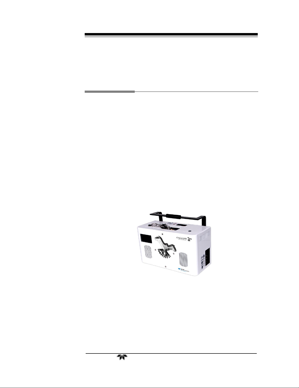
Introduction
Teledyne Analytical Instruments Falcon GC is an ultrafast
programmed temperature gas chromatograph consisting of:
• Heated split/splitless injection port including septum purge and
350°C maximum operating temperature.
• Inlet accepts gas or liquid syringe injections or optionally an
automated gas or liquid sample valve.
• One or two column modules, for simultaneous detection on two
individual column types, and one or two detector modules.
• Plug and play, precalibrated and individually programmed
temperature column modules, enabling dual simultaneous
analysis on the same sample, using different separation media
and temperature profiles for maximum selectivity.
• Touchscreen user interface panel.
The Falcon GC uses a Windows equipped PC in conjunction with
the Chromperfect software. The computer connection can be made
through a shared ethernet cable via TCP. The ethernet connection from
PC to GC can either be direct or through a network.
This manual presents the standard operating procedure for the
general use of the Falcon GC. You should have a general working
knowledge of the Chromperfect software, as well as the Falcon GC

Introduction Falcon GC
2 Teledyne Analytical Instruments
before using this guide. Since this is a general SOP, more specialized
methods such as ASTM D7798 or D3710 will require additional
instruction not present in this document. This guide does not include
instruction on the operation of the Palarus or Talon autosamplers.

Falcon GC
Preparatio
n
Teledyne Analytical Instruments 3
Preparation
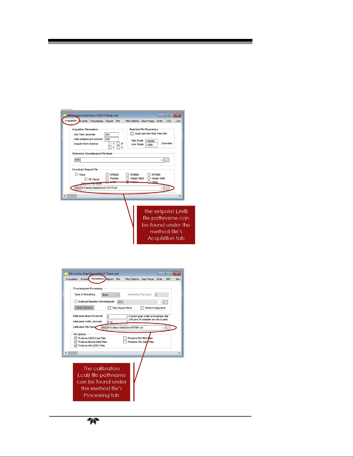
2.1 Chromperfect File Types
There are generally four key Chromperfect files that must work
together in order to ensure the effective operation of the Falcon GC.
Depending on the application, you may only need two or three of these
files. In some cases, even more files may be necessary. A method file
(.met) and a setpoint file (.mfl) are required for every application. Two
additional common file types are a calibration file (.cal) and a formatted
report file (.fmt). The folder destination for these files will vary from
user to user. Before getting started, check to make sure that the method
files have the correct pathnames defined for the files mentioned above.
This can be done by opening the method file in the File Editor Tab.
Click the “C” Chromperfect icon to open the Chromperfect banner and
then click on “Files”.
Here, click File→Open→Method and then click the “…” icon to
search for your method file.
Note: Depending on the current settings a pop-up window might
automatically open along with the File Editor program. If
that happens, just click Method from that window and then
click the “…” to select your method file.
Preparation Falcon GC
4 Teledyne Analytical Instruments
With the method file now open, click through the tabs to make sure
that all of your files are properly linked with the correct pathname.
Please note that your method may not require all these file types.
1. Click on Acquisition.
2. Click on Processing.
Falcon GC
Preparatio
n
Teledyne Analytical Instruments 5
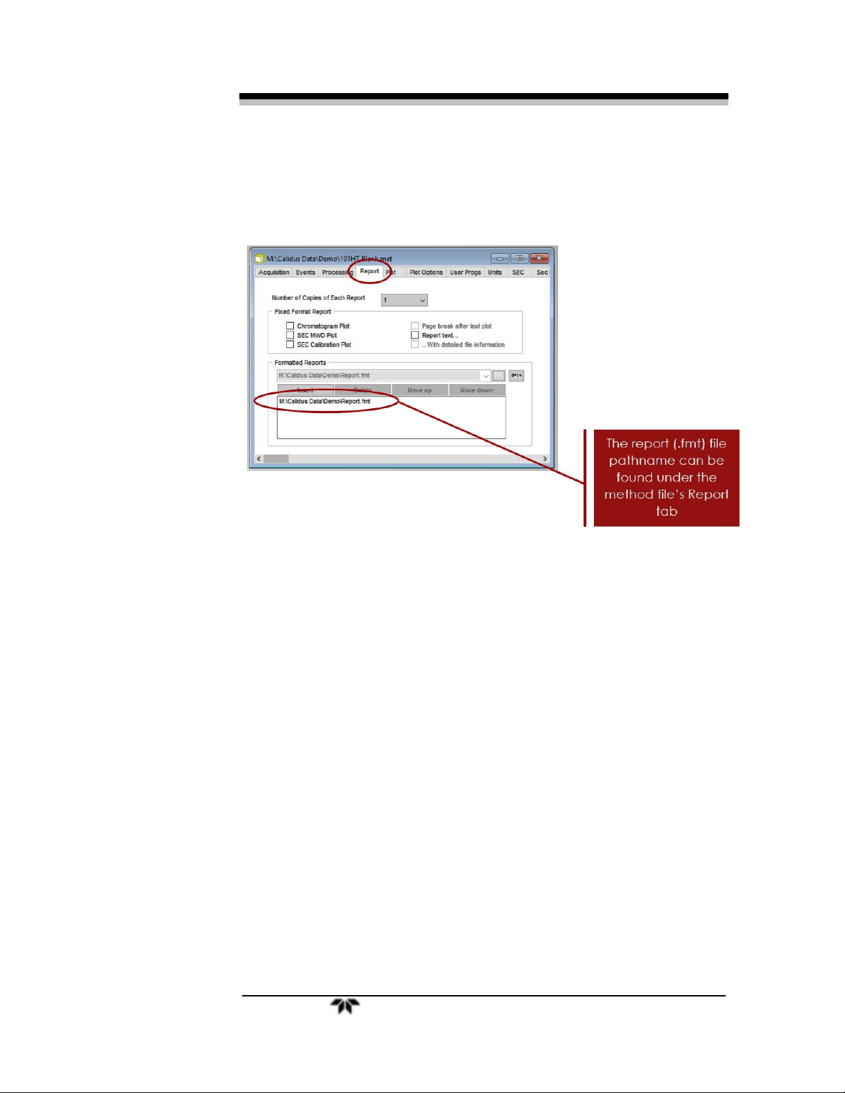
3. Click on Report.

Preparation Falcon GC
6 Teledyne Analytical Instruments
Blank Page

Falcon GC Installation
Teledyne Analytical Instruments 7
Installation
3.1 Preparation
Installation of the Falcon GC will require:
• Carrier Gas
o Typically H
2
, but may also be He or N2 in special
circumstances.
Note: Hydrogen and air must be supplied if the instrument is
equipped with an FID (Flame Ionization Detector) or FPD
(Flame Photometric Detector).
o All gases should be ultra high purity (99.9995% pure) or
better.
o Hydrogen carrier gas is typically supplied from a
hydrogen generator or gas cylinders.
o Carrier gas must be regulated down to 60-80 psi before
entering the GC.
• Zero Air
o Must be hydrocarbon and moisture free.
o Air is typically supplied from a zero air generator and
compressor or gas cylinders.
o Zero air must be regulated down to 80-90 psi before
entering the GC.
• Tubing, Nuts, and Ferrules
o Connections and tubing are supplied with the Falcon
Startup Kit.
o Gas connections to the GC require 1/16” stainless steel
tubing.
▪ 1/16” Valco internal nuts and ferrules for carrier
gas and FID fuel.
▪ 1/16” Swagelock external nut and ferrule for air
input.

Installation Falcon GC
8 Teledyne Analytical Instruments
▪ Falcon CS units require 1/8” tubing with a
Swagelock external nut and ferrule for air (1/8”
tubing is NOT included in the Falcon GC Startup
Kit).
▪ 1/16” Valco internal nuts and ferrules must also
be used for SAMPLE IN and SAMPLE OUT on
gas sample valves and liquid sample valves.
▪ Optional: 1/16” Swagelock external brass nuts
and ferrules for split vent and septum purge vent.
• Ethernet Cable
o Used for TCP/IP communication directly from a PC to
the GC or from the GC to LAN.
• Power Supply
o 100-240VAC Power Source, 50-60Hz, either 240W or
320W.
o Auxiliary valve heating or sample valves require
auxiliary power cables that must be plugged into the
control panel or utility panel, respectively.
o Appropriate power supplies and cables are always
supplied with the Falcon GC.
• Wrenches
o Wrenches are supplied with the Falcon Startup Kit.
o 1/4” for internal nuts.
o 5/16” for external nuts.
o 7/16” for external 1/8” nuts.
3.2 Setup/Installation
The Falcon GC is shipped with all the materials needed to install and
prepare the system for operation (Calibration Samples excluded).
Carefully unpack the unit and inspect it for damage. Immediately report
any damage or shortages to the shipping agent.
The Falcon GC is a general-purpose instrument and as such is
designed with (non-sealed) enclosures. The GC can be operated within
temperatures ranging from 32ºF to 100ºF but for best results ambient T
should be within 60-80ºF. In areas outside these temperatures, auxiliary
Falcon GC Installation
Teledyne Analytical Instruments 9
heating/cooling may need to be supplied. Avoid locating the instrument
where extreme vibration may occur.
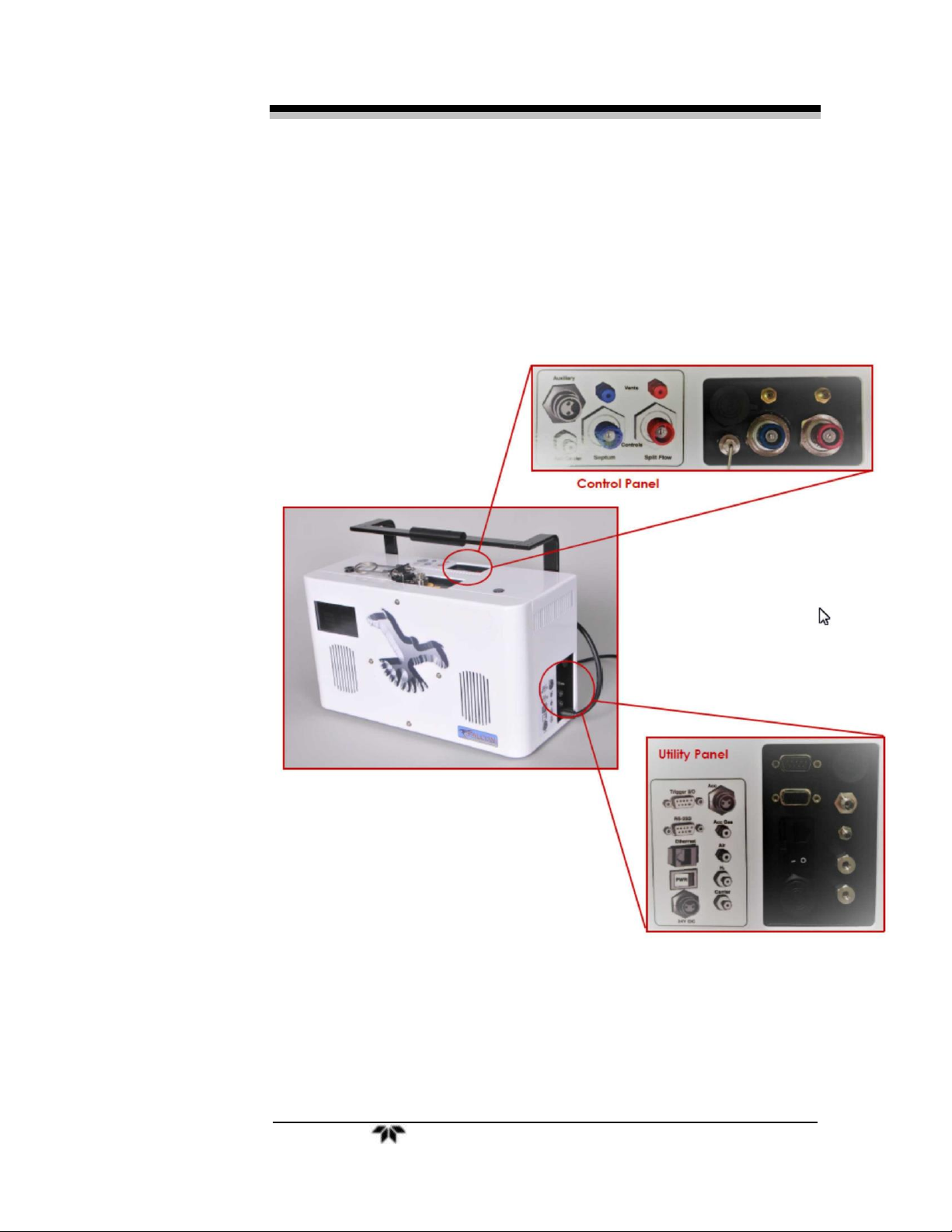
3.2.1 User Connections
Connect the appropriate tubing and cables according to the Control
Panel and Utility Panel diagrams located on the top of the instrument
and the right side of the instrument. See Figure 3-1 .
Figure 3-1: Instrument Connections
3.3 Configuring the Falcon GC
To properly use the Falcon GC you must connect the GC to a
Windows PC. This connection can be made through a shared ethernet
Installation Falcon GC
10 Teledyne Analytical Instruments
cable via TCP/IP. The ethernet connection from PC to GC can either be
direct or through a network.
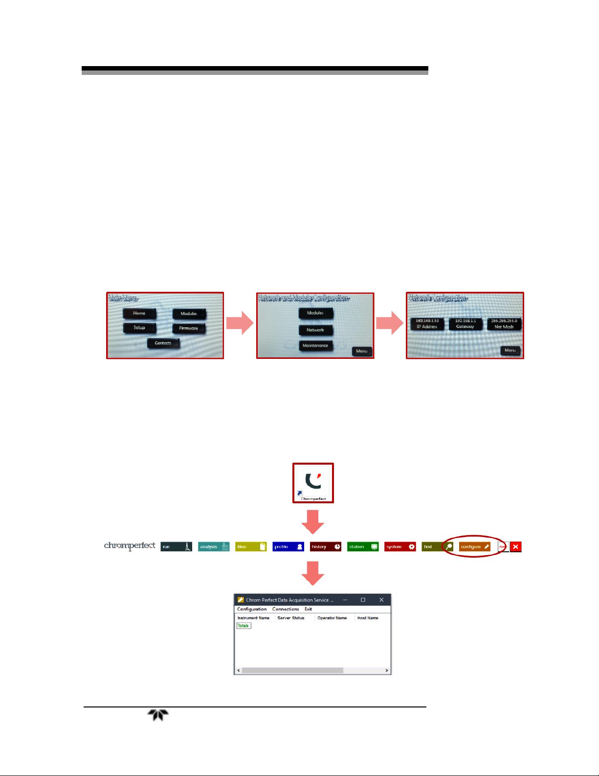
3.3.1 Setting the Falcon GC’s IP Address
To set the IP address, first, turn on the GC using the power toggle
switch on the Utility Panel.
On the Falcon touch screen press Menu→Setup→Network to access
the network options. From here you can view or change the GC’s IP
Address, Gateway, or Net Mask by pressing on their respective icons.
3.4 Configuring Chromperfect
1. Click on the “C” Chromperfect icon to open the Chromperfect
banner
2. Then click on Configure to open the configuration window.
Falcon GC Installation
Teledyne Analytical Instruments 11
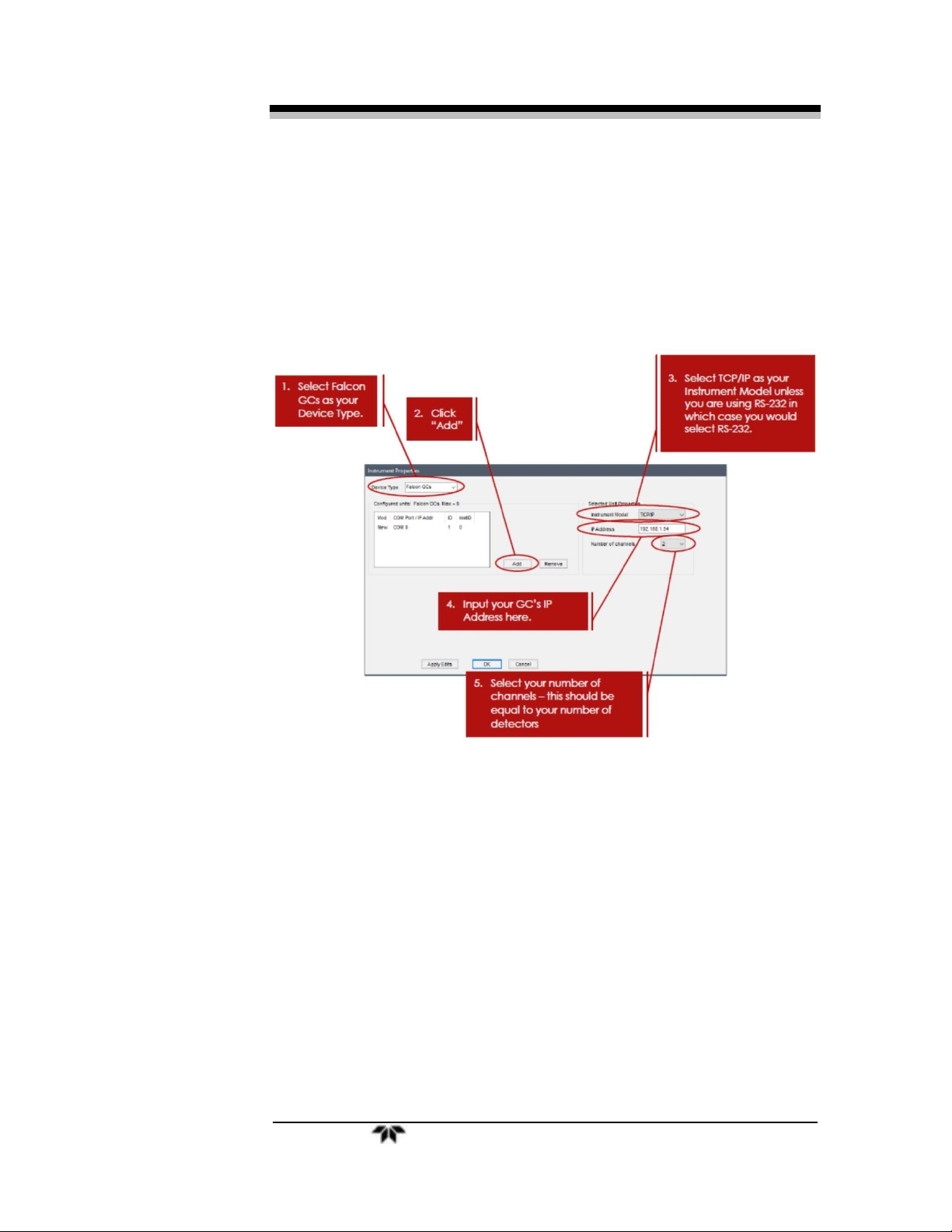
3. Click on Configuration at the top left of this new pop up
window. This will open the instrument properties pop-up
window.
4. After you have entered all the relevant information as seen
above, click on Apply Edits to apply your changes. Notice that
the small window where it says Mod and COM Port/IP Addr will
update with your current settings.
5. Click OK. A new pop-up window will appear with the title of
Instrument and Hardware Connections. Fill out the new pop-up
window as shown below:
 Loading...