

Falcon4™ 57M
Preliminary
Camera User’s Manual
FA-S0-57M16-00-R
sensors |
cameras
| frame grabbers | processors | software | vision solutions
03-032-20220-00
www.teledynedalsa.com

Preliminary
Notice
© 2015 Teledyne DALSA
All information provided in this manual is believed to be accurate and reliable. No
responsibility is assumed by Teledyne DALSA for its use. Teledyne DALSA reserves the right
to make changes to this infor m a tion without no tice. Reproduction of this manual in whole o r
in part, by any means, is prohibited without prior permission having been obtained from
Teledyne DALSA.
Microsoft and Windows are registered trademarks of Microsoft Corporation in the United
States and other countries. Windows, Windows 7, Windows 8 are trademarks of Microsoft
Corporation.
All other trademarks or intellectual property mentioned herein belong to their respective
owners.
Document Date: August 5, 2015
Document Number: 03-032-20220-00
Revision History
Revision Number Change Description Revision Date
00 Initial release of preliminary version to support
early consignment cameras.
About Teledyne DALSA
Teledyne DALSA is an international high performance semiconductor and electronics
company that designs, develops, manufactures, and markets digital imaging products and
solutions, in addition to providing wafer foundry s ervices.
Teledyne DALSA Digital Imaging offers the widest range of machine vision components in
the world. From industry-leading image sensors through powerful and sophisticated
cameras, frame grabbers, vision processors and software to easy-to-use vision appliances
and custom vision modules.
August 5, 2015

Contents
Preliminary
THE FALCON4 CAMERA OVERVIEW ................................................................ 3
CAMERA HIGHLIGHTS ....................................................................................... 3
Key Features ......................................................................................... 3
Programmability ..................................................................................... 3
Applications ........................................................................................... 3
Models .................................................................................................. 4
Camera Performance Specifications .......................................................... 4
CERTIFICATIONS & COMPLIANCE .......................................................................... 5
SHOCK AND VIBRATION .................................................................................... 5
SUPPORTED INDUSTRY STANDARDS ...................................................................... 6
GenICam™ ............................................................................................ 6
Camera Link HS ..................................................................................... 6
Camera Link HS Transmission Characteristics ............................................ 7
RESPONSIVITY ............................................................................................... 8
SENSOR COSMETIC SPECIFICATIONS ................................................................... 10
SENSOR BLOCK DIAGRAM AND PIXEL READOUT ...................................................... 11
CAMERA SETUP ............................................................................................ 12
SYSTEM PRECAUTIONS AND CLEANING ................................................................. 12
Precautions ......................................................................................... 12
Cleaning the Device .............................................................................. 12
Electrostatic Discharge and the CMOS Sensor .......................................... 12
SOFTWARE AND HARDWARE SETUP ............................................................ 13
RECOMMENDED SYSTEM REQUIREMENTS ............................................................... 13
SETUP STEPS: OVERVIEW ................................................................................ 13
Step 1: Install and Configure Frame Grabber and Software ........................ 13
Step 2: Connect Camera Link and Power Cables ....................................... 13
Power Connector .................................................................................. 14
Step 3: Establish Communication with the Camera ................................... 18
USING CAMEXPERT ...................................................................................... 21
CamExpert Panes ................................................................................. 21
Creating a Camera Configuration File in the Host ...................................... 23
CAMERA OPERATION ................................................................................... 24
Factory Settings ................................................................................... 24
CHECK CAMERA AND SENSOR INFORMATION .......................................................... 24
Verify Temperature ............................................................................... 24
SAVING AND RESTORING CAMERA SETTINGS ......................................................... 25
ACQUISITION AND TRANSFER CONTROL FEATURES ................................................... 26
TEST PATTERNS ............................................................................................ 27
GAIN AND BLACK LEVEL CONTROL DETAILS ........................................................... 29
EXPOSURE CONTROLS .................................................................................... 30
Exposure Time ..................................................................................... 32
Trigger Modes ...................................................................................... 32
Internal Frame Rate ............................................................................. 33
Falcon 4 Camera User's Manual Contents • 1

I/O Block Diagram ................................................................................ 33
Preliminary
Opto-Coupled Inputs ............................................................................ 33
Opto-Coupled Outputs .......................................................................... 34
FLAT FIELD CORRECTION AND DEFECTIVE PIXEL DETECTION OVERVIEW ......................... 35
Correction Function Bloc k Diagram ......................................................... 35
Flat Field Correcti on Algorithm Description ............................................... 36
An important note on window blemishes ................................................. 37
How to do an FFC Setup in the C a m era ................................................... 37
Matching gain and offset values on multiple cameras ................................ 39
Defective Pixel Detection and Replacement .............................................. 39
Static Pixel Replacement ....................................................................... 39
File Access via the CamExpert Tool ......................................................... 40
TECHNICAL SPECIFICATIONS ...................................................................... 41
MECHANICALS.............................................................................................. 41
APPENDIX E: EMC DECLARATION OF CONFORMITY .................................................. 42
TBD ......................................................................................................... 42
APPENDIX A: GENICAM COMMANDS ............................................................ 43
CAMERA INFORMATION CATEGORY ...................................................................... 43
Camera Information Feature Descriptions ................................................ 43
ACQUISITION AND TRANSFER CONTROL CATEGORY .................................................. 45
Acquisition and Transfer Control Feature Descriptions ............................... 45
SENSOR CONTROL CATEGORY ........................................................................... 45
Sensor Control Feature Descriptions ....................................................... 45
I / O CONTROL CATEGORY ............................................................................... 47
I/O Controls Feature Descriptions ........................................................... 47
ADVANCED PROCESSING CONTROL CATEGORY ........................................................ 50
Advanced Processing Control Feature Descriptions .................................... 50
IMAGE FORMAT CONTROLS CATEGORY ................................................................. 54
CLHS LINK TRANSPORT LAYER CATEGORY ............................................................ 56
Camera Link Transport Layer Feature Description ..................................... 56
FILE ACCESS CONTROL CATEGORY ..................................................................... 57
APPENDIX B: CAMERA, FRAME GRABBER COMMUNICATION ........................ 59
SETTING UP COMMUNICA TION BETWEEN THE CAMERA AN D THE FRAME GRABBER ............... 59
APPENDIX C: CLEANING THE SENSOR WINDOW .......................................... 60
Recommended Equipment ..................................................................... 60
Procedure ............................................................................................ 60
APPENDIX D: INTERNAL FLAT FIELD CALIBRATION ALGORITHMS .............. 61
Offset (FPN) Calibration ........................................................................ 61
Gain (PRNU) Calibration ........................................................................ 61
APPENDIX E: FILE FORMAT ......................................................................... 63
LUT FILE FORMAT ......................................................................................... 63
FFC FILE FORMAT ......................................................................................... 64
CONTACT INFORMA TION ............................................................................. 66
SALES INFORMATION...................................................................................... 66
TECHNICAL SUPPORT...................................................................................... 66
2 • Contents Falcon 4 Camera User's Manual

The Falcon4 Camera Overview
Preliminary
Camera Highlights
Teledyne DALSA’s new generation of monochrome area scan cameras—the
Falcon4 57M—incorporate very large resolutions and faster frame rates, enabling high
speed image capture with superb spatial resolution and improved image quality. Global shuttering
and correlated double sampling ensure smear free and low noise images. These features make the
Falcon4 camera the best choice for applications where throughput, resolution and high pixel
capacity matter most.
In
side the Falcon4 camera is our leading-edge CMOS sensor, which enables high speeds at
very large resolutions. This new production of CMOS sensors builds upon the performance of the
Falcon2 and Falcon3 cameras and improves on image quality.
Th
e Falcon4 cameras are compliant with GenICam™ and CLHS™ specifications—delivering
12 or 16 bits of data. In addition, the M95 thread opening allows for your choice of lens.
Key Features
• Exposure control
• Faster frame rates through windowing
• Good NIR response
• Built-in FPN and PRNU correction
• GenICam compliant
• CLHS interface
Programmability
• Adjustable analog / digital gain and offset
• 12 and 16 bit selectable output
• Adjustable integration time and frame rate
• Test patterns and camera diagnostics
• Horizontal and vertical ROI
Applications
• Semiconductor wafer inspection
• Semiconductor package inspection
• Electronics manufacturing
o 3D solder paste inspection
o Automated Optical Inspection (AOI)
• 3D imaging—Laser profiling
The Falcon4 Camera Overview Falcon 4 Camera User's Manual • 3

Models
Preliminary
The camera is available in the following configuratio ns.
Table 1: Camera Models Overview
Model Number Description
FA-S0-57M16-00-R 57M pixel monochrome, Camera Link HS.
Table 2: Software
Software Product Number / Version Number
Camera firmware Embedded within camera
GenICam™ support (XML camera description file) Embedded within camera
Recommended: Sapera LT, including CamExpert GUI application and
GenICam for Camera Link imaging driver.
Version 7.50 or later
Camera Performance Specifications
Table 3: Camera Performance Specifications
Specifications Performance
Resolution 7168(H) x 8064 (V)
Pixel Rate 1.37 Gpixel / s
Max. Frame Rate 16 fps
Pixel Size 6 µm x 6 µm
Bit Depth 12 bits, Camera Link HS
Exposure Time 100 µs minimum
Dynamic Range Mono** 59 dB (monochrome) (Global Shutter)
65 dB (monochrome) (Rolling Shutter)
Operating Temp 0 °C to 50 °C, front plate temperature
Connectors and Mechanicals
Size 100 mm (H) x 100 mm (W) x 80.5 mm (D)
Mass < 1 kg
Data Interface CLHS—single C2 7M1, CX4 connector
Power Connector Hirose 12-pin circular
Power Supply + 12 V to + 24 V DC
Power Dissipation < 35 W
Lens Mount M95 x 1
Sensor Alignment ± 100 µm in X-Y directions
Compliance
Regulatory Compliance CE and RoHS
Mono Operating Ranges Units Notes
Random Noise DN rms 4.6(GS), 2.3(RS) Typical, FFC disabled
Responsivity DN/(nJ/cm2) See graph Figure 1.
DC Offset DN FFC enabled
4 • Falcon 4 Camera User's Manual The Falcon4 Camera Overview

Preliminary
Mono Operating Ranges Units Notes
Antiblooming >600 x Saturation
FPN DN rms 7 Typical, FFC enabled
PRNU DN rms 10 Typical, FFC enabled
Integral non-linearity DN 3% From 10-90% of
camera saturation
*DN = digital number
Test Conditions:
• TBD
Table 4: Frame Rates, Aspect Ratio, and Resolution Comparison
Resolution Aspect
Ratio
57M 0.89 7168 8064 16@12bit 2 to 8
Maximum
Column
Maximum
Rows
No summing
(Max)
Summing (Max)
Certifications & Compliance
Compliance
EN 55011, CISPR 11, EN 55022, CISPR 22, FCC Part 15, and ICES-003 Class A Emissions Requirements.
EN 55024, and EN 61326-1 Immunity to Disturbance.
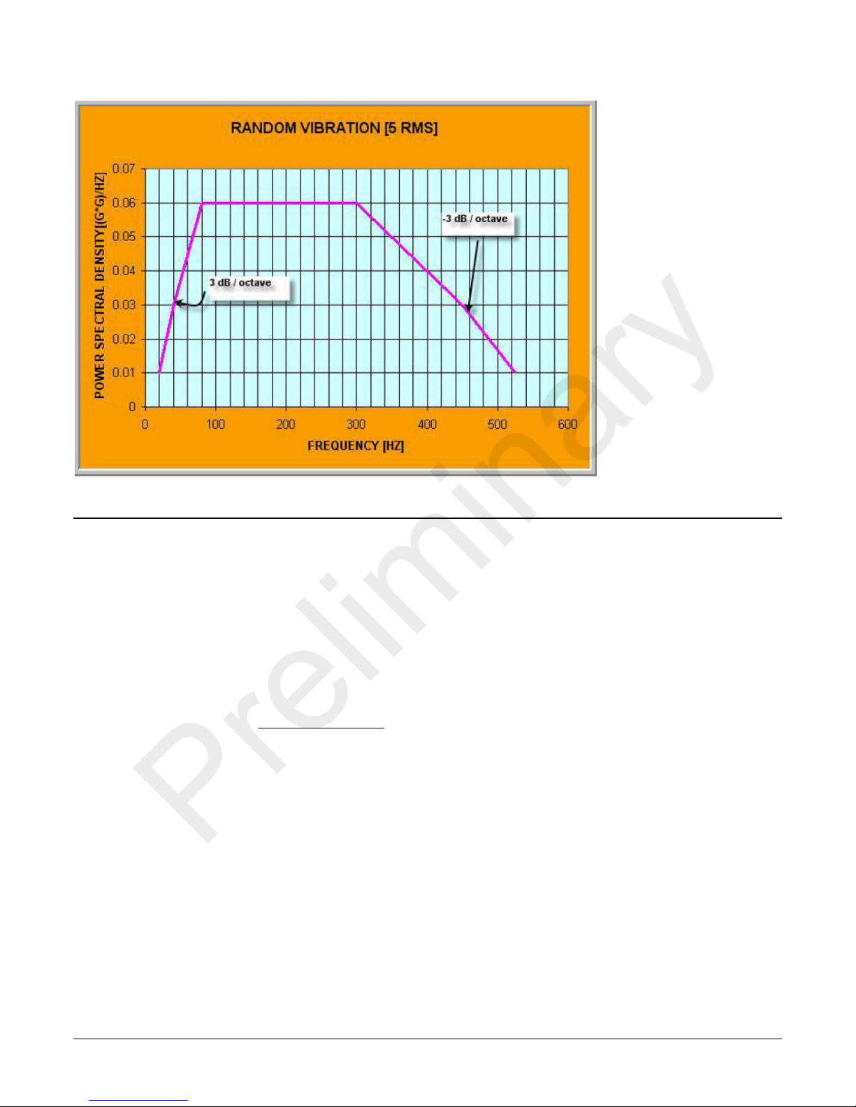
Shock and Vibration
The cameras meet or exceed the following specifications:
• Random vibration per MIL-STD-810F at 25 G
• Shock testing 75 G peak acceleration per MIL-STD-810F
2
/HZ [Power Spectral Density] or 5 RMS
The Falcon4 Camera Overview Falcon 4 Camera User's Manual • 5
Preliminary
Supported Industry Standards
GenICam™
The camera is GenICam compliant and implements a superset of the GenICam Standard Features
Naming Convention specification V1.5.
This description takes the fo rm of an XML device des cription file using the syntax defined by the
GenApi module of the GenICam specification. The camera uses the GenICam Generic Control
Protocol (GenCP V1.0) to communicate over the Camera Link HS command lane.
For more information see www.genicam.org
Camera Link HS
The camera is Camera Link HS version 1.0 compliant. Camera Link HS is the next generation of
high performanc e communications standards and is used where a digital industr ial camera
interfaces with single or multiple frame grabbers with data rates exce eding those supported by
Camera Link. The camera includes a single Camera Link HS compatible connector, capable of
supporting data rates up to 2.1 Gbytes per second. The connector can also interface with standard
‘CX4 Active Optical Cable’ fiber modules where very long data transmission is required—up to 300
meters.
.
6 • Falcon 4 Camera User's Manual The Falcon4 Camera Overview
RXC
TXC
TX1
TX2
TX3
TX4
TX5
TX6
TXC
RXC
RX1
RX2
RX3
RX4
RX5
RX6
Data Lane 6
Data Lane 0
Command
Channel
Video
Channel
Link
Camera
(C2,7M1)
Frame Grabber
(C2,7M1)
Preliminary
Figure 1. Single CLHS Connector Configuration
The command channel is used by the frame grabber to send command, configuration, and
programming data to the camera and to receive comm a nd responses, status, and image data from
the camera.
The designation C2, 7M1 defines the use of a SFF-8470 connector (C2) and up to 7 lanes of data
with 1 command channel using M-Protocol (8b/10b) at the default spee d of 3.125 Gb/sec.
When using a CX4 Active Optical Cable fiber module, only the command channel and data lanes 0,
1, 2 and 3 (C2, 4M1) will be available, with an associated reduction in bandwidth. Use two fiber
modules to retain the full performance of the camera.
A feature of CLHS is that the initialization of the frame grabber automatically starts a discovery
process that will identify the lane configuration of the camera. This process is transparent to the
user and requires no action by the user to correctly configure the link.
Camera Link HS Transmission Characteristics
The camera data distribution supports 1 cable with single ROI capability. The single ROI is
customer entered and transmitted across all seven data lanes. There is a minimum of 96 pixels per
data lane used.
CLHS limits the start and stop location of the ROI to a multiples of 32 pixels. The maximum line
rate is limited by the sensor when not limited by the CLHS cable or by the PCIe transfer. The sensor
is limited to a 125 kHz maximum line rate.
The CLHS cable has approximately 2.1 GByte / sec bandwidth for seven lanes. The XTIUM frame
grabber has about 1.6 GByte / sec acros s the PCIe bus.
The Frame Grabber is able to store rows in order to perform a “burst-type” operation. CLHS packs
the bits, while the frame grabber unpacks 12 bit data into 16 bit data across the PC Ie bus.
The Falcon4 Camera Overview Falcon 4 Camera User's Manual • 7
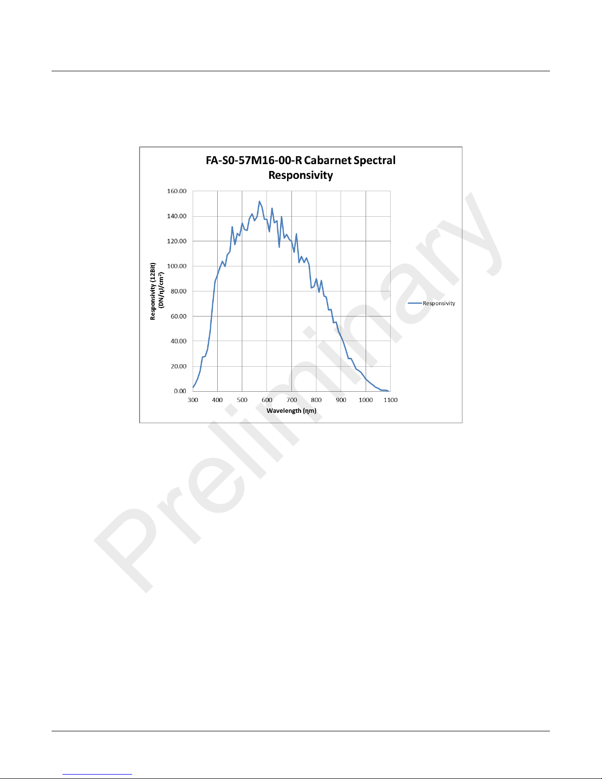
Responsivity
Preliminary
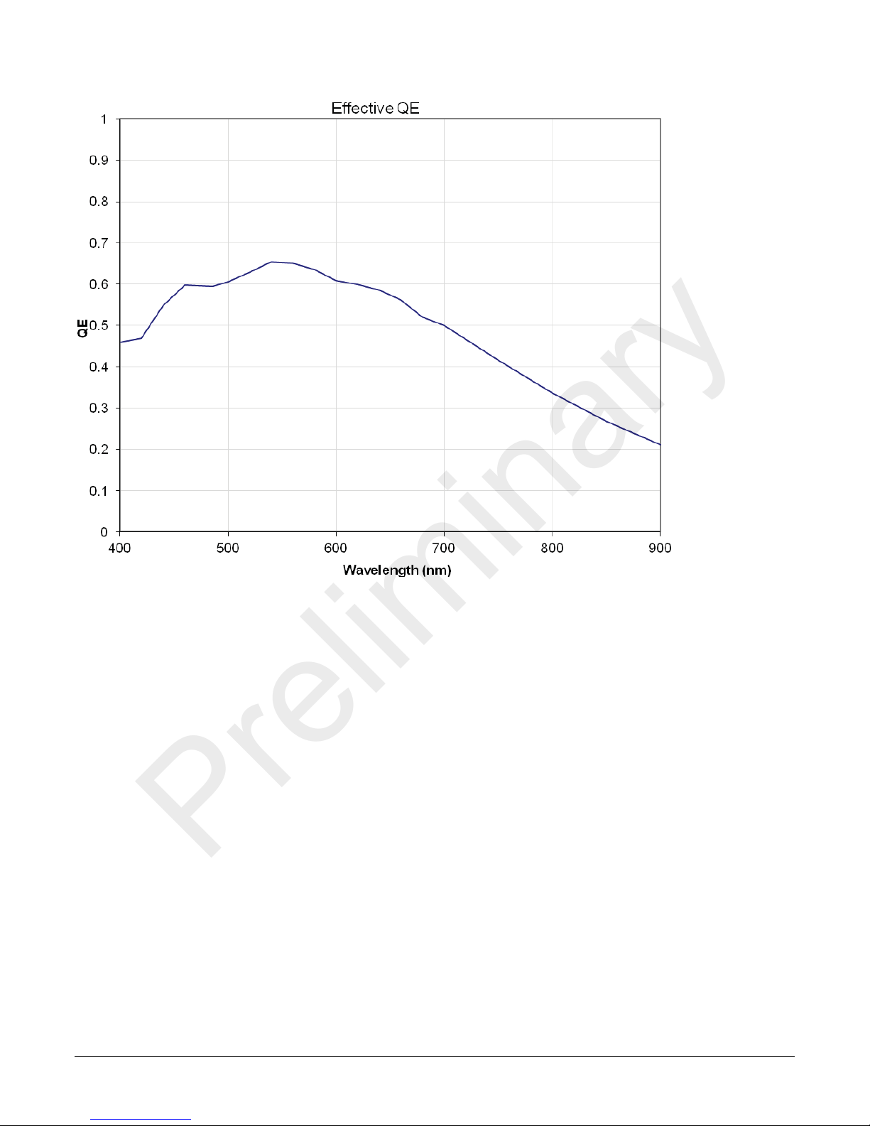
The responsivity graph de scribes the camera’s response to different wavelengths of light (excluding
lens and light source characteristics).
Figure 2: Falcon4 Monochrome 57M S p ectral Responsivity
8 • Falcon 4 Camera User's Manual The Falcon4 Camera Overview
Preliminary
Figure 3: Falcon4 Monochrome 57M Effective QE
The Falcon4 Camera Overview Falcon 4 Camera User's Manual • 9

Sensor Cosmetic Specifications
Tolerated Count
#
50
Tolerated Count
# - 0
pixel outside
single column.
Column Defect Count
# 0
20 contiguous pixel defects along a
single row.
Row Defect Count
# 0
Preliminary
The following table lists the current cosmetic specifications for the Teledyne DALSA sensor used in
the Falcon4 series.
Feature /
Specification
Unit
MIN TYP
MAX
Notes
Dark Pixel Definition -
absolute output level
Dark Pixel Count # 50
Light Pixel Definition -
deviates from frame
average
Average Frame
Output Level
Detection Threshold - Groups of
Tolerated Count # 7 Based on estimation algorithm
Detection Threshold Groups of
Glass Spot Defect
Definition
DN > 500 4 frame average
% ± 30 4 frame average image
for scene & dark correction
% SAT 40 50 60 Illuminated with diffused
light source
combined dark and light pixel
dark and light pixels
Combined dark and light pixel
dark and light pixels
defects/kernel 8 / 3x3 8 / 3x3 Illuminated with aperture
defects
defects
(collimated) light source
Detection Threshold % of average ± 8 4 frame average - any
Tolerated Count # 1 1 spot of 9 pixels allowed. No limit
Column Defect
Definition
Row Defect Definition defects/kernel > 20 /Xx1 A horizontal grouping of more than
10 • Falcon 4 Camera User's Manual The Falcon4 Camera Overview
defects/kernel > 20 / 1xY A vertical grouping of more than 20
± 8% of average
on spots below 9 pixels
contiguous pixel defects along a
Table 5: Sensor Cosm etic Specifications
Preliminary
Definition of Blemishes
• Dark pixel defect: Pixel whose signal, in dark, exceeds 500 DN.
• Light pixel defect: Pixel whose signal, at nominal light (illumination a t 50 % of the linear
range), deviates more than ±24 % from its neighboring pixels.
• Cluster defect: A grouping of at most 2 to 5 pixel defects within a sub-area of 3*3 pixels.
• Glass Spot defect: A grouping of 9 pixel defects within a sub-area of 3*3 pixels.
• Column Defect: A vertical grouping of more than 20 contiguous pixel defects along a single
column. Must be a minimum of 5 good columns between defective columns. If column defect
count is >0 then row defect quantity must = 0. Column defect concealment will be applied
for defective columns.
• Row Defect: A hor izontal grouping of more than 20 contiguous pixel defects along a single
row. Must be a minimum of 5 good rows between defective rows. If row defect count is > 0
then column defect quantity must = 0. Ro w defect concealment will be applied for defective
rows.
• Test conditions Temperature: 40 °C.
• Integration Time: 12 ms.
Sensor Block Diagram and Pixel Readout
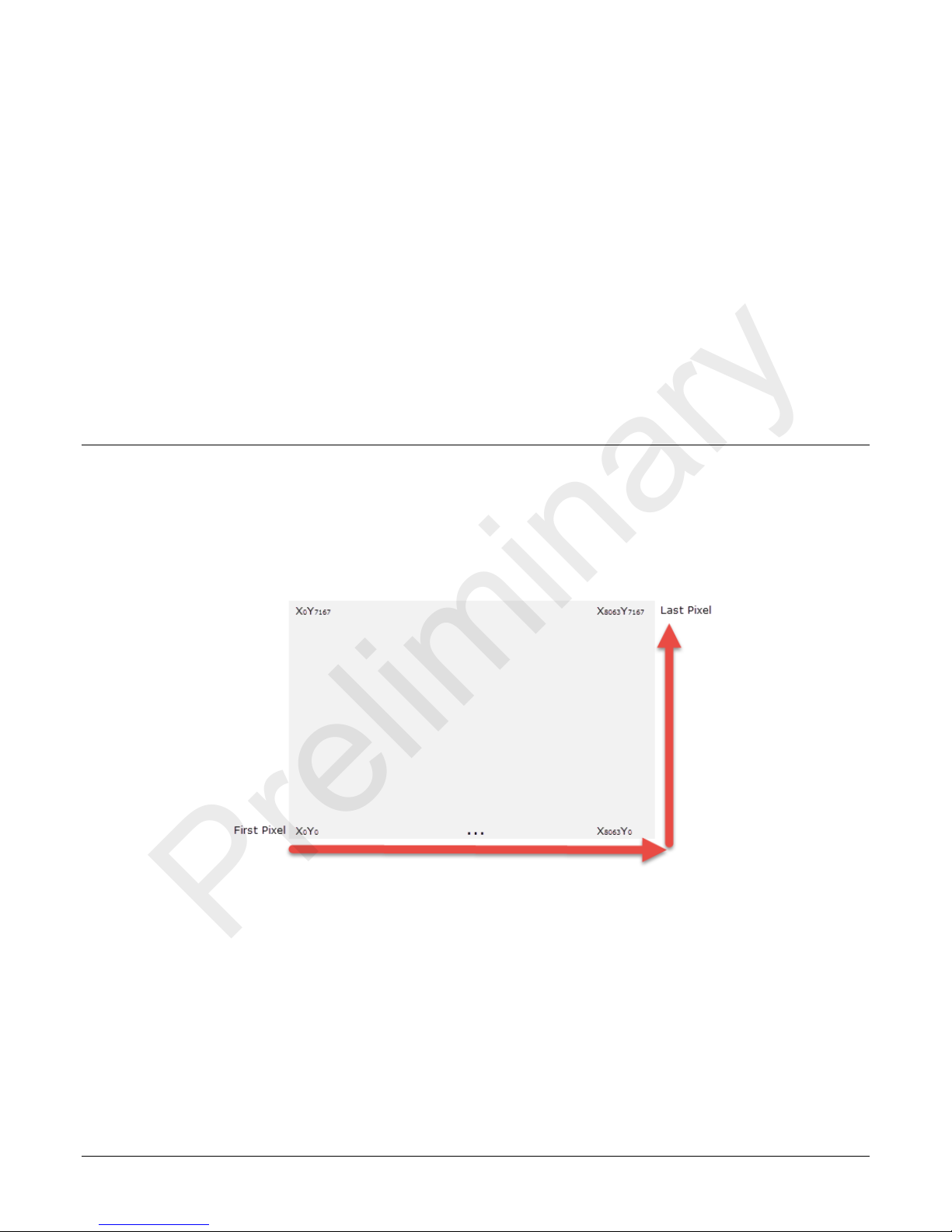
Pixels are read from left to right, top to bottom. The data for each line is transferred from the
sensor to 7 CLHS data lanes. CLHS is a packet-based protocol therefore the concept of taps or tap
geometry does not apply; the frame grabber reconstructs the images based on the information
contained in the packet, regardless of which data lane is used for the transfer.
Figure 4: Pixel Readout of the Falcon 4 c amera.
Notes:
• As viewed looking at the front of the camera without a lens. (The Teledyne DALSA logo on
the side of the case will be right-side up.)
The Falcon4 Camera Overview Falcon 4 Camera User's Manual • 11

Camera Setup
Preliminary
System Precautions and Cleaning
Precautions
Read these precautions and this manual before using the camera.
Do not open the housing of the came ra. The warra nt y is voided if the housing is
opened.
• Confirm that the camera’ s packaging is undamaged before opening it. If the packaging is
damaged please contact the related logistics personnel.
• Keep the camera’s front plate temperature in a range of 0 °C to 50 °C during operation. The
camera has the ability to measure its internal temperature. Use this feature to record the
internal temperature of the camera when it is mounted in your system and operating under
the worst case conditions. The camera will stop outputting data if its internal temperature
reaches 70 °C. Refer to section the Verify Temperature for more information on the
‘Temperature’ feature.
• Do not operate the camera in the vicinity of strong electromagnetic fields. In addition, avoid
electrostatic charging, violent vibration, and excess moisture.
• Though this camera supports hot plugging, it is recommended that you power down and
disconnect power to the camera before you add or replace system components.
Cleaning the D e vice
To clean the device, avoid electrostatic charging by using a dry, clean absorbent cotton cloth
dampened with a small quantity of pure alcohol. Do not use methylated alcohol.
To clean the surface of the camera housing, use a soft, dry cloth. To remove severe stains use a
soft cloth dampened with a small quantity of neutral detergent and then wipe dry. Do not use
volatile solvents such as benzene and thinner s, as they can damage the surface finish.
Electrostatic Discharge and the CMOS Sensor
Image sensors and the camera bodies housing are susceptible to damage from electrostatic
discharge (ESD). Electrostatic charge introduced to the sensor window surface can induce charge
buildup on the underside of the window. If this occurs, the charge normally dissipates within 24
hours and the sensor returns to normal operation.
12 • Falcon 4 Camera User's Manual Camera Setup

increased emission or decreased immunity and performance of the camera.
Preliminary
Software and Hardware Setup
Recommended System Requirements
To achieve best system performance, the following minimum requirements are recommended:
• High bandwidth frame grabber. For example, Teledyne DALSA Xtium or Xcelera CLHS series
frame grabbers: http://www.teledynedalsa.com/imaging/products/fg/#digital-cameralink
• Operating systems: Refer to frame grabber documentation for supported platforms.
Setup Steps: Overview
Take the following steps in order to setup and run your camera system. They are described briefly
below and in more detail in the sections that follow.
1. Install and Configure Frame Grabber and Software
.
2. Connect Camera Link and Power Cables
3. Establish communication with the ca m era
Step 1: Install and Configure Frame Grabber and Software
Teledyne DALSA recommends its Xtium or Xcelera CLHS series frame grabbers or equivalent.
Follow the manufacturer’s installation instructions.
For additional information on configuring frame gra bbers, see .
A GenICam™ compliant XML device description file is embedded within the camera firmware
allowing GenICam™ compliant ap plication to kno w the camera’s capabilities immediately after
connection.
Installing Sapera LT gives you access to the CamExpert GUI, a GenICa m™ compliant application.
Sapera LT is available free of charge for download from the Teledyne Dalsa
website.
Step 2: Connect Camera Link and Power Cables
The camera uses a Camera Link HS SFF-8470 (CX4) cable and a Hirose connector for power and IO
connections.
• Connect the required Camera Link HS cable from the camera to the frame grabber installed
on the computer.
• Connect a power c a ble from the camera to a power supply that can provide a constant
voltage from +12 VDC to +24VDC.
Note: the use of cables types and lengths other than those specified may result in
Software and Hardware Setup Falcon 4 Camera User's Manual • 13
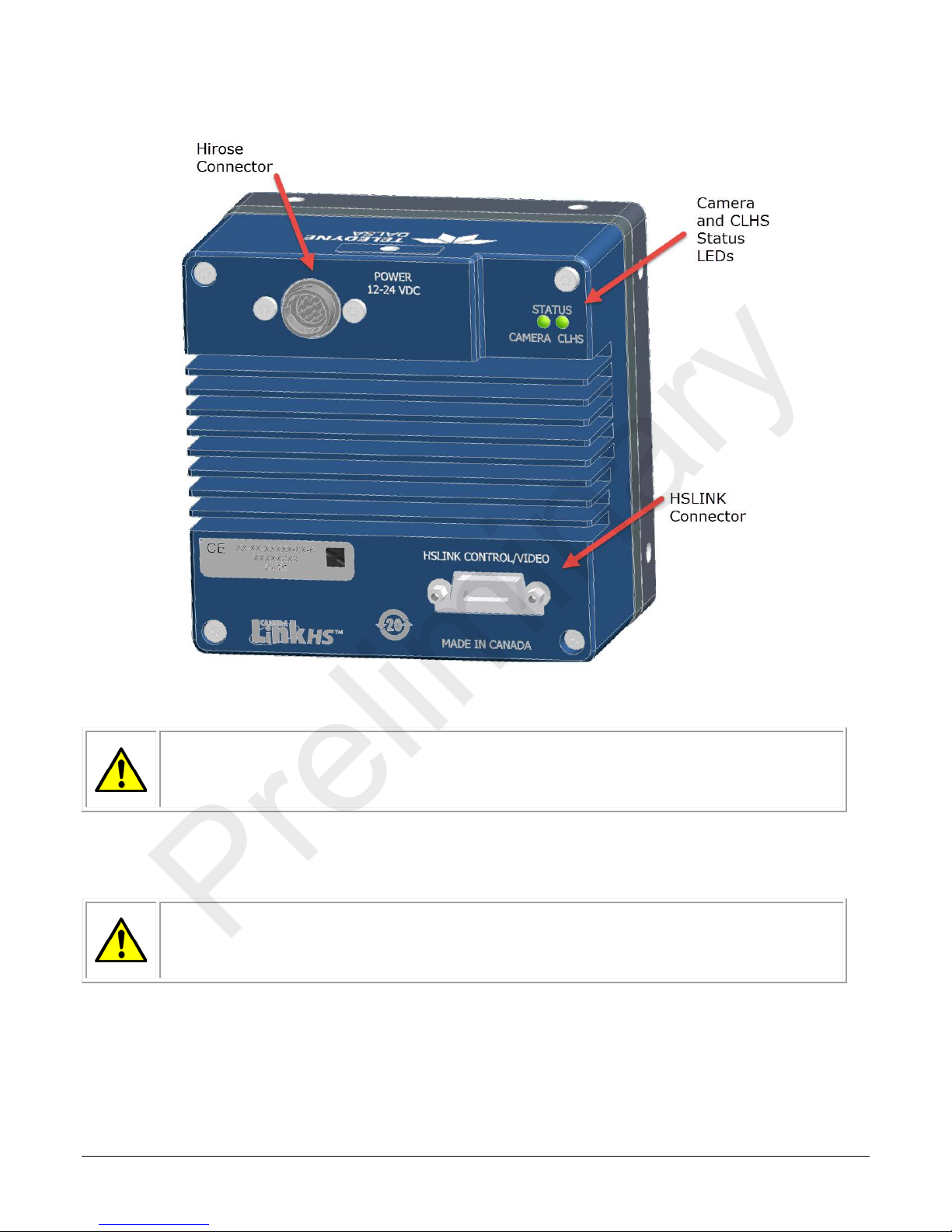
Figure 5: Input and Output, trigger, and Power Connectors
WARNING! Grounding Instructions
computer chassis, before performing handling the camera hardware.
WARNING: It is extremely important that yo u a pply the a pp ropriate voltages to
the camera, test all power supplies.
Preliminary
Static electricity can damage electronic components. It’s critical that you discharge
any static electrical charge by to uching a grounded surface, suc h a s the metal
Power Connector
your camera. Incorrect voltages may damage the camera. Input voltage
requirement: +12 VDC to +24 VDC (± 5 %), 2 Amps. Before connecting power to
14 • Falcon 4 Camera User's Manual Software and Hardware Setup
1 2 3
4 5 6 7 8
9
10
11
12
Preliminary
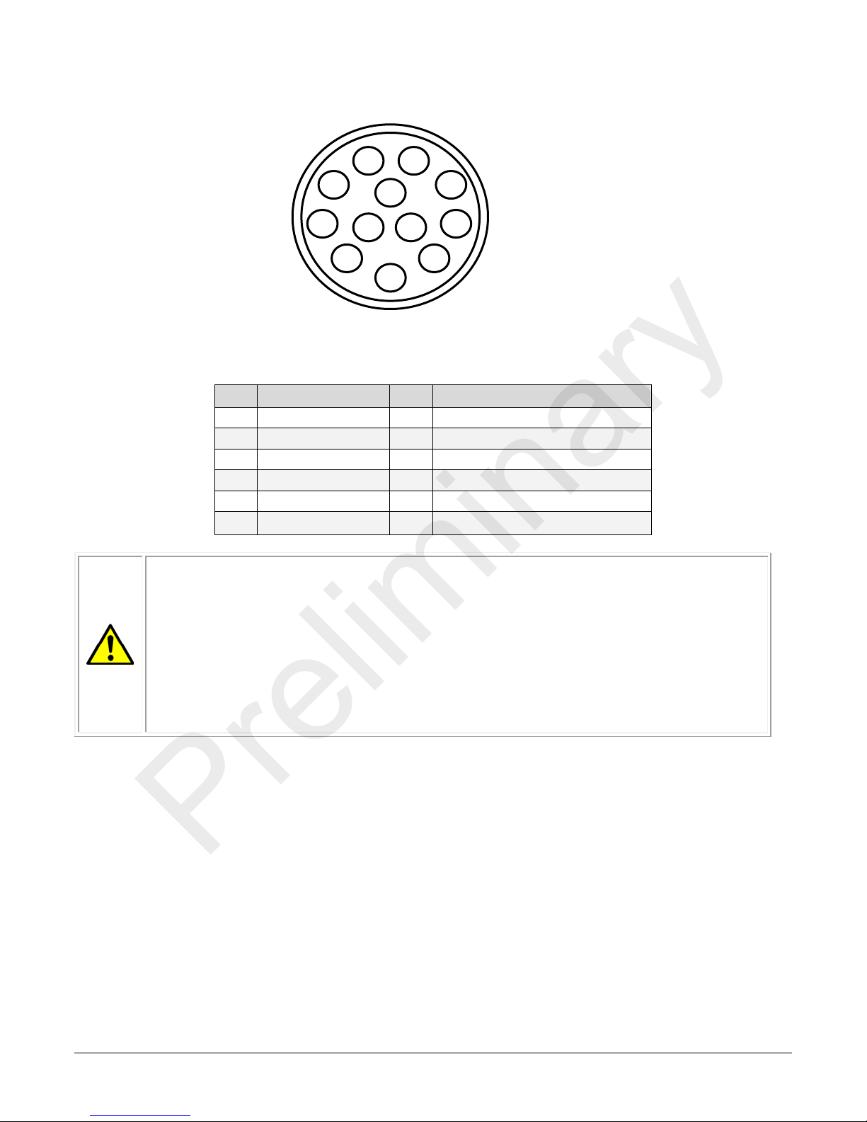
Figure 6: 12-pin Hirose Circular Male Power Plug—Power Connector
Table 6. Power Plug Pinout
Pin Description Pin Description
1 GND 7 OUT2+
2 +12 V to +24 V DC 8 OUT23 OUT1- 9 NC
4 OUT1+ 10 NC
5 IN1-/Trigger 11 IN2+/Trigger
6 IN1+/Trigger 12 IN2-/Trigger
WARNING: When setting up the camera’s power supplies follow these guidelines:
• Apply the appropriate voltages.
• Protect the camera with a 3 amp slow-blow fuse between the power supply
and the camera.
Camera Link Data Connector
The camera uses a Camera Link HS SFF-8470 (CX4) cable.
Input Signals, Camera Link
The camera accepts control inputs through the Camera Link HS SFF-8470(CX4) connector.
The camera ships (factory setting) in internal sync, and internally triggered integration.
Frame Start Trigger (EXSYNC)
The EXSYNC signal tells the camera when to integrate and readout the image. It can be either an
internally generated signal by the camera, or it can be supplied externally by a CLHS Pulse
Message, GPIO, and software command.
• Do not use the shield on a multi-conductor cable for ground.
• Keep leads as short as possible in order to reduce voltage drop.
• Use high-quality linear s upplies in order to minimize noise.
Note: If your power supply does not meet these requirements, then the camera
performance specifications are not guaranteed.
Software and Hardware Setup Falcon 4 Camera User's Manual • 15

LED Indicators
Off
No power or hardware malfunction.
maintained but ima ging is disabled.
up to 90 seconds.
Blue fast blinking
Firmware upgrade, file transfer.
During power up this indicates that the c amera is waiting for a c om mand.
Green solid
Free-running acqu isition.
Green slow blinking
Calibration in progr ess.
blinking
Off
No power or hardware malfunction.
Orange solid
The frame grabber is holding th is device in reset preventing any comm unication.
Orange slow blinking
The device is establishing communica tion and the camera is initializing.
up to 90 seconds.Ca
maintained but imaging is disabled.
Red fast blinking
Camera has CLHS link error.
Green solid
Link established and data transfer may take place.
Green fast blinking
Camera is waitin g for trigger.
Green slow blinking
Looking for Link.
Status
LED
CLHS
Status
LED
Initial power up
Camera initializing
(slow blinking)
Link established
Camera waiting for trigger
(fast blinking)
Initial power up
Camera initializing
(slow blinking)
Camera in free-running mode
Waiting for command
Preliminary
The camera is equipped with 2 LEDs on the back to display the operational status of the camera.
The tables below summarizes the operating states of the camera and the corresponding LED states.
When more than one condition is active, the LED indicates the condition with the highest priority.
Color of Camera
Status LED
Red slow blinking Camera in temporary s hutdown (e.g. temp er ature). The communication channel is
Red solid Fatal error state. Device is not functional. During power up the LED state is red for
Blue slow blinking Camera waiting for warm up to complete (Camera initialization)
Blue solid Upgrading inter nal firmware, when a c quisition is disabled. This happens when
changing a camera feature that effects the image output (e.g. aoi, bit depth, etc.).
Meaning
Orange slow
Color of CLHS Status
LED
Red solid Fatal error state. Dev ice is not functiona l. During power up the LED state is r ed for
Red slow blinking Camera in tempora r y shutdown (e.g. temperature). Th e communication ch a nnel is
Camera initializing.
Meaning
LED States on Power Up
The following LED sequence occurs when the Falcon 4 is powered up connected to a CLHS frame
grabber.
16 • Falcon 4 Camera User's Manual Software and Hardware Setup

Preliminary
Software and Hardware Setup Falcon 4 Camera User's Manual • 17

Step 3: Establish Communication with the Camera
Preliminary
To establish communication with the camera:
1. Power on the camera
2. Connect to the frame grabber
3. Connect to the camera
Power on the camera
Turn on the camera’s power supply. You may have to wait up to 60 seconds for the camera to
warm up and prepare itself for operation. The camera must boot fully before it will be recognized by
the GenCP compliant application; the CLHS LED will blink green, and camera LED will turn blue if
using a TeledyneDalsa frame grabber.
Initialize the frame grabber
• Start Sapera CamExpert (or an equivalent GenCP-compliant interface) by double-clicking
the desktop icon created during the software installation.
• CamExpert will search for Sapera devices installed on your system. In the Devices list area
on the left side of the GUI, the connected frame grabber will be shown.
• Select the frame grabber device by clicking on its name.
Note: The first time you set up the camera you will need to establish a communication link between
the camera and frame grabber. Instructions are available in Appendix B: Camera, Frame Grabber
Communication.
Initialize communication w ith the ca m e ra
• Start a new Sapera CamExpert application (or equivalent Camera Link compliant interface)
by double-clicking the desktop icon crea ted during the software installation.
• CamExpert will search for Sapera devices installed on your system. In the Devices list area
on the left side of the GUI, the connected Falcon4 camera will be shown.
• Select the Falcon4 camera device by clicking on the camera’s user-defined name. By default
the camera is identified by its serial number.
Check LED Status
At this point, if the camera is operating correctly the LEDs will flash yellow for approximately 10
seconds and then turn solid green if accquistion is on, or camera LED stays blue, CLHS LED blinks
green to wait for trigger
Software Interface
All the camera features can be controlled through the GUI. For example, under the Sensor Control
menu in the camera window you can control the frame rate and exposure times.
Note: the camera uses two instances of CamExpert. One window controls the camera and one
displays the output received from the frame grabber.
Also Note: If CamExpert is running during a camera reset operation, then you will have to reload
the GUI window used to control the camera once the camera is powered up again. Do this by either
(1) closing and reopening the CamExpe rt window, or (2) by going to “Image Viewer” in the
“Device” tab and selecting the camera again.
18 • Falcon 4 Camera User's Manual Software and Hardware Setup
Preliminary
Software and Hardware Setup Falcon 4 Camera User's Manual • 19

Figure 7: Two CamExpert window s shown: one connected to the frame grabber a nd one connected to the
Preliminary
camera
At this point you are ready to start operating the camera in order to acquire images, set camera
functions, and save settings.
20 • Falcon 4 Camera User's Manual Software and Hardware Setup

Preliminary
Using CamExpert
The Sapera CamExpert tool is the interfacing tool for GenCP compliant Camera Link cameras, and is
supported by the Sapera library and hardware. When used with a CLHS camera, CamExpert allows
a user to test most of the operating modes. Ad ditionally CamExpert saves the camera user settings
configuration to the camera or saves multiple configurations as individual camera parameter files
on the host system (*.ccf).
An important component of CamExpert is its live acquisition display window which allows
immediate verification of timing or control parameters without the need to run a separate
acquisition program.
Click on any parameter and a short description is displayed below the Category pane. The same
context sensitive help is available by clicking on the
configuration parameter. Click on the
information on CamExpert.
Note: The examples shown may not entirely reflect the features an d pa r a meter s a vailable from
the camera model and camera mode used in your application.
button to open the help file for more descriptive
button then click on a camera
CamExpert Panes
The various areas of the CamExpert tool are described in the figure below. Device Categories and
Parameter features are displayed as per the device’s XML description file. The number of
parameters shown is dependent on the View mode selected (Beginner, Expert, Guru – see
description below).
Using CamExpert Falcon 4 Camera User's Manual • 21

Preliminary
• Device Selector pane: View and select from any installed Sapera acquisition device. After a
device is selected, CamExpert will only present parameters applicable to that device . Optionally
select a camera file included with the Sapera installation or saved by the user.
• Parameters pane: Allows viewing or changing all acquisition parameters supported by the
acquisition device. CamExpert displays parameters only if those parameters are supported by
the installed device. This avoids confusion by eliminating parameter choices when they do not
apply to the hardware in use.
• Display pane: Provides a live or single frame acquisition display. Frame buffer parameters are
shown in an information bar above the image window.
• Control Buttons: The Display pane includes CamExpert control buttons. These are:
22 • Falcon 4 Camera User's Manual Using CamExpert

Preliminary
Acquisition control button:
Click once to star t liv e grab, click again to s to p.
Single frame grab:
Click to acquire o ne frame from device.
Software trigger button:
With the I/O control p arameters set to Trigger Enabled / Software Trigger
type, click to send a s ingle software tr ig ger command.
CamExpert display controls:
• Output pane: Displays messages from CamExpert.
(these do not modif y the frame buffe r data)
Stretch (or shrink ) ima g e to fit, set image display to original size, or zoom
the image to any size and ratio. This does not af fect the acquisition.
Histogram / Profile tool:
Select to view a histo g ram or line/column pr ofile during live ac q uis ition.
CamExpert View Param eters Option
All camera features have a Visibility attribute which defines its requirement or complexity. The
states vary from Beginner (features required for basic operation of the device) to Guru (optional
features required only for complex operations).
CamExpert presents camera features based on their visibility attribute. CamExpert provides quick
Visibility level s election via controls below each Category Parameter list [ << Less More >> ]. The
user can also choose the Visib ility level from the View ∙ Parameters Options menu.
Creating a Cam era Configuration File in the Host
• When using the Teledyne DALSA Sapera SDK – the CCF is created automatically via a save.
• When using a 3
automatic. Simply follow the 3
• If the SDK is based on GenAPI 2.3 or lower, the user must call the command
DeviceFeaturePersistenceStart before using the SDK Save Camera method and the command
DeviceFeaturePersistenceEnd at the end of the save function.
rd
party SDK application, if that SDK supports GenAPI 2.4, then the pr ocess is
rd
party Save Camera method as instructed.
Using CamExpert Falcon 4 Camera User's Manual • 23

Preliminary
Camera Operation
Factory Settings
The camera ships and powers up for the first time with the following factory settings:
• Flat field coefficients enabled (calibrated in internal exposure mode, non-concurrent readout
and integration).
• Internal exposure mode (internal frame rate and exposure time).
• Maximum frame rate and exposure time.
Check Camera and Sensor Information
Camera and sensor information can be retrieved via a controlling application—for example, the
CamExpert GUI shown in the following examples. Parameters such as camera model, firmware
version, sensor characteristics, and so forth, are read to uniquely identify the connected device.
The parameters used to select, load and save user sets are grouped together under the Camera
Information category.
The Camera Information category groups these parameters.
Verify Temperature
To determine the temperature at the camera, use the Refresh Temperature feature. The Device
Temperature selector allows you to select which temperature sensor to read (FPGA, sensor board or
sensor). The temperature returned is the internal temperature in degrees Celsius. For proper
operation this value should not exceed 70 °C. If the camera exceeds the designated temperature it
will stop imaging and the LED will turn red. After you have diagnosed and remedied the issue use
the Device Reset function.
24 • Falcon 4 Camera User's Manual Camera Operation

Preliminary
Saving and Restoring Camera Settings
The Power-up Configuration parameter opens a dialog allowing you to spe cify the camera
configuration to use on power up and to save current parameter settings.
When the user changes a camera parameter, the settings are stored in the camera’s volatile
memory and will be lost if the camera resets or is powered down. To save these settings for reuse,
they must be saved to the camera’s non-volatile memory using the User Set Save parameter.
Previously saved user setting (User Set 1 to 3) or the factory settings can be restored using the
User Set Selector and User Set Load parameters.
Either the Factory or one of the User settings can be specified as the Default Set by selecting it in
the User Set Default Selector. The chosen set is automatically loaded when the camera is reset or
powered up. It should also be noted that the value of De fault Selector will automatically get save in
non-volatile memory whenever it is changed.
The relationship between these three settings is illustrated in Figure 8.
Camera Operation Falcon 4 Camera User's Manual • 25

Preliminary
Figure 8: Relationship between the Ca mera Settings
NOTE: If a test pattern is active when you save the User set, the camera will turn off all digital
processing upon restart. For example:
• Set the test image selector to FPN Diagonal Pattern.
• Do FPN Calibration and save the coefficient set.
• Change the FFC mode to ActiveAll.
• Set the default selector to UserSet1.
• Save User Set 1.
• Power cycle the camera.
• Reconnect to the camera through CamExpert.
• The FFC mode will be Off when it should be ActiveAll.
Acquisition and Transfer Control Features
Use the commands grouped under the Acquisition and Transfer Control category to choose the
Acquisition Mode, start/stop acquisition transfer from the camera and monitor the acquisition
status.
26 • Falcon 4 Camera User's Manual Camera Operation

Test Pattern
Description
Grey Horizonta l R a mp
Grey Vertical Ramp
Image is filled vertically with an image tha t goes f r om th e
Purity
Image is filled with a n image that goes from the darkest
(12-bit output).
Preliminary
Test Patterns
When setting test patterns, the camera set the digital gains to 1x, the digital offsets to 0, and
deactivates the flat field correction. This ensures that the test patterns appear as they should. At
the same time, the camera saves the last set of values that were used for video processing and
restores them when video output is restored.
Use CamExpert to easily enable and select any test pattern from the drop menu while the camera is
not in acquisition mode. Select live grab to see the pattern output.
The Test Pattern feature is available in the Image Format category:
Image is filled horizontally with an image that goes from the
darkest possible value to the brightest. The ramp repeats every
4096 horizontal
pixels.
darkest possible value to the brightest. The ramp repeats every
4096 vertical pixels.
possible value to the brightest by 1 DN incr em ent per frame
Camera Operation Falcon 4 Camera User's Manual • 27

Gray Diagonal Ramp
FPN Diagonal Ramp
PRNU
Static Value
Preliminary
This test pattern is the sum of the horizontal and vertical tes t
patterns.
This is the sum of a horizontal test patter n that repeats every
64 pixels and a vertical test pattern tha t r epea ts every 62 lines.
This test pattern c a n be used to test FPN corr ection.
This is the 2 times th e s um of a horizontal tes t p a tte r n that
repeats every 64 pixels and a v er tica l test pa ttern that repeats
every 62 lines plus + testImageStaticValue. This test pattern
can be used to test FPN and PRNU correction.
All pixels are set to testImageStaticValue
28 • Falcon 4 Camera User's Manual Camera Operation

Preliminary
Gain and Black Lev e l Control Details
Gain and black level adjustments are available in the Falcon4 series of cameras. Depending on the
model of camera, adjustments are available at the sensor as an analog variable and / or in the
digital domain. The gain and black level c ontro ls can make small compensatio ns to the acquisition
in situations where lighting varies and the lens iris cannot be easily adjusted. Optimal gain and
black level adjustments max imizes th e Falcon4 dynamic range for individual imaging situations.
The user can evaluate Gain and Black Level by CamExpert.
Features and limitations are described below.
• Analog Black Level offset is expressed as a digital number providing a ± offset from the
factory setting. The factory setting optimized the black level off set for maximum dynamic
range under controlled ideal dark conditions.
• Analog Gain is represented by two numbers for each tap. The AnalogAllRaw1 is the
maximum value of the ADC counter and is common for all taps. The AnalogTapX are the
minimum values for the specified ADC counter. To increase the gain, the user must
decrease the difference between these two numbers. In the future the analog gain will be
expressed as a m ultiplication factor. It is applied at the sensor level, before any FFC. The
increased gain increases the sensor’s dynamic range but with a non-proportional increase in
noise.
• [Digital Before FFC]Global FPN pro vides a constant component to the FPN Coefficients.
This value is calibrated in the factory but it can be adjusted relative to the factory setting (
factory setting). See the BlackLevel register’s DigitalAll1[Digital Before FFC] option. The
value is expressed as a floating point to allow for increased accuracy when processing a
frame sum of more than 1 frame.
• [Digital After FFC] Background Subtract is a digital number that is used to reduce the
baseline pixel value. When combined with the system gain, this value is used to increase
contrast in the final output. See the BlackLevel register’s DigitalAll2[Digital After FFC]
option. The value is expressed as a floating point to allow for increased accuracy when
processing a frame sum of more than 1 frame.
• System (Digital) Gain is expressed as a multiplication factor applied after the Analog G a in
and any FFC stages. When c ombined with the background subtract, this value is used to
increase co nt rast in the final output.
• Background Add is a number added to the image data before it is clipped at zero. This
value can be used to prevent the image clipping to zero.
Camera Operation Falcon 4 Camera User's Manual • 29

Exposure Controls
Preliminary
Exposure Control modes define the method and timing of how to control the sensor integration
period. The integration period is the amount of time the sensor is exposed to incoming light before
the video frame data is transmitted to the controlling computer.
• Exposure control is defined as the start of exposure and exposure duration.
• The start of exposure can be an internal timer signal (free-running mode), an external
trigger signal, or a software function call trigger.
• The exposure duration can be programmable (such as the case of an internal timer) or
controlled by the external trigger pulse width.
The Falcon4 camera can grab images in one of three ways. The three imaging modes are
determined using a combination of the Ex posure Mode parameters (including I/O parameters),
Exposure Time and Frame Rate parameters.
Description
Internal frame rate and exposure
time
External frame rate and exposure
time
EXSYNC pulse controlling the frame
rate. Programmed exposure time.
Frame Rate
Internal, programmable Internal programmable Internal
Controlled by external
pulse
Controlled by external
pulse
Exposure Time
External External
Internal programmable External
Trigger Source
Figure 9: Exposure controls
Internally Programmable Frame Rate and Internally Programmable Exposure
Time (Default)
Frame rate is the dominant factor when adjusting the frame rate or exposure time. When setting
the frame rate, exposure time will decrease, if necessary, to accommodate the new frame rate.
When adjusting the exposure time the range is limited by the frame rate.
Note: The camera will not set frame periods shorter than the readout period.
Camera Features:
• TriggerMode = Off
• AcquisitionFrameRate = 30 (for example)
• ExposureMode = Timed
• ExposureTime = 10000 (for example)
30 • Falcon 4 Camera User's Manual Camera Operation

F r am e Ti me F r am e Ti me
Readout Time
Readout Time
Exposure Time
Exposure Time
User Exsync
FVAL
Frame Time
Frame Time
Readout Time
Readout Time
Exposure Time
Exposure Time
Programmable
Programmable
Internally-generated
Exsync
Programmable
Programmable
FVAL
Preliminary
Figure 10: Internally Programmable F rame Rate and Intern ally Programmable Ex p os ure Time (Default)
External Frame Rate and External Exposure Time (Trigger Width)
In this mode, EXSYNC sets both the frame period and the exposure time. The rising edge of
EXSYNC marks the beginning of the expo sure and the falling edge initiates readout.
Camera Features:
• TriggerMode = On
• ExposureMode = Trigger Width
Figure 11: External Frame Rate and External Exposure Time (Trigger Width)
Camera Operation Falcon 4 Camera User's Manual • 31

Frame Time
Frame Time
Readout Time
Exposure Time
Programmable
User Exsync
FVAL
Exposure Time
Programmable
Internally-generated Exsync
Preliminary
External Frame Rate, Pr og r a m mable Exposure Time
In this mode, the frame rate is set externally with the falling edge of EXSYNC generating the rising
edge of a programmable exposure time.
Camera Features:
• TriggerMode = On
• ExposureMode = Timed
• ExposureTime = 10000 (for example)
Figure 12: External Frame Rate, Programmable Exposure Time
Exposure Time
Exposure time is the amount of time that the sensor is allowed to accumulate charge before being
read. The user can set the exposure time when the ExposureMode feature is set to Timed. The
limitatio ns on the maximum exposure time are listed below:
• External Exposure Time: 100 µs (min) to 1 second (max).
• Internal Exposure Time: (1 / frame rate) *0.95
Note: The maximum exposure time is dependent on the frame rate. To increase maximum
exposure time, decrease the frame rate.
Trigger Modes
The camera’s image exposures are initiated by a trigger signal. The trigger event is either a
programmable internal signal used in free running mode, an external input used for synchronizing
exposures to external triggers, or a programmed function call message by the controlling computer.
These triggering modes are described below.
• Free running (trigger disabled): The camera free-running mode has a programmable
internal timer for frame rate and a programmable exposure period.
• External trigger: Exposures are controlled by an external trigger signal. The external trigger
signal can be either a Camera Link HS trigger message or a general purpose input (e.g.
32 • Falcon 4 Camera User's Manual Camera Operation

Preliminary
GPIO [2 : 1]. General purpose inputs are isolated by an opto-coupler input with a time
programmable debounce circuit.
• Software trigger: An exposure trigger is sent as a control command via the command
channel. Software triggers cannot be considered time accurate due to communications
latency and sequential command jitter.
Internal Frame Rate
The frame rate is dependent on the number of rows in read, and the summing mode. Frame rate
takes priority over exposure time. Maximum exposure time can be increased by lowering frame
rate.
I/O Block Diagram
The following diagram describes the Input / Output features of the camera and how they are
related.
Opto-Coupled Inputs
The camera provides two sets of opto-isolated input signals. These can be used as external trigger
sources. The signals should be in range from 2.4 V to 24 V, 5 V typical. See lineDetectionLevel
feature.
The delay between signals at the I/O pin and the internal timing core is a function of the signal
swing and the typical latency @ 5V swing is 3.5 µs.
Camera Operation Falcon 4 Camera User's Manual • 33
Figure 13 I/O Module Block Diagram

Refer to Figure 6: 12-pin Hirose Circular Male Power Plug—Power Connector for the connector pin
Preliminary
out and elect rical information. The cable shell and shield should electrically connect the camera
chassis to the computer chassis for maximum EMI protection.
Figure 14 Opto-coupled input
Each input incorporates a signal debounc e circuit (following the opto-coupler) to eliminate short
noise transitions that could incorrectly be interpreted as a valid pulse. The duration is user
programmable from 1 µs to 255 µs using CamExpert.
Opto-Coupled Outputs
The outputs are unpowered devices and require external power. The simplified diagram below
demonstrates the need for a pull-up resistor when using the outputs.
Figure 15: Simplified General Purpos e Output Diagram
34 • Falcon 4 Camera User's Manual Camera Operation

Preliminary
Flat Field Correction and Defective Pixel Detection
Overview
The Flat Field correction function consists of using two coefficients per pixel which correct the gain
and offset of the corresponding pixel. These corrections compensate for the Photo-response Nonuniformity (PRNU) and Fixed Pattern noise (FPN) attributes unique to each camera sensor. In
addition, the camera supports replacement of defective pixels (hot, dead, blinking) with a value
based on neighborhood pixels.
The Flat Field correction features are grouped in the Advanced Processing category:
Correction Function Block Diagram
The following simplified block diagram shows the processing chain that is applied to the image data
(the flat field and defective pixel blocks are highlighted). Note that each processing block can be
activated and deactivated independently. For example, the FPN and PRNU coefficients can be
applied independently or together using the flatfieldCorrectionMode.
Figure 16 Flat field and defective pixel processing
Camera Operation Falcon 4 Camera User's Manual • 35

Flat Field Cor r e c tion Algorithm Desc ription
Preliminary
Flat Field Correction Algorithm–Method1 (feature: flatfieldCorrectionAlgorithm) applies the following
FFC formula for correcting pixel values:
newPixelValue
* FFCGain
Where:
• x & y are the Flat Field Correction Pixel coordinates. (See the
• newPixelValue is the pixel value after Flat Field Correction is applied.
• sensorPixelValue is the pixel value before Flat Field correction is applied.
• FFCOffsetBase is one offset coefficient value to subtract from the sensorPixelValue, this
• FFCOffsetDelta is another offset coefficient value to subtract from the sensorPixelValue.
• FFCGain is the gain coefficien t value that is multiplied wit h the sensorPixelValue.
The implementation of this formula requires that both the FPN and PRNU coefficient are stored in
32 bits. Internally in Falcon4, we reserve 9 bits for the FFCOffsetBase, 9 bits for FFCOffsetDelta
(FPN) coefficient and 14 bits for the FFCGain (PRNU) coefficient.
x,y
flatfieldCorrectionPixelXCoordinate and flatfieldCorrectionPixelYCoordinate features.)
value is measured at minimal exposure time.
This value is measured at current exposure time, and is the deviation from
FFCOffsetSetBase. It is measured at the same time as FFCOffsetBase.
= (sensorPixelValue
x,y
– FFCOffsetBase
x,y
x,y – normalized
FFCOffsetDelta
x,y
)
General Notes on FFC calibration
The camera comes calibrated with two factory sets, one for each shutter mode. In addition to the
factory calibrations, the camera provides three user configurable FFC sets. These can be calibrated
and saved in the camera. For more information on this, see “How to do an FFC Setup in the
Camera”.
Another option is to perform the flat field correction in the frame grabber.
In either case, we recommend that you repeat the correction when a temperature change of
greater than 10 °C occurs.
For best results, ensure that:
• Gain (PRNU) calibration has a clean, white reference. The quality of this reference is
important for proper calibration. White paper is often not suff icient because the grain in the
white paper will distort the correc tion. White plastic or white ceramic will lead to better
balancing.
• Ambient light flicker (e.g. fluorescent lights) is sufficiently low not to a ffect camera
performance and calibration results.
• The average pixel should be at least 20 % below the target output. If the target is too close,
then some pixels may not be able to reach full swing due to correction applied by the
camera.
• When 6.25 % of pixels from a single row within the region of interest are clipped, flat field
correction results may be inaccurate.
• Correction results are valid only for the current black offset values. If you change this value,
it is recommended that you recalculate your coefficients.
36 • Falcon 4 Camera User's Manual Camera Operation

In camera flat field calibration can ta ke up to 10 minutes. C a m Expert has a defa ult
Preliminary
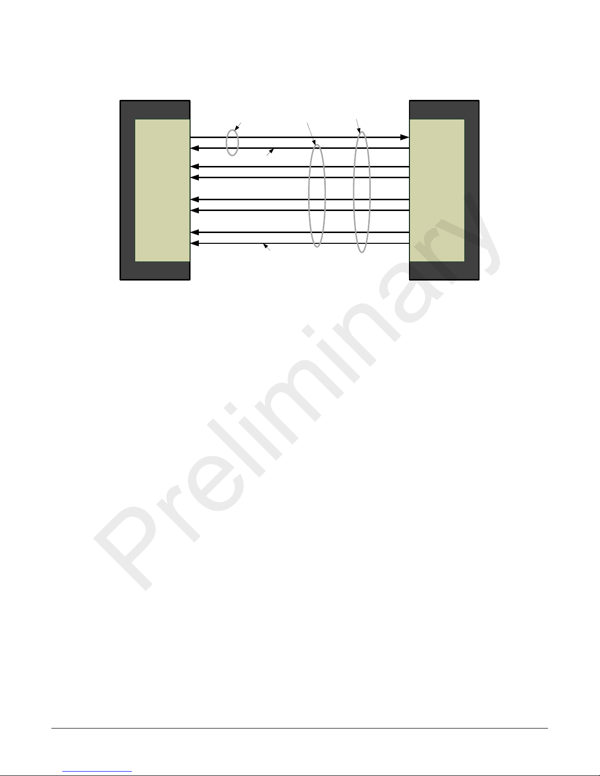
An important note on window blemishes
When flat field correction is performed, window cleanliness is paramount. The figure below shows
an example of what can happen if a blemish is present on the sensor window when flat field
correction is performed. The blemish will cast a shadow on the wafer. FFC will compensate for this
shadow by increasing the gain. Ess entially FFC will create a white spot to compensate for the dark
spot (shadow). As long as the a ngle of the incident light remains unchanged then FFC works we ll.
However when the angle of incidence changes significantly (i.e. w hen a lens is added) then the
shadow will shift and FFC will makes things worse by not correcting the new shadow (dark spot)
and overcorrecting where the shadow used to be (white spot). While the dark spot can be
potentially cleaned, the white spot is an FFC arte fact that can only be corrected by another FFC
calibration.
How to do an FFC Setup in the Camera
timeout of 20 seconds p er command, which is too short for the FFC c alibration to run
fully. You can change the default timeout by setting a command line argument in the
short-cut:
• Right click on the short-cut in the start menu and select properties.
• Add –timeout 600 to increase the command timeout to 10 minutes (See
below)
• Repeat for desktop short-cut
Figure 17: Setting the camera ’s timeout value
The calibration is performed in two steps. The fixed offset FPN (base and Delta) is determined first
by performing an aver aging without any light. This calibration determines exactly how much offset
to subtract per pixel in order to obtain flat output when the sensor is not exposed.
Camera Operation Falcon 4 Camera User's Manual • 37

Preliminary
If the calibration finds any defective pixels, where its FPN base value is greater than Pixel
Replacement Offset Threshold, or its PRNU value is greater than Pxiel Replacement Gain Threshold,
the pixel can be replaced if Pixel Replacement Mode is Active.
The gain (PRNU) calibration is performed next to de termine the multiplication factors required to
bring each pixel to the required value (target) for flat, white output. For the monochrome cameras,
the target is determined by the user (See flatfieldCalibrationTarget).
It is important to do the FPN c orrection first. Results of the FPN correction are used in the PRNU
procedure.
Let’s go through a flat field calibration example:
1. The camera is placed in internal exposure and frame rate. Ensure that the area of
interest (AOI) is set to the full window (i.e. Width=SensorWidth and Height=SensorHeight).
No other exposure mode or AOI configuration will allow FFC calibration. See ExposureMode,
TriggerMode, OffsetX, OffsetY, Width, Height.
2. Settings such as frame rate, exposure time, etc. are set as close as possible to the actual
operating conditions. Set system gain[All Digital] to 1 and background subtract to 0,
as these are the defaults during FFC calibration. See GainSelector, Gain, BlackLevelSelector,
and BlackLevel.
3. Select correction active set to user flat field x. Go to flat field correction mode, select
calibration. See flatfieldCorrectionCurrentActiveSet, and flatfieldCorrectionMode.
4. Clear existing coefficients. See flatfieldCalibrationClearCoefficient.
5. Place the camera in the dark (i.e. cover lens) and run FPN calibration. This performs the
FPN correction and saves the FPN coefficients to temporary memory. See
flatfieldCalibrationFPN.
6. Calibration mode enables both FPN and PRNU correction. Verify signal output is close to 0
DN.
7. Illuminate the sensor to 65 % saturation, using a high quality white referenc e.
8. Set flat field target to 80 % saturation (monochrome only). See flatfieldCalibrationTarget.
9. Select Gain Calib ration Mode as either High Gain or High Resolution
10. Run Gain (PRNU) calibration. See flatfieldCalibrationPRNU.
The defect pixel will be replaced if Pixel Replacement Mode is Active. A defective pixel is
defined as a pixel whose FPN base value is greater than Pixel Replacement Offset Threshold
or/and whose PRNU value is greater than Pixel Replacement Gain Threshold.
11. Save the flat field calibration: flatfieldCalibrationSave.
38 • Falcon 4 Camera User's Manual Camera Operation

Preliminary
Matching gain and offset values on multiple cameras
One way is of course to use flat field correction. All cameras would be set up under the same
conditions, including lighting, and then calibrated with FPN and PRNU. This process can be time consuming and complicated (especially the white target). Another way is to use global FPN (Sensor
Control > Black Lev el Selector > DigitalAll1):
1. Starting from factory se ttings (f actory flat field), take note what the highest dark offset is
among the set of cameras. If the highest dark offset is higher than about 20 DN you might
want to consider recalibrating the FPN correction. You can use the histogram feature
availab le in mos t image processing software applications (for example, Image-Pro), or in
CamExpert, to determine this value. Large differences in dark offset between the factory and
user are typically caused by differences in temperature from factory to user. Large dark
offsets will result in PRNU-correction-induced FPN and should therefore be avoided.
2. Decrease global FPN (increase the offset in dark) on all cameras until they are the same and
reach at least 6 DN.
3. Illuminate to about 80 % saturation and note the highest signal level among the set of
cameras.
4. Increase the system gain (Sensor Control > Gain Selector > DigitalAll1) on the cameras
until they all reach the same output level (highest of all cameras).
5. Place camera in the dark and repeat step 2 to 4 until both dark offset and 80 % sat signal
levels are equal on all cameras.
Defective Pixel Detection and Replacement
The camera has two methods of replacing pixels. Static pixel replacement uses the FFC coefficients
to mark pixels that will be replaced. Dynamic pixel re placement consists of a median filter that is
applied when the given pixel is above a threshold whe n compared to adjacent pixels.
Static Pixel Replacement
This is a technique for the elimination of dead or hot pixels. A p ixel on the left edge (beginning of
the line) would be replaced with the pixel to its right, while a pixel on the right edge (e nd of the
line) is replaced with the pixel to its left. Any pixel wit hin a line is replaced with the average of its
neighboring pixels (on the same line). For color sensors, the same algorithm is used except the
replacement pixel is of the same color. Note that three horizontally adjacent defective pixel cannot
be replaced.
The camera uses the FFC coefficients to indicate which pixels need to be replaced. If a pixel has a
Gain(PRNU) coefficient that is greater than the defectivePixelReplacementGainThreshold then the
pixel will be marked for replacement. Additionally, a pixel will be replaced if has an Base
Offset(FPN) coefficient that is greater than the offset pixel replacement threshold
(defectivePixelReplacementOffsetThreshold ). Lowering these thresholds will remove more pixels
with high gain and offset coefficients.
Most hot and dead pixels will be identified when a FPN or PRNU calibration is performed in camera.
The user can also manually mark a pixel for replacement by setting its Pixel Base Offset to 511.
Camera Operation Falcon 4 Camera User's Manual • 39

File Access via the CamEx p e rt Tool
Preliminary
1. Click on the “Setting…” button to show the file selection menu.
Figure 18 Initial File Access Control D ialog
2. From the Type drop menu, select the file type that will be uploaded to the camera.
3. From the File Selector drop menu, select the camera memory location for the uploaded data. This menu
presents only the applicable data locations for the selected file type.
4. Click the Browse button to open a typical Windows Explorer window.
5. Select the specific file from the system drive or from a network location.
6. Click the Download button to execute the file transfer from the Falcon4.
7. Note that firmware changes require a device reset command.
40 • Falcon 4 Camera User's Manual Camera Operation

Preliminary
Technical Specifications
Mechanicals
Technical Specifications Falcon 4 Camera User's Manual • 41

Appendix E: EMC Declaration of Conformity
Preliminary
TBD
42 • Falcon 4 Camera User's Manual Technical Specifications

Preliminary
Appendix A: GenICam
Commands
This appendix lists the available GenICam camera features. Access these features using the
CamExpert interface.
Parameters in gray are read only, either always or due to another parameter being disabled.
Parameters in black are user set in CamExpert or programmable via an imaging application.
Features listed in the description table but tagged a s Invisible are typically reserved for Teledyne
DALSA Support or third party software usage, and not typically required by end user applications.
Additionally the Standard column will indicate which parameter is a member of the custom DALSA
Features Naming Convention (denoted by DFNC), versus the GenICam Standard Features Naming
Convention (SFNC not s hown).
Camera Information Category
The camera information group provides general information about the camera. Parameters such as
camera model and firmware version uniquely identify the connected device. As well, temperature
can be monitored and user sets can be saved and loaded to and from the camera’s non-volatile
memory using the features grouped here.
Camera Information Feature Descriptions
The following table describes these parameters along with their view attribute.
Display Name Feature & Values Description Standard
& View
Device Vendor N a me DeviceVendorName Displays the device vendor name. (RO) Beginner
Device Model Name DeviceModelName Displays the device model na me. (RO) Beginner
Device Family Name DeviceFamilyName
Device Version DeviceVersion Displays the device version. This tag will also highlight if the
firmware is a beta or custom design. This is an automatically
generated number that specifically identifies the software build.
(RO)
Device Version DeviceManufacturerInfo This feature provides extended manufacturer information abo ut
the device, such as the firmwa r e d esign type. (R O)
Firmware Version DeviceFirmwareVersion Displays the currently loaded f irmware version number.
Firmware files have a unique number and have the .c b f file
extension. (RO)
Serial Number DeviceID Displays the device’s factory set camera serial number. (RO) Beginner
Device User ID DeviceUserID Feature to store a user-programmable identifier of up to 15
characters. The default factory setting is the camera serial
number. (RW)
Device Reset DeviceReset Resets the device to its power up state. (W) Beginner
Power-on User Set UserSetDefaultSelector Selects the camera configuration set to load and mak e active on
camera power-up or reset. The camera config uration sets are
stored in camera non-volatile memory. (RW)
Beginner
Beginner
Beginner
Beginner
Beginner
Appendix A: GenICam Commands Falcon 4 Camera User's Manual • 43

Software Default SoftwareDefault No default set is loaded. T he camera uses model default values
Preliminary
Factory Factory Load factory calibrated defaul ts .
UserSet1
to
UserSet 4
User Set Selecto r UserSetSelector Selects the camera config uration set to load feature settings
Factory Set Factory Select the default camera feature settings saved by the factory .
UserSet1
UserSet4
and no factory calibrated v alues.
Select the user def ined configur at ion (UserSet1 to UserSet8) as
to
the Power-up Configuration.
from or save current feature settings to. The Facto ry s et
contains default camera feature setti ngs . U s er c am era
configuration sets contain features settings previously saved by
the user. (RW)
Beginner
User Set 1
User Set 4
Load User Set UserSetLoad Lo ad s the camera configuration set specified by the User Set
Save User Set UserSetSave Saves the current camera configuration to the user set specified
Device Temperat ur e
Selector
FPGA Board FPGABoard Read FPGA Board temperature.
Sensor Board SensorBoard Read sensor board temperature.
Device Temperat ur e DeviceTemperature Displays the devic e temperature in degrees Celsius. Depending
DFNC Major Rev deviceDFNCVersionMajor Major revision of Dalsa Feature Naming Co nv ention which was
DFNC Minor Rev deviceDFNCVersionMinor Minor revision of Dalsa Feature Naming Convention which was
to
DeviceTemperatureSelector Select the source where t he t emperature is read. 1.00
Sensor Sensor Read sensor temperature.
UserSet1
to
UserSet4
Select the User Defined Configur at ion space (Us er Set 1 to
UserSet8) to save to or l o ad f ro m features settings previously
saved by the user.
Selector feature, to the camera and makes it active. Disabled
when flatfieldCorrectionMode = Calibration. (W)
by the User Set Sel ector feature. The user set s are located on
the camera in non-volatile memory. Disabled when
flatfieldCorrectionMode = Calibration or UserSetSelector =
Factory. (W)
on the host application (e.g. GUI). This value is a polled value
and may automatically be updated every second. Otherwise the
value will only be updated upon connec tion or when the
temperature selector is changed.
used to create the device’s XML. (RO)
used to create the device’s XML. (R O)
Beginner
Beginner
Beginner
Beginner
DFNC
Invisible
DFNC
Invisible
44 • Falcon 4 Camera User's Manual Appendix A: GenICam Commands

Preliminary
Acquisition and Transfer Control Category
The acquisition and transfer control category, as show n by CamExpert, group ac q uisition and
transfer specific parameters.
Acquisition and Tr ansfer Control Feature Descriptions
The following table describes these parameters along with their view attribute.
Display Name Feature & Values Description Standard
& View
Acquistiion Mode AcquisitionMode Acquisition mode of the camera. Beginner
Continuous Continuous Frames are captured continuously until stopped with
Acquisition Status AcquisitionStatus This feature reports if the camera is currently
Acquisition Start AcquisitionStart Starts the acquisition of the device. The number o f
Acquisition Stop AcquisitionStop Stops the acquisition of the device at the end of the
the Acquisition Stop command.
Beginner
transmitting image data. < R O >
Beginner
frames captured is specified by Acquisition Mode
feature.
Beginner
current frame(s ) sequence.
Sensor Control Category
The camera sensor controls, as shown by CamExpert, group sensor specific parameters.
Sensor Control Feature Descriptions
The following table describes these parameters along with their view attribute.
Display Name Feature & Values Description Standard
& View
Device Scan Type DeviceScanType Scan type of the sensor. < RO> Beginner
Areascan Areascan 2D areascan sensor.
Sensor Color Type sensorColorType Defines t h e c a mera sensor color type. < RO > Beginner
Monochrome Sensor Monochrome Sensor color type is monochrome.
Sensor Width SensorWidth Defines the sensor width in active pixels.
< RO>
Sensor Height SensorHeight Defines the sensor height in active lines.
< RO>
Input Pixel Size pixelSizeInput Size of the image input pixels, in bits per pixel.
< RO >
12 BPP Bpp12 Sensor output data path is 12 bits per pixel.
Frame Rate AcquisitionFrameRate Specifies the camera internal frame rate, in Hz. (Read-
only when TriggerMode = "On")
1 to x Hz (where x is a calc ulated maximum)
The maximum value of the fram e rate is the result of a
complicated formula and is dependant on the following
features:
Height, summingMode, pixelformat
Note that any user entered value is automatically
adjusted to a valid camera value.
Exposure Mode ExposureMode Sets the operation mode for the camera’s exposure. Beginner
DFNC
Expert
Expert
Expert
DFNC
Beginner
Appendix A: GenICam Commands Falcon 4 Camera User's Manual • 45

Timed Timed The exposure duration time is set using the Exposure
Preliminary
Time feature and the exposure starts with a LineStart
event.
Trigger Width TriggerWidth Uses the width of the trigger signal pulse to control the
exposure duration. Use the Trigger Activation feature
to set the polarity of the trigger. The Trigger Width
setting is applicable when the LineStart trigger is
enabled and a signal is selected as trigger source.
Exposure Time ExposureTime Sets t he exposure time (in microsec o n d s) when the
Exposure Mode f ea t ur e is set to Timed .
Beginner
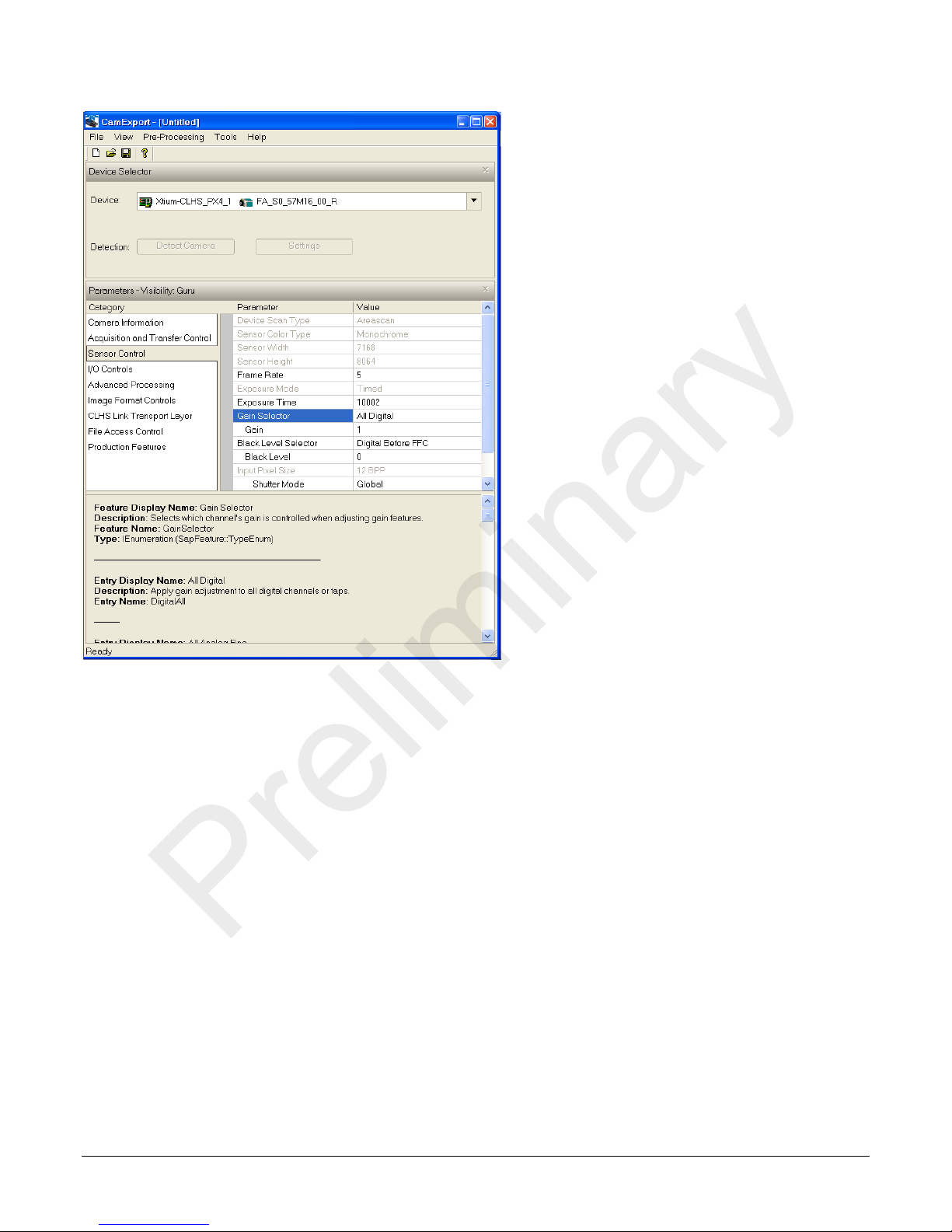
Gain Selector GainSelector Selects which g a in is controll ed when adjusting
All Digital DigitalAll Apply a digital gain adjustment to the entire image.
Analog Fine (Raw) AnalogAllRaw1 Apply fine gai n adj ustment to all analog taps express in
Analog Tap1 to Tap11 AnalogTap0 to 10 Apply fine gain adjustment to individual taps in raw
Gain Gain Sets the selected gain as an ampli fication factor applied
Black Level Selector BlackLevelSelector Selects which tap is controlled by the Black Level
Digital All DigitalAll
Black Level Selector BlackLevelSelector Selects which black level (i.e. dark offset) is controlled
Digital Before FFC DigitalAll1 Global FPN. Apply black level adjustment to all digital
Digital After FFC DigitalAll2 Background Subtract. Apply black level adjustm ent to
Background Add BackgrounAdd Add a digital value to the image before FFC(tbc)
Analog AnalogAll1 Apply black lev el adjustment to all analog taps.
Black Level BlackLevel Black level (offset) in DN Expert
Black Level Tap Offset
Selector
Black Level Tap Offset blackLevelTapOffset Amount to add or subtract to adjus t the black level on
Analog Tap 0 to 11 Tap1 to Tap11 Apply offset correction to the selected tap.
Automatic Black Level Tap
Balancing
On Demand OnDemand The camera performs a tap balance at start up and
Perform Tap Balance blackLevelBalanceTaps Automatically calibrates the black level o n the senso r’s
Input Pixel Size pixelSizeInput Size of the pixel that is digitized by the sensor, in bits
12 BPP Bpp12 12 bits per pixel. (RO)
Shutter Mode shutterMode
Global Global All pixels integrate simultaneously and then held
Rolling Rolling The rows of the sensor integrate light at slightly
blackLevelTapBalanceOffsetSele
ctor
Tap balancing adjusts the black level on a per sensor
Off Off The camera does not perform tap balancing.
gain features.
raw sensor value..WARNING: This may invalidate
calibrations.
sensor value.
to the image.
feature.
when adjusting the black level feature.
channels or taps, before flat field correction.
all digital channels or taps, after flat fi eld correction.
Selects which tap’s offset is controlled by the Black
Level Tap Offset feature.
the selected sens or tap.
tap. It is done after the FFC.
when the user clicks the blackLevelBalanceTaps
command.
taps.
per pixel.
constant until they can be read. This is at the cost of
higher noise.
different times. This c an ca use image artefacts.
Especially if the scene is moving.
Beginner
Beginner
Beginner
Beginner
DFNC
DFNC
Expert
DFNC
Expert
DFNC
Guru
Guru
Guru
46 • Falcon 4 Camera User's Manual Appendix A: GenICam Commands

Beginner
Beginner
Use external trigger
Beginner
Preliminary
I / O Control Category
The camera’s I / O controls, as shown by CamExpert, group features used to configure external
inputs and acquisition actions based on those inputs, plus camera output signals to other devices.
I/O Controls Feature Descriptions
The following table describes these parameters along with their view attribute.
Display Name Feature & Values Description Standard
& View
Trigger Select or TriggerSelector Displays the type of trigger to co nf igure with the various
FrameStart FrameStart Selects a trigger starting the capture of a single frame.
Trigger Mode TriggerMode Enables and disables ex ternal frame trigger.
Off Off Use internal trigger.
On On
Trigger Source TriggerSource Specifies the internal signal or input line to use as the
Software Software CLHS Trigger message from the frame grabber
LinkTrigger0 LinkTrigger0 General Purpose Input Line 1
Line1 Line1 General Purpose Input Line 2
Line2 Line2 Software trigger through the TriggerSoftware command
Software Trigger TriggerSoftware Generate an i nternal trigger. Available when the trigger
Trigger Delay TriggerDelay Specifies the delay in microseconds to ap p ly after the
LineSelector LineSelector Selects the logical line of the device to configure. Beginner
General Purpose Input 1 Line1 General Purpose Input 1
General Purpose Input 2 Line2 General Purpose Input 2
General Purpose Output 1 Line3 General Purpose Output 1
General Purpose Output 1 Line4 General Purpose Output 1
Line Mode LineMode Returns if the selected physical pin is used as an input or
Input Input The selected physical pi n is used as an input.
Output Output The selected physical p in is used as an output.
Line Pinout linePinAssociation Gets the physical pin location as s oc iated with the logical
H1_Pin6Pos_Pin5Neg H1_Pin6Pos_Pin5Neg General Purpose Input 1:
H1_Pin11Pos_Pin12Neg H1_Pin11Pos_Pin12Neg General Purpose Input 2:
H1_Pin3_Pin4 H1_Pin3_Pin4 General Purpose Output 1:
Trigger features. <RO>
trigger source. <RO>
The trigger mod e must be set to On.
mode is enabled and the trigger source is equal to
Software.
trigger reception before activa ting it. Possible values are:
0 - 281474976710655 µs
output signal. <RO>
line. The H1 prefix refers to the Hirose Power and input
cable (see Figure 6). <RO>
Hirose Pin 6 Positive, Pin 5 Negative.
Hirose Pin 11 Positive, Pin 12 Negative.
Hirose Pin 3 , Pin 4.
Beginner
Beginner
Beginner
DFNC
Beginner
Appendix A: GenICam Commands Falcon 4 Camera User's Manual • 47

H1_Pin7_Pin8 H1_Pin7_Pin8 General Purpose Output 2:
Preliminary
Hirose Pin 7, Pin 8.
Line Debouncing Peri od lineDebouncingPeriod Specifies the minimum length of an input line voltage
Line Inverter Line Inverter Controls whether to invert the selected input or output
True True Invert signal.
False False Do not invert signal.
Line Status LineStatus Returns the current status of the selected input or output
True True Selected signal is high.
False False Selected signal is low.
Output Line Source outputLineSource Selects which internal signal or softw a re co ntrol state to
Off Off
Software Controlled SoftwareControlled The value of the output line is determined by
Pulse On: Start of Exposure PulseOnStartofExposure Generate a pulse when the senso r ac tually starts
Pulse On: End of Exposure PulseOnEndofExposure Generate a pulse when the sensor stops exposing its
Pulse On: Start of Readout PulseOnStartofReadout Generate a pulse when the sensor starts reading i ts
Pulse On: End of Readout PulseOnEndofReadout Generate a pulse when the sensor stops reading its
Pulse On: GP Input 1 PulseOnInput1 Generate a pulse when the General Purpose Output 1
Pulse On: GP Input 2 Pulse OnInput2 Generate a pulse when the General Purpose Output 2
Output Line Pulse Delay (in
Us)
Output Line Pulse Durarti o n
(in Us)
Output Line Value outputLineValue Selects the state of the output on the selected line. The
Active Active Sets the Output circuit to close.
outputLinePulseDelay Sets the delay before the output line pulse duration is
outputLinePulseDuration 0 to 8388608 µs
transition before recognizing a signal transition. Available
when the Line Selector is set to an input. Each input line
stores its own debouncing period.
Possible values are: 1 to 255 µs.
line signal.
line. This is a polled feature that requires the host to poll
the camera for the latest value.
output on the selected line. The pulse is defi ned b y
outputLinePulseDelay and outp utLinePulseDuration.
Note: the LineMode feature must be set to Output.
The output line is open
outputLineValue, outputLineSoftwareLatchControl and/or
outputLineSoftwareCmd.
exposing its pixels. (Slight delay after EXSYNC)
pixels.
pixels.
pixels.
goes active.
goes active
output.
Note: LineMode feature must be set to Output and
outputLineSource is not equal to Off or
SoftwareControlled.
Sets the duration of the output pulse.
Possible values are: 0 to 8388608 µs
Note: LineMode feature must be set to Output and
outputLineSource is no t equa l to Off or
SoftwareControlled.
Value will be applied immediately if the
outputLineSoftwareLatchControl f eature i s equal to OFF.
The Value will be applied when the
outputLineSoftwareCmd feature is set if the
outputLineSoftwareLatchControl feature is equal to
LATCH.
Note: LineMode feature must be set to Output and
outputLineSource set to SoftwareControlled.
DFNC
Beginner
Beginner
Beginner
DFNC
Beginner
DFNC
Beginner
DFNC
Beginner
DFNC
Beginner
48 • Falcon 4 Camera User's Manual Appendix A: GenICam Commands

Preliminary
Inactive Inactive Inactive - Sets the Output circuit to open.
Line Detectio n Level lineDetectionLevel The voltage at which the signal is treated as a lo gical
2.4V Threshold Threshold_2_4
Threshold_6_0 Threshold_6_0 6V threshold: for 12V input
Threshold_12_0 Threshold_12_0 12V theshold: for 24V input
Line Status All LineStatusAll Returns the current status of all available line signals , at
Output Line Software Latch
Control
Latch Latch Changes to the output line value are applied when the
Output Line Software
Command
outputLineSoftwareLatchControl The software latch allows the user to set more than 1
Off Off Changes to the output line value are applied immediately.
outputLineSoftwareCmd Contains a bit field representing whether to apply to
high. Available when the Line selector i s set to a general
purpose input (GPI).
Note: This value is for both general purpo s e inputs (i.e.
setting this value sets i t f o r b o th L ine 1 and Line 2).
2.4V threshold: for TTL inputs
time of polling, in a single bitfield. This is a polled feature
that requires the host to poll the camera fo r the latest
value. <RO>
The order is Line1(LSB), Line2, Line3, Line4/
7 6 5 4 3 2 1 0
Not used Line 4 Line 3 Line 2 Line
1(LSB)
output simultaneous ly
OutputLine that are currently in Software Latc h c o ntrol
will only set with the value in OutputLineValue with the
outputLineSoftwareCmd feature.
Output Line Software Command is triggered.
cached outputLineValue values.
Value
0 Don’t apply any value
1 Apply outputLineValue of Output1
2 Apply outputLineValue of Output2
3 Apply outputLineValue of Output1 and
Output2
Note: LineMode feature must be set to Output and
outputLineSource is set SoftwareControlled.
DFNC
Beginner
Beginner
DFNC
Beginner
DFNC
Beginner
Appendix A: GenICam Commands Falcon 4 Camera User's Manual • 49

Advanced Processing Control Category
DFNC
Off
Off
Flat field correction is disabled.
Active
ActiveAll
Flat field correction is enabled. FPN and PRNU
correction is active.
Active, FPN Only
ActiveFPNOnly
FPN correction is active.
Active, PRNU Only
ActivePRNUOnly
PRNU correction is active.
Calibration
Calibration
DFNC
DFNC
DFNC
Preliminary
The camera’s Advanced Processing controls, as shown in CamExpert, group parameters used to
configure Defective Pixel Detection, Flat Field calibration.
Advanced Processing Control Feature Descriptions
The following table describes these parameters along with their view attribute.
Display Name Feature & Values Description Standard
& View
Correction Mode flatfieldCorrectionMode Sets the mode for flat field correction.
Beginner
The camera is configured to calibration mode
(Only available when TriggerMode=Off,
flatfielCorrectionCurrenActiveSet is not
FactoryFlatfield,).
The device may automatically adjust some
features in the camera when calibration mode is
enabled. The features that are automaticall y
adjusted are device specific. The device w ill not
restore these features when the flat field
correction mode is changed from calibration
mode to another mode.
It is not available for FactoryFlatfield1 [Global
Shutter Factory Flat Field] ,FactoryFlatfield 2
[Rolling Shutter Factory Flat Field].
It is not available for external mode, and it is
not available for smaller AOI than 2048
horonzatal.
Correction Algorithm flatfieldCorrectionAlgorithm Selects the algorithm to use for calib ration of
Method1 Method1 The following formula is used to calculate the
Correction Type flatfieldCorrectionType Specifies the flat field correction type. <RO>
Area-based AreaBase Flat field correction is based on an entire image
Current Active Set flatfieldCorrectionCurrentActiveSet Specifies t h e c u rr en t set of flat field coefficients
Global Shutter
Factory Flat Field
Rolling Shutter
Factory Flat Field
User Flat Field 1
User Flat Field 3
Pixel X Coordinate flatfieldCorrectionPixelXCoordinate Specifies the X coordinate of the flat field pixel
to
FactoryFlatfield1 Factory calibrated flat field for Glob al Shutter
FactoryFlatfield2 Factory calibrated f lat field for Rolling Shutter
UserFlatfield1
UserFlatfield3
flat field coefficients. <RO>
flatfield corrected pixel:
newPixelValuex,y = (sensorPixelValuex,y –
normalized FFCOffsetx,y) * FFCGain[x][y]
(array)
to use. This feature cannot b e cha ng ed w hile
the camera is in flat field calibration mode.
Read-Write (Read-Only when in Calibration
Mode).
Mode
Mode.
User Flat Field 1 to User Flat Field 3: User
to
configurable flat field sets
coefficient to access. To configure, set
Correction Mode to Calibration.
Beginner
Beginner
Beginner
Beginner
50 • Falcon 4 Camera User's Manual Appendix A: GenICam Commands

Preliminary
Pixel Y Coordinate flatfieldCorrectionPixelYCoordinate Specifies the Y coordinate of the flat field pixel
Pixel Gain(PRNU) flatfieldCorrectionGain Sets the gai n to ap p ly to the currently selected
Pixel Base
Offset(FPN)
Pixel Delta
Offset(FPN)
Clear Coefficients flatfieldCalibrationClearCoefficient This feature is used t o clear all the current FPN
Offset(FPN)
Calibration
Gain Calibration
Target
Calibration Sample
Size
Average 256 images Avg256 Average 256 images.
Average 128 images Avg128 Average 128 images.
Average 64 images Avg64 Average 64 images.
Average 32 images Avg32 Average 32 ima ges.
Average 16 images Avg16 Average 16 ima ges.
Gain(PRNU)
Calibration
Save Calibration flatfieldCalibrationSave Saves the current flat field coef ficients in the
Copy Source flatfieldCoefficientsCopySource Selects the flatfield coeffici ents s et to c o p y to
Global Shutter
Factory Flat Field
Rolling Shutter
Factory Flat Field
User Flat Field 1
User Flat Field 3
flatfieldCorrectionOffsetBase Controls whether to invert the selected input or
flatfieldCorrectionOffsetDelta Sets the offset to apply to the currently
flatfieldCalibrationFPN Performs fixed pattern noise (F PN ) calibration.
flatfieldCalibrationTarget Sets the target pixel value for the gai n ( PR NU)
flatfieldCalibrationSampleSize The number of images to average to p er form
flatfieldCalibrationPRNU Performs photo response non-uniformity
FactoryFlatfield1 Factory calibrated f lat field for Glob al Shutter
FactoryFlatfield2 Factory calibrated f lat field for Rol ling Shutter
UserFlatfield1
to
UserFlatfield3
coefficient to access. To configure, set
Correction Mode to Calibration.
pixel. Range is from 1 to 4, as float.
To configure, set Correction Mode to
Calibration.
output line signal.
selected pi xel.
Range is 0 to 511, as float.
Read-Write when in Calibration Mode.
and PRNU coefficients in the selected Active
Set.
Read-Write when in Calibration Mode
FPN calibration eliminates fixed pattern noise by
subtracting all non-uniformities and dark
current to obtain near 0 DN output in the dark
(no light exposed to the sensor). This currently
can take up to 5 minutes.
Read-Write when in Calibration Mode
calibration. It is specified as a percentage of the
output range (for example, 4096 DN for 12
bits).
Range is 0 to 100 %, as flo at.
Read-Write when in Calibration Mode.
the calibration.
(PRNU) calibration.. PRNU calibration eliminates
the difference in responsiv ity between the mos t
and least sensitive pixel, creating a uniform
response to light. See the
Calibration section in Appendix D: Internal Flat
Field Calibration Algorithms. Read-Write when
in Calibration Mode
Active Set. Read-Write when in Calibration
Mode.
the current Active Set. Read-Write when i n
Calibration Mode
Mode
Mode.
User Flat Field 1 to User Flat Field 3: User
to
configurable flat field sets
Gain (PRNU)
DFNC
Beginner
Beginner
DFNC
Expert
DFNC
Expert
DFNC
Expert
DFNC
Beginner
DFNC
Expert
DFNC
Expert
DFNC
Expert
Appendix A: GenICam Commands Falcon 4 Camera User's Manual • 51

Copy Coefficient to
DFNC
Preliminary
Active
Pixel Replacement
Mode
Active Active Enable defective pixel repla cement
Pixel Replacement
Offset Threshold
Pixel Replacement
Gain Threshold
Pixel Replacement
Algorithm
Average/Copy
Adjacent
Average/Weighted
Average
FPN Base Defect
Count
flatfieldCoefficientsCopyInCurrent Copies the currently selected flat field
coefficients in the Acti ve Set. Read-Write when
in Calibration Mode
defectivePixelReplacementMode Enable or disable pixel replacement.
If Active: If FPNx,y >
defectivePixelReplacementOffsetThreshold OR
PRNUx,y >
defectivePixelReplacementGainThreshold, then
Pixelx,y is replaced using the algorithm below.
Off Off Disable pixel replacement
defectivePixelReplacementOffsetThreshold The FFC base offset value(FPN) above which the
pixel are deemed hot pixels and replaced. This
value can be adj u s t ed to replace more or fewer
pixels.
Possible values are:1 to 4096, as flo at
defectivePixelReplacementGainThreshold The FFC gain value (PRNU) above which the
pixel are deemed dead pixels and replaced. This
value can be adj u s t ed to replace more or fewer
pixels.
Possible values are:1 to 4, as f loat
defectivePixelReplacementAlgorithm Selects the pixel replacement algo rithm. DFNC
Method1 The algorithm consists of averaging the
adjacent pixels when replacing a single defect
and copying the nearest pixel when replacing
two consecutive defects or a def ect at the
beginning or end of a line, i.e.
A= pixel A
B= pixel B
X= defect
AXB is corrected to ACB where:
C= (A+B)/2
AXXB is corrected to AABB
XA is corrected to AA
BX is corrected to BB
Method4 Algorithm consists of averaging the adjacent
pixels when replacing a single defect and
performing a weighted average when replacing
two consecutive defects. A defect at t he
beginning or end of a line is not corrected, i.e.
A= pixel A
B= pixel B
X= defect
AXB is corrected to ACB where:
C= (A+B)/2
AXXB is corrected to ACDB where
C = (11 *A + 5*B)/16
D = (5*A + 11*B)/16
XA is not corrected
BX is not corrected
flatfieldCalibrationFPNBaseDefectCount Reports the number of defec t pixels detect ed in
FPN base calibrati o n.
DFNC
Expert
DFNC
Expert
DFNC
Guru
DFNC
Guru
Expert
Guru
52 • Falcon 4 Camera User's Manual Appendix A: GenICam Commands

DFNC
DFNC
DFNC
DFNC
Guru
DFNC
Guru
DFNC
Guru
Preliminary
FPN Delta Defect
Count
PRNU Defect Count flatfieldCalibrationPRNUDefectCount Reports the numb er o f defect pixels detected in
LUT Mode lutMode Enables or disables the linearization look up
Active Active Enable linearization look up table
Calibration Calibration1 Allow the user to calibrate the LUT
LUT Tap Selector lutTapSelector LUT tap selector.
LUT Index lutIndex Linearization LUT index.
LUT Value lutValue Linearization LUT Value.
flatfieldCalibrationFPNDeltaDefectCount Repo r ts the number of defec t pixels detect ed in
FPN delta calibration.
PRNU delta cali bration.
table correction.
Off Off Disable linearization look up table.
Guru
Guru
Expert
Appendix A: GenICam Commands Falcon 4 Camera User's Manual • 53

Beginner
Beginner
Beginner
Beginner
Beginner
Beginner
Beginner
Beginner
Beginner
Preliminary
Image Format Controls Category
The camera Image Format controls, as shown by CamExpert, groups parameters used to configure
camera pixel format, and image cropping, Additionally, a feature control to select and output an
internal test image simplifies qualifying a camera setup without a lens.
Parameters in gray are read only, either always or due to another parameter being disabled.
Parameters in black are user set in CamExpert or programmable via an imaging application.
Features listed in the description table but tagged a s Invisible are usually for Teledyne DALSA
Support or third party software usage—not typically required by end user applications.
The following table describes these parameters along with their view attribute and minimum
camera firmware version required. Additionally the table will indicate which parameter is a member
of the DALSA Features Naming Convention (DFNC), GenICam Standard Features Naming
Convention or custom camera feature.
Display Name Feature & Values Description Standard
& View
Width Width Width of the I m age provided by the device (in pix e ls ).
Height Height Height of the I m ag e provided by the d e vice (in lines).
Offset X OffsetX Horizontal off set from the Senso r Origin to the Area
Offset Y OffsetY Vertical o ffset from the S e ns o r Origin to the Area O f
Pixel Format PixelFormat Output image pixel co ding format of the s e ns or..
Mono12 Mono12 Mono12: Monochrome 12-Bit
Mono16 Mono16 Mono16: Monochrome 16-Bit
Pixel Color Filte r PixelColorFilter Indic a te s the ty pe of color f ilte r applied to the image .
None None No filter applied on the senso r .
Pixel Coding PixelCoding Output imag e p ixel coding for mat of the sensor.
Mono Mono Monochrome format.
Pixel Size PixelSize Number of bits per pixe l< RO>
Bpp12 Bpp12 12-bits per pixel.
Bpp16 Bpp16 16-bits per pixel
Test Image
Selector
Grey Horizontal
Ramp
Grey Vertical Ramp GreyVerticalRamp Image is filled vertically w ith an im ag e that goes from
Purity Purity Image is filled with an image that goes from the
TestImageSelector Selects the type of test image o utput by the camera.
Off Off Image is from the camera sensor.
GreyHorizontalRamp Image is filled ho rizontally with an image that go e s
Of Interest (in pixels).
Interest (in pixels ).
<RO>
<RO>
See the Test Patterns se c tion for more information.
Flatfield corr e c tion will be disabled if the user selects
the PRNU value.
from the darke s t p ossible value to the b r ightest.
the darkest poss i b le value to the brightest.
darkest poss ib le value to the brightest b y 1 Dn
increment per frame.
54 • Falcon 4 Camera User's Manual Appendix A: GenICam Commands

DFNC
DFNC
Off
Off
The camera will output 1 frame at a time.
Active
Active
The camera will sum 2 or more frames and output the
summed image
DFNC
DFNC
DFNC
Preliminary
Grey Diagonal
Test Image Static
Value
Summing Mode summingMode Enables camera summing mode.
Summing Count (in
frame)
Burst Mode summingBurst Enables camera summing burst mode. This mod e
Median Filter medianFilter
Median Filter
Threshold
Ramp
Static Value Static Value User-specif ie d static value. The value is se t us i ng the
PRNU PRNU This is 2 times the sum of a horizontal test pattern
testImageStaticValue Pixel value to use for test imag e w he n the
summingCount Specifies the number of frames to sum. Read-Write
Active Active When the camera is triggered (either internally or
Off Off The camera to average the specified number of
Active Active Active: The ca me ra will use 3x3 2D m e d ian filter
Off Off The camera will not use 3x3 2D median filter
medianFilterThreshold Specifies the m e d ian filter threshold. If the differe nc e
GreyDiagonalRamp Image is filled horizontally and v e rtically with an
image that goes fro m the darkest possib l e v alue to
the brightest by 1 D n inc rement per pixel.
testImageStaticValue feature.
that repeats every 64 pixels and a v e rtical test pattern
that repeats every 62 lines plus +
testImageStaticVa lue . This te s t p a tte r n c an be used to
test FPN and PRNU correction.
TestImageSelector feature is set to “Static V a lue ” .
Read-Write when TestI m ag e S e l e c to r is either PRNU,
or StaticValue.
Possible values ar e : 0 to 4095
when summingMode is Active.
Possible values ar e : 2 to 8, in increments of 1.
effects the maximum frame rate(i.e.
AcquistionFrameRate). Read-Write when
summingMode is Active.
externally), it will gene r a te a s e r i e s (s umm ing C ount) of
internal triggers at the ma x im um frame rate. For
example, when the camera is set to a frame rate of 1
Hz in this mode, and the summingCount = 4, the
camera will generate 4 triggers at the maximum
frame rate every second.
frames(summingCo unt) as it receives the internal or
external frame tr ig gers.
between the curre nt p ixl and median of its neig hb or
pixels is greater than this value, the current p ixel will
be replaced.
Possible values ar e 0 to 255, in increments o f 1.
Beginner
Guru
Guru
Gur
Guru
Appendix A: GenICam Commands Falcon 4 Camera User's Manual • 55

CLHS Link Transport Layer Category
DFNC
DFNC
DFNC
Beginner
DFNC
Beginner
DFNC
DFNC
DFNC
DFNC
DFNC
DFNC
DFNC
Beginner
DFNC
DFNC
Preliminary
The camera’s CLHS Link Transport Layer category groups parameters used to document and
configure the Camera Link HS input and output of the camera.
Parameters in gray are read only, either always or due to another parameter being disabled.
Parameters in black are user set in CamExpert or programmable via an imaging application.
Features listed in the description table but tagged as Invisible are usually for Teledyne DALSA
Support or third party software usage—and are not typically required by end user applications.
Camera Link Transport Layer Feature Description
The following table describes the category’s parameters along with their view attribute and
minimum camera firmware version required. Additionally the table will indicate which parameter is
a member of the DALSA Features Naming Convention (DFNC), GenICam Standar d Features Naming
Convention, or a custom camera feature.
Display Name Feature & Values Description Standard
& View
LLDeviceID LLDeviceID A unique number ass ig ne d by the frame gr abber to the
camera.<RO>
Possible values are: 0 to 4294967295
PortID PortID The logical number of the CLHS port use d . A CLHS port is
defined as a command channel and may include the v i d e o
channel carried by a c able. <RO>
Possible values are: 0 to 4294967295
Avail Ports AvailPorts Number of ports ava ilable on this device. <RO>
Beginner
Beginner
Actual Device Config ActualDeviceConfig The current index o f the device configur a tio n. <RO>
Next Device Co nfig NextDeviceConfig The ne xt configuration of the device to use o n the ne xt hot
Device Config urre
Index
Elec Swap ElecSwap Indicates whe the r logical and physic al port numbers can
Data Rep DataRep Indicates whether v e rtical seam data can be duplicated
Row Dup RowDup Indicates whether row data can be duplic a te d ac ross
Data Split Mode DataSplitMode Defines the type o f data splitting across ca b le s a llo wed.
SinglePort SinglePort There is only o ne p ort so no splitting is p ossible.
Avail Ports Required AvailPortsRequired Defines the num b e r of connector s /p orts used in this
Port 0 Lanes
to
Port 7 Lanes
DeviceConfigureIndex Index selector for the de v i c e c o nfiguration.
Port0Lanes
to
Port7Lanes
plug event.
Possible values arae 1 or 2.
Possible values arae 1 or 2.
be swapped. <RO>
across cables. <RO>
cables. <RO>
<RO>
configuration. <RO>
Indicates the number of data lanes suppo r te d by Port X.
<RO>
Beginner
Beginner
Beginner
Beginner
Beginner
Beginner
Beginner
Beginner
56 • Falcon 4 Camera User's Manual Appendix A: GenICam Commands

DFNC
DFNC
DFNC
DFNC
Guru
Firmware
Firmware1
Writing a new firmware here will update the
camera.
User Flat Field 1
User Flat Field 3
FlatFieldCoefficients1
FlatFieldCoefficienets3
A tiff containing the fl at field correctio n
Factory Glob al Flatfield
FlatFieldCoefficientsFact1
A tiff containing the f ac to ry flat field correction
gain and offset)
Factory Rolling Flatfield
FlatFieldCoefficientsFact2
A tiff containing the f ac to ry flat field correction
gain and offset)
Logs
Logs
Dowload camer a logs. This is a zipped file
Defect Map
DefectMap
Download camera defect map.
Test File
TestFile
File that allows user to te s t file transfer.
Global Shutter,Tap 1,Column
1, Even Rows
LutLuminance1Tap1
Luminance LUT for Global Shutter Tap 1,, Pixels
0 - 1791, Even Rows.
Global Shutter,Tap 2,Column
1,Odd Rows
LutLuminance1Tap2
Luminance LUT for Global Shutter Tap 2, Pixels
0 - 1791, Odd Rows
Global Shutter,Tap 3,Column
2, Even Rows
LutLuminance1Tap3
Luminance LUT for Global Shutter Tap 3, Pixels
1792 - 3583, Even Rows
Global Shutter,Tap 4,Column
2,Odd Rows
LutLuminance1Tap4
Luminance LUT for Global Shutter Tap 4, Pixels
1792 - 3583, Odd Rows
Global Shutter,Tap 5,Column
3,Even Rows
LutLuminance1Tap5
Luminance LUT for Global Shutter Tap 5, Pixels
3584 - 5375, Even Rows
Global Shutter,Tap 6,Column
3,Odd Rows
LutLuminance1Tap6
Luminance LUT for Global Shutter Tap 6, Pixels
3584 - 5375, Odd Rows
Global Shutter,Tap 7,Column
4,Even Rows
LutLuminance1Tap7
Luminance LUT for Global Shutter Tap 7, Pixels
5376 - 7167, Even Rows
Global Shutter,Tap 8,Column
4,Odd Rows
LutLuminance1Tap8
Luminance LUT for Global Shutter Tap 8, Pixels
5376 - 7167, Odd Rows
Rolling Shutter,Tap
1,Column 1,Even Ro ws
LutLuminance2Tap1
Luminance LUT for Ro lling Shutter Tap 1,, Pixels
0 - 1791, Even Rows
Preliminary
Activate Hot Plug ActivateHotPlug Performs a Hot Plug event. This e v e nt w i ll c aus e the
8b/10b ErrorCount LinkErrorCount Indicates the number o f low level data errors on the
Refresh Features ReadLinkError Updates the LinkErrorCount featur e w ith the la te s t c o unt of
CameraLink HS
Speed in Mbps
clDeviceClockFrequency Indicates the Camera Link HS clock fre q ue nc y. The CLHS
camera to:
• disconnect from the fr a me g rabber
• load the configuration specified b y NextDeviceConfig if it
has changed since the last c onnection
• reconnect to the frame grabber.
connection betwee n the c a me ra and frame grab b e r. <RO>
Possible values are: 0 to 4294967295
the link errors.
clock runs at 3125 Mbits/second.
Beginner
Beginner
Beginner
Beginner
File Access Control Category
The File Access control in CamExpert allows the user to quickly upload var ious data files to the
connected Falcon4 came ra. The supported data f iles are for Falcon4 firmware upda t es, Flat Field
coefficients, and files to debug the camera.
Display Name Feature & Values Description Standard
& View
File Selector FileSelector Selects the file to access. The file types which
are accessible are device-dependent.
to
to
coefficients (i.e. g a in and offset)
coefficients f o r global shutter op e ration (i.e.
coefficients f o r rolling shutter op e ration (i.e.
Appendix A: GenICam Commands Falcon 4 Camera User's Manual • 57

Rolling Shutter,Tap
2,Column 1,Odd R ows
LutLuminance2Tap2
Luminance LUT for Ro lling Shutter Tap 2, Pixels
0 - 1791, Odd Rows
Rolling Shutter,Tap
3,Column 2, Even Ro ws
LutLuminance2Tap3
Luminance LUT for Ro lling Shutter Tap 3, Pixels
1792 - 3583, Even Rows
Rolling Shutter,Tap
4,Column 2,Odd R ows
LutLuminance2Tap4
Luminance LUT for Ro lling Shutter Tap 4, Pixels
1792 - 3583, Odd Rows
Rolling Shutter,Tap
5,Column 3,Even Ro ws
LutLuminance2Tap5
Luminance LUT for Ro lling Shutter Tap 5, Pixels
3584 - 5375, Even Rows
Rolling Shutter,Tap
6,Column 3,Odd R ows
LutLuminance2Tap6
Luminance LUT for Ro lling Shutter Tap 6, Pixels
3584 - 5375, Odd Rows
Rolling Shutter,Tap
7,Column 4,Even Ro ws
LutLuminance2Tap7
Luminance LUT for Ro lling Shutter Tap 7, Pixels
5376 - 7167, Even Rows
Rolling Shutter,Tap
8,Column 4,Odd Rows
LutLuminance2Tap8
Luminance LUT for Ro lling Shutter Tap 8, Pixels
5376 - 7167, Odd Rows
Guru
Guru
Guru
Guru
Guru
Guru
Guru
Guru
Guru
Preliminary
File Operation Se le c tor FileOperationSelector Selects the targ e t operation for the s e le c te d file
in the device. This ope ration is executed whe n
the File Operation Execute feature is calle d.
Open Open Select the O p e n o peration - executed by
FileOperationExecute.
Close Close Select the Close ope ration - executed by
FileOperationExecute
Read Read Select the Read op e r a tio n - ex ecuted by
FileOperationExecute.
Write Write Select the Write oper ation - executed by
FileOperationExecute.
Delete Delete Select the Delete o peration - executed by
FileOperationExecute.
File Operation Ex e c ute FileOperationExecute Executes the operation selected by File
Operation Selector on the selected file.
File Open Mode FileOpenMode Selects the access mode used to open a file on
the device.
Read Read Select READ only open mode
Write Write Select WRITE only o pen mode
File Access Buffer FileAccessBuffer Defines the intermediate ac c e s s b uffer that
allows the exchange of data between the d e v ic e
file storage and the application.
File Access Offset FileAccessOffset Controls the mapping o ffset between the d e vice
file storage and the file access buffer.
File Access Length FileAccessLength Controls the mapping length be tween the
device file storage and the file access buffer.
File Operation Status FileOperationStatus Displays the file op e r a tio n e xecution status.
(RO)
Success Success The last file operation has c o m p le te d
successfully.
Failure Failure The last file operation has comp le te d
unsuccessfully for an unknown reaso n.
File Unavailable FileUnavailable The last file operation has completed
unsuccessfully be c aus e the file is currently
unavailable.
File Invalid FileInvalid The last file operation has c ompleted
unsuccessfully be c aus e the s e le c te d file in not
present in this camera m o del.
File Operation R e s ult FileOperationResult Displays the file oper ation result. For Re ad or
Write operations, the num b e r of successful ly
read/written byte s is returned. (RO)
File Size FileSize Represents the size of the selected file in bytes.
58 • Falcon 4 Camera User's Manual Appendix A: GenICam Commands

Preliminary
Appendix B: Camera, Frame
Grabber Communication
Setting Up Communication between the Camera and
the Frame Grabber
Teledyne DALSA Camera Link cameras support the GenCP Camera Link HS standards.
To configure Teledyne DALSA GenCP Camera Link HS Cameras:
1. Install the Teledyne DALSA frame grabber in the host computer; refer to the hardware installation
manual
2. Install Sapera LT and the Teledyne DALSA frame grabber driver.
3. Connect the camera to the frame grabber; refer to the camera installation manual.
4. Start the CamExpert application. In the Device tab, select either the camera or frame grabber to adjust
their parameters; currently, for GenCP cameras, the camera and frame grabber parameters must be
adjusted separately.
5. Modify the camera and frame grabber parameter settings as required, and test the image acquisition by
clicking the Grab button.
6. Save the frame grabber configuration to a new *.ccf file.
Appendix B: Camera, Frame Grabber Communication Falcon 4 Camera User's Manual • 59

Appendix C: Cleaning the Sensor
Preliminary
Window
Recommended Equipment
• Glass cleaning station with microscope within clean room.
• 3M ionized air gun 980
(http://solutions.3mcanada.ca/wps/portal/3M/en_CA/WW2/Country/
• Ionized air flood system, foot operated.
• Swab (HUBY-340CA-003)
(http://www.cleancross.net/modules/xfsection/article.php?articleid=24
• Single drop bottle (FD-2-ESD)
• E2 (Eclipse optic cleaning system (www.photosol.com
Procedure
• Use localized ionized air flow on to the glass during sensor cleaning.
• Blow off mobile contamination using an ionized air gun.
• Place the sensor under the microscope at a magnification of 5x to determine the location of
any remaining contamination.
• Clean the contamination on the sensor using one drop of E2 on a swab.
• Wipe the swab from left to right (or right to left but only in one direction). Do this in an
overlapping pattern, turning the swab af ter the first wipe and with each subsequent wipe.
Avoid swiping back and forth with the same swa b in order to ensure that particles are
removed and not simply transferred to a new location on the sensor window. This procedure
requires you to use multiple swabs.
• Discard the swab after both sides of the swab have been used once.
• Repeat until there is no visible contamination present.
)
)
)
60 • Falcon 4 Camera User's Manual Appendix B: Camera, Frame Grabber Communication

Target
ADC
Pixel
xy
PRNUxy
Multiplier
Preliminary
Appendix D: Internal Flat Field
Calibration Algorithms
The Falcon4 camera provides the user with the ability to perfor m a custom flat field calibration.
This appendix gives details of the calibration algorithms. All calibration is perfor med on averaged
image data to reduce noise.
Offset (FPN) Calibration
Offset calibration is performed when the sensor is not exposed to light. The offset values are
calculated as follows:
• The camera averages several (see flatfieldCalibrationSampleSize) images.
• The offset correction is calculated at each pixel in the dark. It has 2 components: FPN base and
FPN delta.
• FPN base is measured at minimal exposure time, and is simply the average value for each pixel
in the dark
• FPN delta is measured at current exposure time, and is the average deviation from FPN base for
each pixel in the dark.
Gain (PRNU) Calibration
The flat field gain calibration is performed after the offset calibration, when the sensor is exposed
to flat light source. The gain on each pixe l is adjuste d to achieve a target value.
For the monochrome cameras the process is as follows:
• The camera averages several (see flatfieldCalibrationSampleSize) images.
• For each pixel of the averaged image:
o Subtract the previously calibrated offset values (FPN), which is composed of FPN
base and normalized FPN delta
o Calculate the multiplication factor necessary to achieve the target value. The target
value is calculated using flatfieldCalibrationTarget. See Figure 19.
Appendix D: Internal Flat Field Calibration Algorithms Falcon 4 Camera User's Manual • 61
Figure 19 Monochrome Flat Field Gain Calibration

o If the calculated gain is less than 1 then the number of clipped gain. A large number
Preliminary
of clipped pixels may indicate a poorly chosen target or exposure setting.
•
• If the calculated pixel gain is not correctable (i.e. greater than 4), it will be clipped at 4.
• Once the gain values are calculated, the values are used to correct the image.
62 • Falcon 4 Camera User's Manual Appendix D: Internal Flat Field Calibration Algorithms

Byte Offset
Name
Value
0
Signature
“SAPERA_LUT “
16
Version
20
Header size
For mono16, the value is 0x00000001
28
Type
Only has 1 type MONO16, the value is 0x00000001
Preliminary
Appendix E: FILE FORMAT
LUT file is downloaded/uploaded as shown in the following figure.
LUT file format
24 Format For mono12, the value is 0x01000C00
Appendix E: FILE FORMAT Falcon 4 Camera User's Manual • 63

32
Entries
2048
36 ~ 36 + Entries * 2
FFC file format
Byte Offset
Name
Value/Note
0
Signature
"SAPERA_FFC "
16
Version
20
Header size
24
Base OffsetBits
Number of bits of FPN ba se component: 9
28
PRNU Gain Bits
Number of bits of PRNU ga in
32
Aoi width
Width of area interest
36
Aoi height
height of area interest
Preliminary
FFC file is downloaded/uploaded as shown in the following figure.
64 • Falcon 4 Camera User's Manual Appendix E: FILE FORMAT

40
Aoi left
Left of area interest
44
Aoi top
Top of area interest
48
Sensor width
Width of sensor absolute region
52
Sensor height
height of sensor absolute region
56
Sensor left
Left of sensor absolute region
60
Sensor top
Top of sensor absolute region
64 Reserved for other Teledyne Dalsa cameras
164
nCalTime
measured exposure time when doing Delta FPN calibration
168
nBaseTime
measured exposure time when doing BASE FPN calibration
172
ADCOffset
always 0 for this version
176
Sensor width
10752
180
nCoeffFileSize
Cofficient data size in bytes
184
spare
Reserved for future use
delta, Bit17~Bit31 is PRNU.
Preliminary
256 ~ … FFC data Each pixel has 4 bytes. Bit0~bit8 is FPN Base, Bit9~bit16 is FPN
The file downloaded to PC is a raw ima ge file, which combines each FPN base, FPN delta, and PRNU
into a double word. Teledyne Dalsa provides a standalone command line application
(FFC_Codec.exe) to decode this raw image into 3 readable tif files.
The usage of FFC_Codec.exe is as follows:
decode Source File(Binary in camera) Target Files(FPN_Base (tif), Delta
FPN(tif), PRNU FFC(tif))\n");
example: FFC_Codec.exe "decode" "FlatFieldCoefficients.tif" "fpn_base.tif"
"fpn_delta.tif" "prnu.tif";
encode Source File Files(FPN_Base (tif), Delta FPN(tif), PRNU FFC(tif))
Target File(Binary in camera)
example: FFC_Codec.exe "encode" "fpn_base.tif" "fpn_delta.tif"
"prnu.tif" "encoded.tif"
Note that when running encode, target file must exist. This is used to extract FFC head er
info. The initia l target file is the FFC raw file downloaded from camera.
After decode the source binary file, one can use other image processing software to view
this target tiff file.
Appendix E: FILE FORMAT Falcon 4 Camera User's Manual • 65

Contact Information
mailto:info@teledynedalsa.com
Preliminary
Sales Information
Visit our web site:
Email:
Canadian Sales
Teledyne DALSA — Head office
605 McMurray Road
Waterloo, Ontario, C a nad a , N2V 2E9
Tel: 519 886 6000
Fax: 519 886 8023
USA Sales European Sales
Teledyne DALSA — Billerica office
700 Technology Park Drive
Billerica, Ma. 0182 1
Tel: (978) 670-2000
Fax: (978) 670-2010
Asian Sales
Teledyne DALSA A sia Pacific
Ikebukuro Eas t 13F
3-4-3 Higashi Ikebuk uro,
Toshima-ku, Tokyo, Japan
Tel: +81 3 5960 6353
Fax: +81 3 5960 6354
www.teledynedalsa.com/mv
Teledyne DALSA — Montreal office
880 Rue McCaffrey
Saint-Laurent, Quebec, Canada, H4T 2C7
Tel: (514) 333-1301
Fax: (514) 333-1388
Teledyne DALSA GMBH
Felix-Wankel-Str. 1
82152 Krailling , G e r m any
Tel: +49 – 89 89 – 54 57 3-80
Fax: +49 – 89 89 – 54 57 3-46
Shanghai Industrial I nvestment Building
Room G, 20F, 18 North Cao Xi Road,
Shanghai, China 200030
Tel: +86-21-64279081
Fax: +86-21-64699430
Technical Support
Submit any support question or request via our web site:
Technical support f orm via our web p a g e :
Support reque s ts for imaging pro d uc t ins ta llations,
Support reque s ts for imaging applica tio ns
Camera suppor t inf ormation
Product literature and driver update s
66 • Falcon 4 Camera User's Manual Contact Information
http://www.teledynedalsa.com/mv/support
 Loading...