

Teledyne Quantum Series, Evolution Series, PD10 IF, PD10 L, PD25 IF Installation And Operating Handbook
...
Installation and Operating Handbook for
Quantum and Evolution
Series Satellite Modems
Issue 2.0.18a, 2 December 2011
Teledyne Paradise Datacom Ltd. Teledyne Paradise Datacom LLC
2&3 The Matchyns, Rivenhall End, 328 Innovation Blvd.
Witham, Essex, CM8 3HA, England. State College, PA 16803, U.S.A.
Tel: +44(0)1376 515636 Tel: +1 814 238 3450
Fax: +44(0)1376 533764 Fax: +1 814 238 3829
Copyright © 2005-2011 Teledyne Paradise Datacom Ltd. All rights reserved.
2011
EN 55022 - Class B
EN 55024
EN 60950
http://www.paradisedata.com

Quantum and Evolution Series Installation and Operating Handbook
Table of Contents
Chapter 1
Chapter 2 About This Handbook ............................................................................ 2-1
1.1 Conventions ......................................................................................................... 2-1
1.2 Trademarks .......................................................................................................... 2-1
1.3 Disclaimer............................................................................................................. 2-1
1.4 GNU General Public License ............................................................................... 2-1
Chapter 3 Safety Information .................................................................................. 3-1
1.5 Safety ................................................................................................................... 3-1
1.6 Environmental ...................................................................................................... 3-1
1.7 Installation ............................................................................................................ 3-1
Chapter 4 Electromagnetic Compatibility .............................................................. 4-1
Chapter 5 Installation .............................................................................................. 5-1
1.8 Unpacking ............................................................................................................ 5-1
1.9 Visual Inspection .................................................................................................. 5-1
1.10 Getting Started ..................................................................................................... 5-1
1.11 Power Up.............................................................................................................. 5-1
Chapter 6 Introduction ............................................................................................ 6-1
Welcome .................................................................................................. 1-1
1.12 Overview .............................................................................................................. 6-1
1.13 Hardware Options ................................................................................................ 6-2
1.13.1 IDR Option Card ........................................................................................... 6-2
1.13.2 G.703 Option Card ....................................................................................... 6-2
1.13.3 LVDS Option Card ........................................................................................ 6-2
1.13.4 HSSI Option Card ......................................................................................... 6-2
1.13.5 Quad E1 Option Card ................................................................................... 6-2
1.13.6 Eurocom D1 Option Card ............................................................................. 6-3
1.13.7 IP Traffic Option Card ................................................................................... 6-3
1.13.8 Optional L-band BUC Power Supplies ......................................................... 6-4
1.13.9 L-band FSK/DC Option Card ........................................................................ 6-6
1.14 Software Options .................................................................................................. 6-6
1.15 Front Panel ......................................................................................................... 6-13
1.15.1 LEDs ........................................................................................................... 6-13
1.15.2 LCD Display ............................................................................................... 6-13
1.16 Rear Panel ......................................................................................................... 6-15
Chapter 7 User Interfaces ....................................................................................... 7-1
1.17 User Names, Passwords and Modem Control ..................................................... 7-1
1.17.1 Local Mode ................................................................................................... 7-1
1.17.2 Giveaway Mode ............................................................................................ 7-1
ii

Quantum and Evolution Series Installation and Operating Handbook
1.17.3
Takeaway Mode ........................................................................................... 7-2
1.18 Front Panel Interface ............................................................................................ 7-3
1.18.1 Keypad Operation ........................................................................................ 7-3
1.18.2 LCD Screen Layout ...................................................................................... 7-5
1.19 Front Panel Menu Structure ................................................................................. 7-6
1.19.1 Main Menu .................................................................................................... 7-6
1.19.2 Status Menu ................................................................................................. 7-7
1.19.3 Edit Menu ................................................................................................... 7-15
1.19.4 View Menu ................................................................................................ 7-141
1.19.5 Test Menu ................................................................................................ 7-141
1.20 Web User Interface .......................................................................................... 7-151
1.20.1 Logging In and Out ................................................................................... 7-151
1.20.2 Graphing Features ................................................................................... 7-154
1.20.3 Configuration Memories ........................................................................... 7-159
1.20.4 Interface Configurations ........................................................................... 7-161
1.20.5 Timeslots .................................................................................................. 7-162
1.20.6 System Log .............................................................................................. 7-163
1.20.7 System Alarms ......................................................................................... 7-164
1.20.8 On-line Installation and Operation Handbook ........................................... 7-164
1.20.9 SAF Screen .............................................................................................. 7-165
1.20.10 SNMP Configuration ............................................................................. 7-166
1.20.11 Remote Software Upgrade ................................................................... 7-167
1.20.12 EZ BERT Option ................................................................................... 7-170
1.20.13 Modem Email Function ......................................................................... 7-172
1.20.14 IP Static Routes .................................................................................... 7-175
1.20.15 Header Compression ............................................................................ 7-176
1.20.16 Fetching Web Pages from a Remote Modem ...................................... 7-178
1.20.17 Adaptive Signal Pre-distorter ................................................................ 7-178
Chapter 8 Modem Concepts ................................................................................... 8-1
1.21 Doppler, Plesiochronous Buffering and Clocking ................................................. 8-1
1.21.1 Transmit Clocking ......................................................................................... 8-2
1.21.2 Receive Clocking .......................................................................................... 8-4
1.21.3 Guidelines for Clocking Configuration .......................................................... 8-6
1.22 Framing and Drop/Insert Overview .................................................................... 8-10
1.22.1 IBS/SMS Framing ....................................................................................... 8-10
1.22.2 IDR Framing ................................................................................................ 8-17
1.23 Automatic Uplink Power Control ......................................................................... 8-18
1.23.1 Introduction ................................................................................................. 8-18
1.23.2 Configuring AUPC ...................................................................................... 8-18
1.24 1-for-1 Operation ................................................................................................ 8-19
1.24.1 Basic Theory .............................................................................................. 8-19
1.24.2 Switching Philosophy ................................................................................. 8-20
1.24.3 Detected Failures ....................................................................................... 8-20
1.24.4 Manual Switchover ..................................................................................... 8-20
1.24.5 1-for-1 Setup Procedure ............................................................................. 8-20
1.25 Software Activated Features .............................................................................. 8-21
1.26 Software Upgrading............................................................................................ 8-22
1.27 Partial Insert and Multi-destinational Working .................................................... 8-22
1.28 Choosing Optimum Custom Reed-Solomon Values .......................................... 8-23
1.29 Data and Symbol Rates ..................................................................................... 8-25
1.30 Determining Maximum ESC Baud Rates ........................................................... 8-26
iii

Quantum and Evolution Series Installation and Operating Handbook
1.30.1
IBS .............................................................................................................. 8-26
1.30.2 Closed Network Plus ESC .......................................................................... 8-27
1.31 Tutorial on Carrier/Noise and Eb/No Measurements ......................................... 8-29
1.32 IP Functionality ................................................................................................... 8-35
1.32.1 Base Modem IP .......................................................................................... 8-35
1.32.2 IP Addressing ............................................................................................. 8-36
1.32.3 Throughput Performance ........................................................................... 8-37
1.32.4 Jumbo Ethernet Frame Support ................................................................. 8-38
1.32.5 IP Over ESC ............................................................................................... 8-38
1.32.6 IP Interoperability ....................................................................................... 8-39
1.32.7 IP Connectivity Modes ................................................................................ 8-39
1.32.8 TCP Acceleration ....................................................................................... 8-42
1.32.9 Traffic Shaping ........................................................................................... 8-43
1.32.10 HTTP Web Acceleration ......................................................................... 8-49
1.32.11 Static and Dynamic Routing ................................................................... 8-50
1.32.12 Header Compression .............................................................................. 8-50
1.32.13 VLAN Operation ..................................................................................... 8-51
1.32.14 Adaptive Coding and Modulation (ACM) ................................................ 8-52
1.33 DVB-S2 and SmartLink ...................................................................................... 8-55
1.34 Paired Carrier ..................................................................................................... 8-58
1.35 Sat-ABIS............................................................................................................. 8-62
1.36 FastLink Low-latency LDPC ............................................................................... 8-65
1.37 LinkGuard™ Interference Detection ................................................................... 8-67
Chapter 9 Remote Control Protocol ....................................................................... 9-1
Chapter 10 Data Interfaces ...................................................................................... 10-1
Chapter 11 Connector Pinouts ............................................................................... 11-1
Chapter 12 Fault Messages ..................................................................................... 12-1
1.38 Transmit Faults ................................................................................................... 12-2
1.39 Transmit Warnings ............................................................................................. 12-4
1.40 Receive Faults .................................................................................................... 12-5
1.41 Receive Warnings .............................................................................................. 12-7
1.42 Unit Faults .......................................................................................................... 12-9
1.43 Unit Warnings ................................................................................................... 12-10
1.44 Start up problems ............................................................................................. 12-10
Chapter 13 Specification Summary ........................................................................ 13-1
1.45 Common Main Specifications ............................................................................. 13-1
1.46 Tx Modulator Specifications ............................................................................... 13-3
1.47 Rx Demodulator Specifications .......................................................................... 13-4
1.48 Clocking and Buffering Specifications ................................................................ 13-4
1.49 Framing and Deframing Specifications .............................................................. 13-5
1.50 Intelsat Reed-Solomon Codec and Custom Option Specifications .................... 13-6
1.51 Drop and Insert Option Specifications ................................................................ 13-6
1.52 Extended Drop and Insert Option Specifications ................................................ 13-7
1.53 Advanced ESC and Advanced Aux Option Specifications ................................. 13-8
1.54 IDR Option Specifications .................................................................................. 13-8
iv

Quantum and Evolution Series Installation and Operating Handbook
1.55
BERT Option Specifications ............................................................................... 13-9
1.56 AUPC Specifications ........................................................................................ 13-10
1.57 Data Rate Specifications .................................................................................. 13-10
1.58 Traffic Log Specifications ................................................................................. 13-12
1.59 Common Specifications .................................................................................... 13-12
1.60 Internet Traffic .................................................................................................. 13-13
1.61 BUC / LNB facilities .......................................................................................... 13-13
1.62 Performance Graphs ........................................................................................ 13-14
Chapter 14 Advanced Framing ............................................................................... 14-1
Chapter 15 Glossary ................................................................................................ 15-1
Chapter 16 Customer Technical Support .............................................................. 16-1
v
Quantum and Evolution Series Installation and Operating Handbook
Chapter 1 Welcome
Quantum and Evolution Series satellite modems incorporates a novel architecture that
uses upgradeable programmable logic for all major modem functions, creating a flexible
modem platform easily adapted to future demands. They provide a rich feature set and
flexibility of configuration, allowing you to purchase only what you need initially and then
enable further features in the field at a later date. They set new levels of usability by
providing an unrivalled set of diagnostic tools including built-in spectrum and constellation
monitors. The latest diagnostic tool is LinkGuard™, which monitors underneath the
received carrier for interference while on traffic.
The Quantum Series of modems incorporate 100% of the functionality and features of the
Evolution Series of Paradise modems and are fully backwards compatible. The Quantum
extends the functionality of the Evolution by adding an optional DVB-S2 capability.
DVB-S2 is a highly efficient and robust coding and modulation standard for satellite
transmission that can significantly reduce satellite bandwidth requirements compared with
legacy standards.
DVB-S2 can be used in one of two ways. Firstly, DVB-S2 can be used as a service in its
own right (e.g. the modem could be used to provide a DVB-S2 outbound service
combined with an SCPC inbound service). Any combination of SCPC and DVB-S2 Tx
and Rx services are possible including both being SCPC or both being DVB-S2.
Secondly, SCPC features can be overlaid onto DVB-S2 ‘space segment’ to provide all the
functionality of traditional SCPC satellite links (such as IBS, IDR, Drop and Insert, ESC
channel, AUPC, remote M&C, remote software upgrade, etc.) but with instantly reduced
bandwidth requirements. This overlay capability is provided by advanced Paradise
software technology called SmartLink™. The Quantum therefore provides a painless
migration path to new, more efficient satellite communications technology while fully
supporting all legacy SCPC requirements.
Paired Carrier allows space segment reuse. It overlays transmit and receive carriers in
the same space segment reducing satellite bandwidth requirements by up to 50%. It is
used in addition to, not instead of, other bandwidth saving techniques. It incorporates
ViaSat’s patented PCMA technology, which is protected under U.S. patent numbers
5,596,439, 6,011,952 and 6,725,017.
This handbook will guide you through the process of installing and using your Quantum or
Evolution Series Satellite Modem. It covers all models including IF and L-band variants.
1-1

Quantum and Evolution Series Installation and Operating Handbook
The models covered by this handbook are:
Paradise Datacom Evolution Series PD10 IF Satellite Modems
Paradise Datacom Evolution Series PD10 L-band Satellite Modems
Paradise Datacom Evolution Series PD25 IF Satellite Modems
Paradise Datacom Evolution Series PD25 L-band Satellite Modems
Paradise Datacom Evolution Series PD55 IF Satellite Modems
Paradise Datacom Evolution Series PD55 L-band Satellite Modems
Paradise Datacom Quantum Series PD20 IF Satellite Modems
Paradise Datacom Quantum Series PD20 L-band Satellite Modems
Paradise Datacom Quantum Series PD60 IF Satellite Modems
Paradise Datacom Quantum Series PD60 L-band Satellite Modems
Redundancy Switch operation is documented separately – see ‘Installation and Operating
Handbook for Quantum and Evolution Series Redundancy Switches’.
The Quantum PD155i Satellite Modem/IP Router is documented in the ‘Installation and
Operating Handbook for Quantum PD155i Satellite Modem/IP Router’.
1-2

Quantum and Evolution Series Installation and Operating Handbook
1.1 Conventions
1.2 Trademarks
Chapter 2 About This Handbook
This symbol is intended to alert the user to the presence of voltage
levels that constitute a dangerous risk of electric shock and
serious injury.
This symbol is intended to alert the user to the presence of
important operating instructions critical to correct system
function.
All trademarks used in this handbook are acknowledged to be the property of their
respective owners.
1.3 Disclaimer
Although every effort is made to ensure the accuracy and completeness of the
information in this handbook, this cannot be guaranteed and the information contained
herein does not constitute a product warranty. A product warranty statement is provided
separately to this handbook. Paradise Datacom maintains a programme of continuous
product improvement and reserves the right to change specifications without prior notice.
1.4 GNU General Public License
This product contains software source code distributed under the GNU General Public
License (GPL). Paradise Datacom fully acknowledges the terms of this license. If you
would like a copy of the GPL source code in this product on a CD, then please send
(USD) $15.00 (along with a request for the ‘Quantum/Evolution Series Satellite Modem
GPL Source Code CD’) to Paradise Datacom to cover the cost of preparing and mailing
the CD to you.
2-1

Quantum and Evolution Series Installation and Operating Handbook
Chapter 3 Safety Information
PLEASE READ THE FOLLOWING INFORMATION BEFORE
1.5 Safety
To ensure operator safety, this satellite modem conforms to the provisions of EMC Low
Voltage Directive 2006/95/EC and complies with the following standard:
EN 60950-1:2006 ‘Safety of Information Technology Equipment, Including Electrical
Business Equipment’.
Prior to installation and operation, please ensure that the following points are observed.
INSTALLATION AND USE.
1.6 Environmental
The equipment is designed to operate in a static 19-inch rack system conforming to IEC
297-2. Operation of the equipment in transportable installations and vehicles equipped
with the means of providing a stable environment is permissible. Operation of the
equipment on vehicles, ships or aircraft without means of environmental conditioning may
invalidate the safety compliancy. Please contact Customer Technical Support for further
advice. Operation of the equipment in an environment other than that stated in the
specifications will also invalidate the safety compliancy.
The equipment must not be operated in an environment in which the unit is exposed to:
• Unpressurised altitudes greater than 2000 metres
• Extremes of temperature outside the stated operating range
• Excessive dust
• Moisture or humid atmospheres above 95% relative humidity
• Excessive vibration
• Flammable gases
• Corrosive or explosive atmospheres
1.7 Installation
The equipment is classified in EN 60950-1 as a pluggable equipment Class A for
connection to the mains supply (note that a 48V DC version is also available). As such it
is provided with a mains inlet cord suitable for use in the country of operation. In normal
circumstances this will be of an adequate length for installation in a rack. If the mains
cable proves to be too short then any replacement must have a similar type fuse (if fitted)
and be manufactured to a similar specification. (For example, look for HAR, BASEC or
3-1

Quantum and Evolution Series Installation and Operating Handbook
HOXXX-X ratings on the cable and the connector ends marked with BS1636A (UK free
plug 13 amp); BSI, VDE, NF-USE, UL, CSA, OVE, CEBEC, NEMKO, DEMKO, SETI,
IMQ, SEV and KEMA-KEUR for the IEC 6 amp free socket. Schuko and North American
free plugs must have similar markings.)
The installation of the equipment and the connection to the mains supply must be made
in compliance with local and national wiring regulations for a Category II ‘impulse overvoltage’ installation. The positioning of the equipment must be such that the mains supply
socket outlet for the equipment should be near the equipment and easily accessible or
there should be another suitable means of disconnection from the mains supply.
The equipment is designed to operate from a TN-type power supply system as specified
in EN 60950-1 (i.e. a system that has separate earth, line and neutral conductors). The
equipment is not designed to operate with an IT power system that has no direct
connection to earth.
This unit has double pole/neutral fusing. To ensure operator
safety, fuses should always be replaced with identical type and
rating – contact Customer Technical Support for details.
3-2

Quantum and Evolution Series Installation and Operating Handbook
Chapter 4 Electromagnetic Compatibility
This satellite modem conforms to the provisions of EMC Directive 2004/108/EC and
complies with the following standards:
1. Emissions: EN 55022:2006 Class B – ‘Information Technology Equipment –
Radio Disturbance Characteristics – Limits and Methods of Measurement’.
2. Immunity: EN 50024:1998+A1:2001+A2:2003 – ‘Information Technology
Equipment – Immunity Characteristics – Limits and Methods of Measurement ’.
Extensive testing has been performed to ensure that the unit meets these specifications
when configured with any or all of its available hardware options.
To ensure that the modem maintains compliance with
electromagnetic compatibility standards please observe the
The equipment must be operated with its cover on at all times. If it is necessary to remove
the cover for any reason, then you must ensure that the cover is correctly refitted before
normal operation.
For the baseband data interfaces, all ‘D’ type connectors must have grounding fingers on
the plug shell to guarantee continuous shielding. The back-shells must comply with the
requirements of VDE 0871 and FCC 20708, providing at least 40dB of attenuation from
30 MHz to 1 GHz. A good quality cable with a continuous outer shield, correctly
grounded, must be used.
Connections to transmit and receive IF interfaces must be made with double-screened
coaxial cable (for example, RG223/U).
following points:
4-1

Quantum and Evolution Series Installation and Operating Handbook
Chapter 5 Installation
1.8 Unpacking
Prior to unpacking, inspect the exterior of the shipping container for any sign of damage
during transit. If damage is evident, contact the carrier immediately and submit a damage
report.
Carefully unpack all items, taking care not to discard packing materials, particularly the
molded foam inserts. Should the unit need to be returned to Paradise Datacom then you
should use the original packing carton as it is designed to provide the necessary level of
protection during shipment.
1.9 Visual Inspection
Once unpacked, visually inspect the contents to ensure all parts are present and that
there are no signs of damage.
1.10 Getting Started
If the unit is to be rack mounted then adequate ventilation and cooling should be provided.
This must include leaving adequate clearance around the ventilation holes on the sides and
the fan on the back panel.
Connect the appropriate cables to the Transmit IF and Receive IF connectors at the rear of
the unit. Output power level can be controlled using the front-panel menus. The optimum
input level for the demodulator is –45dBm ± 15dB.
1.11 Power Up
Power the unit and wait for it to complete its nitialization when it will display summary
status information.
For local use, from the front-panel menu, select Main, Edit, All to define all parameters
prior to operation.
It is also possible to set up the unit from a web browser (this is described in Section 7.4).
When setting up a number of units, it may be preferable to save the configuration settings
of one unit and then transfer them to each of the others – this procedure is explained in
Section 7.4.3.
Getting started is covered in more detail in the separate Evolution/Quantum modem
Quick Start Guide (application note EVO_AN_009).
5-1

Quantum and Evolution Series Installation and Operating Handbook
Chapter 6 Introduction
1.12 Overview
The Quantum and Evolution Series Single-Channel-Per-Carrier (SCPC) satellite modems
are designed for both open and closed network operation in a variety of environments
(such as ground stations and mobile and fly away terminals) providing a data link
between geographically distant sites via satellite.
Features include:
• Open network Intelsat IBS to IESS-309 and IESS-310 and Intelsat IDR to IESS308 and IESS-310, plus Eutelsat SMS to EESS 501. Closed network modes.
• DVB-S2 (EN 302 307) operation (Quantum only) including Variable Coding and
Modulation (VCM) and Adaptive Coding and Modulation (ACM) modes.
• Drop and Insert (D&I) via T1-D4, T1-ESF and G.732 bearer types.
• IF frequency range of 50 to 90MHz and 100 to 180MHz; L-band frequency range
of 950MHz to 2050MHz.
• Variable data rate between 4.8kbps and 100Mbps (model specific).
• Support for BPSK, QPSK, Offset QPSK, 8PSK, 8QAM, 16QAM, 16APSK,
32APSK and 64QAM modulation schemes.
• Forward Error Correction (FEC) options of Viterbi, Sequential, Trellis Coded
Modulation (TCM), Turbo Product Code (TPC) and FastLink low-latency Low
Density Parity Code (LDPC) as well as DVB-S2 (model specific).
• Concatenated Reed-Solomon (RS) and Bose-Chaudhuri-Hocquenghem (BCH)
outer FEC (model specific).
• A full range of terrestrial interfaces including RS422, V.35, RS232, (Synchronous
and Asynchronous) LVDS, HSSI, Ethernet/Internet Protocol (IP) and G.703
(T1/E1, T2/E2 and T3/E3). There is also a G.703 variant that multiplexes and
demultiplexes four E1 interfaces and can be used in a MultiMux configuration,
which multiplexes serial data, G.703 and IP traffic. A multiple E1 Sat-Abis
interface is available for direct connection to an Abis interface between a GSM
BTS and BSC, compressing voice traffic by up to 50%.
• Automatic Uplink Power Control (AUPC) automatically adjusts modem output
power to maintain a constant Eb/No at the distant end of the satellite link.
• Front panel display and keypad for local control.
• Remote control through both serial and IP interfaces. IP remote control can be
through a variety of methods including: built-in web pages served from the
modem’s embedded web server to any supported web browser; the Simple
Network Management Protocol (SNMP); a standard Telnet protocol session where
the user communicates using a Telnet client terminal-emulation program.
• Compact 1U chassis, 405mm deep.
• An extensive set of TCP/IP features including TCP acceleration, header and
payload compression, web acceleration, bridging, static and dynamic routing,
DHCP, IEEE 802.1p QOS support, IEEE 802.1q VLAN support, traffic shaping,
ACM, IPV6, etc. Includes support for dual IPV4/IPV6 operation. Support for IPV6
includes bridging, routing and embedded web server along with entry/display of
IPV6 addresses on user interface.
6-1

Quantum and Evolution Series Installation and Operating Handbook
1.13 Hardware Options
Note that an EIA530 card providing selectable RS422, X.21, V.35 and RS232 interfaces
via a 25-way D connector is fitted as standard.
Three interface positions are available. The upper interface position (1) supports an
EIA530 or an IDR card only. The lower interface position (2) supports any card except
IDR. Interface position (3) supports unbalanced G.703 (two BNCs) only. Balanced G.703
is available via the EIA530 card in either interface position 1 or position 2.
1.13.1 IDR Option Card
The IDR option card (part number P3701) provides an IDR capability including two
32kbps ADPCM ESC audio channels, multiple backward alarm support and independent
ESC and Auxiliary ports that replace the shared ESC/Aux port on the base unit. The IDR
card fits in interface position 1 (upper) at the rear of the modem.
1.13.2 G.703 Option Card
The G.703 option card (part number P3702) provides G.703 E1/T1, E2/T2 and E3/T3
support. The G.703 card fits inside the modem (leaving both interface positions 1 and 2
free) and makes use of either the EIA530 connector in interface position 1 or 2 for
balanced signals or BNC connectors (interface position 3) for unbalanced signals.
1.13.3 LVDS Option Card
The LVDS option card (part number P3001) provides LVDS on a D25 female connector.
The LVDS card fits in interface position 2 (lower) at the rear of the modem.
1.13.4 HSSI Option Card
The HSSI option card (part number P3705) provides the modem with a High Speed Serial
Interface with an industry standard 50-way SCSI-2 type DCE connector, supporting data
rates of up to 55Mbps. The HSSI card fits in interface position 2 (lower) at the rear of the
modem.
1.13.5 Quad E1 Option Card
The Quad E1 option card (part number P3706) supports four synchronous G.703 HDB3encoded balanced RJ45 interfaces. Drop and insert of up to 32 timeslots is provided on
all four interfaces, alternatively full E1 bearers are also supported.
The combination of drop and insert plus full bearers allows any data rate to be selected
between 64kbps and 8448kbps in multiples of 64kbps. The data is multiplexed onto a
single carrier using either an IBS/SMS frame format (overhead 6.7%) or
6-2

Quantum and Evolution Series Installation and Operating Handbook
Closed/Closed+ESC frame format (overhead < 0.5%) that ensures extremely efficient use
of satellite bandwidth with no bandwidth being wasted at any data rate.
The Quad E1 card is set up and used in a similar way to the G.703 option card. Following
selection of the Quad E1 card as the terrestrial interface via the Edit-Unit-Interface-
Terrestrial screen (Section 7.3.3.3.2), two menus (Edit-Tx-Interface, Section 7.3.3.1.8 and
Edit-Rx-Interface, Section 7.3.3.2.9) can be used to set up the Tx and Rx paths,
respectively, of each port of the Quad E1 card.
The P3706 Quad E1 interface card not only provides all the above functionality, but if the
MultiMux (Mux SAF) feature has also been purchased and enabled, then G.703, serial
data and IP traffic may be multiplexed together to form one aggregate satellite carrier.
Multimux is explained in a separate document ‘Multimux Data Multiplexer Option’
(application note 205348) available in the modem documentation area of
http://www.paradisedata.com. It allows up to two E1s to be amalgamated with up to
2Mbps of IP and up to 2Mbps of EIA530 onto a single carrier. Up to three E1s can be
used if amalgamating only one of IP or EIA530. MultiMux can also be used without any
E1s.
1.13.6 Eurocom D1 Option Card
There are two versions of the Eurocom option card.
The P300-compatible Eurocom D1 option card (part number P3709) provides a•Eurocom
D interface, data rates of 16 to 2048kbps, AMI coding, Eurocom G interface at 16 or
32kbps on a 25-pin D male connector.
The Eurocom D1/EIA530 option card (part number P3713) provides Eurocom D interface,
data rates of 16 to 2048kbps, Eurocom G interface at 16 or 32kbps as well as EIA530
signals on the same connector, supporting RS422, X.21, V.35, RS232 and balanced
G.703. It uses a 25-pin D female connector.
1.13.7 IP Traffic Option Card
An Ethernet traffic interface is always available on the base modem as detailed in Section
6.5. This provides a basic level of IP operation (typically it can handle up to 5Mbps of
UDP data or 10Mbps of TCP data).
For more demanding applications, the IP Traffic option card (part number P3714)
supports TCP acceleration up to the maximum data rate for the modem (compared to the
base modem acceleration of up to 10Mbps) via two RJ45 Ethernet 10/100/1000 (GigE)
BaseT connectors. The card supports up to 5000 concurrent TCP connections and
typically achieves bandwidth utilization of around 90%. It also supports HTTP
acceleration, which downloads typical web pages up to 30% faster on average.
The P3714 IP Traffic card can handle up to 50 000 packets per second, compared to the
IP processing built into the base modem, which has a limit of 10 000 packets per second).
Please note that the P3714 IP Traffic card is in the process of being replaced by the
P3716 IP Traffic card, which has two to three times the processing capability.
6-3

Quantum and Evolution Series Installation and Operating Handbook
The IP Traffic card automatically selects speed and duplex but these can also be
controlled via the menus.
Bridging, static routing and dynamic routing are all supported on both the base modem or
the IP traffic card, depending on what is fitted.
On the IP Traffic card, UDP and IP header compression compliant to RFC3095 (ROHC –
Robust Header Compression) is supported at throughput rates up to 29000 packets per
second. ROHC is recognised as the best performing of all header compression schemes
(including IPHC and CRTP) and is the most suitable for satellite. It typically compresses
the 28 bytes of UDP and IP headers down to between one and three bytes. Proprietary
Ethernet header compression is supported in addition and typically reduces 14 bytes of
Ethernet frame down to 1 byte.
IP payload compression is provided (compliant to RFC 1951 ‘DEFLATE’) and
compresses TCP and UDP packet payloads by typically 50%. It must be used with TCP
acceleration and/or header compression.
Note that the IP Traffic card is dedicated to processing IP satellite traffic only – remote IPbased M&C, including SNMP and access to the modem web server, continue to be
supported via the base modem RJ45 M&C connector only.
Note also that all Evolution/Quantum satellite modems support a dual IPV4/IPV6 TCP/IP
stack on both the base modem and the IP Traffic card. IPV4/IPV6 bridging and routing
are supported and the modem’s embedded web server is also IPV4/IPV6 compliant.
Modem IP addresses and static routes can be entered and displayed in either IPV4 or
IPV6 format.
1.13.8 Optional L-band BUC Power Supplies
The following PSU options are available for powering BUCs:
Part Number BUC PSU
P3531 100W 48V output
P3535 200W 48V output
P3532 100W 24V output
P3536 200W 24V output
P3537 +/-48V input, 180W 48V output
P3538 +/-48V input, 180W 24V output
P3539 +48V input, 180W 48V output
Optional BUC Power Supplies
6-4
Type
A.C. in/D.C. out
A.C. in/D.C. out
A.C. in/D.C. out
A.C. in/D.C. out
D.C. in/D.C. out
D.C. in/D.C. out
D.C. in/D.C. out

Quantum and Evolution Series Installation and Operating Handbook
The following table specifies Paradise BUC PSUs for a range of available BUC types.
PSU Required Paradise ODU PSU
Manufacturer & BUC Type
Paradise 10W C-band VSAT BUC
Paradise 20W C-band VSAT BUC
Paradise 25W C-band vBUC
Paradise 10W X-band vBUC
Paradise 10W Ku-band vBUC
Paradise 10W Ka-band vBUC
Terrasat 5W C-band IBUC
Terrasat 10W C-band IBUC
Terrasat 4W Ku-band IBUC
Terrasat 8W Ku-band IBUC
NJR 1W C-band 5665 & 5666
NJR 2W C-band 5667 & 5668
NJR 5W C-band 5669 & 5670 24V 55W -
NJR 10W C-band 5662 & 5663
NJR 1W Ku-band 5015
NJR 1W Ku-band 5075
NJR 1.5W Ku-band 5035
NJR 2W Ku-band 5076 & 5016
NJR 3W Ku-band 5037
NJR 4W Ku-band 5077 & 5017 24V 48W -
NJR 8W Ku-band 5018
Codan 5W C-band 6705
Codan 10W C-band 6710 48V 105W Codan 20W C-band 6720 48V 130W -
Codan 4W Ku-band 6904
Codan 8W Ku-band 6908 48V 115W -
Voltage Wattage Current 24V 48V
24V 120 5A
48V 120 2.5A
24V 144 6A
48V 144 3A
24V 173 7.2A P3536 -
48V 173 3.6A
24V 100W 4.2A
48V 96W 2.0A
24V 149W 6.2A
48V 144W 3.0A - P3535
24V - 48V 192 4.0A
24V 72 3A
48V 72 1.5A - P3531
24V 108 4.5A
48V 96 2A
24V 72 3A
48V 72 1.5A - P3531
24V 120 5A
48V 120 2.5A
24V 30W 24V 37.5W -
24V 130W 48V 130W 24V 25W - P3532 -
24V 18W 24V 24W 24V 37.5W 24V 30W -
24V 170W 48V 170W 24V 60W 48V 60W -
24V 80W 48V 80W -
P3536 -
- P3535
P3536 -
- P3535
- P3535
P3532 -
- P3531
P3536
- -
- P3535
P3532 -
P3536 -
- P3535
P3532 -
P3536 -
- P3535
P3532 P3532 P3532 P3536 -
- P3535
P3532 P3532 P3532 P3532 P3532 P3536 -
- P3535
P3532 -
- P3531
- P3535
- P3535
P3532 -
- P3531
- P3535
Paradise BUC Power Supplies
6-5

Quantum and Evolution Series Installation and Operating Handbook
)
1.13.9 L-band FSK/DC Option Card
An FSK/DC option card (part number P3503) is available for performing FSK
communications with a BUC. This allows remote monitoring and control of any compatible
BUC via a modulated FSK signal on the IFL cable to the BUC. The card also provides a
DC supply switching capability to the BUC. If FSK communications are not required, then
a cheaper option card, namely, the DC Switch card (part number P3509) is available.
1.14 Software Options
There are a number of software options available as shown in the table below. These can
be ordered at the time of the original purchase or can be activated in the field. The
mechanism that provides access to these features is called Software Activated Features
(SAF) – the SAF concept (including time-limited free access to all features) is explained in
Section 8.5.
In the table, the SAF Code column lists the acronyms by which each feature is referred to
in relation to the modem user interfaces, technical datasheets, etc.
Note that the following are provided as standard in the modem: Tx, Rx, DR0, DR1, IRS,
VIT, WIF, AUPC, HCP and ESC.
Feature SAF Code Description
Transmit TX Controls access to the Tx service (required for
any transmission to occur).
Receive RX Controls access to the Rx service (required for
any receive processing to occur).
Terrestrial data rate 0
to 2048kbps
Terrestrial data rate
2048kbps to 10Mbps
Terrestrial data rate
2048kbps to 5Mbps
Terrestrial data rate
5Mbps to 10Mbps
Terrestrial data rate
10Mbps to 16896kbps
Terrestrial data rate
16896kbps to 25Mbps
Terrestrial data rate
25Mbps to 45Mbps
Terrestrial data rate
45Mbps to 55Mbps
(Evolution PD55) or
60Mbps (Quantum
PD60
DR0 Enables data rates in the given range (inclusive).
DR1 Deprecated. Enables data rates in the given
range (inclusive).
D1L Enables data rates in the given range (inclusive).
D1H Enables data rates in the given range (inclusive).
DR2 Enables data rates in the given range (inclusive).
DR3 Enables data rates in the given range (inclusive).
DR4 Enables data rates in the given range (inclusive).
DR5 Enables data rates in the given range (inclusive).
6-6

Quantum and Evolution Series Installation and Operating Handbook
Feature SAF Code Description
IBS/SMS IBS Enables Tx and Rx IBS/SMS service.
Drop/Insert DI Enables basic transmit and receive T1/E1
Drop/Insert options including Rx terrestrial bearer
origination and the ability to replace dropped
timeslots with idle code.
Extended Drop/Insert EDI Enables selection of extended Tx and Rx
Drop/Insert options (processing of E1 Channel
Associated Signalling in timeslots 16 and 48,
timeslot identity maintenance allowing all possible
number of timeslots, partial timeslot insertion, T1
Robbed Bit Signalling and timeslot reordering).
Viterbi VIT Enables the Viterbi FEC scheme.
Intelsat RS IRS Enables the selection of the Intelsat Reed-
Solomon outer FEC.
Wideband IF WIF Enables selection of IF frequencies between 104
and 176MHz.
8PSK 8PSK Enables selection of 8PSK modulation.
16QAM 16QAM Enables selection of the 16QAM FEC scheme.
Turbo Low Rate TPCL Enables selection of the TPC FEC scheme at
terrestrial data rates up to and including 10Mbps.
Turbo High Rate TPCH Enables selection of the TPC FEC scheme at all
terrestrial data rates.
Advanced ESC ESC Enables selection of the high-rate asynchronous
ESC channel in IBS/SMS mode and
asynchronous ESC access to the IDR 8kbps
synchronous ESC channel, as well as enabling
selection of Closed network plus ESC mode.
Advanced Aux AUX Enables the replacement of one or both IDR
32kbps ADPCM audio channels with Aux data.
Custom features CUS Enables custom RS N, K and interleaver depth
selection; selection of IBS/SMS high-rate
asynchronous ESC maximum overhead usage
mode; custom selection of IDR framing (high/low
rate) format; customisation of the standard
96kbps IDR overhead to allow one or both audio
channels to be omitted or allocated in a custom
manner (allowing: 1x32k in V1 or 2x16k in V1 with
V2 spare or omitted depending on Aux settings;
both V1 and V2 spare or omitted depending on
Aux settings).
AUPC AUPC Enables AUPC operation (additionally requires
ESC feature). Note that P300 emulated AUPC
requires PAUPC SAF to be present.
PRBS PRBS Enables the internal Pseudo Random Bit
Sequence (PRBS) Bit Error Rate (BER) tester.
FSK control FSK Enables remote control of a BUC via an FSK
modulated signal multiplexed onto the IF cable.
Software Activated Features (continued)
6-7

Quantum and Evolution Series Installation and Operating Handbook
Feature SAF Code Description
TCP acceleration at
throughput rates up to
TCP Enables a Performance Enhancing Proxy that
provides acceleration of TCP data over satellite.
10Mbps
Ethernet brouting BRT Enables Ethernet brouting function (which
supports IP traffic point-to-multipoint operation
and the use of an indirect return path).
OM-73 OM73 Enables the OM-73 service including the OM-73
scrambler, symbol mapping and Viterbi
compatibility.
Audio AUD Enables P1348 emulation via the IDR card that
allows IBS 64kbps carrier (2 audio channels) or
128kbps (2 audio and 64kbps data).
TCM TCM Enables the TCM FEC scheme. This feature is
provided with 8PSK.
TCP acceleration at
throughput rates up to
16Mbps
TCP16 Enables a Performance Enhancing Proxy that
provides acceleration of TCP data over satellite.
This level of acceleration is available only with the
IP Traffic option card.
TCP acceleration at
throughput rates up to
25Mbps
TCP25 Enables a Performance Enhancing Proxy that
provides acceleration of TCP data over satellite.
This level of acceleration is available only with the
IP Traffic option card.
TCP acceleration to
55Mbps (Evolution
PD55) or 60Mbps
(Quantum PD60)
Quad E1 option card
second E1 port
Quad E1 option card
third E1 port
Quad E1 option card
fourth E1 port
TCP55 Enables a Performance Enhancing Proxy that
provides acceleration of TCP data over satellite.
This level of acceleration is available only with the
IP Traffic option card.
2E1 Enables the second E1 port on the Quad E1
option card.
3E1 Enables the third E1 port on the Quad E1 option
card.
4E1 Enables the fourth E1 port on the Quad E1 option
card.
Header compression HCP Enables Ethernet frame header compression on
the base modem.
Header compression HCP2 Enables Ethernet, UDP, IP and RTP packet
header compression at one-way throughput rates
up to 29000 packets per second. This is available
only with the IP Traffic option card.
MultiMux MUX Enables the multiplexer associated with the Quad
E1 card allowing G.703 data, serial data and IP to
be multiplexed together into one aggregate
satellite carrier. Serial and IP data nominally
replace Quad E1 ports 3 and 4 (it is not necessary
to purchase the 3E1 and 4E1 SAFs in order to
use MultiMux).
Software Activated Features (continued)
6-8

Quantum and Evolution Series Installation and Operating Handbook
Feature SAF Code Description
Web acceleration WEB Enables accelerated browsing using HTTP
(requires the modem to be fitted with a P3714 IP
traffic card).
Sequential FEC SEQ Enables Sequential FEC up to a maximum of
2Mbps.
Wideband L-band WRF Deprecated since now provided as standard.
Enables selection of additional L-band
frequencies between 1950MHz and 2050MHz.
IP terrestrial IPT Enables IP Terrestrial base modem interface for
PD10/PD10L modem (enabled by default in all
other modems).
Clock extension CLK
When enabled provides a high stability timing
reference to the distant end of a satellite link
LDPC FEC LDP5
(potential replacement for GPS).
Deprecated (replaced by FastLink LDPC).
Enables conventional LDPC FEC scheme to a
maximum data rate of 5Mbps.
LDPC FEC LDP10
Deprecated (replaced by FastLink LDPC).
Enables conventional LDPC FEC scheme to a
maximum data rate of 10Mbps.
LDPC FEC LDP25
Deprecated (replaced by FastLink LDPC).
Enables conventional LDPC FEC scheme to a
maximum data rate of 25Mbps.
LDPC FEC LDP55
Deprecated (replaced by FastLink LDPC).
Enables conventional LDPC FEC scheme to a
maximum data rate of 55Mbps (Evolution
PD55) or 60Mbps (Quantum PD60).
Adaptive signal predistorter
Dynamic routing RTG Enables choice of RIP, OSPF and BGP dynamic
DVB-S2 Tx DVB2T Enables DVB-S2 Tx operation (includes
DVB-S2 Rx DVB2R Enables DVB-S2 Rx operation (includes
DVB IP DVBIP Enables MPE, ULE and (Paradise proprietary)
ASP Allows 16QAM constellations to be adaptively
predistorted to counter the effects of nonlinear
distortion in the communications path.
routing. (Static routing provided as standard.)
SmartLink).
SmartLink).
PXE DVB-S2 over IP encapsulation (requires
P3714 IP Traffic card).
Software Activated Features (continued)
6-9

Quantum and Evolution Series Installation and Operating Handbook
ge (
Feature SAF Code Description
IP traffic shaping SHP Provides guaranteed throughput levels for specific
IP streams, using standard Committed
Information Rate and Burst Information Rate
settings. Stream differentiation is by IP address,
IEEE 802.1p priority class, Diffserv DSCP class or
MPLS EXP field.
Paired Carrier data
rate 56kbps to
512kbps
PCMA Enables Paired Carrier data rates in the given
range (inclusive). Incorporates ViaSat’s patented
PCMA technology. Subject to a minimum of
30kHz of signal cancellation in terms of occupied
bandwidth.
Paired Carrier data
rate 512kbps to
PCMB Enables Paired Carrier data rates in the given
range (inclusive).
1.024Mbps
Paired Carrier data
rate 1.024Mbps to
PCMC Enables Paired Carrier data rates in the given
range (inclusive).
2.5Mbps
Paired Carrier data
rate 2.5Mbps to 5Mbps
Paired Carrier data
rate 5Mbps to 10Mbps
Paired Carrier data
rate 10Mbps to
PCMD Enables Paired Carrier data rates in the given
range (inclusive).
PCME Enables Paired Carrier data rates in the given
ran
inclusive).
PCMF Enables Paired Carrier data rates in the given
range (inclusive).
15Mbps
Paired Carrier data
rate 15Mbps to
PCMG Enables Paired Carrier data rates in the given
range (inclusive).
20Mbps
Paired Carrier data
rate 20Mbps to
PCMH Enables Paired Carrier data rates in the given
range (inclusive).
25Mbps
Paired Carrier data
rate 25Mbps to
PCMI Enables Paired Carrier data rates in the given
range (inclusive).
30Mbps
Paired Carrier data
rate 30Mbps to
PCMJ Enables Paired Carrier data rates in the given
range (inclusive).
40Mbps
Paired Carrier data
rate 40Mbps to
PCMK Enables Paired Carrier data rates in the given
range (inclusive).
50Mbps
Paired Carrier data
rate 50Mbps to
PCML Enables Paired Carrier data rates in the given
range (inclusive).
60Mbps
Paired Carrier data
rate 60Mbps to
PCMM Enables Paired Carrier data rates in the given
range (inclusive).
80Mbps
Software Activated Features (continued)
6-10

Quantum and Evolution Series Installation and Operating Handbook
g
Feature SAF Code Description
Paired Carrier data
rate 80Mbps to
100Mbps
PCMN Enables Paired Carrier data rates in the given
range (inclusive). Subject to a maximum of
36MHz of signal cancellation in terms of occupied
bandwidth.
Paired Carrier data
PCMO Reserved for future use.
rate 100Mbps to
155Mbps
FastLink LDPC data
rate 4.8kbps to 1Mbps
FastLink LDPC data
rate 1Mbps to 2.5Mbps
FastLink LDPC data
rate 2.5Mbps to 5Mbps
FastLink LDPC data
rate 5Mbps to 10Mbps
FastLink LDPC data
rate 10Mbps to
FL1 Enables FastLink low-latency LDPC data rates in
the given range (inclusive).
FL2 Enables FastLink low-latency LDPC data rates in
the given range (inclusive).
FL3 Enables FastLink low-latency LDPC data rates in
the given range (inclusive).
FL4 Enables FastLink low-latency LDPC data rates in
the
iven range (inclusive).
FL5 Enables FastLink low-latency LDPC data rates in
the given range (inclusive).
20Mbps
FastLink LDPC data
rate 20Mbps to
FL6 Enables FastLink low-latency LDPC data rates in
the given range (inclusive).
25Mbps
FastLink LDPC data
rate 25Mbps to
FL7 Enables FastLink low-latency LDPC data rates in
the given range (inclusive).
55Mbps (Evolution
PD55) or 60Mbps
(Quantum PD60)
FastLink LDPC data
rate 60Mbps to
FL8 Enables FastLink low-latency LDPC data rates in
the given range (inclusive).
155Mbps (Quantum
PD155i only)
FastLink 8QAM 8QAM Paradise proprietary 8QAM implementation,
optimized for use with FastLink low-latency LDPC.
FastLink 16APSK 16APSK 16APSK implementation, optimized for use with
FastLink low-latency LDPC. (Note that this SAF is
not required when using 16APSK with DVB-S2.)
FastLink 32APSK 32APSK 32APSK implementation, optimized for use with
FastLink low-latency LDPC.
FastLink 64QAM 64QAM 64QAM implementation, optimized for use with
FastLink low-latency LDPC.
Software Activated Features (continued)
6-11

Quantum and Evolution Series Installation and Operating Handbook
DVB-S2 ACM data
rate 50kbps to 2Mbps
ACM1 Enables DVB-S2 ACM feature in Tx to the
specified data rate. (Note that DVB-S2 ACM Rx is
free of charge, subject to modem supporting DVB-
S2 Rx.)
DVB-S2 ACM data
rate 2Mbps to 5Mbps
DVB-S2 ACM data
rate 5Mbps to 10Mbps
DVB-S2 ACM data
rate 10Mbps to
ACM2 Enables DVB-S2 ACM feature in Tx to the
specified data rate.
ACM3 Enables DVB-S2 ACM feature in Tx to the
specified data rate.
ACM4 Enables DVB-S2 ACM feature in Tx to the
specified data rate.
20Mbps (Quantum
PD20) or 25Mbps
(Evolution PD25)
DVB-S2 ACM data
rate 20Mbps
ACM5 Enables DVB-S2 ACM feature in Tx to the
specified data rate.
(Quantum PD20) or
25Mbps (Evolution
PD25) to 60Mbps
(Quantum PD60) or
55Mbps (Evolution
PD55)
DVB-S2 ACM data
rate 60Mbps to
ACM6 Enables DVB-S2 ACM feature in Tx to the
specified data rate.
100Mbps
DVB-S2 ACM data
rate 100Mbps to
ACM7 Enables DVB-S2 ACM feature in Tx to the
specified data rate.
155Mbps
Adaptive equalizer RADEQ Receive adaptive equalizer for FastLink SCPC
operation. Implements a 9-tap filter that removes
inter-symbol interference caused by group delay
at the edges of transponders, allowing higher
throughput on the transponder.
Terrestrial data rate
DR6 Enables data rates in the given range (inclusive).
60Mbps to 155Mbps
IP payload
compression
DC Enables TCP and UDP payload compression
compliant to RFC 1951 (‘DEFLATE’).
Software Activated Features
6-12

Quantum and Evolution Series Installation and Operating Handbook
A
r
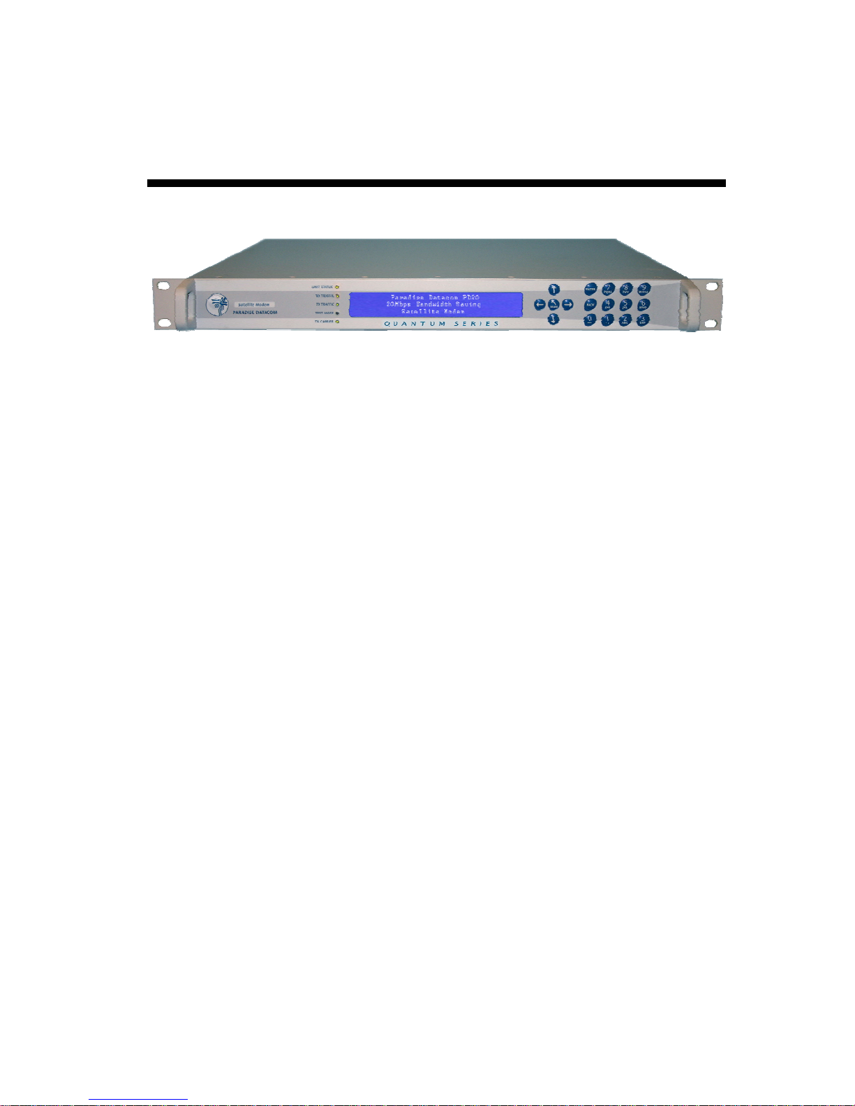
1.15 Front Panel
Modem Front Panel
The front panel comprises:
• LEDs (light emitting diodes) that provide basic modem status
• A LCD (liquid crystal display) display that acts as the main user interface
• A keypad for alphanumeric entry and menu selection.
1.15.1 LEDs
The five LEDs display warning and fault information as shown below.
Unit Status
Rx Traffic
Tx Traffic
Test Mode
Tx Carrier
Off Red
Not used
Rx fault or Rx
disabled
Tx fault or Tx
disabled
Normal mode
Carrier muted
Unit fault
Not used Not used
Not used Not used
Not used
Not used
Front Panel LED Status
mbe
Not used
Test mode
1-for-1 standby Carrier active
Green
Unit OK
Rx OK
Tx OK
Not used
1.15.2 LCD Display
The backlit LCD is a graphical display formatted to give three lines of 40 text characters
and is highly legible even in strong ambient light. The right hand side of the display is
reserved for icons that indicate status information pertinent to keypad operation. These
icons are listed below. The contrast is adjustable and the backlight can be switched off or
on.
6-13
Quantum and Evolution Series Installation and Operating Handbook
Local (front panel) control LOC
Remote control REM
Keyboard locked
Help screen
Numeric entry mode
Alphabetic entry mode
Modem is on a Tx Edit screen
Modem is on an Rx Edit screen
Front Panel LCD Icons
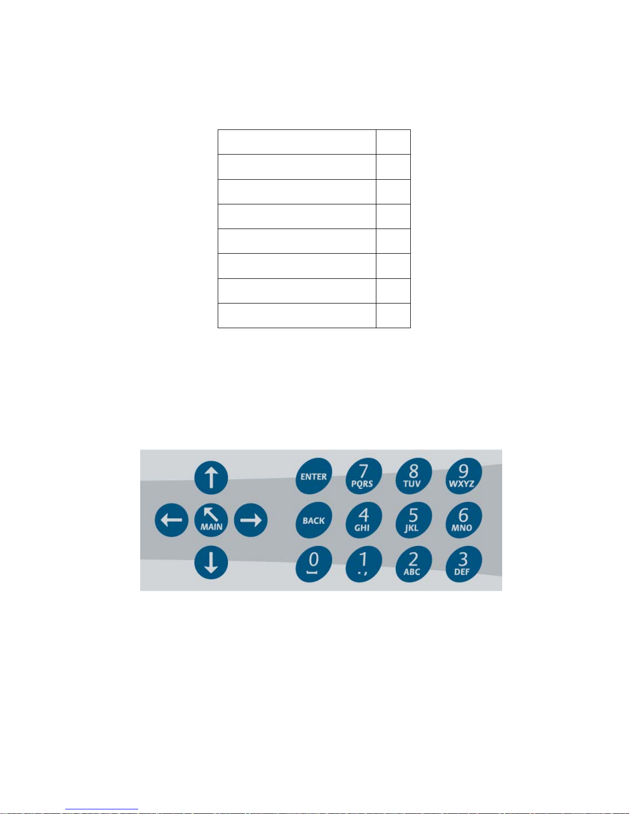
1.15.2.1 Keypad
The keypad (see the diagram below) is based on a sealed tactile membrane and allows
full alphanumeric entry and navigation using arrow keys.
±
?
123
Abc
Tx
Rx
Front Panel Keypad
6-14
Quantum and Evolution Series Installation and Operating Handbook
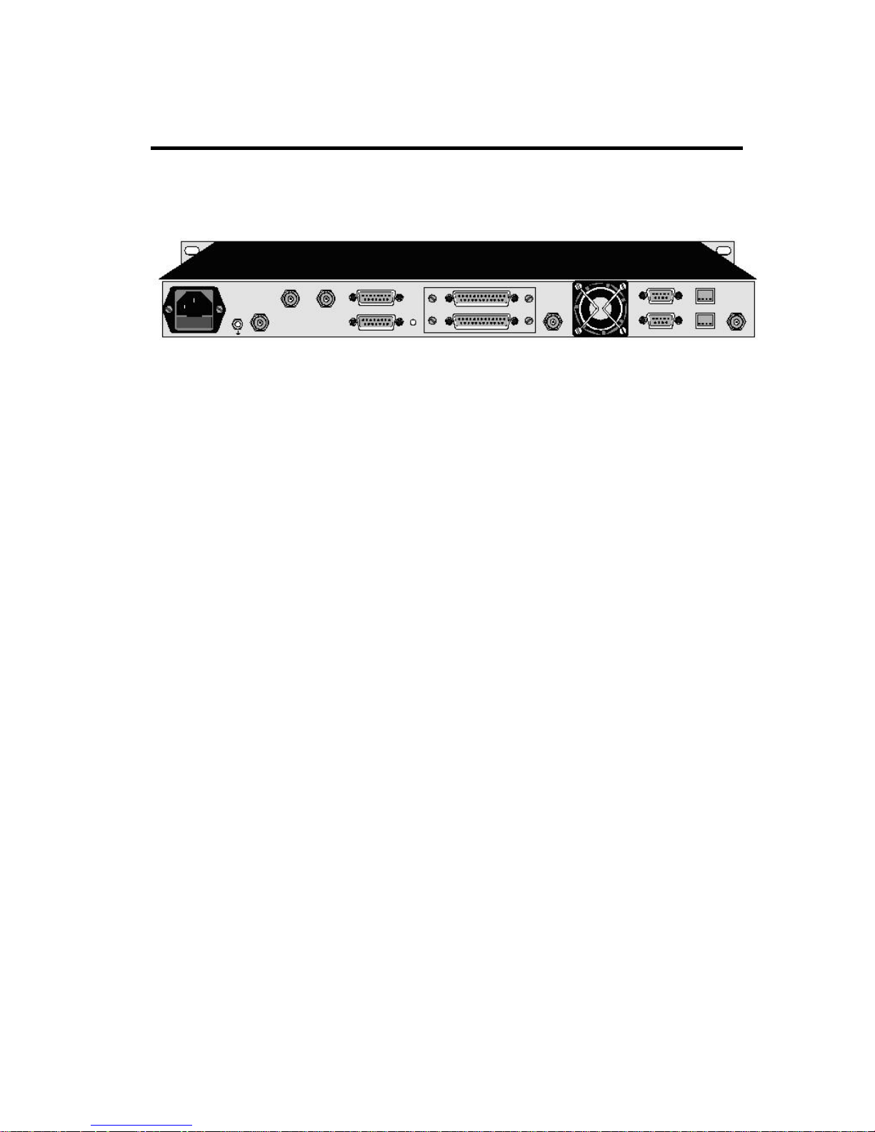
1.16 Rear Panel
The rear panel, shown below, provides a full set of terrestrial and satellite data interfaces.
Modem Rear Panel
Full connector pinouts are given in Chapter 11. From left to right, the rear panel consists of:
IEC Mains Power Connector/Voltage Selector/Fuse
The modem is designed to operate from a mains AC supply of 100-240V (-10%/+6%, i.e.
90V to 254V at the connector), 1 - 0.4A, 47 to 63Hz. The IEC connector incorporates two
fuses, independently fusing both live and neutral lines. Access to the fuses is provided by a
slide-out tray. Both fuses are standard 20mm type, rated T3.15A, of the slow-blow (timedelay) type. ALWAYS REPLACE THE FUSE WITH ONE OF THE SAME TYPE AND
RATING.
Chassis Ground Stud
This is an M4 stud for connecting a safety earth conductor directly to the chassis of the unit.
Tx IF Output Option
This connector is a BNC female and can be used in either 50Ω or 75Ω-impedance mode.
The output power level can be varied from 0dBm to -25dBm.
G.703 BNCs
Two optional BNC connectors may be fitted. These provide an unbalanced G.703 interface.
Tx L-band Output Option
This connector is an N-type female and is of 50 Ω impedance. The output power level can
be varied from –5dBm to –30dBm.
6-15

Quantum and Evolution Series Installation and Operating Handbook
Alarms and AGC Connector
This is a 15-pin male 'D' type connector that provides access to the four form `C' relay
contacts that indicate alarm conditions. There is also an AGC output.
The alarm relays have the following default definitions:
Unit Fault: A unit fault exists, i.e. an equipment failure.
Tx Traffic Prompt: Tx traffic fault exists.
Rx Traffic Prompt: Rx traffic fault exists.
Deferred Alarm: One of the following conditions exists:
• The receive BER is greater than the user defined threshold.
• The receive Eb/No is lower than the user defined threshold.
• Buffer slips are more frequent than the user set threshold.
• A backward alarm is being received from either the satellite or
terrestrial ports.
Async ESC Connector
This is a 15-pin `D` female connector. When the IDR option is not fitted, it provides an
RS232/RS422/RS485 asynchronous port for either the high rate Async ESC facility (for
IBS/SMS or Closed Net Plus ESC services) or the IBS/SMS `low rate Intelsat oversampled
ESC facility` (which is configured as the Aux data channel on the modem). When the IDR
option is fitted, separate ports for the ESC and Aux channels on the IDR card are activated
and ESC/Aux access on this async connector is disabled. This connector also provides
the input port for an RS422-compatible Station Clock.
On-line LED
This LED mirrors the front panel Tx Carrier LED, so that from the rear of the equipment the
operator can tell if the carrier is off and which unit of a 1:1 pair is the offline unit.
Terrestrial Interface Connectors
There are two terrestrial interface connector positions. Supported interface cards include
EIA530, LVDS, balanced G.703 (unbalanced G.703 is provided via a third interface
position), HSSI, Quad E1, IP Traffic and Eurocom D1.
The IDR option is fitted in the upper interface position with the terrestrial interface in the
lower position.
If the G.703 option is fitted, then balanced G.703 supporting T1, E1, T2, E2, T3 and E3
modes is available. Balanced-operation T1(1544kbps, 100Ω), E1 (2048kbps, 120Ω) and
T2 (6136kbps, 110Ω) is provided on the EIA530 `D` type connector when G.703 is selected
in addition to RS422, V.35 and RS232 EIA530 modes. Unbalanced-operation E1
(2048kbps, 75Ω), T2 (6136kbps, 75 Ω), E3 (34376kbps, 75Ω) and T3 (44376kbps, 75Ω)
requires the use of the two BNC connectors in interface position 3. The line impedance and
all other parameters are selected via software. The software also selects what happens to
the G.703 port when power is removed. Either the G.703 ports can be set to go high
impedance (used in 1:1 redundancy operation) or they can be configured to loop the G.703
6-16

Quantum and Evolution Series Installation and Operating Handbook
input back to the output (typically used when Drop/Insert is in operation and the same PCM
bearer is cascaded through several modems).
ESC and Aux Connector
This connector is fitted as part of the IDR option and provides access to:
• Four backward alarm form `C` outputs and four backward alarm inputs, together
with an Rx summary alarm signal for direct connection to the backward alarm
inputs. These are used in IDR mode.
• Two audio ESC ports (4-wire 600Ω, +7 to -16dBm). In addition to normal IDR ESC
operation these ports may also be used in IBS modes to generate a 64kbps IBS
carrier comprised of two 32kbps ADPCM audio channels or a 128kbps IBS carrier
comprised of 64kbps data (from the main data interface of the modem) plus two
32kbps ADPCM audio channels. This is an emulation of the most popular modes of
the P1348/P1448 voice/data MUX card often used in SNG applications.
• An RS232/RS422/RS485 port for synchronous/asynchronous ESC traffic. This port
replaces the shared ESC/Aux access via the Async ESC connector on the main
unit. It is used to provide access to the 8kbps synchronous IDR ESC channel. If the
Async ESC feature is available then this port provides both asynchronous access to
the 8kbps channel and a high rate asynchronous ESC in IBS/SMS and Closed
network plus ESC services.
• An RS232/RS422 port for synchronous/asynchronous Aux traffic. This port replaces
the shared ESC/Aux access via the Async ESC connector on the main unit. The
Aux port provides 32 or 64kbps access to the IDR overhead in place of one or both
of the IDR 32kbps ADPCM audio ESC channels. In IBS/SMS, this port may be
configured to provide either the IBS `low rate INTELSAT oversampled ESC facility`
or a higher rate synchronous channel within the IBS/SMS overhead.
Rx IF Input Option
This is a BNC female connector and can be used in either 50Ω or 75Ω impedance mode.
The carrier signal level presented at the input of the modem should be in the range -60dBm
to -30dBm. A level of -45dBm is recommended. The maximum composite power level that
should be applied to this port is 30dB above the desired carrier, up to a maximum of 0dBm.
Rx L-band Input Option
This is an N-type female connector of 50Ω impedance. The carrier signal level presented
at the input of the modem should be in the range -20dBm to -70dBm. A level of -45dBm is
recommended. The maximum composite-to-wanted power level that can be applied to
this port with no implementation loss is +35dBc, with a maximum composite power level
of +10dBm.
Fan
There is a fan that runs at all times while the unit is powered. This draws air in from the
sides and expels to the rear. The side vents must not be blocked.
1:1 Redundancy Connector
The Modem has a built-in 1-for-1 redundancy-controller that connects to the corresponding
port of another modem via a 9-pin male 'D' type connector. A 1:1 redundancy system
requires two modems, a 1:1 control cable between the two redundancy connectors, a data
6-17

Quantum and Evolution Series Installation and Operating Handbook
split (`Y`) cable and passive splitters/combiners for the IF ports. An overview of 1-for-1
operation is provided in Section 8.4.
Remote M&C Connector
This is a 9-pin female 'D' type connector. The modem supports the Paradise Universal
Protocol (PUP) as specified in the document ‘Remote M&C Specification for Quantum and
Evolution Series Satellite Modems’. The electrical interface can be selected between
RS232 (for direct-to-PC applications) and RS485 (for multidrop applications). The Remote
M&C port may be linked under software control to the Async ESC port for distant end
remote M&C control over satellite.
Ethernet IP and M&C Connectors
There are two RJ45 auto-sensing 10/100Mbps Ethernet connections. These support both
half-duplex and full-duplex operation. One of these can be switched to the main modem
traffic channel for sending and receiving TCP/IP data over satellite, while the other is for
remote M&C. M&C control can be via the Simple Network Management Protocol (SNMP),
an embedded web server that sends web pages to a web browser, a Telnet-style terminal
emulation application or via TCP packets that encapsulate Paradise Universal Protocol
(PUP) commands. Although the two connectors are labelled for IP traffic and remote M&C
respectively, they are in fact interchangeable since the modem acts as an Ethernet bridge
(satellite IP traffic and modem M&C messages can use the same single connector if
preferred). It is also possible to change the configuration so that the M&C port is removed
from the bridge, which may benefit security in some circumstances where it is important to
separate the M&C and IP traffic streams.
An M&C IP address, subnet mask and default gateway may be set in the modem. When
using TCP acceleration and the M&C interface does not form part of the Ethernet bridge,
then a traffic IP address must be set in addition. Note that the modem is not configured for
auto-sense of the cable type and consequently either a straight or crossover (patch) cable
may be required, depending on the equipment being connected (typically a straight cable is
required when connecting direct to a PC and a crossover cable is required when
connecting to a hub or switch). Setting up IP addresses is covered in more detail in Section
8.12.
Station Clock
This connector is a 75Ω BNC female that accepts a 1-10MHz signal, either a square
wave of >1V p/p (e.g. a G.703 para. 10 `synchronising clock`) or a sinusoid at a power
level of 0dBm or greater. An alternative Station Clock signal at RS422 interface levels can
be applied to the Async ESC connector. Either signal can be used by the modem as a
reference for the receive output clock (the Station Clock does not have to be the same
rate as the data as an internal PLL converts between rates). In addition, if the Rx
Clocking is set to use the Station Clock and the Tx Clocking is set to Rx, then the Station
Clock also sources the internally generated Tx Clock (Tx and Rx data rates are
independent). If a 10MHz signal is applied, this signal may also be used in place of the
internal reference for the Tx and Rx IF synthesisers.
6-18
 Loading...