

Teledyne EV71YC1MCL2010-BA0, EV71YC1MCL4005-BA0, EV71YC1MCL4005-BA3, EV71YC1MCL4005-BA2, EV71YC1MCL2010-BA1 User Manual
...
UNIIQA+ Family
Line Scan Simplicity
e2v.com/cameras
USER MANUAL
UNIIQA+ MONOCHROME

USER MANUAL UNIIQA+ MONOCHROME – REV J – 05/2017
P A G E | 2
Table of Contents
1 Camera Overview ................................................................................................................ 5
1.1 Features ............................................................................................................................................. 5
1.1 Key Specifications .............................................................................................................................. 5
1.2 Description......................................................................................................................................... 7
1.3 Typical Applications ........................................................................................................................... 7
1.4 Models ............................................................................................................................................... 7
2 Camera Performances ......................................................................................................... 8
2.1 Camera Characterization ................................................................................................................... 8
2.2 Image Sensor ..................................................................................................................................... 9
2.3 Response & QE curves ..................................................................................................................... 10
2.3.1 Quantum Efficiency ................................................................................................................. 10
2.3.2 Spectral Response Curves ........................................................................................................ 10
3 Camera Hardware and Interface ........................................................................................ 11
3.1 Mechanical Drawings....................................................................................................................... 11
3.2 Input/output Connectors and LED .................................................................................................. 12
3.2.1 Power Connector ..................................................................................................................... 13
3.2.2 Consumption and Inrush Current ............................................................................................ 13
3.2.3 Status LED Behaviour ............................................................................................................... 14
3.2.4 CameraLink Output Configuration........................................................................................... 14
4 Standard Conformity ......................................................................................................... 15
4.1 CE Conformity .................................................................................................................................. 15
4.2 FCC Conformity ................................................................................................................................ 15
4.3 RoHS / Chinese RoHS ....................................................................................................................... 15
4.4 GenICam / GenCP ............................................................................................................................ 15
5 Getting Started .................................................................................................................. 16
5.1 Out of the box .................................................................................................................................. 16
5.2 Setting up in the system .................................................................................................................. 16
6 Camera Software Interface ................................................................................................ 17
6.1 Control and Interface ...................................................................................................................... 17
6.2 Serial Protocol and Command Format ............................................................................................ 18
6.2.1 Syntax ...................................................................................................................................... 18
6.2.2 Command Processing .............................................................................................................. 18
6.2.3 GenCP Compliance .................................................................................................................. 18

USER MANUAL UNIIQA+ MONOCHROME – REV J – 05/2017
P A G E | 3
6.2.4 Error code table ....................................................................................................................... 19
7 Camera Commands ........................................................................................................... 20
7.1 Device Information .......................................................................................................................... 20
7.2 Device Privilege, Status and Reboot ................................................................................................ 21
7.3 Communication and Firmware version ........................................................................................... 23
7.4 Image Format .................................................................................................................................. 24
7.5 Image Control .................................................................................................................................. 29
7.6 Acquisition Control .......................................................................................................................... 30
7.7 Gains and Offsets ............................................................................................................................. 32
7.8 Flat Field Correction ........................................................................................................................ 35
7.8.1 Activation, Auto-Adjust ........................................................................................................... 36
7.8.2 Automatic Calibration and LowPass Filter ............................................................................... 37
7.8.3 Manual Flat Field Correction ................................................................................................... 41
7.9 Save & Restore FFC and Configuration User set .............................................................................. 43
7.9.1 Save & Restore FFC .................................................................................................................. 43
7.9.2 Save & Restore Settings ........................................................................................................... 44
APPENDIX ................................................................................................................................ 45
Appendix A. Test Patterns ........................................................................................................ 46
A.1 4k Pixels, 12bits ..................................................................................................................................... 46
A.2 2k Pixels, 12bits ..................................................................................................................................... 46
A.3 1k Pixels, 12bits ..................................................................................................................................... 47
A.4 0.5k Pixels, 12bits .................................................................................................................................. 47
Appendix B. Timing Diagrams ................................................................................................... 48
B.1 Synchronization Modes with Variable Exposure Time .......................................................................... 48
B.2 Synchronisation Modes with Maximum Exposure Time ....................................................................... 49
B.3 Timing Values ........................................................................................................................................ 50
Appendix C. CameraLink Data Cables ........................................................................................ 51
C.1 Choosing the Cable ................................................................................................................................ 51
C.2 Choosing the Data Rate ......................................................................................................................... 52
C.2.1 High Speed Models ......................................................................................................................... 52
C.2.2 Essential Models ............................................................................................................................. 53
Appendix D. Lens Mounts ......................................................................................................... 55
D.1 F-Mount................................................................................................................................................. 55
F Mount: (Part number EV50-MOUNT-F) .................................................................................................... 55
D.2 C-Mount ................................................................................................................................................ 56

USER MANUAL UNIIQA+ MONOCHROME – REV J – 05/2017
P A G E | 4
Appendix E. CommCam Connection .......................................................................................... 57
Appendix F. Revision History .................................................................................................... 59
USER MANUAL UNIIQA+ MONOCHROME – REV J – 05/2017
P A G E | 5
1 Camera Overview
1.1 Features
CMOS Monochrome LineScan Sensors:
4096 pixels, 5x5µm or 4096 pixels, 5x10µm (Versatile models Only)
2048, 1024 or 512 pixels, 10x10µm
Interface : CameraLink® (Base or Medium/Full)
Line Rate :
Up to 40 kl/s for the Base Version
Up to 100 kl/s for the High-Speed Version
Line rate limited at 40kl/s in 12bits for all models
Data Rate :
42.5MHz, 60MHz and 85MHz in 1 or 2 Channels for Base version
42.5MHz, 60MHz and 85MHz in Base, Medium, Full or Full+ (Deca) for the High Speed Version
Bit Depth : 8, 10 or 12bits
Flat Field Correction
Contrast Expansion
Power Supply : 10 – 15V. PoCl Compliant.
Low Power Consumption : < 3.5W
M42x1 Native and F-Mount, C-Mount adapters available
GenCP Compliant (xml file embedded)
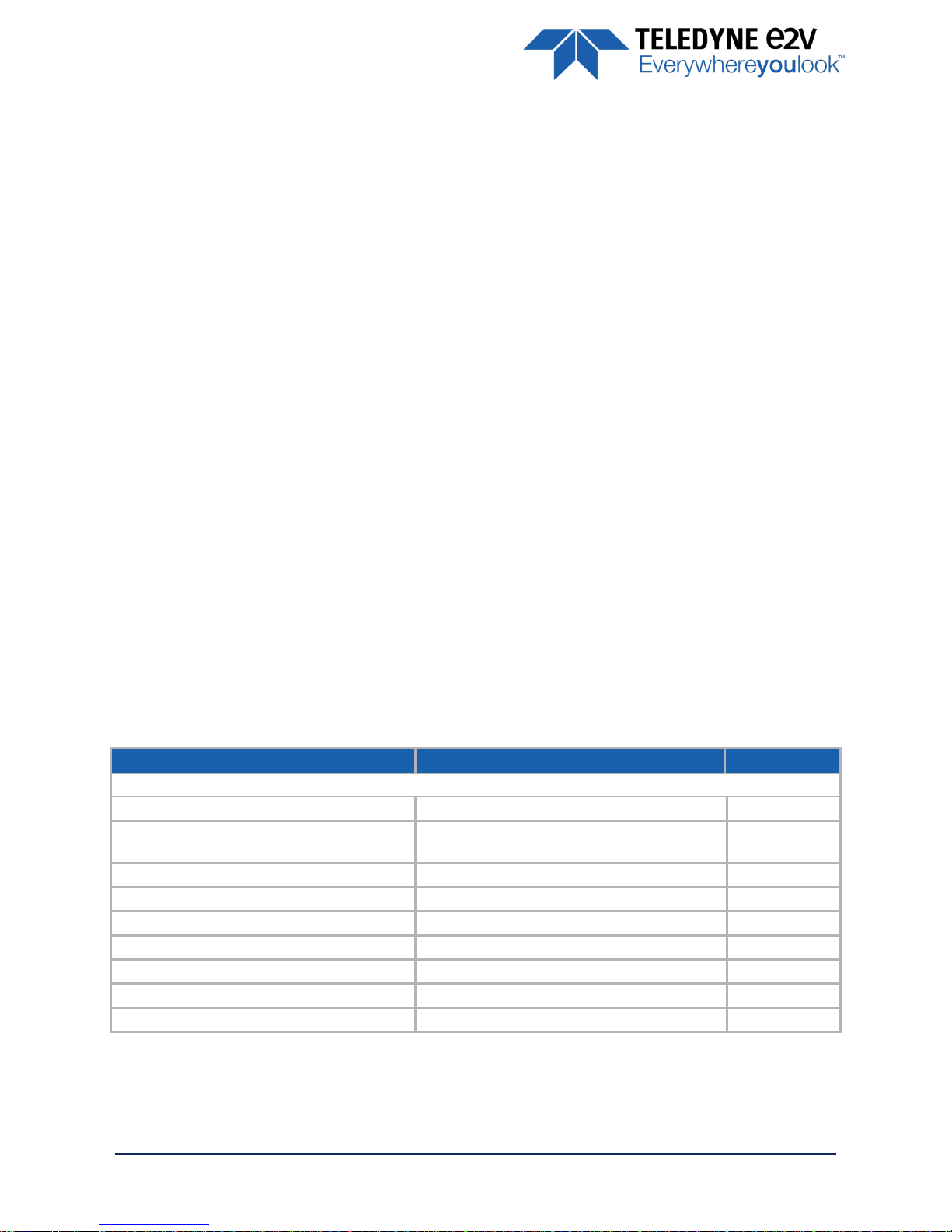
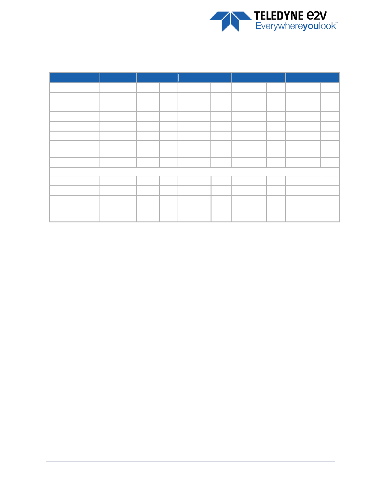
1.1 Key Specifications
(*)
Versatile Models Only
Characteristics
Typical Value
Unit
Sensor Characteristics at Maximum Pixel Rate
Resolution
4096 2048 1024 512
Pixels
pixel size
5 x 5 10 x 10 10 x 10 10 x 10
5 x 10
(*)
µm
Max Line Rate (Essential Version)
CameraLink® Base
20 40 40 40
kHz
Max Line Rate (High Speed version)
CameraLink® Base (8 or 10bits) (2)
40 80 100 100
kHz
CameraLink® Base or Medium (12bits) (3)
40 40 40 40
kHz
CameraLink® Medium (8/10bits) or Full (8bits)(2)
80 100 100 100
kHz
CameraLink® Deca (8bits)(4)
100 100 100 100
kHz
USER MANUAL UNIIQA+ MONOCHROME – REV J – 05/2017
P A G E | 6
Notes :
(*) High Dynamic / High Response. : High dynamic with the Use of Multi-Column Gain 1/2
(**) Teledyne-e2v norm: more severe than EMVA 1288 Standard
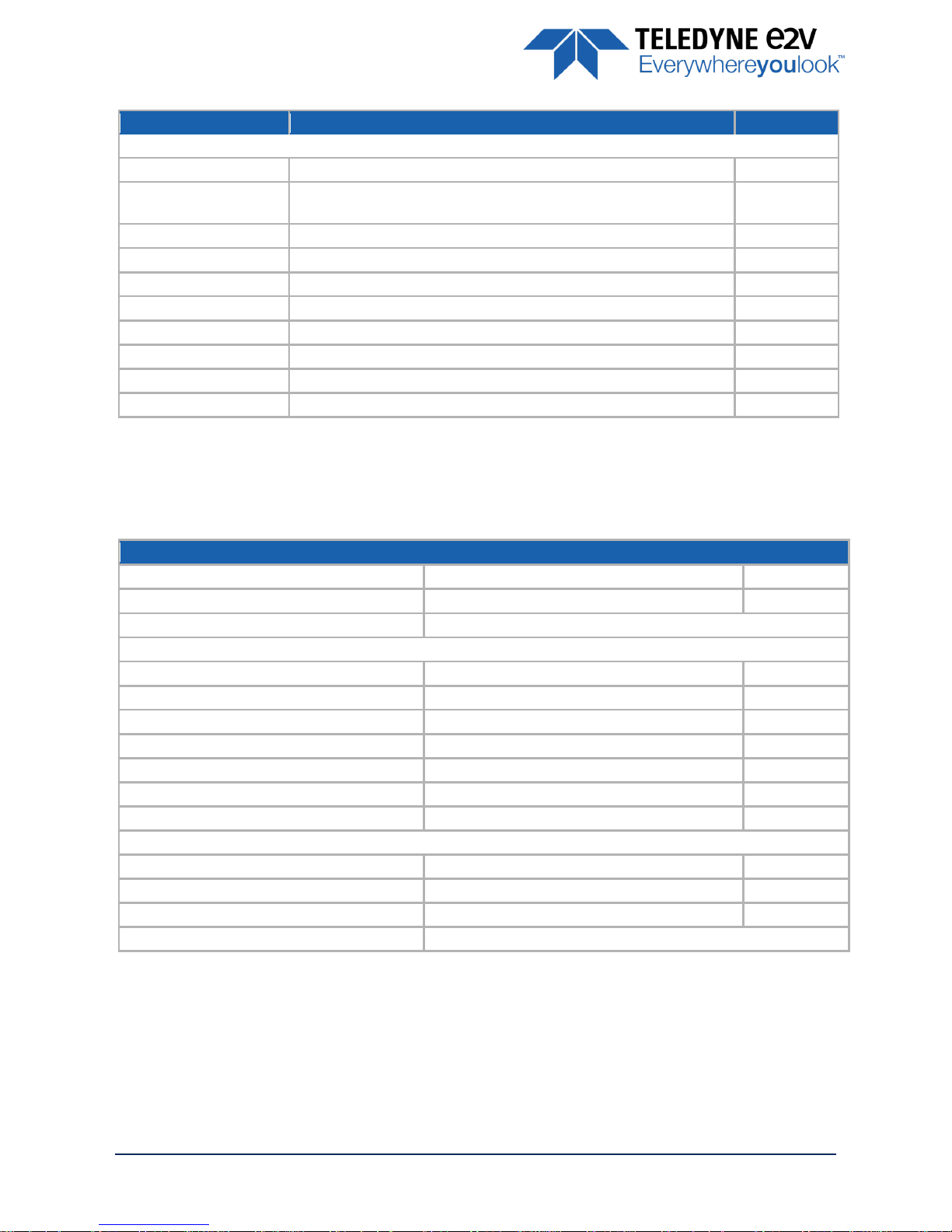
Characteristics
Typical Value
Unit
Radiometric Performance at Maximum Pixel Rate and minimum camera gain
Bit depth
8, 10 and 12
Bits
Resolution
4096 4096 2048 1024 512
5 x 5 5 x 10 10 x 10 10 x 10 10 x 10
Pixels
Response (Peak at 565nm)
162 81 162/324
(*)
162/324
(*)
162/324
(*)
LSB/(nJ/cm²)
Camera Gain
5,9 5,9 11.1 11.1 11.1
e-/LSB
12bits
Full Well Capacity
23,7 23,7 47.3/23.7
(*)
47.3/23.7
(*)
47.3/23.7
(*)
Ke-
Response non linearity
1 1 2
(**)
2
(**)
2
(**)
%
Readout Noise
7,5 7,5 10.6 10.6 10.6
e-
Dynamic range
70 70 73/67
(*)
73/67
(*)
73/67
(*)
dB
SNR Max (3/4 Sat)
42 42 45/41.8
(*)
45/41.8
(*)
45/41.8
(*)
dB
PRNU HF Max
3
%
Functionality (Programmable via Control Interface)
Analog Gain
Up to 12 (x4)
dB
Offset
-4096 to +4096
LSB
Trigger Mode
Timed (Free run) and triggered (Ext Trig, Ext ITC) modes
Mechanical and Electrical Interface
Size (w x h x l)
60 x 60 x 33.65
mm
Weight
<150
g
Lens Mount
F, C and M42x1 (on the Front Face)
-
Sensor alignment ( see chapter 2.1 )
±100
µm
Sensor flatness
50
µm
Power supply
Single 10 DC to 15 DC
V
Power dissipation
< 3,6 PoCL compliant
W
General Features
Operating temperature
0 to 50 (front face), 70 (internal)
°C
Relative Humidity for Operation
85% % Storage temperature
-40 to 70
°C
Regulatory
CE, FCC , Reach, RoHS and Chinese RoHs compliant
USER MANUAL UNIIQA+ MONOCHROME – REV J – 05/2017
P A G E | 7
1.2 Description
Teledyne-e2v’s UNiiQA+ line scan cameras family has been specifically designed to overcome the
limitations of your current inspection system: make cost savings, improve your throughput, inspect larger
areas or identify smaller defects.
Three UNiiQA+ product ranges are offered:
UNiiQA+ Essential: low speed cameras for cost effective equipment or with modest speed requirement
UNiiQA+ High-Speed: high speed cameras to help improve the performance of your system
The UNiiQA+ family has also been designed to be highly modular to enable engineers to reuse the same
camera in multiple equipment, simplify logistics and reduce development cycle time. All UNiiQA+ cameras
feature Teledyne-e2v’s proprietary CMOS sensors : a single line of highly sensitive pixels of either 5µm or
10µm size.
1.3 Typical Applications
On-line quality control
Raw material inspection (plastic film, glass, wood…)
Print and paper inspection
Sorting
Food sorting (Belt sorting, Lane sorting, Free fall sorting)
Parcel and postal sorting
Barcode reading
1.4 Models
Camera Part Number
Description
Details
UNIIQA+
Essential
EV71YC1MCL4005-BA2
Versatile Base CameraLink
4k pixels 5x5µm up to 20kHz
2k, 1k and 0,5k pixels 10x10µm up to 40kHz
EV71YC1MCL4005-BA0
4k Pixels Base CameraLink
4k pixels 5x5µm up to 20kHz
EV71YC1MCL2010-BA0
2k pixels Base CameraLink
2k pixels 10x10µm up to 40kHz
UNIIQA+
High Speed
EV71YC1MCL4005-BA3
Versatile Full CameraLink
4k pixels 5x5µm up to 100kHz
2k, 1k and 0,5k pixels 10x10µm up to 100kHz
EV71YC1MCL4005-BA1
4k Pixels Full CameraLink
4k pixels 5x5µm up to 100kHz
EV71YC1MCL2010-BA1
2k pixels Full CameraLink
2k pixels 10x10µm up to 100kHz
USER MANUAL UNIIQA+ MONOCHROME – REV J – 05/2017
P A G E | 8
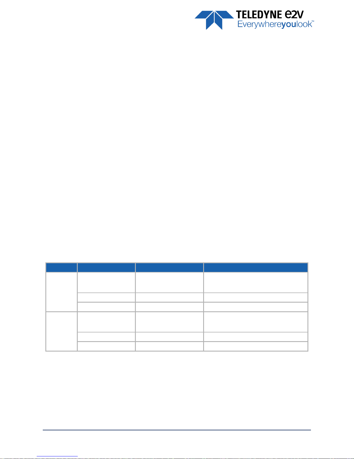
2 Camera Performances
2.1 Camera Characterization
Unit
4k x 5µm
2k x 10µm
1k x 10µm
0,5k x 10µm
Typ.
Max
Typ.
Max
Typ.
Max
Typ.
Max
Dark Noise RMS
LSB
1.3 - 1.08 - 1.08 - 1.08
-
Dynamic Range
dB
70 - 73/67
(*)
-
73/67
(*)
-
73/67
(*)
-
Readout Noise
e-
7.5 - 10.6 - 10.6 - 10.6
-
Full Well Capacity
Ke-
23.7
-
47.3/23.7
(*)
-
47.3/23.7
(*)
-
47.3/23.7
(*)
-
SNR (3/4 Sat)
dB
42.5
-
45/41.8
(*)
-
45/41.8
(*)
-
45/41.8
(*)
-
Peak Response
(660nm)
LSB/ (nJ/cm2)
81 - 162/324
(*)
-
162/324
(*)
-
162/324
(*)
-
Non Linearity
%
1 - 2 - 2 - 2
-
Without Flat Field Correction :
FPN rms
LSB
0.41 1 0.36 1 0.36 1 0.36 1 FPN pk-pk
LSB
2.7 6 2.2 6 2.2 6 2.2
6
PRNU hf (3/4 Sat)
%
0.11 1 0.07 1 0.07 1 0.07
1
PRNU pk-pk
(3/4 Sat)
%
0.8 3 0.5 3 0.5 3 0.5
3
Note :
(*)High Dynamic / High Response. : High dynamic with the Use of Multi-Column Gain 1/2
Test conditions :
Figures in LSB are for a 12bits format.
Measured at Max Exposure Time and Nominal Gain (No Gain)
Maximum data rate
Stabilized temperature 30/40/55 °C (Room/Front Face/Internal)
SNR Calculated at 75% Saturation with minimum Gain.
USER MANUAL UNIIQA+ MONOCHROME – REV J – 05/2017
P A G E | 9
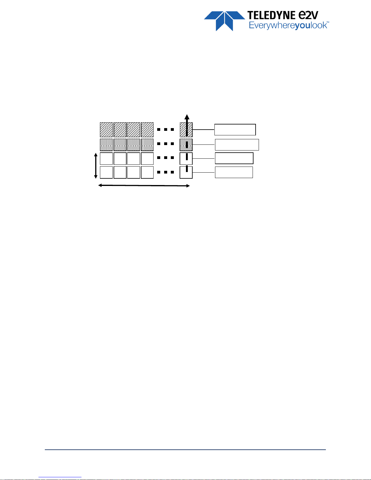
2.2 Image Sensor
The Uniiqa+ sensor is composed of one pair of sensitive lines of 4096 pixels of 5µm square.
Each pixel on the same column uses the same Analog to Digital Column converter (ADC Column).
This structure allows several definitions :
4k pixels 5x5µm
2k Pixels 10x10µm by binning of 4 pixels
Then, 1k or 0,5k 10x10µm are achieved by applying an ROI on the centre of the sensor.
ADC Column
Memory Node
Pixel Line A
Pixel Line B
4096 Pixels 5x5µm
USER MANUAL UNIIQA+ MONOCHROME – REV J – 05/2017
P A G E | 10
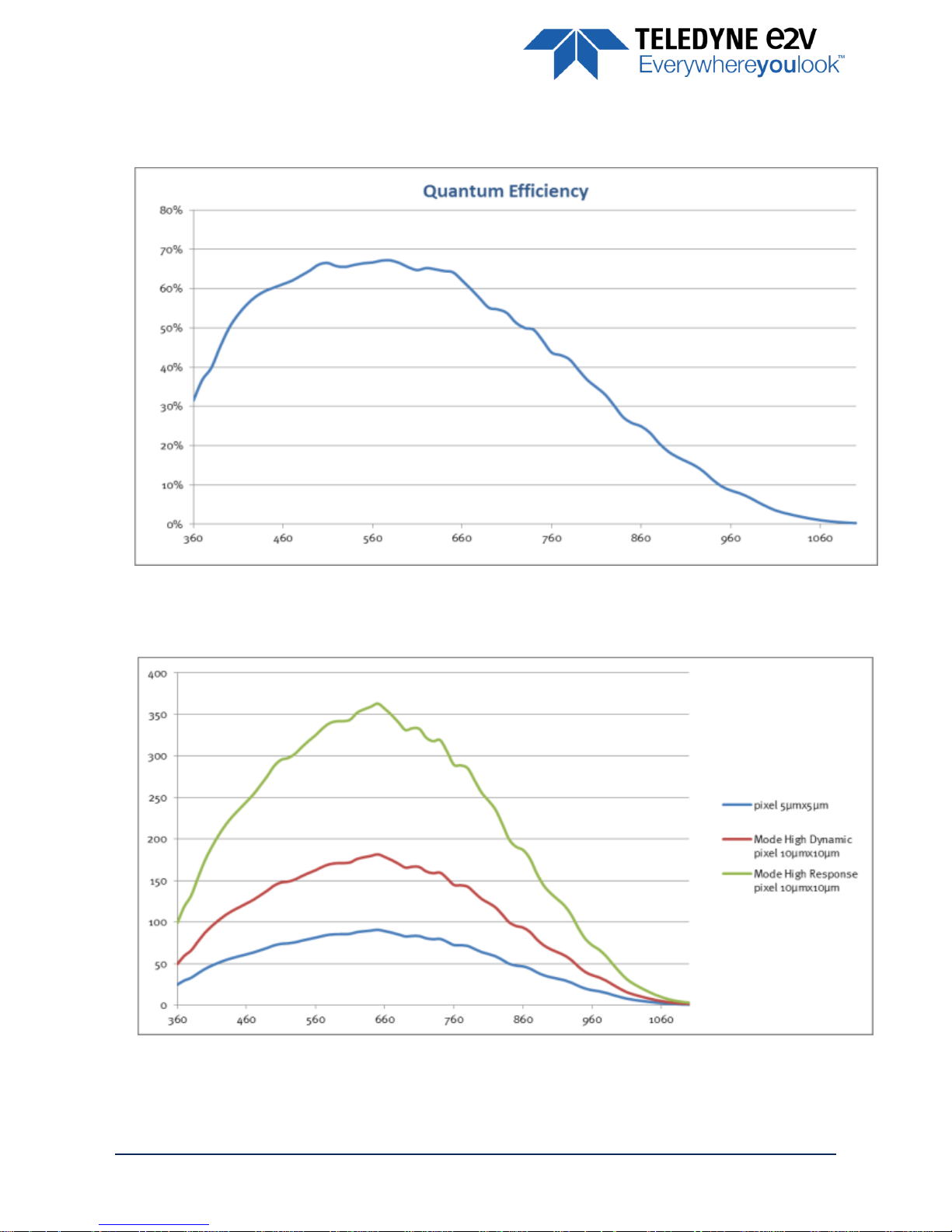
2.3 Response & QE curves
2.3.1 Quantum Efficiency
2.3.2 Spectral Response Curves
(*) High Dynamic / High Response. : High dynamic with the Use of Multi-Column Gain 1/2
USER MANUAL UNIIQA+ MONOCHROME – REV J – 05/2017
P A G E | 11
3 Camera Hardware and Interface
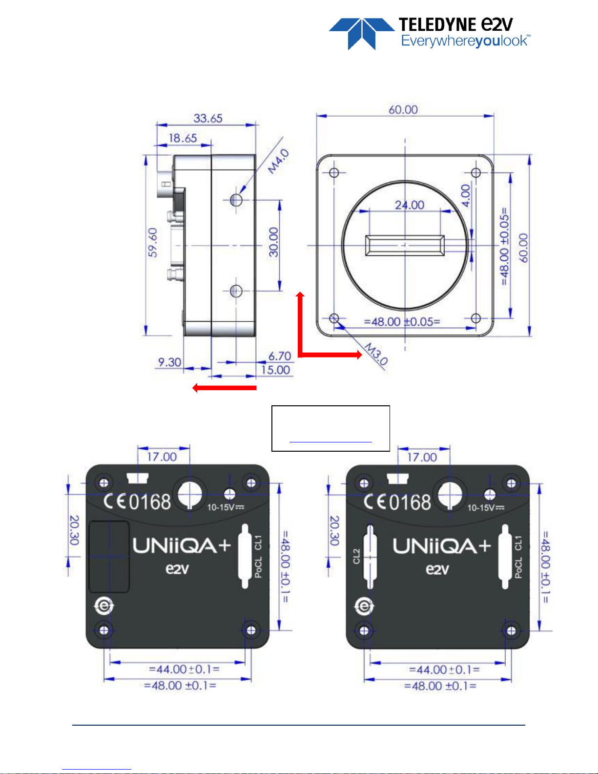
3.1 Mechanical Drawings
Essential Model High Speed Model
The Step file is available
on the web :
www.e2v.com/cameras
X Y Z
USER MANUAL UNIIQA+ MONOCHROME – REV J – 05/2017
P A G E | 12
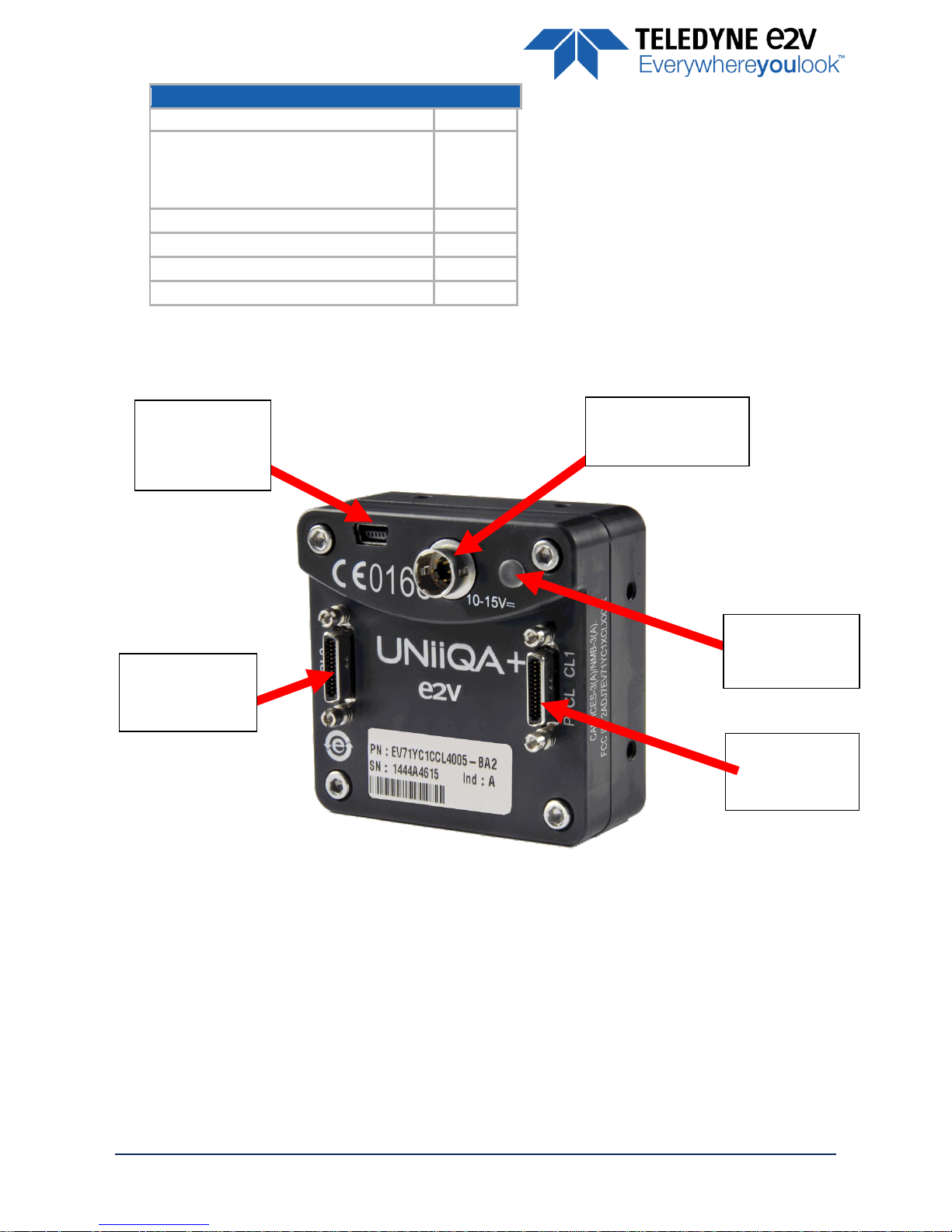
3.2 Input/output Connectors and LED
Sensor alignment
Z = -10.3 mm
±100µm
X = 19.76 mm (4k 5µm)
X = 19.76 mm (2k 10µm)
X = 24.88 mm (1k 10µm)
X = 27.44 mm (0.5k 10µm)
±100 µm
Y = 30 mm
±100 µm
Die flatness
50 µm
Rotation (X,Y plan)
±0.3°
Parallelism
50µm
CameraLink
Connector CL1
(PoCL)
Power Connector :
10-15V DC
Multi-Coloured
LED for Status
and diagnostic
CameraLink
Connector CL2
(High Speed ver.
USB Connector
For Firmware
upgrade
USER MANUAL UNIIQA+ MONOCHROME – REV J – 05/2017
P A G E | 13
3.2.1 Power Connector
Camera connector type: Hirose HR10A-7R-6PB (male)
Cable connector type: Hirose HR10A-7P-6S (female)
Signal
Pin
Signal
Pin
PWR
1
GND 4 PWR
2
GND 5 PWR
3
GND
6
Power supply from 10 to 15v
Power 3,5W max with an typical inrush current peak
of
0,32A
during power up
3.2.2 Consumption and Inrush Current
Typical current/Power during the grab (possible variation : +/- 5%)
Power Time : Max 3s (Green Light)
Camera supply
(Max Speed)
Supply 10V
Supply 12V
Supply 15V
I(mA)
I(mA)
I(mA)
P(W)
I(mA)
P(W)
Essential
309
3.09W
257
3.09W
209
3.14W
High Speed
314
3.14W
261
3.14W
212
3.19W
Inrush current : pic
2nd pic
Established current
USER MANUAL UNIIQA+ MONOCHROME – REV J – 05/2017
P A G E | 14
3.2.3 Status LED Behaviour
After less than 2 seconds of power establishment, the LED first lights up in ORANGE. Then after a Maximum
of 3 seconds, the LED must turn in a following colour :
Colour and state
Meaning
Green
and continuous
OK
Green
and blinking slowly
Waiting for External Trigger (Trig1 and/or Trig2)
Red
and continuous
Camera out of order : Internal firmware error
Orange
and Continuous
Camera booting or upgrading
3.2.4 CameraLink Output Configuration
Output Configuration
Channels
Pixels per Channel
Version “Essential”
4k
2k
1k
0,5k
Base : 1 Channel 8/10/12bits
1 x 85MHz
(60/42.5MHz)
1 x 4096
1 x 2048
1 x 1024
1 x 512
Base : 2 Channels 8/10/12bits
2 x 85MHz
(60/42.5MHz)
2 x 2048
2 x 1024
2 x 512
2 x 256
Version “High Speed”
Base : 1 Channel 8/10/12bits
1 x 85MHz
(60/42.5MHz)
1 x 4096
1 x 2048
1 x 1024
1 x 512
Base : 2 Channels 8/10/12bits
2 x 85MHz
(60/42.5MHz)
2 x 2048
2 x 1024
2 x 512
2 x 256
Medium : 4 Channels 8/10/12bits
4 x 85MHz
(60/42.5MHz)
4 x 1024
4 x 512
4 x 256
NR
Full : 8 Channels 8bits
8 x 85MHz
(60/42.5MHz)
8 x 512
8 x 256
NR
NR
Deca : 10 Channels 8bits
10 x 42.5MHz
(60/85MHz)
10 x 409
NR
NR
NR
-
NR : Not required as the fastest speed (100kHz) is already achieved by the precedent output mode with the
lowest data rate (ex : 100kHz is achieved on 512 pixel in base mode with 2 x 42.5Mhz. Medium is not
required, even for 10bits.
USER MANUAL UNIIQA+ MONOCHROME – REV J – 05/2017
P A G E | 15
4 Standard Conformity
The UNIIQA+ cameras have been tested using the following equipment:
A shielded power supply cable
A Camera Link data transfer cable ref. 1MD26-3560-00C-500 (3M), 1SF26-L120-00C-500 (3M)
A linear AC-DC power supply
Teledyne-e2v recommends using the same configuration to ensure the compliance with the following
standards.
4.1 CE Conformity
The UNIIQA+ cameras comply with the requirements of the EMC (European) directive 2004/108/EC (EN
50081-2, EN 61000-6-2).
CE 0168
4.2 FCC Conformity
The UNIIQA+ cameras further comply with Part 15 of the FCC rules, which states that: Operation
is subject to the following two conditions:
This device may not cause harmful interference, and
This device must accept any interference received, including interference that may cause undesired
operation
This equipment has been tested and found to comply with the limits for Class A digital device, pursuant to
part 15 of the FCC rules. These limits are designed to provide reasonable protection against harmful
interference when the equipment is operated in a commercial environment. This equipment generates, uses
and can radiate radio frequency energy and, if not installed and used in accordance with the instruction
manual , may cause harmful interference to radio communications. Operation of this equipment in a
residential area is likely to cause harmful interference
Warning:
Changes or modifications to this unit not expressly approved by the party responsible for
compliance could void the user's authority to operate this equipment.
4.3 RoHS / Chinese RoHS
RoHS per EU Directive 2011/65/EC and WEEE per EU Directive 2002/96/EC
China Electronic Industry Standard SJ/T11364-2006
4.4 GenICam / GenCP
GenICam/GenCP XML Description File, Superset of the GenICam™ Standard Features Naming Convention
specification
V1.5, Camera Link Serial Communication : GenICam™ Generic Control Protocol (Gen CP V1.0)
USER MANUAL UNIIQA+ MONOCHROME – REV J – 05/2017
P A G E | 16
5 Getting Started
5.1 Out of the box
The contains of the Camera box is the following :
One Camera UNIIQA+
There is no CDROM delivered with the Camera : Both User Manual (this document)
and CommCam control software have to be downloaded from the web site : This
ensure you to have an up-to-date version.
Main Camera page : www.e2v.com/cameras
On the appropriate Camera Page (UNIIQA+ Monochrome) you’ll find a download
link
first version of CommCam compliant is indicated in the last Chapter
CommCam download requires a login/password :
Login : commcam
Password : chartreuse
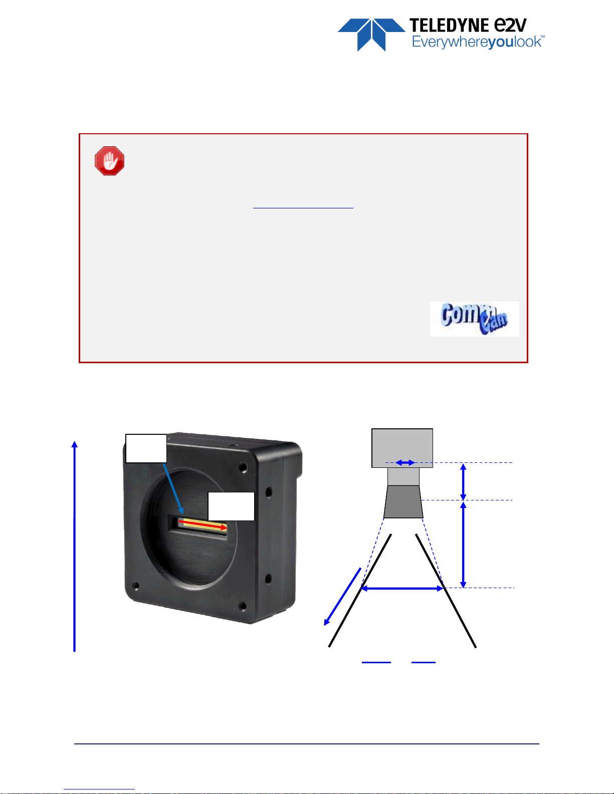
5.2 Setting up in the system
w
f
FOV
L
=
FOV
Focal Plan
Sensor Plan
f
L
w
s
Web
Direction
Readout
order
First
Pixel
USER MANUAL UNIIQA+ MONOCHROME – REV J – 05/2017
P A G E | 17
6 Camera Software Interface
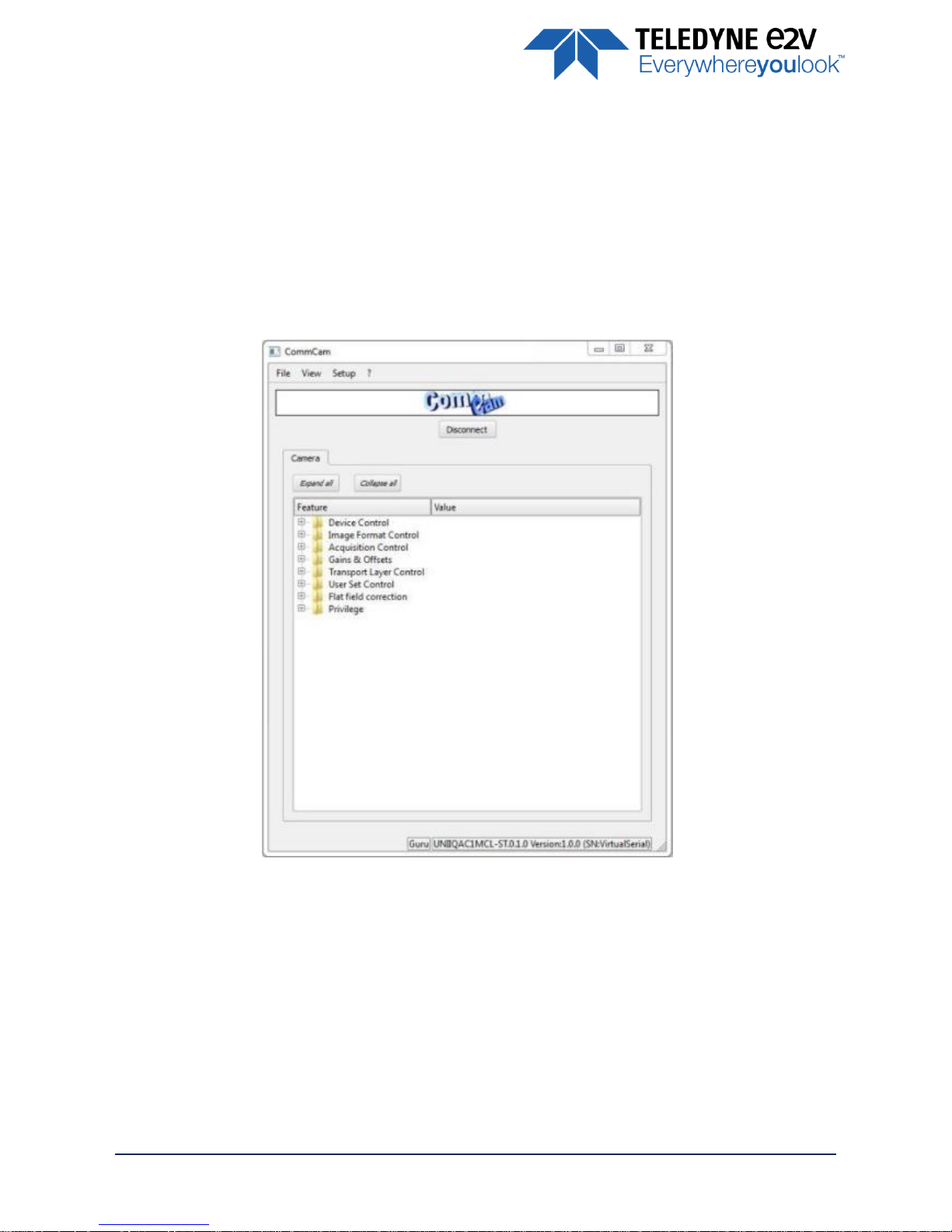
6.1 Control and Interface
As all the Teledyne-e2v Cameras, the UNIIQA+ CL is delivered with the friendly interface control software
COMMCAM.UCL (as “Ultimate Camera Link”) which is based on the GenICam standard
COMMCAM recognizes and detects automatically all the UCL Cameras connected on any transport layers
(Camera Link or COM ports) of your system.
Once connected to the Camera you have an easy access to all its features. The visibility of these features can
be associated to three types of users: Beginner, Expert or Guru. Then you can make life easy for simple
users.
Minimum version of CommCam is
2.4.2
in order to recognize the UNIIQA+ Camera (all versions)

USER MANUAL UNIIQA+ MONOCHROME – REV J – 05/2017
P A G E | 18
6.2 Serial Protocol and Command Format
The Camera Link interface provides two LVDS signal pairs for communication between the camera and
the frame grabber. This is an asynchronous serial communication based on RS-232 protocol.
The serial line configuration is:
> Full duplex/without handshaking
> 9600 bauds (default), 8-bit data, no parity bit, 1 stop bit. The baud rate can be set up to 115200
6.2.1 Syntax
Internal camera configurations are activated by write or readout commands.
The command syntax for write operation is:
w
<command_name> <command_parameters>
<CR>
The command syntax for readout operation is:
r
<command_name>
<CR>
6.2.2 Command Processing
Each command received by the camera is processed:
> The setting is implemented (if valid)
> The camera returns “>”<return code><CR>
The camera return code has to be received before sending a new command.
The camera return code has to be received before sending a new command. Some
commands are longer than the others : Waiting for the return code ensure a good
treatment of all the commands
Without saturating the buffer of the camera.
6.2.3 GenCP Compliance
The camera is compliant with the GenCP standard. It is also still compliant with ASCII command format :
Both types of commands are detailed in the next chapter.
GenCP requires a certain time for the command execution :
Maximum Device Response Time : This register gives the max time for the execution of any command.
Usually it’s set at a value lower than 300ms
If the execution time of the command is greater than 300ms, the camera sends a “pending
acknowledge” command which gives the duration of this command : It can’t be greater than 65536ms
 Loading...