

Page 1
Operator's
Manual
ET-PMT Software
Page 2

Electrical Telecom Pulse Mask Test Software Operator's Manual
© 2013 Teledyne LeCroy, Inc. All rights reserved.
Unauthorized duplication of Teledyne LeCroy documentation materials other than for internal sales and
distribution purposes is strictly prohibited. However, clients are encouraged to distribute and duplicate
Teledyne LeCroy documentation for their own internal educational purposes.
Electrical Telecom Pulse Mask Test and Teledyne LeCroy are trademarks of Teledyne LeCroy, Inc. Other
product or brand names are trademarks or requested trademarks of their respective holders. Information in
this publication supersedes all earlier versions. Specifications are subject to change without notice.
923136 Rev A
October2013
Page 3

Operator's Manual
Contents
Introduction 2
Standards Supported 2
Text Fixtures 3
Set Up Standard Mask Test 4
Add Measurements to Mask Test 6
Create Custom Mask Test 7
Mask Definition Properties 7
923136 Rev A
1
Page 4
Electrical Telecom Pulse Mask Test Software
Introduction
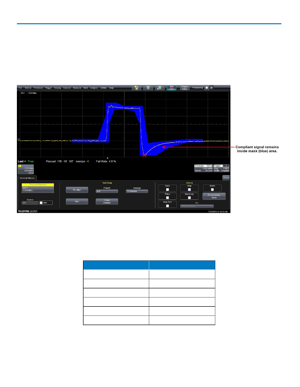
ET-PMT is a software package that measures pulse mask compliance of electrical telecommunications
signals. Pulse mask testing consists of acquiring the given signal in an oscilloscope and comparing the
voltage vs. time waveform to a standard mask. The mask defines regions in V,t space where a compliant
signal must remain.
Below is an example of an ET-PMT pulse mask:
In cases where there are alignment criteria, such as a positive-going or negative-going pulse, the tests
include settings to define these criteria, and the ET-PMT software will automatically find only those pulses.
Standards Supported
The ET-PMT package supports the following ANSI and ITU standards.
ANSI T1 ITU-T
DS1 E1 (twisted pair)
DS3 E1 (coax)
STS-1 E2
STS-3E E3
---- E4
---- STM-1E
In addition to these standards, It is also possible to define modified or custom pulse mask tests.
2
923136 Rev A
Page 5

Operator's Manual
Text Fixtures
Telecommunications signals require specific load impedance for compliance testing to be accurate. The
twisted pair standards require 100 Ohm and 120 Ohm terminations, and the other standards require 75 Ohm
terminations. A set of adapters (test fixtures) for this purpose is available from Teledyne LeCroy (part number
TF-ET).
NOTE:These adapters require an additional LPA-BNC-ProLink adapter if they are being used with a
WaveMaster, LabMaster, or SDA.
Telecom Standard Required Termination Teledyne LeCroy Adapter
E1 TP 120 Ohm AP120
E1 coax 75 Ohm PP090
E2 75 Ohm PP090
E3 75 Ohm PP090
E4 75 Ohm PP090
STM-1E 75 Ohm PP090
DS-1 100 Ohm AP100
DS-3 75 Ohm PP090
STS-1 75 Ohm PP090
STS-3E 75 Ohm PP090
923136 Rev A
3
Page 6

Electrical Telecom Pulse Mask Test Software
Set Up Standard Mask Test
1. From the menu bar, choose Analysis > Electrical Telecom to display the Electrical Telecom setup dialog.
2. Touch Telecom Standard and select the desired standard. This will automatically set the requisite bit
rate, mask, and pulse isolation criteria for the measurement.
3. Touch Source and select the channel to which the signal is connected.
4. Optionally, modify the following settings:
l Polarity - in many electrical standards, alternate “ones” are inverted (Alternate Mark Inversion).
The Polarity control allows you to select which polarity pulse (positive or negative) to test.
l Attenuation - allows you to enter an attenuation value to be applied to the test signal to allow for
cable or other systematic losses. Attenuation can be set from 0.5 to 1 in steps of 0.01, with 1
meaning “no external attenuation” and 0.5 corresponding to an amplitude reduction of 50%.
l Offset - allows for the correction of DC offsets in the signal under test. Offset can be set from -50
mV to 50 mV.
5. Select any of the following Actions to take when a test fails. You can select any number of actions.
l Save—stores the failed waveform in a file. When this option is selected, the Save Waveform tab
l appears in the main dialog. Touch this tab to set the file name and storage location.
l Stop—stops testing on the first failure.
l Alarm—generates an audible alarm on each failure. To use this option, make sure Audible
Feedback is enabled on the oscilloscope (Utilities > Preferences Setup > Preferences tab).
l Pulse—generates a pulse at the auxiliary output BNC connector. When this option is selected, the
Aux Output tab appears. Touch this tab to set the type of pulse.
l Hardcopy—captures a screen print of the failed mask test and processes it according to the
oscilloscope's current Hardcopy settings (e.g., send to printer, email, print to file). When this option
is selected, the Hardcopy tab appears. Touch this tab to set the format and devices.
l Stop Test—gives you the ability to stop the test after a predetermined number of sweeps have been
completed. When this option is selected, the After field alongside the checkbox becomes active.
Touch After to set the number of sweeps by means of the pop-up keypad.
The Force Actions Once button immediately executes all of the selected actions when it is pressed.
6. Touch Setup to apply the test settings. This enables the Run and Clear Sweeps buttons, and Setup
changes to Re-align.
NOTE: If an incorrect (or no) adapter is present, an error message will appear at the bottom of the screen.
The test can be run without the specific adapter, but if the signal is out of range for the standard, the Run
button will remain disabled. Although the signal appears on screen, no testing is possible.
4
923136 Rev A
Page 7

Operator's Manual
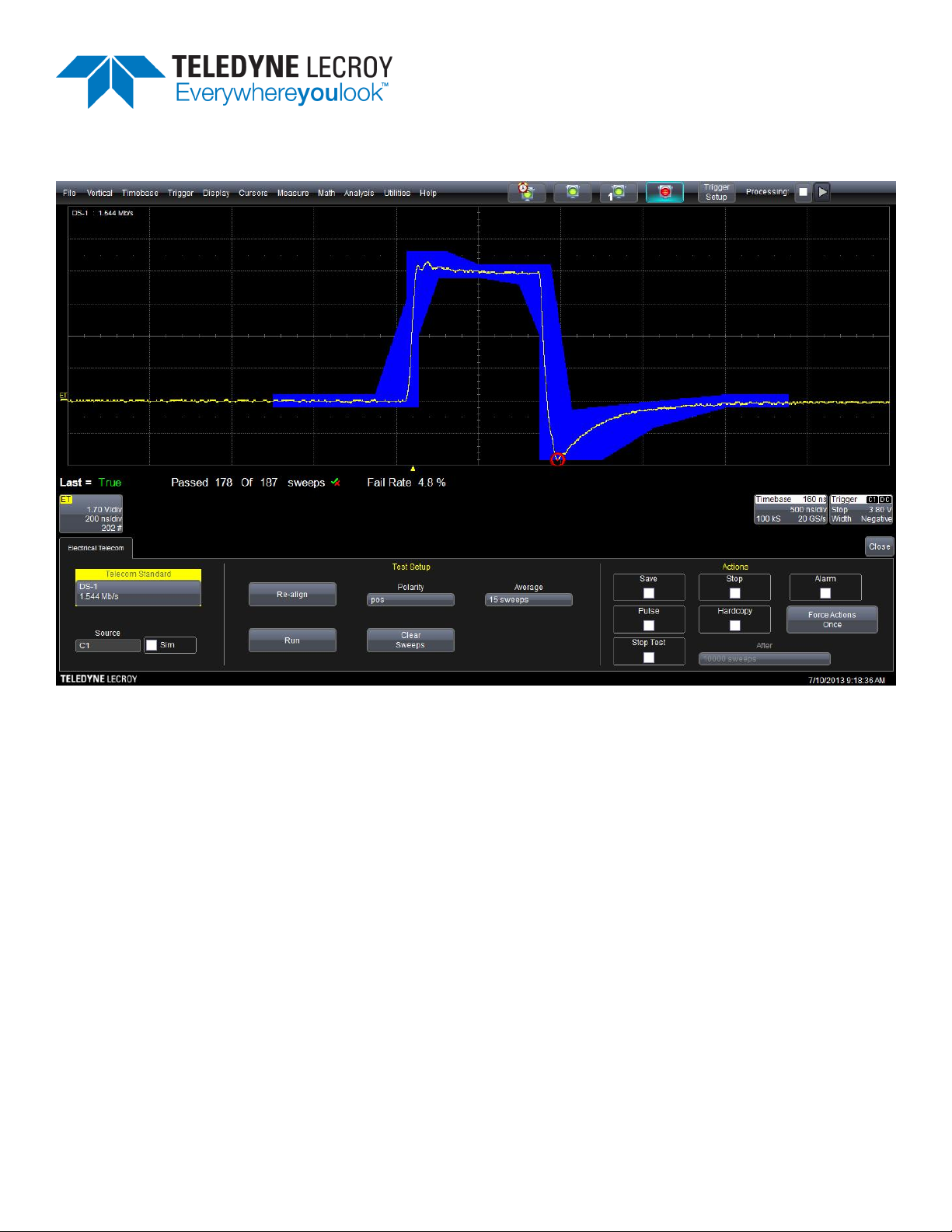
7. When setup is complete, press Run to begin the test. The Run button changes to Pause as the test is
running.
The example below shows a stopped test with a failure identified (red circle).
8. To pause the test without resetting the counter, press Pause. Press Run again to resume testing.
To stop the test and reset the counter, press Clear Sweeps.
923136 Rev A
5
Page 8

Electrical Telecom Pulse Mask Test Software
Add Measurements to Mask Test
In addition to measuring pulse compliance relative to a given mask, a full set of parametric measurements
are available. Measurements are made on the masked waveform as it appears on screen.
NOTE: Some measurements are incremental and will be reset if you Clear Sweeps during the test.
1. From the menu bar, choose Measure > Measure Setup and choose a parameter location (Px).
2. Touch Source and select ET.
3. Touch Measure and select the desired measurement parameter. If right-hand dialogs offer additional
settings for the selected parameter, enter values on these dialogs.
The measurement read out appears in a table beneath the grid.
4. To place markers exactly where on the waveform measurements are being made, choose a Marker type
and check Always On in the Help section of the dialog.
You can repeat this setup with different parameters for as many locations as your instrument offers.
6
923136 Rev A
Page 9

Operator's Manual
Create Custom Mask Test
In addition to the standard pulse masks, custom masks can be created by modifying the mask definition file,
D:\Masks\PulseMasksProp.mdb, using Microsoft Access.
A complete mask definition includes:
l Mask definition properties
l Pulse alignment criteria
l Acquisition settings such as waveform averaging and persistence
Mask Definition Properties
Enter values for the properties indicated below in the PulseMasksProp.mdb table,
TelecomStandardsProps:
ID—Index that is automatically generated. Do not enter a value in this field.
Old—For internal use only; leave blank.
Standard—Name of the standard to which the selected mask is associated. For a custom mask, enter a
unique name, which will appear in the list of Standards available on the Electric Telecom dialog.
Legacy Standard—Leave blank.
Symbol—Defined mode within standard (pos, neg, one, zero, transmit, receive).
Bit rate—Bit rate of signal; defines period.
Required Bandwidth—Minimum bandwidth needed to accurately test signal.
Minimum Sample Rate—Minimum sample rate needed to accurately test signal.
Probe—Required probe or adapter; leave blank if none.
Type—Type of signal and how it will be aligned and tested. Valid entries are: Absolute, Absolute + Offset,
Relative, and Relative Peak.
Coding—Type of coding (CMI code mark inversion, AMI alternate mark inversion, etc.); used for information
only.
Pattern Isolation—Bit pattern used to isolate the pulse under test. The syntax is: bbbb/pp/aaa where bbbb is
the symbol values before the desired pattern and aaa is the value of the bits after the desired pattern. For
example, an isolated “one” would look like: 00/1/00. Bipolar pulses are defined as 1 and -1; and CMI is
handled as two bits per unit interval. A CMI 0, for example, would look like: 1/01/0.
V div—The vertical scale required for nominal amplitude in the mask. This voltage is adjusted for relative
masks.
Nom Ampl—The nominal amplitude of the pulse to be tested.
T div—Horizontal scale to have signal in mask.
ET Delay—The time in seconds between the center of the pulse (1/2 bit) and the edge where the trigger is set.
ET Center—The center of the mask in DIV (usually 5.0).
Base Point—Currently not used; leave blank.
Offset Tol (for "Absolute + Offset" type only)—The permitted tolerance to adjust the offset for a better mask fit.
923136 Rev A
7
Page 10

Electrical Telecom Pulse Mask Test Software
Gate Start—The limit in DIV in the waveform data at which the mask test is started.
Gate Stop—The limit in DIV in the waveform data at which the mask test is stopped. This property and the
one above it allow you to perform mask testing on specific pulses within a longer, more complex waveform.
Mask Data (optional) -- Hyperlink to an Access table that contains the mask data.
Mask File Name (optional)—Used if Mask Data is not specified; file name of the custom mask (*.msk file).
This file type is created by Teledyne LeCroy’s MaskMaker software.
8
923136 Rev A
Page 11

 Loading...