

Page 1
Instruction
Manual
ENETbusD Decoder
Page 2

ENETbusD Decoder Instruction Manual
© 2013 Teledyne LeCroy, Inc. All rights reserved.
Unauthorized duplication of Teledyne LeCroy documentation materials other than for internal sales and
distribution purposes is strictly prohibited. However, clients are encouraged to distribute and duplicate
Teledyne LeCroy documentation for their own internal educational purposes.
Teledyne LeCroy is a registered trademark of Teledyne LeCroy, Inc. Windows is a registered trademark
of Microsoft Corporation. Other product or brand names are trademarks or requested trademarks of
their respective holders. Information in this publication supersedes all earlier versions. Specifications are
subject to change without notice.
922665 Rev A
March 2013
Page 3

Instruction Manual
922665 Rev A
1
TABLE OF CONTENTS
Introduction .................................................................................................................. 2
About This Manual .................................................................................................................. 2
ENETbusD Option Overview .................................................................................................... 2
Serial Decode Technical Overview .......................................................................................... 3
General Approach .................................................................................................................... 3
Setting Up the Decoder .................................................................................................. 4
Enable/Disable Decoder .......................................................................................................... 5
Applying Measurements ......................................................................................................... 5
Working with the Decode Trace ..................................................................................... 7
Serial Decode Annotations ...................................................................................................... 7
Search Waveform .................................................................................................................... 8
Working with the Results Table ...................................................................................... 9
Customize Decode Result Table ............................................................................................ 10
Navigating with the Result Table ........................................................................................... 11
Export Decode Result Table .................................................................................................. 11
Teledyne LeCroy Service Centers .................................................................................. 12
Page 4

ENETbusD Decoder
2
922665 Rev A
Introduction
About This Manual
Teledyne LeCroy offers different toolsets for decoding and debugging serial data streams. These toolsets
may be purchased as optional software packages, or are provided standard with SDA and DDA model
oscilloscopes.
This manual explains how to use the ENETbusD toolset.
Assumptions
This manual is presented with the assumption that:
You have a basic understanding of the various serial data standard physical and protocol layer
specifications, and know how these standards are used in embedded controllers.
You have a basic understanding of how to use an oscilloscope, and specifically the Teledyne
LeCroy oscilloscope on which the serial trigger and decode option is installed. Only features
directly related to serial data decode are explained in this manual; please see the oscilloscope
online Help file, Operator's Manual, or Getting Started Manual for other instructions.
You have purchased and installed one of optional serial data decoders described in this manual.
Compatibility
Teledyne LeCroy is constantly expanding coverage of serial data standards and updating software. Some
capabilities covered in this documentation may only be available with the latest version of our firmware.
You can download the firmware update from teledynelecroy.com.
While some of the screen images in this manual may not exactly match what is seen on your
oscilloscope display—or show an example taken from your protocol—be assured that the functionality is
nearly identical, as much functionality is shared.
ENETbusD Option Overview
Teledyne LeCroy ENETbusD is a software decode option for 10BASE-T and 100BASE-TX Ethernet, lowspeed serial data applications. With this software, you can easily decode 100BASE-T and 10BASE-T
Ethernet signals to examine each frame within a given packet, debugging problems such as
interoperability issues, uncertain error causes, and physical-layer issues.
10BASE-T and 100BASE-TX are Ethernet protocol standards used to send and receive data across
computer networks. As more and more devices are making use of the Ethernet protocol to
communicate in embedded systems, debugging the protocol becomes increasingly difficult. Engineers
need fast, reliable tools for debugging these embedded systems communication links. ENETbusD decode
offers color-coded overlay with easy-to-understand details on the data stream’s link layer. In addition,
powerful search capabilities allow you to search the acquired waveform in a myriad of ways.
Page 5

Instruction Manual
922665 Rev A
3
Serial Decode Technical Overview
The algorithms described here at a high level are used by all Teledyne LeCroy serial decoders sold for
oscilloscopes. They differ slightly for serial data signals that have a clock embedded in data or a clock
separate from data.
The first software algorithm examines the embedded clock for each message based on a default (or user
specified) vertical level. Once the clock signal is extracted or known, the algorithm examines the
corresponding data signal at a predetermined vertical level to determine whether a data bit is high or
low. The default vertical level is usually set to 50% and is determined from a measurement of peak
amplitude of the signals acquired by the oscilloscope. It can also be set to an (absolute) voltage level, if
desired. The algorithm intelligently applies a hysteresis to the rising and falling edge of the serial data
signal to minimize the chance of perturbations or ringing on the edge affecting the data bit decoding.
NOTE: Although the decoding algorithm is based on a clock extraction software algorithm using a
vertical level, the results returned are the same as those from a traditional protocol analyzer using
sampling point-based decode.
After determining individual data bit values, another algorithm performs a decoding of the serial data
message after separation of the underlying data bits into logical groups (Header/ID, Data Length Codes,
Data, CRC, Start Bits, Stop Bits, etc.) specific to the protocol.
Finally, another algorithm applies a color overlay with annotations to the decoded waveform to mark
the transitions in the signal. Decoded message data is displayed in tabular form below the grid. Various
compaction schemes are utilized to show the data during a long acquisition (many hundreds or
thousands of serial data messages) or a short acquisition (one serial data message acquisition). In the
case of the longest acquisition, only the most important information is highlighted. In the case of the
shortest acquisition, all information is displayed (Header/ID, Data Length Codes, Data, CRC, Start Bits,
Stop Bits, etc.) with additional highlighting of the complete message frame.
General Approach
The order of your interaction with the decoder software in many ways mirrors the order of the
algorithms. You will:
Assign a protocol/encoding scheme, an input source, and a clock source (if necessary) to one of
the four decoder panels using the Serial Data and Decode Setup dialogs.
Complete the remaining dialogs required by your protocol/encoding scheme to decode
Transitions, Bits and Words.
Work with the decoded waveform and result table to analyze the decode.
While not required, we recommend the following general approach to decoding:
1. Set up the decoder.
2. Acquire a single burst of relevant data, then run the decoder.
NOTE: If the sampling rate (SR) is insufficient to resolve the signal adequately based on the bit rate
(BR) setup or clock frequency, the protocol decoding is turned OFF to protect you from incorrect
data. The minimum SR:BR ratio required is 4:1. It is suggested that you use a slightly higher SR:BR
ratio if possible, and use significantly higher SR:BR ratios if you want to also view perturbations or
other anomalies on your serial data analog signal.
Page 6

ENETbusD Decoder
4
922665 Rev A
3. Use the various analysis tools to verify that transitions are being correctly decoded. Tune the
decoder settings as needed.
4. Run the decoder on acquisitions of the desired length.
You can disable/enable the decoder as desired without having to repeat the set up and tuning
provided the basic signal characteristics do not change.
Setting Up the Decoder
You can preset up-to-four, independent decoders using the same or different protocols and data
sources. These decoders can be enabled simultaneously or separately, and for each you can select what
data appears on the display.
1. Touch the Front Panel Serial Decode button (if available on your oscilloscope), or choose Analysis >
Serial Decode from the oscilloscope menu bar to access the Serial Decode dialog.
2. On the same row as the Decode #:
Select the desired Protocol to use. The selections will depend on the software options
installed on your instrument.
Select the (Source) Data to be decoded. This can be any signal input channel, memory, or
math function. Depending on your Protocol selection, you may be required to select more
than one source. The requisite number of fields will automatically appear.
If required, select the Clock and Clock Source (CS). These controls are available for certain
protocols; they will simply not appear if not relevant.
3. Touch the Setup button to open the Decode Setup dialog. If you use this method rather than the
tab, the correct decoder will be selected by default.
4. Go on to complete the settings required for the ENET protocol on the right-hand dialogs next to the
Decode Setup dialog.
Probe Selection - choose whether your signal input device is One Differential Probe or Two-Single
Ended Probes. Depending on your selection, the left-hand side Decode Setup dialog will display
either of the following entry fields:
Dp-Dn - if you are using a single differential probe, a single entry field appears. Select the
source input channel to which the probe is connected.
Dp and Dn - if you are using two single-ended probes, two entry fields appear. Select the
input channels for both the positive (Dp) and the negative (Dn) inputs.
Detect AutoNegotiation (100M ENET only) - Check this box to mark on the decode trace
occurrences of Auto Negotiation in the decoded signal.
TIP: After completing one decoder, you can quickly start setup for the other decoders by using the
Decode # buttons at the left of the Decode Setup dialog. You don't have to step back to the Serial
Decode dialog to start the setup. Controls with the same label on either dialog share the same
function.
Page 7

Instruction Manual
922665 Rev A
5
Enable/Disable Decoder
Once preset, the four decoders can be enabled simultaneously or separately as often as you wish,
although this number may be limited depending on the type of source channels selected. Preset
decoders can be easily disabled without disrupting the configuration.
To enable:
Press the Front Panel Serial Decode button, or choose Analysis > Serial Decode, to open the Serial
Decode dialog, then check Decode On next to the respective decoder.
If View Decode is checked (default) on the Decode Setup dialog, a result table and decoded waveform
appears for each enabled decoder. The number of rows of data displayed on each table will depend on
the Table#Rows setting. The default is one, which can be increased, but doing so will decrease the
amount of the screen available to display traces.
To disable:
Deselect the Decode On box individually, or touch Turn All Off.
Applying Measurements
After the decoder has been enabled on a valid acquisition, measurements can be applied to the decoded
waveform. These measurements appear in a tabular readout below the grid (the same as for any other
measurements) and are in addition to the result table that shows the decoded data. You can set up as
many measurements as your oscilloscope has parameter locations.
From the Result Table
The decoder offers a sub-set of measurements designed for serial data analysis. To quickly apply these
measurements:
1. Touch any data cell of the decode result table.
NOTE: If you're running more than one decoder simultaneously, be sure to select a cell from the
correct table, as the measurement source will be whichever waveform belongs to the table you
touch.
2. From the pop-up menu, select Measure to display the Select Operation... dialog.
Page 8

ENETbusD Decoder
6
922665 Rev A
3. Touch any measurement operation to select it. Options are:
View Serial Encoded Data as Analog Waveform - Automatically sets up a Message to Value
parameter and then tracks the assigned measurement. In doing so, a Digital-to-Analog
Conversion (DAC) of the embedded digital data is performed and the digital data is displayed
as an analog waveform.
Message to Value - Extract and convert a specific portion of the data/payload in the message
and display it as an analog value.
MsgToAnalog (Message to Analog) - Computes the time difference from a protocol message
to the crossing of a threshold on an analog signal.
AnalogToMsg (Analog to Message) - Computes the time difference from the crossing of a
threshold on an analog signal to a protocol message.
MsgToMsg (Message to Message) - Computes the time difference from one protocol
message to another protocol message.
DeltaMsg (Delta Message) - Computes the time difference between two messages on a single
decoded line.
Time@Msg (Time at Message) - Time from trigger to each protocol message (meeting
specified conditions).
BusLoad - Computes the load of user-defined messages on the bus (as a percent).
MsgBitrate - Computes the bitrate of user-specified messages on decoded traces.
NumMessages (Number of Messages) - Computes the number of messages which match a
user-specified definition in decoded traces.
4. On the next dialog, choose a parameter location (P1-Px) in which to run the measurement.
NOTE: If you choose a location that already stores a measurement, this selection will overwrite that
setup.
From the Decode Setup Dialog
You can also access the Select Operation... dialog of serial data measurements by touching the Measure
button on the Decode Setup dialog. Follow Steps 3 and 4 above to set up the measurements.
Measurements are set on the source of whichever Decoder (1-4) is currently selected on the Decode
Setup dialog.
From the Measure Menu
The full menu of available measurements can be accessed through the menu bar. Choose Measure >
Measure Setup and follow the usual procedures for setting up a measurement. In this case, you will
have to manually choose the source to measure.
Page 9

Instruction Manual
922665 Rev A
7
Working with the Decode Trace
Serial Decode Annotations
When a decoder is enabled, an annotated waveform showing the results of the decode appears on the
oscilloscope display.
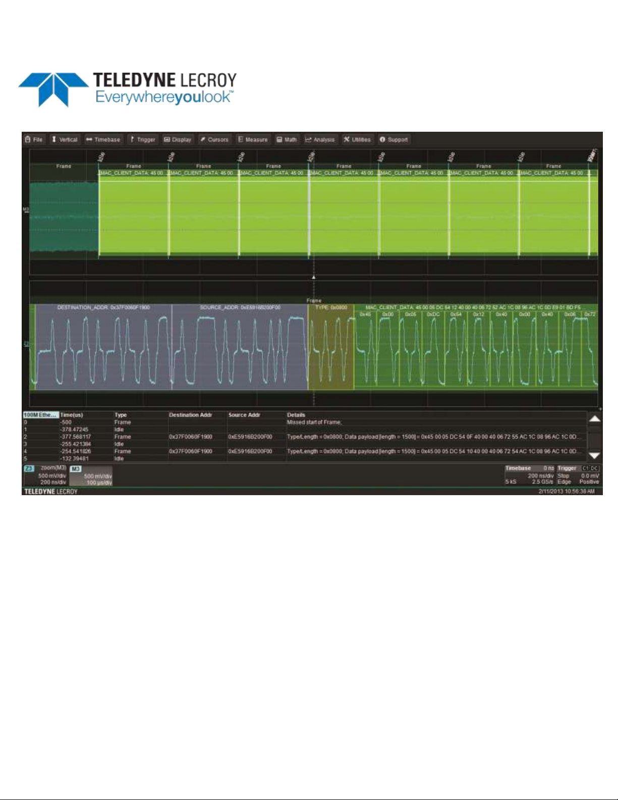
A colored overlay marks significant transitions in the source signal. The overlay contains annotations
corresponding to the data itself, any pre/post-message padding, inter-burst periods, etc. Each set of
annotations is customized to the protocol or encoding scheme. The amount of information shown on an
annotation is affected by the width of the rectangles in the overlay, which is determined by the
magnification (scale) of the trace and the length of the acquisition.
These overlays appear on the decoded ENET waveform or its zoom trace to highlight key portions of the
decoded signal.
Frame - Dark green overlay, indicating single Ethernet frame (packet) decoded.
Idle - Bright aqua overlay showing idle time between frames.
Destination and Source Addresses - Gray overlay to left of Type, showing 48-bit MAC addresses of
destination and source nodes.
Type - Olive overlay to left of client data indicating the EtherType/Length of the encapsulated payload
message.
MAC_Client_Data - Green or bright green overlay, showing payload data . At sufficiently zoomed
resolutions, this overlay will show all the decoded bits.
Pre-Amble (not shown) - Green overlay showing Pre-amble bits.
FCS (not shown) - Tan overlay showing Frame Check Sequence bits.
Decoded waveform. At this resolution, very little information appears on the overlay.
Zoomed waveform, showing annotation details.
Page 10

ENETbusD Decoder
8
922665 Rev A
Search Waveform
Choosing Search on the Decode Setup dialog opens a Zoom of the original decoded waveform and
displays the corresponding Zoom dialog with the standard rescaling controls.
Use the <protocol> Search right-hand dialog to enter the search criteria. Then, use the navigation
buttons on the Search dialog to find the previous or next event in the trace that matches the search
criteria.
NOTE: If the match is found in a message currently displayed on the result table, that row will be
highlighted. However, if it is not displayed, the Search navigation buttons will not automatically bring up
that table row, although they will navigate the trace. Use the scrollbar at the right of the result table to
find the row containing the search result.
The default Zoom always presents the found event at the full width of the grid. Use the Zoom dialog
controls to rescale the Zoom to the desired level of magnification.
Choose from the following options on the ENET Search dialog.
Any - Any Ethernet protocol element (frame or idle time). This option finds the next row in the result
table, so you can use the Search navigation buttons to scroll the table (up to the number of rows
displayed).
Frame - Next frame. Also choose either:
Don't Care(default) - any frame
Type (Hex) - next frame of this EtherType/Length. Clear Don't Care to activate this field, then
enter the hex code for the desired type. Refer to IEEE standard 802.3 for a list of valid codes.
Src_Address - MAC address of node from which packet sent. Also either:
Enter the Address Value, or
Touch Copy From Frame to copy the value from the highlighted table row and search for that.
Dest_Address - MAC address of node to which packet sent. Also either:
Enter the Address Value, or
Touch Copy From Frame to copy the value from the highlighted table row and search for that.
TP_Idle (10M ENET) or Idle (100M ENET) - Next idle time between frames.
Link Integrity Test (10M ENET only) - Next link test signal.
FLP Burst - Next fast link pulse burst.
Electrical Idle - Next drop in electrical signal.
Protocol Error - Next error. Also choose the Protocol Error Type from among:
Any
Missed Terminate
Missed Start of Frame
4B5B Error
(continued next page)
Page 11

Instruction Manual
922665 Rev A
9
Frame Length Error
Preamble Value Error
SDF Value Error
CRC Error
Data Size Error
Unknown - Next occurrence of an unknown frame type.
Working with the Results Table
By default, a table summarizing the decoder results appears below the grids whenever a decoder is
enabled. The decode result table provides a view of message data as decoded by the oscilloscope during
the most recent acquisition, even when messages are too compact to allow annotation on the waveform
trace.
The table is displayed only when the View Decode checkbox is marked on the Decode Setup Dialog and
a source signal has been decoded using that protocol.
You can customize the result table, changing both the number of rows and the columns displayed. The
default is one row. A scrollbar at the right of the table lets you display the previous or next row of table
data.
On a single-row table, touch the Down arrow to open the scrollbar.
You can also export result table data to a .CSV file, and the table itself provides a useful tool for
navigating and measuring.
Page 12
ENETbusD Decoder
10
922665 Rev A
Customize Decode Result Table
Follow these steps to change which decode values appear in the result table:
1. Press the Front Panel Serial Decode button, or choose Analysis > Serial Decode, then open the
Decode Setup tab.
2. Touch the Configure Table button.
3. On the View Columns pop-up dialog, check boxes for the columns you want to appear in the table.
Clear boxes for any columns you wish to remove. Only those columns selected will appear on the
oscilloscope display.
To return to the preset display, touch Default.
4. Optionally, set a BitRate Tolerance percentage. This value will allow for signal jitter correction while
decoding.
5. Touch the Close button when finished.
6. Optionally, on the Decode Setup dialog enter the Table # Rows to display. Each row will contain data
from one decoded message.
NOTE: Keep in mind that displaying several, multiple-row tables will reduce the amount of screen
space available for the waveform grids.
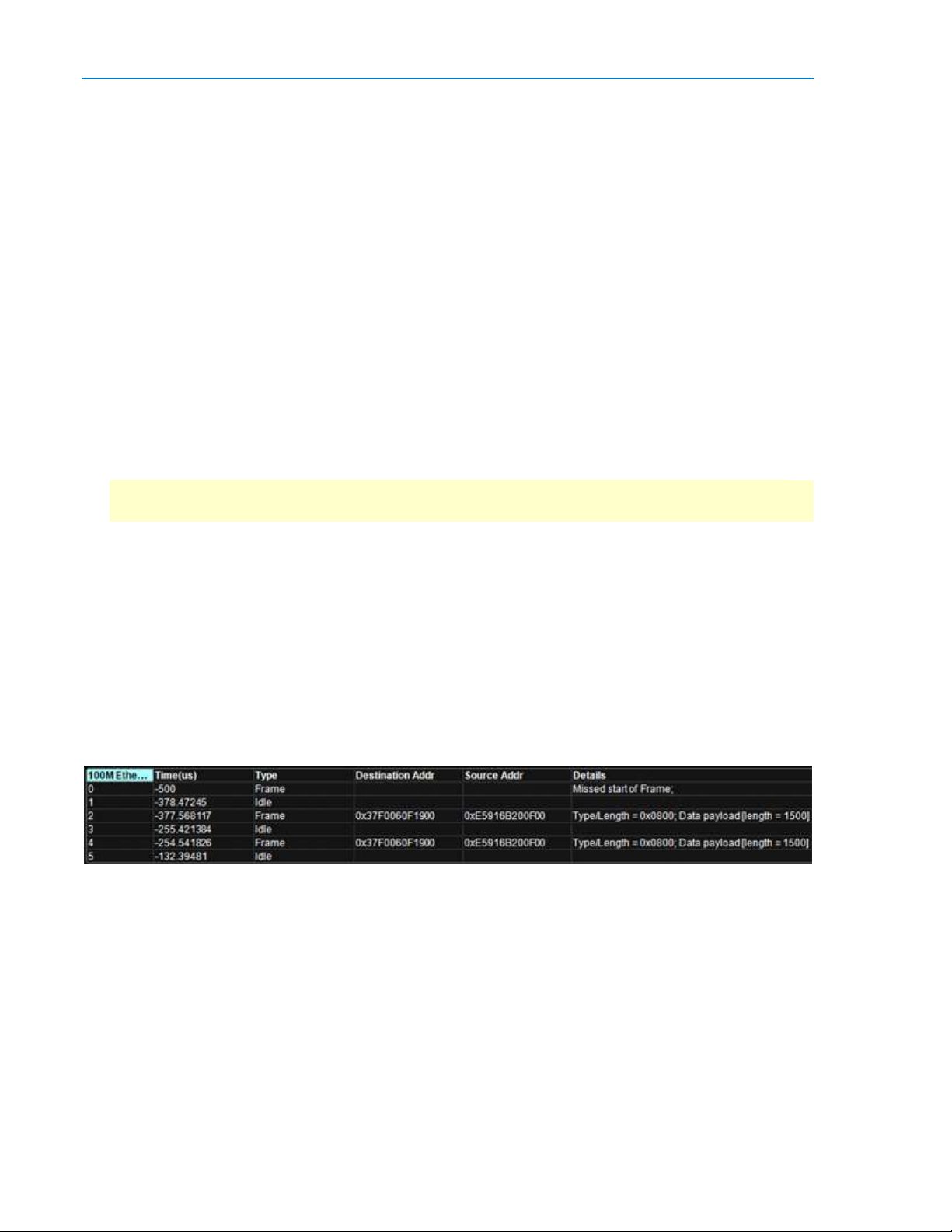
You may display or hide these columns on the ENET result table.
Time(us) - Time (in microseconds) of the beginning of the frame, with respect to the trigger time
of the acquisition.
Type - Frame or Idle time.
Dest Addr - Packet destination MAC address.
Source Addr - Packet origination MAC address.
Details - Decoded data (type and payload), or type of protocol error if decode failed.
Section of typical ENET result table.
Page 13

Instruction Manual
922665 Rev A
11
Navigating with the Result Table
Besides displaying the decoded serial data, the result table enables you to quickly Zoom regions of the
decoded waveform and control decoder dialogs.
The first column heading (top, left-most cell of the table header) bears the name of the corresponding
protocol, and the cell's fill color matches the color of the input source. Touching this cell opens the
Decode Setup dialog if it has been closed.
Touching the row number in the first column opens a Zoom of the corresponding region in the decode
trace.
Touching any other data cell in the table opens a pop-up menu with several choices of action:
Off turns off the decoder.
Zoom creates a zoom of the region where the data appears (same as touching the row number).
Setup opens the Decoder Setup dialog (same as touching the first column heading).
Export exports the decode results table to a .CSV file.
Measure displays a dialog of various measurements that can be made on the source signal.
Export Decode Result Table
You can export the decode result table data to a .CSV file.
Export files are by default created in the Xstream\Applications\<protocol> folder, although you can
choose any other folder on the oscilloscope, or any external drive connected to a host USB port. The
data will overwrite the last export file saved in the protocol directory, unless you enter a new filename.
To export the result table:
1. Press the Front Panel Serial Decode button, or choose Analysis > Serial Decode, then open the
Decode Setup tab.
2. Optionally, touch Browse and enter a new File Name and output folder.
3. Touch the Export Table button.
Page 14

ENETbusD Decoder
12
922665 Rev A
Teledyne LeCroy Service Centers
United States and Canada - World Wide Corporate Office
Teledyne LeCroy Corporation
700 Chestnut Ridge Road
Chestnut Ridge, NY, 10977-6499, USA
Ph: 800-553-2769 / 845-425-2000
FAX: 845-578-5985
teledynelecroy.com
Support:
contact.corp@teledynelecroy.com
Sales:
customersupport@teledynelecroy.com
United States - Protocol Solutions Group
Teledyne LeCroy Corporation
3385 Scott Boulevard
Santa Clara, CA, 95054, USA
FAX: 408-727-0800
teledynelecroy.com
Sales and Service:
Ph: 800-909-7211 / 408-727-6600
contact.corp@teledynelecroy.com
Support:
Ph: 800-909-7112 / 408-653-1260
psgsupport@teledynelecroy.com
European Headquarters
Teledyne LeCroy SA
4, Rue Moïse Marcinhes
Case postale 341
1217 Meyrin 1
Geneva, Switzerland
Ph: + 41 22 719 2228 / + 41 22 719 2323 / + 41 22 719 2277
FAX: +41 22 719 2233
contact.sa@teledynelecroy.com
applications.indirect@teledynelecroy.com
teledynelecroy.com/europe
Protocol Analyzers:
Ph: +44 12 765 03971
Singapore, Oscilloscopes
Teledyne LeCroy Singapore Pte Ltd.
Blk 750C Chai Chee Road #02-08
Technopark @ Chai Chee
Singapore 469003
Ph: ++ 65 64424880
FAX: ++ 65 64427811
Page 15

922665 Rev A
13
Singapore, Protocol Analyzers
Genetron Singapore Pte Ltd.
37 Kallang Pudding Road, #08-08
Tong Lee Building Block B
Singapore 349315
Ph: ++ 65 9760-4682
China
Teledyne LeCroy Corporation Beijing
Rm. 2001
Unit A, Horizon Plaza
No. 6, Zhichun Road, Haidian District
Beijing 100088, China
Ph: ++86 10 8280 0318 / ++86 10 8280 0319 / ++86 10 8280 0320
FAX:++86 10 8280 0316
Service:
Rm. 2002
Ph: ++86 10 8280 0245
Taiwan
LeColn Technology Co Ltd.
Far East Century Park, C3, 9F
No. 2, Chien-8th Road,
Chung-Ho Dist., New Taipei City, Taiwan
Ph: ++ 886 2 8226 1366
FAX: ++ 886 2 8226 1368
Instruction Manual
Korea
Teledyne LeCroy Korea
10th fl.Ildong Bldg.
968-5 Daechi-dong, Gangnam-gu
Seoul 135-280, Korea
Ph: ++ 82 2 3452 0400
FAX: ++ 82 2 3452 0490
Japan
Teledyne LeCroy Japan
Hobunsya Funchu Bldg, 3F
3-11-5, Midori-cho, Fuchu-Shi
Tokyo 183-0006, Japan
Ph: ++ 81 4 2402 9400
FAX: ++ 81 4 2402 9586
teledynelecroy.com/japan
Page 16

 Loading...